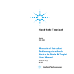
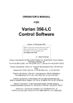
1
Turbo-V 300 75 Vdc Box Controller Model SQ 189 User Manual 87-900-939-01 (F) 04/2011 Warranty Notices © Agilent Technologies, Inc. 2011 No part of this manual may be reproduced in any form or by any means (including electronic storage and retrieval or translation into a foreign language) without prior agreement and written consent from Agilent Technologies, Inc. as governed by United States and international copyright laws. Manual Part Number Publication Number: 87-900-939-01 (F) Edition Edition 04/2011 Printed in ITALY Agilent Technologies Italia S.p.A. Vacuum Products Division Via F.lli Varian, 54 10040 Leinì (TO) ITALY The material contained in this document is provided “as is,” and is subject to being changed, without notice, in future editions. Further, to the maximum extent permitted by applicable law, Agilent disclaims all warranties, either express or implied, with regard to this manual and any information contained herein, including but not limited to the implied warranties of merchantability and fitness for a particular purpose. Agilent shall not be liable for errors or for incidental or consequential damages in connection with the furnishing, use, or performance of this document or of any information contained herein. Should Agilent and the user have a separate written agreement with warranty terms covering the material in this document that conflict with these terms, the warranty terms in the separate agreement shall control. Technology Licenses The hardware and/or software described in this document are furnished under a license and may be used or copied only in accordance with the terms of such license. Restricted Rights Legend If software is for use in the performance of a U.S. Government prime contract or subcontract, Software is delivered and licensed as “Commercial computer software” as defined in DFAR 252.227-7014 (June 1995), or as a “commercial item” as defined in FAR 2.101(a) or as “Restricted computer software” as defined in FAR 52.227-19 (June 1987) or any equivalent agency regulation or contract clause. Use, duplication or disclosure of Software is subject to Agilent Technologies’ standard commercial license terms, and nonDOD Departments and Agencies of the U.S. Government will receive no greater than Restricted Rights as defined in FAR 52.227-19(c)(1-2) (June 1987). U.S. Government users will receive no greater than Limited Rights as defined in FAR 52.227-14 (June 1987) or DFAR 252.227-7015 (b)(2) (November 1995), as applicable in any technical data. Trademarks Windows and MS Windows are U.S. registered trademarks of Microsoft Corporation. Safety Notices CAUTION A CAUTION notice denotes a hazard. It calls attention to an operating procedure, practice, or the like that, if not correctly performed or adhered to, could result in damage to the product or loss of important data. Do not proceed beyond a CAUTION notice until the indicated conditions are fully understood and met. WARNING A WARNING notice denotes a hazard. It calls attention to an operating procedure, practice, or the like that, if not correctly performed or adhered to, could result in personal injury or death. Do not proceed beyond a WARNING notice until the indicated conditions are fully understood and met. Turbo-V 300 75 Vdc Box Controller User Manual / 87-900-939-01 (F) Turbo-V 300 75 Vdc Box Controller Turbo-V 300 75 Vdc Box Controller Turbo-V 300 75 Vdc Box Controller User Manual / 87-900-939-01 (F) 3/34 Turbo-V 300 75 Vdc Box Controller 4/34 Turbo-V 300 75 Vdc Box Controller User Manual / 87-900-939-01 (F) Contents Contents 1 Instructions for Use 7 Introduction 8 Disposal 2 9 Technical Information 11 Description 12 Turbo-V 300 75 Vdc Box Controller Description 12 Controller Specifications 13 Controller Outline 14 Installation 15 Operation 24 Maintenance 25 PCB Jumpers 27 Turbo-V 300 75 Vdc Box Controller User Manual / 87-900-939-01 (F) 5/34 Contents 6/34 Turbo-V 300 75 Vdc Box Controller User Manual / 87-900-939-01 (F) Turbo-V 300 75 Vdc Box Controller User Manual 1 Instructions for Use Introduction Disposal 8 9 7/34 Instructions for Use Introduction 1 Introduction Operators and service personnel must be aware of all hazards associated with this equipment. They must know how to recognize hazardous and potentially hazardous conditions, and know how to avoid them. The consequences of unskilled, improper, or careless operation of the equipment can be serious. This product must only be operated and maintained by trained personnel. Every operator or service person must read and thoroughly understand operation/maintenance manuals and any additional information provided by Agilent. All warnings and cautions should be read carefully and strictly observed. Address any safety, operation, and/or maintenance questions to your nearest Agilent office. The following format is used in this manual to call attention to hazards: CAUTION! WARNING! NOTE 8/34 Cautions are used when failure to observe instructions could result in damage to equipment, whether Agilent supplied or other associated equipment. Warning are used when failure to observe instructions or precautions could result in injury or death. Information to aid the operator in obtaining the best performance from the equipment. Turbo-V 300 75 Vdc Box Controller User Manual / 87-900-939-01 (F) 1 Instructions for Use Disposal Disposal Meaning of the "WEEE" logo found in labels The following symbol is applied in accordance with the EC WEEE (Waste Electrical and Electronic Equipment) Directive. This symbol (valid only in countries of the European Community) indicates that the product it applies to must NOT be disposed of together with ordinary domestic or industrial waste but must be sent to a differentiated waste collection system. The end user is therefore invited to contact the supplier of the device, whether the Parent Company or a retailer, to initiate the collection and disposal process after checking the contractual terms and conditions of sale. Turbo-V 300 75 Vdc Box Controller User Manual / 87-900-939-01 (F) 9/34 1 Instructions for Use Disposal 10/34 Turbo-V 300 75 Vdc Box Controller User Manual / 87-900-939-01 (F) Turbo-V 300 75 Vdc Box Controller User Manual 2 Technical Information Description 12 Turbo-V 70 75 Vdc Box Controller Description 12 Controller Outline 13 Controller Specifications 13 Controller Outline 14 Installation 15 Pump Connector 15 Serial Communication Port 16 RS 232 Communication Descriptions 17 Transmission Channel Characteristics 17 Message Structure 18 Examples: 19 Operation 24 Switching on/off the Pump 24 Low Speed Activation/Deactivation 24 Maintenance 25 XError Messages 25 PCB Jumpers 27 X 11/34 2 Technical Information Description Description The Turbo-V 300 box controller is a microprocessor-controlled, solidstate, frequency converter with self-diagnosis and protection features. The controller drives the Turbo-V 300 pump series by controllling the voltage and current respect to the speed reached by pump. It incorporates all the facilities required for the operation of the TurboV 300 pump series: pump start/stop, digital current and speed control, analog signals for external indicators. The power is externally supplied. All the input/output connections are performed on: 9 pin “D” type male connector attached to a cable 400 mm long for I/O and Electrical DC supply. Pump connection with 400 mm long cable. 9 pin “D” type connector for RS232 connection. Turbo-V 300 75 Vdc Box Controller Description The controller is a solid-state frequency converter which is driven by a single chip microcomputer and is composed of a PCB which includes all the circuitry necessary for its operation. The microcomputer generates the variable output voltage according to the software and the gas load condition of the pump. Moreover, it manages signals from sensors, input/output connection information, and gives output for a fully automatic operation. The controller can be operated via remote signals through an RS-232 connection. The controller can be operated in local mode through suitable switches connected between the input pins of the TV300 connector. 12/34 Turbo-V 300 75 Vdc Box Controller User Manual / 87-900-939-01 (F) Technical Information Controller Specifications 2 Controller Specifications Table 1 CAUTION! Controller Specifications Input: - Voltage - Current 75 Vdc with 2 Vpp max ripple 3.0 A max. Fuse T3A Output: - Voltage - Frequency - Power 80 Vac nominal ±10%, 3-phase 933 Hz, ±2% 165 W maximum Compliance to Norms: - Radio interferences - ESD - BURST - Radiated RF immunity - Safety EN 55011 Class Group 1 EN 61000/4/2 EN 61000/4/4 EN 61000/4/3 EN 61010/1 Installation category II Operating temperature 0 °C to + 40 °C Storage temperature -20 °C to + 70 °C Cooling Internal fan Weight 0.5 Kg (1.1 Ibs) There can be 75 Vdc voltage referred to ground on the pump cable or on the serial connector. Turbo-V 300 75 Vdc Box Controller User Manual / 87-900-939-01 (F) 13/34 2 Technical Information Controller Outline Controller Outline The outline dimension for the controller are shown in the following figure: Figure 1 14/34 Controller outline Turbo-V 300 75 Vdc Box Controller User Manual / 87-900-939-01 (F) 2 Technical Information Installation Installation Inspect the controller for any shipping damage. Should the controller be connected to a host computer via the-RS-232 interface, a suitable cable must be prepared. In the following paragraphs are detailed the input/output signals. NOTE The box installed into the customer system must be positioned so that cold air (forced or natural convection) can flow around. Pump Connector The signals of J3 connector are the following: Pin C 80 Vac 3-phase output to pump motor stator (phase T). Pin D 80 Vac 3-phase output to. pump motor stator (phase S). Pin B 80 Vac 3-phase output to pump motor stator (phase R). Pins A/F Pump temperature sensor. Pin E Ground Table 2 I/O Specifications START/STOP: - START command - STOP command Analog output: - Output impedence - Minimum load: Normal operation signal: - Open Collector Low <0.8 Vdc High 4 to 15 Vdc 0 to 10 Vdc (proportional to speed) * (0 to 10 V ≡ 0 to 100 % speed) 0.1 Ω 2 KΩ (5 mA) Speed <80 %: OFF (pull-up to 15 Vdc) Speed >80 %: ON (<0.8 Vdc) Current rating 60 mA max Low speed command: Low (<0.8 Vdc) Turbo-V 300 75 Vdc Box Controller User Manual / 87-900-939-01 (F) 15/34 2 Technical Information Installation Table 3 9-pin “D” Type Connector Pin Assignement Pin number Description 1 Start/Stop input: close to pin 5/6 to start the pump 2 Pump in Normal output: closed to pin 5/6 when pump speed is higher than 80% of full speed 3 Earth (Ground) 4 Analog output proportional to pump speed (positive) 5-6 Electrical supply (0 V) 9 Low speed input: close to pin 5/6 to select Low Speed mode 7-8 Electrical supply (75 V) (positive) * Minimum speed reading in STOP condition = 100 Hz (6 KRPM) Serial Communication Port Communication serial port connections and mini- mum connection configuration are shown in the following figures. The communication port mating connector is supplied with the RS 232 PCB (AMP/Cannon or equivalent 9-pin "D" type male connector). The external cable (not supplied) between the host computer and the controller does not require crossed wires so that signals are connected correctly . For example, the Transmit data signal from controller (pin 2) must be connected to the host computer's Receive data line (pin 2) and vice versa. Consult the host computer's instruction manual for its serial port connections NOTE 16/34 Agilent cannot guarantee compliance with FCC regulations for radiated emissions unless all external wiring is shielded, with the shield being terminated to the metal shroud on the O-subconnector. The cable should be secured to the connector with screws. Turbo-V 300 75 Vdc Box Controller User Manual / 87-900-939-01 (F) Technical Information Installation CAUTION! 2 In order to avoid possible conflicts on the Serial Line, it is advisable to use a 3 wire shielded cable for the TxD, RxD and GND connections and to leave all the other pins unconnected. RS 232 Communication Descriptions Figure 2 Communication RS 232 serial port connections Transmission Channel Characteristics levels: baud rate: character length: parity: stop bit: protocoll: RS 232/RS 422 9600/4800 programmable by a jumper on the board 8 bits none 1 bit master (PC) / slave (converter) In this case the value to be assigned to the ADDRESS field must be 80 hex (for RS 232). Turbo-V 300 75 Vdc Box Controller User Manual / 87-900-939-01 (F) 17/34 2 Technical Information Installation Message Structure (request and answer have the same format) The master system (PC) starts every session sending the following message to the slave units connected: <STX> / <ADDR> + <WINDOW> + <COMMAND> + <DATA> + <ETX> + <CRC> where: <STX>= 0x02 <ADDR> = 0x80 (for RS 232 and RS 422 only) <ADDR> = 0x80 + device number (0...31) 0xFF: brodcasting command (recognized by all the devices, it doesn’t implicate any answer) (for RS 485 only) <WINDOWS>= '000'...' 999' window number the meaning of the window depends to the device type <COMMAND>= 0x30 :window value reading 0x31 :window writing <DATA> = alphanumeric ASCII string containing, in the case of writing operation, the parameter to input into the window addressed by the field <WINDOW>This field may have variable length according to the data type contained in the window where you are working in. In the case of reading request of a window, the data field doesn’t exist. <ETX>= 0x03 <CRC>= XOR among all the characters following <STX>=(with exception of <STX>), including the end character <ETX> hexadecimally encoded by two ASCII characters When a slave device is addressed by the master: 18/34 Turbo-V 300 75 Vdc Box Controller User Manual / 87-900-939-01 (F) Technical Information Installation 2 1) In case of reading request of the value contained in a window, the slave answers a string equal to the one sent by the master but in addition there is the field <DATA> containing the value of the window. The format of the field <DATA> depends to the window type. The different types are: Logic (L) Length Characters Permitted 1 ‘0’= OFF ‘1’ = ON ‘0’...’9’ Numeric (N) 6 Alphanumeric (A) max 10 (Justifield to the right with ‘0’) ‘ ‘...’_’ Examples: Command : Source : Destination : 02 80 STX ADDR START PC Inverter 30 30 30 WINDOW Source : Destination : 80 06 03 STX ADDR ACK ETX Command : Source : Destination : 80 STX ADDR 31 03 WR ON ETX 31 30 03 WR OFF ETX 42 33 CRC Inverter PC 02 02 31 38 33 CRC STOP PC Inverter 30 30 30 WINDOW 42 32 CRC Turbo-V 300 75 Vdc Box Controller User Manual / 87-900-939-01 (F) 19/34 2 Technical Information Installation Source : Destination : Inverter PC 02 80 06 03 STX ADDR ACK ETX Command : Source : Destination : 02 80 STX ADDR 31 30 30 WINDOW 80 06 03 STX ADDR ACK ETX Command : Source : Destination : 80 STX ADDR 30 32 WR ON ETX CRC 42 35 31 30 03 WR OFF ETX 30 03 38 RD ETX 33 CRC Inverter PC 80 06 03 STX ADDR ACK ETX Command : Source : Destination : ADDR 42 CRC 30 02 STX 03 38 WINDOW Source : Destination : 80 31 SOFT-START (OFF) PC Inverter 31 02 31 Inverter PC 02 02 35 CRC SOFT-START (ON) PC Inverter Source : Destination : 20/34 38 38 35 CRC CURRENT PC Inverter 32 30 30 WINDOW 31 CRC Turbo-V 300 75 Vdc Box Controller User Manual / 87-900-939-01 (F) 2 Technical Information Installation Source : Destination : Inverter PC 02 80 32 STX ADDR WINDOW Command : Source : Destination : 02 80 STX ADDR 30 32 30 32 STX ADD WINDOW 30 Command : Source : Destination : ADDR 30 2E 30 30 000.00 03 39 ETX 44 CRC 33 30 03 38 RD ETX 32 CRC 33 30 30 30 RD 30 30 34 32 000042 03 ETX 38 34 CRC ERR-CODE PC Inverter 32 30 36 WINDOW Source : Destination : 30 Inverter PC 80 STX 30 RD WINDOW 02 80 30 FREQUENCY PC Inverter Source : Destination : 02 30 30 03 38 RD ETX 37 CRC Inverter PC 02 80 32 30 STX ADD WINDOW 36 30 RD 30 30 30 30 000000 Turbo-V 300 75 Vdc Box Controller User Manual / 87-900-939-01 (F) 30 30 03 ETX 38 37 CRC 21/34 Technical Information Installation 2 Table 4 Serial Communication Windows WIN TYPE R W Description 000 L X X START/STOP (1= START ; 0= STOP) 008 L X X REMOTE/SERIAL Configuration (1= Remote ; 0= Serial) 100 L X X SOFT START YES/NO (1= YES ; 0= NO) Default= 0 107 L X X SOFT START YES/NO (1= YES ; 0= NO) Default= 1 108 N X X BAUD RATE (3-4) [4800-9600] Default= 4 109 L X PUMP LIFE RESET [Write “1” to Reset] 120 N X X SET ROTATIONAL FREQUENCY [Hz] 121 N X X MAX SETTABLE ROTATIONAL FREQUENCY [Hz] F<=F_MAX_ABS 130 N X RAMP CURRENT [mA] 200 N X CURRENT [mA] 201 N X VOLTAGE[V] 202 N X POWER [W] 203 N X DRIVING FREQUENCY [Hz] 204 N X PUMP TEMPERATURE [°C] 205 N X STATUS [0=stop; 1=interlock; 2=ramp; 3=regulation; 4=brake; 5=normal; 6=failure] 206 N X ERROR CODE: 150 Hz < = F_imp < = FMAX 7 0 Too high load No connection Short circuit Pump overtemp SoftStart Not Ended Controller overte RunUpTime Not Reached Power fail 211 N X PUMP SENSOR TEMPERATURE READING [208= 25°C - 128= 60°C] 216 N X AMBIENT SENSOR TEMPERATURE READING 300 N X CYCLE TIME [min] 301 N X CYCLE NUMBER 302 N X PUMP LIFE [h] 22/34 Turbo-V 300 75 Vdc Box Controller User Manual / 87-900-939-01 (F) Technical Information Installation WIN TYPE R W 319 A X Controller Model 320 A X Base Pump Model Number (8 characters) 321 A X Modified Standard Model Number (4 characters) 323 A X Controller Serial Number (5 characters) 325 A X Electrical Modification Level (10 characters) 400 A X CRC PROGRAM LISTING [QE7xxxx] 401 A X CRC BOOTLOADER [BL1xxxx] 402 A X CRC PARAMETER LISTING [PA7xxxx] Description 404 A X CRC FILE PARAMETER STRUCTURE 406 A X PROGRAM LISTING CODE & REVISION 407 A X PARAMETER LISTING CODE & REVISION 500 L WIN = Window R = Read W = Write X 2 MONITOR MODE L = Logical N = Numeric A = Alphanumeric Turbo-V 300 75 Vdc Box Controller User Manual / 87-900-939-01 (F) 23/34 2 Technical Information Operation Operation Make all vacuum manifold and electrical connections and refer to Turbo-V pump instruction manual prior to operating the Turbo-V controller. WARNING! To avoid injury to personnel and damage to the equipment, if the pump is laying on a table make sure it is steady. Never operate the Turbo-V pump if the pump inlet is not connected to the system or blanked off. The controller operates completely automatically after the remote start command is given. Switching on/off the Pump To switch on the pump it is necessary to short circuit pin 1 and pins 5-6 (ground) of the 9 pin “D” type connector. To switch off the pump it is necessary to remove the short circuit between pins 1 and 5-6. Analog output: 0 to 10 Vdc proportional to speed (0 to 10 V ≡ 0 to 100% speed). This output is active also during the pump “slow down” phase after a Stop command. Low Speed Activation/Deactivation To activate the Low Speed status it is necessary to connect pin 9 of the 9-pin connector to pin 5-6 (ground) of the 9-pin “D” type connector. To deactivate the Low Speed status it is necessary to disconnect pin 9 from pin 15 (ground) of the same connector. The low speed frequency is equal to 622 Hz. 24/34 Turbo-V 300 75 Vdc Box Controller User Manual / 87-900-939-01 (F) 2 Technical Information Maintenance Maintenance Replacement controllers are available on an advance exchange basis through Agilent. If necessary, information is provided to aid the operator in determining malfunctions and corrective steps to be taken. WARNING! In order Voltages developed in the unit are dangerous and may be fatal. Service must be performed by authorized personnel only. Error Messages For a certain type of failure, the controller will self-diagnose the error and the following messages will be displayed. The controller signals the error occurred by means of a diagnostic LED located on the box (FAULT), and on the RS 232 port. The LED blinks in a coded mode: it flashes a number of time equal to the error code (see the following table) and then stays off, and so on. “Status” LED (on the box) OFF Blinking ON in STOP in STARTING in NORMAL Turbo-V 300 75 Vdc Box Controller User Manual / 87-900-939-01 (F) 25/34 2 Technical Information Maintenance Table 5 26/34 Error Code Table LED BLINKING NUMBER DESCRIPTION 0 No error 1 Output overcurrent 2 Not connected pump 3 Pump overtemperature 4 Controller overtemperature 5 Run-up overtime 6 Soft start overtime 7 Too High Load 8 Power Failure Turbo-V 300 75 Vdc Box Controller User Manual / 87-900-939-01 (F) Technical Information PCB Jumpers 2 PCB Jumpers Figure 3 PCB Jumpers Turbo-V 300 75 Vdc Box Controller User Manual / 87-900-939-01 (F) 27/34 2 Technical Information PCB Jumpers 28/34 Turbo-V 300 75 Vdc Box Controller User Manual / 87-900-939-01 (F) Request for Return Form United States Agilent Technologies Vacuum Products Division 121 Hartwell Avenue Lexington, MA 02421 - USA Tel.: +1 781 861 7200 Fax: +1 781 860 5437 Toll-Free: +1 800 882 7426 Sales and Service Offices India Agilent Technologies India Pvt. Ltd. Vacuum Product Division G01. Prime corporate Park, 230/231, Sahar Road, Opp. Blue Dart Centre, Andheri (East), Mumbai – 400 099.India Tel: +91 22 30648287/8200 Fax: +91 22 30648250 Toll Free: 1800 113037 Italy Agilent Technologies Italia S.p.A. Vacuum Products Division Via F.lli Varian 54 10040 Leini, (Torino) - Italy Tel.: +39 011 997 9111 Fax: +39 011 997 9350 Toll-Free: 00 800 234 234 00 Southeast Asia Agilent Technologies Sales Sdn Bhd Vacuum Products Division Unit 201, Level 2 uptown 2, 2 Jalan SS21/37, Damansara Uptown 47400 Petaling Jaya, Selangor, Malaysia Tel : +603 7712 6106 Fax: +603 6733 8121 Taiwan Agilent Technologies Taiwan Limited Vacuum Products Division (3F) 20 Kao-Shuang Rd., Pin-Chen City, 324 Taoyuan Hsien , Taiwan, R.O.C. Tel. +886 34959281 Toll Free: 0800 051 342 Canada Central coordination through: Agilent Technologies Vacuum Products Division 121 Hartwell Avenue Lexington, MA 02421 - USA Tel.: +1 781 861 7200 Fax: +1 781 860 5437 Toll-Free: +1 800 882 7426 Japan Agilent Technologies Japan, Ltd. Vacuum Products Division 8th Floor Sumitomo Shibaura Building 4-16-36 Shibaura Minato-ku Tokyo 108-0023 - Japan Tel.: +81 3 5232 1253 Fax: +81 3 5232 1710 Toll-Free: 0120 655 040 UK and Ireland Agilent Technologies UK, Ltd. Vacuum Products Division 6 Mead Road Oxford Industrial Park Yarnton, Oxford OX5 1QU – UK Tel.: +44 (0) 1865 291570 Fax: +44 (0) 1865 291571 Toll free: 00 800 234 234 00 China Agilent Technologies (China) Co. Ltd Vacuum Products Division No.3, Wang Jing Bei Lu, Chao Yang District, Beijing, 100102 China Tel.: +86 (10) 6439 7718 Toll-Free: 800 820 6556 France Agilent Technologies France Vacuum Products Division 7 Avenue des Tropiques Z.A. de Courtaboeuf - B.P. 12 91941 Les Ulis cedex - France Tel.: +33 (0) 1 69 86 38 84 Fax: +33 (0) 1 69 86 29 88 Toll free: 00 800 234 234 00 Germany and Austria Agilent Technologies Vacuum Products Division Alsfelder Strasse 6 Postfach 11 14 35 64289 Darmstadt – Germany Tel.: +49 (0) 6151 703 353 Fax: +49 (0) 6151 703 302 Toll free: 00 800 234 234 00 Korea Agilent Technologies Korea, Ltd. Vacuum Products Division Shinsa 2nd Bldg. 2F 966-5 Daechi-dong Kangnam-gu, Seoul Korea 135-280 Tel.: +82 2 3452 2452 Fax: +82 2 3452 2451 Toll-Free: 080 222 2452 Mexico Agilent Technologies Vacuum Products Division Concepcion Beistegui No 109 Col Del Valle C.P. 03100 – Mexico, D.F. Tel.: +52 5 523 9465 Fax: +52 5 523 9472 Other Countries Agilent Technologies Italia S.p.A. Vacuum Products Division Via F.lli Varian 54 10040 Leini, (Torino) Italy Tel.: +39 011 997 9111 Fax: +39 011 997 9350 Toll-Free: 00 800 234 234 00 Benelux Agilent Technologies Netherlands B.V. Vacuum Products Division Herculesweg 8 4338 PL Middelburg The Netherlands Tel.: +31 118 671570 Fax: +31 118 671569 Toll-Free: 00 800 234 234 00 Singapore Agilent Technologies Singapore Pte. Ltd, Vacuum Products Division Agilent Technologies Building, 1 Yishun Avenue 7, Singapore 768923 Tel : (65) 6215 8045 Fax : (65) 6754 0574 © Agilent Technologies, Inc. 2011 Printed in ITALY 04/2011 Publication Number: 87-900-939-01 (F) Customer Support & Service NORTH AMERICA: Toll Free: 800 882 7426, Option 3 [email protected] EUROPE: Toll Free: 00 800 234 234 00 [email protected] PACIFIC RIM: please visit our website for individual office information http://www.agilent.com Worldwide Web Site, Catalog and Order On-line: www.agilent.com Representative in most countries 12/10