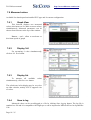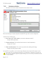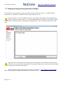
1
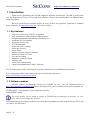
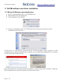
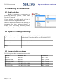
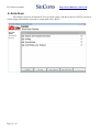
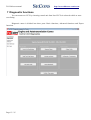
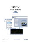
ToCOM
User manual
http://www.obdtester.com/tocom
PRELIMINARY VERSION
Copyright © 2004 – 2015 SECONS Ltd, http://www.secons.com/
All rights reserved. Version 2015-11-10
ToCOM user manual
http://www.obdtester.com/tocom
SECONS Ltd. is not connected with Toyota Motor Corporation in any way.
SECONS Ltd. is not liable for damages caused by using of ToCOM software.
Please read carefully this user manual before using the ToCOM software.
Before using the software please read license agreement.
Toyota, Lexus, and model names are registered trademarks of Toyota Motor Corporation.
Other trademarks and trade names are those of their respective owners.
Page 2 / 25
Table of Contents
1 Introduction......................................................................................................................................4
1.1 Key features..............................................................................................................................4
1.2 Software updates.......................................................................................................................4
2 ToCOM software and driver installation..........................................................................................5
2.1 Microsoft Windows operating System......................................................................................5
2.2 Microsoft Windows 8 driver installation..................................................................................6
2.3 Interface busy issue [Microsoft Windows]...............................................................................7
2.4 GNU/Linux System..................................................................................................................7
2.4.1 Requirements....................................................................................................................7
2.4.2 Setting up devices.............................................................................................................7
2.4.3 Installation.........................................................................................................................7
3 First steps..........................................................................................................................................8
4 Diagnostic connectors used in Toyota vehicles................................................................................9
4.1 OBD-II (DLC3)........................................................................................................................9
4.2 Check connector (DLC1)..........................................................................................................9
4.3 TDCL (DLC2).........................................................................................................................10
5 Connecting to control units.............................................................................................................11
5.1 Model selection.......................................................................................................................11
5.2 Toyota ECU naming terminology...........................................................................................11
5.3 Communication protocols.......................................................................................................11
6 Auto-Scan.......................................................................................................................................12
7 Diagnostic functions.......................................................................................................................13
7.1 Control Unit Identification......................................................................................................14
7.2 Read fault code memory.........................................................................................................15
7.3 Clear Fault Codes....................................................................................................................15
7.4 Freeze Frame...........................................................................................................................16
7.5 Monitor (Readiness)...............................................................................................................17
7.6 Measured values.....................................................................................................................18
7.6.1 Graph View.....................................................................................................................18
7.6.2 Display 3x3.....................................................................................................................18
7.6.3 Display list......................................................................................................................18
7.6.4 Save to log.......................................................................................................................18
7.6.5 Actuators activation.........................................................................................................19
7.7 Coding and programming functions (Utility).........................................................................20
7.7.1 Check Mode....................................................................................................................21
7.7.2 Signal check....................................................................................................................21
7.7.3 Reset memory.................................................................................................................21
7.7.4 Inspection Mode..............................................................................................................21
7.8 ECU Configuration (Customization)......................................................................................22
8 Application Settings........................................................................................................................23
8.1 Language.................................................................................................................................23
8.2 Units type................................................................................................................................23
8.3 Interface port selection............................................................................................................23
8.4 Protocol settings......................................................................................................................24
8.5 Debug functions......................................................................................................................24
9 Reporting bugs and improvement requests....................................................................................25
ToCOM user manual
http://www.obdtester.com/tocom
1 Introduction
Thank you for purchasing the ToCOM diagnostic interface and software. ToCOM is professional
tool for diagnostics of Toyota, Lexus and Scion vehicles. Please read carefully this User Manual before
using the product.
We hope you'll find our products useful. In case you have any questions, problems or feedback
please contact as at [email protected]. We're here to help!
1.1 Key features
•
•
•
•
•
•
•
•
•
•
•
•
•
•
•
•
Support for wide range of ECUs and models
Easy connection via smart USB to OBD2 interface
Designed to maintain compatibility with dealer tool
Automatic ECU recognition
Automatic vehicle scan
ECU Identification
Fault code (DTC) reading
Fault code clearing
Freeze frame
Monitor function (Engine readiness)
Measured values / live data
Live data recording
Diagnostic protocol printing
Actuator tests
Control unit customization
Control unit adjustments ("utility" function)
The ToCOM system works with Toyota/Lexus/Scion and other Toyota-Manufactured vehicles.
List of supported vehicles and control units can be found at the link below:
http://www.obdtester.com/tocom-eculist
1.2 Software updates
Software updates in diagnostic version are available for free. You can download them at
http://www.obdtester.com/downloads. Before download starts, you are asked for user name and password.
USER NAME = serial number of your diagnostic interface.
PASSWORD is blank.
The serial number can be found in settings of ToCOM after performing test interface, or on a
silver label of your diagnostic interface.
We recommend you to maintain software up-to-data, because updates provides support for new ECUs and
fix various ToCOM issues.
Page 4 / 25
ToCOM user manual
http://www.obdtester.com/tocom
2 ToCOM software and driver installation
2.1 Microsoft Windows operating System
1. Insert ToCOM installation CD to your CD-ROM drive
2. Run installation file ToComSetup.exe
3. Choose language for the installer
4. Choose your destination folder for ToCOM and click Install button and after successful
installation click Close button.
ToCOM drivers are automatically updated during the ToCOM installation. When prompted to install
„unsigned“ drivers, click on Install this driver software anyway (Microsoft® Windows® 7) or Continue
Anyway (Microsoft® Windows® XP).
Microsoft® Windows® will automatically install drivers when you plug-in the ToCOM to USB port.
Driver installation isn't required for operation on GNU/Linux system.
Page 5 / 25
ToCOM user manual
http://www.obdtester.com/tocom
2.2 Microsoft Windows 8 driver installation
Installing drivers on Windows 8 usually requires a special procedure. In such case please follow the steps
below:
1. Press Windows Key + R
2. In the window that appears, type: “shutdown.exe /r /o /f /t 00”
3. Press "OK" button
4. The System will restart to a "Choose an option" screen
5. Select "Troubleshoot" from "Choose an option" screen
6. Select "Advanced options" from "Troubleshoot" screen
7. Select "Windows Startup Settings" from "Advanced options" screen
8. Click "Restart" button
9. System will restart to "Advanced Boot Options" screen
10. Select "Disable Driver Signature Enforcement" (press number on keyboard for option shown on
screen)
11. Once the system starts, install the APM / FTDI / Arduino drivers as you would on Windows 7
Windows Vista & 7 required signed all .sys files (we use usbser.sys shipped by Microsoft with valid
digital signature). Final version of Windows 8 requires also signed .inf file (which is not in our
case). The above procedure helps to override unsigned .inf file. Once driver is installed, the
program will work properly.
Page 6 / 25
ToCOM user manual
http://www.obdtester.com/tocom
2.3 Interface busy issue [Microsoft Windows]
In case you receive error “Interface busy” while testing your interface, please make sure:
1. You're not running any modem, mobile phone, or printer monitoring application that blocks
“COM ports” from being used by other applications.
2. You're not running Hella Gutmann software on the same PC. Process called “GMPortal.exe”
prevents SECONS diagnostic applications from properly accessing the diagnostic interface. You
may temporarily resolve this problem by running “Windows Task Manager”, right-clicking on
GMPortal.exe process in “Processes” tab and selecting “End process”.
3. Software modem drivers do not block COM ports.
4. You have selected correct COM port (use “Device manager” button to find port number under
“Ports (COM & LPT)” group.
2.4 GNU/Linux System
Our diagnostic applications are tested to work under Linux. The applications can be run under
Linux, BSD or Apple OS/X on Intel x86 using Wine environment. The installer and applications perform
fully automated installation under these operating system.
2.4.1
Requirements
• Linux 2.6.x with USB support (or FreeBSD)
• USB CDC Driver
• Wine 1.0.1 or newer
Recent Debian Linux or Ubuntu meet the above requirements.
2.4.2
Setting up devices
Driver installation isn't required for operation on GNU/Linux system. Diagnostic applications
require access to /dev/ttyACMx devices from Wine environment. This can be set-up very easily using
these commands:
ln
ln
ln
ln
-s
-s
-s
-s
/dev/ttyACM0
/dev/ttyACM1
/dev/ttyACM2
/dev/ttyACM3
~/.wine/dosdevices/com5
~/.wine/dosdevices/com6
~/.wine/dosdevices/com7
~/.wine/dosdevices/com8
Diagnostic interface should be then visible from the ToCOM diagnostic application.
2.4.3
Installation
Programs can be installed by launching setup .exe file using wine, e.g. wine
ToComSetup.exe.
You can download the latest version of ToCOM at www.obdtester.com/downloads
Page 7 / 25
ToCOM user manual
http://www.obdtester.com/tocom
3 First steps
1. Connect ToCOM interface to your computer.
2. Connect ToCOM interface to OBD-II connector in the vehicle. You can use picture gallery for find
it, available from main menu – OBD-II Connector Location button
3. Set-up ToCOM application
Select Settings in ToCOM main menu and
configure interface port. After clicking on Refresh
button, software should find port to which is
ToCOM interface connected. Choose this port.
Click on Test Interface to make sure everything is
OK, you should see Serial number (now hidden in
white line).
4. Save settings and return to main menu.
5. Turn ON the ignition, but don't start the engine.
6. Select control unit by clicking on Select Control Unit button.
7. Select exact vehicle model.
8. In a new window, choose control unit to connect to.
Page 8 / 25
ToCOM user manual
http://www.obdtester.com/tocom
4 Diagnostic connectors used in Toyota vehicles
Location of OBD-II and manufacturer-specific (OBD-I) connectors is available in DLC location
database available from the ToCOM main menu.
4.1 OBD-II (DLC3)
Standard OBD2 connector is used usually since 1996 models to present.
-
1
9
Ignition +12V
-
2
10
-
-
3
11
-
Chassis Ground (CG)
4
12
-
Signal ground (SG)
5
13 TC
HS CAN High (CANH) 6
14 HS CAN Low (CANL)
ISO9141 K Line
7
15 ISO9141 L-Line
-
8
16 Battery voltage
It is possible to read blink code on older vehicles by connecting terminals TC and CG and then
turning ignition ON. Then you can read faultcode(s) from the P/S warning light on instrument cluster
(combination meter).
4.2 Check connector (DLC1)
Pin
1
Fp
2
W
Engine blink code output
3
E1
Battery -
4
Ox1
5
AB
6
TH/
O
7
8
TE1 Engine blink code
9
TE2
10
CC2 Second lambda sensor diagnostic
11
TC
Page 9 / 25
ABS L ABS, traction control, Height
Control and other system diagnostic
ToCOM user manual
codes
12
+B
13
VF1
14
VF2
15
OX2
16
TS
17
TT
18
TEM
19
IG-
20
OP2
21
OP3
22
WA
23
WB
Battery +
Ignition Pulse output
ABS K
4.3 TDCL (DLC2)
TDLC (DLC2) has same signal meaning as Check
connector.
It is possible to read blink code on older vehicles by
connecting terminals TC and CG and then turning
ignition ON. Then you can read faultcode(s) from the
P/S warning light on instrument cluster (combination
meter).
Page 10 / 25
http://www.obdtester.com/tocom
ToCOM user manual
http://www.obdtester.com/tocom
5 Connecting to control units
5.1 Model selection
Before is connection to control units (or
performing auto-scan) possible, vehicle model
selection is required.
Correct selection of vehicle model and year is
essential for proper diagnostic functions.
Incorrect model selection may result in wrong or
incomplete live data, improper function of
actuator tests and coding functions, possibly
resulting in damaged car components.
5.2 Toyota ECU naming terminology
Engine and Autotransmission
Electronic Diesel Control
Engine control unit (including diesel engines), also
controlling A/T on older vehicles (no individual AT ECU)
Combination meter
Instrument panel cluster
Automatic Trans-axle
Autotransmission
Body
5.3 Communication protocols
ToCOM supports these communication protocols:
Protocol
Diagnostic bus
Production
ISO9141
ISO9141
1991 – 2001
KWP2000-9600
ISO9141
1996 – present
KWP2000-10400
ISO9141
1996 – present
ISO15765
CAN-BUS (ISO 11898)
2005 – present
ISO15765 GW
CAN-BUS (ISO 11898)
2005 – present
Page 11 / 25
ToCOM user manual
http://www.obdtester.com/tocom
6 Auto-Scan
This function scans for all known ECUs in selected vehicle, and shows the list of ECUs present in
vehicle along with number of present or stored fault codes (DCTs).
Page 12 / 25
ToCOM user manual
http://www.obdtester.com/tocom
7 Diagnostic functions
You can connect to ECU by choosing control unit from list of ECUs in selected vehicle or autoscan listing.
Diagnostic menu is divided into three parts. Basic functions, Advanced functions and Expert
functions.
Page 13 / 25
ToCOM user manual
http://www.obdtester.com/tocom
7.1 Control Unit Identification
This function is used to display only identification data provided by the ECU, for example:
•
Calibration Identification
•
Model code
•
Engine
You can print identification by clicking Print Identification button or you can copy it to clipboard
by clicking Copy Identification.
“Save ECU information” is used to save all ECU diagnostic data (not flash memory) to a XML file. This
file is useful for further ToCOM improvements and debugging. It can also be used to recover improperly
coded ECU. It is highly recommended to save this file before performing any configuration operation on
the ECU.
Page 14 / 25
ToCOM user manual
http://www.obdtester.com/tocom
7.2 Read fault code memory
This function allows you to read and display diagnostic trouble codes saved in control unit
memory.
7.3 Clear Fault Codes
This function clears fault code stored in ECU memory.
Fault codes might appear again or under some conditions isn't possible to clear fault codes at all.
It's possible that in the presence of some faults control unit doesn't allow to clear fault codes or fault is in
no time written back to memory.
It is recommended to read memory by clicking Re-read fault codes button again.
Page 15 / 25
ToCOM user manual
http://www.obdtester.com/tocom
7.4 Freeze Frame
Freeze Frame (also known as Snapshot or Environment data) function display selected measured
values as present at occurrence of selected diagnostic fault code (DTC). This function is available from
fault codes window.
Page 16 / 25
ToCOM user manual
http://www.obdtester.com/tocom
7.5 Monitor (Readiness)
The function is available only on engine control units. Displays status of engine.
Page 17 / 25
ToCOM user manual
http://www.obdtester.com/tocom
7.6 Measured values
Available live data depend on installed ECU type and it's current configuration.
7.6.1
Graph View
This function displays two measured
values (also known as live data or sensor values)
simultaneously. Measured parameters can be
chosen from selectors at the top of the window.
Buttons – and + allow to accelerate or
decelerate speed of graph.
7.6.2
Display 3x3
For measuring 9 value simultaneously,
click on 3x3 View button.
7.6.3
Display list
To measure all available
simultaneously, click List view button.
values
The refresh rate in list display may be very slow
on older vehicles, mainly if ECU supports a lot
of values.
7.6.4
Save to log
Measured values can be saved/logged to a file by clicking Start logging button. The log file is
standard csv file and it is compatible with VagScope or can be imported to Microsoft Excel or OpenOffice
Calc.
Page 18 / 25
ToCOM user manual
7.6.5
http://www.obdtester.com/tocom
Actuators activation
This function can activate actuators and perform some actuators actions.
Please note that range of actuators depends on installed ECU type and it's current configuration.
Actuator tests are of these types:
1) Start / Stop (or ON / OFF) actuator: you can turn component on and off.
Example: MIL Light actuator
2) Actuators with states: You can choose between states to control component(s).
Example: A/F Control
3) Value-controlled actuators: You can enter any desired value within specified range.
Example: IAC Duty, Injector volume
On most ECUs it is possible to view live data using “Measured values” button while actuator is active.
Please make sure you understand consequences of activating ECU components. Also make sure
that activation conditions (engine idle, engine running, etc.) are met. Always consult all tests with
car repair handbook.
Page 19 / 25
ToCOM user manual
http://www.obdtester.com/tocom
7.7 Coding and programming functions (Utility)
This function is used to perform various operations on the control unit, such as re-coding installed
components, re-setting ECU adaptation values, performing checks, etc.
Important notice: Current ToCOM version may also display coding/utility functions that do not
apply to currently connected ECU (e.g. diesel coding functions are shown for petrol ECU). Please
consult service manual(s) before performing any coding function. We're working on resolution of this
issue.
Important notice: this function is currently under development, new functions are added as time
allows. In case you need some function that is not present in the latest version, please provide data
as described at the end of this manual.
More information about programming functions is available at www.obdtester.com/downloads .
Most common generic coding/utility functions are described below.
Page 20 / 25
ToCOM user manual
7.7.1
http://www.obdtester.com/tocom
Check Mode
This function will do the following allow 2 trip logic DTCs to be set in one trip and tighten the DTC
detection criteria so DTCs will set easier. To exit Check mode, cycle the ignition off for 20 seconds and
back on.
7.7.2
Signal check
This function will set DTCs for the system that is selected. DTCs will be erased if normal operating
conditions are confirmed.
7.7.3
Reset memory
This function is used to clear the learned memory of the ECU if the following components are replaced:
- ABS ECU
- ABS Yaw rate / G sensor
Vehicle is stopped and ignition is on
7.7.4
Inspection Mode
This function disables VSC and TRAC control systems.
Page 21 / 25
ToCOM user manual
http://www.obdtester.com/tocom
7.8 ECU Configuration (Customization)
This function is used to configure (customize) ECU behavior, enable newly installed components, etc.
ECUs that supports this feature displays a list of customizable parameters.
Please note that range of customizable parameters depends on installed ECU type and it's current
configuration.
“Save ECU information” available from “Identification” window can be used to save all ECU
diagnostic data including current configuration to a XML file. This file then can be used to recover
improperly coded ECU. It is highly recommended to save this file before performing any
configuration operation on the ECU.
Page 22 / 25
ToCOM user manual
http://www.obdtester.com/tocom
8 Application Settings
ToCom Settings is accessible from main menu.
8.1 Language
Choose program language in the drop down menu.
8.2 Units type
You can choose metric or imperial unit system for measured values.
8.3 Interface port selection
Refresh - this button refreshes COM port selection drop down list. Correct COM port number should be
already chosen after connecting diagnostic interface via USB to PC and clicking on Refresh button. If not,
choose correct COM port number from the list. It is needed in order to perform successful interface test.
Test interface – before each use of program, please test proper function of your connected interface by
clicking this button. After successful test, you can see a serial number of your interface displayed below
the COM port field, then firmware version and information about active licenses.
Activate license – this button is used for activating new license/s to use the program or special functions.
Internet connection is required. Standard license is already activated for all interfaces before purchase.
Page 23 / 25
ToCOM user manual
http://www.obdtester.com/tocom
Upgrade firmware – use this button to upgrade firmware in your diagnostic interface every time after
installing the latest software version (available at www.obdtester.com/downloads). Do not disconnect
your interface during upgrading the firmware.
Device Manager – is used to finding out correct COM port number, or to reinstall drivers. Your device
appears as “ELM-USB Interface (COMx)” under “Ports (COM & LPT)”.
Bluetooth Manager – is a preparation to upcoming bluetooth feature. The button is currently inactive.
8.4 Protocol settings
You can set various timings for each communication protocol. This is advanced feature used for example
when problems occur with connection to control unit caused by slower ECU response and the like.
Restore Defaults – this button restores all modified timings of all protocols to default values.
Changing protocol settings is not required before normal use of the program. You will be asked to
make changes by our tech. support when solving your issue at [email protected] if necessary.
8.5 Debug functions
By clicking on Save Debug button, you can capture the latest data from elapsed communication between
control unit and program into one file. Providing this file is required only by our technical support. Based
on these data, we are able to monitor the whole process of performed operation and its correctness.
Use of debug function is important for successful resolution of any program failure or verifying its
causes. For more information on how to proceed, please read the next chapter 9: Reporting bugs
and improvement requests.
Page 24 / 25
ToCOM user manual
http://www.obdtester.com/tocom
9 Reporting bugs and improvement requests
Our customers can take advantage of our full technical support for free. You can contact our technical
support at [email protected] with any technical questions and requests.
To speed up resolution of program bugs or requirements to improve the program, please prepare the
following data:
Reporting bugs
In case you encounter to failure of any program functions (eg fault codes reading/clearing, coding
functions, connecting to ECU, test interface, …), please, prepare the following data in your email:
1. Detailed description of failure
2. Vehicle description - VIN code, model, manufacture year, motorization
3. Attach Debug Log – this file captures data from the latest communication between program and
ECU, so we can detect failure causes.
4. Attach Snapshot of tested ECU (if accessible) – this file contains important information about
tested control unit
How to create Debug Log:
Once failure occurs, go back directly to settings in main
menu (do not close the program). Click on “Save Debug”
button. Name and save the file into well known directory in your
computer.
Enable “Debug mode” check box only at our special request.
How to create ecu Snapshot:
After connection to tested control unit, click on “Control
Unit Identification”. In following screen, click on “Save
ECU Information”. Choose directory to save the file and confirm.
Saving may take a few minutes.
Improvement requests
In case you miss some function or some function does not work sufficiently, please, prepare the following
data in your email:
1.
2.
3.
4.
Detailed description of your improvement request
Vehicle description - VIN code, model, manufacture year, motorization
Attach Snapshot of tested ECU – this file contains important information about tested control unit
Attach Debug Log (in case that required function doesn't work properly). This file captures data
from the latest communication between program and ECU, so we can detect failure causes.
Page 25 / 25