1
US006061067A
Ulllted States Patent [19]
[11] Patent Number:
Silva et al.
[45]
[54]
APPLYING MODIFIERS TO OBJECTS
BASED ON THE TYPES OF THE OBJECTS
[75]
Inventors: Danie] David Silva, San Rafael, Calif;
6,061,067
Date of Patent:
*May 9, 2000
5,745,122
5,796,400
4/1998 Gay et al. ............................. .. 345/433
8/1998 Atkinson et al.
. 345/441 X
5,801,709
9/1998
Suzuki et a1.
.......
. . . . . . . ..
345/433
5,818,452 10/1998 Atkinson et a1. ................. .. 345/441 X
Rolf Walter Berteig, Seattle, Wash.;
Donald Lee Brittain, Santa Barbara,
OTHER PUBLICATIONS
Califé Th0maS_DeI1e Hudson, Port
Lau—Kee et al., “VPL: An Active, Declarative Visual Pro
washington, W19; Gary 8- YOSt, San
gramming System”, IEEE, pp. 40—46, 1991.
Franclsco’ Cahf'
3D Studio Max User Manual vol. 1 and 2 and Tutorial,
[73] Assignee: Autodesk, Inc., San Rafael, Calif.
Kinetix, Autodesk Inc., pp. 1—14 through 1—15, 6—1 through
6—12, 13—1 through 13—16 and tutorial 6—10 through 6—12,
[*]
Notice:
This patent is subject to a terminal dis
claimer.
.
.
.
Primary Examzner—Mark K. Zimmerman
Attorney, Agent, or Firm—McDermott, Will & Emery
[21] Appl. No.: 08/903,958
[22] Filed:
Mar. 1996.
[57]
Jul. 31, 1997
ABSTRACT
A three dimensional (3D) modeling system for generating a
[60]
Related US. Application Data
Provisional application No. 60/025,117, Aug. 2, 1996.
7
initial de?nition of an object and a set of modi?ers. Each
[2;]
[
]
................................................... .. G06gll4ézgg
I. .
. ............................................................ ..
Fleld of Search ................................... ..
[
that may result in a Change in appearance of the Object When
R f
Ct d
e erences l e
Us PATENT DOCUMENTS
]
11/
5’49O’246
5,583,977
12/1996
5,731,819
Seidl .............. ..
modi?es some portion of the initial de?nition of the object
and produces a modi?ed de?nition. The next modi?er modi
?es the results of the previous modi?er. The results of the
last modi?er are then used in rendering processes to generate
the 3D representation. Each modi?er is associated With a
three dimensional representation so that the user can more
‘g’hlilson et a1‘ """""""""""" "
22996 132102132151"" "
modi?er modi?es some portion of the de?nition of an Object
rendered‘ The modi?ers are Ordered SO that the ?rst modi?er
345/522’ 437’ 438’ 439’ 349
56
3D representation of a modeled object on a display device of
a computer system. The modeled object is represented by an
344349
easily visualize the effect of the modi?er.
345/433
3/1998 Gagne et al. ......................... .. 345/433
16 Claims, 14 Drawing Sheets
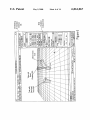
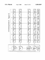
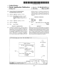
30 Modeling
File
Edit
Group
8. Animation
Interface
135
Views
O Cube
@Bnx
[M1
Length: m
Width: m]
Height: @2111
Wave
World
Space
Modifier
Lenath SegsJIIj
Width Segs: U
Height Seg: [S11
[jGeneiaie Mapping Cnoids
Seieclad
and
to
Indicator
840
U.S. Patent
May 9, 2000
Sheet 1 0f 14
6,061,067
25m
63805
8mEcw2obQz.n?e60hmEwOim
/
53Q.:0 ow?
E8 :58: N2 8.353323m:
2:
mio.cmow
8ew2.:6n5:2 o3E082
6Ec52o9mp8>0w
U.S. Patent
May 9, 2000
Sheet 2 0f 14
6,061,067
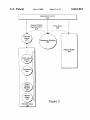
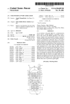
Application
Control
200
1
Derived Object
Representation
246
Rendering Pipeline
250
-
Z
Display Buffer
A
260
World Space
Modifier
240
Transform
230
Object
Space
Modi?er
220
Figure 2
Modi?er Stack
280
U.S. Patent
May 9, 2000
Q2:2 w8%52 8%25 m2
E@
Sm omw
E56gum2E
6,061,067
:2:3
Em»WMEQ
LE$Q§BW
Sheet 11 0f 14
U.S. Patent
May 9, 2000
Sheet 13 0f 14
6,061,067
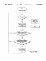
YCST
Cache Final
Channel Values
4
1360
Determine Modi?ed
Channel Values
V
1320
Stan
d——NO
odi?ed Channel Values
Stable for X Frames?
1330
Yes
ext Element Change
Modi?ed Channel Values in
Next Frame?
1340
Yes
l
Cache Modi?ed
Channel Values
1350
Figure 13
6,061,067
1
2
In one embodiment, the modi?ers are easily shared, the
APPLYING MODIFIERS TO OBJECTS
BASED ON THE TYPES OF THE OBJECTS
order of the modi?ers is easily changed, and the values
associated With the modi?ers is also easily changed. These
features provide the user With great ?exibility in modeling
RELATED APPLICATIONS
and animation.
This application claims the bene?t of US. provisional
In one embodiment, the modi?ers are associated With
three dimensional visual representations that alloW a user to
patent application No. 60/025,117, entitled, “Three Dimen
sional Modeling and Animation System,” ?led Aug. 2, 1996,
by inventors Rolf Walter Berteig, Daniel David Silva,
Donald Lee Brittain, Thomas Dene Hudson, and Gary S.
Yost, Which is incorporated herein by reference.
10
COPYRIGHT DISCLAIMER
A portion of the disclosure of this patent document
contains material Which is subject to copyright protection.
15
The copyright oWner has no objection to the facsimile
appears in the Patent and Trademark Office patent ?les or
records, but otherWise reserves all copyright rights Whatso
20
neXt intermediate channel results in that channel Will not be
diate channel results are cached.
25
BRIEF DESCRIPTION OF THE DRAWINGS
These and other features and advantages of the invention
Will become more apparent to those skilled in the art from
30
erate models of three dimensional objects using computers.
sional (3D) object and then applies various modi?cations
(e.g., stretch, bend) to that object. The modi?cations change
FIG. 2 illustrates a hoW objects are rendered in the 3D
35
?er and corresponding giZmo.
40
an object until after the modi?cation is applied to the object.
Additionally, it can be dif?cult to understand eXactly hoW a
speci?c modi?cation affects an object from the look of the
object after the modi?cation is applied. This is because it can
be dif?cult to understand the interactions betWeen various
modi?cations, already applied to the object, and the neW
modi?cation
Therefore, it is desirable to have a 3D modeling system
modeling and animation system of FIG. 1.
FIG. 3 illustrates an object.
FIG. 4 illustrates an object having an object space modi
object and vieWs the results.
One problem With such a system is that the user does not
have a good idea of hoW a speci?c modi?cation Will affect
the folloWing detailed description in conjunction With the
appended draWings in Which:
FIG. 1 illustrates a 3D modeling and animation system
according to one embodiment of the invention.
In previous systems, a user de?nes a simple three dimen
the Way the object looks. To apply a modi?cation, a user is
prompted With a dialog boX to ?ll in the values of the
modi?cation. The user then applies the modi?cation to the
may or may not be cached. In particular, in one embodiment,
if it is determined that one set of intermediate channel results
valid for a predetermined period of time, then the interme
sional modeling and animation. In particular, the invention
relates to an improved three dimensional modeling and
animation system having an object oriented architecture.
B. Related Art
Three dimensional modeling systems alloW users to gen
of that representation. Intermediate channel results are gen
Will be valid for a predetermined period of time, While the
BACKGROUND OF THE INVENTION
A. Field of the Invention
The invention relates generally to ?eld of three dimen
cached thereby increasing the speed of this embodiment. In
particular, the representation of the object is generated in
multiple channels, each channel representing some portion
erated in each channel by elements in that object’s list of
modi?ers. Depending on for hoW long these intermediate
channel results are valid, the intermediate channel results
reproduction by anyone of the patent disclosure, as its
ever.
better visualiZe and change the effect of a particular modi
?er.
In one embodiment, intermediate channel results created
during the generation of a representation of an object are
45
FIG. 5 illustrates a second object space modi?er applied
to the object of FIG. 4.
FIG. 6 illustrates changes to the modi?er stack of the
object of FIG. 5.
FIG. 7 illustrates further changes to the modi?er stack of
the object of FIG. 5.
FIG. 8 illustrates a key frame and the start of an animation
sequence.
FIG. 9 illustrates a “betWeen frame” of the animation
sequence.
that is simpler for the user to use by alloWing the user to
FIG. 10 illustrates a second key frame of the animation
better understand hoW a particular modi?cation to an object
Will affect the look of that object.
sequence.
FIG. 11 illustrates a third key frame of the animation
SUMMARY OF THE INVENTION
sequence.
FIG. 12 illustrates an eXample of the use of channels in
One embodiment of the invention includes a method of 55
generating a derived object’s representation.
generating a three dimensional (3D) representation of a
modeled object on a display device of a computer system.
The modeled object is represented by an initial de?nition of
an object and a set of modi?ers. Each modi?er modi?es
some portion of the de?nition of an object that may result in
a change in appearance of the object When rendered. The
FIG. 13 illustrates one embodiment of a method of
caching.
FIG. 14 illustrates an eXample of caching.
60
modi?ers are ordered so that the ?rst modi?er modi?es some
portion of the initial de?nition of the object and produces a
modi?ed de?nition. The neXt modi?er modi?es the results of
the previous modi?er. The results of the last modi?er are
then used in rendering processes to generate the 3D repre
sentation.
The ?gures illustrate the invention by Way of eXample,
and not limitation. In the ?gures, like references indicate
similar elements.
DETAILED DESCRIPTION
65
A. Terminology
In this description, the term “instance” means an instance
of class as in an object oriented programming language. In
6,061,067
3
4
particular, “instance” does not mean an instance as de?ned
cathode ray tube (CRT) display, ?at panel display, or some
other display device. In the example of FIG. 1, the 3D
in the 3D Studio MaxTM User Guide, Volume 1 and 2, unless
speci?cally noted. Also note that an “instance” in the object
representation of the scene 142 is shoWn in a perspective
vieW 132.
oriented sense can also be an “instance” in the 3D Studio
The 3D modeling and animation application 145 includes
data and instructions for creating 3D models, photo-realistic
still images, and ?lm quality animation. The 3D modeling
MaxTM application sense.
The term “reference” generally means a reference created
through the use of the ReferenceTarget and ReferenceMaker
classes, or the like, as described beloW.
and animation application 145 uses a process called “ren
B. System OvervieW
dering” to determine the correct display device 130 repre
One embodiment of the invention includes an apparatus
10
sentation of a modeled object on a display device of a
computer system. The description of speci?c applications is
provided only as examples. Various modi?cations to the
preferred embodiments Will be readily apparent, and the
general principles de?ned herein may be applied to other
embodiments and applications Without departing from the
sentation of the scene 142. One embodiment of the invention
includes the application 3D Studio MaxTM, available from
Autodesk, Inc. of San Rafael, Calif.
The scene 142 includes all the objects to be displayed in
the 3D modeling and animation interface 135. An object is
and method of generating a three dimensional (3D) repre
15
thus something in a scene 142. Further, an object is a model
of a physical object, such as a cylinder, tube, box or teapot,
or an object is a non-physical object used in modeling other
spirit and scope of the invention. Thus, the invention is not
objects, such as a Wave, a bomb, or a de?ector. Each object
intended to be limited to the embodiments shoWn, but is to
be accorded the Widest scope consistent With the principles
and features disclosed herein.
corresponds to a graphical representation in the 3D model
ing and animation interface 135. Of course, some objects
may not be displayed because, for example, the display
options in the 3D modeling and animation interface 135 do
C. Computer System
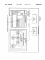
FIG. 1 illustrates a computer system 100 that can be used
to implement the one embodiment of the invention. FIG. 1
also illustrates an example of a tube as modeled by one
not alloW that particular object to be displayed, because one
object is blocking another object, or because the user has
25
embodiment of the invention. The folloWing describes the
elements of FIG. 1 and then their operation.
The computer system 100 comprises a processor 110, a
memory 140, an input device 120 and a display device 130.
requested that the object not be displayed. Objects are
described in greater detail beloW.
The scene 142 is made up of a number of nodes, such as
node 144. Each node is associated With some object. In the
example of FIG. 1, the node 144 is associated With a derived
tube 146 object. The derived tube 146 is a model of a
physical object; in this case, a tube that has been bent and
tWisted. The bent and tWisted tube is shoWn as the derived
These components can communicate With each other via a
bus 150. The memory 140 includes softWare such as the 3D
modeling and animation application 145. The 3D modeling
and animation application 145 includes, among other things,
tube’s graphical representation 134. Note the invention
alloWs for much more visually complex objects to be
a scene 142. The scene 142 includes at least a ?rst node 144,
a corresponding derived tube 146 and a tube modi?er stack 35 rendered, but for FIG. 1, an example of a relatively simple
object is described.
199. The tube modi?er stack 199 includes a tube master 190,
a bend modi?er 192, and a tWist modi?er 194. The display
The derived tube 146 has a modi?er stack, labeled as tube
modi?er stack 199. The tube modi?er stack 199 is a sim
device 130 displays the 3D modeling and animation inter
face 135 Which shoWs a 3D representation of the derived
pli?ed example of a modi?er stack. The modi?er stack is
tube 146 and the corresponding tube modi?er stack 199.
The computer system 100 includes an IBM compatible
described in greater detail beloW. The tube modi?er stack
personal computer, available from Hewlett-Packard, Inc. of
Mountain VieW, Calif. In another embodiment, the computer
bend modi?er 192 and the tWist modi?er 194. The tube
199 includes the tube master 190 (a parametric object), the
master 190 includes a parametric de?nition of a tube, eg a
tube has an inner radius, an out radius and a height. The bend
able from Apple Computer, Inc. of Cupertino, Calif. a 45 modi?er 192 modi?es the de?nition of the tube so that the
tube Will appear bent. The tWist modi?er 194 modi?es the
SparcStationTM Workstation, available from Sun
de?nition of the bent tube so that the bent tube is also
Microsystems, Inc., of Mountain VieW, Calif. and a Work
tWisted. HoW the modi?ers Work in connection With the
station from Silicon Graphics, Inc. of Mountain VieW, Calif.
master objects is described in greater detail beloW. HoWever,
In one embodiment, the computer system 100 executes an
operating system such as WindoWs 95 TM or WindoWs NTTM,
importantly, the use of modi?er stacks, in one embodiment
system 100 includes one of a MacintoshTM computer, avail
of the invention, provides the user With previously
unequaled ease of use and ?exibility in 3D modeling and
animation.
available from Microsoft, Inc. of Redmond, Wash.
The computer system 100 need only have some type of
processor 110 for executing instructions and manipulating
memory 140 includes one or more of a random access
The folloWing describes the general operations in the
computer system 100 used in the rendering process. The
computer system 100, using the processor 110 and the
memory 140, executes the 3D modeling and animation
application 145 Which renders a three-dimensional (3D)
memory, a read only memory and a hard disk memory.
The input device 120 alloWs the user to interact With the
part of the rendering process, the derived tube 146 provides
data. In one embodiment, the processor 110 includes a
distributed processing system such that processing is done
by a number of netWorked microprocessors.
55
The memory 140 stores data and instructions. The
representation of the scene 142 on the display device 130. As
3D modeling and animation application 145. The input
a parametric de?nition of a bent and tWisted tube for use by
device 120 includes one or more of a keyboard, a mouse, and
the 3D modeling and animation application 145. In this step,
a trackball. Importantly, the input device 120 includes some
device alloWing the user to interact With the 3D modeling
and animation application 145.
The display device 130 displays the 3D modeling and
animation interface 135. The display device 130 includes a
the derived tube 146 accesses the tube modi?er stack 199 to
65
generate the parametric de?nition of the bent and tWisted
tube. The 3D modeling and animation application 145 uses
the parametric de?nition and various rendering techniques to
generate the derived tube’s graphical representation 134.
6,061,067
5
6
The 3D modeling and animation application 145 then causes
The ReferenceTarget class supports the broadcast of mes
the display device to display the perspective vieW 132,
including the derived tube’s graphical representation 134.
sages to all referring reference maker objects about changes
to that reference target object. As With the Animatable class,
Thus, given a scene With a derived object, the computer
system 100 can render a representation of that object.
used in the application, instances of these classes’ subclasses
no instances of ReferenceMaker or ReferenceTarget are
The above has described an overvieW of a computer
are used instead.
system that supports 3D modeling and animation using
In one embodiment of the invention, references support a
modi?er stacks. The neXt section describes the class hierar
technique called laZy evaluation. LaZy evaluation increases
the performance of the 3D modeling and animation appli
chy used in the 3D modeling and animation application 145
that enable the use of modi?er stacks. FolloWing the neXt
section is a description of the hoW these classes are used
10
together in the application.
evaluations until speci?cally requested.
D. Objects and Their Relation to Scenes
In one embodiment of the invention, the 3D modeling and
animation application 145 has an object oriented design.
Thus, the application has a class hierarchy that supports
inheritance. This section describes the class hierarchy used
15
coordinate space of the second object to scale the ?rst object.
LinkedXForms are described beloW). This relationship is
archy in one embodiment of the 3D modeling and animation
application 145. Each of the classes is described beloW.
established via a reference from the ?rst object to the second
object. If the data in the second object is changed, then the
second object Will broadcast the change to the ?rst object. In
laZy evaluation, the ?rst object does not recalculate any
TABLE 1
Animatable
ReferenceMaker
25
Modi?er
TriObj ect
i. Animatable Class
The Animatable class is the superclass of all the animat
able classes. Although no instances of Animatable are used,
instances of the Animatable’s subclasses include methods
that support the animation of an instance of that particular
subclass. Also, the Animatable class includes a class iden
changed values (e.g., its geometry parameters) until the ?rst
object is speci?cally requested (e.g., a request to provide a
derived object representation, described beloW). In laZy
evaluation, the ?rst object merely marks its dependent
values as no longer valid. Thus, the ?rst object does not
precompute the neW values until it needs to provide these
values.
Object
GeometricObject
SimpleObject
PatchObject
ParticleObject
SimpleParticle
ShapeObject
SplineShape
SimpleSpline
LinearShape
SimpleShape
WorldSpaceModi?erObject
SimpleWorldSpaceModi?erObject
The folloWing describes an eXample of laZy evaluation.
Assume that to properly render a ?rst object, that ?rst object
must receive data from a second object (e.g., the ?rst object
includes an instance of a LinkedXForm Which uses the local
to create modi?er stacks. Table 1 illustrates the class hier
ReferenceTarget
BaseObject
cation 145. The purpose of laZy evaluation is to reduce the
number of unnecessary calculations by not performing any
iii. BaseObject
The BaseObject class includes the methods for providing
a three dimensional graphical representation of an object on
the display device 130. The BaseObject class includes
methods for providing different display methods (e.g.,
35
bounding boX, Wireframe) for each of its subclasses. In one
embodiment, these display methods are overridden by
equivalently named methods in the BaseObject’s subclasses.
iv. Modi?er
The Modi?er class includes the methods for modifying
objects during the rendering process. Instances of the Modi
?er’s subclasses provide a set of very poWerful and ?exible
features that greatly enhance the usability of the 3D mod
eling and animation application 145. Each instance of a
Modi?er subclass has methods for causing a particular
45 modi?cation of an object, such as a bend or a tWist.
ti?er and associated properties.
ii. ReferenceMaker & ReferenceTarget
The ReferenceMaker class and the ReferenceTarget
classes Work together to support references betWeen objects
Modi?ers change the look of an object by, for eXample,
changing the object’s vertices or the object’s topology.
in a scene. A reference Within a scene occurs When one
object depends upon another object for rendering. For
provides a user With a virtually endless number of combi
nations. Modi?ers can also be shared through references.
eXample, one embodiment of the invention alloWs different
objects (eg tWo derived tubes) to share the same master
speci?c types of objects. For eXample, in this embodiment,
object. In this eXample, the master object becomes the target
instances of the Bend class can modify geometric objects
Modi?ers can be stacked together so that the output of one
modi?er is fed into the input of another modi?er. This
In one embodiment, each Modi?er subclass modi?es only
of references from the objects. The reference alloWs a scene 55 and shape objects While instances of the EditSpline class can
to be rendered and alloWs for the use of modi?ers by
only modify shape objects.
There are tWo main subclasses of Modi?er: ObjectSpace
multiple objects. As is described beloW, this use feature
Modi?er and WorldSpaceModi?er. These classes are
provides a user With signi?cant bene?ts over previous
described neXt.
systems. The reference also alloWs changes in the master
object to be broadcast to any objects that are referring to that
V. ObjectSpaceModi?er
master object. The ReferenceMaker class includes the meth
The ObjectSpaceModi?er class is a subclass of the Modi
ods for indicating that a particular instance depends on
another instance. The ReferenceMaker class also includes
methods for receiving messages from reference target
objects When changes are made to that reference target
object. The ReferenceTarget class includes the methods for
indicating that a particular instance is a target of a reference.
?er class. The ObjectSpaceModi?er class is the superclass of
the object space modi?er classes. Before further describing
65
the class, the various coordinate spaces relevant to one
embodiment of the invention are described.
Different spaces are used in one embodiment of the
invention to differentiate different sets of spatial coordinate
6,061,067
8
7
systems. In one embodiment of the invention there are tWo
OptimiZe—reduces the number of faces and vertices in an
relevant spatial coordinate systems, object space and World
object. The purpose of OptimiZe is to simplify the geometry
and increase the speed of rendering While maintaining an
space.
Object space is the coordinate system unique to each
acceptable image.
object in the scene 142. In one embodiment, every object has
a local center and coordinate system de?ned by the location
XForm—acts as a transform for all or a portion of an
object but is evaluated as a modi?er. The importance of the
order of execution of modi?ers and transforms is described
in greater detail beloW.
and orientation of the object’s pivot point. The local center
and coordinate system of an object combine to de?ne that
object’s object space.
World space is the universal coordinate system used to
track objects in a scene 142. World space relates the coor
LinkedXForm—Works in the same Way as XForm eXcept
10
object.
dinates de?ning an object to the other objects in the scene
142. An object in a scene is located in World space by that
EditSpline—changes the splines, segments and vertices of
a shape object. Shape objects are described beloW in con
object’s position, rotation and scale (its transforms).
Returning to the description of the ObjectSpaceModi?er
class, instances of the subclasses of ObjectSpaceModi?er
that the LinkedXForm uses the coordinate system of another
15
junction With the description of the Object class.
EXtrude—creates a 3D object by sWeeping a shape along
modify an object in object space. For example, a bend is an
object space modi?er that causes an object’s de?nition to
change so that some portion of the object is bent relative to
a straight line. Lathe—creates a 3D object by revolving a
shape along an aXis.
some other portion of that object.
The folloWing describes the types of object space modi
?ers available in one embodiment of the invention. Object
space modi?ers can be divided into general, specialiZed and
Before describing World space modi?ers, a description of
a method of interacting With object space modi?ers is
provided. One embodiment of the invention not only alloWs
edit shape modi?ers. The general object space modi?ers
by directly entering the values of the parameters, but also
have real-World equivalents and are relatively simple to
understand. In one embodiment, the general object space
(1) Manipulating Object Space Modi?ers
a user to change the parameters of an object space modi?er
25
modi?ers include: bends, ripples, skeWs, tapers, tWists, and
Waves. In this embodiment, the special modi?ers include:
displace, noise, and optimiZe. Also in this embodiment, the
edit shape modi?ers include edit splines, eXtrudes and
lathes. In one embodiment, Bend, Ripple, Skew, Taper,
alloWs the user to manipulate a 3D representation of the
modi?er.
In one embodiment, the 3D representation of the modi?er
is called a giZmo. The giZmo is a Wireframe representation
of that giZmo’s modi?er. A giZmo acts like a mechanical
apparatus that transfers the modi?cation to the object that
TWist, Wave, Displace, Noise, OptimiZe, XForm,
giZmo is attached to. That is, by changing the giZmo, the user
is changing the values of the parameters of the modi?er. A
LinkedXForm, VolumeSelection, EditSpline, EXtrude and
user can move, scale and rotate a giZmo as is done With any
Lathe are all subclasses of the superclass ObjectSpaceModi
other object.
?er.
Bend—produces a uniform bend in an object’s geometry.
The angle and direction of the bend is set as Well as the bend
aXis. The bend modi?er has a limit value that limits the bend
to a particular section of an object’s geometry. Ripple—
produces a concentric rippling effect in an object’s geom
etry. The siZe of the Waves of the ripple are set. Ripple has
a corresponding modi?er in the World space.
Wave—produces a Wave effect in an object’s geometry.
The siZe and phase of the Wave is set. One embodiment of
the invention supports a decay value that decreases or
increases the siZe of the Wave. Wave also has a correspond
35
accessible by a user. For eXample, a modi?er may have a
center, de?ned by an {X, y, Z} coordinate, a scale along each
aXis, and a rotation along each aXis. This is a great deal of
information. HoWever, by providing the user With a three
dimensional representation of this modi?er information, the
user can quickly visualiZe this information and change it,
thereby changing these values and in turn changing the effect
45
ing World space modi?er.
SkeW—produces a uniform offset in an obj ect’s geometry.
of the modi?er on the object.
In one embodiment, World space modi?ers also have
giZmos. In another embodiment, an instance of a World
space modi?er uses a World space modi?er object to change
the parameters of the World space modi?er.
vi. World Space Modi?er
Like instances of the ObjectSpaceModi?er class,
instances of the WorldSpaceModi?er class affect the appear
ance of other objects. The difference being that World space
modi?ers affect objects in World space coordinates. Also like
the ObjectSpaceModi?er class, WorldSpaceModi?er has a
The amount and direction are set for each instance of skeW.
A skeW’s effect can also be limited so that only a portion of
an object is skeWed.
Taper—produces a tapered contour by scaling one end of
an object’s geometry. Each taper instance has values for the
amount of tape and curve of the taper on tWo sets of aXes.
The taper’s effect can also be limited to a section of the
object’s geometry.
In one embodiment, the giZmo represents parameters of a
modi?er that are not otherWise easily de?nable and/or
55
number of subclasses that can be instanced to modify objects
in different Ways.
TWist—produces a tWist like a screW’s thread in an
One or more objects are modi?ed by a World space
object’s geometry. Each instance of TWist has values for the
modi?er by binding those objects to the World space modi
?er. In one embodiment, the binding process is performed by
angle of the tWist on any of three aXes, and a bias that
compresses the threads relative to the pivot point of the
object. The tWist’s effect can also be limited to a section of
creating a reference betWeen the World space modi?er and
each object that is bound to that World space modi?er. A
the object’s geometry.
World space modi?er has no effect on an object in a scene
Displace—reshapes the geometry With a variable force.
One embodiment of the invention has a corresponding
Displace class that is a subclass of WorldSpaceModi?er.
Noise—simulates random motion in an animated object.
Noise also produces fractal effects that are useful in creating
142 that is not bound to the World space modi?er.
Importantly, When multiple objects are bound to the same
World space modi?er, the World space modi?er’s parameters
terrain features, for example.
65
affects all the objects equally. HoWever, each object’s dis
tance from, and spatial orientation to, the World space
modi?er can change the World space modi?er’s effect.
6,061,067
9
10
Because of this spatial effect, simply moving an object
spline-based shapes like a heliX. Shape objects are not
directly renderable in one embodiment. The shape objects
through the World space can change the World space modi
?er’s effect. This last feature provides a user With a powerful
tool in animations. For example, to shoW a dolphin
need to ?rst be modi?ed before they are renderable.
swimming, a user need only model the dolphin and then bind
but is still visible to the user. A World space modi?er object
is like a giZmo for an object space modi?er. The World space
modi?er object provides a visual representation of a World
space modi?er that alloWs the user to bind an object to the
World Space Modi?er Object—is not a renderable object,
the dolphin to an instance of a Wave World space modi?er.
As the dolphin object translates through the World space, the
dolphin Will be modi?ed by the Wave to appear to be
corresponding World space modi?er.
sWimming. Additionally, an object can be bound to multiple
World space modi?ers.
In one embodiment, each World space modi?er includes a
10
graphical representation of itself As noted above, this
graphical representation is a giZmo in one embodiment, and
in another embodiment, this graphical representation is an
instance of a subclass of the Object class.
The folloWing is a list of subclasses of
WorldSpaceModi?er, in one embodiment:
alWays sees a derived object, even if no modi?ers are
applied to an object. The reason for this is that the derived
15
Bomb—eXplodes a geometric object into individual faces
one embodiment of the invention and is described in greater
detail beloW.
middle of a Waterfall.
25
place class eXcept the effect is in World space.
Gravity—simulates the effects of gravity on particles
generated by a particle system object. Gravity instances are
directional. To create a Waterfall With a rock in the middle,
instances of Gravity and De?ector classes can be combined.
Ripple—acts much like the ObjectSpaceModi?er Ripple
and BaseObject.
E. Pipeline for Rendering
Wave—acts much like the ObjectSpaceModi?er Wave
class eXcept the effect is in World space.
35
generated by a particle system object.
As noted above, each Modi?er subclass knoWs Which
objects it can modify. In the above embodiment, the Bomb,
FIG. 2 and the folloWing describe hoW objects in a scene
142 are rendered in one embodiment of the 3D modeling and
animation application 145. So as not to obscure this embodi
ment of the invention, FIG. 2 has been simpli?ed. The
folloWing ?rst describes the elements of FIG. 2 and then the
operation of those elements.
Display, Gravity, Ripple and Wave classes modify geometric
objects. The De?ector, Displace, Gravity and Wind modi?
ers modify particle system objects.
One embodiment of the invention includes a plug-in
architecture that alloWs additional object space and World
space modi?ers to be added to the 3D modeling and ani
mation application 145.
vii. Object
The above class hierarchy illustrates only one class hier
archy. Other embodiments include other class hierarchies.
For example, in one embodiment, the classes under the
ShapeObj ect are moved under the GeometricObj ect class. In
another embodiment, the methods in the Animatable, Ref
erenceMaker and ReferenceTarget classes are combined into
the BaseObject class. In another embodiment, the Referen
ceTarget is a superclass of the ReferenceMaker. In another
embodiment Written in a language that supports multiple
inheritance, ReferenceMaker does not inherit from
Animatable, nor does BaseObject inherit directly from
ReferenceTarget, hoWever the Modi?er class and the Object
class multiply inherit from the Animatable, ReferenceTarget
class eXcept the effect is in World space.
Wind—simulates the effect of Wind bloWing particles
object not only ensures that a particular object is correctly
rendered, but also that an appropriate cache is maintained for
that particular object. The caching abilities of the derived
objects is an important performance enhancing feature of
that over time become disjoint in space. Thus, the Bomb
subclass is particularly useful in animations.
De?ector—acts as a shield to repel the particles generated
by a particle system object. A de?ector can be used to
simulate pavement being struck by rain, or a rock in the
Displace—acts much like the ObjectSpaceModi?er Dis
Derived Object—includes a list of modi?er objects and a
pointer to the master object. In rendering a scene, a user
45
FIG. 2 includes an application control module 200, a
derived object 270, a modi?er stack 280, a master object
210, an object space modi?er 220, a transform 230, a World
space modi?er 240, a rendering pipeline 250 and a display
buffer 260. These elements Work together to render a graphi
cal representation of the derived object onto the display
device 130.
As noted above, the term object refers to something in the
scene 142. In one embodiment, all objects are de?ned by
The application control 200 controls the operation and
three general properties: a collection of creation parameters,
a pivot point, and a bounding boX. The properties describe
the form, local origin, initial orientation, and the eXtent of an
interaction betWeen the elements of FIG. 2. In one
object.
important is that there is some method of controlling the
various elements in FIG. 2.
embodiment, the application control 200 includes the 3D
Studio MaXTM core softWare architecture. HoWever, What is
The Object class is the superclass of all the different types
of objects in a scene. In one embodiment, the Object class
has the folloWing subclasses: GeomObject (geometry
object), ShapeObject, WorldSpaceModi?erObject, and Deri
55
vedObject.
The GeomObject class is the superclass of basic render
When a user creates an object in a scene.
able objects, such as tubes, cylinders, boXes, polyhedra,
spheres, torus, and cones. One embodiment of the invention
includes the folloWing geometric object categories.
Standard Primitives—3D geometric objects such as Box,
Sphere, and Cylinder.
Patch Grids—are 2D surfaces.
Particle Systems—are animated objects that simulate rain,
snoW, dust and similar collections of small objects.
Shapes—include 2D objects line lines and donuts and 3D
The derived object 270 is part of a scene 142 (not shoWn)
and is responsible for ensuring that a modi?ed object is
properly rendered. The derived object is an instance of the
DerivedObject class. The derived object instance is created
65
In one embodiment, each derived object 270 maintains a
modi?er stack 280. In one embodiment, the modi?er stack
280 includes a list of modi?ers (e.g. object space modi?er
220 and World space modi?er 240), a transform, and a
pointer to a master object 210. In another embodiment, the
derived object 270 maintains a reference to the master object
210, a reference to the transform 230, and a list of modi?ers.
HoWever, What is important is that the derived object 270
maintains the information necessary to generate a descrip