1
!#"$&%
!(')!
15 August 1999
ii
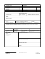
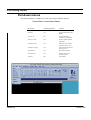
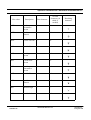
CLASSIFICATION
CATEGORY
1.Config controlled for approval
1.Unclassified
x
2.Config controlled for review
2.Industry
3.Non config controlled for review
x
3.Restricted
4.For information
4.Confidential
CONTRACT
Contract number: GSAF-CD-ROVI-34
Programme: GSAF
Issuing organisation: DASA
Work package number:
Contractual date:
11QAP-BM, 11QAR-BM & 11QAS-BM
Issue 2, April 1996
TITLE:
GSAF GWDU, FWDU & MMIS Development & Maintenance
FWDU User Manual
Issue 2.2
Issue date: 15 August 1999
INTERNAL REFERENCE NUMBER:
R:/projects/114-FWDU/UM/Cover.fm
NUMBER
of pages: NA
of annexes: NA
SUMMARY: The purpose of this document is to describe how the FWDU Software is used. The manual is an edited
version of the SAMMI User Manual 3.0
HOST SYSTEM
HARDWARE
EQUIPMENT
MEDIA
SOFTWARE
LANGUAGE CODE:
ENG
Nature: M.O.
HP LaserJet
Nature and type: DD
Identification:
Name: FrameMaker for Windows
Version: 5.1.1
KEY WORDS:
FWDU
Mission Database
User Manual
Prepared by: Nazzareno Straccia
Approved by: Poul Erik Holmdahl
Authorised by: Allan Mahler
CCB date:
.
FWDU
ROVSING A/S
UM-114-002-ROV
Issue 2.2
User Manual
15 August 1999
iii
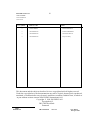
DISTRIBUTION LIST
USER SYMBOL
o For information
x For action
User Symbol
Address Codes
Name
o
DASA-RIO62
Ralf Zimmermann
o
ROVSING A/S
Poul Erik Holmdahl
o
ROVSING A/S
Nazzareno Straccia
o
ROVSING A/S
Project Library
This document and the subjects described in it are copyrighted with all rights reserved.
Under the copyright laws, the documentation may not be copied, photocopied, reproduced,
translated, or summarised to any electronic medium or machine readable form, in whole or
in part without written consent of ROVSING International A/S.
Copyright © 1999, ROVSING A/S
Dyregårdsvej 2
DK-2740 Skovlunde
Denmark
.
FWDU
ROVSING A/S
UM-114-002-ROV
Issue 2.2
User Manual
15 August 1999
iv
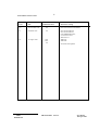
DOCUMENT CHANGE LOG
Issue
Date
Modified Sections
2.0
14 November 1996
All
First Issue based on FrameMaker
2.1
28 March 1999
All
DN-114-002-UM-010,
DN-114-002-UM-011,
COL-RIBRE-SPR-5250,
CCN#2 and CCN#3
IRN-8010 1/A
2.2
15 August 1999
7-198
7-340
SPR-5973
SPR-6009
All
.
FWDU
ROVSING A/S
UM-114-002-ROV
Reason For Change
footer has been updated
Issue 2.2
User Manual
15 August 1999
Table of Contents
Table of Contents
I
I
Introduction to the FWDU ........................................................................ 11
FWDU Format Editor ......................................................................... 11
Welcome to FWDU
11
FWDU Text Editor .............................................................................. 12
Tools Interacting with the FWDU ....................................................... 12
Who can use this manual ........................................................................ 12
How to use this manual ........................................................................... 14
Basics of the Format Editor ..................................................................... 14
Windows ............................................................................................ 16
Formats .............................................................................................. 16
Static components ............................................................................. 16
Dynamic components ........................................................................ 16
Data access types .............................................................................. 18
Application Programming Interface (API) ........................................... 18
For more information ............................................................................... 20
Planning the interface .............................................................................. 21
Getting Started
21
Data display/control functions ............................................................ 22
Display methods and types ................................................................ 23
Helpful presentation aids ................................................................... 27
Creating a user-friendly interface ....................................................... 28
Prototyping/review cycles .................................................................. 29
Format naming/tracking ..................................................................... 29
Starting the FWDU Format Editor ........................................................... 30
A quick tour of the Format Editor ............................................................. 31
Using the keyboard ............................................................................ 31
The mouse ......................................................................................... 32
Mouse movement ............................................................................ 32
Cursor shapes ................................................................................. 33
Mouse buttons ................................................................................. 33
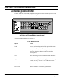
The Format Editor Control panel ........................................................ 35
Pull-down menus ............................................................................... 36
The Drawing Area ($fb-bkgd) ............................................................. 39
Moving panels .................................................................................... 39
Zooming the Drawing Area ................................................................ 39
Notes on panning and zooming ......................................................... 41
Other visual elements ........................................................................ 42
Dialog boxes ................................................................................... 42
Pop-up option lists ........................................................................... 43
General guidelines for using the Format Editor ....................................... 43
Creating new formats ......................................................................... 44
FWDU
ROVSING A/S
UM-114-002-ROV Issue 2.2
User Manual
15 August 1999
II Table of Contents
Creating dynamic fields (DFDs) with the Icon Palette ..................... 44
Creating dynamic fields (DFDs) with the Add DFD option ............... 45
Saving and testing a format ............................................................. 46
Viewing or changing existing formats ................................................. 46
Viewing and modifying the Format Description panel ..................... 47
Inserting UNIX files into the MDB .................................................... 47
Modifying static background objects ................................................ 47
Modifying dynamic fields (DFDs) ..................................................... 47
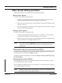
Other format editing operations .......................................................... 49
Moving static objects ....................................................................... 49
Deleting static objects ...................................................................... 49
Adding static objects and dynamic fields (DFDs) ............................ 49
Viewing dynamic fields (DFDs) ........................................................ 49
Copying formats ................................................................................. 50
Deleting formats ................................................................................. 50
Quitting the Format Editor ........................................................................ 50
Learning the Format Editor
51
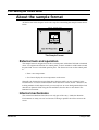
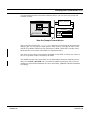
About the sample format .......................................................................... 52
External look and operation ................................................................ 52
Internal mechanisms .......................................................................... 52
What you will learn ................................................................................... 54
Lesson 1 – Building a format .............................................................. 54
Lesson 2 – Using Sammi to test the format ....................................... 54
Lesson 3 – Modifying the format ........................................................ 54
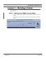
Lesson 1 – Building a format ................................................................... 55
Part 1 – Starting the FWDU Format Editor ......................................... 55
Creating a format ............................................................................. 56
Entering data in the Format Description pane ................................. 57
Part 2 – Setting colors and adding text labels .................................... 59
Setting default colors ....................................................................... 59
Setting the fill pattern ....................................................................... 60
Adding text ....................................................................................... 60
Part 3 – Changing the font style ......................................................... 62
Part 4 – Creating a Real
Dynamic Field Definition (DFD) .......................................................... 63
Entering data on the DFD Display panel ......................................... 64
The Real Display Panel ................................................................... 65
Attaching MDB End Items as Data Sources ................................... 66
Completing the data entry process for the Real DFD ..................... 67
Part 5 – Creating a Meter
Dynamic Field Definition (DFD) .......................................................... 68
Entering data on the DFD Display Panel ......................................... 69
Entering data on the Meter Display Panel ....................................... 70
Completing the data entry process for the Meter DFD .................... 71
FWDU
ROVSING A/S
UM-114-002-ROV Issue 2.2
User Manual
15 August 1999
Table of Contents III
Lesson 2 – Using Sammi
to test the format ..................................................................................... 71
Part 1 – Testing the format ................................................................ 71
Part 2 – Changing the format and retesting ....................................... 72
Lesson 3 - Drawing static
background objects ................................................................................. 72
Part 1 – Changing the format ............................................................. 72
Part 2 – Setting up the default drawing styles .................................... 73
Setting the line orientation ............................................................... 74
Setting the Snap/Grid function ........................................................ 74
Setting the fill style .......................................................................... 76
Setting the line style ........................................................................ 77
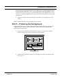
Part 3 – Drawing the “facing plate” .................................................... 78
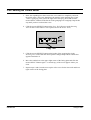
Part 4 – Drawing the background objects .......................................... 79
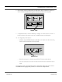
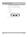
Part 5 – Finishing the background ..................................................... 81
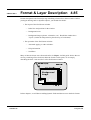
Format & Layer Description
85
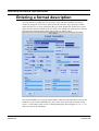
Entering a format description .................................................................. 86
Defining window size and position .......................................................... 90
Window position (X/Y location) .......................................................... 91
Window size (width/height) ................................................................ 91
Restricting access (security) ................................................................... 92
Linking formats through paging ............................................................... 93
Creating on-line help ............................................................................... 94
Adjusting the window
background color ..................................................................................... 94
Using background images ....................................................................... 94
Accepted image formats .................................................................... 95
Scaling an image ............................................................................... 95
Re-touching images ........................................................................... 95
Creating your own bitmapped images ............................................... 95
Importing the background image ............................................................. 96
Importing a movable static image ............................................................ 97
Specifying an application type ................................................................. 97
Entering a layer description ..................................................................... 99
Introduction ............................................................................................ 103
Drawing Methods
103
Drawing tools available ......................................................................... 104
Before you begin drawing ...................................................................... 106
Importing a format ............................................................................ 106
Aligning objects to a grid .................................................................. 106
Setting the Snap and Grid function spacing .................................. 107
Turning the Snap and Grid functions on and off ........................... 108
Selecting colors using the
Color Selection Display panel .......................................................... 108
FWDU
ROVSING A/S
UM-114-002-ROV Issue 2.2
User Manual
15 August 1999
IV Table of Contents
Selecting colors using the Color Palette ........................................... 109
Selecting font styles ......................................................................... 110
Selecting line styles .......................................................................... 111
Setting the current line style defaults ............................................. 112
Line fill (Solid, Dashed, Double-Dashed) ....................................... 112
Line cap (Butted, Projecting, Rounded) ......................................... 113
Line joint (Beveled, Rounded, Mitered) ......................................... 114
Dash pattern .................................................................................. 114
Line thickness ................................................................................ 114
Arrowhead settings ........................................................................ 115
Constraints .................................................................................... 115
Selecting fill styles ............................................................................ 117
Setting the current fill style defaults .................................................. 118
Available fill styles (None, Solid, Stippled) .................................... 118
Fill rule (Even/Odd, Winding) ......................................................... 119
Fill pattern (Stippled) ..................................................................... 119
How to draw objects .............................................................................. 119
Arcs/Wedges .................................................................................... 120
Circles/Ellipses ................................................................................. 122
Splines (open/closed) ....................................................................... 123
Lines (single and multiple-segment) ................................................. 125
Polygons ........................................................................................... 126
Rectangles ....................................................................................... 127
Text .................................................................................................. 128
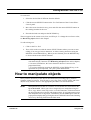
How to manipulate objects ..................................................................... 129
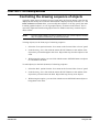
Controlling the drawing sequence of objects .................................... 130
Grouping objects .............................................................................. 131
Ungrouping objects .......................................................................... 132
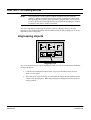
Resizing objects ............................................................................... 133
Resizing dynamic fields .................................................................... 134
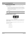
Changing points in objects ............................................................... 134
Copying objects or groups ................................................................ 135
Moving objects or groups ................................................................. 136
Deleting objects or groups ................................................................ 137
Deleting all objects ........................................................................... 137
Rotating & flipping (or mirroring) objects .......................................... 138
Changing spline-to-line or line-to-spline ........................................... 140
Adding/deleting arrowheads ............................................................. 141
As you work... ........................................................................................ 142
Recoloring objects ............................................................................ 142
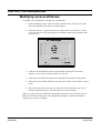
Modifying a single attribute ............................................................... 143
Modifying several attributes .............................................................. 144
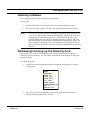
Undoing mistakes ............................................................................. 145
Redrawing/cleaning up the Drawing Area ........................................ 145
FWDU
ROVSING A/S
UM-114-002-ROV Issue 2.2
User Manual
15 August 1999
Table of Contents V
Scaling or shifting the entire format ................................................. 146
Special effects and
advanced methods ................................................................................ 147
Using scanned images ..................................................................... 147
Converting static objects to dynamic objects ................................... 147
Using composites ............................................................................. 147
Creating composites ..................................................................... 147
Retrieving composites ................................................................... 148
Deleting composites ...................................................................... 149
Dynamic Field Description
151
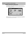
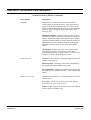
General procedures ............................................................................... 152
Setting operational preferences ....................................................... 154
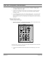
Adding a new dynamic field ............................................................. 157
Add DFD option ............................................................................. 157
Display Palette option ................................................................... 160
Read DFD Lib option ..................................................................... 162
Changing existing dynamic fields ..................................................... 163
Deleting dynamic fields .................................................................... 164
Moving dynamic fields ...................................................................... 165
Copying dynamic fields .................................................................... 166
Entering dynamic field entries ............................................................... 167
Defining the display type and data access type ............................... 171
Specifying refresh rate and type ..................................................... 174
Defining size and position ................................................................ 174
Sizing a new dynamic field ...................................................................... 175
Resizing dynamic fields ................................................................. 176
Creating on-line help ........................................................................ 178
Selecting a security level (restricting access) .................................. 178
DFD libraries ......................................................................................... 179
Creating DFD libraries ..................................................................... 179
Using the DFD library ....................................................................... 179
Deleting DFD libraries ...................................................................... 181
General features .................................................................................... 183
Display Types
183
Multiple values ................................................................................. 186
Sammi user entry ............................................................................. 187
Runtime annotations ........................................................................ 188
Runtime keys ................................................................................... 190
Border styles .................................................................................... 191
Lookup tables and indexing ............................................................. 191
Entering a Command ............................................................................ 195
Sammi Commands .......................................................................... 196
Onboard - Predefined Commands ................................................... 196
Onboard - Software Commands ...................................................... 196
FWDU
ROVSING A/S
UM-114-002-ROV Issue 2.2
User Manual
15 August 1999
VI Table of Contents
Display type reference ........................................................................... 198
Alarm (optional) ..................................................................................... 201
Display type specifications ............................................................... 202
Bar ......................................................................................................... 204
API information ................................................................................. 204
Display type specifications ............................................................... 205
Barchart ................................................................................................. 209
API information ................................................................................. 210
Display type specifications ............................................................... 211
Barchart variables display type specifications .................................. 217
Curve Sets ............................................................................................. 221
Custom Time ......................................................................................... 222
Display type specifications ............................................................... 223
Dynamic Objects .................................................................................... 225
Number of objects ............................................................................ 225
Grouping Dynamic Objects .............................................................. 226
Dynamic Object tables ..................................................................... 226
Table lookup .................................................................................. 227
Value substitution .......................................................................... 227
Table field definitions ..................................................................... 228
Display type specifications ............................................................... 231
Equation ................................................................................................. 233
Display type specifications ............................................................... 235
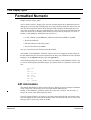
Formatted Numeric ................................................................................ 238
API information ................................................................................. 238
Display type specifications ............................................................... 239
General Action Button (GAB)/Button ..................................................... 240
Functions .......................................................................................... 241
Characteristics .................................................................................. 242
Labels ............................................................................................... 243
API information ................................................................................. 243
Runtime annotations ........................................................................ 244
Linking to function keys .................................................................... 244
Display type specifications ............................................................... 245
General Action Button Grouping ............................................................ 250
Display type specifications ............................................................... 251
Graphic Data Field ................................................................................. 256
Display type specifications ............................................................... 257
Graphs (Plot and Trend) ........................................................................ 260
General ............................................................................................. 260
X & Y Axis ........................................................................................ 260
Sizing ................................................................................................ 261
Zoom ................................................................................................ 261
Double-buffering ............................................................................... 261
FWDU
ROVSING A/S
UM-114-002-ROV Issue 2.2
User Manual
15 August 1999
Table of Contents VII
Step Display/Step Fraction .............................................................. 261
Individual curve specifications ......................................................... 263
API information ................................................................................ 263
Plot display type specifications ........................................................ 264
Trend display type specifications ..................................................... 268
Line Chart Variables Display specifications ..................................... 271
Integer ................................................................................................... 274
Display type specifications ............................................................... 274
Menu ..................................................................................................... 276
Menus used as options .................................................................... 277
Command entries for menus used as options ................................. 278
Display type specifications ............................................................... 278
Static menu display type specifications ........................................... 279
Standard menu ................................................................................ 281
Dynamic menu ................................................................................. 282
Meter/Gauge ......................................................................................... 283
API information ................................................................................ 284
Display type specifications ............................................................... 285
Meter, Fixed-Scale Linear ..................................................................... 290
API information ................................................................................ 291
Display type specifications ............................................................... 292
Meter, Moving-Scale Linear .................................................................. 297
API information ................................................................................ 297
Display type specifications ............................................................... 298
Object Icon ............................................................................................ 303
Display Type Specifications ............................................................. 304
Option List ............................................................................................. 308
Display type specifications ............................................................... 310
Pie Chart ............................................................................................... 311
API information ................................................................................ 312
Pie Chart Display type specifications ............................................... 313
Pie Chart Variables Display type specifications ............................... 314
Legend Display specifications .......................................................... 318
Real ....................................................................................................... 321
Display type specifications ............................................................... 321
Region ................................................................................................... 323
API information ................................................................................ 323
Display type specifications ............................................................... 323
Scrollbar ................................................................................................ 325
Display type specifications ............................................................... 326
Select List .............................................................................................. 328
Select List used as an Option List .................................................... 328
Command entries for Select Lists
used as Option Lists ........................................................................ 329
FWDU
ROVSING A/S
UM-114-002-ROV Issue 2.2
User Manual
15 August 1999
VIII Table of Contents
Optional components ....................................................................... 329
Display type specifications ............................................................... 330
Static Select List Item: Command Entries ....................................... 334
Slider ...................................................................................................... 336
API information ................................................................................. 336
Display type specifications ............................................................... 337
Symbol Table ......................................................................................... 339
Display type specifications ............................................................... 339
Tabular ................................................................................................... 342
Data Definition Record ..................................................................... 342
Display type specifications ............................................................... 343
Text ........................................................................................................ 345
Text Browser/Browser ........................................................................... 346
API information ................................................................................. 346
Display type specifications ............................................................... 347
Static Browser Data Display panel ................................................... 351
Text Table .............................................................................................. 352
Display type specifications ............................................................... 352
Data Access Types
355
Curve Set ............................................................................................... 356
LCL (Local) ............................................................................................ 356
NOP (No operation) ............................................................................... 357
Time ....................................................................................................... 357
Universal ................................................................................................ 358
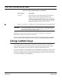
Using runtime keys ................................................................................ 360
Creating runtime keys ...................................................................... 361
Substituting variables for runtime keys ............................................. 362
Combining runtime keys into sessions ............................................. 362
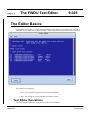
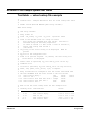
The Editor Basics ................................................................................... 365
Text Editor Operations ..................................................................... 365
The FWDU Text Editor
365
Hints and Tricks ................................................................................ 366
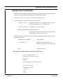
Supported End Items ........................................................................ 366
Equipment Constraints ..................................................................... 367
Example of a Equipment Constraint End Item ............................... 367
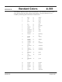
Standard Colors
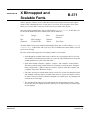
X Bitmapped and
Scalable Fonts
369
371
Formats ............................................................................................ 375
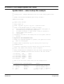
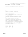
Standard Command File
375
Examples .......................................................................................... 378
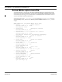
Format Editor option menu file ......................................................... 380
Runtime Environment option menu file ............................................ 381
FWDU
ROVSING A/S
UM-114-002-ROV Issue 2.2
User Manual
15 August 1999
Table of Contents IX
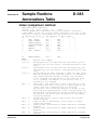
Index comparison method ................................................................ 383
Sample Runtime
Annotations Table
383
LEX method ..................................................................................... 385
Pixel Measurements
Conversion Factors
387
389
Shifting ............................................................................................. 391
Shifting and Masking
391
Masking ............................................................................................ 392
Alarm Formats and Colors
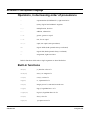
Equation Language
393
395
Operators, in decreasing order of precedence ................................ 396
Built-in functions ............................................................................... 396
Built-in constants .............................................................................. 397
Statements and control flow ............................................................. 397
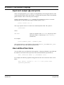
Input and output (@ and print) ......................................................... 398
User-defined functions ..................................................................... 398
Sample Bitmap Symbol File
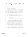
Sample Dynamic Object Table
Sample Symbol/Text Tables
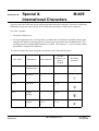
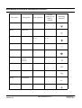
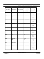
Special &
International Characters
MDB/SAMMI Types
399
401
403
409
419
Log Files .......................................................................................... 421
Internal Errors - Log Files
Glossary
Index
FWDU
ROVSING A/S
421
423
427
UM-114-002-ROV Issue 2.2
User Manual
15 August 1999
X Table of Contents
FWDU
ROVSING A/S
UM-114-002-ROV Issue 2.2
User Manual
15 August 1999
Chapter 1
Welcome to FWDU
1-11
Introduction to the FWDU
The FWDU (Flight Window Definition Utility) is an interface design system for use with the
Runtime Environment. You can use the FWDU to create new on-board interfaces, or modify
existing ones.
The FWDU consists of two tools:
• FWDU Format Editor - for editing Synoptic Displays
• FWDU Text Editor - for editing text files used by the Format Editor
FWDU Format Editor
The FWDU Format Editor (often just called the FWDU as this is the main tool) is a modification of the
commercial tool Sammi from Kinesix. The Format Editor is used for creating and editing synoptic displays. The major new features in the FWDU compared to the standard Sammi product are:
• The FWDU interfaces to the MDA. File saves and read are directed to the mission data-
base application.
• The FWDU checks each display for consistency errors and reports them at save time.
• The FWDU can preview displays.
• The FWDU handles On-board Commands and Pre-defined Commands.
• The FWDU generates cross reference lists in the MDB.
• The FWDU automatically files out several attributes in each DDO based on the attached
End Item.
• The FWDU can generate display reports.
• The FWDU has an improved user interface.
• The FWDU automatically files out the logical server fields.
More details about the FWDU Format Editor can be found in the remainder of this document.
FWDU
ROVSING A/S
UM-114-002-ROV Issue 2.2
User Manual
15 August 1999
1-12 Welcome to the Format Editor
FWDU Text Editor
The FWDU Text Editor is a basic editor for writing and modifying text files used by the FWDU.
The Text Editor reads/saves the files from/into the mission database. The Text Editor has some intelligent functionality which at save time and at read time checks the text and modifies it if necessary.
The basic functionality of the FWDU TExt Editor is described in Chapter 9 The FWDU
Text Editor.
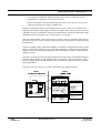
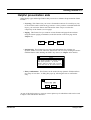
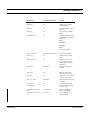
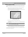
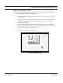
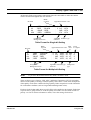
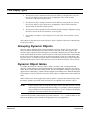
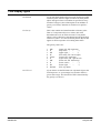
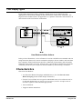
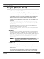
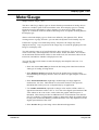
Tools Interacting with the FWDU
The FWDU is a part of the Columbus Ground System and it is used for creating and editing onboard synoptic displays used for controlling and commanding the Columbus Orbiting Facility
(COF).
B ased M issio n
D atabase
FW DU
USER
FW D U S co pe
F light D ata
G eneration
G round S ystem /S upport S oftw are
O n-B oard S ystem
O n-B oard
M ass
M em ory
MCD
O n-B oard
E xecutor
A stro naut
The FWDU creates and stores synoptic displays in the Mission Database (MDB). The synoptic displays are hereafter read from the MDB, converted, and placed on the COF on-board laptop called
LAPAP. The displays are fed with data from the on-board data management system (DMS) via
the logical server called the MCD (Mission Control and Display). Commands triggered by the astronaut are read from the display by the MCD and passed on to the COF systems.
Who can use this manual
This manual assumes that you have a basic understanding of computers, networking, and
interfaces. This includes anyone who has used window-based computer software and
understands good user interface design. It also includes anyone who has used a workstation
on a network and understands how networking allows users to share information and
resources. If you have experience using drawing programs, you will find the Format
Editor’s drawing features familiar and easy to use.
As a format designer, you may have to work closely with, or consider the needs of, these
other Sammi users:
FWDU
ROVSING A/S
UM-114-002-ROV Issue 2.2
User Manual
15 August 1999
Welcome to the Format Editor 1-13
• Sammi End User. The person for whom you are designing a user interface. The
Sammi end user will use your formats in the Runtime Environment to handle a realworld
application. The Sammi end user is typically a person who understands the application
itself but not necessarily the technical aspects of computers and workstation environments. Therefore, all of your planning and design should be carried out with the
goal of making the end-user interface as intuitive and user-friendly as possible. As
part of the
format design, you or someone in your organization may have to create special enduser
documentation for the Sammi user.
• Sammi System Administrator. The person who has installed the system and main-
tains security levels, passwords, etc. The System Administrator is typically a person
with a
solid understanding of the workstation environment (including setting up the
X Window System), who may be able to help you understand many of the technical
aspects of
Sammi.
• Sammi API Programmer. The person who works with the Application Program-
ming
Interface (API) to create data servers and applications that will feed data into and
out of the Sammi user interfaces you design. This person must be an experienced
C-language programmer, but does not have to be an expert in networking or
X Window System applications. You will need to work closely with this person to
develop the data access portions of your user interface.
In some organizations, each of these jobs is held by a separate person with separate skills.
If your talents are broad enough and the workload is small enough, you may be called on
to handle some of these jobs yourself, in addition to format design.
FWDU
ROVSING A/S
UM-114-002-ROV Issue 2.2
User Manual
15 August 1999
1-14 Welcome to the Format Editor
How to use this manual
This manual is designed to provide all the information you will need to operate the Format
Editor. The chapters are summarized below:
• Chapter 1, Welcome to the Format Editor, explains the basic operation and concepts
related to Sammi and the Format Editor.
• Chapter 2, Getting Started, explains how to plan the interface design, how to start
and stop the Format Editor, and how to operate the Format Editor.
• Chapter 3, Learning the Format Editor, provides step-by-step lessons that help you
use the Format Editor to create a sample format.
• Chapter 4, Format & Layer Description, explains how to enter the general
specifications for a format.
• Chapter 5, Drawing Methods, provides step-by-step procedures for using the
Format Editor’s Drawing Tools to draw background objects.
• Chapter 6, Dynamic Field Description, provides step-by-step procedures for creat-
ing or modifying dynamic fields built into a format.
• Chapter 7, Display Types, explains how to enter specifications for each display type
associated with a dynamic field.
• Chapter 8, Data Access Types, explains how data access works and how to create
data access descriptions that can link dynamic fields to live data.
• Appendices, provide additional reference information you may need to understand
technical aspects of the Format Editor.
We recommend that you start by reading Chapter 2 carefully, then follow the lessons in
Chapter 3 for a quick introduction to using the Format Editor. Once you understand how
the Format Editor works, you can use the remaining chapters and appendices for reference
on specific functions.
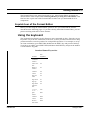
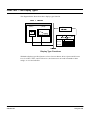
Basics of the Format Editor
The Format Editor helps make difficult computing tasks simple by letting you design and
build graphical user environments that present data on the computer screen in intuitive,
easy-to-read formats. For example, you could use the Format Editor to design:
• Computerized maps that show current activity at various locations around the
country or around the world.
• Animated drawings, schematics, or blueprints with imbedded “live data” that
change dynamically over time.
FWDU
ROVSING A/S
UM-114-002-ROV Issue 2.2
User Manual
15 August 1999
Welcome to the Format Editor 1-15
• Control panels with knobs and buttons that really “work” to control processes,
instruments, or equipment at any remote location.
• Improved computer interfaces that merge data from a wide variety of sources on a
computer network into a simple, readable form.
Display formats built with the Format Editor become active when you use them in the
Runtime Environment, subsequently referred to as Sammi. Since Sammi operates under the
X Window System, each display format is presented inside a movable window that can be
manipulated with a pointing device, such as a mouse or trackball.
Thus, the Format Editor is the display builder used to create user interfaces and Sammi is
the display manager used to provide runtime operation of the interfaces created using the
Format Editor.
The most valuable feature of the Format Editor is its ability to simplify the interface design
process. The Format Editor lets you scan in maps, drawings, or other background images;
add drawn objects to the background image; and then add dials, graphs, or other built-in
display elements.
In the past, up to 90 percent of the effort required to develop mouse-and-window interfaces
was taken up by the design and building of the user interface. The Format Editor makes
interface design simple, so that designers can concentrate on what they do best– creating
better applications.
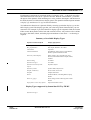
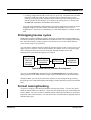
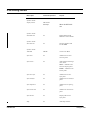
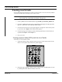
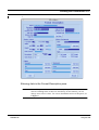
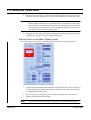
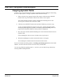
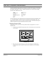
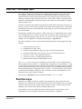
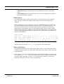
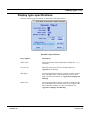
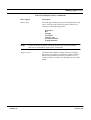
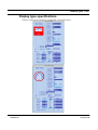
The basic concepts of how you use the Format Editor are illustrated below:
./0 0 1
./0 0 1
Format Editor
B 8 E A 4 7 ; 6 2 = E ?3 7?8 @
HU IK PJ ] Y K L I M N O
J PQ O I J NI I S T
UH IV JI K P ^K P L I IQ M N O
23 45 536 6 78
U V W X P Q X U L Y N V Z P N Y J U P Q K O [ I R IJ N J \ WI R R S T
; 5 @ 4 A ?= B ?6 CD ; 6 2 = E ?3 7?8 @ F; B ; G
9 :
9
9
9
; 4 74 < = = 6 2 2 ; 6 >?@ ?7?8 @
; E 4 _ ?@ ` a 8 8 C2
c
b 9c
99 9 9 9
Format Description
lmn
d e j fd fg kh i
Window
Background
Image
o d s e pt f u k q e g v h w r i
Background
Objects
Sammi
- colors
- background image
* +,-
* Display Type Definition
Sammi
Dynamic Field Description (DFD)
0
100
} } ~
} ~
x y r d j ze { zk |i w
Speed
33.5
44.2
123.5
Dynamic Fields
How should dynamic field look?
- size
- color, font
- position
- display type*
How should dynamic
- data access type**
- refresh rate/type
- runtime annotations
- entry confirmation
field work?
- display/enter
- logging
- help, security
- option list
How should data be processed?
- max/min values
- conversion factor
- shifting/masking
- lookup tables, etc.
**Data Access Definition
Drawing Tools
Draw objects:
- circle/ellipse
- rectangle
- polygon, arc
- text, etc.
FWDU
ROVSING A/S
How should display type look?
- labels
- color
- tick marks
- scale
UM-114-002-ROV Issue 2.2
Manipulate objects:
- group/ungroup
- move/copy/flip
- fill/color/thickness
- font, etc.
What is the source of data?
- Logical server (RPC, node, etc.)
- Database, record, element
- Number of values
User Manual
15 August 1999
1-16 Welcome to the Format Editor
Windows
The Runtime Environment displays data using the standard movable windows environment
of the X Window System. Each window may include static components that do not change
and dynamic components that are changed by incoming data or by Sammi users.
Formats
For each window that will appear in the Runtime Environment, you create a corresponding
format using the Format Editor. The format serves as the basic blueprint for the final Sammi
window, including its size, color, position, and all of its components. The Format Editor
allows you to construct formats using a set of Drawing Tools, Drawing Area, and a series
of ready-made display components, as described next. The format itself does not become
an active window until Sammi is started and an add-window command for your format is
issued.
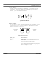
Static components
Each format that you create using the Format Editor may include static visual elements that
are not designed to move or change when they appear in Sammi. There are two types of
static components:
• Background images are graphical images derived from various sources such as
business logos, maps, photographs, and blueprints that have been scanned into the
computer using a digital scanner. Typically, a background image serves as a backdrop for the information being presented in a window. For example, you could scan
in a picture of a control panel, then overlay various dynamic components such as
dials and push buttons (described next).
• Static objects include text labels and geometric shapes such as circles, ellipses, arcs,
curves, lines, polygons, and rectangles. You can use these shapes to construct
simple diagrams or pictures of process components that will help make the interface
more visually useful to the operator. With the Format Editor, you draw most static
objects with a few clicks of the mouse. Though these objects normally are static
within a display, they can also be given dynamic properties using the Dynamic
Object display type discussed in Chapter 7.
NOTE:
Static objects are drawn on top of the background image.
Dynamic components
You can create formats which include dynamic components that reflect changes in their
states during runtime (that is, while Sammi is running). For example, a format can include
a gauge that represents the changing of the pressure reading in a boiler, or a push button
that lets the Sammi user send a warning signal (or message) to another workstation simply
by clicking on the button.
FWDU
ROVSING A/S
UM-114-002-ROV Issue 2.2
User Manual
15 August 1999
Welcome to the Format Editor 1-17
Each dynamic component is contained inside of a dynamic field — a physical area of the
format that has been reserved for a specific function. With the Format Editor, you define
all aspects of the dynamic field, including size, color, position, data inputs, and function on
the DFD (Dynamic Field Definition) Display panel. The dynamic field description includes
a display type and data access type as discussed below.
You indicate the function of a dynamic field by selecting a particular display type on the
DFD Display panel. The display type that you select has general characteristics you can
customize. For example, if you select the Meter display type for a dynamic field, the Format
Editor creates the dynamic field to look and work like a meter. All you have to do is define
the colors, dial limits, labels, and other physical attributes of the meter — no drawing is
required.
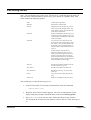
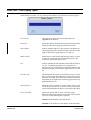
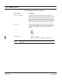
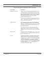
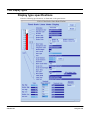
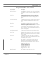
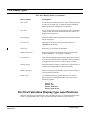
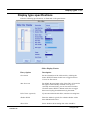
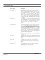
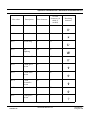
Summary of Available Display Types
Dynamic Function Required
Display Type(s) Used
Area definition
Region
Bar graphs/Charts
Bar Graphs, Barcharts, Pie Charts
Calculations
Equations
Command initiation
Push Buttons, Object Icons, Toggle Buttons,
Menus, Option and Selection Lists
Data entry and/or display
Reals, Integers, Text, Custom Time, Text
Browser, Formatted Numeric Output, Sliders,
Tabulars
Data scrolling
Scrollbars
Dynamic messages
Text Table
Dynamic movement of static
objects
Dynamic Objects
Dynamic symbols
Symbol Table, Object Icons
Graphs, standard x/y
Plots, Trends, Curve Sets
Graphics
Graphic Data Field
Menus
Pulldown Menus, Cascading Menus, Popup
Menus
Meters or gauges
Meter, Gauge, Fixed or Moving Scale Linear
Meters
Popup lists to select entry options
Option and Selection Lists
Display Types supported by Sammi but NOT by FWDU
Dynamic messages
FWDU
ROVSING A/S
Alarm
UM-114-002-ROV Issue 2.2
User Manual
15 August 1999
Welcome to the Format Editor 1-18
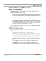
Data access types
Most dynamic fields provide a direct link to “live” data. For example, a Meter DFD might
be linked to a pressure sensor on a boiler and show the current pressure as a reading on its
dial. This linking of dynamic fields to live data is called data access. Sammi provides three
major types of data access (for a complete list, refer to Chapter 8):
• Local. The dynamic field receives data from local sources, such as other dynamic
fields. For example, a General Action Button dynamic field might be designed to
send a message to a Text dynamic field in the same format or other formats on other
workstations running Sammi.
• Time. The dynamic field gets the current time and/or date from the system clock.
This is only used with the Custom Time dynamic field.
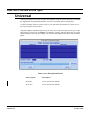
• Universal. The dynamic field is linked to a remote source via the Sammi
Application Programming Interface (API).
The FWDU supports the attachment of by having a “End Item” buttons whenever a data
source can be attached. The type of the end item is read automatically from the Mission
Database Application (MDB). When attaching an End Item a browser can be opened so that
the user can select valid End Items which are valid in the context. For each dynamic filed
different sets of End Items can be attached. How to attach the End Items is described
together with each dynamic field.
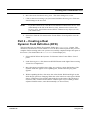
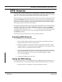
Application Programming Interface (API)
Most computer programs are designed to work with a certain set of data that the program
itself builds and maintains. Sammi is different, however, because it accesses data from other
sources that may exist in a wide variety of locations on a network, including:
• Databases
• Other applications
• On-line instruments
Since the variety and location of data sources is so diverse, Sammi is designed to interface
to each individual installation using the optional Application Programming Interface (API),
a set of standard functions designed to handle communication between Sammi and remote
data sources. Part of the API, however, must be modified by a computer programmer
experienced in C-language.
Different applications can be set up to handle data transfer to and from Sammi and remote
processes. For example, one API data server might provide access to NDBM databases,
and another to SQL databases, and an API application could be written to channel the flow
of data from on-line instruments into certain Sammi windows.
FWDU
ROVSING A/S
UM-114-002-ROV Issue 2.2
User Manual
15 August 1999
Welcome to the Format Editor 1-19
NOTE:
FWDU
ROVSING A/S
The LAPAP software provides a data server which is called the MCD. The logical server name is however FWDU_SERVER. A preview data server is provided with the FWDU so that synoptic displays can be previewed. This data
server just provides the displays with random data inside the provided limits.
UM-114-002-ROV Issue 2.2
User Manual
15 August 1999
Welcome to the Format Editor 1-20
For more information
If you need more information about Sammi and the Format Editor, please consult these
related manuals available from Kinesix.
• System Administrator’s Guide. This manual explains the installation of Sammi,
system setup, control of system processes, administrative commands, and utility
functions; typically your System Administrator will perform these functions.
• Command Reference. This manual lists all commands required for operating the
Sammi system.
• Application Programming Interface (API) Guide. This manual explains how
C-language programmers can use the optional Applications Programming Interface
(API) to create their own applications for exchanging data between customerdeveloped software and Sammi.
A supplemental manual, the Contributed Software Guide, introduces a sample database
and data server that can be used to provide test data for Sammi windows designed using the
Format Editor.
Most of these manuals are available at any site where Sammi is installed. If they are not,
please contact Kinesix for information at (713) 953-8300.
FWDU
ROVSING A/S
UM-114-002-ROV Issue 2.2
User Manual
15 August 1999
CHAPTER 2
Getting Started
2-21
This chapter explains how to get started using the FWDU Format Editor (sometimes simply
called the FWDU and other times Format Editor - depending on the context), including how
to:
• Plan the interface design,
• Start and stop the FWDU Format Editor,
• Use the mouse and windows with the FWDU Format Editor, and
• Create, view, modify, copy, and delete formats.
Before reading this chapter, you should understand the basic concepts and terminology
presented in Chapter 1.
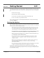
Planning the interface
Before using the FWDU Format Editor to design new Sammi formats, you must first decide
how you want the ultimate product to look and what it should accomplish. Your planning
should consider a number of different factors:
• What display/control functions should be included? Who will be the users of this
new system? What types of data are essential to them? Where will the data come
from? What types of control and updating functions should these users have?
• How should data be represented? Should data values be displayed literally (perhaps
as numbers or text) or represented graphically (as a gauge needle position)?
• What presentation aids should be used? Could the user benefit from buttons, men-
us, on-line help, or other available features?
• How should the interface be structured? Should data be presented in a single
window or in a series of “pageable” windows which show different levels or
categories of data?
• What are your prototyping/review requirements? Will the design need to be ap-
proved by managers, committees or end users? Will you need working
demonstration models?
• How will formats be tracked? Each format is stored as a file on disk. Do you want
to adopt a standard file-naming scheme for keeping track of formats?
Each of these considerations is discussed in more detail on the following pages. The
following discussion should help you pinpoint what you are trying to accomplish and how
the Format Editor can help.
FWDU
ROVSING A/S
UM-114-002-ROV Issue 2.2
User Manual
15 August 1999
2-22 Getting Started
NOTE:
If you only want to learn program operation right now, without getting into the
details of design planning, you can skip the rest of this section and return to it
later when you are ready to start creating your own production formats.
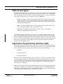
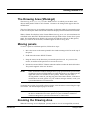
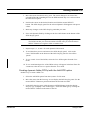
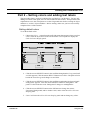
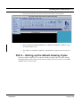
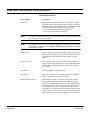
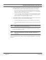
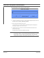
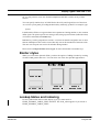
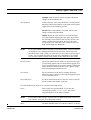
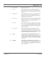
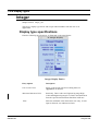
Data display/control functions
The main purpose of Sammi is to provide the user with visual access and control over a wide
variety of network resources. One of the first decisions, therefore, should involve the types
of data to be displayed and the types of control functions to be provided for users. Sammi
provides access to a wide variety of network resources, including:
• Databases. Sammi can display data from any type of database (hierarchical,
relational, custom, etc.) and let the user make changes to the data that are written
directly back into the database.
• Applications. Sammi can exchange data and commands with remote applications.
Thus, users can use Sammi to start remote applications and to receive data or
commands back from them.
For example, by pressing a key or clicking the mouse, the Sammi user might start a remote
application that reads in data from on-line instruments and issues alarms based on high or
low instrument readings. When the alarm appears in the Sammi window, the user might
push another key (or use the mouse to click on a button) to access a database and call up a
list of persons to be notified about the alarm condition.
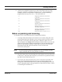
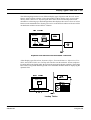
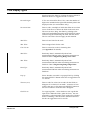
Communication between Sammi and remote data sources is handled through the
Application Programming Interface (API). For this reason, you will need to coordinate the
format design process closely with API programmers to make sure all of your planned data
display and control requirements can be met.
Instruments
Instruments
Sammi
input to Sammi
Dynamic
Field
commands to/from Sammi
Data Server
Dynamic
Field
Application
Instruments
Database
Instruments
read/write
access
Local Area
Network
Typical Sammi Input/Output
FWDU
ROVSING A/S
UM-114-002-ROV Issue 2.2
User Manual
15 August 1999
Getting Started 2-23
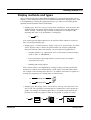
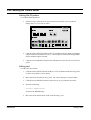
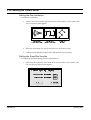
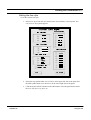
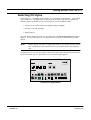
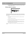
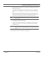
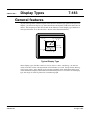
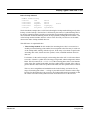
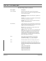
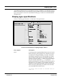
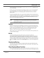
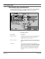
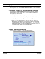
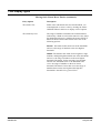
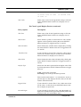
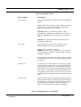
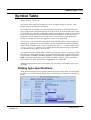
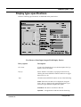
Display methods and types
Once you know what type of data should be displayed, you must decide the best way to
display it. The Format Editor provides several different methods for displaying data. Each
is accomplished by selecting the appropriate display type when you are setting up the
dynamic field for that data in the Format Editor.
• Display types: Real, Text, Integer, Custom Time, and Tabular. You can create data
fields that allow user entries and/or display of remote data. Any data displayed is
shown “literally,” without being converted or interpreted. For example, if the
incoming data value is 12, the number 12 is displayed.
12
12
You can also provide input/output access to ASCII text data with the Text Browser
Data Input/Output display type.
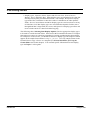
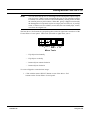
• Display types: Formatted Numeric Output, Object Icon, Symbol Table, Text Table,
Alarm, Dynamic Object. Sammi can present almost any concept symbolically.
Instead of showing a data value literally, you can represent it graphically as:
— Graphic symbols (e.g., open/closed valve, on/off switch) or short messages
(such as “OK” or “PROBLEM”).
— Lists of messages concerning alarms or system events (for example,
“System Error at 145").
— Blinking and moving objects.
Each of these effects is accomplished by creating a lookup table that specifies the
characters or symbols to be substituted for certain ranges of incoming data values.
For example, if the incoming data value is 12, it could be converted to a symbol or a
message by comparing it to a lookup table, as shown below:
12
lookup table
12
lookup table
"OK"
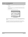
• Display types: Bar, Gauge, Meter, Linear Meters, Moving-scale and Fixed-scale,
Plot, Trend. You can display incoming data as a readout on a scale or points on a
graph. For example, an incoming data value of 12 could be represented by the
position of a needle on a gauge, a slider on a bar graph, or a point on a curve:
Trend Example
100
80
12
12
60
12
50.0
25.0
40
0.0
20
1:30
2:00
2:30
3:00
3:30
0
FWDU
ROVSING A/S
UM-114-002-ROV Issue 2.2
User Manual
15 August 1999
2-24 Getting Started
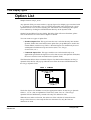
• Display types: Equation, Menu, Option and Selection Lists, General Action
Buttons, Scroll and Slider Bars. Some display types are not linked to live data, but
instead perform purely mechanical functions. For example, the Equation display
type works like a calculator to show the results of calculations on other dynamic
fields; General Action Button and Menu display types are used to activate a variety
of functions; Scroll Bar display types are used with other dynamic fields to move
through data that is larger than one screen; and Option List display types allow end
users to make entries to a data field without typing.
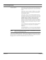
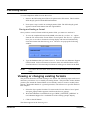
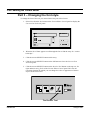
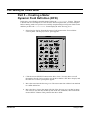
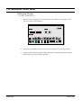
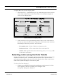
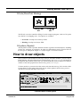
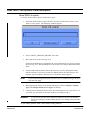
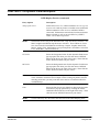
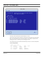
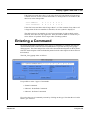
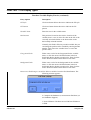
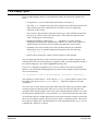
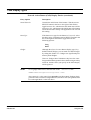
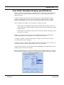
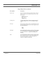
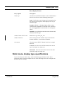
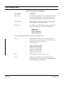
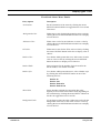
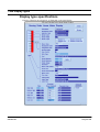
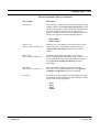
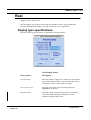
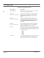
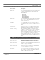
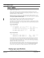
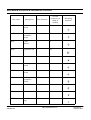
The following chart, Selecting Data Display Options, lists the appropriate display types
to be used for various desired effects. Each item in the list includes the name of a sample
format that you can use as a model or a template for viewing or producing the desired effect.
For example, to create a meter, you should use the Meter display type, an example of which
appears in the sample format named sample_meter. View any sample format in the
Format Editor or copy it for use as a template (see General Guidelines for Using the
Format Editor later in this chapter). You can find specific information on each display
type in Chapter 7 of this guide.
FWDU
ROVSING A/S
UM-114-002-ROV Issue 2.2
User Manual
15 August 1999
Getting Started 2-25
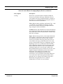
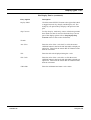
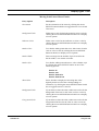
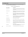
Selecting Data Display Options
If Your Objective Is To...
Use This Display Type:
Display current system time and date
Custom Time
(demo_ssdtg)
Display editable text data
(static text, files, etc.)
Text Browser
(sample_brwser)
Display data and/or allow user entries
Real, Integer, Text
(sample_litrl)
Display mixed data
(text and numeric)
Formatted Numeric &
Tabular
(sample_litrl)
Display symbols that indicate the
nature of incoming data
Symbol Table
(sample_sfs)
Display a message that changes based
on incoming data
Text Table
(sample_afs)
Perform spreadsheet-like calculations
on other dynamic fields
Equation
(sample_eqn)
Make background objects rotate,
blink, change appearance
Dynamic Objects
(sample_dobj)
Show data as a needle moving
across a dial
Meter, Gauge,
Fixed-scale
Linear Meter
(sample_meter)
Show data as a moving scale
across a reference point
Moving-scale
Linear Meter
(sample_msl)
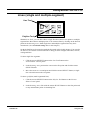
Show data as a growing and
shrinking column on a bar graph
Bar
(sample_bar)
12:30:34 9-14-94
12.0
OK
12
OFF
PROBLEM
60.00
(x=5y)
¯¯ ³ ± ° ² ² °
¶·¸µ´ ²²²
® © © ¬ © « © ¹ ²ª © ¨ © ¦ § ¡ ¢ £ ¤ £ ¥ ¤
100
80
60
40
20
0
FWDU
ROVSING A/S
UM-114-002-ROV Issue 2.2
User Manual
15 August 1999
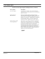
2-26 Getting Started
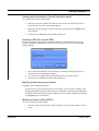
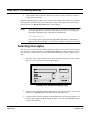
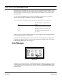
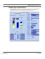
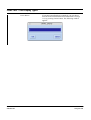
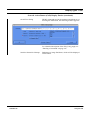
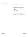
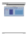
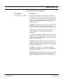
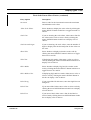
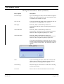
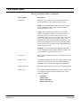
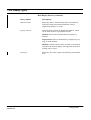
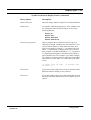
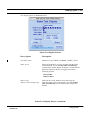
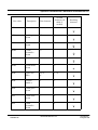
Selecting Data Display Options
87
If Your Objective Is To...
Use This Display Type:
Allow analog input of numeric
data using a sliding control
Slider
(sample_slider)
¿
23
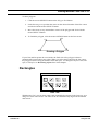
Trend Example
50.0
Plot data points vs. time
Trend
(sample_trend)
25.0
0.0
1:30
2:00
2:30
3:00
3:30
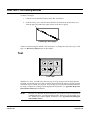
Á
Pressure vs. Flow & Temp
Plot multiple data sets
Plot
(sample_plot)
À
20.0
F
l
o
w
10.0
0.0
80.0
T
e
m 70.0
p
60.0
1.0
1.5
2.0
2.5
3.0
Pressure
Provide symbols that can be used
to activate Sammi functions or system
functions as well as to reflect their
current state
Object Icon
(sample_icon)
Provide different button types that
can be used to activate Sammi functions
or system functions. These buttons can
also have different states
General Action Buttons
(sample_gabs)
Provide mutually exclusive or
non-mutually exclusive groupings
of buttons that can be used to activate
Sammi functions or system
functions
General Action
Button Groupings
(sample_gabutton)
Provide a menu bar or pop-up
menu that activates Sammi functions
or system functions
Menu
(sample_menu)
Ä
 sÃÃtartÃ
ÂstÄopÃ
Å
exit
Pop-Up Menu
ÂsÃtartà  sà tÄop exitÃ
Æ Ç È È É Ê ËÌ Í Î Ï
Menu Bar
Provide a pop-up option list
to allow user entries without keyboard
input required
Option List
(sample_menu)
Dynamic Field
(Integer)
12
Ð
11 - start
12 - fast
13 - slow
14 - stop
Cancel
Dynamic Field
(Option)
Provide a scrollbar for scrolling
other dynamic fields
Scrollbar
(ndbm01)
º »
¼
12.3
2.5
341.0
12.3
»½ ¾
»
FWDU
ROVSING A/S
UM-114-002-ROV Issue 2.2
User Manual
15 August 1999
Getting Started 2-27
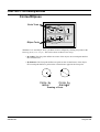
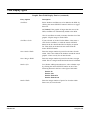
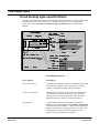
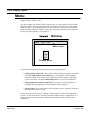
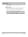
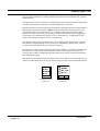
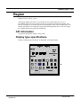
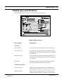
Helpful presentation aids
Other display types and design features that you can use to enhance the presentation of data
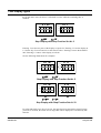
include:
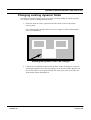
• Layering. This feature lets you create a format that consists of several layers, any
or all of which can be visible at any given time. Once you have created the different
layers, you can let the Sammi user hide and/or show a layer to reduce the
complexity of the format (see next page).
• Paging. This feature lets you connect various formats and pages between them
using the Sammi paging commands (see the discussion on the next page and in
Chapter 4.).
Ñ ÒÓ
Ô
Format
#1
Ñ ÒÓ
Ô
Format
#2
Ñ ÒÓ
ÔÕ
Format
#3
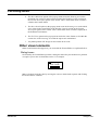
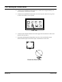
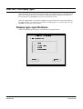
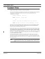
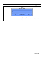
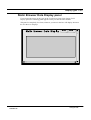
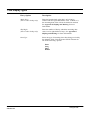
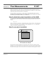
• On-line help. This feature lets you store help information for a format or a
dynamic field in a text file where the Sammi user can view it by clicking the mouse
OPTION button while holding the SHIFT key down (see Chapter 4 for details).
DONE
OVERVIEW DISPLAY
This window provides an overview of the
total system operation. To use this
window, select the feature that you want
to use and click the left mouse button on
• Entry confirmation. This feature can be used with any dynamic field that allows
user entry of new data. A dialog box pops up, allowing the user to confirm the
entry.
As part of the design process, you may want to plan ways in which these aids can be used
to improve the final Sammi interface.
FWDU
ROVSING A/S
UM-114-002-ROV Issue 2.2
User Manual
15 August 1999
2-28 Getting Started
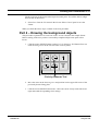
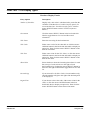
Creating a user-friendly interface
For maximum ease of use, each format that you design for Sammi should present data so
that it is simple to read and visually uncluttered. When you have to present a lot of data,
there are two approaches that you might use:
• Creating multiple formats, each presenting a different category or “level” of data.
The Format Editor lets you create as many different formats as desired to provide a
multiple-window interface. For example, you might start with a single format that
presents a summary overview of the data (see diagram below), then tie other
formats to it that present different levels of detail.
ã ä å æ ä çå è
ë ì í î é ëê ï î ð
û Ö Ö ß ×Þ ØÛ ÙÝ ü
ñ íò ó ô õ ï ö ï ÷
ø ï ù ì í ÷ú
Ú Û Ü Ý Ö× × Ü Þ Ø ß Ù à × á â
û Ö Ö ß ×Þ ØÛ ÙÝ ü
õé ý ôõï ö ï ÷
ø ï ù ì í ÷ú
Ú Û Ü Ý Ö× × Ü Þ Ø ß Ù à × á â
You can use push buttons, paging, or menus to link formats together in such a way that
users can easily and intuitively work their way up, down, or across a series of data
displays. For example, you might have a map of a region with transparent push buttons
over each major city. Clicking on a city calls up another window (or series of windows)
with sales figures, demographics, shipment volumes, or other information for that city.
FWDU
ROVSING A/S
UM-114-002-ROV Issue 2.2
User Manual
15 August 1999
Getting Started 2-29
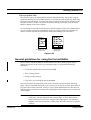
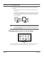
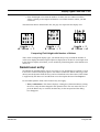
• Creating a single format with several "layers" (up to 64). The Sammi user can then
hide/show each layer with the Layers Attribute panel, which the user accesses
either by clicking the mouse OPTION button in the format and clicking the mouse
SELECT button on the Modify Layers option or by adding the Layer format with
the add-win command in the Runtime Environment.
Layering can be automatic so that when the user zooms (magnifies) a format, the layers
disappear/reappear (declutter/clutter) automatically depending on the level of
magnification. The levels are controlled by you, the format designer, at format creation
time.
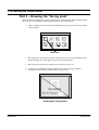
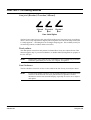
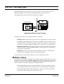
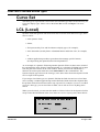
Prototyping/review cycles
Unlike other interface building programs, all designs created with the Format Editor are
immediately usable by the Sammi Runtime Environment. This saves compiling and linking
time. Instead of simply creating a picture of an interface, you use the Format Editor to
create actual, ready-to-use interfaces.
You can still use manual sketches to draft the interface design, if that is what your review/
approval process requires. But the Format Editor also makes it easy to start prototyping
with a working interface and to move the design through multiple review and
demonstration cycles until final approval is reached.
INITIAL
DESIGN AND
TESTING
(Working
Prototype
REVIEW/
SUGGESTED
CHANGES
REDESIGN,
RETESTING
FINAL
WORKING
INTERFACE
Typical Work Flow for Interface Development
You can use the hard-copy command (see the Command Reference) to produce highquality printouts of the final interface design in place of hand-drawn or drafted sketches.
With the FWDU you can quickly check the formats you have designed by previewing
them.The preview sends random data to the displays with-in the limits specified for the End
Item.
Format naming/tracking
You have to comply to the Mission Database naming conventions. You may use letters,
numbers and the underscore character. The names are checked when you create End Items
in the I_MBD. You may consider a standard naming scheme that will help you and others
keep track of the various formats. It is also useful to use Virtual Nodes for grouping formats
and other data types.
FWDU
ROVSING A/S
UM-114-002-ROV Issue 2.2
User Manual
15 August 1999
2-30 Getting Started
Starting the FWDU Format Editor
NOTE:
Before the FWDU can be used for the first time, it must be installed on your
workstation. Please see the FWDU installation guide.
To start editing with the FWDU Format Editor select an End Item of the type
FWDU_SYNOPTIC_DISPLAY, FWDU_LIBRARY_BINARY, or
FWDU_COMPOSITE_BINARY and click with the right button. Now select the Tools and
then FWDU Editor ... The FWDU Format Editor will now start.
NOTE:
If you want to edit an End Item of type FWDU_HELP_TEXT,
FWDU_SYMBOL_TABLE_TEXT,
FWDU_DYNAMIC_OBJECT_TABLE_TEXT, FWDU_LIST_TEXT,
FWDU_CONVERSION_TEXT, FWDU_DATA_DEF_RECORD_TEXT, or
FWDU_EQUIPMENT_CONSTRAINTS_TEXT you need to use the FWDU
Text Editor. See chapter “The FWDU Text Editor” on page 365.
After a brief pause, the Format Editor Control panel appears, as shown below. This panel
has (from top to bottom):
• a main menu,
• push buttons,
• a message line, and
• a command line.
Each item on the main menu has an associated pull-down menu, which may or may not
have an associated “cascading” menu.
All format level commands, most editing commands, and other global commands are
found on these menus. The push buttons are used to draw, edit, and manipulate static
graphical objects in the Drawing Area. The message line displays system prompts,
warnings, and general information. The command line is where you enter any
command that is not available from the menus.
FWDU
ROVSING A/S
UM-114-002-ROV Issue 2.2
User Manual
15 August 1999
Getting Started 2-31
The Format Editor is now started and ready to use. Most Format Editor operations are
discussed later in this chapter under General guidelines for using the Format Editor. But
first let’s take a quick tour of the Format Editor to make sure you understand all of its
components.
A quick tour of the Format Editor
Before you start using the Format Editor, please be sure you understand the features
described on the following pages. If you have already started the Format Editor, you can
practice working with some of these features.
Using the keyboard
The workstation keyboard is used in Sammi to enter commands or data. Since the correct
keystrokes vary from one workstation to the next, we have provided a chart below to help
you determine the correct keystrokes for each possible operation. For example, to tab up
on a Sun workstation, press SHIFT R8 (hold down the SHIFT key and press the R8 key).
To tab down on a DEC, press SHIFT KP2 (hold down the SHIFT key and press the number
2 on the numeric keypad).
Standard Sammi Keystrokes
Function
Sun
Keyboard
Display
command
window
F1
Add a window
F2
Delete a
window
F3
Confirm
F4
Cancel
F5
Page forward
F6
Page back
F7
Page up
F8
Page down
F9
Add window
FWDU
ROVSING A/S
sample_
main
F10
Quit
Sammi
KP1
Confirm
KP2
Cancel
KP3
Erase to
end-of-line
KP4
UM-114-002-ROV Issue 2.2
User Manual
15 August 1999
2-32 Getting Started
Function
Sun
Keyboard
Erase field
KP5
Home
KP7
Cursor up
KP8
Tab up
ShfKP8
Previous
word
KP9
Cursor left
KP10
Tab left
ShfKP10
Cursor
right
R12
Tab right
ShfR12
Insert
mode on/
off
R13
Cursor
down
R14
Tab down
ShfR14
Enter
R15
Backspace
Bksp
Delete
Del
When multiple windows are shown on the same monitor (or on a set of monitors)
simultaneously, any keys that you press will apply only to the window with the focus; that
is, to the window in which the cursor is located. You can change the window focus by
moving the mouse cursor into a window and pressing the mouse SELECT button. The
process that is controlling the active window handles any keyboard input.
NOTE:
All keys are reprogrammable. The keys are programmed using the
keydefs.dat file in the $FWDU_HOME/lib directory. If the keystrokes
shown in the above table do not work, ask your system administrator for help.
The mouse
Many operations in the Format Editor must be performed using a pointing device, such as
a mouse or trackball. Use of the mouse is discussed below.
Mouse movement
You can use the mouse to move the cursor anywhere on the screen. If your workstation has
multiple monitors, rolling the mouse or trackball continuously in one direction moves the
cursor across each of the screens.
FWDU
ROVSING A/S
UM-114-002-ROV Issue 2.2
User Manual
15 August 1999
Getting Started 2-33
Cursor shapes
Normally, the mouse cursor looks like a slanted arrow. As you work with the Format
Editor, however, the cursor may change shape to indicate that a special operation is
underway. Typical cursor shapes are shown below:
Copy
Select
Draw
Create Text
Move
Delete
Typical Cursor Shapes
Mouse buttons
The mouse buttons are used for various standard functions in the Format Editor. To avoid
potential confusion between two- and three-button mice, this manual refers to mouse
buttons by their functions, as shown below:
þÿ ÿ
ÿ
þÿ ÿ
ÿ
Two-Button
Mouse
Three-Button
Mouse
Mouse Button Functions
Button Name
Button Function(s)
SELECT
Used to click on selections and drag window panels or
graphic objects.
Used to move text cursor to new location.
Used to indicate control points when drawing background
objects (see Chapter 5 for details).
FWDU
ROVSING A/S
UM-114-002-ROV Issue 2.2
User Manual
15 August 1999
2-34 Getting Started
OPTION/MENU
Used to pop up menus and/or option lists. Which pop-up
menu or list appears depends on the location of the mouse
cursor:
If the mouse cursor is outside of a DFD, or over a DFD
with no pop-up option list, the pop-up menu defined as
$MAINMENU appears.
If the mouse cursor is over a DFD (non-Motif) with an
assigned pop-up option list (or selection list or menu), that
list appears except during drawing operations that use the
OPTION button to complete. These are drawings of
polylines, polygons, open and closed splines, flip
operations, and moving objects with the Front and Back
operations. Otherwise, when no option list is specified for
this DFD, a pop-up message appears stating "No Menu
Available".
Used to indicate last control point when drawing objects
with more than two control points (as explained in
Chapter 5).
Used with SHIFT key to view on-line “help” information
(hold down SHIFT key before clicking OPTION/MENU).
NOTE:
While in the Format Editor using the SHIFT + OPTION/MENU for help only
displays the standard option menu.
Always use the SELECT button for “clicking” and “dragging” the mouse cursor, unless
otherwise directed. Clicking means to press the button and release it while in one position.
Dragging means to hold down the button while you move the mouse.
FWDU
ROVSING A/S
UM-114-002-ROV Issue 2.2
User Manual
15 August 1999
Getting Started 2-35
The Format Editor Control panel
The Format Editor provides a Control panel that appears when you first start the program.
This panel has several areas:
• The Main Menu for accessing the different commands.
• The Drawing Tools buttons to create static objects for formats. (See Chapter 5.)
• The Snap and Grid buttons for turning those functions on and off. (See Chapter 5.)
• The command line where you enter Sammi commands.
• The area above the command line where error messages, status information, and
command feedback are displayed.
FWDU
ROVSING A/S
UM-114-002-ROV Issue 2.2
User Manual
15 August 1999
2-36 Getting Started
Pull-down menus
The following table is a summary of each of the menus and their options.
Format Editor Control Panel Menus
FWDU
ROVSING A/S
Menu option
Command equivalent
Purpose
File-Open
NA
Edit an existing format.
File-Save
NA
Save the format EI to the
MDB.
File-Save As
NA
Save the format as
another EI in the MDB.
File-Insert File
NA
Insert a format from the
filesystem.
File-Import Fmt
NA
Import an entire format
into the Drawing Area.
File-Import Image
NA
Import an image into the
Drawing Area.
File-Dismiss
NA
Exit current format.
File-Attributes
NA
Display the Format
Attributes panel.
File-Exit
quit
Exit FWDU.
UM-114-002-ROV Issue 2.2
User Manual
15 August 1999
Getting Started 2-37
Format Editor Control Panel Menus
Menu option
Command equivalent
Purpose
Edit-Undo
n/a
Undo last command.
Edit-Resize
n/a
Change size of objects,
including DFDs.
Edit-Move
n/a
Reposition objects, including DFDs.
Edit-Copy
n/a
Copy objects, including
DFDs.
Edit-Static Attrib
n/a
Change the attributes of an
existing static object. Suboptions are:
Color
Line Style
Fill Style
Font
All (all of the above)
FWDU
ROVSING A/S
Edit-DFD Attrib
change-dfd <DFD name>
Edit an existing DFD.
Edit-Layers
n/a
Add the Layers Display
panel
Edit-Preferences
n/a
Add the System Preferences panel for entering
specific global system
parameters.
Edit-Delete
delete-dfd
Erase an existing object
or DFD.
View-Front
n/a
Bring an object to the
front (top) of the format.
View-Back
n/a
Send an object to the back
(bottom) of the format.
View-View DFDs
update-dfd
Show how DFDs will look
in Sammi.
View-Preview
n/a
Preview current format.
View-Redisplay
n/a
Redraw all objects in the
Drawing Area.
Composites Read Composite
read-format -p
Read a grouped set of
objects from MDB.
Composites Save Composite
write-part
Save a grouped set of
objects to MDB.
UM-114-002-ROV Issue 2.2
User Manual
15 August 1999
2-38 Getting Started
Menu option
Command equivalent
Purpose
Dynamic Fields
Display Palette
add-window
$fb-dfdpal
Show the DFD Palette.
n/a
Read a DFD from the
MDB in to current format.
n/a
Save the dynamic field
into the MDB.
Add DFD
add-dfd
Create a new DFD.
Style-Font
n/a
Add the Current Font
Selection panel.
Style-Colors...
n/a
Add a panel for selecting a
color, either:
Dynamic Fields
Read DFD Lib
Dynamic Fields
Save DFD Lib
Dynamic Fields
Select... Adds the Color
Selection Display panel.
Palette... Adds the Color
Palette panel.
FWDU
ROVSING A/S
Style-Line Style
n/a
Add the Current Line
Style panel.
Style-Fill Style
n/a
Add the Current Fill Style
panel.
Style-Snap/Grid
n/a
Add the Current Spacing
panel.
Style-Constraints
n/a
Add the Line Constraints
panel.
Style-Recolor
n/a
Displays the Recolor
Style panel.
Help
n/a
Add a help window.
UM-114-002-ROV Issue 2.2
User Manual
15 August 1999
Getting Started 2-39
The Drawing Area ($fb-bkgd)
The Drawing Area ($fb-bkgd) is the “blank canvas” on which you can draw static
objects and dynamic fields for new formats. Formats to be changed also appear here for
modification.
The size of the Drawing Area and the positioning of elements within it correspond exactly
to the size and layout of the final Sammi window as displayed in the Runtime Environment.
When a format first displays in the Format Editor Drawing Area, it is at its maximum size
as defined in the Maximum Width and Maximum Height fields on the Format Description
panel. The default Maximum Width is 610 (pixels) and Maximum Height is 400 (pixels).
When you zoom in on the format, scrollbars appear on the Drawing Area.
Moving panels
To move a panel to a different position, follow these steps:
1. Move the cursor to the name printed in the window manager title bar at the top of
the panel.
2. Hold down the mouse SELECT button.
3. Drag the mouse in the direction you want the panel moved. As you move the
mouse, an outline of the panel moves across the screen.
4. Release the mouse SELECT button when the outline reaches the desired location.
The panel reappears at the new location.
NOTE:
Some workstation window managers have a pop-up menu which you access by
clicking the mouse OPTION button on either the border or on a button in the
upper left corner of a window to move panels. Others may not show a
moving outline. Some let you drag any part of the window border. If the above
method does not work, please see your window manager manual, or ask your
system administrator for instructions.
To change the overlap of a partially obscured panel, click the mouse cursor along the edge
of its frame. The obscured panel pops to the front.
NOTE:
On some workstations, you must use a pop-up menu to change the overlap. If
the above method does not work, please see your workstation manual or
window management system documentation for instructions.
Zooming the Drawing Area
When the Drawing Area is displayed, you may want to view it in a magnified (zoomed)
FWDU
ROVSING A/S
UM-114-002-ROV Issue 2.2
User Manual
15 August 1999
2-40 Getting Started
state. You can do this in one of two ways. The first is by a menu that pops up when you
click the mouse OPTION button in the Drawing Area outside of a dynamic field. This
menu contains the following options:
Undo
Undoes the last operation.
Redisplay
Redraws the visible format.
Zoom In
Magnifies (zooms) the Drawing Area to
twice its previously-displayed size. The
center of the Drawing Area becomes the
center of the zoomed area.
Zoom Out
Reduces (demagnifies) the Drawing Area
to half its previously-displayed size. The
center of the previous display is the center
of the new display.
Zoom Box
Lets you use a box outline to select an
area to zoom on the current display with a
box outline. Once you draw the box, the
area inside of it is scaled and panned, so
that the contents of the box fill the Drawing Area.
To draw the box, click the mouse
SELECT button in the Drawing Area
where you want the upper-left corner of
the box to start, move the cursor down
and to the right until the box encompasses
the area that you want to zoom, and click
the mouse SELECT button again.
Full View
Rescales the format so that the entire format fits in the Drawing Area.
Reset Initial
Rescales the format to its initial size.
Reset Maximum
Rescales the Drawing Area to its maximum size.
Pan To
Lets you select the center point for panning.
Remove All
Removes everything on the active layer.
The second way to zoom the Drawing Area is:
1. In the Format Editor Control panel command line, enter the command:
add-window zoom
2. When the Zoom Format window appears, move it to an unused area of your
display using the procedure described earlier in the section Moving panels.
3. Enter $fb-bkgd in the Format Name field of the Zoom Format window.
The Zoompad on the Zoom Format window resizes to the size of the Drawing Area.
FWDU
ROVSING A/S
UM-114-002-ROV Issue 2.2
User Manual
15 August 1999
Getting Started 2-41
4. Click the mouse SELECT button on one of the ratio buttons to the left of the
Zoompad to magnify or demagnify the Drawing Area. The ratio buttons are
cumulative; that is, if you press the 2:1 button twice, you have effectively
magnified the Drawing Area to 4 to 1. The ratio buttons are:
2:1
Magnify the outlined area of the format
by two times.
4:1
Magnify the outlined area of the format
by four times.
8:1
Magnify the outlined area of the format
by eight times.
1:2
Shrink the outlined area of the format to
half its current size.
1:4
Shrink the outlined area of the format to
one fourth it current size.
1:8
Shrink the outlined area of the format to
one eighth its current size.
Full
Return the format to its regular size (1:1).
Notes on panning and zooming
You should be aware of the following issues in panning and zooming:
1. To change either the maximum or the initial size of a format, change the initial
and maximum fields in the Windows Control section of the Format Description
panel. This is accessed by choosing the option "Attributes" under "File" on
$fb-cmd window. (See Chapter 4 for information on these fields.) If you resize the
format using the window manager and add objects to the area outside the maximum size, your changes will not be visible unless you increase the maximum
fields under height and width of the Window Control section on the
Format Description panel.
NOTE:
If you use the area outside the maximum size, you are creating "invisible"
objects and DFDs that can cause problems at runtime.
2. The grid is drawn only to the maximum size of the format, even if you Zoom Out
on the format. This means that sometimes you will not have a grid on the bottom,
top, and/or sides of the Drawing Area.
3. If you zoom, pan, and resize the Drawing Area several times (especially if the
aspect ratio is substantially distorted), the cursor coordinates shown in the
message line of the Format Editor Control panel may stop updating because the
cursor is beyond the limits of the maximum size of the format. (See Note 1 above
on increasing the maximum size.)
FWDU
ROVSING A/S
UM-114-002-ROV Issue 2.2
User Manual
15 August 1999
2-42 Getting Started
4. The Reset Maximum option of the pop-up menu resets the Drawing Area to the
maximum size (values in the maximum fields of the Window Control section on
the Format Description panel) of the format. This is the default when a format is
edited in the Format Editor.
5. The Reset Initial option on the pop-up menu resets the Drawing Area to the initial
size (values in the initial fields of the Window Control section on the Format
Description panel) of the format. This is the default when a format is displayed in
the Runtime Environment.
6. The Full View option on the pop-up menu scales the entire format to fit within the
current size of the Drawing Area with the aspect ratio maintained.
7. Any bitmap and/or GIF images on the format do not scale.
Other visual elements
Other visual elements that appear as you work with the Format Editor are explained below.
Dialog boxes
Occasionally, the Format Editor presents a dialog box that calls your attention to a problem
or requires you to take an immediate action. For example:
Make selections in a dialog box by moving the cursor to the desired response and clicking
the mouse SELECT button.
FWDU
ROVSING A/S
UM-114-002-ROV Issue 2.2
User Manual
15 August 1999
Getting Started 2-43
Pop-up option lists
In some cases where the Format Editor requires information entry, it provides a pop-up
option list showing all your available choices. To view the list, click on the entry field using
the mouse OPTION button. To select from the list, click the mouse SELECT button on the
desired selection; to remove the option list without making a selection, click the mouse
SELECT button on the Cancel button.
You must make a selection or click the mouse SELECT button on the Cancel button before
you can continue using the Format Editor. Some pop-up lists include an OK button on
which you must click the mouse SELECT button after making your selection(s).
page_up
page_down
page_forward
page_back
page_up
page_down
page_forward
page_back
Cancel
Scrollable List Box
Scrollable
Option
List
Option List
Cancel
OK
Radio Box
List Box
Option
List
Option List
Option List
General guidelines for using the Format Editor
Once you have started the FWDU (Format Editor) from the I_MDB with the panels
displayed correctly on the screen, you can begin using it to perform the following
operations:
• Create new formats and save them in the MDB.
• View existing formats.
• Change existing formats.
• Copy (Save As) existing formats to the MDB.
General procedures for performing each of these functions are listed on the following
pages. Keep in mind that during any work session you can use any of these procedures in
any order and as often as desired, as long as your system administrator has provided you
with the proper permissions. Procedures for quitting the Format Editor are given at the end
of this chapter.
NOTE:
FWDU
ROVSING A/S
The procedures in this section are intended as general guidelines. Since the
actual steps you take depend on the format design, we have omitted some
details and referred you to later chapters where appropriate. The lessons in
Chapter 3 will also repeat many of these steps, but in the context of a specific
example.
UM-114-002-ROV Issue 2.2
User Manual
15 August 1999
2-44 Getting Started
Creating new formats
Use the following steps each time you want to create a format. You can create any number
of separate formats desired during a given work session.
NOTE:
Before editing a format one and only one Equipment Constraint End Item has
to be created. See “The FWDU Text Editor” on page 365.
1. In the I_MDB create an End Item(EI) of type FWDU_SYNOPTIC_DISPLAY.
2. From the I_MDB invoke the newly created EI by selecting the EI and right clicking on it. Then select Tools and then FWDU Editor ...
3. First time the Format Description panel appears. Change the values on the panel
as you wish. (See Chapter 4 for details on this panel.)
4. Use the Drawing Tools buttons to draw all background objects in the format (as
explained in Chapter 3 and Chapter 5).
5. Save you work.
Creating dynamic fields (DFDs) with the Icon Palette
Generally, to create dynamic fields:
1.
Select the Display Palette option from the Dynamic Fields menu on the Format
Editor Control panel. The DFD Palette panel displays.
"
!
#
$
%
&
'
n
o
p
)
q
u
*
r
u
v
u
(
+
,
"
s
v
u
t
w
v
x
v
w
x
-
#
$
#
"
-
.
/
0
6
1
2
3
3
4
5
7
)
1
!
#
:
!
4
0
8
k
'
l
(
m
;
#
(
9
"
<
=
>
?
@
=
>
A
"
-
?
S
$
R
E
>
?
F
A
@
=
>
A
"
[
D
H
7
B
G
D
C
D
L
J
7
6
H
J
7
6
3
3
/
7
9
0
J
/
I
I
3
/
M
J
3
3
M
I
4
7
6
/
M
2
0
0
/
K
3
3
/
K
¤
¤
¤
¤
¤
¤
¤
¤
¤
¤
¤
¤
¤
¤
¤
¤
¤
¤
¤
¤
¤
¤
¤
¤
¤
¤
¤
¤
¤
¤
¤
¤
¤
¤
¤
¤
¤
¤
¤
¤
¤
¤
¤
¤
¤
¤
¤
¤
¤
¤
¤
¤
O
P
Q
P
R
S
¤
¤
N
R
T
:
-
T
U
V
W
X
Y
Z
V
¡
¢
£
¢
H
y
$
T
"
[
.
8
\
]
9
2
I
4
}
1
4
3
4
0
^
_
`
a
^
b
d
g
a
f
}
a
h
e
e
h
c
a
e
g
z
{
e
|
~
|
d
a
f
6
J
H
i
2
J
1
8
9
j
/
i
1
/
4
9
4
I
J
/
j
J
5
9
6
3
J
3
8
3
2
I
4
3
4
\
3
3
2
I
9
/
4
2. Select the type of dynamic field you want to add from the scrollable panel of icons
by clicking the mouse SELECT button on an icon.
FWDU
ROVSING A/S
UM-114-002-ROV Issue 2.2
User Manual
15 August 1999
Getting Started 2-45
3. Move the cursor into the Drawing Area. The cursor changes to an icon of the
selected DFD with a bounding box for the DFD attached only if it is selected from
the DFD Palette panel.
4. Position the cursor in the desired location and click the mouse SELECT
button. The DFD Display panel for the selected dynamic field appears with preset
values.
5. Make any changes on the DFD Display panel that you want.
6. Save each dynamic field by clicking on the Save DFD button at the bottom of the
DFD Display panel.
NOTE:
You can continue creating DFDs of the same type by skipping step 2 above.
The DFD icon that you selected remains selected until you click the mouse
SELECT button on it again or click on another icon.
7. Repeat steps 2, 3, 4, and 5 for each dynamic field created.
8. To end the above process and remove the DFD Display panel, click on the
Cancel DFD button on the bottom of the DFD Display panel to close all the
panels.
9. To see a static view of the DFDs, select the View DFDs option from the View
menu.
10. To see an animated preview of the DFDs as they will appear in the Run Time Environment, select the Preview option from the View menu.
Creating dynamic fields (DFDs) with the Add DFD option
Another way to create a DFD is to:
1. Select the Add DFD option from the Dynamic Fields menu.
2. Move the cursor into the Drawing Area to display the DFD Display panel. Use the
mouse SELECT button to position and draw the desired size DFD.
3. In the DFD Display panel, click the mouse OPTION button in the box beside
Display Type to display a list of DFD types. Select the DFD type by clicking the
mouse SELECT button on the name in the list.
FWDU
ROVSING A/S
UM-114-002-ROV Issue 2.2
User Manual
15 August 1999
2-46 Getting Started
To create a duplicate DFD from one that exists:
1. Retrieve the DFD using the DFD Attrib option on the Edit menu. This loads the
DFD Display panel with the DFD information.
2. Now repeat steps 1 and 2 on creating dynamic fields. The DFD Display panel
appears with the information from the original DFD.
Saving and testing a format
Once you have created a format with its dynamic fields, you must save and test it.
1. To save the completed format in the MDB, select the Save or Save As... option
from the File menu on the Format Editor Control panel. The Save As... option allows you to save the to format an existing display end item and automatically
clears the format from the Drawing Area. The Save As pops up the following
window.
2. Type the Pathname that you want to save to. You can also use Pathname Support
(PNS) instead. PNS is an interactive browser where all valid End Items can be
seen and selected. Note that only End Items of valid type are shown in the PNS.
NOTE:
You can use Preview in the View menu to test and animate your format dynamically.
Viewing or changing existing formats
The previous discussion covered creating a new format. The following steps can be used
each time you want to view or modify an existing format. This procedure works whether
you have just started the Format Editor or have already used it to create or modify other
formats. Remember that this is a general procedure, with references to specific details in
later chapters.
1. Select the Open option from the File menu on the Format Editor Control panel.
An Open_popup window appears (similar to the SaveAs_popup).
2. Write the Pathname to an End Item of type FWDU_SYNOPTIC_DISPLAY or
use Pathname Support for a scrollable list of the existing synoptic display.
3. Click on the OK button.
The format appears in the Drawing Area.
FWDU
ROVSING A/S
UM-114-002-ROV Issue 2.2
User Manual
15 August 1999
Getting Started 2-47
Viewing and modifying the Format Description panel
To view the Format Description panel:
1. Select the Attributes option from the File menu on the Format Editor Control
panel. The Format Description panel appears.
2. Make any desired changes on the Format Description panel (see Chapter 4 for
more details).
3. Click the mouse SELECT button on the OK button.
Inserting UNIX files into the MDB
To insert a format created with the standard SAMMI into an MDB End Item of type
FWDU_SYNOPTIC_DISPLAY, use the Insert File in the File menu. The following
window appears:
1. Path: Write the Pathname to the End Item you want the format to be insert in.
You can also use the Pathname Support.
2. File: Write the complete filesystem path to the file you want to insert.
3. Click the mouse SELECT button on the OK button.
Modifying static background objects
To modify static background objects:
Use the Drawing Tools buttons on the Format Editor Control panel to change static
background objects as desired. Most objects are changed by clicking on the appropriate
tool button, then clicking the locations in the Drawing Area where changes are required
(see Chapter 5 for more details).
Modifying dynamic fields (DFDs)
To view or modify dynamic fields:
1. Select the DFD Attrib option from the Edit menu on the Format Editor Control
panel.
FWDU
ROVSING A/S
UM-114-002-ROV Issue 2.2
User Manual
15 August 1999
2-48 Getting Started
2. In the Drawing Area, move the cursor to the outline of the dynamic field (DFD)
that you want to examine or modify and click on it with the mouse SELECT
button. The description panels for that DFD appear.
3. After making desired modifications to any of the description panels for the
dynamic field, click on the Save DFD button at the bottom of the DFD Display
panel. Clicking on the Cancel DFD button will quit dynamic field editing without
any modification to the DFD.
4. Repeat steps 2 and 3 for each dynamic field to be modified.
5. Finish dynamic field editing by clicking on the Cancel DFD button at the bottom
of the DFD Display panel.
FWDU
ROVSING A/S
UM-114-002-ROV Issue 2.2
User Manual
15 August 1999
Getting Started 2-49
Other format editing operations
While editing a format, you can perform several editing operations.
Moving static objects
To move a static object or dynamic field:
1. Click the mouse SELECT button on the Move Tool button, or select the Move
option from the Edit menu on the Format Editor Control panel.
2. Move the cursor to the Drawing Area and click the mouse SELECT button on the
object to be moved.
3. Move the outline of the object to the location where you want it located, and click
the mouse SELECT button again.
Deleting static objects
To delete a static object or a dynamic field:
1. Click the mouse SELECT button on the Eraser Tool button, or select the Delete
option from the Edit menu on the Format Editor Control panel.
2. Move the cursor to the Drawing Area and click the mouse SELECT button on the
object to be deleted. It disappears from the screen.
NOTE:
If you make a mistake, immediately select the Undo option on the Edit menu,
or click the mouse OPTION button and select the undo option from the
resulting list.
Adding static objects and dynamic fields (DFDs)
Use the Drawing Tools buttons to draw all static background objects in the format. Most
drawing is done by clicking a Drawing Tool button, then clicking at the desired location in
the Drawing Area (as described in Chapters 3 and 5).
To add new dynamic fields (DFDs), see the section Chapter 2 General guidelines for using
the Format Editor.
Viewing dynamic fields (DFDs)
If you would like a static view of your dynamic fields to see how they appear, select the
View DFDs option from the View menu.
If you would like an animated preview of your display to see how they appear, select the
Preview option from the View menu.
NOTE:
FWDU
ROVSING A/S
Random values derived from the End Items’ definition in the MDB are sent to
the dynamic fields so they appear animated.
UM-114-002-ROV Issue 2.2
User Manual
15 August 1999
2-50 Getting Started
Copying formats
To create a new format very similar to an existing format, copy the existing format, then
modify the copy and save it as a new format. Follow these steps:
1. Open the synoptic display (format) you want to copy.
2. Make any changes desired before saving.
3. Use the Save As...functionallity from the File menu on the Format Editor
Control Panel to save the synoptic display in another End Item. You may select
an new created FWDU_SYNOPTIC_DISPLAY type End Item or an already existing End Item of same type.
Deleting formats
Use the I_MDB to delete FWDU_SYNOPTIC_DISPLAY’s.
Quitting the Format Editor
To exit the Format Editor completely:
1. If you have been creating or editing a format and want to save your changes,
select the Save option from the File menu on the Format Editor Control panel.
2. Select the Dismiss option from the File menu on the Format Editor Control panel.
The Drawing Area goes blank.
3. In the command line on the Format Editor Control panel, type:
quit <RETURN>
or
select the Exit option from the File menu of the Format Editor Control panel. The
following dialog box appears:
4. Click the mouse SELECT button on Yes.
FWDU
ROVSING A/S
UM-114-002-ROV Issue 2.2
User Manual
15 August 1999
CHAPTER 3
Learning the Format Editor
3-51
Once you understand the Format Editor’s basic functions described in the first two chapters,
you are ready to practice with working examples. This chapter teaches you how to build a
sample format in a series of self-paced lessons. The lessons should be completed in the
order presented, without skipping, since each involves components created in previous
lessons.
Each lesson is designed to be completed in one session; therefore, do not start a lesson
unless you intend to complete it. However, you may quit after any particular lesson and
later resume with the next lesson.
Each of the Format Editor display panels discussed in this chapter is like a standard window
that can be moved, resized, or overlapped on most platforms. The following lessons assume
you are using a window management system that allows you to manipulate windows
dynamically by simple mouse movements such as clicking and dragging.
If you are not using such a window manager, please consult your window system operating
manual or System Administrator for correct instructions on moving, resizing, and
overlapping windows.
NOTE:
FWDU
ROVSING A/S
If you must stop in the middle of a lesson, save your work by selecting Save
from the File menu on the Format Editor Control panel.
UM-114-002-ROV Issue 2.2
User Manual
15 August 1999
3-52 Learning the Format Editor
About the sample format
All the lessons in this chapter involve the steps for constructing the sample format shown
below:
¨
¥
¥
¦
§
°
testformat:
¥
©
ª
«
¬
²
Temperature Control
¥
¦
«
®
¦
ª
¬
¥
¯
ª
¦
©
±
ª
©
The Sample Format
External look and operation
The sample format is designed to look like a control panel, with a data field and a simulated
meter. To heighten the illusion of a control panel, we have included a solid border around
the panel and “screws” to hold the panel in place. The Sammi user can use the control panel
to:
• Enter a new temperature.
• See Sammi display the new temperature on the meter.
Naturally, the format does not perform these functions while you are creating it in the
Format Editor. You must run the Runtime Environment to test the format. Therefore, the
training modules in this chapter teach you not only how to create background objects and
data-driven dynamic fields using the Format Editor, but also how to test them in the
Runtime Environment.
Internal mechanisms
The external mechanisms listed above are only part of the story. Inside the Runtime
Environment are many internal mechanisms working to produce the effects seen on the
screen.
FWDU
ROVSING A/S
UM-114-002-ROV Issue 2.2
User Manual
15 August 1999
Learning the Format Editor 3-53
You must understand these internal mechanisms before you can create truly useful and
workable formats.
¼
Contributed Software
FWDU_SERVER
Data Server
(s2_ndbmsvr)
»
´
testformat:
³
µ
Temperature Control
µ
³
³
»
»
»
½
¼
Database
(ndbmtest1)
MCD/DMS
¶
·
¶
¾
¿
¾
¾
À
¿
¿
Á
À
À
¾
Á
Á
Â
¾
¾
Ã
Â
Â
Ä
Ñ
Í
Å
Í
Ã
¶
Æ
Î
Í
Ç
Ñ
Ç
È
Ñ
Ç
È
È
É
Ê
Ë
Ä
Í
Ê
Ï
Ì
Ê
Á
Ë
Ð
Ì
Ê
Network
¹
¸
º
How the Sample Format Works
The two dynamic fields on the testformat format are created using the Real and Meter
display types. For test purposes, both dynamic fields work by accessing the same record
element in an MDB. In Run Time Environment the FWDU_SERVER is actually called
MCD and this accesses data in the DMS (see illustration above).
The meter accesses the record element in the DMS via the MCD, it reflects new values as
soon as its dynamic field is refreshed by the MCD.
The SAMMI concept with various data servers and databases has been replaced with one
data server: FWDU_SERVER. The servername is hidden because there only is the one.
Attributes of measurement End Items are sent to the FWDU_SERVER which will send data
accordingly.
FWDU
ROVSING A/S
UM-114-002-ROV Issue 2.2
User Manual
15 August 1999
3-54 Learning the Format Editor
What you will learn
The lessons in this chapter will lead you step-by-step through a number of procedures that
teach the following elements of the Format Editor and the Runtime Environment:
Lesson 1 – Building a format
Part 1 – Starting the FWDU Format Editor
Part 2 – Setting colors and fonts and adding text labels
Part 3 – Changing the font style
Part 4 – Creating a Real Dynamic Field Definition (DFD)
Part 5 – Creating a Meter Dynamic Field Definition (DFD)
Lesson 2 – Using Sammi to test the format
Part 1 – Testing the format
Part 2 – Changing the format and retesting
Lesson 3 – Modifying the format
Part 1 – Changing the format
Part 2 – Setting up default drawing styles
Part 3 – Drawing a border
Part 4 – Drawing background objects
Part 5 – Completing the background
Though this list does not include everything you can possibly learn about the Format Editor
and the Runtime Environment, it does provide a comprehensive overview of most of the
main features. By following these lessons, you learn quickly how to make a format work in
the Runtime Environment.
FWDU
ROVSING A/S
UM-114-002-ROV Issue 2.2
User Manual
15 August 1999
Learning the Format Editor 3-55
Lesson 1 – Building a format
In the following session, you start the Format Editor and create a format with the basic
display elements.
Part 1 – Starting the FWDU Format Editor
1. To start the FWDU invoke a FWDU_SYNOPTIC_DISPLAY End Item from the
I_MDB.
If the FWDU is properly installed on your system, the Format Editor Control panel
displays:
FWDU
ROVSING A/S
UM-114-002-ROV Issue 2.2
User Manual
15 August 1999
3-56 Learning the Format Editor
Creating a format
To create a new format:
1. If the invoked FWDU_SYNOPTIC_DISPLAY End Item already has been opened
the following Drawing Area panel appears. The header holds the name of the
FWDU Format Editor specific window $fb-bkgd and the SID and the End Item
name.
2. If the invoked FWDU_SYNOPTIC_DISPLAY End Item never has been opened
the window on the next page appears.
FWDU
ROVSING A/S
UM-114-002-ROV Issue 2.2
User Manual
15 August 1999
Learning the Format Editor 3-57
l
Entering data in the Format Description pane
NOTE:
FWDU
ROVSING A/S
Most of the parameters on the Format Description panel have default values
entered. Although most of these are satisfactory for this tutorial, you can
change some of their values. For a more detailed discussion of this panel, see
Chapter 6.
UM-114-002-ROV Issue 2.2
User Manual
15 August 1999
3-58 Learning the Format Editor
To describe the format:
1. Enter the following next to Description in the Format Description panel:
Temperature Control
This description is displayed in the title bar of the format when you run it in the Sammi
Runtime Environment.
2. Click the mouse OPTION button on the box to the right of Color
under Window Background to view a list of background colors.
3. Click in the scroll bar track with the mouse SELECT button until you see the
lightsteelblue label, then click on it with the mouse SELECT button.
4. Adjust the width and height of the format by entering initial and maximum values
for each. The default size of a format is 610 pixels wide and 400 pixels high.
These values are changed when you adjust the size of the Drawing Area in step 2
of the previous section, Creating a format.
— Under the word Width in the Window Control section of the Format
Description panel, enter in the box beside maximum the value that is displayed
in the box beside initial.
— Under the word Height in the Window Control section of the Format
Description panel, enter in the box beside initial the value that is displayed in
the box beside maximum.
NOTE:
In the Equipment Constraints a maximum for the Width and Height is set. For
more details see “The FWDU Text Editor” on page 365.
5. Click the mouse SELECT button on
6.
the OK button at the bottom of the Format Description panel. Notice that the
Drawing Area background color changes to lightsteelblue (as you selected in step
3).
7. Select Save from the File menu in the Format Editor Control panel to save the
format in the End Item you invoked. You can also use Save As to store the format
in a different End Item.
When you finish the above steps, proceed to the next lesson.
FWDU
ROVSING A/S
UM-114-002-ROV Issue 2.2
User Manual
15 August 1999
Learning the Format Editor 3-59
Part 2 – Setting colors and adding text labels
This procedure shows you how to add the first text labels to your drawing. You are only
adding two labels at this point; the rest will be added in later lessons. This procedure also
explains how to use the color palette to set the foreground color before creating an object
and how to “recolor” object attributes. Before starting, make sure you have successfully
completed Part 1 of this tutorial.
Setting default colors
To set the default colors:
1. Choose the Select... option from the pull-right menu that appears when you select
Colors from the Style menu on the Format Editor Control panel to display the
Color Selection Display panel:
Ú
Û
Ü
Ý
Þ
Ü
Û
ß
à
á
â
ã
ä
å
æ
Þ
Ü
Û
ß
à
á
â
ç
è
à
á
è
è
ë
î
ê
Ý
ì
å
æ
Þ
í
ë
ê
Ý
Ý
ß
í
ä
å
ì
å
ì
Ý
í
æ
í
æ
í
è
è
å
â
í
ä
ì
ä
ë
ë
æ
é
ì
é
ë
ä
é
Û
ê
Ý
í
é
è
é
ê
Ý
ë
ê
Ý
Ü
Ü
Ü
Ý
Ý
Ý
á
á
á
Þ
Þ
Ü
Ý
Ý
Ü
Ý
Ý
Þ
Ü
ì
í
Ý
Ý
ß
ß
ì
ß
ì
à
à
à
Ý
Ý
í
Ý
å
ï
ä
à
í
å
ï
ä
à
ë
ë
å
ï
ä
à
ä
ä
Þ
Ý
à
Þ
Ý
à
ä
ä
ð
ð
ë
ä
Þ
Ý
à
ä
ð
Ò
Ó
Ô
Õ
Ö
×
Ø
Ù
2. Click the mouse SELECT button in the scrollbar through under Foreground until
steelblue appears. Click the mouse SELECT button on steelblue. The patch of color
beside the word Foreground changes to steel blue.
3. Click the mouse SELECT button in the scrollbar trough under Background until
midnightblue appears. Click the mouse SELECT button on midnightblue. The
patch of color beside the word “Background” changes to midnight blue.
4. Click the mouse SELECT button on the OK button to change the current
foreground, background, and/or window color, and to close the Color Selection
Display panel.
5. Cancel will close the Color Selection Display panel and not change any colors.
FWDU
ROVSING A/S
UM-114-002-ROV Issue 2.2
User Manual
15 August 1999
3-60 Learning the Format Editor
Setting the fill pattern
To set the default fill pattern:
1. Select Fill Style from the Style menu on the Format Editor Control panel to
display the Current Fill Style panel:
ñ
ò
ó
ó
ô
õ
ö
÷
ø
ù
ù
ú
ö
û
ù
ô
ü
þ
ÿ
ý
2. Click the mouse SELECT button on the No Fill button (the two blank overlapping
squares at the far left under Fill Style). Drawn objects will not hide background
objects with this option selected.
3. Click the mouse SELECT button on the OK button to close the Current Fill Style
panel.
Adding text
To add text to the format:
1. Click the mouse SELECT button on the Text Tool (T) button under Drawing Tools
on the Format Editor Control panel.
2. Move the cursor into the Drawing Area. The cursor changes to a pencil shape.
3. Click the mouse SELECT button in the Drawing Area just below the center.
4. Enter the following:
Current Temperature
and press the RETURN key.
5. Move the cursor below these words in the Drawing Area.
FWDU
ROVSING A/S
UM-114-002-ROV Issue 2.2
User Manual
15 August 1999
Learning the Format Editor 3-61
6. Enter the following:
Enter New Temperature:
and press the RETURN key.
NOTE:
If the words you type do not appear, you may have set the foreground
and background colors the same, you may have set the Fill pattern incorrectly, you may have chosen the wrong tool, or you are not clicking
or pressing RETURN correctly.
7. Select Save from the File menu on the Format Editor Control panel to save
the format.
When you finish the above steps, proceed to the next lesson.
FWDU
ROVSING A/S
UM-114-002-ROV Issue 2.2
User Manual
15 August 1999
3-62 Learning the Format Editor
Part 3 – Changing the font style
To change the font of the text you entered in the last part of this lesson:
1. Select Font from the Style menu on the Format Editor Control panel to display the
Current Font Selection panel.
.
/
0
1
!
"
#
$
%
!
2
=
>
?
@
A
8
.
/
0
1
3
4
5
0
4
7
0
4
7
0
4
<
&
6
;
2
2
0
6
B
8
9
:
'
2
(
)
*
+
,
-
2. When the list of fonts appears scroll through the list to find the entry for “courier
bold 18pt.”
3. Click the mouse SELECT button on this entry.
4. Click the mouse SELECT button on the OK button to close the Current Font
Selection panel.
5. Click the mouse SELECT button on the Recolor Tool button on the top row, far
right under Drawing Tools of the Format Editor Control panel. This sets the
recoloring function by which you can change the color or appearance of drawn
objects or the font of text.
C
D
E
F
G
F
H
The Recolor Tool
FWDU
ROVSING A/S
UM-114-002-ROV Issue 2.2
User Manual
15 August 1999
Learning the Format Editor 3-63
6. Move the cursor into the Drawing Area. The cursor changes to a cross.
7. Click on the two text strings you just created inside the Drawing Area. Each one
should change to the new font.
NOTE:
If you have made errors, click the mouse SELECT button on the Eraser Tool
(immediately to the left of the Recolor Tool), then move the cursor to the
Drawing Area, and click the mouse SELECT button on any object (or text)
you want to erase.
8. Select Save from the File menu on the Format Editor Control panel to save the
format.
Part 4 – Creating a Real
Dynamic Field Definition (DFD)
This procedure lets you add the first dynamic field to the testformat format. This
discussion is broken into several subsets to cover the three different panels that you must
complete. Before starting, make sure you have successfully completed all previous parts of
this lesson. (You should have the testformat format displayed.)
1. Select Add DFD from the Dynamic Fields menu in the Format Editor Control
panel.
2. In the Drawing Area, click the mouse SELECT button to the right of the text string
“Enter New Temperature:”
3. Move the mouse toward the lower right. As you do so, notice the borders of the
dynamic field now appear as an expanding box, and the DFD Display panel
appears.
4. While expanding the box, also notice the values beside Width and Height on the
DFD Display panel are changing. When the value in the box to the right of Width
shows 4 characters (Chr) and the value in the box to the right of Height shows 1
character (Chr), click the mouse SELECT button again. If you cannot get them
adjusted with the mouse, enter them manually (see next section).
FWDU
ROVSING A/S
UM-114-002-ROV Issue 2.2
User Manual
15 August 1999
3-64 Learning the Format Editor
Entering data on the DFD Display panel
To enter data on the DFD Display panel:
1. Click to the right of DFD Name and enter the name inputemp. (Do not press the
RETURN key.)
2. Either press the TAB key or click the mouse OPTION button in the box to the right
of Display Type and select Real from the resulting option list. The Real Display
panel appears. Stay on the DFD Display panel.
3. Click the mouse OPTION button in the box to the right of Data Access Type and
select Universal from the resulting option list. The Data Access Description panel
appears. Stay on the DFD Display panel.
4. Enter 5 in the box to the right of Refresh Rate. This sets the amount of time that
will elapse before the data redisplays (in this case, 5 seconds).
5. Click the mouse SELECT button in the boxes to the right of Enterable and Confirm
FWDU
ROVSING A/S
UM-114-002-ROV Issue 2.2
User Manual
15 August 1999
Learning the Format Editor 3-65
Entry to toggle both to Yes. This allows users to enter data and verify the entry.
6. In the box to the right of Font, click the mouse OPTION button and select “courierbold 18pt.,” then click the mouse SELECT button to set the font for the Real DFD.
WARNING:
Do NOT click on the Save DFD or Cancel DFD button yet.
The Real Display Panel
Now move the cursor to the Real Display panel:
Observe the lightblue color of the Maximum and Minimum value fields. In the FWDU this
means that the values are read-only.The values are taken from the attached End Item. Also
the Data Type is taken from the attached End Item. because the FWDU can read
information about End Items from the MDB several values can be filled automatically.
This also means that the values can not be changed using the FWDU. You will have to use
the I_MDB to change these values. For more details on the Real Display see “Real” on
page 351.
WARNING:
FWDU
ROVSING A/S
Do NOT click on the Save DFD or Cancel DFD button yet.
UM-114-002-ROV Issue 2.2
User Manual
15 August 1999
3-66 Learning the Format Editor
Attaching MDB End Items as Data Sources
NOTE:
In the FWDU the Data Access Description Panel sets up a communication link
between FWDU_SERVER (started automatically at preview) and the SAMMI
Runtime Environment. This is done implicitly without need for user interaction. This can be done because the end data server is known and well defined.
Now move the cursor to the Data Access Description panel:
The FWDU does not use read keys nor write keys. Instead it uses a read-only field, Data
Access End Item, to record attachment of MDB measurement End Items:
1. Press the End Item button. The following window appears:
2. The MDB Pathname is prefixed with a best guess (Current CCU/CDU).
Complete the Pathname (a measurement End Item). As a help you could use
Pathname Support instead.
3. Press OK button. As a result the Data Access End Item field is filled with the
specified End Item.
When attaching an End Item the existence of the End Item is verified. Only End Items in
the current scope (CCU/CDU) can be attached. If the End Item is found the type of the End
FWDU
ROVSING A/S
UM-114-002-ROV Issue 2.2
User Manual
15 August 1999
Learning the Format Editor 3-67
Item - which is found automatically in the MDB - is checked to make sure that the End
Item’s type is compatible. If errors are found then the End Item is not accepted and the
dialogue is not closed.
NOTE:
At preview the maximum and minimum attributes of the measurement End
Items are sent to the data server automatically.
Completing the data entry process for the Real DFD
Now move the cursor to the DFD Display panel:
I
J
I
I
K
L
M
N
W
O
Q
R
Q
W
Q
Q
Y
T
`
S
X
Z
]
V
T
T
U
\
^
b
V
[
_
X
Y
u
]
V
U
Y
V
[
T
a
p
P
Y
_
c
V
V
`
X
b
T
]
X
\
[
Y
u
V
V
T
p
Z
W
v
V
b
X
T
Z
V
`
V
a
b
V
X
c
\
[
Y
V
i
d
W
e
]
c
f
g
c
b
h
h
i
W
j
V
Z
X
o
l
n
V
W
o
m
_
c
T
]
]
f
W
o
g
c
p
f
q
b
r
h
s
h
i
W
j
V
Z
X
Z
Z
k
k
k
l
t
V
Z
V
_
Y
R
u
b
W
W
]
Z
V
[
n
V
v
V
Z
S
w
Y
]
W
o
p
Q
R
g
U
p
e
s
s
V
`
z
{
|
}
~
V
X
X
g
y
o
Q
}
\
o
p
^
a
p
W
p
b
U
o
x
]
T
]
W
p
o
]
b
p
[
S
X
o
z
|
}
~
}
1. Click the mouse SELECT button on the Save DFD button on the DFD Display
panel to save the dynamic fields. Once you do this, the background of the DFD
reverts to the background color of the rest of the format.
2. Click the mouse SELECT button on the Cancel DFD button to clear the extra
panels from the screen.
NOTE:
When you click on the Save DFD button, the dynamic field becomes an outline
of the DFD. To see how the dynamic field actually looks, select View DFDs
from the View menu on the Format Editor Control panel.
3. Select Save from the File menu in the Format Editor Control panel to save your
format.
When you completed the above steps, proceed to the next lesson.
FWDU
ROVSING A/S
UM-114-002-ROV Issue 2.2
User Manual
15 August 1999
3-68 Learning the Format Editor
Part 5 – Creating a Meter
Dynamic Field Definition (DFD)
In this part, you will add a second dynamic field to the testformat format. This part
is broken into several subparts to cover the three different panels that you must complete.
Before starting, make sure you have successfully completed all previous parts of this lesson
and that you have the testformat format displayed in the Drawing Area.
1. Select Display Palette from the Dynamic Fields menu on the Format Editor
Control panel. The Display Palette panel appears.
å
æ
ç
ì
¡
è
é
ì
í
ì
¢
£
ê
í
ì
ë
î
í
ï
í
î
ï
¤
¤
¥
¦
§
¨
®
©
ª
ª
«
¬
¨
±
«
§
¯
â
ã
ä
°
²
³
´
µ
¶
·
´
µ
¸
¤
¶
¶
Ê
É
¼
µ
½
·
´
µ
¸
¸
Ò
¹
»
¿
¾
º
»
»
Ã
®
Á
®
¿
Á
®
ª
ª
¦
®
°
§
¦
À
À
Á
ª
ª
ª
¦
Á
Ä
Ä
®
À
«
¦
Ä
©
§
§
¦
Â
ª
ª
¦
Â
ö
÷
ø
ù
ö
÷
ø
ù
ú
ù
ù
ø
ø
÷
÷
û
ö
ö
ü
ý
þ
ÿ
þ
ÿ
þ
þ
þ
þ
Å
Æ
Ç
È
Ç
É
Ê
þ
ÿ
þ
ÿ
É
þ
Ë
±
¤
þ
Ë
Ì
Í
Î
Ï
Ð
Ñ
Í
þ
þ
¿
ð
Ë
Ò
¥
¯
Ó
Ô
°
©
À
«
ô
¨
«
ª
«
§
Õ
Ö
×
Ø
Ù
Ú
Û
Ü
Ý
ô
Ø
ß
Õ
Ø
Þ
Ø
ß
Ü
Ü
Þ
ñ
ò
Ü
ó
õ
ó
Û
Ø
Ý
Á
¿
¬
à
Á
á
©
¨
¯
á
Á
°
¦
à
¦
«
°
¨
¦
Á
À
«
°
ª
Á
ª
¯
ª
©
À
«
ª
«
Ó
ª
ª
©
À
°
¦
«
2. Click the mouse SELECT button on the Meter icon. (You may have to scroll
through the Display Palette panel to see the Meter button.) The Meter Display and
the Data Access Description panels appear.
3. Move the cursor into the Drawing Area. The cursor turns into a Meter icon attached
to a DFD outline box.
4. Move the Meter icon to the upper-left side of the Drawing Area so that its upperleft corner is near the ruler on the top line at the one-inch mark, then click on the
mouse SELECT button. This positions the Meter DFD.
FWDU
ROVSING A/S
UM-114-002-ROV Issue 2.2
User Manual
15 August 1999
Learning the Format Editor 3-69
Entering data on the DFD Display Panel
Now move the cursor to the DFD Display panel:
1. Enter the word testmeter in the box next to DFD Name. Do not press the RETURN
key yet.
2. Either press the TAB key or click the mouse SELECT button in the box to the right
of Refresh Rate and enter 5. This sets the time between field refreshes to 5 seconds.
3. Either press the TAB key or click the mouse SELECT button in the box to the right
of Refresh Type to toggle to Poll. This sets the way the network checks for
refreshing. Poll means that data is read at certain intervals. When set to stream the
dataserver only sends data when needed. You can not see and difference when
previewing.
4. Either press the TAB key or click the mouse SELECT button in the box to the right
of Width (in pixels) and enter 350. This sets the width of the area for the meter.
FWDU
ROVSING A/S
UM-114-002-ROV Issue 2.2
User Manual
15 August 1999
3-70 Learning the Format Editor
5. Either press the TAB key, or click the mouse SELECT button in the box to the right
of Height (in pixels), and enter 250. This sets the height of the area for the meter.
NOTE:
You can change the size of any DFD at any time by clicking the mouse
SELECT button on the Resize Tool button on the Format Editor Control panel.
Then click the mouse SELECT button on the corner of the outline of the DFD
you want to resize, and move the cursor to adjust the DFD to the desired size
and click the mouse SELECT button again.
6. Either press the TAB key, or click the mouse SELECT button in the box to the right
of Enterable to toggle to No. This DFD is display-only.
Entering data on the Meter Display Panel
Now move the cursor to the Meter Display panel and follow the steps listed below:
1. Click the mouse SELECT button in the box to the right of Show Value to toggle to
Yes.This tells Sammi to display the numeric value that is represented on the meter
in digital from below the meter.
2. Enter Temp (deg. F) in the Label. This provides a label for the meter when it
appears in the Runtime Environment.
NOTE:
FWDU
ROVSING A/S
As previously described the type of the meter is automatically determined.
UM-114-002-ROV Issue 2.2
User Manual
15 August 1999
Learning the Format Editor 3-71
3. Click the mouse SELECT button in the box to the right of Show Ticks to toggle to
Yes. This tells Sammi to display the tick marks on the meter.
All other entries on this panel are acceptable; however, you may select new colors for the
meter, dial, scale, etc., from pop-up option lists that appear when you click the mouse
OPTION button in the appropriate boxes.
WARNING:
Do NOT click on the Save DFD or Cancel DFD button yet.
Completing the data entry process for the Meter DFD
Now move the cursor to the DFD Display panel and:
1. Enter an End Item on the Data Access Description Panel as described in section
“Attaching MDB End Items as Data Sources” on page 66.
2. Click the mouse SELECT button on the Save DFD button at the bottom of the DFD
Display panel.
3. Click the mouse SELECT button on the Cancel DFD button to clear the extra
panels.
NOTE:
Before you perform the following step, you may want to reposition your DFD.
You do this by clicking on the Move Tool button on the Format Editor
Control panel, then moving the cursor into the Drawing Area, and clicking on
the DFDs you want to move.
4. Select Save from the File menu in the Format Editor Control panel to save the
format.
5. Select Dismiss from the File menu in the Format Editor Control panel to clear the
format from the Drawing Area.
6. Select Exit from the File menu in the Format Editor Control panel to quit the
FWDU.
Lesson 2 – Using Sammi
to test the format
Part 1 – Testing the format
To test the format:
1. Invoke the FWDU_SYNOPTIC_DISPLAY End Item from the I_MDB, which has
FWDU
ROVSING A/S
UM-114-002-ROV Issue 2.2
User Manual
15 August 1999
3-72 Learning the Format Editor
attached measurement End Items to the various DFD’s.
2. Select Preview from the View menu. A new window will now appear showing the
display as it will look when running together with the MCD. he data values are of
cause not real data but random values generated by the FWDU_SERVER.
Part 2 – Changing the format and retesting
This procedure explains how to change an existing format and simultaneously test it in the
Runtime Environment. At this point, you should already have the Format Editor started
with the respective windows displayed on the screen. Before continuing, make sure you
have successfully finished Part 1 of this lesson.
1. Stop the current preview. (Quit the window.)
2. Select DFD Attrib from the Edit menu and click on a DFD you would like to
change.
3. Modify the values you want and save the DFD.
4. Preview again by selecting Preview in the View menu.
Lesson 3 - Drawing static
background objects
The following lesson allows you to draw static background objects that will make the
display look like a control panel. These include a rectangular “facing plate” with “screws”
placed at each corner. Do not worry if the elements do not line up perfectly the first time.
Before you complete the lesson, you will learn how to reshape and realign all the display
components.
Before starting this lesson, make sure the Format Editor is started with the Format Editor
Control panel displayed on the screen (if it is not, see Chapter 2 Getting Started).
Part 1 – Changing the format
This procedure explains how to bring up the format created in Lesson 1, so that you can
begin making changes to it. Before continuing, make sure you have successfully completed
all parts of Lesson 1 earlier in this chapter.
FWDU
ROVSING A/S
UM-114-002-ROV Issue 2.2
User Manual
15 August 1999
Learning the Format Editor 3-73
1. Select Open from the File menu on the Format Editor Control panel.
2. Enter an appropriate MDB Pathname of a FWDU_SYNOPTIC_DISPLAY type
End Item and press OK.
3. The FWDU_SYNOPTIC_DISPLAY type End Item appears in the Drawing Area.
Part 2 – Setting up the default drawing styles
These procedures explain how to set up the default styles that will be used for drawing
background objects later in this lesson. Before starting, make sure you have successfully
completed Part 1 of this lesson.
FWDU
ROVSING A/S
UM-114-002-ROV Issue 2.2
User Manual
15 August 1999
3-74 Learning the Format Editor
Setting the line orientation
To set the line orientation:
1. Select Constraints from the Style menu on the Format Editor Control panel. The
Line Orientation panel appears.
No control
(unconstrained)
Horizontal/
Vertical control
!
#
Diagonal
control
%
$
!
"
!
!
!
2. Select the first button (No control) from the Line Orientation panel.
3. Click the mouse SELECT button on the OK button to close the panel.
Setting the Snap/Grid function
To set the Snap and Grid spacing, turn these functions on:
1. Select Snap/Grid from the Style menu on the Format Editor Control panel. The
Current Spacing Display panel appears.
&
'
(
>
?
(
)
*
@
+
A
,
B
A
-
@
.
C
D
/
?
0
E
*
F
1
D
?
2
A
D
G
0
3
H
-
I
B
4
.
5
J
P
O
K
L
D
M
B
6
FWDU
ROVSING A/S
7
A
@
C
D
?
E
F
D
?
A
D
G
H
I
B
J
N
8
UM-114-002-ROV Issue 2.2
9
:
;
O
<
=
User Manual
15 August 1999
Learning the Format Editor 3-75
2. Enter 10 in the box to the right of Snap spacing (in pixels) on the Current Spacing
Display panel.
3. Enter 20 in the box to the right of Grid spacing (in pixels) on the Current Spacing
Display panel.
4. Click the mouse SELECT button on the OK button to close the panel.
5. Click the mouse SELECT button on the Grid and the Snap buttons (on the far right
side of the Format Editor Control panel).
W
[
X
Q
FWDU
ROVSING A/S
R
S
T
U
T
\
Y
]
Z
^
V
UM-114-002-ROV Issue 2.2
User Manual
15 August 1999
3-76 Learning the Format Editor
Setting the fill style
To set the current fill style:
1. Select Fill Style from the Style menu on the Format Editor Control panel. The
Current Fill Style panel appears.
_
`
a
a
b
c
d
e
f
g
g
h
d
i
g
b
j
l
r
r
r
s
s
t
t
t
t
u
{
v
|
w
v
t
s
t
t
y
z
t
m
n
k
o
p
q
x
v
x
x
}
~
2. Select the first button from the left (No Fill) from the Current Fill Style panel.
3. Click the mouse SELECT button on the OK button to close the panel and to choose
the fill style, rule, and/or pattern selected.
FWDU
ROVSING A/S
UM-114-002-ROV Issue 2.2
User Manual
15 August 1999
Learning the Format Editor 3-77
Setting the line style
To set the current line style:
1. Select Line Style from the Style menu on the Format Editor Control panel. The
Current Line Style panel appears.
2. Select the top symbol under Line Fill Style in the upper left side of the panel and
the fifth symbol under Line Thickness on the lower right side of the panel.
3. Click the mouse SELECT button on the OK button to close the panel and to choose
the Line Fill Style, Cap Style, etc.
FWDU
ROVSING A/S
UM-114-002-ROV Issue 2.2
User Manual
15 August 1999
3-78 Learning the Format Editor
Part 3 – Drawing the “facing plate”
This procedure explains how to create a “facing plate” for the format. Before starting, make
sure you have successfully completed the previous parts of this lesson.
1. Click on the Box Tool button (top left under Drawing Tools on the Format Editor
Control panel).
¡
¢
£
¤
¥
¦
§
¨
©
©
ª
«
¬
®
Box Tool
2. Move the cursor to the top left corner inside the Drawing Area and click the mouse
SELECT button to set the upper left corner of the facing plate.
3. Move the cursor to the lower right corner of the Drawing Area.
4. Click the mouse SELECT button when the box outline is large enough to
encompass all the dynamic fields and text created so far.
¯
°
±
²
±
³
´
µ
¶
Drawing the Facing Plate
FWDU
ROVSING A/S
UM-114-002-ROV Issue 2.2
User Manual
15 August 1999
Learning the Format Editor 3-79
The box is drawn. It does not need to be perfect at this point. You will be able to realign
the box later in this lesson.
5. Select Save from the File menu in the Format Editor Control panel to save the
format.
When you finish the above steps, continue to the next procedure.
Part 4 – Drawing the background objects
This procedure explains how to create one of the “screws” shown in the sample format.
Before starting, make sure you have successfully completed all previous parts of this
lesson.
1. Click the mouse SELECT button on the Circle by Diameter Tool button (first row
under Drawing Tools on the Format Editor Control panel).
T
Circle-by-Diameter Tool
2. Move the cursor to the Drawing Area and position it to the upper-left corner of the
previously drawn facing plate.
3. Click the mouse SELECT button once. Move the cursor slowly toward the lower
right and watch the expanding circle enlarge.
FWDU
ROVSING A/S
UM-114-002-ROV Issue 2.2
User Manual
15 August 1999
3-80 Learning the Format Editor
4. Click the mouse SELECT button again once a small circle of approximately 1/2
inch (20 pixels) diameter has formed.
5. Click the mouse SELECT button on the Line Tool (top row under Drawing Tools
on the Format Editor Control panel).
¡
¢
£
¤
¥
¦
§
¨
©
©
ª
«
¬
®
Line Tool
6. Click the mouse SELECT button once on the upper left circumference of the circle
drawn in the step above.
7. Extend the rubberband line diagonally across the circle and click the mouse
SELECT button again on the lower right circumference of the circle.
1
x
x2
Drawing the
Circle
·
¸
¹
x
x
1
2
¼
Drawing a
Line Across
Circle
º
½
º
»
¾
¿
Â
¼
À
Á
Á
Ã
¿
¾
Circle/Line Click Points
FWDU
ROVSING A/S
UM-114-002-ROV Issue 2.2
User Manual
15 August 1999
Learning the Format Editor 3-81
At this point, your drawing should have one small circle in it with a diagonal line that
makes it look like the head of a screw. If not, repeat the previous steps until the “screw”
is drawn correctly. If necessary, you can erase the line or circle using the Eraser Tool
(first row, second from right under Drawing Tools on the Format Editor Control panel)
and start over.
8. Select Save from the File menu in the Format Editor Control panel to save the
format.
When you finish the above steps, proceed to the next lesson.
Part 5 – Finishing the background
This procedure allows you to finish drawing the background by coloring, copying, and
realigning objects. Before starting, make sure you have successfully completed all
previous parts of this lesson.
1. Click the mouse SELECT button on the Grouping Tool (second row, middle
under Drawing Tools on the Format Editor Control panel).
Ä
Å
Æ
Ç
È
Å
Grouping Tool
2. Click the mouse SELECT button just to the upper left of the screw shown in the
Drawing Area.
FWDU
ROVSING A/S
UM-114-002-ROV Issue 2.2
User Manual
15 August 1999
3-82 Learning the Format Editor
3. Draw the expanding box down across the screw until it is completely enclosed,
then click again. The screw should now be entirely in the grouping box. If not,
select Ungrouping Tool (just to the right of the Grouping Tool) and click the
mouse SELECT button on the border of the grouping box to ungroup. Repeat this
step until you have enclosed the screw.
4. Click the mouse SELECT button on the Copy Tool (first row under Drawing
Tools on the Format Editor Control panel, next to the Eraser Tool).
W
[
X
Q
R
S
T
U
T
\
Y
]
Z
^
V
Copy Tool
5. Click the mouse SELECT button on the border of the grouping box in the
Drawing Area. Notice that the mouse pointer changes shape and an outline box
appears attached to it.
6. Move the outline box to the upper right corner of the facing plate and click the
mouse SELECT button again. A second copy of the screw appears where you
click.
7. Repeat steps 5 and 6 to make more copies of the screw for the lower left and lower
right corners of the facing plate.
FWDU
ROVSING A/S
UM-114-002-ROV Issue 2.2
User Manual
15 August 1999
Learning the Format Editor 3-83
8. If the border needs to be adjusted, click the mouse SELECT button on the Resize
Tool (second row under Drawing Tools on Format Editor Control panel).
Ä
Å
Æ
Ç
È
Å
Resize Tool
9. To adjust the border, select the border by clicking on it. Then click on a corner of
the box and move the mouse cursor to a suitable location and click again.
10. To realign any of the objects:
— Click the mouse SELECT button on the Move Tool (first row under Drawing
Tools on the Format Editor Control panel).
W
[
X
Q
R
S
T
U
T
\
Y
]
Z
^
V
Move Tool
— In the Drawing Area, click the mouse SELECT button on the objects.
— Move the outline box to the new location and click the mouse SELECT button
again.
Use step 10 to set the screws into the corners of the border and to move the text lines
and DFDs into their appropriate positions, as shown in the sample format.
FWDU
ROVSING A/S
UM-114-002-ROV Issue 2.2
User Manual
15 August 1999
3-84 Learning the Format Editor
11. To make sure everything has been realigned correctly, select Redisplay from the
View menu, or click the mouse OPTION button while the cursor is in the Drawing
Area and select Redisplay from the pop-up option list.
12. To save the testformat format and quit the Format Editor:
From the File menu on the Format Editor Control panel:
— Select Save
— Select Dismiss
— Select Exit
13. The following dialog box appears:
14. Click the mouse SELECT button on the Yes button.
FWDU
ROVSING A/S
UM-114-002-ROV Issue 2.2
User Manual
15 August 1999
CHAPTER 4
Format & Layer Description 4-85
Format description is the first major step in defining a format for a Sammi window. Before
you begin drawing static or dynamic objects, you should first decide:
• The layout of the final Sammi window
— Initial size and position for the window.
— Background color.
— Background images (photos, schematics, etc.). Should the window have
"layers" (similar to transparencies placed on top of each other)?
• The operation of the final Sammi window
— Automatic paging to other windows.
— Help information.
— Scrollbars.
Many of these decisions were discussed earlier in Chapter 2 of this guide. Notice that we
are not yet making all the decisions about the format. At this point, we are simply
describing the basic “look and feel” of the final Sammi window.
Ì
Î
Í
Position (X/Y)
Ë
É
Ê
É
Ï
Scrollbar
Ô
É
Ò
name: Description
Õ
Background
Image
Ö
Ö
Ï
Size
Ð
Ñ
Done
Help
Ñ
Paging
Ò
Ó
Ó
In later chapters, we will discuss adding dynamic fields and data access to the basic format.
FWDU
ROVSING A/S
UM-114-002-ROV Issue 2.2
User Manual
15 August 1999
CHAPTER 4-86 Format & Layer Description
Entering a format description
You can describe or modify the size, position, color, and other attributes of a Sammi
window by using the Format Description panel shown below. After opening a format
either with the New or Open option from the File menu, display the Format Description
panel with the Attributes option of the File menu. Now change any of the preset values by
clicking on the field and typing in the appropriate text and/or values..
Press the RETURN key or click the mouse SELECT button on the OK button when you are
finished. (If you press the RETURN key, the Format Description panel remains on the
screen.) Visual effects such as color or background image will not appear in $fb-bkgd
until you click on the OK button.
FWDU
ROVSING A/S
UM-114-002-ROV Issue 2.2
User Manual
15 August 1999
Format & Layer Description CHAPTER 4-87
More specific information on some of the entries is provided in the following sections of
this chapter. All entries except X Location, Y Location, Width: initial and maximum, and
Height: initial and maximum are optional. For valid entries, see the following table. To
return the entries to their previous values, press the Reset button.
NOTE:
After "OK" is pressed, the previous values are lost.
Entry Option
Meaning
Name
Display-only field. This is the filesystem format name. The name has
the following layout:
S_<SID>_<End Item Name>
Description
Enter the title of the format that will
appear in the title bar of the final
Sammi window, along with the format name. For example, if the format name is S_123_format1
and the description is Pressure
Control Screen,the following
will appear in the title bar of the
Sammi window when it is displayed
in the Runtime Environment:
S_123_format1: Pressure Control Screen
Help File
This field is read-only. Use the End
Item button to change the attached
FWDU_HELP_TEXT type End
Item.
App Name
For formats with data entry fields;
determines whether or not the
Sammi user will be able to use the
RETURN key for entering data. If
the RETURN key is disabled, some
other method must be provided for
user entry. Valid options are:
1 RETURN key enabled for data
entry
2 RETURN key disabled for data
entry
FWDU
ROVSING A/S
Security Level
Enter the security level code for this
format, as explained later in this
chapter.
Logical Server
The name of the Logical Server for
the display. This should bee
FWDU_SERVER.
Creation Date/Change Date
Display-only fields. These show the
respective dates for the creation and
current change date.
UM-114-002-ROV Issue 2.2
User Manual
15 August 1999
CHAPTER 4-88 Format & Layer Description
Entry Option
Meaning
WM Class
Set the window manager class property for the format. This class can be
used in user’s .Xdefaults file to
set resources. For example, if the
class is SAMMI2 and if the user sets
this line in the .Xdefaults file:
Mwm*SAMMI2.clientDec
oration:none
Then formats that are set to
class SAMMI2 will have no
decorations. Listed below are
the classes you can define in
the Format Editor:
NOTE:
FWDU
ROVSING A/S
Class Name
vb_class
SAMMI
0 (DEFAULT CLASS)
SAMMI1
1 (AUTORAISE)
SAMMI2
2
SAMMI3
3
SAMMI4
4
SAMMI5
5
SAMMI6
6
SAMMI7
7
SAMMI8
8
SAMMI9
9
SAMMI10
10
The autoraise feature means that the format always remains on top of other
formats. For more information on the window manager classes, see Chapter 3
System Administrator’s Guide.
UM-114-002-ROV Issue 2.2
User Manual
15 August 1999
Format & Layer Description CHAPTER 4-89
Format Description Entries (continued)
Entry Option
Meaning
Window Control:
NOTE:
FWDU
ROVSING A/S
X and Y Locations
Enter the initial horizontal (X)/vertical
(Y) coordinates (in pixels) for the upper
left corner of the Sammi window, as
explained later in this chapter.
Width/Height (init/max/cur)
Enter the initial and maximum dimensions (in pixels) of the Sammi window, as
explained later in this chapter . The
default setting of Width and Height are
610 and 400 (in pixels). The cur field is
an unenterable field and its values correspond to the existing size of $fbbkgd. The values may not exceed the
values found in the Equipment Constraint
End Item.
Scale Factor
Display-only field. Shows the zoom factor of the $fb-bkgd as a percentage; for
example, 200 (%) is twice the normal
size, 100 (%) is normal size, 50(%) is half
the normal size.
Decoration
Select whether a format has decorations
when it displays in Sammi by clicking the
mouse SELECT button in this box to toggle between Yes and No.
Timeout Value
If this format is to be used as a temporary
pop-up or dialog panel, enter a numeric
value for the number of seconds that it
remains visible. This becomes the default
which can be overridden at runtime with
the -t option of the add-window command.
Grab Focus
If this format is to be used as a temporary
pop-up or dialog panel, select whether it
"grabs" the focus when it appears by
clicking the mouse SELECT button in
this box to toggle between Yes and No.
If you select Yes for the Grab Focus field, you should always include a Cancel
or Dismiss button that issues a delete-window command, or set the timeout
value; otherwise the user cannot remove the format from the screen and can
only regain control of the cursor by killing Sammi.
UM-114-002-ROV Issue 2.2
User Manual
15 August 1999
CHAPTER 4-90 Format & Layer Description
Format Description Entries (continued)
Entry Option
Meaning
Window Background:
Color
Enter the background color of the window, as explained later in this chapter.
Image
You can change the background image by
using the End Item button next to the
field. The field itself is read-only.
Image Color
Enter color for the background image, as
explained later in this chapter.
Image Type
Read-Only. The type is determined by the
attached image’s type. (See above)
Page Fwd/Bkwd/etc.
Formats to be linked for paging purposes,
as explained later in this chapter. Use the
End Item buttons to change these fields.
The End Items must be of type
FWDU_SYNOPTIC_DISPLAY.
Defining window size and position
If you have planned correctly, you should already know the desired size and position of
each Sammi window being designed.
• The size of the final Sammi window corresponds exactly to the size of the
$fb-bkgd and is controlled by the Width and Height entries in the
Format Description panel for the format.
• The location of the window (when it appears in Sammi) is controlled by the
X Location and Y Location entries in the Format Description panel.
Also, each of the visual elements that you later add to this format will appear in the final
Sammi window in the exact size that you draw them and at the exact location that you place
them inside $fb-bkgd.
FWDU
ROVSING A/S
UM-114-002-ROV Issue 2.2
User Manual
15 August 1999
Format & Layer Description CHAPTER 4-91
Window position (X/Y location)
Windows first appear in the Runtime Environment at the location defined in the X Location
and Y Location fields in the Format Description panel. You can change the location to any
value desired:
• X Location is the desired horizontal distance (in pixels) from the left side of the
screen to the left edge of the Sammi window.
• Y Location is the desired vertical distance (in pixels) from the top of the screen to
the top edge of the Sammi window.
Keep in mind that these are initial values. Because Sammi operates under the X Window
System, the Sammi operator can move windows to any position desired. Also, be careful
not to position a format so far to the right or so far down that it will run off the edge of the
screen. For an explanation of pixel measurements, see Appendix E.
Window size (width/height)
On some workstations, you can change the size of $fb-bkgd— and thus the size of the
final Sammi window— by dragging corners of the frame, as explained below:
NOTE:
Some window managers do not support this method. If the following steps do
not work, see your window manager documentation for instructions on
resizing windows.
1. Move the cursor to the lower right corner of the $fb-bkgd format.
2. Hold down the mouse SELECT button and use the mouse to drag the corner in
any direction. As you do so, the corner moves with the cursor.
×
3.
FWDU
ROVSING A/S
Ø
Ù
Ú
Ù
Û
Ü
Ý
Þ
When the $fb-bkgd format is the desired size, release the SELECT button.
UM-114-002-ROV Issue 2.2
User Manual
15 August 1999
CHAPTER 4-92 Format & Layer Description
NOTE:
When you use the previous procedure to resize the $fb-bkgd format, you
must change the maximum width and height fields on the Format Description
panel to add objects to the area outside of the original maximum size (indicated
by a white box).
After you resize using the method on the previous page, the values in the cur fields under
the Width and Height should be used in the respective maximum fields to adjust the drawing
area with the size of the window.
You can also resize the $fb-bkgd format by typing new dimensions next to Width and
Height in the Format Description panel. The width and height must be entered in pixels,
as explained in Appendix E.
The $fb-bkgd format resizes automatically according to the size of the Width and
Height, when you click on OK at the bottom of the Format Description panel, or when
you press the RETURN key on the keyboard. (If you press the RETURN key, the Format
Description panel remains on the screen.)
You can enter an initial size and a maximum size for both Width and Height. If you enter
only an initial or only a maximum size, the $fb-bkgd resizes to the size entered. If you
enter both, the $fb-bkgd resizes to the maximum size. If you enter a maximum size less
than an initial size, then the initial size will become equal to the maximum size.
These two entries control the operation of the window when it appears in the Runtime
Environment. Since the Sammi user will be able to resize any window, the initial size you
specify using the Format Editor is the size of the window when it first appears in the
Runtime Environment.
The maximum size is used to provide an upper limit for user resizing. The window cannot
display anything larger, even if it is resized larger by the Sammi user. In the Format Editor,
the format to be modified initially appears at the maximum size, but in Sammi Runtime, the
format will be displayed using the minimum width and height (assuming they are smaller
than the maximum), and scrollbars will appear..
Restricting access (security)
You can restrict access to individual Sammi windows and to specific dynamic fields within
the windows. Access to a Sammi window is governed by the Security Level entered on the
Format Description panel. Access to individual dynamic fields is governed by the Security
Level entered on the DFD Display panel.
Security levels are defined by the system administrator using procedures described in the
System Administrator’s Guide. If you do not know the correct security level codes, ask
your system administrator. A value of 0 establishes unrestricted access; that is, any user
can add, delete, copy, or change the format.
FWDU
ROVSING A/S
UM-114-002-ROV Issue 2.2
User Manual
15 August 1999
Format & Layer Description CHAPTER 4-93
Linking formats through paging
One of the more useful features of the Format Editor is that it lets you construct multiple
linked formats that can be paged in the Runtime Environment like the pages in a book. The
Sammi user can page forward, backward, up, down, first, or last to other windows via the
six commands: page-forward, page-up, page-back, page-down, page-first, and pagelast.
NOTE:
If you leave these fields blank, no paging can occur. Also, every format used
for paging must have at least one dynamic field on it in order to page properly.
The Paging entries in the Format Description panel are used to link the current format to
other formats for paging purposes. To enable paging, you must type in the name of the
other formats that will be accessed from the current format for each of the paging functions
listed.
For example, if you want two formats named format1 and format2 to be linked using the
page-forward/page-back commands, type format2 as the Page Fwd entry for format1 and
format1 as the Page Bkwd entry for format2. Thus, if the Sammi user enters the
page-forward command while viewing format1, format2 automatically replaces format1.
The opposite occurs if the Sammi user enters the page-backward command.
When linking formats in this way, you should have a clear idea of logical progression
between formats. The page-forward command should take the Sammi user through a
certain sequence of windows; the page-backward command should take the user back
through the same windows in reverse sequence.
Likewise,the page-up command and the page-down command should move through
different levels of the window hierarchy in the reverse sequences. The page-first
command and the page-last command should move to the first page and last page of the
current window hierarchy respectively. None of these paging commands has an intrinsic
logic of their own: you are left to establish the linkages in a logical manner.
By linking two formats using the page-forward or page-up fields, you do not
automatically apply a reverse linkage in the opposite direction (page-backward or
page-down). You need to make entries in the respective Format Description panels in
order to establish two-way linkage.
The Runtime Environment just brings up formats using whatever names are listed in the
paging fields of the Format Description panel to decide where to go when a paging
command is entered. If any paging linkage is left blank, that particular paging command is
not enabled when the current format is displayed.
When you design your format, an obvious way to use the paging commands is to define
General Action Buttons that use the page-forward, page-backward, page-up, pagedown, page-first, and page-last commands and label them with meaningful labels. (See
the General Action Button display type section in Chapter 7.
FWDU
ROVSING A/S
UM-114-002-ROV Issue 2.2
User Manual
15 August 1999
CHAPTER 4-94 Format & Layer Description
Creating on-line help
You can provide the Sammi user with on-line help by attaching a FWDU_HELP_TEXT to
a format. To request help, the Sammi user holds down the SHIFT key and clicks the mouse
OPTION button in the appropriate area of the screen to pop up a window containing the
help information, if it exists. To create on-line help, follow these steps:
1. Create a FWDU_HELP_TEXT End Item in the MDB via the I_MDB.
2. Invoke the created End Item where after a text editor appears.
3. Enter the help text and save your work by pressing the Save button.
4. Attach the created End Item as the Help End Item entry in the Format Description
panel if you want it to pop up from the window background, or the DFD Display
panel if you want it to pop up from a dynamic field.
The Format Editor allows you to create one general help file per format and an additional
help file for each dynamic field.
Adjusting the window
background color
When you create a new format, $fb-bkgd appears with a colored background (usually
black). You can change this background to another color by entering a color in the Window
Background Color field of the Format Description panel.
To choose a color, either click the mouse OPTION button in the box to display a list of color
choices or enter a color name exactly as it is shown in Appendix A Standard Colors. The
selected background color does not appear in $fb-bkgd until you press the RETURN
key or click on the OK button at the bottom of the Format Description panel.
Using background images
You can import scanned images into the $fb-bkgd format to serve as the window
background. Typical background images can include any of the following:
Maps
Blueprints
Schematics
Control panel layouts
Organization or product logos
Photographs
Any of these images can be scanned in using commercial scanning hardware and software.
Depending on the type of scanning equipment used, these may be imported as color or
monochrome images.
The scanning process converts lines or shaded areas in the scanned image into individual
FWDU
ROVSING A/S
UM-114-002-ROV Issue 2.2
User Manual
15 August 1999
Format & Layer Description CHAPTER 4-95
tiny dots that are reproducible on a monitor screen. The dot patterns (bitmaps and pixmaps)
are then stored in a file that can be copied to your network and loaded into the
Format Editor.
Accepted image formats
The Format Editor accepts three types of graphics files for use as background images:
• .gif. or FWDU_GIF_BINARY End Item in the MDB. This is a standard Graph-
ic Interchange Format used for color images
(including color photographs); also called a pixmap.
• .xbm. or FWDU_X_BINARY End Item in the MDB. This is the X11 Bitmap
format used for monochrome images; also called a bitmap (or X bitmap).
• .xwd. or FWDU_XWD_BINARY End Item in the MDB. This is the output from
the xwd utility; also called an X window dump file.
If your commercial scanner does not produce any of these formats, various commercial
utility programs are available that can convert other types of graphics files (such as .tif
or .pcx) to the .xbm or .gif format.
Scaling an image
As it imports a background image, the Format Editor does not rescale the image to fit the
$fb-bkgd format, but uses it in the same size as the original scan. Some commercial
scanners provide scaling and sizing as part of the scanning process so that you can reduce
or enlarge an image to any size or resolution desired. Keep in mind, however, that size may
vary if the scanning resolution does not match the resolution of the work station monitor
(see Appendix E for a discussion of monitor resolution).
Re-touching images
You can also use commercial paint software to retouch scanned images before importing
them into the Format Editor. Retouching is used to clean up unwanted features and
blemishes or add desired features such as thicker lines.
If you do not have the proper equipment to do this, consider using a service bureau that
specializes in computer graphics, typography, or desktop publishing. Many service
bureaus have not only the proper equipment in-house but also the expertise to retouch
scanned images.
Creating your own bitmapped images
You can produce very small graphic symbols or icons using an X bitmap editor. Most
workstations running the X Window System provide a bitmap editor utility that appears
when you enter the bitmap command (consult your X Window System manual for the
command syntax).
Most such bitmap editors provide rudimentary drawing or “painting” tools that can be used
to create simple shapes and designs. For complex images, however, you should use a
FWDU
ROVSING A/S
UM-114-002-ROV Issue 2.2
User Manual
15 August 1999
CHAPTER 4-96 Format & Layer Description
professional paint program, then convert the resulting file to .xbm format using a graphics
file conversion utility.
Importing the background image
Enter the following in the Format Description panel:
1. Select your the image using the End Item button next to the Image field and under
the Window Background text.
2. The type is automatically set so it matches your selection.
FWDU
ROVSING A/S
UM-114-002-ROV Issue 2.2
User Manual
15 August 1999
Format & Layer Description CHAPTER 4-97
3. If you are importing an .xbm file, enter the desired foreground color for the image in the box beside the Color label under the Window Background Image titles.
To choose a color, either click the mouse OPTION button in the box to the right of
Color and then click the mouse SELECT button on a color from the resulting popup option list, or enter a color name exactly as it is shown in Appendix A Standard Colors. If the imported file is in gif or xwd format, the Format Editor ignores the color designation and uses the xwd or gif colors. A special X
Window System function converts xwd or gif colors to the closest color available on the X server to avoid loss of hues.
4. Press the RETURN key.
The image appears automatically in the background of the $fb-bkgd format.
Importing a movable static image
To import a static graphic object that can be moved and/or resized on the format:
1. Select Import Image from the File menu in the Format Editor Control panel to
retrieve a graphic. The window below appears:.
2. Complete the Pathname to an image End Item (See Section: Accepted image formats). Pathname Support will filter the End Items. The Pathname is by default
prefixed with the path to the invoked synoptic display.
3. Press OK.
4. Position the graphic on your format by moving the outline to the position that you
want using the mouse and clicking the mouse SELECT button.
Specifying an application type
Notice that all your entries so far in the Format Description panel have been accomplished
by pressing the RETURN key or clicking on the OK button at the bottom of the panel.
• The RETURN key causes everything you typed into the Format Description panel
to be accepted and applied to the format you are creating. If you have made
multiple entries, they are all accepted and applied simultaneously.
FWDU
ROVSING A/S
UM-114-002-ROV Issue 2.2
User Manual
15 August 1999
CHAPTER 4-98 Format & Layer Description
• The OK button causes everything you typed into the Format Description panel to
be accepted and applied to the format you are creating, then removes the Format
Description panel.
You can provide this type of functionality to any new formats you are creating by filling in
the Application Type entry on the Format Description panel for each new format being
created. The two application types are explained below:
• APP_OP_ENT. This method enables the RETURN key, so that the Sammi user
can enter data by typing it in and then pressing the RETURN key. This is the
standard method of entering data in most computer programs, including the Format
Editor. You can also create push buttons, menu options, or function keys that perform the same function. For example, the Enter button at the bottom of the Real
Display panel performs the same function as the RETURN key.
For APP_OP_ENT, you can include a Cancel (or Reset) function tied to a push
button, menu option, or function key that allows the user to clear entries before they
are accepted.
FWDU
ROVSING A/S
UM-114-002-ROV Issue 2.2
User Manual
15 August 1999
Format & Layer Description CHAPTER 4-99
• APP_CNF_OP_ENT. This method disables the RETURN key, so the Sammi
user cannot use it for entering data. If you use this method, you must provide the
user with a push button, menu option, or function key that performs the Confirm
function. For example, if the user types in data and clicks on the Confirm button,
the entries are accepted by Sammi. Having a Confirm button forces the user to consciously
confirm data entries, instead of automatically pressing the RETURN key.
For APP_CNF_OP_ENT, you can set up one of four commands to be initiated
from the format with a function key, a push button, or a menu. These commands
are:
confirm
NOTE:
Writes all fields in the format that have
been updated by the user.
confirm&delete
Writes all fields in the format that have
been updated by the user and deletes the
format from the screen.
cancel
Clears all fields and redisplays data in the
fields prior to the user entries.
cancel&delete
Clears all fields and redisplays data in the
fields prior to the user entries and deletes
the format from the screen.
To create a function key, a push button, or menu option that sends one of the
commands described above, send the command to the logical server
$app-cmd.
Chapter 7 explains how to create push buttons and menu options that perform these
commands. See the System Administrator’s Guide for information on defining function
keys, or ask your system administrator for help.
Entering a layer description
You can create a Sammi format with layers. As an example, imagine a presentation
consisting of several coordinated overlays that start with a simple diagram; as you add
overlays, the diagram becomes more detailed.
Layers on a Sammi format work similarly, except that instead of physically adding or
removing overlays, the Runtime Environment allows the user to turn layers on or off. Each
layer might contain one or more DFDs and/or static graphic objects.
NOTE:
FWDU
ROVSING A/S
You do not always need layers. If your format is uncluttered without layering,
do not select this option; your format defaults to one layer, and all objects that
you draw or add will be on that layer.
UM-114-002-ROV Issue 2.2
User Manual
15 August 1999
CHAPTER 4-100 Format & Layer Description
You can define or modify the position, (in)visibility, decluttering and other attributes of the
layers through the Layer Display panel shown on the next page. To define the layers, open
an existing format (or create a new format), then select the Layers option from the Edit
menu on the Format Editor Control panel. Enter the information as required on the Layer
Display panel.
ß
à
á
â
ã
ä
å
æ
ç
è
à
á
÷
ñ
ô
é
ê
ë
ì
í
î
ï
ð
ñ
ò
î
î
í
ó
ô
ê
ì
õ
ï
ð
ï
ö
ê
ï
õ
í
ø
ê
ë
ë
ì
ì
í
í
î
ù
ë
ú
í
î
í
ô
ô
"
#
ê
ë
ì
í
î
$
%
-
&
'
%
(
.
#
%
)
/
*
'
*
ý
0
'
,
+
1
%
2
0
ÿ
ü
þ
'
,
ÿ
þ
-
1
3
2
0
'
-
û
ü
ü
ý
þ
ÿ
þ
þ
ý
û
ÿ
!
þ
Once you have added the layer, in order to draw any static objects or dynamic objects,
you must make the layer active. To do this, click the mouse SELECT button on its name
in the Layer List of the Layer Display panel; then click the mouse SELECT button on the
Active button. Now draw any objects or add any DFDs to this layer that you desire.
To change the active layer, click the mouse SELECT button on another layer name in the
Layer List of the Layer Display panel; then click the mouse SELECT button on the Active
button. Make any modifications or additions to that layer.
When a layer is active in the Format Editor, it is automatically displayed, and you can hide
it by clicking the mouse SELECT button on the displayed button, which then changes to a
pushed- in, hidden button. Click on the hidden button to redisplay the layer.
To create a new layer at the bottom of the Layer List, click the mouse SELECT button on
the Add button, then enter the information for the layer in the appropriate boxes. Once you
have entered all the information for a layer, either press the RETURN key or click the
mouse SELECT button on the Enter button.
FWDU
ROVSING A/S
UM-114-002-ROV Issue 2.2
User Manual
15 August 1999
Format & Layer Description CHAPTER 4-101
To add a layer into an existing list:
1. Click the mouse SELECT button on the Add button.
2. Type in the information for the new layer, changing the Position field to the
number at which you want the new layer to be located.
3. Either press the RETURN key or click the mouse SELECT button on the Enter
button.
The Position field for all layers that follow the one you add are automatically updated, and
the Layer List is sorted in position order.
To delete a layer, click the mouse SELECT button on the name in the Layers List. Then
click the mouse SELECT button on the Delete button.
When you have added and saved all the layers you want, close this panel by clicking the
mouse SELECT button on the Dismiss button.
Layer Display Entries
Entry Option
Meaning
Active Layer Name
Display-only. This field is determined when you click on
the Active button.
Selected Layer
Name
Enter the text for the layer name. The default value for this
field is LAYER #, where # corresponds to the number of
the field.
Position
When a new layer is added, this field is the next sequential
number for the layer.
Runtime Attributes
Initial Visibility
Click the mouse SELECT button in the box beside this
label to toggle between:
Visible. Layer initially appears when format is displayed
in the Runtime Environment.
Invisible. Layer does not appear when format is
displayed in the Runtime Environment.
FWDU
ROVSING A/S
UM-114-002-ROV Issue 2.2
User Manual
15 August 1999
CHAPTER 4-102 Format & Layer Description
Layer Display Entries (continued)
Entry Option
Meaning
Declutter
Click the mouse SELECT button in the box beside this
label to toggle between Disabled and Enabled. When this
field is Disabled, Min. Declutter and Max. Declutter
(below) have no meaning.
Min. Declutter
Specify the minimum zoom factor for this layer. Initially
this value is set to 0 (zero), which means "no declutter."
Max. Declutter
Specify the maximum zoom factor for this layer. Initially
this value is set to 0 (zero), which means "no declutter."
NOTE:
FWDU
ROVSING A/S
If Declutter is set to Enabled, the layer will be "viewable" in the zoom range
between the values in the Min. Declutter and the Max. Declutter fields.
UM-114-002-ROV Issue 2.2
User Manual
15 August 1999
CHAPTER 5
Drawing Methods
5-103
Introduction
Chapter 3 described how you use some of the Format Editor’s Drawing Tools; this chapter
offers an in-depth discussion of those tools.
Use the Drawing Tools to create visual elements on a format such as lines, boxes, text, etc.
Typically, these visible elements are not part of the background image or not part of a
dynamic field display (DFD) type, and are called static objects. You can use static objects
to create:
• Borders, dividers, and boxes that delimit different areas of the format
• Titles and labels (those not provided by DFDs)
• Organizational diagrams
• Flow charts and flow symbols
• Process flow indicators
• Any other visual element not provided by the background image or dynamic fields
(DFDs)
Once drawn, you can then manipulate static objects— move, copy, stack, flip, rotate, bend,
or fill them with colors and patterns.
Once integrated into Sammi, they become part of the static background on which dynamic
components are overlaid. Groups of static objects can also be converted to dynamic objects
using the Dynamic Object display type discussed in Chapter 7 Display Types. This allows
you to draw visual elements not provided through Sammi’s dynamic object library and use
them to represent data. For example, you can create a tank that shows a fill level.
Static objects are an integral part of the format and are stored in the format along with
dynamic fields. You can save formats with static objects and text or formats only with
dynamic fields to use as templates for future formats. This function saves time because
you can borrow visual elements from past drawings instead of redrawing them each time
you create a new format.
Later in this chapter, you will learn how to store frequently used groups of DFDs and static
objects, so they can be easily retrieved and inserted into any format that you are creating.
FWDU
ROVSING A/S
UM-114-002-ROV Issue 2.2
User Manual
15 August 1999
CHAPTER 5-104 Drawing Methods
Drawing tools available
With the Drawing Tools buttons on the Format Editor Control panel, you can:
• Draw objects such as:
—Rectangles or squares
—Lines with single or multiple segments
—Polygons (open and closed)
—Circles (by radius or by diameter)
—Ellipses (by radius or by diameter)
—Splines (open and closed)
—Arcs or wedges
—Text (words, numbers, symbols).
• Manipulate objects (or groups) by:
—Defining the grid and snap values for easy alignment
—Setting their line orientation control (diagonal, horizontal/vertical)
—Adjusting their shapes or sizes
—Changing their attributes
—Grouping/ungrouping them
—Moving/copying them
—Scaling them
—Deleting them
—Flipping them (horizontal, vertical)
—Rotating them (clockwise, counterclockwise)
—Changing splines to polylines or polylines to splines.
FWDU
ROVSING A/S
UM-114-002-ROV Issue 2.2
User Manual
15 August 1999
Drawing Methods CHAPTER 5-105
With the pulldown and pop-up menus on the Format Editor Control panel, you can:
• Set the following attributes:
— Text font
— Resetting their drawing order (front to back)
— Line thickness
— Line fill style (solid, dash)
— Line cap and joint style
— Line dash pattern
— Line arrowheads
— Object fill type (none, solid, stipple)
— Object fill rule (even/odd, winding)
— Stipple pattern
— Color (foreground, background, window).
• Select other convenient functions, such as:
— The DFD palette
— Import other formats into the current format, including all static objects and
dynamic fields.
With the mouse OPTION button in the Drawing Area ($fb-bkgd), you can:
• Undo the last operation
• Redraw all objects
• Zoom and pan on objects, as well as return to a full view of format
• Reset format to initial or maximum size
• Remove all objects.
FWDU
ROVSING A/S
UM-114-002-ROV Issue 2.2
User Manual
15 August 1999
CHAPTER 5-106 Drawing Methods
With the command line of the Format Editor Control panel, you can:
• Scale and/or move all the static and dynamic objects (except bitmaps and bitmap
text) in a format.
• Pan (move) the cursor around the Drawing Area ($fb-bkgd) and zoom (magni-
fy) into detailed graphics for more accurate (precise) drawings.
• Add the Color Palette panel.
Before you begin drawing
Before you start drawing static objects, you can save time by using some of the functions
discussed on the following pages.
Importing a format
You can import all the static objects and dynamic fields of a format into another format
using the import function.
To import a format, follow these steps:
1. Either select Import Fmt from the File menu whereafter a Format_popup appears.
2. Complete the Pathname to a FWDU_SYNOPTIC_DISPLAY. You can use Pathname Support as a help.
3. Click on OK.
4. Move the cursor into the Drawing Area ($fb-bkgd), where it turns into an
outline box the size of the format being imported.
5. Move the outline box to the desired location and click the mouse SELECT button.
The imported components appear grouped in the Drawing Area ($fb-bkgd) at
the location of the outline box.
NOTE:
Imported dynamic fields may not work as expected. See Chapter 7 Display
Types for an explanation of each dynamic field’s behavior.
Aligning objects to a grid
Drawing objects is easier if you use the Grid function. The Format Editor allows you to
set up a visible grid pattern and then “snap” objects to the grid for easier alignment. With
the Snap function turned on (see below), any lines you draw are confined to grid points, and
the sides of any shapes you draw line up with the same points. Therefore, with both the
Grid and Snap functions on, every object you draw is automatically aligned to other objects
on the same grid.
FWDU
ROVSING A/S
UM-114-002-ROV Issue 2.2
User Manual
15 August 1999
Drawing Methods CHAPTER 5-107
Setting the Snap and Grid function spacing
You can display a grid of varying size (by pixels), or you can turn the Grid function off.
When you have the Grid function off and the Snap function on, your objects still align to
the “invisible grid.”
NOTE:
To line up objects exactly or create a "library" of parts with interconnecting
segments, all drawing should be done with Snap on, with a Snap spacing of n
pixels (where n= 1, 2, 5, 10. . .); this forces all points (endpoints, circle centers,
vertices) to be on a Sammi pixel boundary. Then, lines will always connect
properly, even if you zoom.
To set up and control the Snap and Grid functions:
1. Select the Snap/Grid option from the Styles menu on the Format Editor Control
panel. The Current Spacing panel appears:
4
5
6
L
M
6
7
8
N
9
O
:
P
O
;
N
<
Q
R
=
M
>
S
8
T
?
R
M
@
O
R
U
>
A
V
;
W
P
B
<
C
X
^
]
Y
Z
R
[
D
P
E
O
N
Q
R
M
S
T
R
M
O
R
U
V
W
P
X
F
\
G
H
I
]
J
K
Current Spacing Panel
2. In the Current Spacing panel, enter the desired values for Grid and Snap spacing
(in pixels).
NOTE:
You can set the Grid and Snap spacing independently of each other, but the
Grid Value must always be an even multiple of the Snap Value.
3. Click on the OK button with the mouse SELECT button to close the Current
Spacing panel. (To close the pop-up panel without making changes, click the
mouse SELECT button on the Cancel button.)
FWDU
ROVSING A/S
UM-114-002-ROV Issue 2.2
User Manual
15 August 1999
CHAPTER 5-108 Drawing Methods
Turning the Snap and Grid functions on and off
Once you have set the Snap and Grid spacing, you can turn the Snap and Grid functions
on and off by pointing to and clicking the mouse SELECT button on Snap and Grid buttons
(on the far right of Format Editor Control panel) to toggle between Grid On and Grid Off
and Snap On and Snap Off, as indicated by the “indicator” lights.
e
i
f
_
`
a
b
c
b
j
g
k
h
l
d
Selecting colors using the
Color Selection Display panel
Any new objects you draw in the Drawing Area appear in the default colors shown in the
Color Selection Display panel. You can always change an object's color later (see the
Recoloring objects section later in this chapter). To save time, you may prefer to set default
colors before drawing begins.
FWDU
ROVSING A/S
UM-114-002-ROV Issue 2.2
User Manual
15 August 1999
Drawing Methods CHAPTER 5-109
To display the Color Selection Display panel:
1. Choose the Select... option from the pull-right menu that appears when you select
Colors from the Style menu on the Format Editor Control panel to display the
Color Selection Display panel.
u
v
w
x
y
w
v
z
{
|
}
~
y
w
v
z
{
|
}
{
|
x
y
}
x
z
x
x
v
x
x
x
w
w
w
x
x
x
|
|
|
y
w
x
x
y
w
x
x
y
w
x
x
z
z
z
x
x
x
{
{
{
{
{
{
y
x
{
y
x
{
y
x
{
m
n
o
p
q
r
s
t
Color Selection Display Panel
2. Under each title box (Foreground, Background, Window), click on the name of
the color you want to use for that area. The patch of color beside each of the three
titles changes to the color you select. These areas are:
— Foreground color. Used by all objects as the primary color.
— Background color. Affects opaque dashed lines and stipple fills.
— Window color. Specifies the color of the Drawing Area ($fb-bkgd) on the
Format Description panel.
Selecting colors using the Color Palette
Instead of using the Color Selection Display panel, you may find it quicker to select colors
from the Color Palette panel. To add this panel, choose the Colors option from the
pull-right menu that appears when you select Colors from the Style menu on the Format
Editor Control panel to display the Color Palette panel.
To select colors from this panel:
1. Click the mouse SELECT button on the push button (at the bottom of the Color
Palette panel) for the area for which you are setting the color
(Foreground, Background, Window).
FWDU
ROVSING A/S
UM-114-002-ROV Issue 2.2
User Manual
15 August 1999
CHAPTER 5-110 Drawing Methods
2. Click with the mouse SELECT button, the square of color to which you want to
change the selected area.
With the palette displayed on the screen, you can easily change color for any new object by
selecting the foreground color before drawing the object. The palette also works well to
recolor objects (see Recoloring objects later in this chapter).
NOTE:
After you call up the Color Palette panel for the first time, it remains on the
screen throughout your drawing session unless you remove it by typing the
following command in the Format Editor command line:
d-w $fb-palette
You can also remove this panel using the close (OSF/Motif) command, the
quit (OpenLook) command, or your window manager’s equivalent command.
Selecting font styles
Any new text you create uses the default font shown in the Current Font Selection panel.
You can always change fonts later (see Recoloring objects later in this chapter). To save
time, however, you may prefer to set the font before creating text objects. Follow these
steps:
1. Select the Fonts option from the Style menu on the Format Editor Control panel.
The Current Font Selection Display panel appears.
¡
¢
£
¤
¯
°
±
²
³
ª
¡
¢
£
¥
¦
§
¢
¦
©
¢
¦
©
¢
¦
®
¨
¤
¤
¢
¨
´
ª
«
¬
¤
Current Font Selection Display Panel
2. Click the mouse SELECT button on the name of the font you want to use for your
format. See Appendix B for information on the available fonts.
3. Click the mouse SELECT button on the OK button to close the pop-up panel. (To
close the pop-up panel without making changes, click the mouse SELECT button
on the Cancel button.)
FWDU
ROVSING A/S
UM-114-002-ROV Issue 2.2
User Manual
15 August 1999
Drawing Methods CHAPTER 5-111
Selecting line styles
Any object you draw is made up of lines that form the edges of circles, arcs, rectangles, and
polygons. You can draw straight or bending lines that go from one point to another.
Whenever a line appears as part of an object, it uses the default characteristics shown in the
Current Line Style panel. You can always change line styles later (see Recoloring objects
later in this chapter). To save time, however, you may prefer to set line styles before
drawing begins.
To display the Current Line Style panel, select the Line Style option from the Style menu on
the Format Editor Control panel. The Current Line Style panel appears.
É
µ
µ
¶
¶
·
¸
·
¹
¸
¶
¾
º
º
»
¿
¼
À
½
º
»
¼
¿
Ê
Ë
½
º
¶
·
¸
Á
µ
È
Ï
Ð
¸
Â
Æ
¿
¶
¿
¶
Ã
º
·
¶
¶
¼
·
Ä
·
»
Ä
¼
½
º
Å
Å
Æ
Æ
Æ
¿
¼
¼
¸
Æ
·
Ê
¸
µ
µ
Ì
¸
Â
¶
·
¸
È
Ë
¶
Í
Î
·
¸
Ê
Ê
¸
Æ
Â
Ç
Ç
Ñ
Ò
Ó
Ô
Õ
Ö
Current Line Style panel
FWDU
ROVSING A/S
UM-114-002-ROV Issue 2.2
User Manual
15 August 1999
CHAPTER 5-112 Drawing Methods
The different styles are:
— Line fill (solid, dashed, double-dashed)
— Line cap (butt, rounded, projecting)
— Line joint (mitered, rounded, beveled)
— Dash pattern
— Line thickness
— Arrowheads
A detailed explanation of these controls follows.
Setting the current line style defaults
To set the defaults for each of the controls on the Current Line Style panel:
1. Click on one of the radio buttons under each of these controls with the mouse
SELECT button. The indicator appears next to your selection.
2. Click on the OK button with the mouse SELECT button to close the pop-up panel.
(To close the pop-up panel without making changes, click the mouse SELECT
button on the Cancel button.)
Line fill (Solid, Dashed, Double-Dashed)
With the line-fill control, you can set lines to look solid or dashed. You can also specify
whether dashed lines are transparent or opaque.
A dashed line is transparent. Only the foreground color is used. Underlying objects can be
seen between the empty spaces between the dashes.
A double-dashed line is opaque. Both foreground and background colors are used.
Underlying objects cannot be seen.
If you select either dashed-line-fill control, make sure you also select a dash pattern, as
explained later in this section.
NOTE:
FWDU
ROVSING A/S
Dashed lines cause much slower runtime performance in the X Window
System than do solid lines, particularly for circles, arcs, ellipses, and splines.
UM-114-002-ROV Issue 2.2
User Manual
15 August 1999
Drawing Methods CHAPTER 5-113
Line cap (Butted, Projecting, Rounded)
The line-cap control determines how the ends of a line will look in any new object drawn.
This is only important for thick lines where the shape of the line ending is visibly apparent.
The supported cap styles are:
1
2
1
1
2
2
Ø
Butted
×
×
Rounded
Projecting
×
Line Cap Styles
• Butted. The line is truncated at the end point where you make your last click.
• Rounded. The line is filled past the end point a distance of half the line thickness.
The line ending is rounded.
• Projecting. The line is filled past the end point a distance of half the line thickness.
The line ending is square.
The line-cap control also applies to each of the line segments in dashed lines. For this
reason, using a round or projecting style on very thick dashed lines may obliterate the gaps
between dashes.
FWDU
ROVSING A/S
UM-114-002-ROV Issue 2.2
User Manual
15 August 1999
CHAPTER 5-114 Drawing Methods
Line joint (Beveled, Rounded, Mitered)
Mitered
joint
Ú
Rounded
joint
Ù
Beveled
joint
Ù
Line Joint Styles
The line-joint control sets how the joint will look where two lines meet in any new objects
drawn. This is only important for angled joints using thick lines where the shape of the joint
is visibly apparent — including those on rectangles and polygons. The available joint styles
are mitered (pointed), rounded, and beveled (flat).
Dash pattern
The dash-pattern control sets the pattern for dashed lines in any new objects drawn. This
function applies only if you selected dashed , or double-dashed (transparent or opaque) as
the line-fill style.
NOTE:
Dashed lines cause much slower performance in the X Window System than
solid lines, particularly for circles, arcs, ellipses, and splines.
Line thickness
The line-thickness control is used to set the width of the line for any new objects drawn.
NOTE:
FWDU
ROVSING A/S
For the fastest display operation, use the smallest thickness (top line under Line
Thickness on the Current Line Style panel) wherever possible. Greater
thicknesses tend to slow down the display, especially for circles, arcs, ellipses,
and splines.
UM-114-002-ROV Issue 2.2
User Manual
15 August 1999
Drawing Methods CHAPTER 5-115
Arrowhead settings
Any new objects with open-ended lines or splines may have arrowheads attached to them
automatically, depending on the default settings. You can always add arrowheads later (see
Adding/deleting arrowheads later in this chapter). If you know your format will require
arrowheads, you can set the arrowhead function now.
The default arrowhead settings are toggled on or off by clicking on the buttons at the bottom
of the Current Line Style panel. An indicator shows when the arrowhead options are turned
on. Select one of the three arrowhead options:
• Trailing arrow. Turning on this option causes an arrowhead to appear at the
starting point of any new open-ended lines or splines.
• Leading arrow. Turning on this option causes an arrowhead to appear at the
ending point of any new open-ended lines or splines.
• Both arrows. Turning on both options causes the arrowheads to appear at both ends
of any new open-ended lines or splines.
NOTE:
This function works best with thin lines, since the arrowhead-drawing
algorithm tends to distort the arrows on thick lines. However, you can
manually draw arrowheads on thick lines using the Polyline Tool discussed
later in this chapter.
Constraints
Another option that affects how some line segments are drawn is the Constraints option.
You can have three possible constraints:
• No constraints. With this option set, you can easily draw lines at any angle.
• Horizontal/vertical constraints. With this option set, you can draw exact
alternating horizontal and vertical lines.
• Diagonal constraint. With this option set, you can draw lines at precise alternating
45-degree angles.
FWDU
ROVSING A/S
UM-114-002-ROV Issue 2.2
User Manual
15 August 1999
CHAPTER 5-116 Drawing Methods
To display the Constraints panel:
1. Select the Constraints option from the Style menu on the Format Editor Control
panel. The Constraints panel appears.
Þ
No contraints
Ü
Û
á
Û
Ü
Ý
Horizontal/
Vertical constraints
Ü
â
Û
ß
Û
Ý
Ü
à
Ü
á
Ý
á
Û
â
â
Diagonal
constraints
Ý
Ü
Ý
ã
Û
Ý
Ü
á
Û
â
Ü
Ý
â
Line Constraint Buttons
2. Click the mouse SELECT button on one of the push buttons. The button that
indicates your selection appears pushed in.
3. Click the mouse SELECT button on the OK button to close the pop-up panel. (To
close the pop-up panel without making changes, click the mouse SELECT button
on the Cancel button.)
NOTE:
FWDU
ROVSING A/S
Constraints may work differently on different platforms. On some, if you start
in the wrong direction after clicking a point, the rubberband line gets started in
the wrong direction. On others, you must be careful to click directly on top of
the expanding rubberband line to set a point.
UM-114-002-ROV Issue 2.2
User Manual
15 August 1999
Drawing Methods CHAPTER 5-117
Selecting fill styles
Certain objects — including circles, ellipses, arcs, rectangles, and polygons — can be filled
with a solid color or a stipple pattern. Any new object of this type uses the default fill
attributes shown under the Current Fill Style panel. These attributes control:
• Fill type (none, solid, transparent-stippled, opaque-stippled)
• Fill rule (even/odd, winding)
• Stipple pattern
You can always change fill styles for any object later (see Recoloring objects later in this
chapter). To save time, however, you may prefer to set fill styles before drawing filled
objects.
NOTE:
Filling objects with solid or stippled fills tends to slow down system performance. Solid fill provides somewhat faster system performance than stippled
fills.
To display the Current Fill Style panel, select the Fill Style option from the Styles menu on
the Format Editor Control panel. The Current Fill Style panel appears.
ä
å
æ
æ
ç
è
é
ê
ë
ì
ì
í
é
î
ì
ç
ï
ñ
÷
÷
÷
ø
ø
ù
ù
ù
ù
ú
û
ü
û
ù
ø
ù
ù
þ
ÿ
ù
ò
ó
ð
ô
õ
ö
ý
û
ý
ý
Current Fill Style panel
FWDU
ROVSING A/S
UM-114-002-ROV Issue 2.2
User Manual
15 August 1999
CHAPTER 5-118 Drawing Methods
Setting the current fill style defaults
To set the defaults for each of the controls on the Current Fill Style panel:
1. Click the mouse SELECT button on one of the push buttons under each of these
controls. Each button that you select changes to its selected (pushed-in) state.
2. Click the mouse SELECT button on the OK button to close the pop-up panel. (To
close the pop-up panel without making changes, click the mouse SELECT button
on the Cancel button.)
Available fill styles (None, Solid, Stippled)
The fill style is used to control the fill for any new objects drawn in the Drawing Area
($fb-bkgd). Available options are:
• No fill. The outline of the object is drawn using the default line styles and
foreground color. The area inside the outline of the object is transparent, allowing
any other object drawn within the outline to show through.
• Solid fill. The outline of the object is not drawn. The area inside the object is
filled with the default foreground color. Objects (or parts of objects) behind this
object do not display.
• Transparent stipple. The outline of the object is not drawn. The area inside the
object is stippled (dotted) with foreground color based on the default stipple
pattern. The gaps between stippling are transparent, allowing objects behind this
one to show through.
• Opaque stipple. The outline of the object is not drawn. The area inside the object
is stippled with foreground color based on the default stipple pattern. The gaps
between stippling are filled with background color. Any object (or part of an
object) behind this stipple does not show through.
If you set the fill type to transparent or opaque stipple, you should also select a stipple
pattern; see the Fill pattern (Stippled) section.
FWDU
ROVSING A/S
UM-114-002-ROV Issue 2.2
User Manual
15 August 1999
Drawing Methods CHAPTER 5-119
Fill rule (Even/Odd, Winding)
Winding
fill
Even/Odd
fill
The fill rule is used to control the filling of certain complex polygons, such as a five-point
star, that have overlapping areas. Two options are available:
• Even/odd. Overlaps are not always filled.
• Winding. Overlaps are always filled.
Fill pattern (Stippled)
The fill pattern is used to produce different textures or patterns for filled objects, including
circles, arcs, polygons, or rectangles. In order for a fill pattern to work, you must first set
the fill type to “transparent stipple” or “opaque stipple,” as described earlier.
How to draw objects
Once you have set the defaults for line style, fill style, and other attributes, you are ready to
begin drawing. All static objects drawn in the Drawing Area ($fb-bkgd)will appear in
the Runtime Environment in the same size and location that you draw them here, within a
window of the same proportions as the Drawing Area ($fb-bkgd).
To draw an object, you must select the correct tool from the Drawing Tools section of the
Format Editor Control panel, then click on two or three points in the Drawing Area to
describe the location and shape of the object.
#
$
%
&
'
(
$
)
*
+
'
$
,
*
-
#
$
&
.
'
,
$
/
$
+
B
C
F
D
G
E
H
I
!
T
"
0
0
1
3
2
9
3
>
>
3
4
4
@
5
9
6
>
4
7
A
8
5
9
A
:
9
4
;
=
9
?
5
9
<
=
9
9
KINESIX
=
:
1
2
3
3
4
5
6
>
?
9
=
9
Format Editor Control panel
FWDU
ROVSING A/S
UM-114-002-ROV Issue 2.2
User Manual
15 August 1999
CHAPTER 5-120 Drawing Methods
Most objects can be drawn with two or three clicks of the mouse SELECT button. Lines,
polygons, and splines, however, can be drawn using any number of points. For this reason,
the last point on a polyline, polygon, or spline must be indicated by a click of the mouse
OPTION button.
As you draw or manipulate objects, numeric coordinates appear in the Format Editor
Control panel above the command line with the following labels:
You can use these coordinates to precisely measure and control cursor movement.
The current mouse cursor position (in
pixels).
x/y
dx/dy
The horizontal/vertical movement in cursor position since the last click (in pixels).
dist
The distance (in pixels) traveled since the
last click.
theta
The angle of movement from the point of
the last click.
If the Color Palette panel is displayed on screen, you can quickly select foreground colors
for each object just before you draw them.
Remember that the default attributes discussed earlier in this chapter always apply when
you draw a new object. However, you can easily change object attributes later, as explained
in Recoloring oObjects later in this chapter.
Arcs/Wedges
J
K
L
M
N
O
P
Q
R
R
S
T
U
V
W
Arc Tool
With the Arc Tool, you draw an arc by clicking three points in the Drawing Area. If a solid
or stippled fill style has been selected as a default attribute (see Selecting fill styles earlier
in this chapter), the arc is filled like a pie wedge. Arcs may have any of the line attributes
discussed earlier.
FWDU
ROVSING A/S
UM-114-002-ROV Issue 2.2
User Manual
15 August 1999
Drawing Methods CHAPTER 5-121
To create an arc:
1. Click on the Arc Tool button.
2. Move to the Drawing Area and begin defining the arc path by clicking the
SELECT mouse button on the first, second, and third points in the Drawing Area.
+1
+2
+3
Drawing an Arc
The arc is drawn automatically using the default colors and line or fill styles
shown in the bottom half of the Drawing Tools panel.
To change an arc’s color, line style, or fill style, see Recoloring objects later in this chapter.
FWDU
ROVSING A/S
UM-114-002-ROV Issue 2.2
User Manual
15 August 1999
CHAPTER 5-122 Drawing Methods
Circles/Ellipses
Circle Tools
T
Ellipse Tools
With the Circle and Ellipse Tools, you draw circles or ellipses by clicking two points in the
Drawing Area ($fb-bkgd). This can be done in either of two ways:
• By radius. The first point defines the center of the object, the second point defines
the circumference.
• By diameter. The first point defines one point on the circumference of the object,
the second point defines a point on the circumference opposite the first point.
1
1
2
2
Circle by
radius
Circle by
diameter
X
Drawing a Circle
FWDU
ROVSING A/S
UM-114-002-ROV Issue 2.2
User Manual
15 August 1999
Drawing Methods CHAPTER 5-123
To draw a circle:
1. Click on either the Circle Tool by Radius or Circle Tool by Diameter button.
2. Click on two points in the Drawing Area ($fb-bkgd) to describe the size and
location of the object, as shown by the numbers in the illustration above. A
rubberband outline appears after the first click to let you visually size the object.
After the second click, the object is drawn automatically, using the default colors,
line and fill styles.
To draw an ellipse:
1. Click on either the Ellipse Tool by Radius or Ellipse Tool by Diameter button.
2. Click on two points in the Drawing Area ($fb-bkgd)to describe the size and
location of the object, as shown by the numbers in the illustration above. A
rubberband outline appears after the first click to let you visually size the object.
After the second click, the object is drawn using the default colors, line, and fill
styles.
To change the object’s color, line style, or fill style, see Recoloring objects later in this
chapter.
Splines (open/closed)
J
K
L
M
N
O
P
Q
R
R
S
T
U
V
W
Spline Tools
With the Spline Tools, you can draw a free-form series of smooth splines that can include
multiple bends in any direction. You must construct a spline by clicking in the Drawing
Area ($fb-bkgd)on a series of points that define the spline’s path. Splines can be either
open-ended or closed. An open-ended spline stops at the last point that you click. A closed
spline automatically joins the first and last points.
Set the line style defaults for the splines using the methods discussed earlier in this chapter.
If you choose, any open splines that you draw may have arrowheads on either end of the
spline. You can also use the Line Orientation Control functions to help you draw straight
horizontal, vertical, or diagonal paths for the spline.
FWDU
ROVSING A/S
UM-114-002-ROV Issue 2.2
User Manual
15 August 1999
CHAPTER 5-124 Drawing Methods
To draw a spline:
1. Click the mouse SELECT button on either the Open Spline Tool or Closed Spline
Tool button.
2. In the Drawing Area ($fb-bkgd), click the mouse SELECT button on the first
point and on any intermediate points in the spline. (You must click on at least one
intermediate point.)
3. Click the mouse OPTION button on the last point.
Drawing Splines
When you select the last point, the spline is drawn automatically using the default colors
and line styles. To change the spline’s color or line style, see Recoloring objects later in this
chapter.
If you selected the Closed Spline option, your last point and first point are connected
automatically. For best control over this final spline segment, you should have the Snap
function turned on, and click the last point as close to the first one as possible.
FWDU
ROVSING A/S
UM-114-002-ROV Issue 2.2
User Manual
15 August 1999
Drawing Methods CHAPTER 5-125
Lines (single and multiple-segment)
Line Tool
J
K
L
M
N
O
P
Q
R
R
S
T
U
V
W
Polyline Tool
With the Line Tool, you can draw either a single line that connects two points or multiple
segment lines that connect multiple points. You construct lines by clicking on the desired
points in the Drawing Area. Both single lines and multiple-segment lines may have
arrowheads. (See Arrowhead settings later in this chapter.)
Set the default line styles using the methods discussed earlier in this chapter. You can also
use the Line Orientation Control functions to help you draw straight, horizontal, vertical,
or diagonal lines.
To draw single line segments:
1. Click the mouse SELECT button on the Line Tool button on the
Format Editor Control panel.
2. In the Drawing Area, position the cursor on the first point and click the mouse
SELECT button.
3. Move the cursor to a second point and click the mouse SELECT button; a single
line is drawn between the two points.
To draw a polyline (multi-segmented line):
1. Click the mouse SELECT button on the Polyline Tool button on the Format
Editor Control panel.
2. In the Drawing Area, click with the mouse SELECT button on the first point and
on any intermediate points in a bending line.
FWDU
ROVSING A/S
UM-114-002-ROV Issue 2.2
User Manual
15 August 1999
CHAPTER 5-126 Drawing Methods
3. Click the mouse OPTION button on the last point.
+
1
7
+
+2
+
6
+4
+5
+3
Drawing a Polyline
When you click the last point, line segments are drawn using the default colors and line
styles. To change colors or line styles, see Recoloring objects later in this chapter.
Polygons
J
K
L
M
N
O
P
Q
R
R
S
T
U
V
W
Polygon Tool
With the Polygon Tool, you can draw multi-sided polygons by clicking on the desired
location of the polygon corners in the Drawing Area.
Set the line or fill style defaults for the polygons using the methods discussed earlier in this
chapter You can also use the Line Orientation Control functions for more accurate drawing
of horizontal, vertical, or diagonal lines within the polygon.
FWDU
ROVSING A/S
UM-114-002-ROV Issue 2.2
User Manual
15 August 1999
Drawing Methods CHAPTER 5-127
To draw polygons:
1. Click the mouse SELECT button on the Polygon Tool button.
2. In the Drawing Area, position the cursor on the desired location of the first corner
and click with the mouse SELECT button.
3. Move the cursor to any intermediate corners of the polygon and click with the
mouse SELECT button.
4. To finish the polygon, click the mouse OPTION button on the last corner.
1
4
+2
+
+3
+
Drawing a Polygon
If your first and last points do not coincide, the final side of the polygon is drawn
automatically between these two points. When you select the location for the last corner,
the polygon is drawn using the default colors and styles. To change the object’s color, line
style, or fill style, see Recoloring objects later in this chapter.
Rectangles
J
K
L
M
N
O
P
Q
R
R
S
T
U
V
W
Box Tool
With the Box Tool, you can draw square and rectangular box shapes in the Drawing Area
using two clicks of the mouse. The sides of the box automatically align to the horizontal
and vertical.
FWDU
ROVSING A/S
UM-114-002-ROV Issue 2.2
User Manual
15 August 1999
CHAPTER 5-128 Drawing Methods
To draw a rectangle:
1. Click the mouse SELECT button on the Box Tool button.
2. In the Drawing Area, click the mouse SELECT button on the points where you
want the upper left and lower right corners of the box to appear.
1
+
+2
Drawing a Rectangle
The box is drawn using the default colors and styles. To change the color, line style, or fill
style, see Recoloring Objects later in this chapter.
Text
T
Text Tool
With the Text Tool, you add text to the Drawing Area by typing it in from the keyboard.
Each line of text that you type is like a separate object that can be moved, copied, grouped
with other objects, edited, or recolored. You can type special and international characters
by using a Compose key along with the appropriate keystrokes; see Appendix M Special/
International Characters for details.
NOTE:
FWDU
ROVSING A/S
Because of X Window System constraints, you cannot rescale or rotate text in
X bitmapped fonts; you can only change fonts. However, text in scalable (vector) fonts may be scaled, flipped, and rotated. (See Appendix B X Bitmapped
and Scalable Fonts.)
UM-114-002-ROV Issue 2.2
User Manual
15 August 1999
Drawing Methods CHAPTER 5-129
To create text:
1. Select the desired font if different from the default.
2. Click the mouse SELECT button on the Text Tool button of the Format Editor
Control panel.
3. Move the cursor into the Drawing Area and click the mouse SELECT button on
the starting location for the text.
4. Enter the desired text and press the RETURN key.
The text appears in the current color, font, and fill style. To change the text font or color,
see Recoloring objects later in this chapter.
To edit existing text:
1. Click on the Text Tool.
2. Then, click on the text with the mouse SELECT button where you want to start
editing. You can type in new characters, or delete existing characters using the
DELETE or BACKSPACE key. When you are finished, press the RETURN key
or click with the mouse SELECT button.
NOTE:
1. During editing, the text may get garbled. Sometimes you can correct this
with the Redisplay function. (See Redrawing all objects later in this chapter).
2. On some workstations, the cursor character advance is incorrect for
proportional fonts.
3. If you have difficulty locating the DELETE or BACKSPACE key (or its
equivalent on your keyboard), ask your system administrator.
How to manipulate objects
Once you have drawn any of the objects described on the preceding pages, you have
complete control over them. You can move, copy, flip, rotate, recolor, adjust, and resize
objects in any manner desired. The appropriate procedures are described below.
NOTE:
FWDU
ROVSING A/S
Manipulated objects that are “stacked” on one another are selected from the
top to the bottom. When you select a single object to manipulate using the
move, copy, delete, rotate, flip, resize, or recolor functions, click on an area on
the object that does not coincide with another object. If you inadvertently select
and manipulate the wrong object, immediately use the Undo option from the
popup menu (displayed by pressing the mouse OPTION button in the Drawing
Area) or by choosing Undo from the Edit menu.
UM-114-002-ROV Issue 2.2
User Manual
15 August 1999
CHAPTER 5-130 Drawing Methods
Controlling the drawing sequence of objects
Typically, when objects are drawn on top of each other, the first one drawn is the first one
displayed, followed by the second one drawn which is displayed on top of the first, etc. The
front and back commands allow you to modify this sequence. You may specify the order
in which graphical objects, or sets of grouped objects, are drawn on the format. This is
especially important when drawing objects that are filled because they can hide objects
drawn earlier.
NOTE:
Dynamic fields (DFDs) are always displayed on top of static objects, because
they are updated continuously by time-critical data.
To bring object(s) to the front (top) of a drawing sequence:
1. Select the Front option from the View menu on the Format Editor Control panel.
2. In the Drawing Area, click with the mouse SELECT button on the outline of the
object that you want brought to the front. Repeat this step for other objects as desired.
3. While using this option, you can click with the mouse OPTION button on objects
to send them to the back.
To send object(s) to the back (bottom) of a drawing sequence:
1. Select the Back option from the View menu on the Format Editor Control panel.
2. In the Drawing Area, click with the mouse SELECT button on the outline of the
object that you want sent to the back. Repeat this step for any more objects.
3. While using this option, you can click with the mouse OPTION button objects to
bring them to the front.
FWDU
ROVSING A/S
UM-114-002-ROV Issue 2.2
User Manual
15 August 1999
Drawing Methods CHAPTER 5-131
Grouping objects
Y
Z
[
\
]
Z
Group Tool
With the Group Tool, you combine objects into a group so they can be manipulated as one.
For example, instead of moving several objects one at a time, you can group them and move
them all at once. You can group graphical objects created using the Format Editor
Drawing Tools with dynamic objects (DFDs), but not with scanned objects. Additionally,
you can store grouped objects as a “composite” and retrieve the composite in the other
formats.
To group objects:
1. Click on the Group Tool button on the Format Editor Control panel.
2. Move the cursor to the Drawing Area and click with the mouse SELECT button
at the upper left and lower right corners of the area that includes the objects you
want to group. (This is similar to using the Box Tool.) A grouping box encloses
the group.
With the Preference option from the Edit menu, you can select one of two
possible ways for enclosing objects:
FWDU
ROVSING A/S
Containment
Includes only those objects whose outlines are
completely inside the grouping box. (The box usually
shrinks.)
Intersection
Includes all objects whose outlines are inside or
intersected by the grouping box. (The box usually
expands.)
UM-114-002-ROV Issue 2.2
User Manual
15 August 1999
CHAPTER 5-132 Drawing Methods
NOTE:
The grouping box is not a physical object; it appears only for grouping
purposes. During operations that involve groups, all groups are shown with
their grouping boxes; during other operations, grouping boxes are not shown.
Even if you save the format with the objects grouped, the grouping box will not
be shown in the Sammi window at runtime.
You select a group for performing an action on (such as, flipping, moving, resizing,
copying, etc.) by clicking the mouse SELECT button either on the grouping box or on any
object that is part of the group.
Ungrouping objects
Y
Z
[
\
]
Z
Ungroup Tool
Any set of grouped objects can be ungrouped so that you can work with them individually.
To ungroup objects:
1. Click the mouse SELECT button on the Ungroup Tool button on the Format
Editor Control panel.
2. Move the cursor to the Drawing Area and click the mouse SELECT button on the
outline of the grouping box. When the grouping box disappears, the objects are no
longer grouped.
FWDU
ROVSING A/S
UM-114-002-ROV Issue 2.2
User Manual
15 August 1999
Drawing Methods CHAPTER 5-133
Resizing objects
Y
Z
[
\
]
Z
Resize Tool
With the Resize Tool, you can resize any graphical object or group of objects (except text
using standard fixed fonts) to any proportion. To resize an object or group of objects:
1. Click the mouse SELECT button on the Resize Tool button on the Format Editor
Control panel.
2. Move the cursor to the Drawing Area over the object that you want to resize and
click the mouse SELECT button. A bounding box for the object, or group of
objects appears.
— To resize in one direction, click the mouse SELECT button on one of the sides
(top, bottom, left, right) of the bounding box.
— To resize objects in two directions, click the mouse SELECT button on a
corner of the bounding box.
— To shrink a bounding box, move the cursor toward the center of the bounding
box.
— To expand the bounding box, move the cursor away from the center of the
bounding box.
3. Click the mouse SELECT button again when the bounding box is the desired size.
Either the object is redrawn, or for a group of objects, all objects in the group
(except text) are redrawn to match the new proportions of the bounding box.
You can continue resizing other objects by repeating steps 2 and 3. If you are dissatisfied
with the results, immediately reverse the operation with the Undo function.
FWDU
ROVSING A/S
UM-114-002-ROV Issue 2.2
User Manual
15 August 1999
CHAPTER 5-134 Drawing Methods
Resizing dynamic fields
You can use the procedure described in the last section to resize DFDs also, with the
following exceptions:
• If you are in Production Editing mode, when you resize a DFD, the DFD Display
panel and the AFD panel of the display type appear. Once you resize a DFD, you
must click the mouse SELECT button on the Save DFD button of the DFD Display
panel in order to preserve your changes.
• To continue resizing, you must click the mouse SELECT button on the Resize
button again.
NOTE:
If you are running the Format Editor in design mode, these exceptions do not
apply.
Changing points in objects
_
_
Add
point
^
Delete
point
^
^
Move
point
^
Point Tools
With the Point Tools, you change the size or shape of most objects by adding, deleting, or
moving the control points on them. In addition, you can add or delete points on lines,
polygons, and splines.
The three Point Tool buttons are grouped together in the middle of the top row on the
Format Editor Control panel.
The three Point Tools are:
— Add Point Tool
— Delete Point Tool
— Move Point Tool
FWDU
ROVSING A/S
UM-114-002-ROV Issue 2.2
User Manual
15 August 1999
Drawing Methods CHAPTER 5-135
To adjust an object’s shape or size:
1. Click the mouse SELECT button on one of the Point Tool buttons on the Format
Editor Control panel. As soon as you select one of these buttons, control points
appear on all objects in the Drawing Area.
2. Move the cursor to the Drawing Area and click the mouse SELECT button on the
control point you want to add, delete, or move. If you are deleting a control point,
the point disappears and the object is redrawn. If you are adding or moving a
control point, a rubberband line appears to let you relocate and set the point.
3. If you are adding or moving a control point, click the mouse SELECT button
again at the new location to set the point. The object is redrawn.
Any time you are dissatisfied with the results of these operations, you can use the Undo
function immediately to reverse it.
NOTE:
You cannot add or delete points from a basic object type, that is, rectangles,
curves, circles, or ellipses. While you can add points to a simple line as well as
a polyline, you cannot delete points from a simple line, although you can delete
points from a polyline until it becomes a simple line (with only two points).
Copying objects or groups
`
h
i
j
k
l
k
a
b
c
m
d
e
f
g
Copy Tool
The Copy Tool lets you make duplicate copies of objects (or groups of objects) with two
clicks of the mouse. The first click selects the object (or group) to be copied. The second
click places the duplicate at a new location. To copy:
1. Click on the Copy Tool with the mouse SELECT button on the
Format Editor Control panel.
Notice that grouping boxes appear on all groups.
2. Move the cursor to the Drawing Area and click with the mouse SELECT button
on an object, or a group of objects to be copied.
FWDU
ROVSING A/S
UM-114-002-ROV Issue 2.2
User Manual
15 August 1999
CHAPTER 5-136 Drawing Methods
3. Click with the mouse SELECT button at the location in the Drawing Area where
you want the duplicate to be placed. The original remains unchanged and a duplicate appears at the new location.
Moving objects or groups
`
h
i
j
k
l
k
a
b
c
m
d
e
f
g
Move Tool
The Move Tool lets you move objects (or groups of objects) with two clicks of the mouse
SELECT button. The first click selects the object or group to be moved. The second click
places that object at a new location and removes it from its previous location. To move an
object or group:
1. Click with the mouse SELECT button on the Move Tool of the Format Editor
Control panel.
Grouping boxes appear on all groups.
2. Move the cursor to the Drawing Area and click with the mouse SELECT button
on an object, or group of objects to be moved.
3. Move the cursor to the new location in the Drawing Area and click the mouse
SELECT button. The object or group is removed from the Drawing Area at the
old location and redrawn at the new location.
If you move something by mistake, immediately reverse the operation with the Undo
function.
FWDU
ROVSING A/S
UM-114-002-ROV Issue 2.2
User Manual
15 August 1999
Drawing Methods CHAPTER 5-137
Deleting objects or groups
`
h
i
j
k
l
k
a
b
c
m
d
e
f
g
Eraser Tool
With the Eraser Tool, you can delete an object or group of objects with the mouse.
To make a deletion:
1. Click the mouse SELECT button on the Eraser Tool on the Format Editor
Control panel.
Grouping boxes appear on all groups.
2. Move the cursor in the Drawing Area and click the mouse SELECT button on an
object, or group of objects to be deleted. The object or group disappears.
If you delete something by mistake, immediately reverse the operation with the Undo
function.
Deleting all objects
NOTE:
The pop-up menu described below is not available during "unfinished"
operations or operations that use the mouse OPTION button for other
purposes. Drawing polylines, polygons, and open and closed splines use the
mouse OPTION button to complete the figure; the front and back commands
use the mouse OPTION to reverse operations; the Mirror Tools and the Arrow
Tool use the mouse OPTION button for their own purposes.
With the Remove All option, you can clear all objects and groups from the Drawing Area.
FWDU
ROVSING A/S
UM-114-002-ROV Issue 2.2
User Manual
15 August 1999
CHAPTER 5-138 Drawing Methods
To erase all objects from the Drawing Area:
1. Click with the mouse OPTION button anywhere inside the Drawing Area. The
pop-up menu shown here appears.
Undo
Redisplay
Zoom In
Zoom Out
Zoom Box
Full View
Reset Initial
Reset Maximum
Pan To
Remove All
2. Move the cursor to the Remove All option and click the mouse SELECT button.
All objects disappear from the Drawing Area.
If you delete everything by mistake, immediately reverse the operation with Undo.
Rotating & flipping (or mirroring) objects
Sn
Gr
Recolor
n
o
Mirror Tools
With the Mirror Tools, you can create a mirror image of an object or group of objects that
has been flipped or rotated from the original. The original may be kept or automatically
deleted, depending on which mouse button you use to select the object.
— Clicking the mouse OPTION button removes the original object.
— Clicking the mouse SELECT button leaves the original.
FWDU
ROVSING A/S
UM-114-002-ROV Issue 2.2
User Manual
15 August 1999
Drawing Methods CHAPTER 5-139
NOTE:
You can rotate and flip text of X bitmapped fonts and dynamic objects only as
part of a group. When a group containing this type of text or dynamic objects
is rotated, it is moved to a new location calculated by rotating centers around
the rotation point (or pick location). When this group is flipped (or mirrored),
the bitmapped text or dynamic objects are simply moved. However, if you flip,
rotate, or mirror text in a scalable (vector) font, the text actually flips, rotates,
or mirrors the original text.
The four Mirror Tool buttons are grouped together on the far right in the second row of the
Format Editor Control panel. These tools (from left to right) allow you to:
Rotate
counterclockwise
p
Flip
Flip
horizontally vertically
r
s
p
q
q
s
s
t
Rotate
clockwise
u
p
s
p
p
v
v
u
w
Mirror Tools
— Flip objects horizontally
— Flip objects vertically
— Rotate objects counterclockwise
— Rotate objects clockwise
To create a flipped or rotated mirror image:
1. Click with the mouse SELECT button on one of the Mirror Tool
buttons on the Format Editor Control panel.
FWDU
ROVSING A/S
UM-114-002-ROV Issue 2.2
User Manual
15 August 1999
CHAPTER 5-140 Drawing Methods
2. Click at the desired pivot point on the object/group to create a mirrored image.
Remember:
— Use the mouse SELECT button to flip or rotate the object while leaving the
original object.
— Use the mouse OPTION button to flip or rotate the object while removing the
original object. The object/group is flipped or rotated from the pivot point. If
you are dissatisfied with the results, use the Undo function immediately to
reverse the operation.
Copy of
original
Original
y
NOTE:
x
}
Rotate
without copy
y
{
y
x
y
|
y
z
Rotate
with copy
x
Original
rotated
Original
z
y
{
y
x
~
|
x
}
~
Text of X bitmapped fonts subjected to this operation is mirrored, but the text
does not appear reversed or inverted. Instead, only the starting point of this
type of text is adjusted by the flip and rotate operations. Text of scalable
(vector) fonts is mirrored.
Changing spline-to-line or line-to-spline
Spline-to-line
Tool
You can change any spline to a polyline and any polyline to a spline. This option works
only for multi-segment lines (polylines) and splines drawn with the Spline Tool.
FWDU
ROVSING A/S
UM-114-002-ROV Issue 2.2
User Manual
15 August 1999
Drawing Methods CHAPTER 5-141
To convert splines to lines and vice versa:
1. Click with the mouse SELECT button on the Spline-to-Line Tool button of the
Format Editor Control panel.
2. Move the cursor to the Drawing Area and click with the mouse SELECT button
on the lines or splines you want to convert. Each time you click on a polyline, it is
converted to a spline; and each time you click on a spline, it is converted to a
polyline.
Adding/deleting arrowheads
T
Arrow Tool
With the Arrow Tool, you can add or delete arrowheads at the tip of any open line (including
those on the ends of splines and hollow arcs).
NOTE:
The Arrow Tool works best on thin or medium lines. Due to the small size of
the arrowhead generated using the arrowhead-drawing algorithm, arrowheads
are distorted on thick lines. However, you can draw adequate arrowheads on
thick lines using the Polyline Tool .
To use this tool:
1. Click the mouse SELECT button on the Arrow Tool button of the Format Editor
Control panel.
2. Move the cursor to the Drawing Area and click on the end of the line where you
want an arrowhead added or deleted.
— Clicking the mouse SELECT button adds an arrowhead.
— Clicking the mouse OPTION button deletes an existing arrowhead.
FWDU
ROVSING A/S
UM-114-002-ROV Issue 2.2
User Manual
15 August 1999
CHAPTER 5-142 Drawing Methods
NOTE:
If you had set the default arrowhead function with the Line Style option from
the Style menu for arrowheads, and you find that you do not need some arrowheads, delete them with this option.
As you work...
Any of the operations discussed on the following pages may be performed as you work in
the Drawing Area.
Recoloring objects
¡
¢
£
¤
¥
¤
¦
Recolor Tool
Recoloring often involves much more than just changing the color of an object. When you
use the Recolor function in its simplest form, you are actually resetting the object to all
current default colors, fonts, line styles, and fill styles.
The Recolor function allows you to change the font of already-entered text. For these
reasons, the Recolor function is a quick and easy way to make multiple changes in
appearance to a series of objects (even those in groups).
To use the simple form of the Recolor function to modify objects:
1. Set all colors, lines styles, and fill styles exactly as you want them to be applied to
the object(s) being changed.
2. Select the Recolor button under the Drawing Tools on the Format Editor Control
panel.
3. Move the cursor to the Drawing Area and click on the object to effect the change.
Repeat this step for any other object you want to change.
NOTE:
FWDU
ROVSING A/S
If an object fails to change, either it already has the default attributes or you
did not click on the correct area. First, try turning off the Snap option on the
Format Editor Control panel. Then try clicking directly on a corner, outline,
or control point. For text, try clicking at the beginning of the line.
UM-114-002-ROV Issue 2.2
User Manual
15 August 1999
Drawing Methods CHAPTER 5-143
Modifying a single attribute
You can also modify objects by changing one or more display attributes without changing
all the object’s defaults by using Format Editor commands or selections from the Style
menu of the Format Editor Control panel.
To modify a single attribute of an object:
1. Set the attributes (Color, Font, Line Style, and Fill Style) exactly as you want it to
be applied to the object being changed.
2. Select the Static Attrib option from the Edit menu on the Format Editor Control
panel.
3. From the resulting cascading menu, select the attribute you are changing. Your
options are Color, Line Style, Fill Style, Font, or All Attributes.
4. Move the cursor to the Drawing Area and click the mouse SELECT button on the
object to effect the change. Repeat this step for any other object that you want to
change.
NOTE:
FWDU
ROVSING A/S
Be aware that when you select a single attribute, this is the only attribute that
will be used in subsequent Recolor operations, until you change the selected
attribute or select the All Attributes function.
UM-114-002-ROV Issue 2.2
User Manual
15 August 1999
CHAPTER 5-144 Drawing Methods
Modifying several attributes
To modify several attributes of an object in one operation:
1. Set the attributes (colors, fonts, line styles, and fill styles) exactly as you want
them to be applied to the object(s) being changed.
2. Select the Recolor... option from the Style menu on the Format Editor Control
panel. The Recolor Style panel appears. Each button represents an attribute that
you can reset.
§
¨
©
ª
«
ª
¬
¸
¼
½
¹
¾
Ã
°
±
º
½
º
º
¿
º
¹
º
Á
À
Ä
Á
¹
Á
º
Â
º
Â
¾
Á
®
¯
«
¨
»
À
Ã
Ä
¿
¿
»
Á
½
Å
Æ
Á
¿
Ç
²
³
´
µ
¶
·
3. Click the mouse SELECT button on each button to change the associated
attribute, or use the All Attributes button to select all.
4. Click the mouse SELECT button on the OK button at the bottom of the panel.
5. Select the Recolor button under the Drawing Tools on the Format Editor Control
panel.
6. Move the cursor to the Drawing Area and click on the object that you want to
change. Repeat this step for any other object you want to change.
When you want to remove the Recolor dialog panel from the screen, select the Cancel
button at the bottom of the panel. The dialog panel disappears, and the last attributes
changed stay in effect as defaults.
FWDU
ROVSING A/S
UM-114-002-ROV Issue 2.2
User Manual
15 August 1999
Drawing Methods CHAPTER 5-145
Undoing mistakes
The Undo function reverses the last operation completed.
To use Undo:
1. Open the Edit menu on the Format Editor Control panel and select Undo.
2. To reverse an Undo; simply select the Undo option from the Edit menu again.
NOTE:
You can also click the mouse OPTION button anywhere inside the Drawing
Area; select Undo from the popup menu that displays. This pop-up menu is not
available during "unfinished" operations or operations that use the mouse
OPTION button for other purposes. Drawing polylines, polygons, and open
and closed splines use the mouse OPTION button to complete the figure; the
front and back commands use the mouse OPTION to reverse operations; the
Mirror Tools and the Arrow Tool use the mouse OPTION button for their own
purposes.
Redrawing/cleaning up the Drawing Area
Occasionally, as you draw and manipulate objects, some objects are not completely
redrawn or erased completely. You can redraw all objects in the Drawing Area using the
Redisplay option.
To redraw all objects:
1. Click the mouse OPTION button anywhere inside the Drawing Area. A popup
menu displays.
Undo
Redisplay
Zoom In
Zoom Out
Zoom Box
Full View
Reset Initial
Reset Maximum
Pan To
Remove All
2. Move the cursor over the Redisplay option on the menu and click the mouse
SELECT button. All objects are redrawn.
FWDU
ROVSING A/S
UM-114-002-ROV Issue 2.2
User Manual
15 August 1999
CHAPTER 5-146 Drawing Methods
Scaling or shifting the entire format
You can scale and/or move all static objects and dynamic fields in a format simultaneously.
Re-scaling does not work on text of a standard fixed font.
NOTE:
To scale, enter the following command in the Command line of the Format Editor Control:
scale-format <x scale> <y scale> <x position> <y position>
where:
<x scale>
The horizontal scaling factor. A value of 100(%)
maintains current scale.
<y scale>
The vertical scaling factor. A value of 100(%) maintains
current scale.
<x position>
The horizontal offset in pixels (positive number = right
shift).
<y position>
The vertical offset in pixels (positive number = downward
shift).
WARNING:
The scaling factor in the Format Editor has a maximum limit of 5,000
percent. There is no limit to the minimum size for scaling; however, if a
format is scaled down and then scaled back, objects in the format may not
recover their original shape and/or position.
Entering a number which causes the objects to shift outside the Drawing Area means you
must resize the window to view the objects.
To shrink all objects to half (50%) their current sizes, you would enter the following
command:
scale-format 50 50 0 0
To double the vertical scale of the objects while retaining the same horizontal proportions,
you would enter the following command:
scale-format 100 200 0 0
To shift all objects to the right by 20 pixels and up by 50 pixels (without changing scale),
you would enter the following command:
scale-format 100 100 20 -50
FWDU
ROVSING A/S
UM-114-002-ROV Issue 2.2
User Manual
15 August 1999
Drawing Methods CHAPTER 5-147
Special effects and
advanced methods
Once you understand how to draw with the Format Editor, you can use several advanced
functions to improve your illustrations. These are explained on the following pages.
Using scanned images
Many drawing steps can be omitted by scanning drawings directly into the Format Editor
using the background image function. A background image becomes an immobile part of
the drawing that you can embellish with manually drawn static objects. For more
information on importing background images, see Using background images in Chapter 4
of this manual.
Converting static objects to dynamic objects
Any static object drawn with the Format Editor tools can be converted to a dynamic object
using the Dynamic Object display type explained in Chapter 7. Dynamic objects can be
designed to change color, blink, rotate, and change line style or fill style in response to
incoming data. For example, you might have a group of objects designed to look like a
storage tank that turns red and starts blinking when incoming data shows that the storage
tank it represents is empty.
Using composites
During the design and development of formats, you might want to use certain groups of
static objects and dynamic fields repeatedly. With the Composite function of the Format
Editor, you can readily group and save these groups.
When you save a composite, it is stored in the same directory as formats, usually
$SAMMI/data (or /demo or /user) directory, but with the .prt extension
which distinguishes it from a format.
NOTE:
Your pathname may be different; check with your system administrator.
Creating composites
To create a composite to be used in several formats, the Format Editor Control panel must
be displayed on your screen and you must be logged in and editing a format, either new or
existing.
1. Draw the static objects using the Format Editor Drawing Tools, as explained
earlier in this chapter.
2. Using the methods described in Chapter 6 and 7, add any dynamic fields you
want included in the composite.
3. Group the static objects and dynamic fields together using the Group Tool.
FWDU
ROVSING A/S
UM-114-002-ROV Issue 2.2
User Manual
15 August 1999
CHAPTER 5-148 Drawing Methods
4. Select the Save Composite option from the Composites menu on the Format Editor
Control panel. The following message appears in the message line of the Format
Editor Control panel:
Select the composite to save
5. Move the cursor in the Drawing Area, and click the mouse SELECT button on the
bounding box of the group. The group is highlighted, and the Save Composite
dialog box appears.
6. Either enter a new name for the composite you have just selected, or select the
name from the scrollable list of existing composites to overwrite.
7. Click the mouse SELECT button on the OK button.
To save more composites, repeat steps 4 through 6.
Retrieving composites
To read a composite into your format (new or existing):
1. From the Format Editor Control panel, load your format in the Drawing Area with
the Open option on the File menu, or select the New option to create a new format.
2. Select the Read Composite option from the Composites menu of the Format Editor
Control panel.
3. Either enter the name (without extension) of an existing composite, or select the
name from the scrollable list that appears.
4. Click the mouse SELECT button on the OK button.
5. Move the cursor to the Drawing Area where the cursor changes into a bounding
box the size of the composite.
6. Move the cursor with the bounding box to where you want to place the composite
and click the mouse SELECT button.
NOTE:
FWDU
ROVSING A/S
Composites are read into your format as a group. To modify parts of the
composite, you must first ungroup the composite.
UM-114-002-ROV Issue 2.2
User Manual
15 August 1999
Drawing Methods CHAPTER 5-149
Deleting composites
To delete a composite:
1. From the Format Editor Control panel, select the Delete Composite option from
the Composites menu of the Format Editor Control panel.
2. Either enter the name (without extension) of an existing composite, or select the
name from the scrollable list that appears.
3. Click the mouse SELECT button on the OK button.
When the confirmation panel appears, click on the Yes button.
FWDU
ROVSING A/S
UM-114-002-ROV Issue 2.2
User Manual
15 August 1999
CHAPTER 5-150 Drawing Methods
FWDU
ROVSING A/S
UM-114-002-ROV Issue 2.2
User Manual
15 August 1999
CHAPTER 6
Dynamic Field Description 6-151
Dynamic fields are the most important part of any format that you design using the Format
Editor. For each dynamic field, you must make a number of important decisions, including:
• How should the dynamic field work? Should it provide on-line help, pop-up option
lists, or logging? If dynamic data are involved, how should they be accessed and
updated? Should the user be allowed to change the data? Should such changes be
confirmed and/or logged in an event file?
• How should the dynamic field look? What display type should be used (meter,
graph, etc.)? What should be its size and position in the format? What color should
it be? What font should be used for text?
The illustration below shows how such decisions are applied to a typical dynamic field.
You enter the parameters on the Dynamic Field Description (DFD) Display panel, which
also includes general information about the dynamic field, the display type, and data access
type:
Ö
Format1
Ø
Ó
Ê
Õ
Ù
Ú
Ê
Position
Ë
È
É
È
Ì
ð
ê
ñ
ß
ò
ó
On-Line Help
Ý
Ý
á
á
Option List
Ø
ë
Done
ô
ô
ô
Î
Ò
Ñ
Ô
Ð
Ó
Ó
Õ
Ø
Ó
ä
12 LO
Ñ
Size/Color/
Font
Ï
Ö
Ó
Cancel
12
24
48
96
This feature shows
everything you need
to know about the
Integer field shown
below.
Í
Ø
å
×
Û
ß
Runtime
Annotation
Þ
Ý
Ü
à
á
Þ
â
Þ
ã
â
!
Confirm data entry
Y ES
NO
Display Type: Integer
Data Access: Universal
Ø
ä
å
Ú
æ
å
Ð
æ
Ð
ç
Ð
é
Ø
Ú
ê
í
Operator Entry/
Confirmation/Logging
Þ
ë
î
á
ã
Þ
â
ì
Ú
è
è
Ð
ä
ä
Ð
ä
Ú
í
Þ
â
ã
â
â
ï
ï
ï
Understanding Dynamic Field Description
This chapter explains how to enter general information about the dynamic field.
Chapters 7 and 8 provide more detail on display types and data access types.
FWDU
ROVSING A/S
UM-114-002-ROV Issue 2.2
User Manual
15 August 1999
CHAPTER 6-152 Dynamic Field Description
General procedures
Dynamic fields are created and manipulated using the Edit menu and the Dynamic Fields
menu at the top of the Format Editor Control panel.
û
ü
û
ú
÷
û
ø
û
ö
÷
û
û
ü
õ
ø
û
ö
õ
ö
!
ù
#
&
'
4
&
5
(
)
*
4
6
&
7
7
&
2
+
8
(
,
:
?
/
0
;
1
<
@
ú
û
ü
9
þ
-
3
3
3
3
ÿ
.
$
ý
%
ø
"
÷
2
3
A
;
3
3
T
3
=
>
>
>
Edit Menu of Format Editor Control panel
Actions available from these two menus are:
Edit Menu Selections
FWDU
ROVSING A/S
Option
Action
Undo
Reverse the last edit operation. This option is the same
as the Undo option on the option list.
Resize
Change the size of an object. This option has the same
function as the Resize button on the Format Editor
Control panel.
Move
Move an existing object to another location within the
format.
Copy
Make an exact copy of an existing object. After the copy
is made, you may “relocate” it to another area on the
format.
Static Attrib
Edit the attributes of an existing static object.
DFD Attrib
Edit the attributes of an existing dynamic field.
UM-114-002-ROV Issue 2.2
User Manual
15 August 1999
Dynamic Field Description CHAPTER 6-153
Edit Menu Selections (continued)
Option
Action
Layer
Display the Layer Display panel.
Preferences
Set operational preferences.
Delete
Delete an existing DFD (or static object)
from the format.
Dynamic Fields Menu Selections
Option
Action
Display Palette
Display a “palette” of push buttons from
which you can select pre-defined
dynamic fields.
Read DFD Lib.
Read a FWDU_LIBRARY_BINARY
from the MDB. When the
Read_Lib_popup appears enter the complete Pathname.
Save DFD Lib.
Write a FWDU_LIBRARY_BINARY in
the MDB. When the Save_Lib_popup
appears enter the complete Pathname.
Add DFD
Create a dynamic field, deferring type
and attribute specification until after you
place and size the new dynamic field on
the format.
Each of these functions is initiated by selecting the appropriate menu, then selecting the
appropriate option from the resulting pull-down menu. Procedures for performing each
function are discussed on the following pages.
These procedures cover only the basic aspects of dynamic fields. More information about
entering specific details is included later in this chapter and in Chapters 7 and 8.
As with graphical objects, DFDs that are part of a group (or composite) may not be edited,
moved, copied, etc. The group (or composite) first must be separated into individual
objects using the Ungroup Tool under the Drawing Tools section of the Format Editor
Control panel.
NOTE:
FWDU
ROVSING A/S
The name and type of an editable DFD are displayed in the message area of
the Format Editor Control panel when you move the cursor into the DFD.
UM-114-002-ROV Issue 2.2
User Manual
15 August 1999
CHAPTER 6-154 Dynamic Field Description
Setting operational preferences
You can define or redefine the operational mode of the Format Editor with the System
Preferences panel. To display this panel, select the Preferences option from the Edit menu
on the Format Editor Control panel. To make a selection, click the mouse SELECT button
on one of the buttons below each title.
S
J
K
L
M
L
N
O
P
Q
K
T
U
V
W
X
Y
_
b
g
N
h
a
M
L
d
i
g
_
N
Q
K
R
R
`
L
r
M
L
M
Q
i
L
Q
K
R
_
Q
L
P
k
f
R
R
N
N
m
e
a
a
O
h
R
h
`
c
W
[
W
Z
W
\
]
W
U
R
n
^
Z
e
Q
f
Q
L
f
N
c
L
o
j
f
h
`
m
p
_
j
Q
f
l
m
l
m
`
o
q
g
N
M
e
Q
R
R
f
_
N
R
c
M
a
R
M
h
a
L
L
M
N
L
Q
N
Q
N
j
R
N
M
_
e
_
Q
f
Q
_
B
C
D
E
F
G
H
I
When you finish making your selections, click the mouse SELECT button on the OK button
to save your preferences, or to close the panel without changing the current settings, click
the mouse SELECT button on the Cancel button.
FWDU
ROVSING A/S
UM-114-002-ROV Issue 2.2
User Manual
15 August 1999
Dynamic Field Description CHAPTER 6-155
System Preferences Entries
Entry Option
Description
Editing mode
Determines which panels are displayed when you edit a
DFD:
Production mode. Displays the DFD attributes panels
during all DFD operations. When you finish editing a
format, you must explicitly save the DFD by clicking on
the Save DFD button on the DFD Display panel. Panels
remain displayed during DFD operations and are removed
only when the Cancel DFD button in the DFD Display
panel is selected, or when they are being replaced by
another panel, (for instance, when DFD types are
changed). This is the default mode.
Design mode. Inhibits the display of the DFD attributes
panels during most DFD operations and automatically
saves DFDs when they are added (from the palette or by
the Read DFD Lib option). The panels are displayed only
when you select the DFD Attributes option from the Edit
menu or when you select the Add DFD option from the
Dynamic Fields menu. The panels are removed when you
click the mouse SELECT button on the Save DFD button
or the Cancel DFD button on the DFD Display panel.
FWDU
ROVSING A/S
UM-114-002-ROV Issue 2.2
User Manual
15 August 1999
CHAPTER 6-156 Dynamic Field Description
System Preferences Entries (continued)
Entry Option
Description
Redisplay
Determines the amount of the Drawing Area that is
redrawn after an editing operation. This option has no
effect on the Redisplay option of the View menu, or the
Redisplay selection from the Drawing Area pop-up option
menu, as those two options always redraw the entire
Drawing Area.
Minimum redisplay. Redraws only those objects that
you have just edited. If you move an object or change an
object’s default that impacts other objects, those changes
will not be reflected until you select either the Redisplay
option from the View pull-down menu or the Redisplay
selection from the pop-up menu. This is the default
option.
All redisplay. Redraws the entire Drawing Area after
each editing operation. This has the same effect as
performing the Redisplay option of the View menu or the
Redisplay selection from the pop-up menu.
Group Selection
Determines which objects are grouped together when you
use the Grouping Tool.
By Intersection. All objects intersected or bounded by
the grouping box are included in the group.
By Containment. All objects completely enclosed in the
grouping box are included in the box. This is the default
option.
Inactive Layer Color
Determines how objects are colored when they are on an
inactive layer.
True Color. All objects are their actual color and fill,
even if they are on an inactive layer.
Inactive Color. Objects on an inactive layer are unfilled
and are shown as outlines only.
FWDU
ROVSING A/S
UM-114-002-ROV Issue 2.2
User Manual
15 August 1999
Dynamic Field Description CHAPTER 6-157
Adding a new dynamic field
You can add one or more new dynamic fields to any format. To do this, you must be
currently editing the format using the New or Open option from the File menu.
You can add dynamic fields by any of three methods:
• Add DFD. This option allows you to create a DFD by making entries in each field
of the DFD Display panel.
• Display Palette. This option displays a panel of buttons from which you select a
specific (existing) DFD type.
• Read DFD Lib. This option displays a selection list of existing DFD libraries from
which you can make a selection.
The latter two methods provide more default parameters on the DFD Display panel than
appear when you choose the Add DFD option.
Add DFD option
To use the Add DFD option, follow these steps:
1. Select the Add DFD option from the Dynamic Fields menu on the Format Editor
Control panel.
2. In the Drawing Area, click the mouse SELECT button to position the upper left
corner of the DFD.
3. Move the cursor down and to the right to size the DFD, and click the mouse
SELECT button again.
Or, you can specify the width and height of the DFD by entering in the values in the
DFD Display panel; see the next step.
4. To display the DFD Display panel, double-click the mouse SELECT button on
the upper left corner of the DFD.
FWDU
ROVSING A/S
UM-114-002-ROV Issue 2.2
User Manual
15 August 1999
CHAPTER 6-158 Dynamic Field Description
5. Now make the appropriate entries in the DFD Display panel and press
the RETURN key.
FWDU
ROVSING A/S
UM-114-002-ROV Issue 2.2
User Manual
15 August 1999
Dynamic Field Description CHAPTER 6-159
Depending on your entries, the appropriate display type panel and/or Data Access
Description panel will appear, as shown in the following illustrations:
The Data Access Definition Panel
FWDU
ROVSING A/S
UM-114-002-ROV Issue 2.2
User Manual
15 August 1999
CHAPTER 6-160 Dynamic Field Description
6. Fill in any additional panels using the guidelines in Chapter 7 Display Types
and Chapter 8 Data Access Types.
7. Click the mouse SELECT button on the Save DFD button on the DFD Display
panel to save your entries. If you wish, you can add more dynamic fields by
returning to step 2.
8. To quit adding dynamic fields, select another editing option. If you do not click
the mouse SELECT button on the Save DFD button before you click the mouse
SELECT button on the Cancel DFD button, any changes that you have made are
discarded.
Display Palette option
To use the Display Palette option:
1. Select the Display Palette option from the Dynamic Fields menu on the Format
Editor Control panel. The following panel appears.
s
t
u
v
w
t
w
x
y
z
{
{
|
}
{
~
|
|
|
Í
Î
Ï
Ô
Ð
Ñ
Ô
Õ
Ô
{
Ò
Õ
Ô
Ó
Ö
Õ
×
Õ
Ö
×
|
~
|
{
|
Ê
Ë
Ì
|
²
±
¤
¥
{
{
|
º
£
§
¡
¦
£
¢
£
«
©
§
©
©
¨
¨
¬
©
¬
¨
¬
ª
ª
Þ
ß
à
á
Þ
ß
à
á
â
ï
ð
ï
ð
ð
ã
ß
à
á
ß
à
á
ð
Þ
Þ
ä
å
æ
ç
è
é
æ
ç
è
é
æ
æ
®
¯
°
¯
±
ê
ç
ç
ï
ð
ï
ð
ð
æ
ñ
ò
ó
æ
ñ
ò
ó
ð
±
~
æ
ì
{
æ
ë
ê
²
è
é
æ
ê
è
é
æ
ê
³
í
|
ý
³
´
æ
ñ
æ
ñ
µ
ò
ó
ò
ó
¶
·
¸
¹
µ
î
þ
ÿ
ÿ
ý
§
Ø
|
³
~
º
»
¼
¨
Ü
½
¾
¿
À
½
Á
À
Â
Æ
Ã
À
Ä
Å
Ü
À
Ç
Ä
ô
õ
ô
÷
ö
÷
ö
÷
ö
÷
õ
ö
ô
õ
Ä
Ù
Ú
Û
Ã
Ç
ô
ø
ô
ø
ô
ø
ô
ø
Æ
Ä
Ý
Û
À
Å
ù
ú
û
©
§
È
©
õ
ü
É
È
¨
©
É
©
ô
©
¨
»
¨
Scroll bars allow you to move down and to the right on this panel for more selections,
or you can resize the DFD Palette panel.
2. Click the mouse SELECT button on the button for the display type you want to
create.
FWDU
ROVSING A/S
UM-114-002-ROV Issue 2.2
User Manual
15 August 1999
Dynamic Field Description CHAPTER 6-161
3. Move the cursor to the Drawing Area. The cursor style changes to the icon of the
DFD you have selected.
A bounding box is attached to the cursor and follows it as you move about the
Drawing Area. This bounding box is the actual size of the pre-defined dynamic
field.
4. Position and set the dynamic field on the Drawing Area by clicking the mouse
SELECT button again. If you are in Production Editing Mode, the DFD Display,
the dynamic type description, and Data Access Definition panels appear.
NOTE:
If you set the Editing Mode on the System Preferences panel to Design, the next
step does not apply.
5. Make appropriate entries in these panels.
6. Click the mouse SELECT button on the Save DFD button of the DFD Display
panel to save your entries. If you wish, you can add more dynamic fields by
returning to step 2.
WARNING:
If you do not click the mouse SELECT button on the Save DFD button
before you change to another editing function, any changes that you made
are lost.
To quit adding dynamic fields, select another editing function.
FWDU
ROVSING A/S
UM-114-002-ROV Issue 2.2
User Manual
15 August 1999
CHAPTER 6-162 Dynamic Field Description
Read DFD Lib option
To use the Read DFD Lib option, follow these steps:
1. Select the Read DFD Lib option from the Dynamic Fields menu on the Format
Editor Control panel. The following window appears:.
2. Enter a FWDU_LIBRARY_BINARY. Press OK
3. Move the cursor to the Drawing Area.
Note that a bounding box is attached to the cursor and follows it as you move about
the Drawing Area. This bounding box is the actual size of the pre-defined dynamic
field.
4. Position and set the dynamic field on the Drawing Area by clicking the mouse
SELECT button. If you are in Production Editing Mode, the DFD Display, the
dynamic type description, and Data Access Definition panels appear.
NOTE:
If you set the Editing Mode on the System Preferences panel to Design, the next
step does not apply.
5. Make appropriate entries in the panels that appear. (Refer to Chapter 7 Display
Types and Chapter 8 Data Access Types for details.)
6. Click the mouse SELECT button on the Save DFD button to save your entries. If
you wish, you can add more dynamic fields by returning to step 2.
WARNING:
If you do not click the mouse SELECT button on the Save DFD button
before you change to another editing function, any changes that you made
are lost.
To quit adding dynamic fields, select another editing function.
FWDU
ROVSING A/S
UM-114-002-ROV Issue 2.2
User Manual
15 August 1999
Dynamic Field Description CHAPTER 6-163
Changing existing dynamic fields
To change an existing dynamic field, you must be currently editing the format using the
New or Open option. To change dynamic fields:
1. Select the DFD Attributes option from the Edit menu on the Format Editor
Control panel.
All existing dynamic fields in the Drawing Area appear as white outline double
boxes (see illustration).
Selecting the Dynamic Field To Be Changed
2. Click the mouse SELECT button on the dynamic field to be changed. To help in
selecting the dynamic field, the name and type of the dynamic field is displayed in
the Format Editor Control panel message line when your cursor is moved to the
white double outline bounding box.
FWDU
ROVSING A/S
UM-114-002-ROV Issue 2.2
User Manual
15 August 1999
CHAPTER 6-164 Dynamic Field Description
The selected field turns white and the appropriate description panels appear. You
can change any of these panels by clicking on the entry to be changed and entering
the new information.
— To change entries on the DFD Display panel, see Entering dynamic field
entries later in this chapter.
— To change entries on a dynamic field display type panel, see the appropriate
specifications in Chapter 7.
— To change entries on the Data Access Description panel, see the appropriate
specifications in Chapter 8.
3. Click the mouse SELECT button on the Save DFD button to save your
entries and quit changing the dynamic field. You may continue to change
dynamic fields by returning to step 2 above.
WARNING:
If you do not click the mouse SELECT button on the Save DFD button
before you change to another editing function, any changes that you have
made are lost.
When you are finished changing all dynamic fields desired, select another editing function.
Deleting dynamic fields
You can delete any dynamic field that has already been created and saved. To do so, you
must be currently editing the format using the New or Open option from the File menu of
the Format Editor Control panel (see Chapter 2 General guidelines for using the Format
Editor). To delete dynamic fields, follow these steps:
1. Either select the Delete option from the Edit menu, or click the mouse SELECT
button on the Eraser Tool button of the Format Editor Control panel.
All existing dynamic fields are shown as double-lined bounding boxes in the
Drawing Area, and the cursor turns into a double cross.
2. Click the mouse SELECT button on the dynamic field you want to delete.
The dynamic field is removed.
NOTE:
If you delete a dynamic field by mistake, use the Undo function immediately
to reverse the operation.
You can delete more fields by repeating step 2, or you can end the delete function by
selecting another editing function.
FWDU
ROVSING A/S
UM-114-002-ROV Issue 2.2
User Manual
15 August 1999
Dynamic Field Description CHAPTER 6-165
Moving dynamic fields
To move an existing dynamic field to another location in the format, you must be currently
editing the format using the New or Open option. To move a dynamic field, follow these
steps:
1. Either select the Move option from the Edit menu or click the mouse SELECT
button on the Move Tool button of the Format Editor Control panel.
2. Click the mouse SELECT button on the border of the dynamic field that you want
to move. The dynamic field "selected" is highlighted.
Moving a Dynamic Field
3. Move the cursor to the new location for the dynamic field.
The highlighted box should move to indicate the size of the dynamic field. If it does
not, repeat step 2.
NOTE:
Turning off the Snap feature (bottom of Drawing Tools panel) may make it
easier to select a dynamic field that is difficult to select. Be sure to turn Snap
back on if you need it for drawing or alignment.
4. When the highlighted box reaches the desired location, click the mouse SELECT
button again. The highlighted box should remain fixed at the desired location.
You can move more fields by repeating steps 2, 3, and 4, or you can end the move function
by selecting another editing function.
FWDU
ROVSING A/S
UM-114-002-ROV Issue 2.2
User Manual
15 August 1999
CHAPTER 6-166 Dynamic Field Description
Copying dynamic fields
To make a copy of an existing dynamic field, you must be currently editing the format using
the New or Open option. To copy a dynamic field, follow these steps:
1. Either select the Copy option from the Edit menu or click the mouse SELECT
button on the Copy Tool button of the Format Editor Control panel.
All existing dynamic fields are shown as double-line bounding boxes in the
Drawing Area, and the cursor turns into a hand.
2. Click the mouse SELECT button on the dynamic field that you want to copy.
A new (second) bounding box appears at the cursor, and the appropriate DFD
description panels appear (if you have selected the production editing mode, see
page 6-5 for information about how these panels are displayed).
3. Move the cursor and the attached bounding box to the location desired for the new
dynamic field.
If the bounding box does not move with the cursor, repeat step 2.
4. When the bounding box reaches the desired location, click again.
The bounding box should remain fixed at the desired location.
If you are in Production Editing Mode, (see Setting operational preferences section in this
chapter), you must click Save DFD to save the newly created DFD.
You can copy fields by repeating steps 2, 3, and 4, or you can end the copy function by
selecting another editing function.
FWDU
ROVSING A/S
UM-114-002-ROV Issue 2.2
User Manual
15 August 1999
Dynamic Field Description CHAPTER 6-167
Entering dynamic field entries
You can describe or modify the size, position, color, and other attributes of a dynamic field
by using the DFD Display panel shown here. This panel appears when you use any of the
three methods for creating a DFD and have set the Editing Mode to Production on the
System Preferences panel, as explained earlier in this chapter.
When the DFD Display panel first appears, most fields may already contain default values;
this depends on the method you have used to create the DFD. You can change any of these
by clicking on the field and using the editing keys described in Chapter 2. Press the
RETURN key when you have finished.
You can select many of these entries from pop-up option lists by moving the cursor into the
box beside the entry name and clicking the mouse OPTION button, then moving the cursor
to the selection that you want and clicking the mouse SELECT button. More information
on specific entries is provided after the DFD Display Entries table.
FWDU
ROVSING A/S
UM-114-002-ROV Issue 2.2
User Manual
15 August 1999
CHAPTER 6-168 Dynamic Field Description
DFD Display Entries
FWDU
ROVSING A/S
Entry Option
Description
DFD Name
Enter a name for the dynamic field. You must include
this name in cases where other dynamic fields (such as an
Equation) refer to this dynamic field. If the dynamic field
is a Menu display type, the DFD Name must be
$MAINMENU to produce a pop-up menu or
$MAINPANEL to produce a menu bar.
NOTE:
Providing a unique DFD name for each dynamic field is highly desirable, and
may speed data-server integration.
NOTE:
Be sure the entries that you select for the display type and data access type are
compatible, as explained in the Defining the display type and data access type
section in this chapter.
Display Type
Select a display type for this dynamic field from a pop-up
option list by clicking the mouse OPTION button on this
field. Then click the mouse SELECT button on your
choice.
Data Access Type
Select a data access type for this dynamic field from a
pop-up option list by clicking the mouse OPTION button
on this field. Then click the mouse SELECT button on
your choice.
Refresh Rate
Enter an integer for the refresh rate.
Refresh Type
Select the refresh type by clicking on the box beside this
label to toggle between poll and stream.
Width/Height/Location
Enter integers for the size and location of the dynamic
field. Width and Height indicate the actual size of the
dynamic field in characters (or pixels). Location indicates
the horizontal and vertical offset from the top left corner
of the format, in pixels. You can enter the Width and
Height here, or set these fields by sizing the dynamic field
in the Drawing Area. Location may be set by the position
in the Drawing Area, or by entering the pixel coordinates.
UM-114-002-ROV Issue 2.2
User Manual
15 August 1999
Dynamic Field Description CHAPTER 6-169
DFD Display Entries (continued)
Entry Option
Description
Help File
Use the End Item button if you want to attach help. The
field is read-only.
Security Level
Enter an integer for the security level code for this
dynamic field (see Chapter 4 Restricting access
(security)).
Option DFD
Enter the DFD name associated with this dynamic field, if
any (see Chapter 7 Option List).
Cmnd
Click the mouse SELECT button to toggle between:
Yes for option type (option sent to server).
No for standard type (option entered in dynamic field).
Enterable/Log Entries/
Confirm Entry
RT Annotations
These entries apply only to dynamic fields where the user
can enter data directly into the field (Real, Time, Integer,
or Text). Toggle between Yes and No to indicate whether
or not (1) data should be enterable, (2) entries should be
logged, (3) entries should be confirmed. See Chapter 7
Sammi user entry.
This entry applies only to dynamic fields where runtime
annotations are desired. See Chapter 7 Runtime
annotations for details. Click the mouse SELECT button
to toggle between:
Yes to add runtime annotations.
No to omit runtime annotations.
NOTE:
FWDU
ROVSING A/S
The RT Annotations field has no effect on runtime annotations for the Plot and
Trend display types. To cause blinking and color changing for these
display types, you must set the Data Quality field to Yes on their respective
display panels (see Chapter 7).
UM-114-002-ROV Issue 2.2
User Manual
15 August 1999
CHAPTER 6-170 Dynamic Field Description
DFD Display Entries (continued)
Entry Option
Description
Notify upon Select
If this field is set to Yes, a DFD with Data Access Type set
to universal sends any mouse event that occurs within this
DFD’s boundaries to the server to which the DFD is
connected. Information sent includes location and mouse
button selected as well as any modifier key (SHIFT,
CTRL, ALT) that was pressed.
NOTE:
FG Color
Select the foreground color for this dynamic field from a
pop-up option list when you click the mouse OPTION
button in the box to the right of this entry. Then click the
mouse SELECT button on your choice.
BG Color
Select the background color for this dynamic field from a
pop-up option list when you click the mouse OPTION
button in the box to the right of this entry. Then click the
mouse SELECT button on your choice.
NOTE:
Font
NOTE:
FWDU
ROVSING A/S
Notification occurs only if the DFD does not "trap" the mouse selection. All
Motif widget-based DFDs trap the mouse selection. These DFDs are Curve
Sets, the General Action Buttons and Groups, Graphs, Graphic Data Field,
Menus, Option Lists, Push buttons (except transparent), Scrollbars, Selection
Lists, Slider Bars, and Text Browser.
Be sure not to make the foreground and background the same color, unless you
want “invisible” characters (for example, when creating a dynamic field for
entering passwords, you may want the user's entries to remain invisible for
confidentiality).
Select the font for any text (labels or data) in the dynamic
field from a pop-up option list by clicking the mouse
OPTION button in the box to the right of this entry. Then
click the mouse SELECT button on your choice.
Vector fonts may only be used in the font field in the DFD Display panel.
UM-114-002-ROV Issue 2.2
User Manual
15 August 1999
Dynamic Field Description CHAPTER 6-171
Defining the display type and data access type
Every dynamic field has a display type associated with it that controls how the field will
look and act in the Runtime Environment. For example, the Meter Display type causes a
dynamic field to look like a meter, with a dial that reflects incoming data values. Any
dynamic field that receives data from other sources must also have a data access type that
indicates the source of the data. The three primary data access types are:
• Universal. Dynamic field is linked to remote sources via an application.
• Local. Dynamic field receives data from other dynamic fields on the same format,
files, etc.
• Time. Dynamic field receives time value from system clock (used for Custom Time
display type only).
For specific details, please refer to Chapter 8. Both display and data access types are
entered on the DFD Display panel, as described earlier. Valid combinations of display
types and data access types are shown in the following table.
Not all display types and data access types are compatible, and that some display types such
as Option List do not access data since they are designed to receive input from other
sources.
FWDU
ROVSING A/S
UM-114-002-ROV Issue 2.2
User Manual
15 August 1999
CHAPTER 6-172 Dynamic Field Description
Display Types and Compatible Data Access Types
Local
NOP
Time
Curve Set
Universal
FWDU
ROVSING A/S
Alarm
X
—
—
—
—
Bar
X
—
—
—
—
Barchart
X
—
—
—
—
Curve Sets
—
—
—
—
X
Custom
Time
X
—
—
X
—
Dynamic
Object
X
—
—
—
—
Equation
—
X
X
—
—
Formatted
Numeric
X
—
—
—
—
Gauges
X
—
—
—
—
General
Action
Button
X
—
X
—
—
Button
Group
—
—
X
—
—
Graphic
Data Field
X
X
—
—
—
Integer
X
X
—
—
—
Menu
X
X
—
—
—
Meters
X
—
—
—
—
Meters,
FixedScale*
X
—
—
—
—
Meters,
MovingScale*
X
—
—
—
—
Object Icon
X
X
—
—
—
Options
—
—
—
—
—
Pie Charts
X
X
—
—
—
Plot
X
—
—
—
—
Real
X
X
—
—
—
Region
X
X
—
—
—
Scroll Bar
X
X
—
—
—
Selection
List
X
X
—
—
—
Slider
X
—
—
—
—
Symbol
Table
X
—
—
—
—
Text
X
X
—
—
—
UM-114-002-ROV Issue 2.2
User Manual
15 August 1999
Dynamic Field Description CHAPTER 6-173
Local
NOP
Time
Curve Set
Universal
Text
Browser
X
X
—
—
—
Text Table
X
—
—
—
—
Trend
X
—
—
—
—
*Linear
** If you set the General Action Button Data Access Type to NOP, you should set the
Refresh Rate to 0 (zero) and the Poll Type to Stream. This reduces the load on the Runtime
Environment and enhances overall performance.
FWDU
ROVSING A/S
UM-114-002-ROV Issue 2.2
User Manual
15 August 1999
CHAPTER 6-174 Dynamic Field Description
Specifying refresh rate and type
For each dynamic field that accepts data from applications, you must specify a refresh rate
and a refresh type. The refresh rate controls how often data will be supplied to the dynamic
field, and the refresh type controls how data will be supplied.
The refresh rate is expressed as a whole number (integer) with units that may vary,
depending on the refresh type. The two major types of data refresh are discussed below:
• Poll method. This method is used with API applications based on the client-server
model. The dynamic field is updated at regular intervals by Sammi at the selected
refresh rate. The refresh rate for this method is always calibrated in seconds and the
minimum rate is 1 (one second).
• Stream method. This method is used with API applications based on the peer-topeer model. The dynamic field is updated by the API. The refresh rate for this type
may be interpreted and used by the application, if desired.
If you do not know which method to use, ask your API programmer or system administrator
for help.
Defining size and position
If you have planned correctly (see Chapter 2 Planning the interface), you should already
know the exact size and position of each dynamic field you want in the format. Each of the
DFDs you add to a format will appear in the final Sammi window in the exact size and
position that you specify here.
Define the size of a DFD one of two ways:
• Enter the dimensions in the Width and Height fields of the DFD Display panel. On
this panel, the values to the left of the two lines (||) are measured in characters, and
the values to the right are in pixels. When entering values in the Width and Height
fields, enter the size in either characters or pixels, not both, as the Format Editor
calculates the adjoining field. (See Appendix E for an explanation of pixel measurements.)
• Click the mouse SELECT button in the Drawing Area at a point for the upper left
corner of the DFD, then, using the mouse, move the cursor down and to the right to
define an area in the Drawing Area.
Location can only be set by initially clicking the mouse SELECT button in the Drawing
Area to specify the upper left corner for the DFD. For Location, both values are measured
in pixels, with the two values indicating horizontal and vertical offset (respectively) from
the top left corner of the format. The location field of the DFD display panel may be
modified to adjust the upper left corner of the DFD.
FWDU
ROVSING A/S
UM-114-002-ROV Issue 2.2
User Manual
15 August 1999
Dynamic Field Description CHAPTER 6-175
Sizing a new dynamic field
An easy way to indicate size is to draw an outline of the dynamic field inside the Drawing
Area. For new dynamic fields, follow these steps:
1. Select the Add DFD option from the Dynamic Fields menu of the Format Editor
Control panel.
2. Move the cursor to the upper left corner of the area where you want the dynamic
field to be located, and click the mouse SELECT button once. Notice that
Location is now fixed.
3. Move the cursor until the dynamic field outline is the desired size, or until the
desired Width/Height settings appear (see discussion below). Note that the Width/
Height settings change as you move the cursor.
4. Click the mouse SELECT button again.
Sizing a Dynamic Field
FWDU
ROVSING A/S
UM-114-002-ROV Issue 2.2
User Manual
15 August 1999
CHAPTER 6-176 Dynamic Field Description
You can repeat these steps as often as necessary to get the desired results. For both Width
and Height, the pixel dimensions may be ignored, since they are calculated as you stretch
the dynamic field outline. However, character dimensions are crucial for those display
types that show alphanumeric data:
Alarm
Custom Time
Equation
Formatted Numeric
Integer
Real
Selection List
Text
Text Browser
Text Table
Time
For these display types, the width in characters should reflect the largest possible data value
(i.e., maximum number of characters likely to be displayed in the dynamic field). The
height should equal the total rows of data you intend to display. The Width and Height in
characters depends on the pixel dimensions and font selected.
Resizing dynamic fields
With the Resize Tool, you can resize any dynamic field to any proportion. To resize a
dynamic field:
1. Click the mouse SELECT button on the Resize Tool button on the Format Editor
Control panel.
Resize Tool
2. Move the cursor to the Drawing Area. The cursor changes to a hand with a
pointing finger, and the dynamic fields become transparent areas with double
outlines.
FWDU
ROVSING A/S
UM-114-002-ROV Issue 2.2
User Manual
15 August 1999
Dynamic Field Description CHAPTER 6-177
3. Point to the DFD that you want to resize and click the mouse SELECT button.
The DFD becomes a solid area with "handles" (small boxes) on each corner.
— To resize in one direction, click the mouse SELECT button on a side (top,
bottom, left, right) of the outline. The cursor changes to a cross, and a rubber
band box with three sides anchored appears.
— To resize a dynamic field in two directions, click the mouse SELECT button
on one of the handles. The cursor changes to a cross and a rubber band box
appears anchored on the diagonally opposite corner.
4. Use the rubber band box to assist you in sizing the dynamic field; when you have
the desired size, click the mouse SELECT button again.
— To shrink a rubber band box, move the cursor toward the center of the box.
— To expand the rubber band box, move the cursor away from the center of the
box.
NOTE:
If the DFD Display panel is on your screen, notice that the Width and Height
fields change as you resize the dynamic field.
5. To save the new DFD size, click the mouse SELECT button on the Save DFD
button of the DFD Display panel.
NOTE:
The DFD Display panel does not display if you have selected the Design
Editing Mode on the System Preferences panel, and the above step is
unnecessary.
If you are dissatisfied with the results, use the Undo function immediately to reverse the
operation.
FWDU
ROVSING A/S
UM-114-002-ROV Issue 2.2
User Manual
15 August 1999
CHAPTER 6-178 Dynamic Field Description
Creating on-line help
You can provide Sammi users with on-line help by connecting a plain ASCII-text help file
to the dynamic field. The Format Editor lets you create one help file per dynamic field.
Whenever help is needed, the Sammi user can hold down the SHIFT key and click the
mouse OPTION button to pop up a window containing the help information.
The Format Editor allows you to create one general help file per format and an additional
help file for each dynamic field.
Selecting a security level (restricting access)
You can restrict access to individual dynamic fields to authorized users only much in the
same way you restrict access to the whole format. This is done by entering the appropriate
Security Level code in the DFD Display panel.
Security levels are defined by the Sammi system administrator using procedures described
in the System Administrator’s Guide. If you do not know the correct security level codes,
ask your system administrator. Entering a value of 0 in this field allows any Sammi user to
add, change, delete or copy your DFDs.
FWDU
ROVSING A/S
UM-114-002-ROV Issue 2.2
User Manual
15 August 1999
Dynamic Field Description CHAPTER 6-179
DFD libraries
You can create a dynamic field and save it independent of a format as a DFD Library file.
This feature allows you to create a dynamic field template with specific color(s), size, font
usage, etc. You can then use this dynamic field in other formats repeatedly.
DFD Library files are stored on the disk and retrieved into any format currently being edited
with the read-dfd-lib command. The Display Palette on the Dynamic Fields menu uses
libraries in exactly this way. Or you may view and select from a list of libraries with the
Read DFD Lib panel, available by selecting the Read DFD Lib option from the Dynamic
Fields menu of the Format Editor Control panel.
For example, applications built by your organization might require the use of three different
“standard” meters, any or all of which could appear on a format. You can create each of
these meters separately on an “empty” (new) format and save it with the save-dfd-lib
command under a distinct name (meter1, meter2, and so on). Now, instead of creating
the DFD each time you want to use it, you can simply read it into a format with the
read-dfd-lib command.
The following sections describe how to work with DFD Libraries.
Creating DFD libraries
To create a DFD Library file and save it to disk:
1. Edit an existing dynamic field or add a new dynamic field within the format as
described in the earlier sections of this chapter.
2. Modify the attributes of the dynamic field to your desired specifications. Make
sure that all panels are saved by pressing the RETURN key in an input field or by
clicking on the Save DFD button (where available).
3. Once you have modified the attributes, and with the dynamic field still selected (it
should be highlighted), select the Save DFD Lib option from the Dynamic Fields
menu of the Format Editor Control panel. The menu disappears, and the
Save_Lib_popup appears.
4. Complete the Pathname and press OK.
Using the DFD library
Once a dynamic field is saved in the MDB (FWDU_LIBRARY_BINARY end item), you
can read that library into any synoptic display with the Read DFD Lib option To do this:
1. From the Dynamic Fields menu, select the Read DFD Lib option.
FWDU
ROVSING A/S
UM-114-002-ROV Issue 2.2
User Manual
15 August 1999
CHAPTER 6-180 Dynamic Field Description
The menu disappears and the following window appears:
2. Complete the Pathname by typing or using Pathname Support and press OK. The
End Item must be a FWDU_LIBRARY_BINARY.
3. Move your cursor into the Drawing Area.
As the DFD Display and other dynamic field attribute panels are displayed, a
bounding box appears at the cursor location.
4. Using the mouse, move the box to the desired location and click the mouse
SELECT button again.
The DFD Library file has been added to the format.
NOTE:
FWDU
ROVSING A/S
If you are in the Production Editing Mode, the newly added DFD Library will
be selected for editing. You may edit the dynamic field attributes or save the
DFD as added. If you are in the Design Editing Mode, none of the DFD
attribute panels will appear when the DFD is placed in the format— it is saved.
UM-114-002-ROV Issue 2.2
User Manual
15 August 1999
Dynamic Field Description CHAPTER 6-181
5. To continue adding the same DFD Library file in different locations on the same
format, click the mouse SELECT button and the bounding box reappears.
Repeat step 5.
Deleting DFD libraries
To delete a DFD Library use the I_MDB.
FWDU
ROVSING A/S
UM-114-002-ROV Issue 2.2
User Manual
15 August 1999
CHAPTER 6-182 Dynamic Field Description
FWDU
ROVSING A/S
UM-114-002-ROV Issue 2.2
User Manual
15 August 1999
CHAPTER 7
Display Types
7-183
General features
As part of the dynamic field description entered on the DFD Display panel in the previous
chapter, you selected a display type that controls how the dynamic field looks and works in
Sammi. This chapter provides more detail on the function of each display type and how to
enter specifications for it (like the Meter shown in the illustration below).
Format1
Scale Color/Width/Marks
Dial Color
0
100
Needle Color
75
Temp (˚C)
Body Color/Fill
!
Label Color/Text
Value Display (min/max,
conversion factor, type)
Typical Display Type
Some display types, like Bar, Barchart, Linear Meters, Meter, and Gauge, use the last
value received to set the current position of an indicator on a scale. Except for the MovingScale Linear Meter, these display types can also optionally show the highest and lowest
values the data has displayed since the last initialization process. For a Plot or Trend display
type, the range of values is plotted as a continuous graph.
FWDU
ROVSING A/S
UM-114-002-ROV Issue 2.2
User Manual
15 August 1999l
CHAPTER 7-184 Display Types
The diagram below shows how these display types function.
"
#
$
$
%
A
B
Dynamic Field
(Meter)
C
D
E
F
Dynamic Field
(Trend)
Data
Server
5
4
6
7
=
>
50
?
25
>
0
4
7
8
=
>
>
1:00
@
>
1:30
>
>
2:00
@
>
2:30
&
)
Database
(read only)
(
'
,
record1
*
+
1
-
.
12
/
0
9
33.5
record2
26
44.2
record3
103
123.5
;
high
:
low
high
<
3
Network
(
2
.
-
Display Type Functions
With other display types like Equation, General Action Button, Menu, Option and Selection
Lists, Scrollbar, Slider, and Text Browser, the Sammi user can send commands or data
strings, or view and edit files.
FWDU
ROVSING A/S
UM-114-002-ROV Issue 2.2
User Manual
15 August 1999
Display Types CHAPTER 7-185
The following diagram shows two different display types, Equation and General Action
Button, inside a Sammi window. Notice that neither of these display types receives data
directly from a data server. Equation pulls data values from two other dynamic fields,
calculates a value using a pre-defined algorithm, then displays the result. A General Action
Button sends commands to the Sammi processor or to the network whenever the user clicks
on that button with the mouse SELECT button.
G
H
I
I
J
m
n
o
p
q
General
Action
Button
Equation
f
r
64.3
Sammi
Processor
s
t
u
v
w
w
t
s
g
_
Silence
Alarm
e
(x = 5y + z)
a
`
b
d
V
Y
Commands
W
X
Z
c
Data
Server
L
h
12.0
i
j
4.3
O
k
M
K
Q
Q
S
T
Other Dynamic Fields
L
M
O
N
P
R
M
O
l
M
U
Network
\
[
^
]
Equation and General Action Button Functions
Other display types like Alarm, Dynamic Object, Formatted Numeric, Object Icon, Text
Table, and Symbol Table, use a lookup table like the one shown below. Sammi compares
incoming data to the lookup table, then selects the appropriate display qualities. The lookup
table can set foreground and background colors and other attributes used for displaying the
dynamic field.
x
y
z
z
{
Data
Server
Dynamic Field
(display only)
OK
Database
(read only)
}
|
|
|
~
|
record1
record2
"OK "
"PR OB LEM "
w hite
red
blue
green
record3
12
26
103
33.5
44.2
123.5
high
low
high
Lookup Table
Network
}
Lookup Tables
FWDU
ROVSING A/S
UM-114-002-ROV Issue 2.2
User Manual
15 August 1999
CHAPTER 7-186 Display Types
With other display types, like Real, Integer, Text, and Custom Time, data values are
displayed literally or can be entered or changed directly by the Sammi user.
The diagram below shows the function of this type of display:
Data
Server
²
³
Sammi Window
¢
Dynamic Field
(display/enter)
¢
¡
¥
¤
¡
Database
(read/write)
©
¨
§
¦
£
¡
¬
¨
¨
ª
«
°
®
©
«
33.5
44.2
123.5
¸
¨
record1
´
µ
¶
·
12
¹
´
¸
record2
µ
¶
·
record3
¶
¾
À
¾
µ
¾
´
¸
´
·
´
¹
26
º
33.5
¹
´
«
¯
¼
¿
Á
À
high
Â
¼
94
»
44.2
¼
Ã
low
Ä
½
¹
À
·
103
¾
123.5
¹
Á
¾
¿
À
high
Â
Network
©
«
±
Input/Output Display Type Function
A display type can have several optional features, including:
• Multiple values. Some display types can show a single value or a series of values.
• User entry. Some display types, referred to as enterable, allow the Sammi user to
change the current value(s) by entering new data; these changes are written back to
the source. You can set whether a display type is view-only or view and change.
• Runtime annotations. Some display types use a quality word that, when received
from a data source, makes them blink, change color, and/or have a two-character
description code appended.
• Runtime keys. You can set data source information as a generic variable, then
allow the user to substitute a specific value during runtime.
For more details on each of these features, refer to the following sections.
Multiple values
This feature is controlled by the height of the dynamic field (in characters) that you enter
in the DFD Display panel (see Chapter 6) and by the Number of Values that you specify in
the Data Access Description panel (see Chapter 8). The relationship between these two
values controls how the data is displayed, as explained below:
• If the field height (in characters) and the number of values are equal, the values
exactly fill the field from top to bottom; that is, all values display simultaneously.
• If the field height is greater than the number of values, the values do not fill the
field; that is, there is blank space after the last value.
FWDU
ROVSING A/S
UM-114-002-ROV Issue 2.2
User Manual
15 August 1999
Display Types CHAPTER 7-187
• If the field height is less than the number of values, the user cannot see all the
values, resulting in incomplete information. Avoid this situation, unless you add
scroll bars.
The illustration below demonstrates this; the gray area represents the display area:
Height = 3
# Values = 3
Æ
Ç
Height = 4
# Values = 3
Æ
Å
Ç
Height = 2
# Values = 4
Æ
Å
Å
È
Ç
Comparing Field Height with Number of Values
Thus, when creating data display types you should always keep in mind the number of
values to be displayed and the height required to display them. If there is not enough room
in the format to display all of them, you are needlessly transferring data values that the user
cannot see.
Sammi user entry
Set whether an enterable display type is view-only or view and change by toggling Yes next
to Enterable on the DFD Display panel. This feature enables the Sammi user to type data
directly into the dynamic field; the entry can be written back to the data source if this feature
is supported by the data server and the data access description discussed in Chapter 8.
For enterable dynamic fields, other features may also apply:
• Entry confirmation. This feature displays a dialog box (illustrated below), asking
the user to okay the data changed in the dynamic field. The user must click Yes or
press the Return key to confirm; the data entry is then accepted and the dialog
box disappears.
FWDU
ROVSING A/S
UM-114-002-ROV Issue 2.2
User Manual
15 August 1999
CHAPTER 7-188 Display Types
Set this feature by toggling the Confirm Entry box on the DFD
Display panel to Yes.
You can also change a DFD’s enterable attribute during runtime using the
change-dfd-attribute command. Please refer to the Command Reference for more
information.
• Event logging. You can track user entries by having these entries appear as system
events in Sammi alarm displays (if your Sammi system supports the optional alarm
subsystem). Set this feature by toggling the Log Entries box on the DFD Display
panel to Yes. When this feature is enabled, the following message is added to the
Sammi alarm display(s) each time the user makes an entry; it shows the time, date,
userid, old value, and new value entered:
(time) (date) OPENTRY FROM (userid) OLD = xxx NEW = xxx
• Maximum/minimum limits. You can set limits on the value entered by the Sammi
user, restricting the value to a certain range. Set this feature by entering values in
the Maximum/Minimum Limits fields on the specific display type panel. When a
user enters a value outside these limits, an error message displays.
Runtime annotations
You can use runtime annotations when you want a dynamic field to blink, change color,
and/or show a two-character appended text code (such as LO or HI). To use this feature,
each incoming data value must be accompanied by a quality word, a 32-bit unsigned integer
with bits specifically set to indicate data quality. This quality word must be provided by an
application.
NOTE:
On the Bar, Barchart, Piechart and Linear Meter display types, runtime
annotation is limited to changing the color of the bar or pie unless they have
their Show Value field set to Yes.
To use runtime annotations, create a lookup table as shown below. Then, set this feature by
toggling the RT Annotations box on the DFD Display panel to Yes. When you select this
option, the application notifies the Runtime Environment that your dynamic field expects
a quality word with the data value from the lookup table. Create (or edit) the lookup table
using any ASCII text editor. Save the table under the filename rtda.dat in the
$SAMMI/data directory.
FWDU
ROVSING A/S
UM-114-002-ROV Issue 2.2
User Manual
15 August 1999
Display Types CHAPTER 7-189
All dynamic fields using runtime annotations share the same table to make the runtime
effects consistent throughout the user interface.
Blink/
no blink
Bit mask
1
32
64
256
, RED
, RED
, BLUE
, RED
,
,
,
,
Appended character color
YELLOW
BLACK
RED
GREEN
, Y, HI, , LEX
, Y, LO, , LEX
, , MD, , LEX
, , EX, , LEX
Appended Function type
character
Foreground/
Background colors
Table Format for Single-bit Setting
Blink/
no blink
Bit mask
1
32
64
256
, RED
, RED
, BLUE
, RED
,
,
,
,
YELLOW
BLACK
RED
GREEN
Foreground/
Background colors
Shift
Appended character color value
, Y, HI, , MTC,
, Y, LO, , MTC,
, , MD, , MTC,
, , EX, , MTC,
Appended Function type
character
10,
10,
10,
10,
EQ,
GT,
LT,
LE,
Value
to compare
1
0
2
1
Comparison
type
Table Format for Multiple-bit Setting
NOTE:
If you leave the blink/no blink entry blank, no blink is used.
There are three types of entries: LEX, MTC, and Index Comparison. LEX is used when
each bit of the quality word flags a distinct quality value. MTC is used when multiple bits
of the quality word can be combined to flag a quality. Index comparison is used with masks
for each runtime attribute (such as foreground and background colors).
Each row in the lookup table shows special effects to be applied to the dynamic field when
a specific bit (or group of bits) is set in the quality word. The rows are listed in order of
priority. As soon as Sammi encounters a match, it uses the settings for that row.
FWDU
ROVSING A/S
UM-114-002-ROV Issue 2.2
User Manual
15 August 1999
CHAPTER 7-190 Display Types
For matching LEX entries, the bit mask is ANDed with the quality word. If the result is
NOT ZERO, a match has been found. For matching MTC entries, the quality word is
ANDed with the bit mask, then shifted and the result compared to the value in the entry
using the comparison type operation in the entry. If the result is TRUE, a match has been
found. For matching Index Comparison entries, the bit mask for each attribute is ANDed
with the quality word.
Each row of the table must follow the appropriate format shown on the previous page. In
each row, the first value is the bit setting to be compared to the quality word. Colors, blink
and appended characters are included only if they apply to a given bit setting; otherwise,
they are left blank.
If the quality word has only one bit set, LEX is used as the seventh and last entry in each
row. If multiple bits are set, MTC is used as the seventh entry and is followed by a shift
value, a comparison operator (EQ, NE, GT, LT, or LE), and a value against which to
compare. For an explanation of masking and shifting, see Appendix G.
For index comparison, masks (expressed in hexadecimal notion) can be applied for each
attribute:
1.
2.
3.
4.
5.
6.
7.
foreground color (fg_color)
background color (bg_color)
character foreground color (char_fg_color; used by both characters)
character background color (char_bg_color; used by both characters)
character 1 (char_1; first appended character)
character 2 (char_2; second appended character)
blink/no blink (whether the DFD blinks or not)
The rtda.dat file is set up with 10 fields per record. Fields 1-10 are required for the
MTC method; LEX uses fields 1-7. Although index-comparison uses only fields 2, 3, and
5, each of the ten fields must contain a place value (a blank is acceptable), because all three
runtime annotation methods expect to find these fields. You will probably find it helpful to
assign sequential integers, beginning with 0, in field 1, so as to keep track of from which
record a specific attribute is taking its value. Commas are used as field delimiters; tabs
cannot be used to space fields in columns.
Please refer to Appendix D for more details and sample rtda.dat files.
Runtime keys
Runtime keys function as generic variables representing all or part of any data source
parameters, for which a user can later substitute specific values. Runtime keys are useful if
you do not know the specific variable when creating a format, or when required to link
multiple versions of the same format to different data sources.
For example, the necessary applications that will provide data to the formats you are
designing may not be complete until after the user interface is completed.
FWDU
ROVSING A/S
UM-114-002-ROV Issue 2.2
User Manual
15 August 1999
Display Types CHAPTER 7-191
Or, you may want to create one format but duplicate and link it with a variety of data
sources.
You can specify runtime keys in fields like the Read key and Logical Server of the Data
Access Description panel, preceding the desired key with an @ symbol. For example, type:
@test1
in the Read key field to set a generic data source parameter. During runtime, a user can then
define @test1 to equal a specific text string (value) using a special format (called $session)
or a Sammi command (set-runtime-key).
Runtime keys can be grouped into sessions. A session can then be assigned to one or more
formats. Multiple sessions can be created, but only one can be attached to a format at a time.
The user can swap out one session for another during runtime.
Please refer to Chapter 8 Data Access Types for more information on runtime keys.
Border styles
When you create most dynamic fields, you have the option of adding a border by creating
a border width greater than zero. You can select one of the four possible appearances:
É
Ê
Ë
Ì
Í
Î
Ï
Ð
É
É
Ê
Ë
Ì
Í
Ê
Ë
Ê
Ê
Ë
Ì
Í
Î
Õ
Ê
Ö
Ò
Ñ
Ò
Ô
Ì
Ì
Í
Î
Î
Ñ
É
Ï
Ò
Ó
Ô
Ì
Õ
Ö
Ò
Ð
Ó
Lookup tables and indexing
For the symbol table and text table display types you must attach a
FWDU_SYMBOL_TABLE_TEXT End Item. The fwdu_editor appears if you invoke a
FWDU_SYMBOL_TABLE_TEXT:
FWDU
ROVSING A/S
UM-114-002-ROV Issue 2.2
User Manual
15 August 1999
CHAPTER 7-192 Display Types
The fwdu_editor checks that the entered Pathnames are valid.
Sammi checks which symbol to display by comparing the incoming data value to the lookup
table. The incoming data value can be a short integer, a long integer, a single-precision
floating point value, or a double-precision floating point value.
The examples below show two different formats that you can use to create the lookup table:
Value-Lookup Method:
SYMBOL value-lookup
0.0
“valcls”
0.25 “valtran3"
0.50 “valtran2"
0.75 “valtran1"
1.00 “valopn”
FWDU
ROVSING A/S
red
orange
magenta
magenta
navyblue
white
blink
white
white
lightgray
aquamarine
UM-114-002-ROV Issue 2.2
User Manual
15 August 1999
Display Types CHAPTER 7-193
Index-Lookup Method:
SYMBOL index-lookup
“valcls”
red
“valtran3"
orange
”valtran2"
magenta
“valtran1"
magenta
”valopn"
navyblue
white
white
white
lightgray
aquamarine
blink
Notice that both examples have a title line indicating the lookup method being used (valuelookup or index-lookup). The title line is followed by the names of symbol bitmap files to
be used (in quotation marks) and the corresponding foreground/background colors to be
used with each. Enable the blinking feature on any symbol by adding the word “blink.” The
value-lookup method includes numeric values as the first entry in each row of the table,
whereas the index-lookup method does not.
This difference is explained below:
• Value-lookup method. In this method, the incoming data value is converted to a
double-precision floating point number, then compared to the first entry in each row
of the lookup table, starting with the top row. If the entry is less than or equal to the
incoming data value, Sammi uses the symbol, colors, and blink attribute listed in
that row.
For instance, in the earlier example, an incoming data value of 0.35 will cause Sammi
to use the “valtran3" symbol file with orange foreground, white background, and no
blink. This is because 0.25 <= 0.35 < 0.5. If the incoming data value is less than the
value of the first symbol in the table, the first symbol will be selected; if the value is
greater than the value of the last symbol in the table, the last symbol will be selected.
This is a more straightforward method than the index-lookup, and works for any
range of incoming data values — as long as your table entries reflect the entire range.
In order for this method to work correctly, the lookup table must be arranged so that
the values associated with symbols increase from the first row to the last row.
FWDU
ROVSING A/S
UM-114-002-ROV Issue 2.2
User Manual
15 August 1999
CHAPTER 7-194 Display Types
• Index-lookup method. In this method, Sammi knows which row of the lookup
table to use by converting the incoming data value to a row number. For example, if
the converted value is 7, the eighth row of the lookup table is used (row numbering
starts with 0). The conversion process used to calculate this row number is more
likely to be used by experienced programmers. The conversion process and the two
methods used for looking up the row number are described below.
Value conversion. The incoming data value is first converted to an unsigned long
integer. The value is then shifted right by the specified number of shift bits (as
specified in the Symbol Table display panel discussed later in this section). The rightshifted value is then bitwise ANDed with the specified mask (see Appendix G for a
discussion of shifting and masking). If the mask value is 0, the raw data value will
not be shifted or masked.
For example, if the Symbol From Status display type is created with a bit shift value
of 0 (no shift) and a mask value of 7 (hexadecimal), and the incoming data value is
10.5, the value will be converted as follows:
Incoming data value
Converted to unsigned long integer
Shift zero bits
Bitwise ANDED with the mask value
NOTE:
= 10.5
= 10
= 10
=2
Keep in mind that 10 decimal is 1010 binary; 7 decimal is 0111 binary; 1010
bit ANDed with 0111 is 0010 binary, or 2 decimal.
If the incoming data value is a single- or double-precision floating point number, the
floating point value is truncated (that is, the extra digits are discarded) when the value
is converted to an unsigned long integer. For example, an incoming value of 2.987 is
truncated to 2, not rounded to 3.
NOTE:
If the floating point number is too large or too small to fit into an unsigned long
integer, the value resulting from the conversion is incorrect.
Direct index. The final converted value can be used directly as the row number to be
looked up in the table. Indexes are zero-based: if the converted value is 0, the first
row is used; if it is 1, the second row is used; and so on. If the converted value is larger
than the number of rows, no symbol is shown and an error symbol is displayed. In
the index-lookup example shown earlier, the largest value that can be used for lookup
is 4 (index to row 5).
Indirect index. Alternately, the final converted value can be used to look up a cell in
an eight-celled array. Each cell contains a specific row number from the table. For
example, the illustration below shows cells numbered 0 through 7 containing a
random sequence of row numbers.
FWDU
ROVSING A/S
UM-114-002-ROV Issue 2.2
User Manual
15 August 1999
Display Types CHAPTER 7-195
If the final converted data value is 3, the value from cell 3 (the fourth cell in the array)
is found. This cell, in turn, contains the number 2, which points to row number 2 (the
third row) in the lookup table.
cell number:
cell contents:
0
4
1
4
2
3
3
2
4
2
5
1
6
0
7
0
If the final converted data value is larger than 7, or if the contents of any index cell
is larger than all the row numbers in the table, an error symbol is displayed.
The table can have any number of rows, but a maximum of eight symbols can be
selected, since there are only eight cells. Thus, the indirect index is a useful way to
select subsets of symbols from a larger table of lookup symbols.
Entering a Command
Several of the dynamic fields allow you to type in a command, for example the General
Action Button(GAB). When the edit command button is pressed an Edit_Cmd_popup
dialog appears. The name and position of the edit command button depends on the dynamic
field. See the description of the individual dynamic field for a description of the location of
the button(s).
The Edit_Cmd_popup looks as follows:
It is possible to enter 3 types of commands:
• Sammi commands
• Onboard - Predefined Commands
• Onboard - Software Commands
First select the type of command you want by clicking on the type. Note that the red “radio
button” gets selected.
FWDU
ROVSING A/S
UM-114-002-ROV Issue 2.2
User Manual
15 August 1999
CHAPTER 7-196 Display Types
NOTE:
If the Edit_Cmd_popup seems to behave strange - e.g. pathnames are reported
not to be found, syntax errors are reported that are not there, pre-defined commands can not be selected but a beep is heard instead - then make sure you have
selected the correct type of command!
Sammi Commands
How enter the command that Sammi should send to the Sammi Runtime Environment. Only
Sammi commands should be entered in this mode. References to other displays should be
entered with their full MDB pathname. The complete list of commands can be found in the
Command Reference.
After entering the command press the OK button. At this point the existence of found MDB
pathnames is checked. Use preview to test the command.
Onboard - Predefined Commands
A predefined command is at runtime handled by the MCD. The list of valid commands is
listed in the Onboard - Predefined Commands List. Press on the wanted command in the
list. The command is automatically copied to the Command. You can also enter the
command manually.
When the correct command has been selected then press OK. Only commands found in the
list are allowed. The list is based on the commands entered in the Equipment Constraints.
See the section about the FWDU Text Editor for information about how to enter and modify
the list.
Onboard - Software Commands
Onboard Software Commands are also handled by the MCD at runtime.
In this mode you can get a template for a swop_command/ ucl_automated_procedure using
the Onboard Command Help. After selecting Onboard - Software Command press on the
SW Onboard Help button. Pressing this button, the following window appears:
Enter a full MDB pathname for a swop_command / ucl_automated_procedure End Item
type or use Pathname Support. When a correct pathname has been entered then press OK.
FWDU
ROVSING A/S
UM-114-002-ROV Issue 2.2
User Manual
15 August 1999
Display Types CHAPTER 7-197
Now the following window appears:
For each found parameter the following is listed:
NAME, IN/OUT type, TYPE, DEFAULT VALUE and CONSTRAINTS
If we take a look at parameter P1 we see the parameter is an IN parameter of type INTEGER
having the default value of 5. Non IN parameters are ignored (see P10 parameter). To help
you in creation of a onboard command, the onboard command help provides you with a
template with all default values put in (see last line in above figure).
Legal Onboard Command types:
STRING TYPE parameters are in enclosed by “”. (See P2 parameter).
TIME TYPE parameters have the format DD.MM.YYYY HH:MM:SEC.S1000 (S1000 =
thousands of a sec). (See P7 parameter).
STATE CODE TYPE parameters are preceded by a $ (example “P9 => $GREEN”).
INTEGER TYPE parameters are scalars (See P1 parameter)
PATHNAME TYPE parameters are MDB pathnames (See P8 parameter).
REAL TYPE parameters are floats (See P5 parameter).
Parameters not having a default value is set to ? (see P3 parameter). Last parameter shall
always be a MDB pathname to an End Item of type CCSDS_END_NODE. The template is
filled with CCSDS_END_NODE_? for this parameter notifying you to change it.
You can copy/paste the template string from this window to the Edit_Cmd_popup window
using Motif style copy and paste. To do this follow the instructions below:
1. Highlight template. Hint: “Triple Click” on the line.
FWDU
ROVSING A/S
UM-114-002-ROV Issue 2.2
User Manual
15 August 1999
CHAPTER 7-198 Display Types
2. Press on the Copy key on the left side of your keyboard.
3. Close the Onbaord_Commanding_popup by pressing OK.
4. Click in the Command field (to the right of Command:) and press on the Paste key also
found on the left side of your keyboard.
Now you have to modify CCSDS_END_NODE_? to a full pathname of a
CCSDS_END_NODE and replace any “?” parameters with real parameters.
In the P1 parameter example we see the template is filled with “P1 => 5", which is a
constant. Assuming you want an integer variable as input you just put in the name of an
existing integer DDO on your synoptic display. Example you have a INT_001 integer
DDO. The template for parameter P1 could then look like “P1 => INT_001”.
When you have completed entering and modifying the command press on the OK button.
A limited syntax check is now made. If errors have been found these will be reported and
you have to correct the errors before you can continue. A complete syntax check is made
when the display is saved. This is done by calling the so called CLS Editor. If errors are
found here these will be reported in the consistency checker window. Please note that
changes done to referenced DDOS (eg. name changes) after the limited syntax check will
be reported as an error by the FWDU, because the FWDU only checks the syntax at
creation time of the command and not when renaming any DDOS.
Display type reference
If you do not yet know which display type to use, review Chapter 2. Once you have selected
the desired display type, you can read more about it on the following pages.
NOTE:
A sample format is provided for each display type, and illustrated in this
chapter. You can view these formats by selecting Open from the File menu of
the Format Editor Control panel. When you have finished examining them,
select Dismiss from the File menu to close the format without changing the
samples.
When creating or modifying a display type, you will enter its specifications in the
appropriate display panel. This panel, along with the general display specifications and data
access panels, appear when you create or edit the display type. For more details, please refer
to Chapter 3.
When entering specifications on a panel, you can type information directly into some fields,
while other fields are view-only. Certain field can have a toggle option; clicking in the field
toggles between set responses. Fields could also have an associated list of choices, such as
fields that require a colour or font name; click the mouse OPTION button to display a list
and then click on the desired choice to enter it into the field.
Some DFDs will allow you to select a data type; these types are:
FWDU
ROVSING A/S
UM-114-002-ROV Issue 2.2
User Manual
15 August 1999
Display Types CHAPTER 7-199
Short (2-byte integer)
Long (4-byte integer)
Float (single-precision 4-byte floating point)
Double (double-precision 8-byte floating point)
For DFDs that support text entry, you can type special and international characters using a
Compose key along with appropriate keystrokes. See Appendix M for details.
Once you have completed all fields on this panel, click the mouse SELECT button on the
Enter button. The Reset button restores all entries on the panel to the values they contained
the last time they were saved.
The remainder of this chapter is an alphabetical reference to the display types:
• Alarm (Optional)
• Bar
• Barchart
• Curve Set
• Custom Time
• Dynamic Object
• Equation
• Formatted Numeric
• General Action Button (GAB; also called Button)
• General Action Button Grouping (also called Button Grouping)
• Graphic Data Field
• Graph (Plot/Trend)
• Integer
• Menu
• Meter/Gauge
• Meter, Fixed-Scale Linear
• Meter, Moving-Scale Linear
• Object Icon
• Option List
• Piechart
FWDU
ROVSING A/S
UM-114-002-ROV Issue 2.2
User Manual
15 August 1999
CHAPTER 7-200 Display Types
• Real
• Region
• Scrollbar
• Selection List
• Slider Bar (also called Slider)
• Symbol Table
• Tabular
• Text
• Text Browser Data Input/Output (also called Browser)
• Text Table
FWDU
ROVSING A/S
UM-114-002-ROV Issue 2.2
User Manual
15 August 1999
Display Types CHAPTER 7-201
Alarm (optional)
Sample Format: alarmwindow
If your system includes the optional Alarm subsystem, you have access to several alarm
windows supplied for displaying colour-coded messages about alarms and system events.
These windows are suitable for most purposes, but you can also use the Alarm display type
to create your own message displays. The messages fall into two general categories:
• System events. These are special functions performed by the Sammi user, such as
entering data into a dynamic field, logging on/off, starting Sammi, etc. The
message usually indicates what happened and when. For example, the following
message may appear under certain conditions to indicate that a user who logged in
as Sandia changed the value in a dynamic field from 12 to 15 at 3:01 p.m. on July 6,
1995:
15:01:23 7-6-95 OPENTRY FROM SANDIA OLD = 12 NEW = 15
• Alarms. These are groups of data generated by external applications that are sent to
Sammi via an API application when some process has a problem. The alarm
message typically indicates what happened to cause the alarm. For example, the
following message might appear if the temperature in a boiler exceeds safe limits:
07:23:32 12-25-90 TEMPERATURE EXCEEDED AT UNIT #5
Alarms are classified in various ways; for specifics, please refer to Chapter 4 Using Alarms
and Events of the System Administrator’s Guide. These classifications can be used to filter
alarm messages so that only those in the desired classifications are shown (e.g., all active
alarms, all unacknowledged alarms, etc.).
The Sammi user can control this filtering directly using the alarm filter keys on the Sammi
Alarm Menu. The user can display messages for a given range of dates and choose whether
they appear in chronological or reverse order. The user can also silence alarms by entering
the Sammi alarm-silence command or by pushing a special button that you create in the
Format Editor (see General Action Buttons later in this chapter).
Alarm messages are generated automatically by the system based on templates contained
in the alarm format file, named alm_format.dat. This file is supplied with Sammi, and
can be edited using any ASCII text editor. Alarm colours are defined in a separate table.
Appendix H explains how to change these templates, add new messages, or change the
colours associated with the alarm message levels.
You can create any number of Alarm fields designed to display different types of alarms
(see the Alarm Screen Type entry below). The message display will conform to the size of
the dynamic field itself. Therefore, when you are creating a dynamic field for alarm
messages, make sure it is wide enough to hold the longest possible message and high
enough to show at least a few messages at a time.
FWDU
ROVSING A/S
UM-114-002-ROV Issue 2.2
User Manual
15 August 1999
CHAPTER 7-202 Display Types
The height limit on an alarm is 44 characters high (or 44 alarm messages), while the width
limit is 131 characters long. For example, if the longest alarm message is 80 characters,
then the dynamic field should be set at least 80 characters wide.
Since the total number of messages available at any given time may exceed the height of
the alarm window, you can create a scrollbar for changing the view of the window. See the
Scrollbar section later in this chapter.
Display type specifications
Enter the following specifications, as illustrated on the panel below:
×
Ø
Ù
Ú
Û
Ü
Ý
Ú
Þ
Þ
×
Ø
×
Ý
æ
í
î
ï
à
Ù
Ú
ç
Þ
ã
å
è
ì
ß
â
Þ
Û
ä
å
ß
Þ
á
ã
Þ
Ú
×
Ø
Ù
Ú
Û
ç
é
Þ
ê
ä
ß
Þ
ë
ð
ñ
ï
FWDU
ROVSING A/S
UM-114-002-ROV Issue 2.2
ò
ï
î
User Manual
15 August 1999
Display Types CHAPTER 7-203
Alarm Display Entries
Entry Option
Description
Alarm Screen Type
Select the type of alarm window being created. By
selecting one of the options below, you can set the initial
filters for the window so that it shows only a given type of
message. Click the mouse SELECT button on one of the
buttons in the box below this field to select:
Alarm
Active Alarm
Events
User-Defined. (This is a filter window that the user
can define.)
FWDU
ROVSING A/S
UM-114-002-ROV Issue 2.2
User Manual
15 August 1999
CHAPTER 7-204 Display Types
Bar
Sample Format: sample_bar
The Bar display type provides either a horizontal or a vertical bar graph, as shown in the
illustration below. In either orientation, a colour bar increases or decreases in size to show
the current data value.
ó
Show value
(decimal, min/max,
conversion/type)
ô
ø
õ
÷
ö
ù
û
÷
ú
õ
õ
û
ý
ú
ô
÷
ó
ü
ô
ÿ
þ
÷
ù
Slider
color/fill
÷
û
ú
ô
ô
100
80
ó
Scale labels,
colors
ú
ú
ô
õ
÷
ô
õ
20
÷
ü
ü
100
80
20
0
0
Vertical
Bar
Horizontal
Bar
For example, if the incoming data value is 31.5, the bar expands proportionally to line up
with 31.5 on the scale (as based on defined minimum and maximum scale limits). Either
real numbers or integers are acceptable as incoming data for this display type.
Sammi scales the bar graph automatically to fit the area covered by the dynamic field. When
creating a bar graph, therefore, you can make the dynamic field any size (please refer to
Chapter 6 for details).
You can set the positioning and labelling of tick marks on the bar graph by entering
minimum and maximum values for the overall scale and individual values for each tick
mark. For example, in the illustration above, the minimum value on the scale is 0, the
maximum value is 110, and the tick marks values are 0, 20, 80, and 100. Given these values,
Sammi automatically positions the tick marks and labels along the bar at appropriate
locations.
Also, you can specify the bar colours and the direction in which it moves (left-to-right, topto-bottom, etc.). You can show the current data value at one end of the bar graph, too.
API information
The FWDU_SERVER sends only the current value. The limits and measurement end item
type are passed to the FWDU_SERVER at preview and the FWDU_SERVER sends data
between max and min.
FWDU
ROVSING A/S
UM-114-002-ROV Issue 2.2
User Manual
15 August 1999
Display Types CHAPTER 7-205
Display type specifications
Enter the following specifications, as illustrated on the panel below:
Bar Display Entries
Entry Option
Description
Show Value
Select whether the incoming data value displays near the
bar by clicking the mouse SELECT button in the box to
the right of this field to toggle between Yes and No.
Decimal Dgt
If you selected Yes for Show Value, enter the number of
digits to be included to the right of the decimal point in the
displayed value (for real numbers only).
Min Value
Read-only. Data is automatically taken from
measurement End Item when associating measurement
End Item. Data is Engineering Range Low Value.
Max Value
Read-only. Data is automatically taken from
measurement end item when associating measurement
end item. Data is Engineering Range High Value.
If a measurement end item is attached, you can choose from the measurement End Item’s
FWDU
ROVSING A/S
UM-114-002-ROV Issue 2.2
User Manual
15 August 1999
CHAPTER 7-206 Display Types
nominal limit set (range 1-5), by pressing Limits button. The following window appears:
Conv Factor
Enter the conversion code for incoming data (see
Appendix F for details).
Data Type
Read-only. Data is automatically taken from measurement
End Item when associating measurement end item.
Hi/Lo Marks
Indicate whether high/low value markers will display by
and clicking the mouse SELECT button in the box to the
right of this field to toggle between Yes and No.
Marks Colour
Either enter a colour for the high and low marks, or select
a colour by clicking the mouse OPTION button in the
field to the right of the Marks Color.
Fill
Indicate whether the bar should be filled with the Default
Fill Clr, or whether the position is to be shown as a
moving line only. Click the mouse SELECT button on the
buttons to the right of this field to toggle between Yes and
No.
Fill Direction
The default bar movement is from bottom to top (vertical
bars) or left to right (horizontal bars). You can invert this
direction, if desired. Click the mouse SELECT button on
the buttons to the right of this field to toggle between Up/
Right and Down/Left.
Default Fill Clr
When the Color Fill Mode is default, either enter a color
for the fill color of the bar, or select a color by clicking the
mouse OPTION button in the box to the right of this label.
Color Fill Mode
Select how the bar fills its color. Click the mouse
SELECT button on the buttons to the right of this field to
select one of the following three options:
Default. The default fill color fills the bar.
Dynamic. The whole bar color changes to the threshold
FWDU
ROVSING A/S
UM-114-002-ROV Issue 2.2
User Manual
15 August 1999
Display Types CHAPTER 7-207
color.
Multiple. Only the part of the bar beyond a threshold
changes to the threshold color.
Threshold Ref
Action of the bar color at the thresholds. Click the mouse
SELECT button on the buttons to the right of this field to
toggle between the following options:
Bottom. When a threshold is exceeded, the bar color
changes to that of the threshold.
Middle. When the value reaches or exceeds the highlow, high-medium, high-high or the value drops below
the low-high, low medium or the low-low, the bar color
changes to that of the threshold. The bar is the DFD
Foreground Color when the value is between the lowhigh, and the high-low thresholds.
NOTE:
If you select Middle and use less than six threshold values, keep in mind that
the middle is set by splitting the difference between the values entered in
Threshold fields 3 and 4. Thus, you must enter six total values to get the proper
results. You can duplicate values to fill out all six thresholds. For example,
you can enter 100.00, 100.00, 60.00, 40.00, 20.00, and 0.00 for the values.
Label Location
By default, labels and tick marks are located to the right
of vertical bar graphs or above horizontal bar graphs. You
may invert this location or keep it the same by clicking the
mouse SELECT button in the box to the right to toggle
between Top/Right and Bottom/Left.
Orientation
Set the orientation of the bar by clicking the mouse
SELECT button in the box to the right to toggle between
Vertical and Horizontal.
Depth Thickness
For three-dimensional effects, enter the value (in pixels)
for the width of the shadow of the bar.
For each threshold you want to use, enter the following values:
Label
NOTE:
Show
FWDU
ROVSING A/S
Enter a label for each threshold. If you enter the
environment variable, $CUR-LIMIT, the current
threshold displays as the label at runtime.
If you enter the Max and Min Values for the top and bottom labels respectively,
you will have only four other thresholds to label.
The Max and Min values are read-only. And Yes is always
UM-114-002-ROV Issue 2.2
User Manual
15 August 1999
CHAPTER 7-208 Display Types
set.
Value
Max and min are read-only. The six Data values automatic
taken from measurement end item when associating
measurement end item. The six Values are:
Danger Limits High Value
Nominal Limit High Value
Nominal Limit High Value
Nominal Limit High Value
Nominal Limit Low Value
Danger Limits Low Value
Label & Bar Color
FWDU
ROVSING A/S
Either enter a label and the bar color for the threshold, or
select a color by clicking the mouse OPTION button in the
field below the Label & Color title and to the right of each
threshold.
UM-114-002-ROV Issue 2.2
User Manual
15 August 1999
Display Types CHAPTER 7-209
Barchart
Sample Format: sample_barchart
The Barchart display type is a display-only group of either horizontal or vertical bar graphs,
as shown in the illustration below. With either orientation, color bars increase or decrease
in size to show the current data value for multiple variables.
Either real numbers or integers are acceptable as incoming data for this display type. A
single Barchart DFD can display up to 256 bars, but to preserve readability you should
probably use no more than ten or twelve.
@
D
E
3
8
9
E
>
6
<
@
C
<
3
=
A
<
3
6
<
{
|
3
=
A
<
3
6
J
8
6
A
H
E
6
5
E
K
L
<
3
8
<
I
C
4
5
|
+,
W
a
`
W
a
`
W
a
h
W
h
a
`
-
S
r
\
W
S
[
U
Q
N
w
.
h
S
\
W
S
[
U
Q
N
S
\
W
S
[
U
Q
N
r
i
Y
t
_
W
h
a
`
/
+
0
h
r
`
i
Y
_
M
i
Y
_
i
Y
_
1
i
Y
_
/
S
\
r
W
S
[
U
Q
N
s
|
F
M
N
O
P
O
Q
R
S
T
U
V
R
W
U
U
X
Y
Z
Q
G
P
8
[
Y
5
V
H
V
Y
<
I
X
\
4
Q
R
Q
C
\
Q
]
^
Q
P
_
W
V
`
X
W
]
Y
\
a
\
W
Z
f
2
3
4
5
4
6
7
8
9
4
:
7
;
<
=
8
>
S
\
^
`
S
\
V
_
W
V
`
U
Y
V
c
Y
R
g
S
\
W
S
[
U
Q
c
?
@
<
3
=
A
<
3
6
B
8
6
C
4
|
W
h
i
Y
_
i
Y
a
`
i
Y
{
h
W
a
Y
Y
_
h
W
a
|
}
|
~
|
|
`
{
i
i
|
_
_
|
|
`
_
h
W
a
`
h
W
a
`
+,
-
.
l
N
r
s
l
r
l
r
t
N
u
"
N
/
S
\
r
W
S
[
U
Q
N
s
+
$
\
W
S
[
U
Q
N
0
%
'
S
r
|
#
"
"
1
M
m
S
n
!
/
m
W
]
h
W
a
`
h
W
a
`
p
N
s
h
"
r
S
\
W
S
[
U
Q
N
"
t
$
#
#
|
p
N
!
&
t
h
x
y
z
z
(
z
z
)
p
N
u
h
p
b
\
Q
c
Q
V
[
S
\
c
W
d
Q
S
]
Z
c
e
S
^
W
]
h
N
*
v
a
j
b
k
l
`
S
]
a
Q
m
S
n
o
m
W
]
P
p
`
\
Q
c
`
Y
U
Z
P
Z
S
V
S
q
T
S
U
W
V
W
Q
c
For the Barchart display type, you can:
• Create a title (optional).
• Define the size of the DFD.
• Choose the colors and the fonts for titles and labels.
• Choose to show a grid of either dotted or solid lines (optional). This grid cannot be
displayed with three-dimensional bars.
FWDU
ROVSING A/S
UM-114-002-ROV Issue 2.2
User Manual
15 August 1999
CHAPTER 7-210 Display Types
• Create labels (variables for each barchart) that may consist of:
— variable names that display below each bar on a vertical chart or to the left of
each bar on a horizontal chart.
— variable values that display above each bar on a vertical chart or to the right on
a horizontal chart.
• Choose the method and style with which the bars fill.
• Create and display threshold information.
• Choose a threshold reference method.
• Give the bars a three-dimensional appearance.
• Create and choose to display markers indicating the highest and lowest values that
the data has achieved during a Sammi session.
• Create and display runtime annotations.
API information
The FWDU_SERVER sends only the current value for each bar. The limits and
measurement end item type are passed to the FWDU_SERVER at preview and the
FWDU_SERVER sends data between max and min.
FWDU
ROVSING A/S
UM-114-002-ROV Issue 2.2
User Manual
15 August 1999
Display Types CHAPTER 7-211
Display type specifications
Enter the following specifications, as illustrated on the panel below. To enter information
for the individual bars, click on the Variable Definitions button. (Information on
completing the Barchart Variables Display panel follows this section.)
FWDU
ROVSING A/S
UM-114-002-ROV Issue 2.2
User Manual
15 August 1999
CHAPTER 7-212 Display Types
Barchart Display Entries
FWDU
ROVSING A/S
Entry Option
Description
Number of Variables
Display only- this value is calculated after you define the
variables on the Barchart Variables Display panel. (To
access the Barchart Variables Display panel, click the
mouse SELECT button on the Variables Definition
button.)
Orientation
Click the mouse SELECT button in the box beside this
label to toggle between Vertical and Horizontal
orientation.
Title Name
Enter the text string for the barchart title.
Title Color
Either enter a color for the chart title or click the mouse
OPTION button in the box beside this label to display an
option list. Then click the mouse SELECT button on the
desired color name.
Title Font
Either enter a font for the Title Name, or click the mouse
OPTION button in the box beside this label to display an
option list. Then click the mouse SELECT button on the
desired font name.
Show Value
Select whether to show the incoming data values for each
bar (on top of each vertical or to the right of each
horizontal bar) by clicking the mouse SELECT button in
the box to the right of this field to toggle between Yes and
No.
Decimal Dgt
If you selected Yes for Show Value, for real numbers only,
enter the number of digits to the right of the decimal point
to be displayed.
Digital Font
If you choose to show the value, either enter a font for the
value, or click the mouse OPTION button in the box
beside this label to display an option list. Then click the
mouse SELECT button on the desired font name.
UM-114-002-ROV Issue 2.2
User Manual
15 August 1999
Display Types CHAPTER 7-213
Barchart Display Entries (continued)
Entry Option
Description
Min Value
Read-only. Data is automatically taken from
measurement End Item when associating measurement
end item. The end item having the minimum value
determines this value. Data is Engineering Range Low
Value.
Max Value
Read-only. Data is automatically taken from
measurement End Item when associating measurement
end item. The end item having the maximum value
determines this value. Data is Engineering Range High
Value.
Conv Factor
Enter the conversion code for incoming data (see
Appendix F).
Data type
Read-only. Data is automatically taken from
measurement End Item when associating measurement
End Item
Hi/Lo Marks
Indicate whether high/low value markers will display by
clicking the mouse SELECT button in the box to the right
of this field to toggle between Yes and No.
Grid Type
For two-dimensional barcharts only- select the type of
grid by clicking the mouse OPTION button in the box
beside this label. Then click the mouse SELECT button on
one of the options from the following list:
No grid. Suppresses the grid.
Line grid. Displays vertical lines on a horizontal and
horizontal lines on a vertical barchart.
Dot grid. Displays the grid as points.
FWDU
ROVSING A/S
UM-114-002-ROV Issue 2.2
User Manual
15 August 1999
CHAPTER 7-214 Display Types
Barchart Display Entries (continued)
Entry Option
Description
Grid Size
Click the mouse SELECT button on the button to the right
of this field to select:
Major X/Y. Grid lines for major tick marks only.
Minor X/Y. Grid lines for all (major and minor) tick
marks.
Grid Color
Either enter a color to be used for grid lines (if any) or
click the mouse OPTION button in the box beside this
label to display an option list. Then click the mouse
SELECT button on the desired color name.
Bar Outline Clr
Either enter a color for the outline of the bar, or click the
mouse OPTION button in the box beside this label to
display an option list. Then click the mouse SELECT
button on the desired color name.
Depth Thickness
For a three-dimensional effect, enter the value (in pixels)
for the depth of the bar.
Bar Width
Enter the width of each bar in pixels.
Bar Spacing
Enter the spacing between each bar in pixels.
NOTE:
FWDU
ROVSING A/S
If you enter 0 (zero) in both the Bar Width and Bar Spacing fields, the Runtime
Environment creates bars of equal size within the area of the DFD.
Show Variables
Select whether each bar has a label (at the bottom for each
vertical or to the left for each horizontal bar) by clicking
the mouse SELECT button in the box to the right of this
field to toggle between Yes and No.
Variables Font
If you choose to show variables, either enter a font for the
label or click the mouse OPTION button in the box beside
this label to display an option list. Then click the mouse
SELECT button on the desired font name.
UM-114-002-ROV Issue 2.2
User Manual
15 August 1999
Display Types CHAPTER 7-215
Barchart Display Entries (continued)
Entry Option
Description
Ticks Color
Either enter a color for the axis tick marks, or click the
mouse OPTION button in the box beside this label to
display an option list. Then click the mouse SELECT
button on the desired color name.
Ticks Font
Either enter a font for the tick marks, or click the mouse
OPTION button in the box beside this label to display an
option list. Then click the mouse SELECT button on the
desired font name.
Axis Color
Either enter a color for the axis label, or click the mouse
OPTION button in the box beside this label to display an
option list. Then click the mouse SELECT button on the
desired color name. Enter the text for the axis label.
Axis Label
Enter the text for the axis label.
Axis Label Color
Either enter a color for the axis label, or click the mouse
OPTION button in the box beside this label to display an
option list. Then click the mouse SELECT button on the
desired color name.
Axis Label Font
Either enter a font for the axis label, or click the mouse
OPTION button in the box beside this label to display an
option list. Then click the mouse SELECT button on the
desired font name.
Thresholds
Thresholds Font
FWDU
ROVSING A/S
Either enter a font for the thresholds labels, or click the
mouse OPTION button in the box beside this label to
display an option list. Then click the mouse SELECT
button on the desired font name.
UM-114-002-ROV Issue 2.2
User Manual
15 August 1999
CHAPTER 7-216 Display Types
Barchart Display Entries (continued)
Entry Option
Description
Color Fill Mode
Select how the bar fill is colored. Click the mouse
SELECT button on the buttons to the right of this field to
select from these options:
Default. The default fill color fills the bar, regardless of
the threshold.
Dynamic. The whole bar color changes to the threshold
color when a threshold is reached.
Multiple. Only the part of the bar beyond a threshold
changes to that threshold color.
Threshold Ref
Action of the bar color at the thresholds. Click the mouse
SELECT button on the buttons to the right of this field to
toggle between the following options:
Bottom. When a threshold is exceeded, the bar color
changes to that of the threshold.
Middle. When the value reaches or exceeds the high-low,
high-medium, high-high or the value drops below the
low-high, low medium or the low-low, the bar color
changes to that of the threshold. The bar is the DFD
Foreground Color, when the value is between the lowhigh, and the high-low thresholds.
FWDU
ROVSING A/S
Label
Enter a label for each threshold. If you enter the
environment variable $CUR-LIMIT, the current
threshold value displays as the label at runtime.
Show
The Max and Min values are read-only (always Yes).
Value
Max and min are read-only. The six Data values are
automatic taken from the first entered measurement End
Item when associating measurement End Items. The six
values are:
Danger Limits High Value
Nominal Limit High Value
Nominal Limit High Value
Nominal Limit High Value
Nominal Limit Low Value
Danger Limits Low Value.
UM-114-002-ROV Issue 2.2
User Manual
15 August 1999
CHAPTER 7-217 Display Types
Barchart Display Entries (continued)
Entry Option
Description
Label/Fill Color
Either enter a color for the label and bar for each selected
threshold, or click the mouse OPTION button in the box
under this label to display an option list. Then click the
mouse SELECT button on the desired color name.
Barchart variables display type specifications
To enter legend variables, click on the Variables Definition button of the Barchart Display
panel. Enter the following specifications, as illustrated on the panel below.
To add a variable, click on the Add Variable button, then enter information for the variable
in the appropriate fields. Once you have entered information for a variable, either press the
Return key or click the mouse SELECT button on the Enter button to save your entries.
There are two ways to add a variable to the middle of an existing list of variables:
• Click the mouse SELECT button on the variable name just above where you want
to add a new variable, then click the mouse SELECT button on the Add Variable
FWDU
ROVSING A/S
UM-114-002-ROV Issue 2.2
User Manual
15 August 1999
CHAPTER 7-218 Display Types
button. Type in the information for the new variable, and either press the ENTER
key or click the mouse SELECT button on the Enter button.
• Click the mouse SELECT button on the Add Variable button. Type in the informa-
tion for the new variable, changing the Bar Position field to the location of the new
variable and either press the ENTER key or click the mouse SELECT button on the
Enter button.
In either case, the Bar Position field for all variables that follow the one that you add are
automatically updated, and the variable list is sorted in Bar Position order. (When the
Barchart is displayed, the bar position for vertically-oriented charts is numbered from left
to right, for horizontally-oriented charts from bottom to top.)
To change a variable, click the mouse SELECT button on the name in the Variables List.
Make your changes in the appropriate fields and either press the ENTER key or click the
mouse SELECT button on the Enter button.
To delete a variable, click the mouse SELECT button on the name in the Variables List.
Then click the mouse SELECT button on the Delete Variable button. If you do not select a
variable name and click the mouse SELECT button on the Delete Variable button, you
delete the variable at the top of the list.
The Reset button restores all entries on the panel to the values that they contained the last
time you saved them.
When you have added and saved all the variables, close this panel by clicking the mouse
SELECT button on the Dismiss button.
Barchart Variable Display Entries
FWDU
ROVSING A/S
Entry Option
Description
Digital fg Color
Either enter a color for the foreground color for the
variable value, or click the mouse OPTION button in the
box beside this label to display an option list. Then click
the mouse SELECT button on the desired color name.
Digital bg Color
Either enter a color for the background color for the
variable value, or click the mouse OPTION button in the
box beside this label to display an option list. Then click
the mouse SELECT button on the desired color name.
UM-114-002-ROV Issue 2.2
User Manual
15 August 1999
CHAPTER 7-219 Display Types
Barchart Variable Display Entries (continued)
Entry Option
Description
Fill Style
Click on a button below this title to indicate the fill style.
Fill Pattern
Click on a button below this title to indicate the fill
pattern.
Variable Name
Enter the text for the variable name.
Bar Position
This position is based on the relative location of the
variable; that is, zero (0) is the first bar on the left of the
vertically-oriented barchart or the bottom bar on the
horizontally-oriented barchart.
Normally, this field is filled as you add a variable, but you
can change the position of the variable by entering another
number. This causes the variable list to re-sort in bar
position order.
Foreground Color
Either enter a color for the foreground for the variable
name, or click the mouse OPTION button in the box
beside this label to display an option list. Then click the
mouse SELECT button on the desired color name.
Background Color
Either enter a color for the background for the variable
name, or click the mouse OPTION button in the box
beside this label to display an option list. Then click the
mouse SELECT button on the desired color name.
Data Access End Item(per variable)1.Select a variable. Press the End Item Button. The
following window appears:
2. Complete the Pathname (a measurement End Item) (or
use Pathname Support.)
3. Press OK button. The Data Access End Item field above
is filled.
FWDU
ROVSING A/S
UM-114-002-ROV Issue 2.2
User Manual
15 August 1999
CHAPTER 7-220 Display Types
Limits Button
FWDU
ROVSING A/S
If a measurement End Item is attached, you can choose
from the measurement End Items nominal limit set (range
1-5), by pressing Limits button. The following window
appears:
UM-114-002-ROV Issue 2.2
User Manual
15 August 1999
Display Types 7-221
Curve Sets
Curve Sets are NOT SUPPORTED by the FWDU.
FWDU
ROVSING A/S
UM-114-002-ROV Issue 2.2
User Manual
15 August 1999
7-222 Display Types
Custom Time
Sample Format: ndbm 08 (contains a Custom Time DFD)
The Custom Time display type displays the time and/or date. The display can be completely
customized to include dates and times mixed with words or punctuation in any
combination. For example:
Format: %H:%M:%S
Result: 20:30:04
%d %b %Y
05 Apr 1991
or
Format:
The time is %l:%M %p %Z on %A, %e/%o/%y.
Result: The time is 2:30 p.m. CST on Thursday, 11/1/90.
Special insertion codes, beginning with a percent sign (%), are used to indicate variable
time and date values that the computer’s operating system must insert automatically.
Insertion codes are defined later in this section.
Based on the codes you use, Sammi automatically inserts the correct date and time, along
with standard names or abbreviations for the day of the week (Friday, Fri), month (April,
Apr), and time zones (EASTERN, EST). You can change these to any spelling or foreign
language desired by editing the files named timnames.dat and timzones.dat in
the $FWDU/lib directory. (Instructions for editing these files are described in Chapter 7 of
the System Administrator’s Guide.)
The inserted time and date values are all calculated from a single integer value that
represents the number of seconds elapsed since January 1, 1970, Greenwich Mean Time.
This value can be provided by the system clock or by an application, depending on the data
access type you use.
NOTE:
FWDU
ROVSING A/S
A custom time DFD that has a Data Access Type of Universal can be blanked
out if the application sends the value -2000000000 (minus 2 billion) to the
DFD.
UM-114-002-ROV Issue 2.2
User Manual
15 August 1999
Display Types 7-223
Display type specifications
Enter the following specifications, as illustrated on the panel below:
¢
£
¤
¢
¡
¥
¤
¢
¦
¢
§
®
¯
¨
¢
°
©
ª
¢
«
ª
¢
¬
±
Custom Time Display Entries
Entry Option
Description
Format String
Enter the appropriate combination of words, punctuation,
and insertion codes needed to produce the desired
customized time/date display. Valid punctuation includes
: ; , - / and |. Valid insertion codes are as follows:
%a = abbreviated week day name (Tue)
%A = week day name (Tuesday)
%h or b = abbreviated month name (Apr)
%B = month name (April)
%m = month number (01-12)
%o = month number (1-12)
%d = day of month (01-31)
%e = day of month (1-31)
%H= hour (00-23)
%k = hour (0-23)
%I = hour (00-12)
%l = hour (1-12)
%M =minute (00-59)
%S = second (00-59)
%p =equivalent of AM or PM
%Z = time zone abbreviation (EST)
%z = time zone name (EASTERN)
%j = day number of year (001-366)
%Y = year, including century (1991)
%y = year within century (00-99).
FWDU
ROVSING A/S
UM-114-002-ROV Issue 2.2
User Manual
15 August 1999
7-224 Display Types
Custom Time Display Entries (continued)
Entry Option
NOTE:
Time Zone
Description
You can display a pop-up help menu containing a description of the specifiers
listed on the previous page by moving the mouse cursor into the Format String
entry block and holding down the SHIFT key while clicking the mouse
OPTION button.
Select the time zone code to be used for converting the
time value from Greenwich Mean Time. This code can be
selected from a pop-up menu. Twenty-six one-hour world
time zones are kept in the timzones.dat file. The
Daylight Savings Time start and end dates are also stored
in this file.
The time zone can also be "local". In this case, the
Custom Time Display type determines how to convert
the time value by calling operating system time
functions.
NOTE:
FWDU
ROVSING A/S
If the time zone entry in the file does not have Daylight Savings Time start and
end dates, or the start and end dates are not valid for the date/time corresponding to the converted time value, Daylight Savings Time corrections will not be
applied to the time value.
UM-114-002-ROV Issue 2.2
User Manual
15 August 1999
Display Types 7-225
Dynamic Objects
Sample Format: sample_dobj
The Dynamic Object display type allows you to turn a static object and/or dynamic field
into a data-activated DFD that can rotate, blink, or change appearance (for example, appear
to fill) based on incoming data values. A group of static objects and/or DFDs can be turned
into a Dynamic Object that can be rotated or scaled.
NOTE:
The Graphic Data static object cannot be made into a Dynamic Object DFD.
These special effects are produced by Sammi, as it compares incoming data to a lookup
table (FWDU_DYNAMIC_OBJECT_TABLE_TEXT) to find out how to change the
appearance of the object(s).
You must:
• Create a FWDU_DYNAMIC_OBJECT_TABLE_TEXT End Item in the MDB via
I_MDB.
• Invoke the End Item.
• Edit the End Item in the fwdu_editor.
• Save the End Item in the MDB.
The table format depends on which lookup method you select: table lookup or value
substitution; these two methods are discussed later in this section.
To create a Dynamic Object DFD using a desired object or group of objects, go to the
Dynamic Field option on the Format Editor Control Panel and either:
• Select Display Palette. Select the Dynamic Object icon from the palette, and place it
on top of the desired object or group (see Chapter 6), or
• Select Add DFD. Then click to set the upper left and lower right corners of the DFD
to enclose the object or group. Enter “Dynamic Object” in the Display Type field of
the DFD Display panel.
Number of objects
The Dynamic Object display type determines the number of background objects that it
controls as a result of any of five separate actions:
1. The Dynamic Object dynamic field is edited and saved using the Save DFD button
on the DFD Display panel.
FWDU
ROVSING A/S
UM-114-002-ROV Issue 2.2
User Manual
15 August 1999
7-226 Display Types
2. The Dynamic Object dynamic field is moved, either by using the Move Tool on
the Format Editor Control panel or by changing the value of the X and Y
Locations on the DFD Display panel.
3. The Dynamic Object dynamic field is resized either by using the Resize Tool on
the Format Editor Control panel or by changing the values in the Width and
Height fields on the DFD Display panel.
4. The Dynamic Object dynamic field is transformed by rotating or flipping it using
the Mirror Tools on the Format Editor Control panel.
5. The format is written to a file using the File menu of the Format Editor Control
panel.
Only objects in the same layer as the Dynamic Object dynamic field can be controlled by
the Dynamic Object.
Grouping Dynamic Objects
Dynamic Object dynamic fields can be contained in a group. In this case, the Dynamic
Object dynamic field includes only objects that are also part of the same group as the
Dynamic Object dynamic field. This allows you to build a dynamic part (or composite) that
can be used in different formats or different places on the same format and be controlled by
the Dynamic Object dynamic field, or to draw other objects in the area controlled by the
Dynamic Object. To do this, group the objects (controlled by the Dynamic Object dynamic
field and the Dynamic Object) using the Group Tool of the Format Editor Control panel.
Dynamic Object tables
To enable the effects of a Dynamic Object DFD, you must create a lookup table that
specifies certain changes to the DFD depending on incoming data. Each row has sixteen
fields; these are described later in this section. The first field holds a number expressing the
upper limit of a data range, with the limits arranged in ascending order. When the Runtime
Environment receives a value for a Dynamic Object DFD, it compares that value to this first
entry.
When it finds a row whose upper-limit value is equal to or greater than the incoming value,
the display qualities specified in the previous row are applied to the Dynamic Object.
NOTE:
If the incoming value exceeds the last range value in the table, the row selected
will always be associated with the last range. For example, if the last (highest)
entry in field one is 40, incoming values of 40.1, 50, etc., default to the display
properties associated with the row preceded by 40.
A dynamic object table, which must be given the extension .dobj, can be in either of two
formats, depending on the method most appropriate for your application:
FWDU
ROVSING A/S
UM-114-002-ROV Issue 2.2
User Manual
15 August 1999
Display Types 7-227
• Table Lookup. In this format Sammi uses pre-determined values entered in the
table.
• Value Substitution. In this format values are sent from an application to fields in
the table indicated by variables.
Table lookup
This method uses a single incoming data value to control the attributes of the dynamic
object. The first column in the table provides ranges to which the incoming value is
compared.
In the example below, an incoming data value of 25, which falls between 20.0 and 30.0,
activates the display properties from the second row (the one beginning with 20.0). The
remaining values on each row control the relative position, appearance, and drawing
characteristics of the dynamic object for that particular range of data; an entry of d (for
default) indicates the current attribute is not modified. The numbers below the sample table
are keys to the explanation of fields later in this section: (The numbers on the bottom row
represent field numbers):
table_lookup
10.0 red
green
20.0 blue green
30.0 green red
40.0 black blue
noblnk 0 0 0 3 0 d
d
d d d
noblnk d d 1 1 2 d
d
d d d
blink
d d 0 1 4 125 125 d d d
blink
2 2 d d 6 80 80 d d e d
1
4
2
3
5
6
7
8 9
10
d 0
d 25
d 50
75
11 12 13 14 1516
The table must have the title table_lookup as the first non-comment line.
Value substitution
This method controls the effects of the dynamic object with a set of incoming data values.
Variables using v as a prefix are used to show which entries in the table are to be controlled
by the data server.
Other values are the same as those defined for the table-lookup method. You can have up
to 16 variables (v0..v15). The row-selecting value, which is compared to the first field
to find the upper range limit, is always v0. The range limits (column 1) can never be
substituted (changed) by the data source (an application).
FWDU
ROVSING A/S
UM-114-002-ROV Issue 2.2
User Manual
15 August 1999
7-228 Display Types
The following sample file shows how value substitution can be used to allow the
application to directly control the foreground colors of the dynamic object. Assuming the
data server is designed to send data to this dynamic field in the form of foreground color
values with varying stipple patterns, Sammi inserts these values at v1 and v2 in the table.
Sammi compares the incoming v0 value to the first value in each row until it finds one
greater than or equal to the incoming data value, then uses the display properties in that row.
Again, the numbers below the sample value substitution table reference the description of
fields which follows.
The variable number references its occurrence as a variable, not its relative column
position. Also, a column’s values can mix variables and non-changing elements, and the
non-changing elements can mix specific and default (assigned with the Drawing Tools)
values. The numbers on the bottom row in the following table represent field numbers:
value_substitution
10.0 v1 green noblnk0
20.0 v1 green noblnkd
30.0 v1 red blink d
40.0 v1 blue blink 2
1
2 3
4
5
v2
v2
d
2
6
0
1
0
d
7
3
1
1
d
8
0
2
4
6
9
d d d
d d d
125125d
80 80 d
10 11 12
d
d
d
d
13
d
d
d
d
14
d
d
d
d
15
0
25
50
75
16
You can use the v0 value in another column. For example, in the table above, changing v2
to v0 links stippling to the row-selecting value. Be aware that if v0 is greater than the
highest possible value for stippling (see Table field definitions below), results will be
unpredictable.
You can even switch variables if the two values concerned are the same type. For example,
in the table below, the background and foreground colors switch at a value of more than 20:
value_substitution
10.0 v0
v1
noblnk
20.0 v0
v1
noblnk
30.0 v1
v0
blink
40.0 v1
v0
blink
0 0 0 3 0 d
d
d d d d 0
d d 1 1 2 d
d
d d d d 25
d d 0 1 4 125 125 d d d d 50
2 2 d d 6 80 80 d d e d 75
The table must have the title value_substitution as the first non-comment line.
Table field definitions
FWDU
ROVSING A/S
1
Upper range limit
The number to which an incoming value is compared to
determine which row to use for the Dynamic Object’s
attributes.
2
3
Foreground color
Background Color
You can use any color listed in Appendix A,
unless the blinking feature is enabled (below). If
blinking is enabled, the blinkable color choices are red,
green, blue, yellow, white, black, cyan, or magenta.
Attempting to blink the non-blinkable color will use the
color indicated, and ignore the blink attribute.
UM-114-002-ROV Issue 2.2
User Manual
15 August 1999
Display Types 7-229
FWDU
ROVSING A/S
4
Blink/No blink
Enter blink or noblink.
5
Fill style
Enter a value of 0 to 3. These correspond to the fill
patterns found on the Current Fill Style panel, with the left
pattern having a value of 0 and the right pattern having a
value of 3.
6
Stipple pattern
Enter a number from 0 to 21. These correspond to the fill
patterns on the Current Fill Style panel. The first row,
reading from left to right, corresponds to the values 0-10,
the second row to values 11-21.
7
Line fill style
Enter a number from 0 to 2. These correspond to the line
fill styles on the Current Line Style panel, with the top fill
style having a value of 0, the second, a value of 1,
the third, a value of 2.
8
Dash style
If you selected 1 or 2 for “Line fill style,” enter a value of
0 to 5. These correspond to the dash patterns found on the
Current Line Style panel, with the top dash style having a
value of 0 and the bottom a value of 5. If you selected 0
for line fill, enter d.
9
Line thickness
Enter a value. If you enter a value from 0 to 7, these
correspond to the line thicknesses found on the Current
Line Style panel, with the top line thickness having a value
of 0 and the bottom having a value of 7. Any value of eight
or greater directly specifies a pixel thickness.
10
11
x scale
y scale
To enlarge, shrink, or distort the dynamic object, enter the
scaling percentages for both the horizontal (x) and
vertical (y) scale. For example, entering “125 100” would
enlarge the dynamic object by 25 percent horizontally but
leave it the same size vertically. No fractional percentages
are allowed.
12
13
x position
y position
If you want the dynamic object to move to another
location on the screen, enter the horizontal (x) and vertical
(y) coordinates in pixels, as measured from the upper left
corner of the format. See Appendix E for a discussion of
pixel measurements.
UM-114-002-ROV Issue 2.2
User Manual
15 August 1999
7-230 Display Types
14 Rotation
If you want the dynamic object to rotate clockwise around
a rotation point, enter the angle of rotation for the dynamic
object in degrees times 64 (rotation is specified in sixtyfourths of a degree); the rotation point is an attribute of
gravity (see below). Rotation is clockwise for positive
values.
15 Gravity
This is the rotation and transformation reference point.
That is, if a dynamic object is to rotate, this value
determines the axis on which it rotates. If a dynamic
object is to be scaled, this value determines the point from
which it is scaled. It is also used for dynamic objects that
appear to fill in responses to incoming data values.
The gravity values are:
1
2
3
4
5
6
7
8
9
0
16 Fill level
FWDU
ROVSING A/S
NW
N
NE
W
Center
E
SW
S
SE
Default
(upper left; fill: top down)
(top center; “
”
“)
(upper right; ”
“
”)
(left center; fill: left to right)
(center; fill: top down)
(right center; fill: right to left)
(lower left; fill: bottom up)
(lower center “
”
“ )
(lower right ”
“
”)
(fill: top down)
If you wish to use the fill feature for a dynamic object, this
field expresses, as a percentage, how much to fill for a
given value range. The direction of fill is determined by
the gravity (see above).
UM-114-002-ROV Issue 2.2
User Manual
15 August 1999
Display Types 7-231
Display type specifications
Enter the following specifications, as illustrated on the panel below:
Dynamic Object Entries
FWDU
ROVSING A/S
Entry Option
Description
Table Name
Enter the filename of the lookup table, without the.dobj
extension.
Conv Factor
Enter the conversion code for incoming data (see
Appendix F for details).
Shift Right
For certain applications where you want to isolate specific
bits in the data value, enter the number of bits to shift
right. For more information, see Appendix G Shifting and
Masking.
Mask (Hex)
For certain applications where you want to isolate specific
bits in the data value, enter the mask value to apply to the
data value after shifting. For more information, see
Appendix G Shifting and Masking.
UM-114-002-ROV Issue 2.2
User Manual
15 August 1999
7-232 Display Types
Dynamic Object Entries (continued)
Entry Option
Description
Number of Objects
Calculated and displayed automatically based on the
number of drawn objects enclosed in the dynamic field
after you click the mouse SELECT button on the Enter
button. The value displayed in this field before you press
the Enter button shows you how many objects are part of
the Dynamic Object dynamic field before it is entered.
Data Type
The type of data being used to drive the dynamic field.
Click the mouse SELECT button on one of the buttons to
the right of this field to select one of the following
options:
Short
Long
Float
Double
Table End Item
NOTE:
FWDU
ROVSING A/S
End Item of type
FWDU_DYNAMIC_OBJECT_TABLE_TEXT.
The Shift Right and Mask operations are performed only on Short and Long
Data types.
UM-114-002-ROV Issue 2.2
User Manual
15 August 1999
Display Types 7-233
Equation
Sample Format: sample_eqn
With the Equation display type, you create a dynamic field that displays values which are
derived from other dynamic fields, based on an algorithm you create. The diagram above
shows an example.
Equation
Dynamic Field
µ
³
´
¶
º
·
´
¸
¹
64.3
12.0
Real
Dynamic Field
(field1)
²
4.3
Real
Dynamic Field
(field2)
How the Equation
Display Type Works
The Equation display type in this diagram uses the values from two other dynamic fields
(field1 and field2) to produce and display its own value. To do this, it multiplies the
value in field1 by 5, then adds the value in field2.
The actual equation used to produce the example result is:
print (@field1 * 5) + @field2;
Of course, since field1 and field2 are both dynamic fields receiving data from
outside sources, their values can change continuously. Each time their values change, the
Equation display type is recalculated and redisplayed.
The Equation display type gives Sammi windows many of the capabilities of a spreadsheet.
When you use the Equation display type, the dynamic fields in Sammi behave like the cells
in a spreadsheet.
NOTE:
FWDU
ROVSING A/S
The names of dynamic fields referenced in an equation cannot contain
characters other than alphabetical characters, numbers, and the “_” (underscore) character, and must begin with an alphabetical character. A common
mistake is referencing a dynamic field whose name contains a “-” (dash). The
Equation display type translates this as a minus.
UM-114-002-ROV Issue 2.2
User Manual
15 August 1999
7-234 Display Types
In the example diagram, notice several important features about how the equation was
stated:
• An equation is a series of statements separated by semicolons (;).
• The word print displays the result of the equation in the Equation dynamic field.
Other such keywords are explained below and shown in an accompanying
table later in this section.
• You reference other dynamic fields (Real and Integer only) within the equation by
placing an @ symbol before their DFD Names. This makes the dynamic field
value a working part of the equation.
• Standard spreadsheet symbols like *, +, -, /, and others are used to indicate
mathematical functions like multiplication, addition, etc. Other such symbols are
explained below and shown in an accompanying table later in this section.
• Parentheses are used to isolate parts of the equation that must be calculated
individually, just as in standard mathematical equations like the following:
x = (y + 1) * 2
• Spaces can be included to visually separate elements of the equation.
The accompanying table later in this section shows the typical symbols, functions, and
constants that can be used with an Equation dynamic field. A more thorough discussion of
the equation language is provided in Appendix I of this guide.
If you are a C-language programmer, you can write small C-type routines using this
function. You can use these building blocks to produce fairly complex logical statements,
such as the following:
if (@field2>=0) print sqrt(@field2*PI) else print "imaginary" ;
This equation is read as follows: If the value in field2 is greater than or equal to zero,
then display the square root of field2 times pi. Otherwise, display the message
“imaginary.”
You can create as many Equation dynamic fields as desired within a given format. When
creating an Equation dynamic field, make sure it is only one character high and wide
enough to fit the largest possible value. If any value calculated during runtime is too wide
for the Equation dynamic field, a row of asterisks (***) will be shown instead of the value.
You can help reduce the width requirements of an Equation dynamic field by selecting the
Shortest format button from the Equation Display panel, as explained below. This causes
the result to be displayed as a decimal number or as an exponential number (e.g., 1.E+6 for
1,000,000.00), whichever is shorter.
FWDU
ROVSING A/S
UM-114-002-ROV Issue 2.2
User Manual
15 August 1999
Display Types 7-235
Display type specifications
Enter the following specifications, as illustrated on the panel below:
Â
Í
Ã
Ä
Ó
Å
Ô
Æ
Ç
Ç
Õ
È
É
Å
Ê
Ð
Í
Æ
Ç
Ë
Ì
Ç
É
Ç
Ì
Æ
Î
Ö
×
Í
Ç
Î
Ï
Ð
Å
Ñ
Ò
Ñ
Ï
Ð
È
Å
Æ
Ó
Â
Ê
Ø
Ù
Ï
È
È
Ë
É
Æ
Ó
Ó
Î
É
Æ
Æ
Ú
Ç
Å
È
Ð
Ë
Õ
Å
¾
»
¼
½
¾
¿
Á
Æ
¾
½
À
Equation Display Entries
Entry Option
Description
Equation String
Enter the equation for the dynamic fields (up to 255
characters). For long equation entries, use the horizontal
scroll bar at the bottom of the panel.
Decimal Digits
Enter the number of digits to be displayed to the right of
the decimal point for the equation results.
Display Format
Select the format for displaying the equation results. Click
the mouse SELECT button on one of the buttons to the
right of this field to select a display format:
Float
Exponential
Shortest format (Float or Exponential)
FWDU
ROVSING A/S
UM-114-002-ROV Issue 2.2
User Manual
15 August 1999
7-236 Display Types
Equation Symbols, Functions, and Constants
Mathematical Operators (in decreasing order of precedence)
^
exponentiation (FORTRAN**), right associative
!
(unary) logical and arithmetic negation
* /
multiplication, division
+ -
addition, subtraction
> >=
greater, greater or equal
< <=
less, less or equal
== |=
equal, not equal (same precedence)
&&
logical AND (both operands always evaluated)
||
logical OR (both operands always evaluated)
=
assignment, right associative
Built-in Functions
FWDU
ROVSING A/S
abs(x)
|x|, absolute value of x
atan(x)
arc(x), arc tangent of x
cos(x)
cos(x), cosine of x
exp(x)
ex, exponential of x
int(x)
integer part of x, truncated towards zero
log(x)
log(x), logarithm base e of x
log10(x)
log10(x), logarithm base 10 of x
sin(x)
sin(x), sine of x
sqrt(x)
Àx, square root of x
UM-114-002-ROV Issue 2.2
User Manual
15 August 1999
Display Types 7-237
Equation Symbols, Functions, and Constants (continued)
Built-in Constants
FWDU
ROVSING A/S
DEG
180/π degrees per radian
E
e, base of natural logarithms
GAMMA
g, Euler-Mascheroni constant
PHI
(√5+1)/2, the golden ratio
PI
p, ratio of circumference to diameter
UM-114-002-ROV Issue 2.2
User Manual
15 August 1999
7-238 Display Types
Formatted Numeric
Sample Format: sample_fdata
The Formatted Numeric display type converts (formats) data from an application prior to
displaying it. Once the data is displayed in one of these dynamic fields, the Sammi user can
click the mouse SELECT button on the dynamic field to display the data using the next
conversion in the file for the type of data displayed. This process repeats itself until the end
of the conversion file is reached, when Sammi recycles to the top of the file. To create a
FWDU_CONVERSION_TEXT End Item you have to:
• Create a FWDU_CONVERSION_TEXT End Item in the MDB via I_MDB.
• Invoke the End Item.
• Edit the End Item in the fwdu_editor.
• Save the End Item in the MDB.
Now you can reference the End Item from the FWDU.
The FWDU_CONVERSION_TEXT file entries consist of C-language format strings for
the data followed by the conversion equation for the data. (For information on the equation
language, see the Equation display type and Appendix I.)
The following example is an entry in the conversion (FWDU_CONVERSION_TEXT) file
to convert incoming data (defined using the @ symbol) inches to centimeters, meters, and
feet:
"%lf
"@"
"%lf
"@ /
"%lf
"@ *
"%lf
"@ *
in"
ft
12.0"
cm"
2.54"
m"
.0254"
API information
The runtime data buffer for the Formatted Numeric display type must contain a minimum
of two values: the current value to be converted and the index into the
FWDU_CONVERSION_TEXT file where the conversion is located. The first entry is
always the current value followed by the index.
If your Formatted Numeric is a data set, your data values must provide the current values
(for each displayed value) followed by an index value, and all values have to be of the same
data type; that is, short, long, float, or double.
FWDU
ROVSING A/S
UM-114-002-ROV Issue 2.2
User Manual
15 August 1999
Display Types 7-239
You must set the Number of Values field on the Data Access Description panel to the total
number of values that you are receiving from the application; that is, one more than the
number of values that you are displaying at a time. The minimum number that you can enter
in the Number of Values field is 2. (See Chapter 8 of this guide for more information.)
Display type specifications
Enter the following specifications, as illustrated on the panel below:
Formatted Numeric
FWDU
ROVSING A/S
Entry Option
Description
Table End Item
End Item of type FWDU_CONVERSION_TEXT.
Data Type
Is set automatically.
UM-114-002-ROV Issue 2.2
User Manual
15 August 1999
7-240 Display Types
General Action Button (GAB)/Button
Sample Format: sample_gabutton
The General Action Button (GAB) display creates a graphical image of a button (push or
toggle) on which the Sammi user can click the mouse SELECT button to perform a specific
function. For example, you might create buttons that add windows to the screen, silence
alarms, set an attribute, etc. Each button in the Sammi Command window was created using
this display type.
You can create two variations of buttons, visible and transparent. Both are illustrated
below:
Û
Ü
Ý
Þ
ß
Visible
Push Buttons
Show
Italy
Detail
á
Show
Italy
Detail
â
ã
ä
å
æ
ä
ç
å
Transparent
Push Buttons
à
à
à
• Visible buttons. Sammi can provide several types of visible buttons containing the
text or symbol of your choice. Standard push buttons, with text or symbols, may be
created. Toggle buttons, with or without indicators, may also be created with text or
symbols. All buttons may be specified with variable-sized three-dimensional
shading, which gives them the appearance of being raised or pressed in, depending
on their current state.
• Transparent buttons. You can also define a transparent area of the screen that acts
like a button when clicked on. This is useful if you want to create your own fancy
buttons, or to have some part of a background image (such as a country on a map)
that can be clicked on to activate other windows or functions.
In the illustration above, the dashed lines show the actual borders of the transparent
buttons. The two transparent buttons at the upper right contain background objects
drawn with the Format Editor Drawing Tools. The map of southern Europe is part
of a background image imported into the Format Editor. The map example shows
how multiple transparent buttons can be used to cover an irregular area; all are
programmed to perform the same function. The area of a format where you want to
FWDU
ROVSING A/S
UM-114-002-ROV Issue 2.2
User Manual
15 August 1999
Display Types 7-241
sense a user mouse click, must be covered completely by dynamic fields of this
type.
Since both the visible and transparent push buttons work the same way, you can use
whichever one best suits your purposes.
Functions
NOTE:
DO NOT use toggle buttons to cause pop-up menus to display; instead use the
push buttons for this function.
Internally, the General Action Button display type is similar to the Menu display type.
However, instead of handling a series of functions like menus, each General Action Button
(GAB) dynamic field is dedicated to a specific function. The specific function performed
by each button may vary and may include the following:
• Issuing commands. You can use buttons to trigger any Sammi command such as
add-window or silence-alarm (see the Command Reference for a complete list of
commands). You can also use buttons to communicate with applications from inside the Sammi program.
• Inserting data. Any button can be designed to insert a string of text into any
enterable field in the current format or any other format.
FWDU
ROVSING A/S
UM-114-002-ROV Issue 2.2
User Manual
15 August 1999
7-242 Display Types
Each of these functions works by sending a simple string of text characters to the
appropriate location and by loading its state and sensitive values in the API buffer. The
target location could be Sammi, an application, or a dynamic field in the same format or in
other formats on the local/remote workstation.
ë
ì
í
í
î
ð
Window
ñ
&
&
localhost/cmnd-win/$CMD "system rsh station2 start_sammi"<R>
%
%
%
%
%
'
Start
ü
ý
þ
ÿ
ý
þ
ý
ý
ý
ý
ÿ
Display
ý
þ
ý
ý
þ
station2/cmnd-win/$C
MD "add-window fo
rmat1"<R>
)
)
(
-
*
.
+
,
1
/
0
3
4
,
.
2
5
6
7
,
1
1
3
*
1
2
8
,
+
2
)
+
9
0
;
*
:
<
"
"
"
add-window format1
$
!
Enter
&
#
#
!
ö
÷
ø
ù
ú
÷
û
&
station2/format1/text1"Hello!"<R>
%
ë
ì
í
í
î
ï
ð
Window
ñ
ò
format1:
%
Hello!
=
>
C
Dynamic Field
(Text)
@
?
A
D
B
E
H
G
B
ó
ó
Workstation 1
ô
F
õ
Workstation 2
ô
ô
ô
Network
é
è
ê
How Buttons Initiate Actions
In the previous illustration, a series of buttons is used to send different commands and text
strings that start Sammi on a remote workstation, display a Sammi window, and enter data
into a dynamic field. Each function specifies a nodename, format name, and/or dynamic
field name along with a text string. In most cases, a special flag is included to execute the
command, just the way the user presses the RETURN key after entering a command.
Characteristics
General Action Buttons:
• Are allowed in Button Groupings and Radio Boxes. (See the General Action
Button Grouping section in this chapter for details.)
• Use the Universal Data Access types to control their state (selected/unselected, or
on/off) and whether they are sensitive or insensitive (sensitive accepts events or
insensitive ignores events and looks grayed-out).
FWDU
ROVSING A/S
•
Send commands.
•
Support runtime annotations.
UM-114-002-ROV Issue 2.2
User Manual
15 August 1999
Display Types 7-243
• Have labels that are:
Text, bitmap, or transparent. Toggle Buttons can have two labels, either text or
transparent: one for the selected state and one for the unselected state; or four bitmap
labels: one for the selected state and one for the unselected state and two additional
bitmaps for the insensitive states. If you do not specify a label for a state, the
counterpart state’s label is used.
Toggle Buttons can include indicators which are small squares (or diamonds on
Mutually Exclusive Radio Buttons) displayed on the left side of the button area.
Text labels can be multi-lined and formatted with spacing around the top, bottom,
and sides of the text.
Labels
Push buttons can have two labels: Sensitive and Insensitive (whether the button can or
cannot be selected, respectively). Toggle-buttons can have four labels: Unselected
Sensitive, Selected Sensitive, Unselected Insensitive, and Selected Insensitive. You must
use all text or all graphics for these types; you cannot mix text and graphics.
You can use GIF (Graphical Interface Format, GIF87a and GIF89a) and XWD
(X-WindowDump) color image labels; the image is scaled to fit the button dimensions. No
matter what the size of the graphic, it is scaled to fit the area of the button.
However, .xbm graphics are not scaled. An .xbm graphic is centered on the button: if it is
smaller than the button, the entire graphic is displayed; if larger, the graphic is cut off at the
edges of the button.
.sym files shall be stored in the MDB as FWDU_SYMBOL_BITMAP_BINARY End
Item.
.xbm files shall be stored in the MDB as FWDU_X_BITMAP_BINARY End Item.
.xwd files shall be stored in the MDB as FWDU_XWD_BINARY End Item.
.gif files shall be stored in the MDB as FWDU_GIF_BINARY End Item.
NOTE:
Do not mix .xbm graphics with .gif or .xwd graphics on the same button;
scaling and display problems can result.
API information
The API data buffers for the General Action Button contain two variables: a state variable
and a sensitive variable. The data type for either variable can be either short or long.
FWDU
ROVSING A/S
UM-114-002-ROV Issue 2.2
User Manual
15 August 1999
7-244 Display Types
The application can control the sensitivity of a button by setting the sensitive data field in
the API data buffer. On refresh cycles, the dynamic field checks the sensitive field to
determine if the button displays grayed-out. Buttons that are tagged as “not sensitive”
cannot be selected. An application cannot write state information to a universal toggle
button that is insensitive. The application must turn this button sensitive (this can be done
in the same write of the state) then turn it insensitive again.
The application can also set the state of a button by setting the state data field in the API
data buffer. On refresh cycles, the dynamic field checks the state field to determine whether
the button is selected or unselected. When the button is selected/unselected by the user, the
button writes its current state and sensitive values into the API data buffer. This tells the
application the button's current condition.
A value of zero for the state variable causes the button to be unselected. A value of zero for
the sensitive variable causes the button to be insensitive (unselectable). Any non-zero
values in these variables cause the button to be selected and sensitive, respectively. Both
variables must be of the same data type, either short or long.
You may choose to use neither variable, both variables, or only the state variable with your
API application. In order to use the sensitive variable, you must use the state variable.
The Number of Values field on the Data Access Description panel must be set to the number
of values you expect to use for the General Action Button display type. If you expect only
to execute commands, enter zero. If you need to know and control the state variable, enter
1. If you need to also know and control the sensitive variable, enter 2. See Chapter 8 of this
guide for more information.
Runtime annotations
The General Action Button display type supports runtime annotations. An application
quality value determines the color of the label text and the label's background, and whether
the button should blink. Annotated characters are not supported.
Linking to function keys
Normally, buttons are activated when the Sammi user clicks the mouse SELECT button on
their screen image. However, buttons may also be linked to function keys on the user's
workstation, so that the button is activated when the user presses the corresponding key.
This only works if the window containing the button has the keyboard focus at the time the
user presses the key. Thus, the same key can be used for different buttons in different
windows.
To create such a link, enter a local function reference as the DFD Name on the DFD Display
panel. Local function references are constructed by typing a dollar sign ($), the letters lf,
and an arbitrary number between 00-24. For example:
$lf07
The local function reference is mapped to a key in the keyboard definitions file $SAMMI/
data/keydefs.dat. For example, the keydefs.dat file could define the F2 key
to execute the local function lf07:
FWDU
ROVSING A/S
UM-114-002-ROV Issue 2.2
User Manual
15 August 1999
Display Types 7-245
F2
NoSymbol
"$lf07"
If the F2 key is pressed, it would have the same effect as if the user clicked on the General
Action button DFD whose name is $lf07.
For more information on keyboard definitions, see the System Administrator’s Guide.
Display type specifications
Enter the following specifications, as illustrated on the panel below:
FWDU
ROVSING A/S
UM-114-002-ROV Issue 2.2
User Manual
15 August 1999
7-246 Display Types
General Action Button (GAB) Display Entries
Entry Option
Description
Button Type
Click the mouse SELECT button on one of the buttons in
the box to the right of this field to select a button type (see
explanation in the introduction to this section):
Push Button
Toggle W/O Indicator (no indicator)
Toggle W/Indicator (with indicator)
Button Label Type
Click the mouse SELECT button on one of the buttons in
the box to the right of this field to select a button label
type:
Text
Image GIF, XWD, XBM
Transparent
Button Label
Enter a string for the button’s text label; this may be up to
63 characters in length, including new-line characters
(\n). You may format the label in as many lines as
desired. New lines are specified by entering \n anywhere
in the text label (\n when found, is interpreted as a new
line and does not print. Double backslash n [\\n] is
printed as \n). Spacing and margins for the labels are
specified as part of the label text.
For example, if you want a margin of 1 character on the
top, bottom, and sides of the button label with a two-line
label, you would specify the label text as:
\n first line of text \n second line of
text \n.
FWDU
ROVSING A/S
UM-114-002-ROV Issue 2.2
User Manual
15 August 1999
Display Types 7-247
General Action Button (GAB) Display Entries (continued)
Entry Option
Description
Button Label (Selected)
When you select the Toggle Button W/O Indicator, you
can have two labels: one for the button when it is in an
unselected state (a raised three-dimensional button if the
value in Shadow Thickness is greater than zero) and the
other for the button when it is in a selected state (a pressed
three-dimensional button if the value in Shadow
Thickness is greater than zero).
If you leave this field blank the button will have only one
label— the button label from the Button Label field, no
matter which state the button is in.
Shadow Thickness
If the value in this field is greater than zero, all button
types (except transparent) can have a three-dimensional
appearance. This field controls the width (in pixels) of the
shaded area around the button's borders that creates the
three-dimensional look.
These borders use the area within the button; that is, a
bigger shadow width does not make the button bigger,
rather, the shadow makes less area available for the button
label.
FWDU
ROVSING A/S
Indicator Color
Either enter a color for the indicator color, or select a color
by clicking the mouse OPTION button in the field to the
right of the Indicator Color.
Sensitive
Controls the initial mode of the button. Click the mouse
SELECT button in the box to the right of this field to
toggle between Yes, which means the button is sensitive
(accepts events) at startup or No, which means the button
will be insensitive (ignores events, and a text label is
“grayed” or “ghosted out”). If the label is an X bitmap, the
insensitive X bitmap is displayed (see On/Off /Sensitive/
Insensitive Bitmaps entry). Any API application (or
server) can override this setting.
UM-114-002-ROV Issue 2.2
User Manual
15 August 1999
7-248 Display Types
General Action Button (GAB) Display Entries (continued)
Entry Option
Description
Initial State On
Controls the initial state of the button. Click the mouse
SELECT button in the box to the right of this field to
toggle between Yes, which means the initial state will be
selected, or No, which means the initial state of the button
will be unselected at startup. The application can override
this setting.
Data Type
If the data access type for the button is Universal, select
the data type by clicking the mouse SELECT button in the
box to the right of this field to toggle between the
following options:
Long
Short
Gadget
Although the General Action Button display type is by
default a Motif Widget, you can make it a Motif Gadget
by setting this field to Yes. Gadgets use significantly less
memory than Widgets.
However, Gadgets have limitations: they have the same
foreground and background color as the drawing area they
reside on, and the colors you specify in the DFD Display
will be ignored.
NOTE:
To set gadget label colors, enter this line in the .Xdefaults file:
SAMMI*XmDrawingArea*foreground: name
where name is a color name from Appendix A of this manual. Gadgets’ backgrounds will be a format’s background color; the label color (foreground) must
be set through Motif via the line above.
FWDU
ROVSING A/S
UM-114-002-ROV Issue 2.2
User Manual
15 August 1999
Display Types 7-249
General Action Button (GAB) Display Entries (continued)
On/Off Text String
FWDU command send to the runtimesystem/data server.
Pressing the Edit button, the following window appears:
For a detailed description of the Edit_Cmd_popup see
“Entering a Command” on page 195.
Sensitive/Insensitive bitmaps
FWDU
ROVSING A/S
Pathnames to image End Items, which will be displayed
on the button.
UM-114-002-ROV Issue 2.2
User Manual
15 August 1999
7-250 Display Types
General Action Button Grouping
Sample Format: sample_bgroup
The General Action Button Grouping is a manager display type with capabilities
encompassing Mutually-Exclusive Button Grouping (or Radio Box) and Non-Exclusive
Button Grouping.
A General Action Button Grouping display type is comprised of a frame or border
surrounding one or more General Action Button display types. The General Action Button
Grouping lets the user select from a mutually-exclusive (radio) or non-exclusive set of
functions. The General Action Button Grouping display type also provides layout policies
(see the Packing section below). An optional title for the General Action Button Grouping
can be placed at the top of the grouping.
You can only use General Action Button display types defined as toggle types in a General
Action Button Grouping. Toggle type buttons with and without indicators can be mixed
within a grouping. You can create check boxes by grouping a set of toggle buttons in a
General Action Button Grouping and setting the Radio Grouping field on the Button
Grouping display panel to No. To create a radio box button group, group a set of toggle
buttons in a General Action Button Grouping and set the Radio Grouping field on the
Button Grouping display panel to Yes.
NOTE:
In a radio button group, if a user presses a button that is already pressed, the
related command is issued again.
General Action Button display types defined as toggle types, which normally have squareshaped visual indicators, appear with diamond-shaped indicators when grouped into a
General Action Button Grouping that is set to exhibit Radio behavior. The fact that a
General Action Button is in a General Action Button Grouping is “transparent” to all
applications. That is, the application will only be concerned with the individual buttons
within the grouping.
Every button grouping on a particular format should have a unique name. If a button
grouping is created without a name, management of its buttons is not assured. When the
group is named, all buttons within the group are properly managed. Formats may then have
more than one independently managed group.
You build General Action Button Grouping and General Action Button display types in any
order and in any location desired. When the General Action Button Grouping is displayed
during Sammi runtime, any General Action Button display types defined as toggle type
found within the boundaries of the General Action Button Grouping display type become
members of that General Action Button Grouping display type.
You can create the buttons first and then surround them with the General Action Button
Grouping, or create the General Action Button Grouping first and create or move General
FWDU
ROVSING A/S
UM-114-002-ROV Issue 2.2
User Manual
15 August 1999
Display Types 7-251
Action Buttons into the General Action Button Grouping. Similarly, you can delete or move
buttons out of the General Action Button Grouping. When a General Action Button display
type is moved out of a General Action Button Grouping, it returns to its normal behavior
and appearance.
Display type specifications
Enter the following specifications, as illustrated on the panel below:
I
J
K
K
L
M
N
O
\
r
L
J
s
c
P
Q
M
R
S
Q
T
P
U
V
W
h
c
x
c
x
\
]
t
^
u
m
p
^
e
v
a
m
n
h
_
w
\
]
w
y
^
e
p
}
q
x
x
m
f
a
z
^
~
d
a
\
c
f
p
\
n
h
a
m
d
p
m
c
a
f
\
f
m
^
X
Y
X
Y
a
^
b
\
{
k
|
a
m
g
^
l
^
p
o
c
p
Z
p
]
c
p
^
p
]
c
p
g
f
^
o
o
]
q
m
h
c
^
m
h
e
i
[
n
a
f
Z
[
\
]
^
_
`
Z
[
\
]
^
_
d
a
Z
[
\
]
^
_
j
f
k
[
c
]
`
Z
[
\
]
^
_
j
f
k
[
c
]
d
e
f
a
c
]
h
f
^
e
f
[
p
h
a
n
m
n
[
f
x
f
c
c
h
s
h
e
c
General Action Button Grouping Display Entries
Entry Option
Description
Label
You may specify an optional label for the General Action
Button Grouping. The optional Text Label may be up to
32 characters in length including “new-line” characters.
The display developer may lay out the label in as many
lines as desired. New lines are specified by entering \n
anywhere in the text label (\n means a new line and does
not print. Double backslash n (\\n) is printed as \n).
Spacing and margins for the labels are specified as part of
the label text. For example, if you wanted a margin of 1
character on top, bottom, and sides of the General Action
Button Grouping label and you wanted a two line label,
you would specify the label text as:
\n first line of text \n second line of
text \n.
FWDU
ROVSING A/S
UM-114-002-ROV Issue 2.2
User Manual
15 August 1999
7-252 Display Types
General Action Button Grouping Display Entries (continued)
Entry Option
Description
Radio Grouping
If set to Yes, the General Action Button Grouping enforces
Radio behavior on all its members. If set to No, toggle
type General Action Buttons exhibit the same behavior as
if they were not included in a grouping.
Always One
If set to Yes, the grouping enforces the active radio or
toggle button to be selected automatically after having
been unselected (if no other radio or toggle button was
activated). If set to No, the active toggle or radio button
may be unselected. This resource is important only when
Radio Grouping is set to Yes.
Adjust Margin
If set to Yes, the inner margins of all buttons contained
within the General Action Button Grouping are forced to
the same value. The inner margin corresponds to the
button’s top, bottom, left, and right margins.
Horizontal Orientation
A horizontal orientation causes the top and bottom margin
for all buttons in a particular row to be forced to the same
value; the value is the largest margin specified for one of
the buttons.
A vertical orientation causes the left and right margin for
all buttons in a particular column to be forced to the same
value; the value is the largest margin specified for one of
the buttons. This keeps all text within each row or column
aligned.
FWDU
ROVSING A/S
UM-114-002-ROV Issue 2.2
User Manual
15 August 1999
Display Types 7-253
General Action Button Grouping Display Entries (continued)
Entry Option
Description
Packing
Select how to pack the buttons contained within the
General Action Button Grouping. When the General
Action Button Grouping packs the buttons it contains, it
determines its own major dimension using the value of
Horizontal Orientation listed above.
None. Indicates that no packing is performed. The x and
y coordinates of each button are left alone, and the
General Action Button Grouping attempts to become
large enough to enclose all buttons.
Column. Indicates that all buttons are made with identical
sizes. Sammi determines the size from the largest height
and width values of the individual buttons, and then lays
them out in columns.
Tight. Indicates that given the current major dimension
(for example, vertical, that is Horizontal Orientation is
No), buttons are placed one after the other until the
General Action Button Grouping must wrap. General
Action Button Grouping wraps when there is no room
left for a whole button in that row. Wrapping occurs by
beginning a new row or column in the next available
space. Wrapping continues as often as necessary, until
all the buttons are laid out. In the vertical dimension
(columns), buttons are set to the same width; in the
horizontal dimension (rows), buttons are set to the same
length or height. Each button’s position in the major
dimension is left unaltered (for example, the y
coordinate is left unchanged when Horizontal
Orientation is No); its position in the minor dimension
is set to the same value as the greatest button in that
particular row or column. The position in the minor
dimension of any particular row or column is
independent of all other rows and columns.
FWDU
ROVSING A/S
UM-114-002-ROV Issue 2.2
User Manual
15 August 1999
7-254 Display Types
General Action Button Grouping Display Entries (continued)
Entry Option
Description
Border Style
For a border width greater than zero, select a border style
by clicking the mouse SELECT button on one of the
following buttons in the box to the right of this label:
Shadow In
Shadow Out
Shadow Etched In
Shadow Etched Out
FWDU
ROVSING A/S
Border Width
Enter an integer for the width (in pixels) of the border.
Border Color
For a border width greater than zero, either enter a border
color, or select the border color by clicking the mouse
OPTION button in the box to the right of Border Color to
display a list of choices.
UM-114-002-ROV Issue 2.2
User Manual
15 August 1999
Display Types 7-255
FWDU
ROVSING A/S
UM-114-002-ROV Issue 2.2
User Manual
15 August 1999
7-256 Display Types
Graphic Data Field
Sample Format: sample_gdf
The Graphic Data Field DFD is a display-only DFD with which you can import and
manipulate graphical images.
The Graphic Data Field DFD supports three graphical data file types:
• X bitmap (FWDU_X_BITMAP_BINARY End Items), created by the X Window
System bitmap utility or files that conform to the xbm format.
• X Window Dump (fwdu_xwd_binary End Items), created with the X Window
System xwd utility or files that conform to the xwd utility format.
• Graphical Interchange Format (fwdu_gif_binary End Item), created to conform
with the CompuServe Graphical Interchange Format.
For the Graphic Data Field DFD, you can:
• Specify the color and style for the border that surrounds the graphic.
• Specify a color for the scrollbars.
• Specify a three-dimensional (3-D) border.
• Specify margins.
• For the X bitmap format, specify the foreground and background colors.
FWDU
ROVSING A/S
UM-114-002-ROV
User Manual
15 August 1999
Display Types 7-257
Display type specifications
Enter the following specifications, as illustrated on the panel below:
Graphic Data Field Display Entries
FWDU
ROVSING A/S
Entry Option
Description
Image
End Item of type FWDU_X_BITMAP_BINARY,
FWDU_XWD_BINARY, or FWDU_GIF_BINARY.
Data Format
This field is set automatic when you enter an End Item in
the image field.
UM-114-002-ROV Issue 2.2
User Manual
15 August 1999
7-258 Display Types
Graphic Data Field Display Entries (continued)
Entry Option
Description
Scrollbars
Select whether scrollbars are to be added to the DFD by
clicking the mouse SELECT button in this box to toggle
between:
As Needed. If the graphic is larger than the area of the
DFD, scrollbars are automatically added to the DFD.
No. No scrollbars are used, no matter what the size of the
graphic. Clip the image to fit the DFD.
Scrollbars Color
If you selected As Needed for Scrollbars, either enter a
color for the scrollbars, or click the mouse OPTION
button in the box beside this label to display an option
list. Then click on the desired color name with the
mouse SELECT button.
Inner Border Width
Enter the integer number in pixels for the inner border
width. This is the width of the shadow around the actual
graphic. Enter zero (0) for no inner border.
Inner Margin Width
Enter the integer number in pixels for the inner margin
width. This is a margin inside the border that is left blank.
Border Style
For a border width greater than zero, select a border style
by clicking the mouse SELECT button on one of the
following buttons in the box to the right of this label:
Shadow In
Shadow Out
Shadow Etched In
Shadow Etched Out
Border Width
FWDU
ROVSING A/S
Enter the integer number of pixels for a border width.
Enter zero (0) for no border.
UM-114-002-ROV
User Manual
15 August 1999
Display Types 7-259
Graphic Data Field Display Entries (continued)
Entry Option
Description
X Bitmap Only
FWDU
ROVSING A/S
Foreground Color
For X bitmap data type, either enter a color for the
foreground, or click the mouse OPTION button in the box
below this label to display an option list. Then click on the
desired color name with the mouse SELECT button.
Background Color
For an X bitmap data type, either enter a color for the
background, or click the mouse OPTION button in the
box below this label to display an option list. Then click
on the desired color name with the mouse SELECT
button.
UM-114-002-ROV Issue 2.2
User Manual
15 August 1999
7-260 Display Types
Graphs (Plot and Trend)
Sample Formats: sample_plot, sample_trend
The Plot and Trend display types display graphs containing up to 256 simultaneous
curves. Both of these display types are virtually identical except for the type of data they
handle. Plot is used to compare sets of incoming data values to each other, while Trend
is used to examine the changes in data values over time.
Correspondingly, Plot expects to receive sets of real numbers from an API data server,
while Trend expects to receive a long time number and corresponding real values.
A separate curve and y scale are shown for each existing y value, provided the y scales
are different.
There can be, for example, a plot of two y values (flow and temperature) and a single
x value (pressure). The two resulting curves show variations in flow and temperature as
pressure increases.
There might be two scales for the y axis, one for each curve (color coding helps the
Sammi user see which scale belongs to which curve).
There are a variety of specifications you can enter for a plot or trend graph, detailed in
the following sections.
General
On a general level, you can specify the graph title and color as well as the background
color and grid. For the grid, you can choose the color, the type (dots or lines), and the
spacing (grid lines at major or minor tick marks). You can use any printable character as
the line marker. To specify such a character, enter the character into the Line Marker
field on the relevant display panel, surrounded by single quotes in line marker style
definition (e.g. ’S’).
WARNING:
Plots and Trends DO NOT update when the OPTIONS pop-up is
displayed (for zooming functions, etc.); incoming data points are lost
during this time.
X & Y Axis
For the x axis, you can specify the title and title color. You can also specify the
minimum/maximum values and color to be used for the scale. Sammi draws the tick
marks and adds the appropriate scale labels. If you do not select specific
minimum/maximum values, Sammi resets the scale to the data range each time a set of
points is received.
You can use sub-second trend ranges; Sammi uses double precision to manipulate the
X-axis range, which you can then specify to less than 1 second. You can specify this
FWDU
ROVSING A/S
UM-114-002-ROV
User Manual
15 August 1999
Display Types 7-261
X-axis range using the Format Editor, change-dfd-attribute command, or the
zoom-scroll dialog.
For the y axis, you can specify the same features as for the x axis. To enter information
for each individual y axis, click the mouse SELECT button on the Curve Definition
button of either the Plot or Trend Display panel to show the Line Chart Variables
Display panel.
For each value plotted on the y axis, you can choose whether to draw an actual curve or
“suppress” drawing of the curve to produce a scatter plot effect. You can also choose the
type of marker to be used on each curve to show data points (box, triangle, cross, etc.). If
any curves share the same y scale range, only one scale will be drawn. This scale will
have the color of the highest number curve.
NOTE:
Axis labelling is done with a predefined font that scales as the graph is
resized. The use of a predefined font means the font specifications in the DFD
Display panel is ignored.
Sizing
Sammi sizes both Plot and Trend displays to fit the area covered by the dynamic field.
However, a certain amount of space along the top, left, and bottom of the dynamic field
is always reserved for labelling and scales. The rest is filled proportionally with the
graph. If the dynamic field is too small, there may not be enough room for all the
elements, or there may be barely enough room to draw the graph.
When creating a plot or trend, therefore, make sure the dynamic field is optimally sized
to produce the best display.
Zoom
A zoom by bounding box feature allows the user to interactively define an
area on a plot or trend during runtime, which is then zoomed. The user must click the
mouse button (MB) 2 to start the bounding box, then drag open the box to enclose the
desired area and click MB 2 again when the box is the desired size. The selected area is
zoomed and displayed in the graph-zoom popup window or locally inside the plot/trend.
Refer to the graph command in the Command Reference to set the desired graph zoom
type.
Double-buffering
This option draws a plot or trend to a temporary buffer, then copies that buffer to the
screen once the drawing is done; this greatly reduces screen flicker. The tradeoff is that
this uses more memory.
Step Display/Step Fraction
If you set the Display Mode for a plot or trend to Step Display, the default Step Fraction
is .2. This means that either 20% of the Span (for Trends) or 20% of the display between
FWDU
ROVSING A/S
UM-114-002-ROV Issue 2.2
User Manual
15 August 1999
7-262 Display Types
the X min and X max (for Plots) is refreshed at a time while the remaining 80% is
retained.
Temp vs. Pressure
Temp vs. Time
80.0
T
e
m
p
80.0
T
e
m
p
70.0
70.0
60.0
60.0
1.0
1.5
2.0
2.5
1:00
3.0
1:30
2:00
Pressure
2:30
3:00
Time
§
Trend
Plot
¢
¦
¡
£
Static
¢
¢
¤
¥
£
Step
¢
¦
Step Display with Step Fraction Set At .2
Entering .5 sets the two parts of the display to equal size. Entering .33 sets the display to
1/3 for the Step Fraction and 2/3 for the static fraction. Entering 0 causes the default of
20%. Entering 1.0 causes entire display to refresh.
See the following illustrations for examples.
Temp vs. Pressure
Temp vs. Time
80.0
T
e
m
p
80.0
70.0
T
e
m
p
70.0
60.0
60.0
1.0
1.5
2.0
2.5
1:00
3.0
1:30
2:00
Pressure
2:30
3:00
Time
§
Trend
Plot
¢
¦
¡
£
Static
¢
¢
¤
¥
£
Step
¢
¦
Step Display with Step Fraction Set At .5
Temp vs. Pressure
Temp vs. Time
80.0
T
e
m
p
80.0
T
e
m
p
70.0
70.0
60.0
60.0
1.0
1.5
2.0
2.5
1:00
3.0
Pressure
1:30
2:00
2:30
3:00
Time
§
Trend
Plot
¢
¦
¡
£
Static
¢
¢
¤
¥
£
Step
¢
¦
Step Display with Step Fraction Set At .33
For plots and trends set to Step Fraction, the span does not represent the actual X range
you will see. Instead, the actual X axis range that will be displayed is calculated by this
formula:
FWDU
ROVSING A/S
UM-114-002-ROV
User Manual
15 August 1999
Display Types 7-263
range = span/(1-step)
For example, with a span of 100 and a step of 0.5, 200 points will be displayed. For a
span of 100 and a step of 0.8, 125 points will be displayed.
Individual curve specifications
Using the Line Chart Variables Display panel, available from either the plot or trend
display panel, you can set variables for each individual curve.
API information
The Sammi user can set some attributes of the Plot and Trend display types during
runtime with the change-dfd-attributes command. The command can be issued by a
Sammi user on the command line of the Sammi Command window (see the Command
Reference). This command can also be sent by an application.
FWDU
ROVSING A/S
UM-114-002-ROV Issue 2.2
User Manual
15 August 1999
7-264 Display Types
Plot display type specifications
Enter the following specifications, as illustrated on the panel below. To enter information
for individual curves, click on the Curve Definition button. (For more information, refer
to the Line Chart Variables Display specifications section later in this chapter).
¯
°
±
²
³
´
²
´
µ
¶
ô
¾
¼
³
»
É
·
º
Ç
º
²
º
±
Ç
·
³
´
²
´
½
¾
´
°
º
²
¿
·
ã
ä
å
æ
ç
è
é
ê
ä
ë
ì
Ë
¼
´
µ
À
Ì
¯
¹
í
î
ï
ð
ñ
ò
ð
î
¸
º
²
°
±
²
¹
º
²
°
°
ó
·
·
»
»
º
Â
Ç
º
Ê
²
Û
¾
¹
º
²
°
±
°
±
Ü
°
¾
Ì
·
¼
¾
·
»
¼ô
°
¼ô
Ð
Ñ
Ò
Ó
Ô
Õ
Ö
×
Ø
Ù
Ø
º
Ê
²
²
Ì
Ë
·
¼
º
Â
°
Ü
°
¾
Ú
¸
·
·
·
µ
õ
·ö
Ý
¹
±
Ê
¼
º
Â
¿
À
·
Ü
±
°
±
°
´
Þ
ß
¼
»
Å
Ä
Æ
º
¹
º
²
¸
°
·
Á
Î
º
Ï
µ
´
Í
±
¼
Á
º
Ç
±
¼
Å
·
¶
¶
Á
Á
Î
±
÷
¹
º
Þ
ß
ø
ù
´
Ü
´
Í
±
º
Ç
±
¼
¼
°
Ì
·
·
¸
ô
³
º
°
´
¿
Á
±
Â
õ
Â
¸
À
·
º
¾
Ü
Û
¼
±
É
´
¼
º
´
Ü
°
·
°
´
¿
Ä
°
°
Ã
·
Ý
¸
À
µ
·
¸
Î
²
¼
´
Þ
²
º
±
Ç
à
·
Å
Ä
À
â
à
à
á
Æ
º
µ
¸
Ü
Ä
Æ
º
±
¸
°
±
°
´
Þ
ß
¼
»
Å
Ä
Æ
º
¹
º
²
°
¸
¹
º
²
·
°
·
É
¹
º
²
°
±
°
±
±
¼
²
·
·
¨
©
ª
«
¬
Ê
¼
Ç
¼
¸
·
·
»
«
®
«
ª
à
Å
Á
º
Ç
È
Á
´
Æ
à
Plot Display Entries
FWDU
ROVSING A/S
Entry Option
Description
Show Tick & Label
Click the mouse SELECT button to the right of this label
to toggle between Yes and No, selecting whether to
display tick marks, labels, and titles.
Number of Variables
Display only-the value for this field is calculated after you
define the variables on the Line Chart Variables Display
panel.
Data Quality
Use this field to allow certain runtime annotations,
blinking, or color changing (see the Runtime annotations
section earlier in this chapter). Click the mouse SELECT
button on the button to the right of this field to toggle
between Yes and No. The API programmer must know
this setting in order to provide the correct number of
variables.
UM-114-002-ROV
User Manual
15 August 1999
Display Types 7-265
FWDU
ROVSING A/S
UM-114-002-ROV Issue 2.2
User Manual
15 August 1999
7-266 Display Types
Plot Display Entries (continued)
Entry Option
Description
Graph
Title
Enter the text for the graph title. Sammi uses scalable fonts
for Plot and Trend labels, allowing titles and labels to be
resized appropriately if the plot/trend is zoomed. Sammi
automatically switches from fixed-size fonts to scalable
fonts when a screen is resized by more than 10%.
Title Color
Either enter a color for the graph title color, or click the
mouse OPTION button in the box beside this label to
display an option list. Then click the mouse SELECT
button on the desired color name.
Backgnd Color
Either enter a color for the background of the graph
(inside the axes), or click the mouse OPTION button in
the box beside this label to display an option list. Then
click the mouse SELECT button on the desired color
name.
Grid
Type
Select the type of grid by clicking the mouse SELECT
button in the box beside this label to select one of the
options from the following list of valid entries:
No grid
Dotted horizontal grid lines
Solid horizontal grid lines
Solid vertical grid lines
Solid vertical and horizontal grid lines
Color
Either enter a color to be used for grid lines, if any, or click
the mouse OPTION button in this box to display an option
list. Then click the mouse SELECT button on the desired
color name.
Size
FWDU
ROVSING A/S
X
Click the mouse SELECT button in this group to select
either Major or Minor tick marks for the X axis.
Y
Click the mouse SELECT button in this group to select
either Major or Minor tick marks for the Y axis.
UM-114-002-ROV
User Manual
15 August 1999
Display Types 7-267
Plot Display Entries (continued)
Entry Option
Description
Display Mode
Click the mouse SELECT button to the right of this label
to toggle between Step Display and Redisplay All. The
Redisplay All option always displays 100 percent of the
plot.
Step Fraction
For Step Display mode only, enter a value that represents
how much new data is used to refresh the Step Fraction
part of the display (please refer to Step Display/Step
Fraction earlier in this section for details).
X Axis
FWDU
ROVSING A/S
Axis Color
Enter the color of the x axis itself, or click the mouse
OPTION button in the box beside this label to display an
option list. Then click the mouse SELECT button on the
desired color name.
Title
Enter the title to be displayed along the x axis.
Title Color
Enter the color of the x axis title, or click the mouse
OPTION button in the box beside this label to display an
option list. Then click the mouse SELECT button on the
desired color name.
X Min/Max
Enter the minimum/maximum x axis values.
UM-114-002-ROV Issue 2.2
User Manual
15 August 1999
7-268 Display Types
Trend display type specifications
Enter the following specifications, as illustrated on the panel below. To enter information
for individual curves, click on the Curve Definition button. (For more information,
please refer to the Line Chart Variables Display specifications section later in this
chapter):
F
+
(
9
%
&
1
5
.
,
2
(
'
6
*
4
'
%
û
ü
ý
þ
ÿ
!
(
)
*
%
'
ú
"
*
*
+
+
7
I
!
)
*
(
(
(
*
+
%
*
%
F
F
*
;
<
=
>
?
@
A
B
C
D
C
I
!
'
*
)
*
(
E
G
H
J
"
%
)
1
.
2
'
*
I
+
%
*
%
*
4
K
#
/
0
$
%
#
#
&
/
!
%
N
4
K
O
P
)
%
1
#
$
%
%
*
&
'
'
*
"
#
%
-
'
*
"
.
*
*
F
G
J
(
7
)
%
9
)
*
'
/
3
4
%
L
1
.
2
'
2
'
+
%
*
%
*
*
4
K
.
2
'
*
9
L
1
L
)
.
M
*
+
%
*
%
%
'
I
7
8
9
9
'
:
/
L
L
Trend Display Entries
FWDU
ROVSING A/S
Entry Option
Description
Show Tick & Label
Click the mouse SELECT button on the button to the right
of this field to toggle between Yes and No, selecting
whether to display tick marks, labels, and titles.
Number of Variables
Display only- the value for this field is calculated after
you define the variables on the Line Chart Variables
Display panel. (To access this panel, click the mouse
SELECT button on the Curve Definition button.)
Data Quality
Use this field to allow certain runtime annotations,
blinking, or color changing (see the Runtime annotations
section earlier in this chapter). Click the mouse SELECT
button on this button to toggle between Yes and No. The
API programmer must know this setting in order to
provide the correct number of variables.
UM-114-002-ROV
User Manual
15 August 1999
Display Types 7-269
Trend Display Entries (continued)
Entry Option
Description
X-Axis Precision
Click the mouse SELECT button on the button to the right
of this field to select either Single precision for time in
seconds or Double precision for time in seconds and
microseconds.
Graph
Title
Enter the text for the graph title.
Title Color
Either enter a color for the graph title color, or click the
mouse OPTION button in the box beside this label to
display an option list. Then click the mouse SELECT
button on the desired color name.
Backgnd Color
Either enter a color for the background of the graph
(inside the axes), or click the mouse OPTION button in
the box beside this label to display an option list. Then
click the mouse SELECT button on the desired color
name.
Grid
Type
Select the type of grid by clicking the mouse SELECT
button in the box to the right of this field to select one of
the options from the following list of entries:
No grid
Dotted horizontal grid lines
Solid horizontal grid lines
Solid vertical grid lines
Solid vertical and horizontal grid lines
Color
FWDU
ROVSING A/S
Either enter a color to be used for grid lines, if any, or click
the mouse OPTION button in this box to display an option
list. Then click the mouse SELECT button on the desired
color name.
UM-114-002-ROV Issue 2.2
User Manual
15 August 1999
7-270 Display Types
Trend Display Entries (continued)
Entry Option
Description
Size
X
Click the mouse SELECT button in this group to select
either Major or Minor tick marks for the X axis.
Y
Click the mouse SELECT button in this group to select
either Major or Minor tick marks for the Y axis.
Display Mode
Click the mouse SELECT button in the box to the right of
this field to toggle between Step Display and Redisplay
All. The Redisplay All option always displays 100 percent
of the trend.
Step Fraction
If you select the Step Display mode, enter a value that
represents how much new data is used to refresh the Step
Fraction part of the display (please refer to Step Display/
Step Fraction earlier in this section for details).
X Axis
Axis Color
Enter the color of the x axis itself, or click the mouse
OPTION button in this box to display an option list.
Title
Enter the title to be displayed along the x axis.
Title Color
Enter the color of the x axis title, or click the mouse
OPTION button in this box to display an option list.
Time Offset/Span
Enter the starting Time Offset and Span (both are
measured in seconds). The Time Offset value is the
number of seconds back in time from the current time to
use as the starting time of the x axis. The Span value is
the number of seconds displayed along the x axis. Sammi
uses these values as the upper and lower limits of the x
axis and adds appropriate tick marks and labelling
between these points along the x axis.
NOTE:
FWDU
ROVSING A/S
If you set the Time Offset value to zero and the Span value to a positive value,
the Runtime Environment initializes the starting value to the first point
received and then automatically scrolls the trend graph to the right as the values
received exceed the Span value.
UM-114-002-ROV
User Manual
15 August 1999
Display Types 7-271
Line Chart Variables Display specifications
Enter the following specifications for individual curves, as illustrated on the panel below.
Click on the Curve Definition button of either the Plot or the Trend Display panel to
display this panel.
To add a variable, click on the Add Variable button, then enter information for the
variable in the appropriate fields. Once you have entered information for a variable,
either press the Return key or click the mouse SELECT button on the Enter button.
Add a variable to the middle of an existing list of variables by either:
• Clicking the mouse SELECT button on the variable name just above where you
want to add a new variable and then clicking the mouse SELECT button on the Add
Variable button.
• Clicking the mouse SELECT button on the Add Variable button, then typing in the
desired Curve Position.
In either case, the Curve Position field for all variables that follow the added one are
automatically updated; the variable list is sorted in Bar Position order.
To change a variable, click the mouse SELECT button on the name in the Variables
List, then make the desired changes.
To delete a variable, click the mouse SELECT button on the name in the Variables List,
then click the mouse SELECT button on the Delete Variable button.
If you click on the Delete Variable button without highlighting a variable in the list, the
variable at the end of the list is deleted.
When you have added and saved all the variables (by pressing the Return key or clicking
the mouse SELECT button on Enter), close this panel by clicking on the Dismiss button.
FWDU
ROVSING A/S
UM-114-002-ROV Issue 2.2
User Manual
15 August 1999
7-272 Display Types
Line Chart Display Entries
Entry Option
Description
Y Axis
Title
NOTE:
Enter the title to be used for the y axis scale.
Each curve defined must have a y axis title in order for Sammi to recognize the
curve definition.
Color
NOTE:
Either enter the color to be used for this y axis title, scale,
and curve, or click the mouse OPTION button in this box
to display an option list. Only one color is entered for
each title/scale/curve, so the user will be able to see at a
glance which curve goes with which scale.
If two or more curves share the same scale, the color of the highest number
curve is used for the scale.
Data Access End Item
Here you specify a measurement End Item per curve.
(example is of type demo_egse_float_measurement End
Item).
Minimum and Maximum Value Read-Only. Is read from the End Item Engineering
Range’s High and Low Values.
FWDU
ROVSING A/S
UM-114-002-ROV
User Manual
15 August 1999
Display Types 7-273
Line Chart Display Entries (continued)
Entry Option
Description
Marker Style
Select the type of marker to be used for data points in each
curve. Click the mouse SELECT button in this box to
select one of the following options:
No marker
Box
Triangle
Cross Hair
Lines To Axes
Crosspoint Marker
X-shaped Marker
NOTE:
If none of the above options is desired, the user may enter any printable
character, surrounded by single quotes, in this field.
Suppress Curve
FWDU
ROVSING A/S
Click the mouse SELECT button in this box to toggle
between Yes (to produce a scatterplot, which leaves the
data points unconnected) and No (to produce a curve;
Sammi will draw a visible curve through each set of data
points).
UM-114-002-ROV Issue 2.2
User Manual
15 August 1999
7-274 Display Types
Integer
Sample Format: sample_litrl
The Integer display type shows and accepts whole numbers from the user or an
application.
Display type specifications
Enter the following specifications, as illustrated on the panel below:
Integer Display Entries
FWDU
ROVSING A/S
Entry Option
Description
Conversion Factor
Select a conversion code for incoming data (see
Appendix F for details).
Maximum/Minimum Value
Read-only. These values are Engineering range High
Value and Engineering range Low Value, automatic taken
from the specified measurement End Item in $fb-uni.
Value
Enter the minimum value allowed for user entry, if such
input is allowed; zero indicates no limit.
UM-114-002-ROV
User Manual
15 August 1999
Display Types 7-275
Integer Display Entries (continued)
Entry Option
Description
Display Type
Select the format in which you want the integer value to
display. Click the mouse SELECT button on one of the
three options:
Decimal (base 10)
Hex (base 16)
Octal (base 8)
Leading Zeros
Click the mouse SELECT button to toggle between Yes,
to display leading zeros, or No, to not display leading
zeros.
Data Type
Select the type of integer value you want displayed. Click
the mouse SELECT button on the field to toggle between
the following options:
Short
Long
FWDU
ROVSING A/S
Shift Right
For certain applications where you want to isolate specific
bits in a data value, enter the number of bits to shift right.
For more information, see Appendix G Shifting and
Masking.
Mask
For certain applications where you want to isolate specific
bits in a data value, enter the mask value to apply to the
data value after shifting. For more information, see
Appendix G Shifting and Masking.
UM-114-002-ROV Issue 2.2
User Manual
15 August 1999
7-276 Display Types
Menu
Sample Format: sample_menu
The Menu display type defines either a pop-up menu or a menu panel, as shown in the
illustration below. The menu panel appears as a fixed bar across the top of the Sammi
window, while a pop-up menu appears only when the user clicks the mouse OPTION
button anywhere inside the window. Both types of menus perform the same functions;
use the type most suitable to your purposes.
Window
Start
Stop
Exit
Menu Panel
Start
.....
Stop
.....
Exit
Pop-Up Menu
Typically, menus can be dedicated to any of the following functions:
• Issuing Sammi commands. Menu options can be designed to trigger any Sammi
command (add-window, silence-alarm, etc.), including the Sammi system
command which can be used to start external applications and issue operating
system commands. See the Command Reference for a list of all commands.
• Issuing application-specific commands. Menu options can be designed to
communicate with applications from within the Sammi program.
• Inserting data. Any menu option can be designed to insert a string of characters
into any data field on a format.
Each of these functions works by sending a simple character string to the appropriate
location. As discussed above, the target location could be Sammi, an application, or a
dynamic field in the same format or other formats located on either a local/remote
workstation.
FWDU
ROVSING A/S
UM-114-002-ROV
User Manual
15 August 1999
Display Types 7-277
When completing the DFD Display panel for this display type (refer to Chapter 6 for
details), the DFD Name must be set as $MAINMENU to produce a pop-up menu or
$MAINPANEL to produce a menu panel. Since these two names are reserved, you can
create only one of each type on a single format.
It does not matter how you size or position the dynamic field on a format. The final size
and positioning of the menu is controlled by the Runtime Environment.
A pop-up menu does not take up any space in the final Sammi window since it is
invisible until the Sammi user clicks the mouse OPTION button. When it does appear, it
overlays other window components temporarily and is sized as large as it needs to be to
show all options.
A menu panel always appears at the top of the Sammi window and takes up an amount of
space that is in addition to the specified height of the format. Since a menu panel is
limited to the width of a format, creating a menu panel with numerous options may cause
the menu options to take up more than one line. To fit all options onto one line, try
making the format wider, reducing the number of options, or using shorter item names in
the menu.
Menus used as options
Another use of the Menu display type is as a pop-up option list for other display types,
such as Object Icon. When the user clicks on the other dynamic field with the mouse
OPTION button, the Menu display type pops up.
When you attach the Menu display type to another dynamic field, that field becomes the
“trigger DFD”, since it causes the pop-up action. When used in this way, the popup
Menu ALWAYS "grabs" input, even if you specify "Grab Focus = NO" when you create
the Menu.
When used as a pop-up option, the Menu display type can be either a:
• Command Option that sends a command and/or “button events” to an application.
The menu is attached to the “trigger DFD” by entering the Menu name in the
Option DFD Name field and toggling the Cmnd field to Yes on the DFD
Display panel for the “trigger DFD”.
or
• Character I/O Option that places a value in the “trigger DFD.” The menu is
attached to the “trigger DFD” by entering the Menu name in the Option DFD Name
field and toggle the Cmnd field to No on the DFD Display panel.
For a Menu used as Character I/O Option, any entries in the Logical Server,
Format Name, and DFD Name fields are ignored; it is not necessary to enter them.
This type of menu places a character string in the "trigger DFD."
In either case, the Menu does not pop up unless the user has write privileges for the
FWDU
ROVSING A/S
UM-114-002-ROV Issue 2.2
User Manual
15 August 1999
7-278 Display Types
format and “trigger DFD.” (See the System Administrator’s Guide for more information
on security.)
Command entries for menus used as options
For a Menu used as a Command Option, which pops up when the mouse OPTION
button is clicked in a trigger dynamic field, the presence (or absence) of the logical
server name causes different actions:
• If a logical server name is present, the command entries associated with the selected
item are sent to the specified server. If the logical server is an application, the server
is notified that the command data for the selected item is available with the
S2_SEND_CMD event within the application. If entry in the logical server name is
$local-cmd, the command items are sent to the Sammi Command processor.
• If there is no entry in the Logical Server Name field of the Static Menu in the
Menu Definition panel, the logical server of the “trigger DFD” is notified that the
command data for the selected item is available with the S2_BTN_EVENT event
in the application. In this case, if the “trigger DFD” is not connected to a server, the
commands associated with the selected item are discarded.
Display type specifications
Enter the following specifications, as illustrated on the panel below:
FWDU
ROVSING A/S
UM-114-002-ROV
User Manual
15 August 1999
Display Types 7-279
Menu Display Entries
Entry Option
Description
Menu Type
Click the mouse SELECT button on one of the buttons in
this box to select one of the following menu types:
Static. Define the menu elements and commands using
the Menu Definition panel, which displays next if you
select this type.
Standard. Define a “Standard Menu Table” whose
elements and commands are included in the command
file. (See Appendix C for information on creating this
table.)
Dynamic. An application sends the menu elements and
commands for this type.
Standard Menu Table Name
End Item of type fwdu_list_text
Shadow Thickness
Enter an integer for the number of pixels used for the
shadow thickness; a zero means no shadow.
Orientation
Click the mouse SELECT button in this box to toggle
between:
Vertical. For each level, stack the menu items one on
top of each other in a single row.
Horizontal. Place the menu items one after the other
from left to right in a single row.
Static menu display type specifications
If you select the Static Menu Type, enter the following specifications in the Menu
Definition panel. You must complete one set of the following entries for each option on
the menu you are creating.
FWDU
ROVSING A/S
UM-114-002-ROV Issue 2.2
User Manual
15 August 1999
7-280 Display Types
NOTE:
FWDU
ROVSING A/S
Menu fonts/colors are controlled by default settings in the DFD Display panel.
UM-114-002-ROV
User Manual
15 August 1999
Display Types 7-281
Menu Definition Entries (continued)
Entry Option
Description
Cascade Level
You must set a cascade level for all menus. Enter a value
starting at one. The value is one more than the actual
number of levels to create the next cascade level. A value
of zero signifies the last entry for the menu. An empty
entry on the same level is used as a separator (blank line)
between items on the same level. You can use the left and
right arrows to change the level.
Label Text
Enter the text that will display on the menu for each
option. If this is a menu panel and you do not enter a
logical server or a DFD name, the text will be centered on
the panel. If you enter a logical server or a DFD name, the
text will be left-justified.
Hot Key
Specify a “hot key” for each menu item. The “hot key” is
used as direct keyboard access to a menu item. Enter the
ASCII keyboard equivalent to the key that you want
defined as the “hot key.” Hot keys do not work with
Cascade Level 1.
Text String
FWDU command send to the runtimesystem/data server.
Pressing the Edit button, the following window appears:
For a detailed description of the Edit_Cmd_popup see
“Entering a Command” on page 195.
NOTE:
Edit only via Edit button!
Standard menu
You can enter menu specifications into a command file (.cmd) by using an ASCII editor
to create a Standard Menu Table and then selecting Standard as the Menu Type from the
Menu display panel. (For more information on command files, see Appendix C
FWDU
ROVSING A/S
UM-114-002-ROV Issue 2.2
User Manual
15 August 1999
7-282 Display Types
Standard Command File).
The hot key specification is not supported in the Standard Menu command file.
Dynamic menu
Menu specifications can be sent to the Menu display type from an application. When the
Menu Type in the Menu display panel is set as Dynamic, and you click the mouse
SELECT button on the Enter button, the Universal Data Definition panel displays.
Set the Number of Values field in this panel to the maximum number of entries that the
menu can ever contain (see Chapter 8 for information about this panel).
NOTE:
FWDU
ROVSING A/S
The Data Access Type in the DFD Display panel must be set to Universal for
Dynamic menu specification (see Chapter 6).
UM-114-002-ROV
User Manual
15 August 1999
Display Types 7-283
Meter/Gauge
Sample Format: sample_meter
The Meter and Gauge display types are Sammi-based representations of analog devices
which use a needle to point to the current data value. These display types are virtually
identical except for their shapes: a Meter appears as a square device while a Gauge
appears as a round one. Both real numbers and integers are acceptable incoming data for
this display type.
Sammi scales both display types to fit the area defined by the dynamic field. When
creating a meter or gauge, therefore, you can make the dynamic field virtually any size.
If the meter or gauge is less than 100 pixels by 100 pixels, the image may not be
displayed correctly. Any text portion of the image may overwrite the graphic part of the
image or not display at all.
You will enter the same set of specifications for Meter and Gauge. You can specify
colors for the body, dial background, scale tick marks, needle, and labels. You can also
set the minimum and maximum values for the needle scale, the increment values for the
tick marks, and indicate whether to display them or not.
You can also add several features to make the display more helpful to the user. For
example, you can:
• Show the current data value just below the dial along with a label that indicates
what type of reading is being shown.
• Show high/low marks that indicate how far the needle has traveled in either
direction during the display runtime. These are shown as right triangles on the meter/gauge.
• Show threshold indicators (high-high, medium-high, low-high, high-low,
medium-low, low-low). These bands of color on the numeric scale represent
thresholds that can be preset or set dynamically by an application.
• Use runtime annotations (optional) to change colors and/or to blink, and/or to
append text characters such as “HI” or “LO” next to the digital representation of the
value whenever an event occurs, such as when the graphic indicator passes a
threshold. This feature provides an additional level of information to the data display. For example, if a temperature reading is dangerously high, the graphic indicator may turn red and start blinking, and the characters “HI” may display next to the
digital representation of the value.
• Show borders that give the image a three-dimensional appearance.
FWDU
ROVSING A/S
UM-114-002-ROV Issue 2.2
User Manual
15 August 1999
7-284 Display Types
API information
The FWDU_SERVER sends only the current value. The limits and measurement End
Item type are passed to the FWDU_SERVER at preview and the FWDU_SERVER
sends data between max and min.
FWDU
ROVSING A/S
UM-114-002-ROV
User Manual
15 August 1999
Display Types 7-285
Display type specifications
Enter the following specifications, as illustrated on the panels below:
FWDU
ROVSING A/S
UM-114-002-ROV Issue 2.2
User Manual
15 August 1999
7-286 Display Types
Meter/Gauge Entries
Entry Option
Description
Meter/Gauge Color
Enter a color for the outer body or select a color by
clicking the mouse OPTION button in this box to display
a list of choices.
Fill Meter/Gauge
Indicate whether to use the above color for a fill by
clicking the mouse SELECT button in this box to toggle
between Yes and No.
Dial Color
Either enter a dial background color or select a color by
clicking the mouse OPTION button in this box to display
a list of choices.
Scale Color
Either enter a color for the scale, tick marks, and tick mark
values by clicking the mouse OPTION button in this box
to display a list of choices.
Wide Scale
Click the mouse SELECT button in this box to toggle
between Yes and No. Indicate whether the scale should be
highlighted between the left side or right of the scale to the
current needle position (as shown in the previous
illustration). Because this feature tends to slow displays
down, use it sparingly. See also the Threshold Coloring
Mode.
NOTE:
FWDU
ROVSING A/S
If your gauge is too elliptical, the Wide Scale feature is disabled.
Show Ticks
Indicate whether tick marks should be displayed by
clicking the mouse SELECT button in this box to toggle
between Yes and No.
Tick increment
Enter a number representing the amount between tick
marks.
Hi/Lo Marks
Indicate whether high/low value markers should be used,
as discussed earlier, by clicking the mouse SELECT
button in this box to toggle between Yes and No.
Needle Color
Enter a color for the needle or select a color by clicking
the mouse OPTION button in this box to display a list of
choices. This choice only applies if Wide Scale is set to
no.
UM-114-002-ROV
User Manual
15 August 1999
Display Types 7-287
Meter/Gauge Entries (Continued)
Entry Option
Description
Show Value
Indicate whether the incoming data value should be
displayed below the dial by clicking the mouse SELECT
button in this box to toggle between Yes and No.
Decimal Digits
If Show Value is Yes, enter the number of digits to be
shown after the decimal point. The incoming data value is
rounded to this number of digits.
Min Value
Read-only. Data is automatically taken from
measurement End Item when associating measurement
End Item. Data is Engineering Range Low Value
Max Value
Read-only. Data is automatically taken from
measurement End Item when associating measurement
End Item. Data is Engineering Range High Value.
If a measurement End Item is attached, you can choose from the measurement End Items
nominal limit set (range 1-5), by pressing Limits button. The following window appears:
FWDU
ROVSING A/S
Conv Factor
The conversion code for incoming data (see Appendix F
for details).
Data Type
Read-only. Data is automatically taken from
measurement End Item when associating measurement
End Item.
Label (optional)
If you want a label for this meter/gauge, enter a single line
text string.
Label Color
If you enter a label, either enter a color or select a color by
clicking the mouse OPTION button in this box to display
a list of choices.
UM-114-002-ROV Issue 2.2
User Manual
15 August 1999
7-288 Display Types
Meter/Gauge Entries (Continued)
Entry Option
Description
Border Color
For a border width greater than zero, either enter a border
color or select the border color by clicking the mouse
OPTION button in this box to display a list of choices.
Border Width
Enter an integer for the number of pixels used for the
border width; a zero means no border.
Border Style
For a border width greater than zero (0), select a border
style by clicking on one of the following options:
Shadow In
Shadow Out
Shadow Etched In
Shadow Etched Out
For each threshold you want to use, enter the following values:
Value
Max and min are read-only. The six Data values are
automatically taken from measurement End Item when
associating measurement End Item.
The six values are:
Danger Limits High Value
Nominal Limit High Value
Nominal Limit High Value
Nominal Limit High Value
Nominal Limit Low Value
Danger Limits Low Value
FWDU
ROVSING A/S
Show
Max and Min are read-only (always Yes).
Color
Either enter a fill color for the threshold or select a
threshold color by clicking the mouse OPTION button in
this box to display a list of choices.
UM-114-002-ROV
User Manual
15 August 1999
Display Types 7-289
Meter/Gauge Entries (Continued)
Entry Option
Description
Threshold Coloring Mode
The range of numbers included with each threshold is
indicated by a band of color on the numeric scale. If the
scale is defined as "wide," this color is also used as the fill
color on the scale. Select the Threshold Coloring Mode by
clicking the mouse SELECT button on one of the
following options:
Left mode. The bands in this mode start at the thresholds
and cover the range of numbers to the next highest
threshold. The fill color on the scale is from left to right.
Center mode. In this mode, there are three different
coloring schemes of the bands depending on the
thresholds:
The bands for the high-low, high-medium, and high-high
thresholds start at the thresholds and cover the range of
numbers to the next highest threshold. The fill color on the
scale is from left to right.
The bands for the low-high, low-medium, and low-low
thresholds start at the thresholds and cover the range of
numbers to the next lowest threshold. The fill color on the
scale is from right to left.
The band of color that covers the range of numbers
between the low-high and the high-low thresholds is the
DFD Foreground Color.
Right mode. The bands in this mode start at the threshold
and cover the range of numbers to the next lowest
threshold. The fill color on the scale is from right to left.
FWDU
ROVSING A/S
UM-114-002-ROV Issue 2.2
User Manual
15 August 1999
7-290 Display Types
Meter, Fixed-Scale Linear
Sample Format: sample_fsl
This view-only display type is either a vertically or horizontally-oriented rectangle with
tick marks, value labels, graphic indicator (a filled triangle pointing to the value labels)
and a bar (colored rectangular area) that extends from the bottom of the verticallyoriented meter (or from the left on the horizontally-oriented meter) to the indicator.
Optional features for the fixed-scale linear meter include:
• Label. This is located under the meter, which, for example, you can use to indicate
its function or differentiate it from other meters.
• Digital representation. The current value is also displayed digitally in a box to the
right of the vertically oriented meter or below the horizontally-oriented meter.
• High and Low Limit Indicators. These small triangular-shaped outlines located
on the numeric scale reposition dynamically to record the highest and lowest values
reached by the data since the last initialization of the meter.
• Threshold Indicators (high-high, medium-high, low-high, high-low, medium-low,
low-low). These bands of color on the numeric scale represent thresholds that can
be:
— preset
— set dynamically by the application
• Bar Color Changes. When a threshold has been passed during normal operations,
the bar changes to the color defined for that threshold. You define the behavior of
the coloring of the bar in one of two ways:
—
Bottom reference. Each time a threshold is reached or exceeded, the color of
the bar changes to that of the threshold.
— Middle reference. The bar is displayed in the threshold color when the value
meets or exceeds the thresholds specified for high-low, high-medium, and
high-high, or when the value falls below the thresholds specified by lowhigh, low-medium, and low-low. When the value is between the high-low
and low-high, or when no thresholds are defined, the bar displays in the
color defined in the Fill Color field.
FWDU
ROVSING A/S
UM-114-002-ROV
User Manual
15 August 1999
Display Types 7-291
• Runtime annotations cause the graphic indicator to change colors and/or to blink,
and/or to append text characters such as “HI” or “LO” next to the digital representation of the value whenever an event occurs, such as passing a threshold. This feature
provides an additional level of information to the data display. For example, if a
temperature reading is dangerously high, the graphic indicator may turn red and
start blinking, and the characters “HI” may display next to the digital representation
of the value.
• Borders give the image a three-dimensional appearance.
API information
The FWDU_SERVER sends only the current value. The limits and measurement End
Item type are passed to the FWDU_SERVER at preview and the FWDU_SERVER
sends data between max and min.
FWDU
ROVSING A/S
UM-114-002-ROV Issue 2.2
User Manual
15 August 1999
7-292 Display Types
Display type specifications
Enter the following specifications, as illustrated on the panel below:
FWDU
ROVSING A/S
UM-114-002-ROV
User Manual
15 August 1999
Display Types 7-293
Fixed-Scale Linear Meter Entries
Entry Option
Description
Orientation
Set the orientation of the meter by clicking the mouse
SELECT button in this box to toggle between Vertical and
Horizontal.
Background Color
Either enter a color for the background or select a color by
clicking the mouse OPTION button in this box to display
a list of choices.
Indicator Color
Either enter a color for the indicator or select a color by
clicking the mouse OPTION button in this box to display
a list of choices.
Fill Color
Either enter a color for the fill or select a color by clicking
the mouse OPTION button in this box to display a list of
choices.
Border Color
For a border width greater than zero, either enter a border
color or select a color by clicking the mouse OPTION
button in this box to display a list of choices.
Border Width
Enter an integer for the number of pixels used for the
border width; a zero means no border.
Border Style
For a border width greater than zero, select a border style
by clicking the mouse SELECT button on one of the
following choices:
Shadow In
Shadow Out
Shadow Etched In
Shadow Etched Out
FWDU
ROVSING A/S
Show Value
Select whether to display the incoming data value
digitally in a box below or beside the scale (depending on
the orientation) by clicking the mouse SELECT button in
this box to toggle between Yes and No.
Background Color
If you choose to show the value, either enter a color for the
background of the box for the value or select a color by
clicking the mouse OPTION button in this box to display
a list of choices.
UM-114-002-ROV Issue 2.2
User Manual
15 August 1999
7-294 Display Types
Fixed-Scale Linear Meter Entries (continued)
Entry Option
Description
Foreground Color
If you choose to show the value, either enter a color for the
foreground of the box for the value or select a color by
clicking the mouse OPTION button in this box to display
a list of choices.
Decimal Digits
If you choose to show the value, enter the number of digits
to display after the decimal point. Any incoming data
value is truncated at this number of digits.
Conv Factor
If you choose to show the value, enter a conversion code
for incoming data (see Appendix F for details).
Data Type
Read-only. Data is automatically taken from
measurement End Item when associating measurement
End Item.
Font
If you choose to show the value, either enter a font for the
value or select a color by clicking the mouse OPTION
button in this box to display a list of choices.
Scale Minimum
Read-only. Data is automatically taken from
measurement End Item when associating measurement
End Item. Data is Engineering Range Low Value.
Scale Maximum
Read-only. Data is automatically taken from
measurement End Item when associating measurement
End Item. Data is Engineering Range High Value.
If a measurement End Item is attached, you can choose
from the measurement End Items nominal limit set (range
1-5), by pressing Limits button. The following window
appears:
FWDU
ROVSING A/S
UM-114-002-ROV
User Manual
15 August 1999
Display Types 7-295
Fixed-Scale Linear Meter Entries (continued)
FWDU
ROVSING A/S
Entry Option
Description
Increment
Enter a value for the increments between the maximum
and minimum scale values.
Show Scale Values
Select whether to display the scale values by clicking the
mouse SELECT button in this box to toggle between Yes
and No.
Scale Font
If you are showing the scale values, either enter a font for
the values on the scale or select a font by clicking the
mouse OPTION button in this box to display a list of
choices.
Scale Decimal Digits
If you are showing the scale values, enter the number of
digits to display after the decimal point for the values on
the scale.
Show Ticks
Select whether to display tick marks on the scale by
clicking the mouse SELECT button in this box to toggle
between Yes and No.
Tick Color
If displaying tick marks, either enter a color or select a
color by clicking the mouse OPTION button in this box to
display a list of choices.
Hi/Lo Marks
Select whether to display High and Low marks on the
scale by clicking the mouse SELECT button in this box to
toggle between Yes and No.
Hi/Lo Marks Color
If displaying High and Low marks, either enter a color or
select a color by clicking the mouse OPTION button in
this box to display a list of choices.
Label String
If you want a label for this meter, enter the single line text
string here.
Label Color
If you enter a label, either enter a color or select a color by
clicking the mouse OPTION button in this box to display
a list of choices.
Label Font
If you enter a label, either enter a font for the label or
select a font by clicking the mouse OPTION button in this
box to display a list of choices.
UM-114-002-ROV Issue 2.2
User Manual
15 August 1999
7-296 Display Types
Fixed-Scale Linear Meter Entries (continued)
Entry Option
Description
For each threshold that you want to use, enter the following information:
Value
Max and min are read-only. The six Data values are
automatic taken from measurement End Item when
associating measurement End Item. The six values are:
Danger Limits High Value
Nominal Limit High Value
Nominal Limit High Value
Nominal Limit High Value
Nominal Limit Low Value
Danger Limits Low Value
Show Threshold
Max and Min are read-only (always Yes).
Threshold Color
Either enter a threshold color for each threshold that you
want displayed or select a color by clicking the mouse
OPTION button in this box to display a list of choices.
Threshold Reference
The range of numbers included with each threshold is
indicated by a band of color on the numeric scale.
Select a threshold reference by clicking the mouse
SELECT button to select one of the following options:
Bottom: The bands in this mode start at the thresholds and
cover the range of numbers to the next highest threshold.
Middle: The bands in this mode for the high-low, highmedium, and high-high thresholds start at the thresholds
and cover the range of numbers to the next highest
threshold. The bands for the low-high, low-medium, and
low-low thresholds start at the thresholds and cover the
range of numbers to the next lowest threshold. The band
of color that covers the range of numbers between the
low-high and the high-low thresholds is the DFD
Foreground Color.
FWDU
ROVSING A/S
UM-114-002-ROV
User Manual
15 August 1999
Display Types 7-297
Meter, Moving-Scale Linear
Sample Format: sample_msl
The Moving-Scale Linear Meter display type is similar to the Fixed-Scale Linear Meter
display type; the major difference is that the indicator (arrow) is stationary and centered
in the Moving-Scale Linear Meter, while the tick marks and tick values on the numeric
scale move.
Other differences from the Fixed-Scale Linear Meter include:
• The visible range of the meter must be specified.
• There is no “fill” color for the slide area, as the slide area color does not change as
the thresholds are passed the way it does in a fixed-scale linear meter.
• High and Low Indicators are not supported on the Moving-scale Linear Meter
display type, as they would usually be hidden (scrolled off the meter) and therefore
useless.
API information
The FWDU_SERVER sends only the current value. The limits and measurement End
Item type are passed to the FWDU_SERVER at preview and the FWDU_SERVER
sends data between max and min.
FWDU
ROVSING A/S
UM-114-002-ROV Issue 2.2
User Manual
15 August 1999
7-298 Display Types
Display type specifications
Enter the following specifications, as illustrated on the panel below:
FWDU
ROVSING A/S
UM-114-002-ROV
User Manual
15 August 1999
Display Types 7-299
Moving-Scale Linear Meter Entries
Entry Option
Description
Orientation
Set the orientation of the meter by clicking the mouse
SELECT button in this box to toggle between Vertical and
Horizontal.
Background Color
Either enter a color for the background or select a color by
clicking the mouse OPTION button in this box to display
a list of options.
Indicator Color
Either enter a color for the indicator or select a color by
clicking the mouse OPTION button in this box to display
a list of options.
Border Color
For a border width greater than zero, either enter a border
color or select a color by clicking the mouse OPTION
button in this box to display a list of options
Border Width
Enter an integer for the number of pixels used for the
border width; a zero means no border.
Border Style
For a border width greater than zero, select a border style
by clicking the mouse SELECT button on one of the
following options:
Shadow In
Shadow Out
Shadow Etched In
Shadow Etched Out
FWDU
ROVSING A/S
Show Value
Select whether to display the incoming data value
digitally beside or below the scale depending on
orientation, by clicking the mouse SELECT button in this
box to toggle between Yes and No.
Background Color
If you choose to show the value, either enter a color for the
background of the box for the value or select a color by
clicking the mouse OPTION button in this box to display
a list of options.
Foreground Color
If you choose to show the value, either enter a color for the
foreground of the box for the value or select a color by
clicking the mouse OPTION button in this box to display
a list of options.
UM-114-002-ROV Issue 2.2
User Manual
15 August 1999
7-300 Display Types
Moving-Scale Linear Meter Entries (continued)
Entry Option
Description
Decimal Digits
If you are showing the value, enter the number of digits to
display after the decimal point. Any incoming data value
is rounded to this number of digits.
Conv Factor
If you are showing the value, enter a conversion code for
incoming data (see Appendix F for details).
Data Type
Read-only. Data is automatically taken from
measurement End Item when associating measurement
End Item.
Scale Minimum
Read-only. Data is automatically taken from
measurement End Item when associating measurement
End Item. Data is Engineering Range Low Value
Scale Maximum
Read-only. Data is automatically taken from
measurement End Item when associating measurement
End Item. Data is Engineering Range High Value
If a measurement End Item is attached, you can choose
from the measurement End Items nominal limit set (range
1-5), by pressing Limits button. The following window
appears:
FWDU
ROVSING A/S
Font
If you are showing the value, either enter a font for the
value or select a font by clicking the mouse OPTION
button in this box to display a list of options.
Visible Range
Enter the range of values that are visible on the moving
scale at any one time.
Increment
Enter a value for the increment between scale values.
UM-114-002-ROV
User Manual
15 August 1999
Display Types 7-301
Moving-Scale Linear Meter Entries (continued)
Entry Option
Description
Show Scale Values
Select whether to display the scale values by clicking the
mouse SELECT button in this box to toggle between Yes
and No.
Scale Font
If you show the scale values, either enter a font for the
numbers on the scale or select a font by clicking the
mouse OPTION button in this box to display a list of
options.
Scale Decimal Digits
If you show the scale values, enter the number of digits to
display after the decimal point for the numbers on the
scale.
Show Ticks
Select whether to display tick marks on the scale by
clicking the mouse SELECT button in the box to the right
of this field to toggle between Yes and No.
Tick Color
If displaying tick marks, either enter a color or select a
color by clicking the mouse OPTION button in this box to
display a list of options.
Label String (optional)
If you want a label for this meter, enter the text string.
Label Color
If you enter a label, either enter a color or select a color by
clicking the mouse OPTION button in this box to display
a list of options.
Label Font
If you enter a label, either enter a font for the label or
select a font by clicking the mouse OPTION button in this
box to display a list of options.
Value
Max and min are read-only. The six Data values are
automatic taken from measurement End Item when
associating measurement End Item. The six Values are:
Danger Limits High Value
Nominal Limit High Value
Nominal Limit High Value
Nominal Limit High Value
Nominal Limit Low Value
Danger Limits Low Value
Show Threshold
FWDU
ROVSING A/S
Max and Min are read-only (always Yes).
UM-114-002-ROV Issue 2.2
User Manual
15 August 1999
7-302 Display Types
Moving-Scale Linear Meter Entries (continued)
Entry Option
Description
Threshold Color
Either enter a threshold color for each threshold you
want displayed or select a color by clicking the mouse
OPTION button in this box to display a list of options.
Threshold Reference
The range of numbers included with each threshold is
indicated by a band of color on the numeric scale. Select
the threshold reference by clicking the mouse SELECT
button in this box below this field to select one of the
following options:
Bottom. The bands in this mode start at the thresholds
and cover the range of numbers to the next highest
threshold.
Middle. The bands in this mode for the high-low, highmedium, and high-high thresholds start at the thresholds
and cover the range of numbers to the next highest
threshold. The bands for the low-high, low-medium,
and low-low thresholds start at the thresholds and
cover the range of numbers to the next lowest
threshold. The band of color that covers the range of
numbers between the low-high and the high-low
thresholds is the DFD Foreground Color.
FWDU
ROVSING A/S
UM-114-002-ROV
User Manual
15 August 1999
Display Types 7-303
Object Icon
Sample Format: sample_objicon
With the Object Icon display type, you can display a series of graphic images or
symbols. These images can be overlapped to give the illusion of a single object with
moving parts.
For example, the user might see a valve that opens and closes; a switch that turns on or
off, or a spacecraft or aircraft that tracks across the screen. To create motion with a piece
of equipment, make each graphic symbol nearly identical, except for the moving item.
As incoming data causes different symbols to be displayed, the only part of the image
that seems to change is the moving item. For motion on an object such as an aircraft, you
would move the same graphic to a new set of coordinates.
You can create (or copy and modify) the symbols using a bitmap editor program capable
of producing an X bitmap file (most X Window System workstations have generic
bitmap editors). Each symbol must be saved as a separate file with a .sym suffix and
stored in a $Sammi/data directory (as specified by SAM2_DATAFILE, either in your
own environment or in the start_sammi script). For graphics that will placed on top
of each other, you should make the graphics the same size.
You must also create a lookup table that incoming data values are compared to, which
then displays a certain graphic. You can create this file with any text editor; add the
extension .safs to the file name when you save. Please refer to Appendix L for a
sample file.
Although similar to the Symbol Table display type, the Object Icon display type is userselectable and:
• Flashes each time it is selected regardless of its select type.
• Can be one of three select types:
— Single. The command associated with the On selection is sent whenever the
user clicks the mouse SELECT button on the Object Icon.
— Toggle. The command sent reflects the state of the Object Icon display
type; that is, each time the server sends the Object Icon a new value, the
state is set according to the value received. If the value is zero, the state is
zero; if the value is not zero, the state is one. You must enter zero for one
number and any positive number for the other. When the Object Icon’s state
is zero, the command defined for the On state is sent when the user clicks
the mouse SELECT button on the Object Icon, otherwise the command
defined for the Off state is sent.
FWDU
ROVSING A/S
UM-114-002-ROV Issue 2.2
User Manual
15 August 1999
7-304 Display Types
— Multiple. You create a Selection List dynamic field, then enter the name of
that dynamic field in the Select List field on the Object Icon display panel.
This list pops up when the user clicks the mouse SELECT button on the
Object Icon so the user can make selection(s) from the list.
Display Type Specifications
Enter the following specifications, as illustrated on the panel below:
Object Icon Display Entries
FWDU
ROVSING A/S
Entry Option
Description
Symbol Tbl Name
End Item of type FWDU_SYMBOL_TABLE_TEXT.
UM-114-002-ROV
User Manual
15 August 1999
Display Types 7-305
Object Icon Display Entries (continued)
Entry Option
Description
Table Access
Select the type of index to be used with the index-lookup
method. (Refer to the Lookup tables and indexing section
earlier in this chapter.) If the symbol table name specifies
the value-lookup method is to be used, this entry is
ignored. Otherwise, click the mouse SELECT button in
this box to toggle between the following options:
Direct Index
Indirect Index
Indirect List
(Indirect index-lookup only)
Enter the list of row numbers to be looked up for final
converted values of 0 through 7, as described in the
Lookup tables and indexing section earlier in this
chapter.
Mask (Hex)
(Direct index-lookup only)
Enter the hexadecimal value that is to be bitwise
ANDed with the right-shifted data value. If Mask is 0,
the incoming data value will not be shifted or masked.
See Appendix G Shifting and Masking for more
information.
Shift Right
(Direct index-lookup only)
Enter the number of bits by which the incoming
data value is to be right-shifted (if any). See Appendix
G Shifting and Masking for more information.
Data Type
Select the type of incoming data value being received by
the dynamic field by clicking the mouse SELECT button
on one of the following options:
Short
Long
Float
Double
FWDU
ROVSING A/S
UM-114-002-ROV Issue 2.2
User Manual
15 August 1999
7-306 Display Types
Object Icon Display Entries (continued)
Entry Option
Description
Select Type
Select the type of Object Icon by clicking the mouse
SELECT button on one of the following options:
Single. The command associated with the On selection
is sent whenever the user clicks the mouse SELECT
button on the Object Icon.
Toggle. The command sent reflects the state of the
Object Icon display type; that is, each time the server
sends the Object Icon a new value, the state is set
according to the value received. If the value is zero, the
state is zero; if the value is not zero, the state is one.
When the user clicks the mouse SELECT button on the
Object Icon when its state is zero the command defined
for the On state is sent, otherwise the command defined
for the Off state is sent.
Multiple. A selection list will pop up when the Object
Icon is clicked on with the mouse SELECT button. The
user then makes selection(s) from the list.
Select List
If you chose a multiple select type, enter the Selection List
DFD name.
Border Color
For a border width greater than zero, either enter a border
color or select the border color by clicking the mouse
OPTION button in this box to display a list of choices.
Border Thickness
Enter the integer number of pixels for a border thickness.
Border Style
For a border width greater than zero, select a border style
by clicking the mouse SELECT button on one of the
following options:
Shadow In
Shadow Out
Shadow Etched In
Shadow Etched Out
FWDU
ROVSING A/S
UM-114-002-ROV
User Manual
15 August 1999
Display Types 7-307
Object Icon Display Entries (continued)
Entry Option
Description
Label String (optional)
Enter a string for the text label; this may be up to 32
characters in length, including new-line characters. You
may format the label in as many lines as desired. New
lines are specified by entering \n anywhere in the text
label ( \n when found, is interpreted as a new line and
does not print. A double backslash n [\\n] is printed as
\n ). Spacing and margins for the labels are specified as
part of the label text. For example, if you want a margin
of 1 character on the top, bottom, and sides of the button
label with a two-line label, you would specify the label
text as:
\n first line of text
of text \n.
\n second line
Label Color
If you enter a label, either enter a color here or click the
mouse SELECT button to display a list of choices.
Label Font
If you enter a label, either enter a font for the label or click
the mouse OPTION button in this box to display a list of
On/Off Text String
FWDU command send to the runtimesystem/data server.
Pressing the Edit button, the following window appears:
For a detailed description of the Edit_Cmd_popup see
“Entering a Command” on page 195.
FWDU
ROVSING A/S
UM-114-002-ROV Issue 2.2
User Manual
15 August 1999
7-308 Display Types
Option List
Sample Format: sample_menu
Any dynamic field you create can have a pop-up Option List display type associated with
it. An Option List is basically a way of viewing all possible entry selections for a given
dynamic field on a set list, then selecting one. The Sammi user will display this Option
List at runtime by clicking the OPTION button directly on the dynamic field.
Option Lists and Select Lists are similar, but Select Lists offer more functions; please
refer to the Select List section in this chapter for details.
You can create two types of option lists:
• Standard Option List. This type inserts the user’s selection directly into another
dynamic field in the same format (most option lists you probably have used in the
Format Editor work this way). Thus, a Standard Option List should only be used
with dynamic fields that accept user entries (Real, Text, Integer,
Custom Time, etc.).
• Command Option List. This type sends the user’s selection directly to an
application specified as the logical server for data access to this dynamic field (thus,
the user’s selection is not inserted into the dynamic field).
The illustration below shows a Standard Option List that has been linked to an Integer
dynamic field; this list will pop up when the user clicks the mouse OPTION button on
the Integer dynamic field.
U
V
W
W
X
Y
Z
[
\
]
^
R
Dynamic Field
(Integer)
Q
S
T
12
_
11
12
13
14
b
-
start
fast
slow
stop
Cancel
a
a
`
a
`
`
c
a
`
R
Dynamic Field
(Option)
Q
S
Notice the Option List includes not only the appropriate entries for the Integer dynamic
field (11, 12, etc.), but an explanation of each entry (start, fast, etc.). The Integer
dynamic field was deliberately created to be only two characters wide.
When the user makes a selection, the entire text of the selection is inserted into the
Integer field. However, since only the first two characters fit, only the first two
characters are used.
FWDU
ROVSING A/S
UM-114-002-ROV Issue 2.2
User Manual
15 August 1999
Display Types 7-309
This is a handy method for creating standard option lists that include both entry options
and definitions.
The same effect can be created for a command-type option list by having the application
created to edit all but the characters it needs from the user’s selection.
Both the Option List and its target field are dynamic fields that must be created using the
DFD Display panel (discussed in Chapter 6). In the illustration on the previous page,
you link the Option List field to the Integer field by entering the DFD Name of the
Option List in the Option entry on the Integer field’s DFD Display panel. Toggling the
Cmnd entry to Yes indicates the Option List is a command type. Toggling the Cmnd
entry to No indicates the Option List is a standard type.
The dynamic field area for an Option List is not actually where the Option List appears.
The final size and positioning of the option list is controlled by Sammi; thus, you can
create the dynamic field in any size or position desired.
The Option List takes up no room in the final Sammi window; it remains invisible until
the Sammi user clicks on the OPTION button. When it does appear, the Option List
overlays other window components until the Sammi user selects an option from the list;
then it disappears again.
Depending on your specifications, the Option List can be either a scrollable list box or a
radio box with buttons that can only be selected one at a time. See the illustration below:
page_up
page_down
page_forward
page_back
d
page_up
page_down
page_forward
page_back
Cancel
d
e
d
g
e
d
f
e
d
e
d
g
d
d
Scrollable List Box
Scrollable
Option
List
Option List
FWDU
ROVSING A/S
i
m
Cancel
OK
j
k
l
Radio Box
List Box
Option
List
h
Option List
h
UM-114-002-ROV Issue 2.2
h
User Manual
15 August 1999
7-310 Display Types
Display type specifications
Enter the following specifications, as illustrated on the panel below:
r
n
o
p
s
|
z
u
v
w
y
t
q
z
{
|
}
~
u
x
u
t
q
DFD Options Entries
FWDU
ROVSING A/S
Entry Option
Description
Type
Select the type of option list to be displayed by clicking
the mouse SELECT button in this box to toggle between
List Box and Radio Box.
String
Enter each of the selections exactly as you want them to
appear on the option list. If only part of the selection must
serve as the actual entry, make sure it is placed at the
beginning of the line and that the target dynamic field for
this option list is only wide enough to accept the valid
characters (as explained earlier).
Value
For use with an application; you can pass the value
entered here to the application, along with a text string.
This value can be interpreted by the application.
UM-114-002-ROV Issue 2.2
User Manual
15 August 1999
Display Types 7-311
Pie Chart
Sample Format: sample_piechart
The Pie Chart display type creates a view-only pie chart representation of real numbers
and/or integers, (see the illustration below).
A single Pie Chart DFD can have up to 256 slices, but to preserve readability you should
probably use no more than ten or twelve.
Sammi scales the pie chart automatically to fit the area covered by a bounding box that
encompasses the pie chart, and (if specified), its title and legend.
FWDU
ROVSING A/S
ª
¤
¨
¡
£
¢
UM-114-002-ROV Issue 2.2
£
¢
¤
£
«
¤
¬
¥
¦
¤
§
¨
©
User Manual
15 August 1999
7-312 Display Types
For the Pie Chart display type, you can:
• Create a title (optional).
• Choose the colors and the fonts for titles and labels.
• Create borders and margins inside of borders.
• Create a legend that may consist of:
— a title (optional)
—
labels for each variable (optional)
— an area in which to display the digital value for each variable (optional)
— patches of color/texture that relate the variables to the pie pieces (optional)
— notes (optional)
• Choose the fill color and texture for the pie slices.
• Add a shadow to the pie.
• Add runtime annotations.
API information
The runtime data buffer for the Pie Chart display type must contain one (1) value for
each variable defined (up to 256 values). The runtime data buffer can also contain one
quality value for each variable to implement runtime annotations.
FWDU
ROVSING A/S
UM-114-002-ROV Issue 2.2
User Manual
15 August 1999
Display Types 7-313
Pie Chart Display type specifications
Enter the following specifications, as illustrated on the panel below. To define variables
for the pie chart, click the mouse SELECT button on the Variables Definition button; the
Pie Chart Variable Display panel displays. To define a legend, click the mouse SELECT
button on the Legend Box Definition button; the Legend Display panel displays.
Pie Chart Display Entries
Entry Option
Description
Number of Variables
This is a display-only field. The value is calculated when
you define the variables on the Pie Chart Variables
Display panel. (To access this panel, click the mouse
SELECT button on the Variables Definition button.)
Shape Type
Select the shape of the pie by clicking the mouse SELECT
button in this box to toggle between Circle and Ellipse.
Access Type
Select the access type for the pie by clicking the mouse
SELECT button in this box to toggle between:
Static. The pie chart is defined on the Pie Chart Variables
Display panel and does not update during runtime.
Dynamic. The pie chart updates during runtime
depending on the incoming data.
Title Name
FWDU
ROVSING A/S
Enter the text for the chart title (optional).
UM-114-002-ROV Issue 2.2
User Manual
15 August 1999
7-314 Display Types
Pie Chart Display Entries (continued)
Entry Option
Description
Title Color
If you entered a string in the Title Name field, either enter
a color for the chart title, or click the mouse OPTION
button in this box to display a list of choices.
Title Font
If you entered a string in the Title Name field, either enter
a font or click the mouse OPTION button in this box to
display a list of choices.
Inner Margin
Enter the width of the margin inside the DFDs bounding
border (in pixels).
Conv Factor
Enter the conversion code for incoming data (see
Appendix F for details).
Data Type
Read-only. Is read from the End Item.
Shadow Thickness
Enter an integer for the number of pixels used for the
shadow thickness; a zero means no shadow.
Fill Direction
This tells the Runtime Environment which direction the
pie slices fill. Click the mouse SELECT button in this box
to toggle between Clockwise and Counter-clockwise.
Starting Angle
Enter the number of degrees on the pie’s circumference to
indicate the starting point for the first variable.
Border Thickness
Enter an integer for the number of pixels in the border; a
zero (0) means no border.
Border Style
For a border thickness greater than zero (0), select a
border style by clicking the button next to one of the
following options:
Shadow In
Shadow Out
Shadow Etched In
Shadow Etched Out
Pie Chart Variables Display type specifications
Enter the following specifications for each variable (pie slice), as illustrated on the panel
below. To display this panel, click the mouse SELECT button on the Variables
FWDU
ROVSING A/S
UM-114-002-ROV Issue 2.2
User Manual
15 August 1999
Display Types 7-315
Definition button on the Pie Chart Display panel.
To add a variable, click on the Add Variable button, then enter information for the
variable in the appropriate boxes. Once you have entered information for a variable,
either press the RETURN key or click the mouse SELECT button on the Enter button.
There are two ways to add a variable to the middle of an existing list of variables:
• Click the mouse SELECT button on the variable name in the Variables List just
above where you want to add a new variable, then click the mouse
SELECT button on the Add Variable button.
• Click the mouse SELECT button on the Add Variable button. Type a new value in
the Variable Position field, representing the location to which you want the new
variable. When you press the RETURN key or click the mouse
SELECT button on the Enter button, the variable is repositioned.
In either case, the Variable Position field for all variables that follow the one that you
add are automatically updated; the Variable List is sorted in Variable Position order.
To change a variable, click the mouse SELECT button on the name in the Variables List;
make your changes in the appropriate fields.
To delete a variable, click the mouse SELECT button on the name in the Variables List.
Then click the mouse SELECT button on the Delete Variable button. If you click the
mouse SELECT button on the Delete Variable button without making a selection, the
bottom item of the Variable List is deleted.
FWDU
ROVSING A/S
UM-114-002-ROV Issue 2.2
User Manual
15 August 1999
7-316 Display Types
When you have added all the variables that you want, close the panel by clicking the
mouse SELECT button on the Dismiss button.
Pie Chart Variables Display Entries
FWDU
ROVSING A/S
Entry Option
Description
Digital fg Color
Either enter a color for the foreground of the digital value,
or click the mouse OPTION button in this box to display
a list of choices.
Digital bg Color
Either enter a color for the background of the digital value
or click the mouse OPTION button in this box to display
a list of choices.
Fill Style
Select a fill style for the piece of pie and legend patch
representing this variable by clicking the mouse SELECT
button on either the Solid (on the left) or the Stipple button
(on the right).
Fill Pattern
If you selected the Stipple style, select a fill pattern for the
variable by clicking the mouse SELECT button on the
button next to the desired fill pattern.
Variable Name
Enter a label for the variable.
Variable Position
Enter an integer for the relative location of the variable.
Foreground Color
Either enter a color for the foreground or click the mouse
OPTION button in this box to display a list of choices.
Background Color
If you selected the Stipple style, either enter a color for the
background or click the mouse OPTION button to display
a list of choices.
Initial Value
Enter a number greater than zero (0) for the initial value
of the variable. This defaults to zero.
Data Access End Item
1. Press the End Item button. The following window
UM-114-002-ROV Issue 2.2
User Manual
15 August 1999
Display Types 7-317
appears:
2. Type the complete the Pathname or use Pathname
Support.
3. Press the OK button. The Data Access End item field is
filled.
FWDU
ROVSING A/S
UM-114-002-ROV Issue 2.2
User Manual
15 August 1999
7-318 Display Types
Legend Display specifications
Enter the following specifications for the legend, as illustrated on the panel below. To
display this panel, click the mouse SELECT button on the Legend Box Definition button
of the Pie Chart Display panel.
When you have finished entering the legend definitions, use the Dismiss button to close
the panel.
Pie Chart Legend Display Entries
FWDU
ROVSING A/S
Entry Option
Description
Title String
Enter a string for the title; this can be up to 32 characters
in length, including new-line characters. You can format
the title in as many lines as desired. New lines are
specified by entering \n anywhere in the text label (\n
when found, is interpreted as a new line and does not
print. A double backslash n [\\n] is printed as \ n ).
Spacing and margins for the title are specified as part of
the text. For example, if you want a margin of 1 character
on the top, bottom, and sides of the label with a two-line
title, you would enter:
UM-114-002-ROV Issue 2.2
User Manual
15 August 1999
Display Types 7-319
\n first line of text
of text \n.
Title Color
\n second line
Either enter a color for the legend title string or click the
mouse OPTION button in this box to display a list of
choices.
Pie Chart Legend Display Entries (continued)
Entry Option
Description
Title Font
Either enter a font for the legend title string or click the
mouse OPTION button in this box to display a list of
choices.
Show Patch
Select whether a patch of color/texture for each variable
appears on the legend by clicking the mouse SELECT
button in this box to toggle between Yes and No.
Show Variables
Select whether the variable name is displayed by clicking
the mouse SELECT button in this box to toggle between
Yes and No.
Variables Font
If you selected Yes for the Show Variables, either enter a
font for the variables string or click the mouse OPTION
button in this box to display a list of choices.
Show Value
Select whether the data value is displayed by clicking the
mouse SELECT button in this box to toggle between Yes
and No.
Display Type
Select how the data is presented in the digital value field
by clicking the mouse SELECT button in the box to toggle
between:
Value. Actual value of the data.
Percentage. Part of the pie the data represents.
FWDU
ROVSING A/S
Units
Enter a unit measurement of 1 or 2 characters, such as a
percent sign (%), that displays after the value (or after the
runtime annotation field).
Digitals Font
If you selected Yes for the Show Value, either enter a font
for the value, or click the mouse OPTION button in this
box to display an option list.
Decimal Digits
If you selected Yes for Show Value, enter the number of
digits to be included to the right of the decimal point in the
displayed value (for real numbers only).
UM-114-002-ROV Issue 2.2
User Manual
15 August 1999
7-320 Display Types
Num of Chars
Enter an integer greater than zero for the number of
characters displayed in the digital display.
Inner Margin
Enter the width (in pixels) for a margin surrounding the
legend.
Pie Chart Legend Display Entries (continued)
Entry Option
Description
Border Thickness
Enter an integer for the number of pixels used for the
border thickness; a zero means no border.
Border Style
For a border thickness greater than zero (0), select a
border style by clicking the mouse SELECT button on one
of these buttons:
Shadow In
Shadow Out
Shadow Etched In
Shadow Etched Out
Notes String
Enter the text for notes (if any). You can format the string
in as many lines as desired. New lines are specified by
entering \n anywhere in the text ( \n when found, is
interpreted as a new line and does not print. A double
backslash n [\\n] is printed as \n ). Spacing and margins
for the string is specified as part of the string. For
example, if you want a margin of 1 character on the top,
bottom, and sides of the string with a two-line string, you
would enter:
\n first line of text
of text \n.
FWDU
ROVSING A/S
\n second line
Notes Color
Either enter a color for the notes string, or click the mouse
OPTION button in this box to display an option list.
Notes Font
Either enter a font for the notes string or click the mouse
button in this field to display a list of choices.
Legend bg Color
Either enter a color for the legend’s background or click
the mouse button in this field to display a list of choices.
UM-114-002-ROV Issue 2.2
User Manual
15 August 1999
Display Types 7-321
Real
Sample Format: sample_litrl
The Real display type displays and accepts real numbers (that is, single and doubleprecision floating point numbers) as input from the user or an application.
Display type specifications
Enter the following specifications, as illustrated on the panel below.
Real Display Entries
FWDU
ROVSING A/S
Entry Option
Description
Decimal Digits
Enter the number of digits to be shown after the decimal
point in the displayed value. The incoming data value is
rounded up or down to this number of digits.
Conversion Factor
Enter the conversion code for incoming data (see
Appendix F for details).
Maximum Value
Read-only. Data is automatically taken from End Item
when associating measurement End Item. Data is
Engineering Range High Value.
UM-114-002-ROV Issue 2.2
User Manual
15 August 1999
7-322 Display Types
Real Display Entries (continued)
Entry Option
Description
Minimum Value
Read-only. Data is automatically taken from End Item
when associating measurement End Item. Data is
Engineering Range Low Value
Display Format
Enter the desired format for displaying numbers, which
can be either decimal, exponential, or both.
Decimal format is the normal method of displaying
numbers.
Exponential format is a shorthand way of displaying very
large or small numbers.
Smallest format means use either decimal or exponential
to produce the shortest display (not supported on the PS/2
running AIX or Lynx).
Data Type
FWDU
ROVSING A/S
Read-only. The value is taken automatically from the End
Item.
UM-114-002-ROV Issue 2.2
User Manual
15 August 1999
Display Types 7-323
Region
Sample Format: sample_region
The Region display type allows you to define an area, which then can serve as a
pre-defined zoom area. You can also set the area’s pattern/color fill and visibility. The
fill style and pattern can change based on incoming data values from an application; also,
runtime annotations can change the foreground and background colors. You can change
the visibility through layering and decluttering.
API information
The runtime data buffer requires a long value.
Display type specifications
Enter the following specifications, as illustrated on the panel below.
®
Á
Â
Ã
Ã
Ä
Å
Æ
Ã
¯
°
±
²
³
´
±
µ
¶
·
¸
¹
Ç
Á
Â
Ã
Ã
Ä
Ï
Ñ
Â
Î
Ð
Ã
É
Æ
Å
Â
Ã
Ã
È
É
Å
Å
Ç
Ê
FWDU
ROVSING A/S
Â
É
Ç
Ç
Ì
Ó
Ç
Î
Ë
½
º
Ð
Å
Ò
Í
Á
É
Æ
»
¼
½
¾
À
½
¼
¿
UM-114-002-ROV Issue 2.2
User Manual
15 August 1999
7-324 Display Types
Region Display Entries
Entry Option
Description
Fill Style
Select a fill style by clicking the mouse SELECT button
on one of the following buttons:
No Fill
Solid Fill
Transparent Stipple
Opaque Stipple
FWDU
ROVSING A/S
Fill Type
Click the mouse SELECT button in this box to toggle
between static and dynamic. If you select Static, the Fill
Pattern you set is used. Dynamic will use runtime data
annotations to determine the fill type.
Display Name
Click the mouse SELECT button in this box to toggle
between whether to display the Region display type name
(entered on the DFD Display panel) by selecting Yes or
No.
Fill Pattern
Click on the desired fill pattern.
UM-114-002-ROV Issue 2.2
User Manual
15 August 1999
Display Types 7-325
Scrollbar
Sample Format: ndbm01
With the Scrollbar display type, you can provide any dynamic field with a scrollbar that
allows users to change the view. The most common types of display types that could use
a scrollbar are data fields which show sets of data and alarm message displays which
show lists of messages. A dynamic field which uses a scrollbar is called a target dynamic
field.
You could draw dynamic fields large enough to show all data at a glance, but this takes
up space. The scrollbar, therefore, is a space-saving device that allows you to show more
data in a limited area than would normally fit. The illustration below shows both a
vertical and a horizontal scrollbar, but you do not necessarily need both in every
situation.
Ý
Real Display Types
Ù
Ú
Û
Ú
Ü
Ü
Ù
Û
Vertical
scrollbar
shifts rows
of data
up/down
Ô
Õ
Horizontal
scrollbar
shifts columns
of data
left/right
Þ
Õ
ß
Ô
Þ
ß
Ö
Ô
à
Þ
á
×
Ø
â
Þ
Ö
Þ
ã
Scrollbar
Display Types
Ú
Ý
Û
Ú
Ü
Ü
Ù
Û
Each scrollbar has a slider (not to be confused with the Slider display type). This is a
moving part of the scrollbar that allow the user to adjust the data display (by dragging it)
or page through a data display (by clicking the mouse SELECT button in the area above
or below it).
To create a Scrollbar display type, you can select the Scrollbar icon from the DFD
palette, or use the Add DFD option from the Dynamic Fields menu on the Format Editor
Control panel and then draw a rectangular dynamic field area that is the same size and in
the same position you want the scrollbar to appear.
For vertical scrollbars, the dynamic field area should be longer vertically to avoid
distortion; for horizontal scrollbars, it should be longer horizontally. The scrollbar is
linked to its target dynamic fields by DFD Names entered in the specifications for
Scrollbar display type. For this reason, you can position the scrollbar anywhere on the
format and still control the target dynamic field(s) that you specify.
FWDU
ROVSING A/S
UM-114-002-ROV Issue 2.2
User Manual
15 August 1999
7-326 Display Types
You can have as many scrollbars per format as needed, with up to ten target dynamic
fields per scrollbar. However, each target dynamic field can have no more than one
vertical and/or one horizontal Scrollbar dynamic field controlling it.
A scrollbar dynamic field and its target dynamic field(s) must use the Universal Data
Access type, and all must access the same logical server. Also, the Number of Values
entered in the Data Access Description for the scrollbar must be 4 (because applications
use four data values, Offset, Min, Max, and Slider length), to control scrollbar
positioning).
Display type specifications
Enter the following specifications, as illustrated on the panel below.
ä
å
æ
ç
è
è
é
ê
æ
ë
ì
í
î
è
ê
ï
ø
ò
ô
ñ
ù
ó
ö
ó
ô
ú
ð
û
ù
ô
ó
ü
ô
ñ
ò
ó
ô
õ
ö
ù
þ
÷
ô
ô
ó
ÿ
ü
ñ
ò
ö
ò
ñ
ó
÷
ù
û
ö
ù
ý
ñ
ù
ó
Scrollbar Display Entries
FWDU
ROVSING A/S
Entry Option
Description
Orientation
Set the orientation of the scrollbar by clicking the mouse
SELECT button in this box to toggle between Vertical and
Horizontal.
UM-114-002-ROV Issue 2.2
User Manual
15 August 1999
Display Types 7-327
Scrollbar Display Entries (continued)
Entry Option
Description
Init Min/Max
Enter the value where the scrollbar begins (minimum) and
the maximum number for items that can be displayed.
The values that you enter here restrict the user to
accessing all or only part of a data set. These values can
be changed dynamically by the application as data are
made available to the target dynamic field(s). (These
fields can be changed dynamically, check with your API
developer for details.)
WARNING:
FWDU
ROVSING A/S
You must factor in the slider length when calculating the Init Max value;
add the slider length (set in the next field) to the maximum number of items
to calculate an Init Max value. If you do not, you will get unexpected
results when scrolling.
Slider Length
Enter the slider length to be used for paging the data in the
target dynamic fields (equal to the number of visible
columns or rows of data). For example, if the slider length
is 4, the data display will shift by four rows at a time
during paging. While the slider length can be changed
dynamically by an application as data is made available to
the target dynamic field(s), this is not recommended. The
slider length should always be set to the height (number of
rows) or width(number of columns) of the target dynamic
field. If it is not set to this value, the scrollbar will scroll
past the last data item, or may never reach data items.
Target DFDs
Enter the DFD Name of each display type linked to this
scrollbar.
UM-114-002-ROV Issue 2.2
User Manual
15 August 1999
7-328 Display Types
Select List
Sample Format: sample_slist
The Select List display type allows a user to choose or complete an action by selecting
from a list of options. An example of the Select List display type appears when you use
the add-window command and press the RETURN key without a format name.
The Select List display types can place a selected string of characters (up to 40) into a
field, send a command, and so on.
Select List used as an Option List
Another use of the Select List display type is as a pop-up option list for other display
types, such as Object Icon. When the user clicks on the other dynamic field with the
mouse OPTION button, the Select List display type pops up.
When you attach the Select List display type to another dynamic field, that field becomes
the “trigger DFD”, since it causes the pop-up action. When used in this way, the popup
Select List ALWAYS "grabs" input, even if you specify "Grab Focus = NO" when you
create the Select List.
When used as a pop-up option list, the Select List display type can be either a:
• Command Option List that sends a command and/or “button events” to an
application. The list is attached to the “trigger DFD” by entering the Select List in
the Option DFD Name field and toggling the Cmnd field to Yes on the DFD
Display panel for the “trigger DFD”.
or
• Character I/O Option List that places a value in the “trigger DFD.” The list is
attached to the “trigger DFD” by entering the Select List name in the Option DFD
Name field and toggle the Cmnd field to No on the DFD Display panel.
For a Select List used as Character I/O Option List, any entries in the Logical
Server, Format Name, and DFD Name fields are ignored; it is not necessary to
enter them. This type of list places a character string in the "trigger DFD."
In either case, the Select List does not pop up unless the user has write privilege for the
format and “trigger DFD.” (See the System Administrator’s Guide for more information
on security.)
FWDU
ROVSING A/S
UM-114-002-ROV Issue 2.2
User Manual
15 August 1999
Display Types 7-329
Command entries for Select Lists
used as Option Lists
For a Select List used as a Command Option List, which pops up when the mouse
Option button is clicked in a trigger dynamic field, the presence (or absence) of the
logical server name causes different actions:
• If a logical server name is present, the command entries associated with the selected
item are sent to the specified server. If the logical server is an application, the server
is notified that the command data for the selected item is available with the
S2_SEND_CMD event within the application. If entry in the logical server name is
$local-cmd, the command items are sent to the Sammi Command processor.
• If there is no entry in the Logical Server Name field of the Static Select List Item in
the Command Entries panel, the logical server of the “trigger DFD” is notified that
the command data for the selected item is available with the S2_BTN_EVENT event
in the application. In this case, if the “trigger DFD” is not connected to a server, the
commands associated with the selected item are discarded.
For more details, refer to Appendix C of this manual and the Application Programming
Interface (API) Guide.
Optional components
You can include the following optional components for a Select List display type as
desired:
• Title. The Select List display type may or may not have a title.
• Scrollbars. If the list of choices is longer than the window in which they appear,
the Select list has a vertical scrollbar which allows the user to search for a specific
item. If the number of characters in the choices is greater than the width of the window in which they appear, the Select list has a horizontal scrollbar that allows the
user to read across an item. A Select List display type can have either, neither, or
both kinds of scrollbars. The presence (or absence) of scrollbars is determined by
the
Select List display type; you do not have to include a Scrollbar display type.
• Cancel button. The Select List display type may have a Cancel button. Its
function depends on whether the Select List permits a single choice or multiple
choices. See the discussion on Single and Multiple Selections below for
information.
• OK button. The Select List display type may have an OK button. This button
allows you to confirm your choice(s) before the selected action is executed.
FWDU
ROVSING A/S
UM-114-002-ROV Issue 2.2
User Manual
15 August 1999
7-330 Display Types
• Standard Select List. You can enter select list specifications into a command file
(.cmd) by using an ASCII editor to create a Standard Select Type from the Select
List Display panel. (For more information on command files, see Appendix C
Command Files.)
• Dynamic Select List. Select List specifications can be sent to the Select List
Display type from an application. When the Select List types in the Select List
Display panel is set to dynamic, and you then click the mouse SELECT button, the
Universal Data Definition panel displays.
Set the Number of Variables field in this panel to the maximum number of entries that
the list can ever contain (see Chapter 8 for information about this panel).
NOTE:
The Data Access Type in the DFD Display panel must be set to Universal for
the Dynamic Select List specification (See Chapter 6).
Display type specifications
Enter the following specifications, as illustrated on the panel below:
FWDU
ROVSING A/S
UM-114-002-ROV Issue 2.2
User Manual
15 August 1999
Display Types 7-331
Select List Display Entries
Entry Option
Description
List Category
Click the mouse SELECT button on one of the following
options:
Static. Define the list elements and commands using the
Static Select List Item–Command Entries panel that
displays next when this type is chosen.
Standard. Define a “Standard List Table” whose
elements and commands are included in the command
file. (See Appendix C for information on creating this
table.)
Dynamic. An application sends the list elements and
commands for this type.
Select Type
Select the type of Select List by clicking the mouse
SELECT button in this box to toggle between:
Single. Only one choice is allowed.
Multiple. Several choices are allowed. User must click
the mouse SELECT button on the OK button to indicate
completion of choices.
Pop-up
Select whether or not this is to be a pop-up list by clicking
the mouse SELECT button in this box to toggle between
Yes and No.
Grab Focus
For a pop-up list, select whether or not the pop-up grabs
the input focus. When the Select List grabs the focus, the
user must make a selection or click the mouse SELECT
button on the Cancel button before any subsequent action
can be taken. Click the mouse SELECT button in this box
to toggle between Yes and No. If a Select List is used as an
Option List inside a trigger DFD, this list will always grab
focus.
Timeout (secs)
Enter a value for a time (in seconds) for the pop-up list to
remain visible without a selection being made before the
list disappears. A timeout of zero requires the user to click
the mouse SELECT button on the Cancel button or to
make a choice from the list for the list to disappear.
Select List Display Entries (continued)
FWDU
ROVSING A/S
UM-114-002-ROV Issue 2.2
User Manual
15 August 1999
7-332 Display Types
Entry Option
Description
Standard List Table Name
Read-only. Use the End Item button to specify an End
Item of type FWDU_LIST_TEXT.
Label Name
If you want a title placed at the top of this list, enter the
text string here. The text string can be up to 32 characters
in length including “new-line” characters. You can lay out
the label in as many lines as desired. New lines are
specified by entering \n anywhere in the text label (\n
means a new line, and does not print. A double backslash
n (\\n) is printed as \n). For example, you want a two
line label, enter the text string as:
\n first line of text \n second line of
text \n.
The text string is automatically centered.
Label Font
If you enter a title, either enter a font for the title or click
the mouse OPTION button in this box to display a list of
choices.
Label Color
If you enter a title, either enter a color or click the mouse
OPTION button in this box to display a list of choices.
Top/Bottom Margin
Enter a value in pixels for the top and bottom margins.
This number represents the number of pixels down from
the top and up from the bottom that the item list displays.
Left/Right Margin
Enter a value in pixels for the left and right margins. This
number represents the number of pixels in from the right
and from the left that the item list displays.
Scroll Color
Either enter a scroll color or select one by clicking the
mouse OPTION button in this box to display a list of
choices.
Border Style
For a border width greater than zero, select a border style
by clicking the mouse SELECT button on one of the
following buttons in this box:
Shadow In
Shadow Out
Shadow Etched In
Shadow Etched Out
Select List Display Entries (continued)
Entry Option
FWDU
ROVSING A/S
Description
UM-114-002-ROV Issue 2.2
User Manual
15 August 1999
Display Types 7-333
FWDU
ROVSING A/S
Border Color
For a border width greater than zero, either enter a border
color or select one by clicking the mouse OPTION button
in this box to display a list of choices.
Border Width
Enter an integer for the number of pixels used for the
border width; a zero means no border.
Add buttons?
Select whether or not to add the OK and Cancel buttons (if
this is a pop-up Select list, the Cancel button is already
defined) by clicking the mouse SELECT button in this
box to toggle between Yes and No.
UM-114-002-ROV Issue 2.2
User Manual
15 August 1999
7-334 Display Types
Static Select List Item: Command Entries
If you selected Static List from the List Category on the Select List display panel, when
you click the mouse SELECT button on the Enter button you will see the following
panel:
To insert or delete a line from this list, place the cursor where desired and click the
mouse SELECT button on the Insert Line or Delete Line button.
Static Select List Item Command Entries
FWDU
ROVSING A/S
Entry Option
Description
Item Name
Enter the text that will display on the Select list for each
option.
UM-114-002-ROV Issue 2.2
User Manual
15 August 1999
Display Types 7-335
Static Select List Item Command Entries (continued)
Entry Option
Description
Command String
FWDU command which is sent to the runtime system.
Pressing the Edit button, the following window appears:
Type in a command and press OK.
FWDU
ROVSING A/S
UM-114-002-ROV Issue 2.2
User Manual
15 August 1999
7-336 Display Types
Slider
Sample Format: sample_slider
The Slider display type is an input/output display type similar to a Scrollbar display type
in appearance, but which functions as a stand-alone type. It can display a data value or
allow a user to drag the slider to change a value.
The Slider display type can be created as a pop-up or fixed. Fixed Sliders are always
displayed and available for user selection. Pop-up Sliders are displayed when the user
picks a dynamic field (such as a button) that pops the Slider up or when an application
sends a Sammi command to pop up the Slider.
Pop-up Slider display types consist of a slider, and a Cancel button which allows the user
to close the slider without manipulating the slider. Fixed Slider display types consist of
an optional label and a slider.
Runtime annotations for the Slider display type do not support the extra two characters
appended at the end of the value in other dynamic fields at runtime.
Because the Slider display type is a widget, the foreground and background colors will
affect the whole widget and not just the value.
API information
The FWDU_SERVER sends only the current value. The limits and measurement End
Item type are passed to the FWDU_SERVER at preview and the FWDU_SERVER
sends data between max and min.
FWDU
ROVSING A/S
UM-114-002-ROV Issue 2.2
User Manual
15 August 1999
Display Types 7-337
Display type specifications
Enter the following specifications, as illustrated on the panel below:
Slider Display Entries
FWDU
ROVSING A/S
Entry Option
Description
Orientation
Set the orientation of the slider track by clicking the
mouse SELECT button in this box to toggle between
Vertical or Horizontal.
Max Direction
By default, the maximum value of the Slider is located to
the right of a horizontally-oriented or on top of a
vertically-oriented slider; you can invert this location.
Click the mouse SELECT button in this box to toggle
between a Top/Right and Bottom/Left placement.
Label Name (optional)
If you want a label for this slider, enter the text string here.
Shadow Width
Enter the width (in pixels) for a shadow border with a
three-dimensional effect.
Show Value
Select whether the incoming data value should be
UM-114-002-ROV Issue 2.2
User Manual
15 August 1999
7-338 Display Types
displayed near the slider by clicking the mouse SELECT
button in this box to toggle between Yes and No.
FWDU
ROVSING A/S
Decimal Digits
If Yes was selected for Show Value, enter the number of
digits to be included to the right of the decimal point in the
displayed value (for real numbers only).
Increment Rate
Enter a value, a multiple of which the slider moves when
a user clicks above or below the slider in the track area.
The user can also “drag” the slider by pointing to the
slider itself and holding down the mouse SELECT button
while moving the slider along the track with the mouse.
The Increment Rate does not apply to this situation.
Min Value
Enter a lower limit for the scale.
Max Value
Enter an upper limit for the scale.
Conv Factor
Enter a conversion code for incoming data
(see Appendix F for details).
Min Value
Read-only. Data is automatically taken from
measurement End Item when associating measurement
End Item.Data is Engineering Range Low Value.
Max Value
Read-only. Data is automatically taken from
measurement End Item when associating measurement
End Item. Data is Engineering Range High Value.
Data Type
Read-only. Data is automatically taken from
measurement End Item when associating measurement
End Item.
Pop-up
Select whether or not this is a pop-up Slider by clicking
the mouse SELECT button in this box to toggle between
Yes and No.
Timeout (secs)
Enter a value for a time (in seconds) for the Slider to
disappear if a selection is not made. A timeout of zero
requires the user to click the mouse SELECT button on
the Cancel button to make the Slider disappear.
Grab Focus
For a pop-up Slider, select whether or not it grabs the
input focus. When the Slider grabs the focus, the user
must make a selection and/or click on the Cancel button
before continuing. Click the mouse SELECT button in
this box to toggle between Yes and No.
UM-114-002-ROV Issue 2.2
User Manual
15 August 1999
Display Types 7-339
Symbol Table
Sample Format: sample_sfs
The Symbol Table display type displays a series of graphic images or symbols. These
images can give the illusion of movement.
For example, the user might see a valve that opens and closes; a switch that turns on or
off, or a spacecraft or aircraft that tracks across the screen. To create motion with a piece
of equipment, you can make each graphic symbol nearly identical, except for the moving
item. As incoming data causes different symbols to be displayed, the only part of the
image that seems to change is the moving item. For motion on an object such as an
aircraft, you would move the same graphic to a new set of coordinates.
You create (or copy and modify) the symbols using a bitmap editor program capable of
producing an X bitmap file (most X Window System workstations have generic bitmap
editors). Each symbol must be saved as a separate file with a .sym suffix and stored in
a $FWDU_HOME/lib directory. For graphics that will be placed on top of each other,
you should make the graphics the same size.
You must also create a lookup table to which incoming data values are compared, which
then makes a certain graphic display. Each symbol must be stored as separate End Items
of type FWDU_SYMBOL_BITMAP_BINARY. The lookup table shall be stored in the
MDB. Lookup table End Item type is FWDU_SYMBOL_TABLE_TEXT and can be
edited with a safs editor. Please refer to Appendix L for a sample file.
Although similar to the Symbol Table display type, the Object Icon display type is userselectable.
Display type specifications
Along with creating the desired symbols and the necessary lookup table, you must fill in
the Symbol From Status Display panel. Enter the following specifications, as illustrated
below:
FWDU
ROVSING A/S
UM-114-002-ROV Issue 2.2
User Manual
15 August 1999
7-340 Display Types
Symbol From Status Display Entries
Entry Option
Description
Symbol Tbl Name
End Item of type fwdu_symbol_table_text.A valid table
name must be supplied before saving
Indirect List
(Indirect index-lookup only)
Enter the list of row numbers to be looked up for final
converted values of 0 through 7, as described in the
Lookup tables and indexing section earlier in this
chapter.
Mask (Hex)
(Direct index-lookup only)
Enter the hexadecimal value that is to be bitwise
ANDed with the right-shifted data value. If Mask is 0,
the incoming data value will not be shifted or masked.
See Appendix G Shifting and Masking for more
information.
Shift Right
(Direct index-lookup only)
Enter the number of bits by which the incoming data
value is to be right-shifted (if any). See Appendix G
Shifting and Masking for more information.
Data Type
Select the type of incoming data value being received by
the dynamic field by clicking the mouse SELECT button
on one of the buttons to the right of this field from one of
the following options:
Short
Long
Float
Double
Border Color
FWDU
ROVSING A/S
For a border width greater than zero, either enter a border
color, or select the border color by clicking the mouse
OPTION button in the box to the right of this label.
UM-114-002-ROV Issue 2.2
User Manual
15 August 1999
Display Types 7-341
Symbol From Status Display Entries (continued)
Entry Option
Description
Border Thickness
Enter the integer number of pixels for a border thickness.
Border Style
For a border width greater than zero, select a border style
by clicking the mouse SELECT button on one of the
following buttons:
Shadow In
Shadow Out
Shadow Etched In
Shadow Etched Out
Label String (optional)
Enter a string for the text label; this may be up to 32
characters in length, including new-line characters. You
may format the label in as many lines as desired. New
lines are specified by entering \n anywhere in the text
label ( \n when found, is interpreted as a new line and
does not print. A double backslash n [\\n] is printed as
\n ). Spacing and margins for the labels are specified as
part of the label text. For example, if you want a margin
of 1 character on the top, bottom, and sides of the button
label with a two-line label, you would specify the label
text as:
\n first line of text
of text \n.
FWDU
ROVSING A/S
\n second line
Label Color
If you enter a label, either enter a color or click the mouse
SELECT button to display a list of choices.
Label Font
If you enter a label, either enter a font for the label or click
the mouse OPTION button in this box to display a list of
choices.
UM-114-002-ROV Issue 2.2
User Manual
15 August 1999
7-342 Display Types
Tabular
Sample Format: sample_tabular
The Tabular display type displays data (output only) in a columnar format. It can include
an optional title, optional column headings, and optional scroll bars.
Data Definition Record
Sammi uses a Data Definition Record (DDR) to define the structure for a runtime data
buffer, which this display type uses for data arrangement. You can use any text editor to
create a DDR; save the file with an extension of .ddr. The Runtime Environment then
reads these files at startup.
Before creating a Tabular DFD, you MUST create a .ddr file consisting of record
definitions; each definition describes the data format of a data buffer passed between the
Runtime Environment and an API Application. This allows the Runtime Environment to
unpack the data buffer and to format the data for display. Each record definition consists
of a series of lines in the format:
<record_name> <num_of_fields> <x> <y> <z>
<field_name> <field_type> {data_length_in_bytes}
<field_name> <field_type> {data_length_in_bytes}
.
.
.
<field_name> <field_type> {data_length_in_bytes}
where:
FWDU
ROVSING A/S
<record_name>
Name of .ddr record; that is, name used in the
DFD definition.
<number_of_fields>
Number of data items in the data buffer. There
will be this number of <field_name> lines
in the record definition.
<x> <y> <z>
Reserved for future use; currently, specify each
of these with a value of 1.
<field_name>
Name of the field in this .ddr record. This
name is arbitrary and is not used by the
Runtime Environment; therefore, it is best to
make this name as explanatory as possible.
<field_type>
The data type of this field. Valid entries are:
short, long, float, double, and ASCII.
{data_length_in_bytes}
Optional entry needed only for ASCII field
types. Specifies the length of the ASCII string
in bytes (characters).
UM-114-002-ROV Issue 2.2
User Manual
15 August 1999
Display Types 7-343
Display type specifications
Enter the following specifications, as illustrated in the panel below:
D
E
F
G
H
I
G
J
K
L
4
D
E
F
$
G
(
4
5
%
&
'
(
)
!
#
6
%
M
*
#
H
+
&
'
(
)
!
$
%
&
'
(
)
+
&
/
A
B
J
G
N
O
P
h
K
J
G
N
W
@
A
C
V
N
O
-
(
/
!
P
Q
H
R
S
H
T
I
G
J
K
L
,
1
)
,
%
%
!
&
-
,
"
1
!
,
%
!
'
%
%
!
"
!
'
%
C
K
&
'
!
@
G
!
#
*
?
J
O
[
P
\
'
2
2
%
1
1
-
%
#
)
%
3
i
\
W
)
0
@
A
C
V
X
@
A
C
V
Y
X
[
\
\
Y
[
\
\
)
1
%
2
#
#
,
3
>
-
#
)
.
.
/
)
,
-
@
A
C
V
!
!
"
#
[
\
"
!
!
"
#
!
G
N
O
P
G
7
8
9
!
!
"
#
"
!
+
\
J
!
Z
Z
M
:
J
Q
P
]
H
^
R
_
S
R
H
G
`
T
a
U
b
`
J
c
T
O
^
R
S
d
!
,
/
&
#
-
,
'
1
+
,
&
-
%
%
!
"
!
!
'
%
F
U
G
J
R
F
^
_
R
G
`
a
b
`
c
^
e
b
U
d
R
f
K
E
E
^
_
R
G
`
g
c
f
;
<
:
=
:
9
Tabular Display Entries
Entry Option
Description
Title block:
Title (optional)
If you want a title for the output, enter the text string.
Foreground color
If you enter a title, either enter the foreground color or
click the mouse OPTION button in this box to display a
list of choices.
Background color
If you enter a title, either enter the background color or
click the mouse OPTION button in this box to display a
list of choices.
DDR name
Enter the record name defined in the Data Definition
Record file discussed earlier in this section.
Column header block:
FWDU
ROVSING A/S
Foreground color
Either enter the foreground color or click the mouse
OPTION button in this box to display a list of choices.
Background color
Either enter the background color or click the mouse
OPTION button in this box to display a list of choices.
UM-114-002-ROV Issue 2.2
User Manual
15 August 1999
7-344 Display Types
Tabular Display Entries (continued)
Entry Option
Description
Suppress header?
Select whether or not to display the column headings by
clicking the mouse SELECT button in this box to toggle
between Yes and No.
Add separator?
Select whether or not to display a solid line between the
headings and data by clicking the mouse SELECT button
in this box to toggle between Yes and No.
Shadow width
For a three-dimensional effect, enter the width (in pixels)
for a shadow border.
Scrollbar color
Either enter a scrollbar color or click the mouse OPTION
button in this box to display a list of choices.
Scrollbar trough color
Either enter a scroll bar trough color or click the mouse
OPTION button in this box to display a list of choices.
Column header format
Enter column headings, using the following style:
<col heading> ; <width> ; % <conversion code>\
where:
FWDU
ROVSING A/S
<col heading>
Enter the string that displays at
the top of the column.
<width>
Enter the width (in characters) of
the column.
<conversion code>
Enter the print conversion code
for the column. The conversion
codes used to display the tabular
information are the same
conversion codes used for the C
printf command. Please refer to
any C-programming language
manual for more information.
UM-114-002-ROV Issue 2.2
User Manual
15 August 1999
Display Types 7-345
Text
Sample Format: sample_litrl
With the Text display type, you can display and accept alphanumeric data as input from
the user or applications. Unlike other display types, the Text display type does not
require you to enter additional specifications. Instead, the field uses the default colors
and font entered in the DFD Display panel (see Chapter 6 Dynamic Field Description).
FWDU
ROVSING A/S
UM-114-002-ROV Issue 2.2
User Manual
15 August 1999
7-346 Display Types
Text Browser/Browser
Sample Format: sample_browser
The Text Browser Data Input/Output Field display type basically functions as a singleline or multi-line ASCII text editor. It allows a user to enter/edit text, or receive text from
an application or other source.
You can select the source or destination of this ASCII text by using one of three methods:
• Dynamic. Loaded by an application.
• Standard. Read from a disk file.
• Static. Defined at format creation time.
You can also use this to create or modify menu tables, selection list tables, option list
tables, or any other text file required by Sammi.
NOTE:
The Text Browser does not scroll properly through files containing the Tab
character. Also, it does not support eight bit ASCII characters (languages
which require the use of the ISO 8859-1 standard.
The Text Browser Data Input/Output Field display type features:
• A three-dimensional appearance.
• An optional multi-line label at the top.
• Optional File, Write, and Cancel buttons.
• Optional scroll bars. You can set scroll bars to appear or let Sammi automatically
determine whether the data requires scrollbars and add them.
You can also specify the Text Browser as a pop-up display type.
API information
Dynamic browsers set with a Universal data access type support two data processing
methods for the data sent to it by an application: Standard and Special.
With the Standard method, data is not processed before the browser displays it. Line feed
characters should be inserted in the data by the application wherever line breaks are
desired. The Dynamic Browser Max Characters on the Text Browser Data Input/Output
Field Display panel should be set to represent the maximum number of characters to be
sent to the browser with line feeds included.
Special is included only for backwards compatability with applications developed to
support browsers in Release 2.0 of Sammi.
FWDU
ROVSING A/S
UM-114-002-ROV Issue 2.2
User Manual
15 August 1999
Display Types 7-347
Display type specifications
Enter the following specifications, as illustrated in the panel below:
j
k
l
m
n
o
p
q
r
k
o
s
t
m
t
u
v
w
x
m
y
z
x
m
w
x
m
{
|
k
}
~
s
|
Ã
¥
¢
¦
§
Ä
r
w
Å
}
t
Ì
Í
Î
Í
Ì
Í
Î
Ñ
Ï
Ð
Æ
°
²
¢
§
±
±
¡
¯
©
¯
Ò
Î
Ó
Ò
¤
Â
Ô
¨
¢
£
®
¢
¯
¢
£
Ñ
Ä
Î
Õ
Ï
Ð
ª
Ç
È
É
Ê
Ë
¥
¡
¢
£
£
¤
¡
¢
¬
¡
¯
¡
±
Á
«
¢
¡
¬
¨
¨
¨
¡
ª
¨
¬
½
¾
¬
½
¿
½
À
¡
¬
½
À
¡
©
¬
¬
¾
¬
¿
£
£
±
¡
¨
©
±
¡
¢
¬
¡
¯
¡
±
¼
ê
ë
ì
í
î
î
ï
ð
ì
ñ
¨
©
¯
¢
¬
¡
¯
¡
±
¼
ò
ó
í
ô
õ
ð
ô
ö
ë
ê
ë
ì
í
î
î
ö
÷
ø
¥
¢
£
«
¢
¡
³
£
©
¯
±
¡
¡
£
¯
»
¥
±
¡
¡
£
¯
»
±
¡
¡
£
¯
»
±
¡
¡
£
£
¡
¼
«
¢
¡
±
¡
¡
£
¥
¢
¨
©
¡
±
¡
¡
£
¯
¼
·
´
µ
¶
·
¸
º
·
¯
¶
¹
Ü
Ý
Ù
Ø
Þ
ß
à
á
Û
â
ã
ä
å
Û
Ü
Ø
×
Ø
æ
Û
â
à
å
ä
ä
ß
Ù
ç
è
å
×
é
â
Ú
Ö
×
Ø
Ù
Ú
Ø
Û
Ú
Text Browser Data Input Output Field Display Entries
Entry Option
Description
File Name
If you select Standard type (see the description for Type
below), enter a file name.
Pop-up
Select whether or not this is a pop-up text browser by
clicking the mouse SELECT button in this box to toggle
between Yes or No.
Type
Click the mouse SELECT button on one of the following:
Static. Enter the text that is to be displayed, using the
Static Browser Data Display panel that appears if you
select this type and then complete this panel.
Standard. The data is read from a disk file.
Dynamic. An application sends the data for browsing.
FWDU
ROVSING A/S
UM-114-002-ROV Issue 2.2
User Manual
15 August 1999
7-348 Display Types
Text Browser Data Input Output Field Display Entries (continued)
Entry Option
Description
Line Display
Select whether to display single or multiple lines by
clicking the mouse SELECT button in this box to toggle
between Single and Multiple. You can create a single line
Browser, with no scroll bars, buttons, etc., that will send
its data when the Return key is pressed; choose Single for
the Line Display option and No for the Scroll Bars option.
(If you allow scroll bars, then you must add a Write button
to the DFD.)
Timeout (secs)
If you select pop-up, enter a time (in seconds) for the popup to remain on the screen before it disappears. Entering
zero means no timeout; this requires the user to click on
the Cancel button to close the pop-up Text Browser
window.
Label (optional)
If you want a label for this browser, enter the text string
here. You may format the string in as many lines as
desired. New lines are specified by entering \n anywhere
in the text ( \n when found, is interpreted as a new line
and does not print. A double backslash n [\\n] is printed
as \n ). Spacing and margins for the string is specified as
part of the string. For example, if you want a margin of 1
character on the top, bottom, and sides of the string with
a two-linestring, you would enter:
\n first line of text
of text \n.
FWDU
ROVSING A/S
\n second line
Label Font
If you enter a label, either enter a font for the label or click
the mouse OPTION button in this box to display a list of
choices.
Label Color
If you enter a label, either enter a color or click the
mouse OPTION button in this box to display a list of
choices.
Border Width
Enter an integer for the number of pixels used for the
border width; a zero means no border.
UM-114-002-ROV Issue 2.2
User Manual
15 August 1999
Display Types 7-349
Text Browser Data Input Output Field Display Entries (continued)
Entry Option
Description
Border Style
For a border width greater than zero, select a border style
by clicking the mouse SELECT button on one of the
following buttons:
Shadow In
Shadow Out
Shadow Etched In
Shadow Etched Out
Border Color
For a border width greater than zero, either enter a border
color or click the mouse OPTION button in this box to
display a list of choices.
Scroll Bars
You can optionally select to use scroll bars. Click the
mouse SELECT button in this box to toggle between Yes
and No.
Scrollbar Color
Either enter a color for the scrollbar or click the mouse
OPTION button in this box to display a list of choices.
Automatic Scrolling
This option controls whether or not the Text Browser
scrolls as you enter data beyond the width or length of the
Browser’s text area. When data updates occur, the
Browser maintains the position of text and does not scroll
back to the top; however, if Automatic Scrolling is
enabled, the Browser will blink when updated. Click the
mouse SELECT button in this box to toggle between Yes
and No.
NOTE:
FWDU
ROVSING A/S
The following entries are used only if you add the optional buttons.
Buttons-Label Font
Either enter a font for the labels or click the mouse
OPTION button in this box to display a list of choices.
Buttons-Label Color
Either enter a color or click the mouse OPTION button in
this box to display a list of choices.
Buttons-Button Color
Either enter a color or click the mouse OPTION button
in this box to display a list of choices.
Write Button
Add this button, which allows the user to write the data
after changes by clicking the mouse SELECT button in
this box to toggle between Yes or No.
UM-114-002-ROV Issue 2.2
User Manual
15 August 1999
7-350 Display Types
Text Browser Data Input Output Field Display Entries (continued)
Entry Option
Description
File Select Button
Add this button to display a file selection dialog box
which allows the user to save the file to a new location or
under a new name.
Dynamic Browser
Max Characters
Enter the maximum number of characters that are
retrieved from the runtime buffer during a refresh cycle.
If the text does not contain any return characters (\n), it
displays as one long line. Trailing blanks are stripped to
the last printable character.) This entry applies only
when you select the Dynamic type (see Type above).
Dynamic Browser Data
Processing Method
This function is provided for backwards compatability
with browsers created in Release 2.0. You most likely
should set this as Standard, which means an application
provides the maximum characters of data that is
formatted with carriage returns. Special should only be
used with applications designed to provide data in a
different manner; please consult your API developer for
details. Click the mouse SELECT button in this box to
toggle between the following options:
Standard
Special
FWDU
ROVSING A/S
UM-114-002-ROV Issue 2.2
User Manual
15 August 1999
Display Types 7-351
Static Browser Data Display panel
If you choose the Static for the type on the Text Browser Data Input Output Field
Display panel, the following panel appears when you click the Enter button:
This panel is completely free form; whatever you enter in the box will display whenever
the Text Browser displays.
ù
ú
û
ü
ý
þ
ü
FWDU
ROVSING A/S
UM-114-002-ROV Issue 2.2
ÿ
ü
û
User Manual
15 August 1999
7-352 Display Types
Text Table
Sample Format: sample_afs
The Text Table display type shows messages that change depending on the value of
incoming data. For example, the message in this display type might say “Tank is FULL”
which later changes to “Tank is EMPTY.”
Displayed messages are limited by the width of the dynamic field in characters, so you
must be careful to make the dynamic field as wide as the longest message to be displayed
(see Chapter 6 Dynamic Field Description).
The lookup table shall be stored in the MDB. Lookup table End Item type is
FWDU_SYMBOL_TABLE_TEXT and can be edited with a safs editor
The Runtime Environment knows which message to display by comparing the incoming
data value to the lookup table. The examples below show two different formats that you
can use for the lookup table.
Value Lookup Method:
TEXT value-lookup
0.00 “CRITICAL:
0.10 “WARNING:
0.11 “Fuel tank
0.50 “Fuel tank
0.90 “Fuel tank
1.00 “Fuel tank
fuel tank is empty!!” red
fuel is low!!”
red
is less than half full.”green
is over half full.”
green
is over 90% full.”
blue
is full.”
blue
blink
white blink
white
white
white
white
Index Lookup Method:
TEXT index-lookup
“Display me if table index is 0.”
“Display me if table index is 1.”
“Display me if table index is 2.”
red
orange
magenta
white
white
white
blink
Each example above has a title line indicating the lookup method being used, followed
by each of the messages to be displayed in the dynamic field (in quotation marks) and
corresponding foreground/background colors. You can also set the message to blink by
adding the word "blink" at the end of the line.
The value-lookup method includes a numeric value as the first entry in each row of the
table, whereas the index-lookup method does not. See the Lookup table and indexing
section earlier in this chapter for a complete explanation of these lookup methods.
Display type specifications
In addition to creating a lookup table, enter the following specifications on the Status
FWDU
ROVSING A/S
UM-114-002-ROV Issue 2.2
User Manual
15 August 1999
Display Types 7-353
Text Display panel, as illustrated below:
Status Text Display Entries
Entry Option
Description
Text Table Name
End Item of type FWDU_SYMBOL_TABLE_TEXT.
Table Access
Select the method of access to be used with the indexlookup method. See the Lookup table and indexing
section earlier in this chapter for details. Click the mouse
SELECT button on this box to toggle between the
following options:
Direct Index
Indirect Index
Indirect List
(Indirect index-lookup only)
Enter the list of row numbers to be looked up for
final converted values of 0 through 7 (see the Lookup
table and indexing section earlier in this chapter for
details).
Status Text Display Entries (continued)
FWDU
ROVSING A/S
UM-114-002-ROV Issue 2.2
User Manual
15 August 1999
7-354 Display Types
Entry Option
Description
Mask (Hex)
(Direct index-lookup only)
Enter the hexadecimal value that is to be bitwise
ANDed with the right-shifted data value. If Mask is 0,
the incoming data value will not be shifted or masked.
See Appendix G Shifting and Masking for more
information.
Shift Right
(Direct index-lookup only)
Enter the number of bits by which the incoming data
value is to be right-shifted (if any). See Appendix G
Shifting and Masking for more information.
Data Type
Select the type of incoming data value being received by
the dynamic field. Click the mouse SELECT button on
one of the following options:
Short
Long
Float
Double
FWDU
ROVSING A/S
UM-114-002-ROV Issue 2.2
User Manual
15 August 1999
CHAPTER 8
Data Access Types
8-355
Dynamic fields accept user input and interpret/display incoming data from a variety of
sources, providing Sammi’s real-time monitoring and control capabilities. The last two
chapters have described general functions of dynamic fields and how to change the way
they display data. This chapter shows how to link dynamic fields to live data sources.
This link is made through a data access type that forms part of the dynamic field
description, which you can select on the DFD Display panel. The Sammi data access types
are:
• Curve Set— used exclusively for the Curve Set display type; it is a subset of the
Universal type (see below).
• LCL (local)— used for dynamic fields that receive their data from a local data
source (such as other dynamic fields, file input, static data tables, or window
application procedures), and Alarm DFDs.
• NOP (no operation)— used by the display types General Action Button (GAB),
GAB Group and Equations; or, this type is used by the Sammi format conversion
utility when it reads a dynamic field on an ASCII format file that contains an
obsolete or unknown data type.
• Time— used for the Custom Time display type.
• Universal— used to connect dynamic fields to API-created data sources.
This chapter details each data access type; it also explains how to set up the Data Access
Description panel for dynamic fields that use the Universal data access type. Another
function described in this chapter, runtime keys, allows a format designer to supply a
generic variable for which a user can substitute a specific variable during runtime.
In general, you can use the local and universal data access types with any dynamic field.
However, only those dynamic fields with a data access type of universal (or Curve Set for
Curve Set display types only) can communicate with an API-created application.
Some dynamic fields impose restrictions on the data access type that you can use for them.
If you specify an invalid data type, the Format Editor displays a warning message. For
example, Static Select Lists and Static Menus can expect a local data type, while Dynamic
Menus expect a universal data type.
Refer to the following sections for more information on each data type.
NOTE:
FWDU
ROVSING A/S
The information in this chapter pertains only to the five data access types
shown above. Sammi data access types designed for specific client
applications are not described in this manual.
UM-114-002-ROV Issue 2.2
User Manual
15 August 1999
CHAPTER 8-356 Data Access Types
Curve Set
This data type is a specialized version of the universal data type and is used exclusively for
Curve Set display types. Please refer to the Curve Set section in Chapter 7 for more
details.
LCL (Local)
Dynamic fields that get their data from local sources use the local data access type; these
sources can be:
• other dynamic fields,
• alarms,
• file input (used by Text and Text Browser display types, for example),
• static data tables (used by Static or Standard Menus and Select Lists, for example,
or
• window application procedures (procedures that manage specific formats,
developed using the optional Sammi Development Kit).
As an example of a dynamic field using another dynamic field as its data source, think of
the command line in the Sammi Command window; it is a dynamic field that gets its input
from the pull-down menus on the same window. When you select the Add Window*
function, the menu option sends the words add-window to the command line. The
Equation display type also uses the local type, since data values from other dynamic fields
serve as input to the equation.
If you assign a local data type to a dynamic field but the field does not have a local data
source (usually a window application procedure defined with the Sammi Development Kit),
the dynamic field will work but not in the way expected. For example, if you set a scrollbar
as a local data type, you can scroll the scrollbar, but it will not move anything in the
format.
When you select local, you can enter the number of desired values for the dynamic field to
accept. Enter this information in the Local Data Access Description panel, shown below:
FWDU
ROVSING A/S
! "
UM-114-002-ROV Issue 2.2
User Manua
15 August 1999l
Data Access Types CHAPTER 8-357
NOP (No operation)
NOP is primarily used by the display types General Action Buttons (GABs) and GAB
Button Group. For details, refer to the relevant section on each display type in Chapter 7).
Formats can be transferred between platforms or from an earlier release of Sammi to the
latest one. A conversion utility, fmt_unload, is used on the original platform or Sammi
release to create an ASCII format file from a format. This file can be moved to the target
platform or new Sammi release using another conversion utility.
When fmt_load reads an ASCII format file that contains an obsolete or unknown data
access type for a dynamic field, it sets the type as NOP. You can change NOP to another
data type, if necessary.
Time
This data type is used only by dynamic fields that use the Custom Time display type. The
access type links the dynamic field to the system clock, which provides the time in the form
of an integer value. This value is the number of seconds since midnight (Greenwich Mean
Time) of January 1, 1970. The number is used internally by the Custom Time Display
Object to calculate and display the current hour, minute, and second in any time zone, as
well as the current date.
FWDU
ROVSING A/S
UM-114-002-ROV Issue 2.2
User Manual
15 August 1999
CHAPTER 8-358 Data Access Types
Universal
The universal data access type is used to link dynamic fields to remote data sources through
the Application Programming Interface (or API, an optional Sammi component).
To link a dynamic field to a remote source, you must enter information in a Data Access
Description panel, shown below:
This panel appears automatically when you select Universal as the data access type on the
DFD Display panel (refer to Chapter 6 for details). Usually, the API developer or system
administrator for your site will supply you with the information that must be entered in this
panel.
Data Access Description Entries
FWDU
ROVSING A/S
Entry Option
Description
Read Key
Never used by the FWDU.
Write Key
Never used by the FWDU.
UM-114-002-ROV Issue 2.2
User Manua
15 August 1999l
Data Access Types CHAPTER 8-359
Data Access Description Entries (continued)
Entry Option
Description
Number of Values
With this field, you can indicate how many values you
want to access for this DFD if more than one is desired.
For example, if you enter five, the application accesses
five values.
Often, the type of DFD can dictate how many values are
required. Many dynamic fields (other than those used to
display datasets) can accept multiple values even though
your format only displays one value at a time. These
values can include high and low limits, thresholds, and
quality words (also known as runtime annotations).
For example, if the application is setting the high and low
limits when it sends the current value, the Number of
Value entry is "3": the Current Value, the Scale Minimum,
and the Scale Maximum. For more detailed information on
each display type, refer to the desired API specifications
section in Chapter 7 of this guide.
NOTE:
If multiple values are accessed in a database and any of the values do not match
the display type (real, text, integer, etc.), the results can be unpredictable.
To use this capability, you must enter a number for
Number of Values that corresponds to the DFD values.
Check with your system administrator or API developer
for details.
In order for all data set values to be simultaneously
displayed in the dynamic field, the DFD height (in
characters) that you entered on the DFD Display panel
should equal the number entered here. If the application
returns more values than can be displayed in a dataset, the
values are not displayed.
FWDU
ROVSING A/S
UM-114-002-ROV Issue 2.2
User Manual
15 August 1999
CHAPTER 8-360 Data Access Types
Data Access Description Entries (continued)
Entry Option
Description
Key Type
This field can be used to distinguish between different
modes of data access for certain applications. For
example, one key type might let you access every data
value, while another might let you access every other data
value. Check with your site’s API developer to find out if
this field is supported. If not, leave it zero (0).
Data Access End Item An End Item. Use the End Item button to change this field.
WARNING:
If two or more DFDs on the same format access the same logical server,
those DFDs must be set as the same Refresh Type, either Poll or Stream
(on the respective DFD Display panels) .
Remember, if you are not sure of the correct entries for this panel, ask your system
administrator and/or API developer for assistance.
Sammi is provided with contributed software applications that you can use to test formats.
For a description of these applications, please refer to the Contributed Software Guide.
Using runtime keys
Runtime keys function as generic variables for which a user can substitute specific values;
they basically keep you from having to "hard-wire" a specific reference to a data item.
This is useful if you do not know the specific variable when creating a format, or when
required to link multiple versions of the same format to different data sources.
You can use runtime keys in the Data Access Description panel’s read key, write key, and
logical server fields. Also, you can use runtime keys within command strings generated by
General Action Button, Menu, and Select List DFD types (for details, refer to the relevant
section on each display type in Chapter 7).
FWDU
ROVSING A/S
UM-114-002-ROV Issue 2.2
User Manua
15 August 1999l
Data Access Types CHAPTER 8-361
Creating runtime keys
Use a runtime key to specify a variable for all or parts of a desired item. For example, you
can replace all of a read key using a runtime key or just part. You can also specify multiple
runtime keys in the field for the desired item.
To specify a runtime key, type the @ symbol followed by a name for the runtime key. For
example, type @station1 in a read key field. Later, a user can set the key station1 to equal
a specific variable such as "controller32".
Placing a space after a runtime key acts as a delimiter; it ends the runtime key statement.
Thus, you cannot use spaces in a runtime key name unless you use double quotes ("") to
enclose that space. You can also use non-alphanumeric characters as delimiters. For
example, you can use a period as a delimiter to specify the following runtime keys:
@DIVISION.@DEPARTMENT.@USER
At runtime, these keys can be replaced by:
KINESIX.DEVELOPMENT.CASEY
To use non-alphanumeric characters as part of the runtime key name (without including it
as a delimiter), use the backslash character.
The backslash is also useful to send a read (or write) key that uses a runtime to an APIcreated application without replacing the runtime key. For example, entering:
station1\@sun2
does not replace the runtime key @sun2 with its designated runtime key variable, since the
backslash is placed before the @ symbol; the entire read key is sent to the application.
Runtime keys can be grouped together into a unit called a session. Creating a session allows
you to manage runtime key sets as one; you can then assign or reassign a session to a format
or formats. For more information, refer to the Combining runtime keys into sessions
below.
FWDU
ROVSING A/S
UM-114-002-ROV Issue 2.2
User Manual
15 August 1999
CHAPTER 8-362 Data Access Types
Substituting variables for runtime keys
Several Sammi commands allow users to manipulate runtime keys: add-window,
format-session, session, and set-runtime-key. For more information on these, please refer
to the Command Reference.
A user can also display a format for setting runtime keys, called the Session Manager. Refer
to the next section for details on this format.
Combining runtime keys into sessions
You can group runtime keys together into a unit called a session. Sammi is supplied with a
generic session, or a group of runtime keys not grouped into any other sessions. Users can
add as many sessions as desired.
A user can access the Session Manager in the Runtime Environment to create and remove
sessions and add, delete, and modify a session’s associated runtime key values.
You can create two types of sessions: transient and permanent. A transient session only
exists when one or more formats is attached to it. A permanent session exists even if no
formats are attached to it.
A session operates using these rules:
• When a format is added, any runtime keys in its DFD readkeys, writekeys, or
logical server field are evaluated, first by searching the format’s session, then by
searching the generic session.
• Any format added to the screen as the result of the paging command must be a part
of the “parent” format’s session. This means that if the initial format has other
formats associated with it that are accessed through paging, the other
format(s) are a part of the same runtime key values as the initial format.
• Any format added as a replacement for another format using the replace-window
command also inherits the initial format’s session.
• Any format added to the screen as the result of a push button may inherit its
parent format’s session. This relationship is created by the format designer using
the Format Editor.
• The user can modify runtime keys for a session while in the Runtime Environment;
(that is, change the value to which the runtime key refers). All formats which are
attached to that session are automatically assigned to receive the new runtime key
values.
• The user can add duplicates of the same format to different sessions in the Runtime
Environment; the runtime keys associated with the initial format are changed to the
values for the respective session.
FWDU
ROVSING A/S
UM-114-002-ROV Issue 2.2
User Manua
15 August 1999l
Data Access Types CHAPTER 8-363
To use the Session Manager, enter the following command in the Sammi Command Line:
add-window $session
The Session Format Manager is displayed; enter the following specifications, as illustrated
below. When done, click the mouse SELECT button on OK or press the Return key:
# $ % % &' (
)
* ( * + $ ,
N O P O Q RS T U O U U RV P
- . / / 01 2 6 7 8 .
N O P O Q RS T U O U U RV P
I . J. K. - . / / 01 2
- . / / 01 2 3 4 5 .
c Q \ P U RO P ]
d O Q[ \ P O P ]
W V X V Y Z V Q[ \ ]U
^ ]]\ S _ O ` a
b
: < ?
9 :
L E =M <
; < =< > <
: < ?
@ A B C
DE F >
; GF H GF F
Session Manager Entries
FWDU
ROVSING A/S
Entry Option
Description
Session Name
Name of the current session. A new session can also be
created by entering the name in the field.
Session List
Displays all currently-available sessions. To select a new
session, click on the name of the desired session on this
list; the name will be placed in the Session Name field.
Session Type
Displays the type (transient or permanent) of the current
session. The user may change the session type by clicking
the desired type and then pressing the OK button.
UM-114-002-ROV Issue 2.2
User Manual
15 August 1999
CHAPTER 8-364 Data Access Types
Session Manager Entries (continued)
NOTE:
FWDU
ROVSING A/S
Entry Option
Description
Delete Session
Select a session, then click this button to remove that
session.
No. of Formats
Attached
Lists the number of formats attached to the current
session.
Key
A set of fields listing each runtime key for the current
session; you can enter or change the keys displayed in
these fields. Runtime keys are sorted in ASCII order.
Value
A set of fields listing the values assigned to their related
runtime keys; you can enter or change the values
displayed in these fields.
OK
Apply all changes to the Session Manager.
Delete Key
Remove the selected runtime key and its value.
Undo Last
Reset the latest runtime key if deleted.
Dismiss
Delete the window.
The generic session cannot be deleted.
UM-114-002-ROV Issue 2.2
User Manua
15 August 1999l
Chapter 9
The FWDU Text Editor
9-365
The Editor Basics
The FWDU Text Editor is a simple text editor which reads and saves text files to the mission
database. At save time some syntax checking is done and sometimes parts of the text is converted.
The editor has two buttons:
• Save - for storing the current text in the mission database.
• Quit - for closing the current FWDU Text Editor session.
Text Editor Operations
The following describes how to use the text editor’s functionality:
FWDU
ROVSING A/S
UM-144-002-ROV Issue 2.2
User Manual
15 August 1999
9-366 FWDU Text Editor
Invoke
To start the editor you have to invoke it from the I_MDB. Se the I_MDB
manuals for details.
Quit
To terminate the current session then press on the Quit button. This
terminates the current session.
Save
When a text needs to be saved to the mission database then simple press on
the Save button. Pressing Save can result in an error message. Read the message and
proceed according to the recommend action.
Hints and Tricks
When using the editor you can use the following functionality:
Cut/Paste
You can use the standard operating system copy, cut, and paste. The
buttons for this are located on the left side of the keyboard. Highlight the text you want to
cut or paste and then press on the wanted key. Place the cursor and paste the text. You can
also combine this with other tools that support the operating system cut and paste
functionality.
Save As
There is no Save As functionality built into the editor. Instead of Save As
you can take a copy of the wanted End Item in the I_MDB and then invoke the copy.
Undo
If you do not want to save a text you just have modified then simply quit
without saving.
Pathnames
When a pathname is typed in the path is checked at save time.
Syntax
Depending on the End Item type parts of the syntax will be checked at
same time. But because the End Item can be saved it does not guarantee that the syntax is
correct. Always test the End Item in it’s correct environment after it has been created or
modified.
Supported End Items
Use the FWDU Text Editor for modifying the following End Items:
• FWDU_HELP_TEXT - Simple text
• FWDU_SYMBOL_TABLE_TEXT - See APPENDIX L
• FWDU_DYNAMIC_OBJECT_TABLE_TEXT - See APPENDIX K
• FWDU_LIST_TEXT - See APPENDIX C
• FWDU_CONVERSION_TEXT - See APPENDIX F
• FWDU_DATA_DEF_RECORD_TEXT - See Tabular DDO
• FWDU_EQUIPMENT_CONSTRAINTS_TEXT - See the following text
FWDU
ROVSING A/S
UM-114-002-ROV Issue 2.2
User Manual
15 August 1999
Welcome to the Format Editor 9-367
Equipment Constraints
In this section the equipment constraints End Item is described. The equipment constraints
End Item is of type FWDU_EQUIPMENT_CONSTRAINTS_TEXT.
There has to be one and only one of these End Items in each CDU.
The End Item has to include three lines as defined below.
X_SIZE <a number>
Maximum horizontal size of display. The size is used to
check that displays do not exceed the limits.
Y_SIZE <a number>
Maximum vertical size of display.
FWDU_PREDEFINED_ITEMS <pathname>
Pathname to the pre-defined items library. This pathname
will be added to the cross reference list.
Besides the above a definition of the pre-defined commands will also be included in the
equipment constraints.
COMMAND_LIST BEGIN
Start definition.
“<a command>”
One line for each command. Any
number of commands can be added here.
...
END
End the definition.
Example of a Equipment Constraint End Item
# Example of Equipment Constraints
# Taken from the FWDU qualification data
X_SIZE 640
Y_SIZE 480
FWDU_PREDEFINED_ITEMS \OPS\LIBRARY
# Pre-defined commands list
COMMAND_LIST BEGIN
“ANNOTATE”
“HELP”
“EXIT”
FWDU
ROVSING A/S
UM-114-002-ROV Issue 2.2
User Manual
15 August 1999
9-368 FWDU Text Editor
“MARK”
“MUR”
“LIMITS”
END
FWDU
ROVSING A/S
UM-114-002-ROV Issue 2.2
User Manual
15 August 1999
APPENDIX B
Standard Colors
A-369
The standard X Window System colors are listed below. You can usually select these colors
from a pop-up option list when using the Format Editor. If a pop-up option list is not
available, you must type the color names as shown below.
FWDU
ROVSING A/S
0
black
21
salmon
1
white
22
sienna
2
red
23
brown
3
green
24
sandybrown
4
blue
25
gold
5
cyan
26
goldenrod
6
magenta
27
khaki
7
yellow
28
tan
8
aquamarine
29
thistle
9
mediumaquamarine
30
wheat
10
turquoise
31
darkslategray
11
darkturquoise
32
dimgray
12
mediumturquoise
33
lightgray
13
cadetblue
34
gray
14
cornflowerblue
35
cadetblue1
15
darkslateblue
36
cadetblue2
16
lightblue
37
cadetblue3
17
lightsteelblue
38
cadetblue4
18
mediumblue
39
purple
19
mediumslateblue
40
gray59
20
midnightblue
41
gray91
42
navyblue
65
aliceblue
43
skyblue
66
bisque
44
slateblue
67
bisque2
45
steelblue
68
bisque3
46
coral
69
bisque4
47
firebrick
70
chartreuse1
UM-114-002-ROV Issue 2.2
User Manual
15 August 1999
B-370 Standard Colors
48
FWDU
ROVSING A/S
mediumgoldenrod
71
chartreuse2
49
darkgreen
72
chartreuse3
50
darkolivegreen
73
chartreuse4
51
forestgreen
74
dodgerblue
1
52
limegreen
75
dodgerblue
2
53
mediumforestgreen
76
dodgerblue
3
54
mediumseagreen
77
dodgerblue
4
55
mediumspringgreen
78
firebrick3
56
palegreen
79
firebrick4
57
greenyellow
80
green2
58
seagreen
81
honeydew1
59
springgreen
82
honeydew2
60
yellowgreen
83
honeydew3
61
maroon
84
honeydew4
62
orange
85
hotpink
63
orchid
86
lightseagreen
64
darkorchid
87
mistyrose
88
mediumorchid
97
peachpuff
89
pink
98
lightsteelbl
ue1
90
plum
99
lightsteelbl
ue2
91
indianred
100
lightsteelbl
ue3
92
mediumvioletred
101
lightsteelbl
ue4
93
orangered
102
peru
94
violetred
103
powderblue
95
violet
96
blueviolet
UM-114-002-ROV Issue 2.2
User Manual
15 August 1999
APPENDIX B
X Bitmapped and
Scalable Fonts
B-371
Sammi supports scalable (vector) fonts that can be selected either from the same option
menus as the X bitmapped fonts, or from the Current Font Selection panel. These fonts
allow you to resize and to rotate text in the same way as other static objects.
Only fixed-pitch scalable fonts, that is, fonts that have fixed-scale in their title, can
be used in the DFDs that allow scalable fonts. These DFDs are:
Text
Integer
Real
Bar
Equation
Meter/Gauge
Custom Time
Tabular
Alarm
Formatted
Numeric
Text Table
All other DFDs can use only standard X bitmapped fonts, that is, fonts without scale, or
fixed-scale in their title, and, if you try to use a scalable font in these DFDs, you will
get an error message.
Be aware of the following issues concerning scalable (vector) fonts:
• Even though the scalable fonts can be scaled to any size using the Resize Tool, the
font will have an initial point size when you select it. (The initial point size is shown
within parentheses as part of the font name.)
• Some fonts include "simplex", "duplex", "triplex", and "complex" in their names.
This tells you how many parallel strokes are required to create the font. "Simplex"
takes a single stroke, "duplex" takes two strokes, "triplex" takes three strokes, and
"complex" takes more than three strokes.
• Any static text object created under Sammi Version 2.2 or later can change between
any standard fixed font and any scalable font; however, a static text object created
in earlier versions of Sammi cannot be changed to a scalable font. Any attempt will
result in an error message.
• The standard fixed fonts provided with Sammi are shown on the next page. Fonts
are used for any text display in Sammi and may be set individually for a wide range
of text displays.
FWDU
ROVSING A/S
UM-114-002-ROV Issue 2.2
UserManual
15 August 1999
APPENDIX B-372 X Bitmapped and Scalable Fonts
egfihkjml
nporqtspu v wyx{z
|~}~
8 X 13 fixed bold
{t
jmj ¡jml¢fi£~
ΑΒΧ∆ΕΦΓΗΙ~m
ϑΚΛΜΝΟΠ~m
jmj¡¡jml¢fi£~
¤¦¥¡§¢¨¦©
¤¦ª¡§¢¨¦©
ΘΣΤΥςΩ
courier medium 8 pt.
courier medium10 pt.
courier medium 12 pt.
courier medium 14 pt.
courier medium 18pt.
courier medium 24pt.
courier bold 8 pt.
courier bold 10 pt.
courier bold 12 pt.
courier bold 14 pt.
courier bold 18 pt.
courier bold 24 pt.
helvetica bold 8 pt.
helvetica bold 10 p t.
helvetica bold 12 pt.
helvetica bold 14pt.
helvetica bold 18 pt.
helvetica bold 24pt.
FWDU
ROVSING A/S
UM-114-002-ROV Issue 2.2
User Manual
15 August 1999
X Bitmapped and Scalable Fonts APPENDIX B-373
αβχδεφγηιϕκλµνοπθρστυϖωξψζ0123456789
abcdefghijklmnopqrstuvwxyz0123456789
abcdefghijklmnopqrstuvwxyz0123456789
abcdefghijklmnopqrstuvwxyz0123456789
abcdefghijklmnopqrstuvwxyz0123456789
FWDU
ROVSING A/S
UM-114-002-ROV Issue 2.2
User Manual
15 August 1999
APPENDIX B-374 X Bitmapped and Scalable Fonts
abcdefghijklmnopqrstuvwxyz0123456789
abcdefghijklmnopqrstuvwxyz0123456789
abcdefghijklmnopqrstuvwxyz0123456789
FWDU
ROVSING A/S
UM-114-002-ROV Issue 2.2
User Manual
15 August 1999
APPENDIX C
Standard Command File
C-375
This appendix contains an example of a Standard Command file, test_list.cmd. This
file holds the information on Standard Select Lists and, when the Runtime Environment is
started, is read into cache memory that has been allocated by s2_event.
The End Items, within current CCU/CDU, of type FWDU_LIST_TEXT are extracted from
the MDB at start-up, so the SAMMI runtime system are aware of the existents of .cmd files.
The included .cmd files are located in $FWDU_HOME/lib.
NOTE:
When entering text in the file, DO NOT place a blank space in the first column;
you must enter a character.
Formats
This file contains tables for the Standard Select List DFDs and Standard Menu DFDs. Each
table consists of one header record followed by one or more item entries. Each item entry
consist of three records.
NOTE:
All entries except the keyword LIST_TABLE (or MENU_TABLE) are
enclosed in double quotes.
Header record:
LIST_TABLE (or MENU_TABLE)
There can only be one header record (LIST_TABLE or
MENU_TABLE) per FWDU_LIST_TEXT End
Item.
FWDU
ROVSING A/S
UM-114-002-ROV Issue 2.2
User Manual
15 August 1999
APPENDIX C-376 Standard Command File
The formats for the item entry contain the same item/command information as the Menu
DFDs. The formats for the item entry records are:
First record:
<cascade level> "<item string>"
<cascade level>
FOR MENU TABLE ONLY. An integer value
representing the “Cascade Level” of a menu item. This
required value should start at 1, increasing (and
subsequently decreasing) for each level of a cascade
menu (a one level menu is valid). An empty entry on the
same level is used as a separator (blank line) between
items on the same level.
<item string>
The text as it appears in the format in the Standard
Select List DFD (or Standard Menu). The maximum
text length is 40 characters.
Second record:
"<logical srvr>" "<format name>" "<dfd name>" "Y"|"N"
FWDU
ROVSING A/S
<logical srvr>
The name of the server to which the command/text
string is sent. For predefined commands use
"FWDU_SERVER" and for Sammi commands use
"$local-cmd".
<format name>
If the command/text string is to be sent to a particular
format, enter the name of that format. The maximum
length is 32 characters. Do not use this for onboard predefined commands.
<dfd name>
If the command/text string is to be sent to a particular
DFD, enter the name of that DFD. The
maximum length is 12 characters. Do not use this for
onboard pre-defined commands.
Y | N
If the command/text string is an executable Sammi
command, enter “Y”. Otherwise, enter “N”. For onboard pre-defined commands only use "N".
UM-114-002-ROV Issue 2.2
User Manual
15 August 1999
Standard Command File APPENDIX C-377
Third record:
"<command>" or "<text string>"
<command>
<text string>
The command string for a Sammi command that will be
executed when the item is chosen from the select list (or
menu).
The text string is to be sent to the logical server or to the
selected DFD when this item is chosen from the
Select List. The maximum length of this string is 80
characters.
If you define the <command> or the <text string> as "@item", the string defined
for the <list item string> from the first item record will be substituted for
"@item" before the command or string is sent to its target.
The next page gives the actual layout of a FWDU_LIST_TEXT.
FWDU
ROVSING A/S
UM-114-002-ROV Issue 2.2
User Manual
15 August 1999
APPENDIX C-378 Standard Command File
Examples
The following are examples of FWDU_LIST_TEXT’s. Note that all End Item pathnames
are in the example are written as \MDB\PATH\... These pathnames should be valid paths
in the MDB and should be of type FWDU_SYNOPTIC_DISPLAY. The pathname is
checked when the FWDU_LIST_TEXT is saved.
Test table to add formats:
LIST_TABLE
"sample_eqn"
#Select list item text record
"$local-cmd" "" "" "Y"
#Item target record
"add-win \MDB\PATH\sample_eqn"#End Item path in the MDB
"sample_font"
#Select list command record
"$local-cmd" "" "" "Y"
#Item target record
"add-win \MDB\PATH\sample_font"#End Item path in the MDB
"sample_color"
#Select list command record
"$local-cmd" "" "" "Y"
#Item target record
"add-win \MDB\PATH\sample_color"#End Item path in the MDB
Test table to delete formats:
LIST_TABLE
"sample_eqn"
#Select list item text record
"$local-cmd" "" "" "Y"
#Item target record
"del-win \MDB\PATH\sample_eqn"#End Item path in the MDB
"sample_font"
#Select list command record
"$local-cmd" "" "" "Y"
#Item target record
"del-win \MDB\PATH\sample_font"#End Item path in the MDB
"sample_color"
#Select list command record
"$local-cmd" "" "" "Y"
#Item target record
"del-win \MDB\PATH\sample_color"#End Item path in the MDB
Test table for a select list used as an “On/Off” option list
LIST_TABLE
"On"
""" "" " ""Y"
"@item"
"Off"
"" """" "Y"
"@item"
#First item entry record
#Second item entry record
#Use list item string
#First item entry record
#Second item entry record
#Use list item string
A command file may contain one menu (or selection list)
FWDU
ROVSING A/S
UM-114-002-ROV Issue 2.2
User Manual
15 August 1999
Standard Command File APPENDIX C-379
Test table for menu:
MENU_TABLE
1 "qa_integer1"
First item entry record
"$local-cmd" "" "" "Y"
#Second item entry record
"del-win \MDB\PATH\qa_int"
#Third item entry record
1 "qa_real1"
#First item entry record
"$local-cmd" "" "" "Y"
#Second item entry record
"del-win \MDB\PATH\qa_real1" #Third item entry record
1 ”qa_meter1"
#First item entry record
"$local-cmd" "" "" "Y"
#Second item entry record
"del-win \MDB\PATH\qa_meter" #Third item entry record
Menu table with Onboard Pre-defined commands.
MENU_TABLE
1 "Help"
"FWDU_SERVER" "" "" "N"
"HELP"
FWDU
ROVSING A/S
# Onboard
1 "Mark Display"
"FWDU_SERVER" "" "" "N"
"MARK"
# Onboard
1 "Open Marked Window List"
"FWDU_SERVER" "" "" "N"
"MUR"
# Onboard
UM-114-002-ROV Issue 2.2
User Manual
15 August 1999
APPENDIX C-380 Standard Command File
Format Editor option menu file
The following file is used to create the mouse OPTION button pop-up option list for the
Drawing Area of the Format Editor. This file can be customized to include/exclude menu
selections for the Drawing Area. Note that this is a Standard Sammi file and that it will not
work in the FWDU without modifications.
The name of the file is fe_std_menu.cmd; it is located in a $Sammi/data directory
(as specified by SAM2_DATAFILE, either in your environment or in the start_sammi
script).
MENU_TABLE "fe_std_menu" #Menu table name
1 "Undo"
#Undo Command
"$local-cmd" "" "" "Y"#
"fe-objects undo"
1 "Redisplay"
#Redisplay command
"$local-cmd" "" "" "Y"
"fe-objects redisplay"
1 "Remove All"
#Remove All Command
"$local-cmd" "" "" "Y"#
"fe-objects delete all; fe-objects redisplay"
1 "Zoom In"
#Zoom in command
"$local-cmd" "" "" "Y"
"zoom $fb-bkgd -z 200"
1 "Zoom Out"
#Zoom out command
"$local-cmd" "" "" "Y"
"zoom $fb-bkgd -z 50"
1 "Zoom Box"
#Zoom box
"$local-cmd" "" "" "Y"
"zoom $fb-bkgd -b"
1 "Full View"
#Full View
"$local-cmd" "" "" "Y"
"zoom $fb-bkgd -a -z 100 -x 0 -y 0"
1 "Reset Initial"
#Reset
"$local-cmd" "" "" "Y"
"zoom $fb-bkgd -r"
1 "Reset Maximum"
#Reset Maximum
"$local-cmd" "" "" "Y"
"zoom $fb-bkgd -r -m"
1 "Pan To"
#Pan
"$local-cmd" "" "" "Y"
"pan $fb-bkgd -p"
FWDU
ROVSING A/S
UM-114-002-ROV Issue 2.2
User Manual
15 August 1999
Standard Command File APPENDIX C-381
Runtime Environment option menu file
The following file is used to create the mouse OPTION button pop-up option list for the
Runtime Environment. This file can be customized to include/exclude menu selections for
the Runtime Environment. Note that this is a Standard Sammi file and that it will not work
in the FWDU without modifications.
The name of the file is std_menu.cmd;it is located in the $SAMMI/data directory.
MENU_TABLE "standard_menu"
#Menu table name
1 "Modify Layers"
#Modify Layers Command
"" "layer" "format_name" "Y"
"$local-win"
1 "Zoom In"
#Zoom in command
"$local-cmd" "" "" "Y"
"zoom -c -z 200"
1 "Zoom Out"
#Zoom out command
"$local-cmd" "" "" "Y"
"zoom -c -z 50"
1 "Zoom Box"
#Zoom box
"$local-cmd" "" "" "Y"
"zoom -b"
1 "Full View"
#Full View
"$local-cmd" "" "" "Y"
"zoom -c -a -z 100 -x 0 -y 0"
1 "Reset Scale"
#Reset Scale
"$local-cmd" "" "" "Y"
"zoom -c -r"
1 "Pan To"
#Pan
"$local-cmd" "" "" "Y"
"pan -p"
FWDU
ROVSING A/S
UM-114-002-ROV Issue 2.2
User Manual
15 August 1999
APPENDIX C-382 Standard Command File
FWDU
ROVSING A/S
UM-114-002-ROV Issue 2.2
User Manual
15 August 1999
APPENDIX D
Sample Runtime
Annotations Table
D-383
Index comparison method
RTDA_TYPE index-comparison
f000000 f00
f000 f00000
f0
f0000
f
# Each hexadecimal represents one of the possible attributes.
# The number at the top of each column of fields is not part of the
file but is used as a #reference in the discussion, at the bottom
of the actual table, of the function of each field.
#1
2
3
4
5 6
7
8
9
10
0
,RED ,BLUE ,
,A1, ,
LEX, ,
,
,
1
,BLUE ,GREEN,
,B2, ,
LEX, ,
,
,
2
,GREEN,YELLOW,
,C3, ,
LEX, ,
,
,
3
,YELLOW,MAGENTA, ,D4, ,
LEX, ,
,
,
4
,BLACK,
,
,E5, ,
LEX, ,
,
,
5
,WHITE,
,
,F6, ,
LEX, ,
,
,
6
,RED ,WHITE,
,\s7, ,
LEX, ,
,
,
.
.
.
10
,WHITE,BLACK,
,R\0 ,
LEX, ,
,
,
#KEY:
# Col.1.
Record (row) number.
# Col.2.
Foreground color for DFD and both characters fg_color
and char_fg_color use field 2, although each has its own
mask).
# Col.3.
Background color for DFD and both characters bg_color
and char_bg_color use field 3, although each has its own
mask).
# Col.4.
Blink/noblink for DFD. Although a comma for this field
must be included in the rtda.dat file, it is ignored by
the index-comparison method. Instead, the incoming
value is ANDed with the mask; if the resulting value
is 0, blinking is enabled; if the value is not 0,
blinking is not enabled.
#Col. 5.
Character 1 and character 2 (char_1 and char_2; note
that while this entry occurs as a single field in the
table, each has a separate entry in the mask
definition). Null and blank entries in either of the
positions are represented by \0 and \s respectively. An
explanation of the behavior of each of these values can
be found at the end of this discussion of the indexcomparison method.
#Col. 6.
An obsolete entry; always leave blank, but include
comma as shown.
#Col. 7.
Used for MTC or LEX method; leave blank for indexcomparison method.
#Col. 8.
Used for MTC; leave blank for index-comparison (and LEX)
methods.
#Col. 9.
Used for MTC; leave blank for index-comparison (and LEX)
methods.
#Col. 10.
Used for MTC; leave blank for index-comparison (and LEX)
methods.
FWDU
ROVSING A/S
UM-114-002-ROV Issue 2.2
User Manual
15 August 1999
APPENDIX D-384 Sample Runtime Annotations Table
Each mask hex value tells which bits in the quality word are to be ANDed. Each 0
represents 0000 and the f represents 1111. Thus the mask value in the sample above for
foreground color is found in bits 28-31 of the quality word, with bits 0-27 filled with zeros:
1111 |0000 |0000 |0000 |0000 |0000 |0000 |0000
The last four bits of the quality word are ANDed with the last four bits of the mask. If the
quality word is 00100010110010011100101100010110, the last four bits, here with a
value of 0010, are ANDed with 1111:
1111
0010
0010
0010 converts to a decimal 2; thus the foreground color is taken from record 2 (the third
record) in rtda.dat file and has a value of (is displayed) as GREEN.
The mask value for background color is found in bits 8-11, with bits with bits 0-7 holding
zeros:
1111 |0000 |0000
Bits 8-11 of the mask are ANDed to bits 8-11 of the quality word
00100010110010011100101000010110:
1111
1010
1010
1010 converts to a decimal 10, so the background color is determined from record 10
(eleventh record) of the rtda.dat file and has a value of BLACK.
This approach to runtime annotations allows an almost limitless number of records; when
the file is created, it must have as many records as the highest possible value of the quality
word.
FWDU
ROVSING A/S
UM-114-002-ROV Issue 2.2
User Manual
15 August 1999
Sample Runtime Annotation Table APPENDIX D-385
Substitutions for null (\0) and blank (\s) entries are given below:
• If fg_color or char_fg_color = 0 in the mask or is a blank in that entry in the table,
the DFD foreground color is used.
• If bg_color or char_bg_color = 0 in the mask or is a blank (\s) in that entry in the
table, the DFD background color is used.
• If both char1 and char2 = \0, the bounding box drawn around enterable DFDs at
runtime will not contain appended characters.
• If char1 = \0 or \s and char2 is not \0, a two-character bounding box is drawn in
runtime, with char1 displayed as a blank space.
• If neither char1 or char2 = \0, a two-character bounding box is drawn in runtime.
LEX method
#
# <mask>, [fg], [bg], [blink], [ac], [ac_color], <function>, [ shift, opcode, value ]
# where:
#
mask
= hex bitmask (0x00000001) or predefined bitmask RTDA_U1(rtda.h)
#
fg
= foreground color, blank = use current
#
bg
= background color, blank = use current
#
blink
= blink, blank = no blink
#
ac
= appended characters, up to two
#
ac_color = append character color, blank = use current
#
function = LEX (logical true)
#
MTC (Multibit Translate and Compare)
#
shift
= shift value for MTC types
#
opcode
= comparison operation (EQ, NE, GT, GE, LT, LE) for MTC types
#
value
= value to compare against for MTC types
#
# The table is in decreasing order of priority
#
#
536870912 , WHITE , BLUE , , D,
, LEX
#Deactivated (off scan)
2147483648, YELLOW , RED ,
, N,
, LEX
#non update (communication error)
1073741824, BLUE
, WHITE , , I,
, LEX
#Inhibited (operator invalidated)
# Use different color for unack until blink works on sun
#1
, RED
, BLACK , Y,
,
, LEX
#Unacknowledged alarm
1
, RED
, YELLOW, Y,
,
, LEX
#Unacknowledged alarm
32
, MAGENTA , BLACK , , C,
, LEX
#Commanded device
64
, BLUE
, RED
, , T,
, LEX
#Transducer error
256
, RED
, BLACK , , HH,
, LEX
#High High
128
, RED
, BLACK , , LL,
, LEX
#Low Low
8
, RED
, BLACK , , R,
, LEX
#rate of change
4
, RED
, BLACK , , H,
, LEX
#High
16
, RED
, BLACK , , AL,
, LEX
#Alarm state
FWDU
ROVSING A/S
UM-114-002-ROV Issue 2.2
User Manual
15 August 1999
APPENDIX D-386 Sample Runtime Annotations Table
FWDU
ROVSING A/S
UM-114-002-ROV Issue 2.2
User Manual
15 August 1999
APPENDIX E
Pixel Measurements
E-387
Sammi can be used on a wide variety of workstations and each workstation may have a
different monitor resolution. For this reason, measurements of length or size must often be
expressed in pixels, instead of inches or centimeters.
The actual distance described by a certain number of pixels depends on the size and
resolution of the workstation monitor. For example, if the screen resolution is 85 dots per
inch, then 85 pixels equals one inch or 2.54 centimeters.
How to determine pixel resolution on the SUN
To determine the resolution for a particular display in pixels per inch (also known as dots
per inch), log on to that workstation and enter the following command in any shelltool
window:
xdpyinfo
When you enter this command, a considerable amount of data scrolls by. The information
you need is listed under “screen resolution.” If the command xdpyinfo is not found,
contact your System Administrator for help.
How to use pixel resolution
Y Location
X Location
« ¬
µ ¶ ·
Sammi Window
®name¯ : De¯ °s±crip² ³tio´ n
X/Y Location of a Format
One typical use of pixel resolution is to specify the X/Y Location of a format. Loosely
speaking, X/Y Location indicates how far the top left corner of the Sammi window will be
located from the top left corner of the monitor screen when the window appears in Sammi.
FWDU
ROVSING A/S
UM-114-002-ROV Issue 2.2
User Manual
15 August 1999
APPENDIX E-388 Pixel Measurements
More precisely:
• X Location is the distance in pixels from the left edge of the visible screen to the
left edge of the Sammi window.
• Y Location is the distance in pixels from the top edge of the visible screen to the
top edge of the Sammi window. X/Y Location is also used to indicate the position of
a dynamic field inside a format. X/Y Location of a dynamic field is the distance
from the top/left edge of the format.
For example, on an 85 dot-per-inch monitor, if the desired location of the window is two
inches from the left side of the screen and one inch from the top, the X Location would be
170 pixels and the Y Location would be 85 pixels. However, if you wanted the window to
fit snugly inside the top left corner of the screen, both the X and Y Location would be 0
pixels.
FWDU
ROVSING A/S
UM-114-002-ROV Issue 2.2
User Manual
15 August 1999
APPENDIX F
Conversion Factors
F-389
You can convert the values of certain dynamic fields (such as Real) that the Runtime
Environment displays by entering the Conversion Factor Codes from this table into the
Conversion field of the relevant dynamic fields.
Conversion Type
No Conversion
PSFA to PSIG
Hundred to unit
Thousand to unit
Million to unit
Unit to hundred
Unit to thousand
Unit to million
Second to minute
Second to hour
Second to day
Minute to second
Inch to foot
Ounce to pound
Pound to ton
Liter to gallon
Cubic inch to gallon
Gallon to barrel
Cubic inch to cubic
foot
Centigrade to
Fahrenheit
Fahrenheit to
Centigrade
Inch to centimeter
Meter to foot
Mile to kilometer
Kilogram to pound
Pound to kilogram
Degree to radian
FWDU
ROVSING A/S
Conversion Factor Code
0
1
2
3
4
5
6
7
8
9
10
11
12
13
14
15
16
17
18
Conversion Formula
X = 1.0 * Y
X = (Y - 14.696)/144.0
X = Y *100.0
X = Y *1000.0
X = Y *1000000
X = Y/100.0
X = Y/1000.0
X = Y/1000000.0
X = Y/60.0
X = Y/3600.0
X = Y/86400.0
X = Y * 60.0
X = Y/12.0
X = Y/16.0
X = Y/2000.0
X = Y/3.7854
X = Y/231.0
X = Y/42.0
X = Y/1728.0
19
X = Y * 9.0/5.0 + 32
20
X = (Y - 32.0)/1.8
21
22
23
24
25
26
X = Y * 2.54
X = Y * 3.281
X = Y * 1.6093
X = Y * 2.2046
Y = Y * 0.4536
X = Y * 3.14159/180.0
UM-114-002-ROV Issue 2.2
User Manual
15 August 1999
APPENDIX F-390 Conversion Factors
For example, if you enter 8 in the Conversion field, the incoming data value is divided by
60 (seconds to minutes) before being displayed, and any Sammi user entry is multiplied by
60 (minutes to seconds) before being transmitted to the data server.
FWDU
ROVSING A/S
UM-114-002-ROV Issue 2.2
User Manual
15 August 1999
APPENDIX G
Shifting and Masking
G-391
Several of the display types discussed in Chapter 7 of this guide allow you to selectively
shift and mask the incoming data value. This means, instead of using the raw value exactly
as it is received from the data server, you can mask out selected “bits” and use what is left.
Typically, an incoming value consists of 32 bits, as shown below:
The bits along this data value range from “most significant” on one end to “least
significant” on the other end. You can set Sammi to automatically edit out certain bits by
using the shifting and masking functions described below.
Most
Least
32-bit data value (binary format)
Shifting
The Shift Right function causes the entire data value to be shifted by a certain number of
bits. For example, if you entered a Shift Right value of 3, all 32 bits in the data value would
be shifted toward the least significant end by three bits. This would cause three bits to be
dropped from one end and three zeros (0) to be added to the other end, as shown below:
SHIFT RIGHT = 3
Three zeros
are added
FWDU
ROVSING A/S
UM-114-002-ROV Issue 2.2
Three bits
are dropped
User Manual
15 August 1999
G-392
Masking
After any desired shifting has been accomplished, a mask value may also be specified to
selectively mask off some of the remaining bits. The mask value is entered as a
hexadecimal number, but is applied to the data value in binary format (since all machine
numbers are binary). Thus, all zeros (0) in the mask will zero out the corresponding data
bits and all ones (1) in the mask will leave the corresponding data bits unchanged. For
example:
Mask (Hex) = 1B
Data
Result
In the example above, a hexadecimal mask value of 1B is equivalent to 11011 binary. This
binary mask, when given leading zeros and laid over the 32-bit data value, zeros out all
corresponding bits in the data value except where a 1 appears in the mask (shading indicates
where zeroing occurs). The result of the masking process in the illustration above is a net
data value of 11001 binary or 25 decimal.
NOTE:
FWDU
ROVSING A/S
Remember that if a Shift Right value was specified, masking is applied after
shifting. A mask value of 0 shuts off both the shifting and masking
functions simultaneously. To shift without masking, you must use a mask
value of FFFFFFFF.
UM-114-002-ROV Issue 2.2
User Manual
15 August 1999
APPENDIX H
Alarm Formats and Colors H-393
Not used in the FWDU.
FWDU
ROVSING A/S
UM-114-002-ROV Issue 2.2
User Manual
15 August 1999
APPENDIX H-394 Alarm Formats and Colors
FWDU
ROVSING A/S
UM-114-002-ROV Issue 2.2
User Manual
15 August 1999
APPENDIX I
Equation Language
I-395
The equation string of an equation DFD is specified using the Eqn language. Eqn is an
expression language, much like C. Although there are several control-flow statements,
most statements such as assignments, are expressions whose value is disregarded. For
example, the assignment operator “=” assigns the value of its right operand to its left
operand, and yields the value, so multiple assignments work. The expression grammar is:
expr:
field-value
number
variable
(expr)
unop expr
expr bwop expr
built-in function (arguments)
user-defined function
A field-value is the value of another numeric DFD within the window. It is referenced by
@<dfd-name>. Its value is expanded in place.
Numbers are floating point. The input format is that recognized by the standard C function
scanf: i.e. digits, decimal point, digits, e, signed exponent. At least one digit or a decimal
point must be present; the other components are optional.
Variable names are formed from a letter followed by a string of letters and numbers, binop
refers to binary operators such as addition or logical comparison; unop refers to the two
negation operators, '!' (logical negation, 'not') and '-' (arithmetic negation, sign change).
Operators are shown on the next page.
FWDU
ROVSING A/S
UM-114-002-ROV Issue 2.2
User Manual
15 August 1999
APPENDIX I-396 Equation Language
Operators, in decreasing order of precedence
^
exponentiation (FORTRAN**), right associative
!
(unary) logical and arithmetic negation
* /
multiplication, division
+ –
addition, subtraction
> >=
greater, greater or equal
< <=
less, less or equal
== |=
equal, not equal (same precedence)
&&
logical AND (both operands always evaluated)
||
logical OR (both operands always evaluated)
=
assignment, right associative
Built-in functions which take a single argument are described below.
Built-in functions
FWDU
ROVSING A/S
abs(x)
|x|, absolute value of x
atan(x)
arc(x), arc tangent of x
cos(x)
cos(x), cosine of x
exp(x)
ex, exponential of x
int(x)
integer para of x, truncated towards zero
log(x)
log(x), logarithm base e of x
log10(x)
log10(x), logarithm base 10 of x
sin(x)
sin(x), sine of x
sqrt(x)
√x, square root of x
UM-114-002-ROV Issue 2.2
User Manual
15 August 1999
Equation Language APPENDIX I-397
Logical expressions have a value 1.0 (true) and 0.0 (false). As in C, any non-zero value is
taken to be true. As is always the case with floating point numbers, equality comparisons
are inherently suspect. Eqn also has a few built-in constants, shown below:
Built-in constants
DEG
180π degrees per radian
E
e, base of natural logarithms
GAMMA
γ, Euler-Mascheroni constant
PHI
(√5+1)/2, the golden ratio
PI
π, ratio of circumference to diameter
Statements and control flow
Eqn statements have the following grammar:
stmtlist:(nothing)
stmt; stmtlist
stmt: expr
variable = expr
while (expr) stmt
if (expr) stmt
if (expr) stmt else stmt
{stmtlist}
print expr-list
The syntax and semantics of eqn control flow facilities are basically the same as in C. The
while and if statements are just as in C, except there are no break or continue statements.
FWDU
ROVSING A/S
UM-114-002-ROV Issue 2.2
User Manual
15 August 1999
APPENDIX I-398 Equation Language
Input and output (@ and print)
There is no input primitive, per se. Input is accomplished by referencing the numeric value
of other dynamic fields of the same window. Consider these dynamic fields as instantiated
global constants. These values may not be changed.
Output is generated with the print statement. The arguments to print are a commaseparated list of expressions and strings in double quotes, as in C.
print “value is”, x
The at (@) operator retrieves a value from a named dynamic field. The syntax is:
@<dfd-name>
where:
dfd-name
Name of a dynamic field. dfd-name may be any valid
DFD name (that is, contains only A...Z, a...z, 0...9,“_”
(underscore).
For example:
print @number_dfd1 + @number_dfd2
This command retrieves, and adds the values stored in number_dfd1 and number_dfd2,
then displays the sum in the equation dynamic field.
User-defined functions
You can define your own functions in the equation. A function definition is specified and
the function is used later in the expression. The function definition specification is:
func <function name> () {statement list}
For example, the following equation string prints the sum of two times the values of two
DFDs.
func twox() {return 2 * $1 + 2 * $2;} print twox
(@field1,@field2)
FWDU
ROVSING A/S
UM-114-002-ROV Issue 2.2
User Manual
15 August 1999
APPENDIX J
Sample Bitmap Symbol File
#define pump_width 32
#define pump_height 32
static char pump_bits[] = {
0x00, 0x00, 0x00, 0x00, 0x00,
0x00, 0x00, 0x00, 0x00, 0x00,
0x00, 0x83, 0x03, 0x08, 0xc0,
0x20, 0x00, 0x18, 0x68, 0x20,
0x10, 0x00, 0x10, 0x60, 0x10,
0x10, 0x00, 0x10, 0x60, 0x3f,
0x40, 0x00, 0x04, 0x00, 0xc0,
0x00, 0xff, 0x00, 0x00, 0x80,
0x60, 0x00, 0x06, 0x00, 0x30,
0xf8, 0xff, 0x1f, 0x00, 0x00,
0x00, 0x00, 0x00, 0x00, 0x00,
FWDU
ROVSING A/S
0x00,
0x00,
0x00,
0x00,
0x00,
0x00,
0x00,
0x81,
0x00,
0x00,
0x00,
0x00,
0x00,
0x06,
0xf8,
0x10,
0x08,
0x06,
0x01,
0x0c,
0x00,
0x00,
0x00, 0x00,
0x00, 0x00,
0x78, 0x40,
0x6f, 0x10,
0x60, 0x10,
0xe0, 0x3f,
0x00, 0x00,
0x00, 0xc0,
0x00, 0xf8,
0x00, 0x00,
0x00};
UM-114-002-ROV Issue 2.2
0x00,
0xfc,
0x00,
0x00,
0x00,
0x00,
0x83,
0x00,
0xff,
0x00,
399
0x00,
0xff,
0x0c,
0x10,
0x10,
0x08,
0x01,
0x03,
0x1f,
0x00,
0x00,
0x0f,
0x78,
0x60,
0x60,
0xe0,
0x00,
0x00,
0x00,
0x00,
User Manual
15 August 1999
APPENDIX J-400 Sample Bitmap Symbol File
FWDU
ROVSING A/S
UM-114-002-ROV Issue 2.2
User Manual
15 August 1999
Sample Dynamic Object Table 401
APPENDIX K
#
#
#
#
#
#
#
#
#
#
#
#
#
#
#
#
#
#
#
#
#
#
#
#
#
#
#
#
#
#
#
#
#
#
#
#
#
#
#
#
#
#
#
#
#
#
FWDU
ROVSING A/S
test file for dynamic objects
table lookup
The file format is an ascii file with a header line indicating
the type of table:
(table_lookup | value_substitution )
where:
table_lookup = lookup the data value in the table to find the
corresponding attributes.
value_substitution = use the data value as the attribute value
each following line consists of 15 entries in the following sequence:
(value) (fg clr) (bg clr) (blink) (fill style) (fill stipple index)\
(line style) (line dash index) (thickness) (x scale) (y scale)\
(x location) (y location) (rotate) (gravity) (fill level)
where:
value
= value to compare against data value (float)
fg clr = foreground color (ascii | d[efault] | v[0->n])
bg clr = background color (ascii | d[efault] | v[0->n])
blink
= blink flag (b[link] | n[oblink] | d[efault] | v[0->n])
Unless blink is specified, fg_clr and bg_clr can be
standard color.
If blink is specified, fg_clr and bg_clr can only be black,
white, red, green, blue, yellow, cyan, or magenta.
fill style = Area fill style (0 | 2 | 3 | d[efault] | v[0->n])
0=fill solid, 2=fill stippled, 3=fill opaque stippled,
1=no fill
fill stipple index = Area fill stipple index (0->max stipple |
d[efault] | v[0->n])
line style = Line drawing style (0 | 1 | 2 | d[efault] | v[0->n])
0=solid, 1=dash, 2=double dash
line dash index = Line drawing dash index (0->max dash index |
d[efault] | v[0->n])
thickness = Line thickness (0->max thickness| d[efault]|v[0->n])
x scale = x scaling factor in percent(int | d[efault] | v[0->n])
y scale = y scaling factor in percent(int | d[efault] | v[0->n])
x location = x pixel location factor (int | d[efault] | v[0->n])
y location = y pixel location factor (int | d[efault] | v[0->n])
rotate = rotation angle in degrees*64 (int| d[efault] | v[0->n])
gravity = scale and rotate gravity ( 0->9| d[efault] | v[0->n])
0=default, 1=NorthWest, 2=North, 3=NorthEast,
4=West, 5=Center, 6=East, 7=SouthWest, 8=South, 9=SouthEast
fill level = percentage of how much to fill object for a given value range.
UM-114-002-ROV Issue 2.2
User Manual
15 August 1999
APPENDIX K-402 Sample Dynamic Object Table
table_lookup
1.0
white
black
blnk
2.0
red
blue
noblnk
3.0
green
red
blnk
4.0
blue
green
noblnk
5.0
cyan
green
blnk
6.0
magenta black
noblnk
7.0
yellow d
blink
8.0
aquaramarine d blink
9.0
MediumAquamarine d noblink
10.0
turquoise d
blink
0
0
0
0
0
2
2
2
0
0
#
test file for dynamic objects
#
value substituion - fill style
value_substitution
4.0
green d
noblnk
v0 2
d d
5.0
red
d
noblnk
0 2
d d
6.0
red
d
noblnk
1 2
d d
7.0
red
d
noblnk
2 2
d d
8.0
red
d
noblnk
3 2
d d
9.0
red
d
noblnk
0 2
d d
#
#
test file for dynamic objects
#
value substitution - gravity
value-substitution
0.0
d
d
noblnk
d d
d d
1.0
d
d
noblnk
d d
d d
2.0
d
d
noblnk
d d
d d
4.0
d
d
noblnk
d d
d d
6.0
d
d
noblnk
d d
d d
7.0
d
d
noblnk
d d
d d
FWDU
ROVSING A/S
d
d
d
d
d
d
0
0
0
0
0
1
2
3
0
0
0
0
1
1
1
1
1
1
2
2
d
d
d
d
d
d
d
d
d
d
d
d
0
0
1
2
3
2
2
2
1
2
d
d
d
d
d
d
d
d
d
d
d
d
10 d
1
d
10 d
1
d
10 d
3
d
3
d
3
d
10 d
10 d
d
d
d
d
d
d
d
d
d
d
d
d
d
d
d
d
d
d
UM-114-002-ROV Issue 2.2
d
d
d
d
d
d
d
d
d
d
d
d
d
d
d
6
d
d
d
d
d
d
d
d
d
d
d
d
240
480
960
960
960
v0
d
d
d
d
d
d
d
d
d
d
d
d
d
d
d
d
v0
5
0
9
1
0
d
d
d
d
d
d
d
d
d
d
d
d
d
d
d
d
d
d
d
d
d
d
d
d
d
d
d
d
d
d
d
d
d
d
d
d
d
d
d
d
0
20
40
60
80
100
d
d
d
d
d
d
User Manual
15 August 1999
APPENDIX L
Sample Symbol/Text Tables L-403
This appendix contains samples of both a symbol lookup table and a text lookup table. The
End Items, within current CCU/CDU, of type FWDU_SYMBOL_TABLE_TEXT are
extracted from the MDB at startup, so the SAMMI runtime system are aware of the
existents of .safs files.
The included .safs files are located in $FWDU_HOME/lib.
FWDU
ROVSING A/S
UM-114-002-ROV Issue 2.2
User Manual
15 August 1999
APPENDIX L-404 Sample Symbol/Text Tables
Symbol table – value lookup file example
#
#
#
#
valuesym.safs - example definition file for value lookup symbol table
header record (MUST BE BEFORE symbol entry records):
SYMBOL value-lookup
#
#
#
#
#
#
#
#
#
#
#
#
#
#
#
#
#
#
#
#
#
#
#
#
#
#
symbol entry records:
entry format is:
value sym_name fg_color
FWDU
ROVSING A/S
<optional> blink
value is the minimum value in a range of values.
Data values are compared with symbol values. The symbol is
selected using the following comparison:
If value of record i <= data value < value of record i+1,
select symbol from record i.
(see below).
sym_name is the name of the bitmap file for the symbol. MUST be
quoted.
fg_color is the foreground color.
bg_color is the background color.
blink is an optional keyword. If present, the symbol will blink
when it is displayed.
Unless blink is specified, fg_color and bg_color can be any
standard color.
If blink is specified, fg_color and bg_color can only be black,
white, red, green, blue, yellow, cyan, or magenta.
Entry records must be arranged so that the values associated with
the symbols INCREASE from the first record to the last record.
0.0
5.0
10.0
15.0
20.0
#
#
#
#
#
#
#
#
bg_color
"valcls"
"valtran3"
"valtran2"
"valtran1"
"valopn"
red
magenta
magenta
magenta
blue
white
white
white
white
white
Here is how the value lookup works for this example file:
incoming value
0.5
14.995
20.0
-109.2
selected symbol
valcls
valtran2
valopn
valcls
reason
0.0
10.0
20.0
-infinity
<= 0.5
<= 14.995
<= 20.0
< -109.2
UM-114-002-ROV Issue 2.2
<
<
<
<
5.0
15.0
infinity
0.0
User Manual
15 August 1999
Sample Symbol/Text Tables Editor APPENDIX L-405
Symbol table – index lookup file example
#
#
#
indexsym.safs - example definition file for index lookup symbol table
#
header record (MUST BE BEFORE symbol entry records):
SYMBOL index-lookup
#
#
#
#
#
#
#
#
#
#
#
#
#
#
#
#
#
#
#
#
#
#
#
#
#
#
#
#
symbol entry records:
entry format is:
sym_name fg_color
<optional> blink
sym_name is the name of the bitmap file for the symbol. MUST be
quoted.
fg_color is the foreground color.
bg_color is the background color.
blink is an optional keyword. If present, the symbol will blink
when it is displayed.
Unless blink is specified, fg_color and bg_color can be any
standard color.
If blink is specified, fg_color and bg_color can only be black,
white, red, green, blue, yellow, cyan, or magenta.
Records are 1-5. Symbol table indexes corresponding to the
symbol entry records are: index 0 = record 1, index 1 = record 2,
index 2 = record 3, index 3 = record 4, and index 4 = record 5.
Data values are converted to long integers, shifted and masked, and
the resulting number is used as the index into the symbol table.
If the resulting index is 0, “valcls” is selected, and if it is
4, “valopn” is selected. If the index is out of range, an
“error symbol” is selected.
"valcls"
"valtran3"
"valtran2"
"valtran1"
"valopn"
FWDU
ROVSING A/S
bg_color
red
magenta
magenta
magenta
blue
white
white
white
white
white
UM-114-002-ROV Issue 2.2
User Manual
15 August 1999
APPENDIX L-406 Sample Symbol/Text Tables
Text table — value lookup file example
#
#
#
#
valuetxt.safs - example definition file for value lookup text table
header record (MUST BE BEFORE symbol entry records):
TEXT value-lookup
# text entry records:
#
# entry format is:
# value txt_string fg_color bg_color <optional> blink
#
# value is the minimum value in a range of values.
#
Data values are compared with text values. The text is
#
selected using the following comparison:
#
If value of record i <= data value < value of record i+1,
#
select text string from record i.
#
(see below).
# txt_string is the actual string to be displayed. MUST be
#
quoted.
# fg_color is the foreground color.
# bg_color is the background color.
# blink is an optional keyword. If present, the text string will
#
blink when it is displayed.
#
# Unless blink is specified, fg_color and bg_color can be any
# standard color.
#
# If blink is specified, fg_color and bg_color can only be black,
# white, red, green, blue, yellow, cyan, or magenta.
#
# Entry records must be arranged so that the values associated with
# the text INCREASE from the first record to the last record.
0.0
“Fuel tank is empty.”
red
white
blink
0.1
“Fuel is low.”
yellow
white
blink
0.25 “Fuel tank is less than half full.” orange
white
0.50 “Fuel tank is over half full.”
blue
white
0.95 “Fuel tank is full.”
blue
white
#
#
#
#
#
#
#
#
#
FWDU
ROVSING A/S
Here is how the value lookup works for this example file:
incoming value
0.50
0.09
0.21
-1.2
10.2
selected text
Fuel
Fuel
Fuel
Fuel
Fuel
tank is
tank is
is low.
tank is
tank is
reason
over half full.
empty.
empty.
full.
UM-114-002-ROV Issue 2.2
0.25
0.00
0.10
-inf
0.95
<= 0.50
<= 0.09
<= 0.21
< -1.20
<=10.20
<
<
<
<
<
0.95
0.10
0.25
0.0
inf
User Manual
15 August 1999
Sample Symbol/Text Tables Editor APPENDIX L-407
Text table – index lookup file example
#
#
#
indextxt.safs - example definition file for index lookup text table
#
header record (MUST BE BEFORE entry records):
TEXT index-lookup
#
#
#
#
#
#
#
#
#
#
#
#
#
#
#
#
#
#
#
#
#
#
#
#
#
#
#
text entry records:
entry format is:
txt_string fg_color
<optional> blink
txt_string is the actual string to be displayed. MUST be quoted.
fg_color is the foreground color.
bg_color is the background color.
blink is an optional keyword. If present, the text will blink
when it is displayed.
Unless blink is specified, fg_color and bg_color can be any
standard color.
If blink is specified, fg_color and bg_color can only be black,
white, red, green, blue, yellow, cyan, or magenta.
Records are 1-3. Text table indexes corresponding to the
entry records are: index 0 = record 1, index 1 = record 2,
index 2 = record 3
Data values are converted to long integers, shifted and masked, and
the resulting number is used as the index into the text table.
If the resulting index is 0, “valve is closed” is selected, and
if it is 2, “valve is fully open is selected. If the index is
out of range ( < 0 or > 2 ), “?bad status?” is displayed.
“valve is closed.”
“valve is half open.”
“valve is fully open.”
FWDU
ROVSING A/S
bg_color
white
magenta
blue
red
white
white
blink
blink
UM-114-002-ROV Issue 2.2
User Manual
15 August 1999
APPENDIX L-408 Sample Symbol/Text Tables
FWDU
ROVSING A/S
UM-114-002-ROV Issue 2.2
User Manual
15 August 1999
APPENDIX M
Special &
International Characters
M-409
You can create the following special and international characters using the Text tool or within any
DFD that accepts text entry (except for Text Browser) by using a Compose key sequence.
To create a symbol:
1. Press the Compose key.
2. Press the appropriate key (or keystroke) to produce the first character and hold it down, then
complete the action by pressing the key (or keystroke) to produce the second character. The
resulting special or international character is created. (The superior 1, 2, and 3 require a third
keystroke to complete the character.)
To create the character from a program, use the hex value from the list below.
Hex value
Description
First character
Second
character (&
third, if
needed)
0xA0
Nonbreaking space
‘‘
‘‘
0xA1
Inverted !
‘!’
‘!’
0xA2
Cent sign
‘/ ’
‘C’ or
‘c’
0xA3
Pounds
sterling
‘-’
‘L’ or
‘l’
0xA4
currency
symbol
‘0’ or
‘O’ or
‘o’
‘X’ or
‘x’ or
FWDU
ROVSING A/S
UM-114-002-ROV Issue 2.2
Resulting
character
User Manual
15 Agust 1999
APPENDIX M-410 Special & International Characters
Hex value
Description
First character
Second
character (&
third, if
needed)
0xA5
yen
‘-’
‘Y’ or
‘y’
0xA6
broken bar
‘|’
‘|’
0xA7
section mark
‘O’ or
‘o’ or
‘S’ or
‘s’ or
0xA8
diaresis
‘“‘
‘“‘
0xA9
copyright
‘C’ or
‘c’
‘O’ or
‘o’
0xAA
feminine
superior
numeral
‘-’
‘A’ or
‘a’
0xAB
left guillemot
‘>’
‘ >‘
0xAC
not sign
‘,’ or
‘-’
‘-’ or
‘|’
0xAD
soft hyphen
‘-’
‘-’
0xAE
registered
‘O’ or
‘o’
‘R’ or
‘r’
FWDU
ROVSING A/S
UM-114-002-ROV Issue 2.2
Resulting
character
User Manual
15 August 1999
Special & International Characters APPENDIX M-411
Hex value
Description
First character
Second
character (&
third, if
needed)
0xAF
macron
‘-’
‘^’
0xB0
degree
‘*’ or
‘0’
‘^’
0xB1
plus/minus
‘+’
‘-’
0xB2
superior 2
‘2’
‘2’ ‘^’
0xB3
superior 3
‘3’
‘3’ ‘^’
0xB4
acute accent
‘\’
‘\’
0xB5
mu
‘/’
‘u’
0xB6
paragraph
mark
‘!’
‘P’ or
‘p’
0xB7
centered dot
‘.’
‘^’
0xB8
cedilla
‘,’
‘,’
FWDU
ROVSING A/S
UM-114-002-ROV Issue 2.2
Resulting
character
User Manual
15 August 1999
APPENDIX M-412 Special & International Characters
Hex value
Description
First character
Second
character (&
third, if
needed)
0xB9
superior 1
‘1’
‘1’ ‘^’
0xBA
masculine
superior
numeral
‘O’ or
‘_’
‘^’ or
‘o’
0xBB
right guillemot
‘?’
‘?’
0xBC
1/4
‘1’
‘4’
0xBD
1/2
‘1’
‘2’
0xBE
3/4
‘3’
‘4’
0xBF
inverted ?
‘<‘
‘<‘
0xC0
A with grave
accent
‘A’
‘‘’
0xC1
A with acute
accent
‘\’
‘A’
0xC2
A with
circumflex
accent
‘A’
‘^’
FWDU
ROVSING A/S
UM-114-002-ROV Issue 2.2
Resulting
character
User Manual
15 August 1999
Special & International Characters APPENDIX M-413
Hex value
Description
First character
Second
character (&
third, if
needed)
0xC3
A with tilde
‘A’
‘^’
0xC4
A with diaresis
‘“‘
‘A’
0xC5
A with ring
‘*’
‘A’
0xC6
AE
dipthong
‘A’
‘E’
0xC7
C with cedilla
‘,’
‘C’
0xC8
E with grave
accent
‘E’
‘‘’
0xC9
E with acute
accent
‘\’
‘E’
0xCA
E with
circumflex
accent
‘E’
‘^’
0xCB
E with diaresis
‘“‘
‘E’
0xCC
I with grave
accent
‘I’
‘‘’
FWDU
ROVSING A/S
UM-114-002-ROV Issue 2.2
Resulting
character
User Manual
15 August 1999
APPENDIX M-414 Special & International Characters
Hex value
Description
First character
Second
character (&
third, if
needed)
0xCD
I with acute
accent
‘\’
‘I’
0xCE
I with
circumflex
accent
‘I’
‘^’
0xCF
I with
diaresis
‘“‘
‘I’
0xD0
Uppercase eth
‘-’
‘D’
0xD1
N with tilde
‘N’
‘~’
0xD2
O with grave
accent
‘O’
‘‘’
0xD3
O with acute
accent
‘\’
‘O’
0xD4
O with
circumflex
accent
‘O’
‘-’
0xD5
O with tilde
‘O’
‘~’
0xD6
O with diaresis
‘“‘
‘O’
0xD7
multiplication
sign
‘x’
‘x’
FWDU
ROVSING A/S
UM-114-002-ROV Issue 2.2
Resulting
character
User Manual
15 August 1999
Special & International Characters APPENDIX M-415
Hex value
Description
First character
Second
character (&
third, if
needed)
0xD8
O with slash
‘/’
‘O’
0xD9
U with grave
accent
‘U’
‘‘’
0xDA
U with acute
accent
‘\’
‘U’
0xDB
U with
circumflex
accent
‘U’
‘^’
0xDC
U with diaresis
‘“‘
‘U’
0xDD
Y with acute
accent
‘\’
‘Y’
0xDE
Upper case
thorn
‘H’ or
‘p’
‘T’ or
‘|’
0xDF
German
double-s
‘s’
‘s’
0xE0
a with grave
accent
‘‘’
‘a’
0xE1
a with acute
accent
‘\’
‘a’
0xE2
a with
circumflex
accent
‘^’
‘a’
FWDU
ROVSING A/S
UM-114-002-ROV Issue 2.2
Resulting
character
User Manual
15 August 1999
APPENDIX M-416 Special & International Characters
Hex value
Description
First character
Second
character (&
third, if
needed)
0xE3
a with tilde
‘a’
‘~’
0xE4
a with
diaresis
‘“‘
‘a’
0xE5
a with ring
‘*’
‘a’
0xE6
ae dipthong
‘a’
‘e’
0xE7
c with cedilla
‘‘’
‘c’
0xE8
e with grave
accent
‘‘’
‘e’
0xE9
e with acute
accent
‘\’
‘e’
0xEA
e with
circumflex
accent
‘^’
‘e’
0xEB
e with
diareses
‘“‘
‘e’
0xEC
i with grave
accent
‘‘’
‘i’
0xED
i
with acute
accent
‘\’
‘i’
FWDU
ROVSING A/S
UM-114-002-ROV Issue 2.2
Resulting
character
User Manual
15 August 1999
Special & International Characters APPENDIX M-417
Hex value
Description
First character
Second
character (&
third, if
needed)
0xEE
i with
circumflex
accent
‘^’
‘i’
0xEF
i with
diaresis
‘“‘
‘i’
0xF0
Lower case eth
‘-’
‘d’
0xF1
n with tilde
‘n’
‘~’
0xF2
o with grave
accent
‘‘’
‘o’
0xF3
o with acute
accent
‘\’
‘o’
0xF4
o with
circumflex
accent
‘^’
‘o’
0xF5
o with tilde
‘o’
‘~’
0xF6
o with
diaresis
‘“‘
‘o’
0xF7
division sign
‘-’
‘:’
0xF8
o with slash
‘/’
‘o’
FWDU
ROVSING A/S
UM-114-002-ROV Issue 2.2
Resulting
character
User Manual
15 August 1999
APPENDIX M-418 Special & International Characters
Hex value
Description
First character
Second
character (&
third, if
needed)
0xF9
u with grave
accent
‘‘’
‘u’
0xFA
u with acute
accent
‘\’
‘u’
0xFB
u with
circumflex
accent
‘^’
‘u’
0xFC
u with
diaresis
‘“‘
‘u’
0xFD
y with acute
accent
‘\’
‘y’
0xFE
Lower case
thorn
‘h’ or
‘p’
‘t’ or
‘|’
0xFF
y with
diaresis
‘“‘
‘y’
FWDU
ROVSING A/S
UM-114-002-ROV Issue 2.2
Resulting
character
User Manual
15 August 1999
APPENDIX L
MDB/SAMMI Types
N-419
This appendix shows the predefined MDB data types and the corresponding SAMMI data
types.
MDB End Item Type
SAMMI Data Type
EGSE_INTEGER_MEASUREMENT
long
EGSE_INTEGER_SW_VARIABLE
long
UNSIGNED_INTEGER_MEASUREMENT
long
UNSIGNED_INTEGER_SW_VARIABLE
long
EGSE_FLOAT_MEASUREMENT
float
EGSE_FLOAT_SW_VARIABLE
float
DOUBLE_FLOAT_MEASUREMENT
double
DOUBLE_FLOAT_SW_VARIABLE
double
EGSE_DISCRETE_MEASUREMENT
text, long (1)
EGSE_DISCRETE_SW_VARIABLE
text
BOOLEAN_MEASUREMENT
text,long (1)
BOOLEAN_SW_VARIABLE
text
(1)
text - If linked to TEXT display type.
long - If linked to DYNAMIC OBJECT, OBJECT ICON and
similar display types via their raw values (only possible for
MEASUREMENTs, since SW VARIABLEs do not have raw
values).
Rovsing A/S
Format Editor Guide
APPENDIX L-420 Sample Symbol/Text Tables
Rovsing A/S
Format Editor Guide
APPENDIX L
Internal Errors - Log Files
L-421
If you ncounter an Internal Error in the FWDU software you should:
1. Write the error message and all the Debug information the error provides if any.
2. Note how the error occureed. What did you do and can you reproduce the error.
3. Take a copy of the log files (see below) and - if the software completely crashed take a copy of the core file.
4. Read the release description to determine if the error is known and to see if there
is a work around.
Log Files
After each run of the FWDU one or more log files are generated. The log files are copied to the directory $FWDU_HOME/data. They all end on .log. To make a copy of all the log files write the
following in a command -tool:
• cp $FWDU_HOME/data/*.log ~/.
SAMMI has a log file named: s2_error.n.log. To view this file write view_log in your
home directory after the copy.
The FWDU writes a log file named fwdu_fe.log. To view this write more fwdu_fe.log in
your home directory after the copy.
The fwdu_editor writes a log file named fwdu_te.log. To view this write more
fwdu_te.log in your home directory after the copy.
FWDU
ROVSING A/S
UM-114-002-ROV Issue 2.2
User Manual
15 August 1999
APPENDIX L-422 Sample Symbol/Text Tables
FWDU
ROVSING A/S
UM-114-002-ROV Issue 2.2
User Manual
15 August 1999
Glossary
423
The following glossary may have varying utility for Format Editor users. Terms appearing in
boldface type in a definition are themselves defined in the glossary.
FWDU
ROVSING A/S
alarm
A notification transmitted to the user when received data
exceeds pre-set limits. For example, a boiler may reach a
dangerously high temperature, or the price of a stock may
reach its desired value. In either case, a message is sent to the
user that may flash, change color, or otherwise attract the
user’s attention so that appropriate action may be taken.
Alarms are stored for later review. Compare to event, which
involves the system rather than incoming data.
client
A process that makes a request for some sort of action of
another, cooperating program called a server. For example, a
client process might ask a server to update a certain piece of
data, or to add a window to the display. See also server.
COF
Columbus Orbiting Facility. The european part of the
International Space Station.
console
The "control" system in a multi-user or multi-system
environment. In a Sammi environment, console refers to the
system on which Sammi is physically running. A Sammi
session might be running on the console, but users on other
computers connected or networked to the console would have
access to the session.
composite
A set of static and dynamic objects grouped to form a single
entity which is then saved into a file for use in formats.
CPL
Crew Procedure Language.
CRT
Cathode-ray tube, the original type of computer display. In
programming, now a generic reference to any monitor or
display.
DFD
Dynamic field description. The area in a Sammi format
through which data is displayed. Also referred to as display
type.
event
An occurrence involving the computer system, such as a user
logging on or off, starting or stopping an application, entering
data, etc. An event may cause a message to appear on the
display. Compare to alarm, which results from the nature of
the data itself.
UM-114-002-ROV Issue 2.2
User Manual
15 August 1999
424 Glossary
FWDU
ROVSING A/S
flag
An option attached to a command that modifies the
command’s behavior in some way. Typically preceded by a
hyphen (-).
format
A discrete element of a user interface displayed on the screen;
created using the Format Editor. The Sammi Command
Window is a format, for example. See also composite and
window.
FWDU
Flight Window Definition Utility. The modified Sammi
Format Editor.
host
A system on which software is physically running. A remote
host is a system running software which the user reaches over
a network.
icon
A window reduced to a small symbol of itself. An action or
program going on inside the window when it is iconified
typically continues, but the output is not visible until the
window is de-iconified. See window.
I_MDB
Interactive MDB Browser. See MDB.
integer
A number with no decimal. For example, "2" and "1000" are
integers; "2.0" and "100.4436" are not. See also real
numbers.
interface
An application through which another application is made
accessible to the user or to a third application. A Sammi
application, for example, provides an interface between the
user and the application which he or she is monitoring, or with
which he or she is interacting.
ISS
International Space Station.
layering
A way of creating a complex format. Layering is similar to a
slide presentation that has several overlays, each overlay
representing a level of complication.
LAPAP
Laptop Application. The onboard IBM Thinkpad laptop with
specialized software including the MCD which is used for
displaying the synoptic displays in the COF.
MCD
Mission Control and Display. The onboard logical server.
MDA
Mission Database Application.
UM-114-002-ROV Issue 2.2
User Manual
15 August 1999
Glossary 425
FWDU
ROVSING A/S
MDB
Mission Database
option
See flag.
palette
This is a format that has several selections. Two examples are
the Color Palette and the Icon Palette.
process
A program that is running on a computer. In Sammi, the
start_sammi command actually begins a process called
s2_sysinit; it is this process that actually starts a Sammi
session; the quit command stops or "kills" the processes that
run during a Sammi session.
real number
In the Sammi system, a number with decimal places. For
example, "2.0" and "100.4436" are real numbers; "2" and
"100" are not. In strict mathematical terms, all integers (
whole numbers) are real numbers, but only real numbers
without decimal points are integers. See also integers.
server
1. hardware: a system on which a program or set of data
resides, typically available to other systems over a network. 2.
software: a process that is waiting to be contacted by a client
process so that the server can do something for the client.
Some Sammi processes are clients that request data from data
servers; other Sammi processes are clients that request
window manipulation functionality from an X Server. See
also client.
UNIX
A very powerful multi-user, multi-tasking, platformindependent operating system; Sammi typically runs under
UNIX or some variant thereof.
userid
An ID assigned to you when your system administrator enters
you into the Sammi system. Used as part of the logon process.
X Window System
An industry-standard windowing system developed at M.I.T.
and running under the UNIX operating system. In Sammi, the
format designer is operating under the X Window System or
a variant but need not interact with it.
window
1. In the X Window System, a rectangular area of any size
that works like a miniature screen; may be moved, sized,
iconified, etc. 2. In the Sammi Graphical Environment, a
"page" of a user interface displayed inside an X Window.
UM-114-002-ROV Issue 2.2
User Manual
15 August 1999
Glossary 426
Also called a "format," although a format is the element built
using the Format Editor that is subsequently displayed
through the X Window System.
workstation
FWDU
ROVSING A/S
A desktop computer system equipped with sophisticated
graphics capability and a multi-tasking operating system;
usually, but not always, networked to other systems. A smaller
system can function like a workstation if it has network access
to workstation-level graphics and operating system.
UM-114-002-ROV Issue 2.2
User Manual
15 August 1999
427
Index
$app-cmd 99
$fb-bkgd 39, 40, 86, 89, 90
$local-cmd 278, 329
$MAINMENU 34, 168
$MAINPANEL 168
$session 191
(no operatio 355
, Pie Chart 17
, Text 17
, Toggle Buttons 17
.gif 95
.xbm 95, 256
.Xdefaults 88
.xwd 95
A
Active Layer Name 101
Add DFD 45, 63, 153, 157, 175
Add Point Tool 134
add-dfd 38
add-window 16, 38, 40, 89
Alarm 23, 185, 201
Alarms 201
alarms 356
alarm-silence 201
APP_CNF_OP_ENT 99
APP_OP_ENT 98
Application Programming Interface 13, 18, 22
Application Type 98
application type, specifying 97
Applications 22
Arcs 104
Arrow Tool 141
arrowheads 105
arrowheads, adding/deleting 141
B
Background Color 94
Background color 85, 109
background image 103
background image, importing 96
Background images 16
background images 94
background objects 33
Bar 23, 25, 183, 204
Bar Graphs 17
Barchart 183, 209
Barchart variables 217
Barchart Variables Display 211
Barcharts 17
Border styles 191
Box Tool 78, 127, 128
Browser 346
Button labels 243
C
cancel&delete 99
Cascading Menus 17
Change Date 87
change-dfd 37
change-dfd-attribute 188, 261
FWDU
ROVSING A/S
Chapter 6 92
Circle by Diameter Tool 79
Circles 104
Color Palette panel 38, 106
Color Palette, using 109
Color Selection Display panel 38, 59, 108
command line 30, 35
Command Option List 308
composite 153
Composites, Read 37
Composites, Save 37
composites, using 147
confirm 99
Confirm Entry 64, 169
confirm&delete 99
Containment 131, 156
Conv Factor 314
Conversion Factor 274
Copy 152
Copy Tool 82, 135, 166
copy-format 36
Creation Date 87
Current Fill Style panel 38, 60, 76
Current Font Selection Display panel 110
Current Font Selection panel 38, 62
Current Line Style panel 38, 77
Current Spacing Display panel 74
Current Spacing panel 38, 107
Cursor shapes 33
Curve Set 355, 356
Curve Sets 17, 221
Custom Tim 355
Custom Time 18, 23, 25, 186, 222
Custom Time Display 357
D
Data Access Definition 159
Data Access Definition Panel, entering data 66
Data Access Description 64, 159, 355
Data Access Description panel 186
Data Access Type 64, 168, 170
data access type 17, 355
Data access types 18
Data Definition Record 342
Data display/control functions 22
Data Quality 169, 264, 268
Databases 22
Declutter 102
declutter 29
Decoration 89
Default colors, setting 59
Delete Composite 149
Delete Point Tool 134
delete-dfd 37
delete-window 89
Deleting composites 149
Design Editing Mode 180
Design mode 155
DFD 34
DFD Attrib 152
DFD Display panel 17, 45, 63, 92, 134, 155, 158, 167, 183,
UM-114-002-ROV Issue 2.2
UserManual
15 August 1999l
428 Index
186, 309, 358
DFD Display panel, entering data 64
DFD libraries 179
DFD libraries, creating 179
DFD libraries, deleting 181
DFD library, using 179
DFD Name 64, 168
DFD Palette 38
DFD palette 105
Dialog boxes 42
Direct index 194
Display methods and types 23
Display Palette 68, 153, 157, 160
Display Type 168
display type 17
Double 199
Double-buffering 261
Drawing Area 16, 30, 39
Drawing Area, zooming 39
drawing order 105
drawing sequence 130
Drawing Tools 16, 35, 60
Dynamic components 16
dynamic field 17
Dynamic Field Definition 17
Dynamic Field Description 151
dynamic field display 103
dynamic field entries, entering 167
dynamic field, adding 157
dynamic field, sizing 175
Dynamic Fields menu 152
Dynamic Fields, Add DFD 38
dynamic fields, copying 166
dynamic fields, deleting 164
Dynamic Fields, Display Palette 38
Dynamic fields, modifying 47
dynamic fields, moving 165
Dynamic Fields, Read DFD Library 38
dynamic fields, resizing 134, 176
Dynamic Fields, Save DFD Library 38
Dynamic fields, viewing 49
Dynamic menu 282
Dynamic Menus 355
Dynamic Object 16, 23, 185
Dynamic Object tables 226
Dynamic Objects 17, 25, 225
dynamic objects, creating 147
Dynamic Select List 330
Dynamic Text Browser 346
E
Edit menu 152
Edit, Copy 37
Edit, Delete 37
Edit, DFD Attributes 37
Edit, Layers 37
Edit, Move 37
Edit, Preferences 37
Edit, Resize 37
Edit, Static Attributes 37
Edit, Undo 37
Editing mode 155
Ellipses 104
FWDU
ROVSING A/S
End User 13
Enterable 64, 169, 187
Entry confirmation 27, 187
Equation 24, 25, 184, 185, 233
Equations 17, 355
Eraser Tool 81, 82, 137, 164
Event logging 188
F
File, Copy 36
File, Dismiss 36
File, Exit 36
File, Import Image 36
File, Open 36
File, Save 36
File, Save As 36
Fill pattern, setting 60
Fixed Scale Linear Meters 17
Fixed-Scale Linear meter 290
Fixed-scale Linear Meter 25
Fixed-scale meter 23
Flip 104
Float 199
fmt_load 357
fmt_unload 357
font styles, selecting 110
Foreground color 109
Format Description panel 41, 47, 86, 90, 98, 109
format description, entering 86
Format Editor Control Panel 35
Format Editor Control panel 30, 51, 55
Format naming/tracking 29
Format String 223
Format, creating 56
Format, importing 106
Format, saving and testing 46
Format, scaling 146
format, shifting 146
Formats 16
Formats, copying 50
Formats, deleting 50
Formats, viewing or changing 46
Formatted Numeric 25, 185, 238
Formatted Numeric Output 17, 23
Fornat Editor, starting 30
Full View 40
FWDU_SYMBOL_TABLE_TEXT 191
G
$M 240
Gauge 17, 23, 25, 183, 283
General Action Button 18, 185, 240
General Action Button Grouping 250
General Action Button Groupings 26
General Action Buttons 24, 26, 201
$M 43
generic session 364
GIF 243
Grab Focus 89
Graphic Data Field 17, 256
graphical user environments 14
Graphs 260
Greenwich Mean Time 222, 357
UM-114-002-ROV iSSUE 2.2
User Manual
15 August 1999
Index 429
Grid 35, 74
grid 104
Grid Off 108
Grid On 108
Grid, aligning objects to 106
Group 104
group 153
Group Selection 156
Group Tool 131, 147
Grouping Tool 81
groups, copying 135
groups, deleting 137
groups, moving 136
H
Help 38
Help File 87, 169
I
Icon Palette 44
Image Color 90
Image Name 90
Image Type 90
image, scaling 95
Inactive Layer Color 156
Index Comparison 189
Index Lookup Method 352
Index-Lookup Method 193
Indirect index 194
Initial Visibility 101
Integer 23, 25, 186, 234, 274, 308
Integers 17
Interface, planning 21
Intersection 131, 156
Invisible 101
K
Key Type 360
Keyboard, using 31
keydefs.dat 32, 244
L
Layer 153
layer description, description 99
Layer Display 100
Layer Display panel 153
Layer List 100
Layering 27
layers 29
LCL 355
LCL (Local) 356
LEX 189
Line cap 105
Line Chart Variables Display panel 261, 271
Line Constraints panel 38
Line dash pattern 105
Line fill style 105
Line joint 105
line orientation control 104
Line Orientation panel 74
Line thickness 105
Line Tool 80, 125
Linear Meters 23, 183
FWDU
ROVSING A/S
Lines 104
Lines (single and multiple-segment) 125
line-to-spline 140
Local 18, 171, 355
Local Data Access Description panel 356
Log Entries 169, 188
Long 199
lookup table 23
Lookup tables 191
M
Main Menu 35
main menu 30
Mask 232, 275, 305, 354
Mathematical operators 236
Menu 24, 26, 184
menus 28
Menus, pull-down 36
message line 30
Meter 17, 23, 25, 53, 183, 283
Mirror Tools 138
Mouse 32
Mouse buttons 33
Mouse movement 32
mouse OPTION/MENU button 34
mouse SELECT button 33
Move 152
Move Point Tool 134
Move Tool 83, 136, 165
Moving- Scale Linear Meter 183
Moving Scale Linear Meters 17
Moving-Scale Linear meter 297
Moving-scale Linear Meter 25
Moving-scale meter 23
MTC 189
Multiple values 186
N
NDBM databases 18
New formats, creating 44
NOP 355
NOP (No operation) 357
Notify upon Select 170
O
Object Icon 17, 23, 26, 185, 303, 339
object, ungrouping 132
objects, changing points in 134
objects, deleting 137
objects, deleting all 137
Objects, flipping 138
objects, grouping 131
objects, manipulating 129
objects, moving 136
objects, recoloring 142
objects, resizing 133
Objects, rotating 138
On-line help 27
on-line help, creating 94, 178
operational preferences, setting 154
Option DFD 169
Option List 26, 184, 308
UM-114-002-ROV Issue 2.2
User Manual
15 August 1999
430 Index
Option Lists 17, 24
P
Page Bkwd 90
Page Fwd 90
page-back 93
page-down 93
page-first 93
page-forward 93
page-last 93
page-up 93
Paging 27
paging 28, 85, 93
pan 105
Pan To 40
Panels, moving 39
permanent session 362
Pie Chart 311
Pie Chart Legend Display panel 318
Pie Chart Variable Display panel 313
Pie Chart Variables Display panel 314
Plot 23, 26, 169, 183
Plots 17, 260
Point Tools 134
Poll 173, 174
Polygon Tool 126
Polygons 104, 126
Polyline Tool 125
Popup Menus 17
Pop-up option lists 43
Preferences 153
Production Editing Mode 161, 180
Production mode 155
Prototyping/review cycles 29
Pulldown Menus 17
Push Buttons 17
push buttons 28, 30
Q
quit 36
Quitting 50
R
Read Composite 148
Read DFD Lib 155, 157
Read DFD Lib. 153
Read Key 358
read-dfd-lib 179
read-format 37
Real 23, 25, 53, 186, 234, 321
Real Display panel 64
Reals 17
Recolor 142
Recolor Style panel 38, 144
Recolor Tool 62
Rectangles 104, 127
Redisplay 156
Redraw 105, 145
Refresh Rate 64, 168, 173
refresh rate, specifying 174
Refresh Type 168, 360
refresh type, specifying 174
Region 17, 323
FWDU
ROVSING A/S
Remove All 40, 137
Reset Initial 40
Reset Maximum 40
Resize 152
Resize Tool 133, 176
Retrieving composites 148
Rotate 104
RT Annotations 169
rtda.dat 190
Runtime annotations 186, 188, 244, 291, 336
runtime annotations 242, 283
Runtime Environment 11
Runtime keys 186, 190, 360
runtime keys, substituting variables for 362
S
s General Action Butt 355
Sammi
Runtime Environment 13, 15
Sammi Development Kit 356
Save Composite 148
Save DFD Lib 179
Save DFD Lib. 153
save-dfd-lib 179
save-format 36
Scale 104
Scale Factor 89
scale-format 146
scanned images 147
Scrollbar 26, 184, 202, 325
Scrollbars 17, 24
Security 92
Security Level 87, 92, 169, 178
security level, selecting 178
Select List 328
Selected Layer 101
Selection List 184
Selection Lists 17, 24
Session Manager 362
sessions 362
set-runtime-key 191
Shift Right 232, 275, 305, 354
Short 199
Slider 26, 184, 336
Slider Bars 24
Sliders 17
Snap 35, 74, 165
snap 104, 106
Snap and Grid function spacing 107
Snap Off 108
Snap On 108
Spline Tool 140
Splines 104
spline-to-line 140
Spline-to-Line Tool 141
SQL databases 18
squares 104
Standard menu 281
Standard Option List 308
Standard Sammi Keystrokes 31
Standard Select List 330
Standard Text Browser 346
Static Attrib 152
UM-114-002-ROV iSSUE 2.2
User Manual
15 August 1999
Index 431
Static Attribute 143
Static background objects, modifying 47
Static Browser Data Display panel 351
Static components 16
Static Menu 279
Static Menus 355
Static objects 16
static objects 103
Static objects, deleting 49
Static Select Lists 355
Static Text Browser 346
Status Text panel 352
Step Display/Step Fraction 261
Stipple pattern 105
Stream 173, 174
Style, Colors 38
Style, Constraints 38
Style, Fill Style 38
Style, Font 38
Style, Line Style 38
Style, Recolor 38
Style, Snap/Grid 38
Symbol From Status Display panel 339
Symbol Table 17, 23, 25, 185, 339
System events 201
System Preferences 37
System Preferences panel 154, 167
T
t, Custom T 17
Table Lookup 227
Tabular 23, 25, 342
Tabulars 17
Text 18, 23, 25, 104, 128, 186, 345, 356
Text Browse 356
Text Browser 17, 25, 184, 346
Text font 105
Text Table 17, 23, 25, 185, 352
Text Tool 128
Text, adding 60
text, creating 129
text, editing 129
Time 18, 171, 355, 357
Timeout Value 89
transient session 362
Transparent buttons 240
Trend 23, 26, 169, 183
Trends 17, 260
View DFDs 45
View, Back 37
View, Front 37
View, Redisplay 37
View, View DFDs 37
Visible 101
Visible buttons 240
W
Window Background 58, 90
Window color 109
Window Control 41, 58
Window size 91
Windows 16
WM Class 88
Write Key 358
write-format 36
write-part 37
X
X Location 91
X Window System 15
XWD 243
Y
Y Location 91
Z
Zoom 105, 261
zoom 29, 323
Zoom Box 40
Zoom Format 40
Zoom In 40
Zoom Out 40
Zoompad 40
U
Undo 105, 129, 145, 152
ungroup 104
Ungroup Tool 132, 153
Ungrouping Tool 82
Universal 18, 171, 355, 358
universal 170
update-dfd 37
user entry 187
V
Value conversion 194
Value Lookup Method 352
Value Substitution 227
Value-Lookup Method 192
Vector fonts 170
FWDU
ROVSING A/S
UM-114-002-ROV Issue 2.2
User Manual
15 August 1999