1
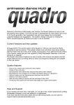
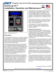
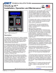
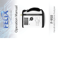
Powered by SYNERTIAL Motion Capture System User Manual Rev. 1.2 3DSuit® Motion Capture System User Manual TM Revision 1.2 Inertial Labs, Inc Address: 39959 Catoctin Ridge Street, Paeonian Springs, VA 20129 U.S.A. Tel: +1 (703) 880-‐4222, Fax: +1 (703) 935-‐8377 Website: www.inertiallabs.com Powered1 by SYNERTIAL Powered by SYNERTIAL Motion Capture System User Manual Rev. 1.2 TABLE OF CONTENT 1.INTRODUCTION…………………………………………………………………………………………………….……….....…3 2.HARDWARE…………………………………………………………………………………………………………….…………...3 2.1.3D ORIENTATION SENSORS……………………………………………………………………………………………….3 2.2.SENSOR BUS MOBILE PROCESSOR UNIT (SB-‐MPU)……………………………………………………..…....5 2.3.SENSOR BUS SPLITTERS (SB-‐SPLITTER)……………………………………………………………………..…….…6 2.4.ANKER ASTRO-‐3E MOBILE BATTERY PACK………………………………………………………………….….….6 2.5.CISCO** LINKSYS E1200 WIFI ROUTER……………………………………………………………………………...6 3.SOFTWARE…………………………………………………………………………………………………………..………………6 4.START-‐UP GUIDE ………………………………………………………………………………………………..……………….7 4.1.SETTING UP THE ROUTER…………………………………………………………………………………….…………...7 4.2.PUTTING ON THE 3DSUIT……………………………………………………………………………….…………….…..9 4.3.INSTALLING THE SOFTWARE…………………………………………………………………………..……………..….9 4.4.RUNNING THE 3DSUIT……………………………………………………………………….…………..………………..10 TM Inertial Labs, Inc Address: 39959 Catoctin Ridge Street, Paeonian Springs, VA 20129 U.S.A. Tel: +1 (703) 880-‐4222, Fax: +1 (703) 935-‐8377 Website: www.inertiallabs.com 2 Powered by SYNERTIAL Motion Capture System User Manual Rev. 1.2 1.INTRODUCTION 3DSuit full body Motion Capture System utilizes 15 (17) inertial 3D orientation sensors that measure real-‐time movements of each major bone segment of the body. From there, with the help of inverse kinematics, the system determines the location of each body joint and applies that to the skeleton of the avatar. Because inertial sensors rely on earth references of gravity and magnetic field, which exist everywhere, the suit itself is then able to operate virtually anywhere and without requiring any pre-‐operation setup. With the introduction of temperature compensation and waterproof housing and cabling, 3DSuit now also offers abilities to work underwater, in rain, in cold or hot weather; almost anywhere a person (or animal) would dare to go. 2.HARDWARE 2.1. 3D MINIATURE ORIENTATION SENSORS – INERTIAL MEASUREMENT UNITS (IMU) The Inertial Labs multi-‐purpose 3D orientation sensors designed for use in real-‐time orientation tracking applications. It includes three types of sensing elements: tri-‐axial MEMS Gyroscopes, tri-‐axial MEMS Accelerometers, and tri-‐axial magneto-‐resistive Magnetometers. The 3D orientation sensors also comes equipped with an onboard processor and embedded orientation algorithms allowing for direct integration into systems without interfacing a PC. Data from the Gyroscopes, Accelerometers, and Magnetometers, as well as the internal temperature sensor are gathered and processed by the on-‐board digital signal processor (DSP). The fusion algorithm processes these data and outputs the final orientation solution directly from the sensor. Data of the following types can be requested: raw inertial sensors data and/or quaternion data. Each 3D orientation sensor module is individually calibrated in a special non-‐magnetic laboratory where reference accelerations, angular rates, and magnetic fields are applied to the device and measured at constant temperature. Additionally, temperature cycling is performed to obtain temperature calibration parameters for the gyro and accelerometer elements. Once fielded, 3D orientation sensor is able to be customer calibrated against soft-‐ and hard-‐iron interference present in the end application. TM Inertial Labs, Inc Address: 39959 Catoctin Ridge Street, Paeonian Springs, VA 20129 U.S.A. Tel: +1 (703) 880-‐4222, Fax: +1 (703) 935-‐8377 Website: www.inertiallabs.com 3 Powered by SYNERTIAL Motion Capture System User Manual Rev. 1.2 3D orientation sensors specifications Parameter Number of sensors in 3DSuit Output signals Units Output update rate (auto transmit) Start-‐up time Heading Range Angular Resolution Static accuracy at constant temperature Dynamic Accuracy Attitude Range: Pitch, Roll Angular Resolution Static accuracy at constant temperature Dynamic Accuracy Noise (@100 Hz) Gyroscopes Gyroscopes measurement range In-‐run Bias Stability at Constant Temperature Bias stability in whole Temperature Range Scale Factor Accuracy Gyroscopes noise Bandwidth Accelerometers Accelerometers measurement range In-‐run Bias Stability at Constant Temperature Bias Stability in whole Temperature Range Scale Factor Accuracy Accelerometers noise Bandwidth Magnetometers Magnetometers measurement range Noise Scale Factor Accuracy Bandwidth Environment Operating and storage temperature range MTBF Environmentally sealed (option) Electrical Supply voltage Power Consumption Connector type Output Interface Physical Size (with single-‐ended connector) Weight Hz sec deg deg deg deg, RMS deg deg deg deg, RMS deg, RMS deg/s deg/s, RMS deg/s, RMS % deg/sec√Hz Hz g mg, RMS mg, RMS % mg√Hz Hz Gauss μG/√Hz % Hz deg C hours V DC W -‐ -‐ mm gram Value 17 Accelerations, Angular rates, Magnetic field, Quaternion 20-‐2000 <1 0 to 360 0.01 1 <2 0 to 360 0.01 0.2 1 0.05 ±1200 or ±2000 0.1 1 0.5 0.03 50 ±2 or ±16 1 3 0.15 0.2 22 ±2.0 150 0.1 20 -‐40 to +85 35,000 IP67 3.5 to 5.5 0.3 Binder 0931117104 TIA/EIA-‐485A (half-‐duplex) 50.7 × 14.5 × 9.2 12 TM Inertial Labs, Inc Address: 39959 Catoctin Ridge Street, Paeonian Springs, VA 20129 U.S.A. Tel: +1 (703) 880-‐4222, Fax: +1 (703) 935-‐8377 Website: www.inertiallabs.com 4 Powered by SYNERTIAL Motion Capture System User Manual Rev. 1.2 2.2.SENSOR BUS MOBILE PROCESSOR UNIT (SB-‐MPU) The Sensor Bus Mobile Processor Unit, SB-‐MPU, is a multi-‐purpose processing platform designed to work with the Inertial Labs 3D orientation sensors. The SB-‐MPU provides power to and receives data from up to 30 simultaneously connected 3D orientation sensors via TIA/EIA 485A serial protocol. The data is logged locally and can be transmitted in real-‐time to the PC via a standard mini-‐USB cable or wirelessly (WiFi). The SB-‐MPU is equipped with hot-‐pluggable connector able to support a combined total of up to 30 orientation sensors and sensor bus extenders (SB-‐Extender) simultaneously. Input supply power is able to be provided by the Inertial Labs Battery Module or an equivalent DC supply. Power is then provided out to all of the connected sensor bus chains. In addition to the currently supported feature set, the SB-‐MPU system is equipped with its own internal GPS receiver allowing for future support of GPS on board. SB-‐MPU specifications Parameter MPU to PC wireless interface MPU to PC for debug console MPU to sensor bus interface Performance Internal Processor DDR Memory Flash Memory Environment Operating temperature Storage temperature Electrical Input supply voltage Output supply voltage Maximum output current Power consumption (no sensors, WiFi off) Power consumption (no sensors, WiFi on) Power consumption (18 sensors, WiFi on) Sensor Bus Interface Standard Baud Rate Byte Size Stop Bites Parity Units -‐ -‐ -‐ -‐ -‐ degC degC V V mA mW mW mW -‐ bps bits bits -‐ Value 802.11a/b/g/n or Bluetooth Virtual Serial Port over miniUSB, 115200/8/noPar/1/noFC TIA/EIA-‐485A Up to 1GHz (TI DM3730) 512MB, 200MHz Mobile DDR SDRAM 512MB, NAND flash memory +uSD card slot, up to 64GB 0 to +85 -‐40 to +85 6.0 to 15.0 5±2% 3000 500 1500 7000 TIA/EIA-‐485A (half-‐duplex) 1000000 8 1 No TM Inertial Labs, Inc Address: 39959 Catoctin Ridge Street, Paeonian Springs, VA 20129 U.S.A. Tel: +1 (703) 880-‐4222, Fax: +1 (703) 935-‐8377 Website: www.inertiallabs.com 5 Powered by SYNERTIAL Motion Capture System User Manual Rev. 1.2 2.3. SENSOR BUS SPLITTERS (SB-‐SPLITTER) The Inertial Labs Sensor Bus Splitter (SB-‐Splitter) splits a single TIA/EIA-‐485 data bus into 3 TIA/EIA-‐485 buses. Intended for use with Inertial Labs 3D orientation sensors, the SB-‐Splitter supports the connection of multiple chains of devices to a single data acquisition and transmission unit such as the Inertial Labs SB-‐CU-‐W915, wireless controller, or the SB-‐CU-‐USB direct PC connection. 2.4. ANKER ASTRO-‐3E MOBILE BATTERY PACK Anker Astro* is a line of portable external batteries designed for our modern mobile age. High capacity power and compact designs make these batteries a reliable power companion on the go. • • • * Astro is a trademark of Company ASTRO • • Features: 10000 mAh of capacity; Charges one device at maximum speed or two at 3A total; A lightweight, unassuming solution to life's daily power needs (0.59in thick). LEDs display just how much juice you've got left. Reliable lithium polymer core ensures quality, supplying you with more than 500 charge cycles during the course of its life; Input: 5V / 1.5A Package contents: Anker Astro 3E External Battery, 4 adapters, USB wire and travel pouch. 2.5. CISCO** LINKSYS E1200 WIFI ROUTER The Cisco** Linksys E1200 is one of the latest and best-‐ reviewed basic Wireless-‐N routers, and it is no wonder why given its speeds of up to 300 mbps at this very affordable price. With up to 300 Mbps Wireless-‐N speeds (up to 6x faster than a Wireless-‐G router) and 4 fast Ethernet ports for wired connections. ** CISCO is a trademark of Company CISCO 3. SOFTWARE Features: • Kinematics Skeleton Software • Easily record motion capture data • Export to *.bvh format • Real-‐time visualization, playback and editing of motion capture data • Plug-‐in for seamless real-‐time integration with MotionBuilder® & Unity® MotionBuilder® & Unity® are Trademarks of Autodesk and Unity TM Inertial Labs, Inc Address: 39959 Catoctin Ridge Street, Paeonian Springs, VA 20129 U.S.A. Tel: +1 (703) 880-‐4222, Fax: +1 (703) 935-‐8377 Website: www.inertiallabs.com 6 Powered by SYNERTIAL Motion Capture System User Manual Rev. 1.2 4. START-‐UP GUIDE 4.1. SETTING UP THE ROUTER • Connect the Router (LAN 1) directly to the Ethernet port on your PC. If an internet connection is simultaneously required you must also connect a secondary Ethernet cable from an external internet source to the WAN port. • Plug in the router and let it run through it's power up cycle. • Your computer will detect the LAN network. You can go to Control Panel/Network Connections to view your networks. Double click on the newly discovered network in Network Connections and go to Properties. Under the General tab you will find a scroll-‐down list. Scroll down to Internet Protocol (TCP/IP), highlight and click Properties to check that both IP address and DNS server are set to obtain automatically. TM Inertial Labs, Inc Address: 39959 Catoctin Ridge Street, Paeonian Springs, VA 20129 U.S.A. Tel: +1 (703) 880-‐4222, Fax: +1 (703) 935-‐8377 Website: www.inertiallabs.com 7 Powered by SYNERTIAL • Motion Capture System User Manual Rev. 1.2 To check that the computer has recognised the device you can open a command terminal (type CMD into Run as found in your Start bar) and Ping the router by typing: Ping 192.168.11.1 If there is no reply (Request timed out) from the router then the PC requires a reboot. The network adapter card could also be turned off. When you get a reply from the router you can also Ping the MPU. Switch the MPU on. Wait about 60 seconds and type: Ping 192.168.11.xx (where xx is the MPU number found on the front of the device i.e. 30) Note: In situations where you are unable to ping the MPU please navigate to the router settings page via any browser at 192.168.11.1. Under LAN Interface / Show Clients you should be able to see all active wireless devices and this will allow you to double check the IP addresses of the MPU. If you continue to encounter connection issues then please check that there are no other wireless routers on in the vicinity that could be creating interference by connecting to the MPU. Switch off these other devices temporarily to see if they have any effect. TM Inertial Labs, Inc Address: 39959 Catoctin Ridge Street, Paeonian Springs, VA 20129 U.S.A. Tel: +1 (703) 880-‐4222, Fax: +1 (703) 935-‐8377 Website: www.inertiallabs.com 8 Powered by SYNERTIAL Motion Capture System User Manual Rev. 1.2 4.2. 3DSUIT MAGNETIC DEVIATION COMPENSATION (MDC) Each 3DSuit Systemis individually calibrated in a special non-‐magnetic laboratory where reference accelerations, angular rates, and magnetic fields are applied to the device and measured at constant temperature. Additionally, temperature cycling is performed to obtain temperature calibration parameters for the gyro and accelerometer elements. Once fielded, 3DSuit is able to be customer calibrated against soft-‐ and hard-‐iron interference present in the end application. What is MDC? When a 3DSuit is operating in an open area in the absence of any ferrous metals there is no distortion effects on the earth's magnetic field. In reality, sensors are mounted on objects that most likely have ferrous materials nearby. The effects of ferrous metals will distort, or bend, the earth's field, which will alter the heading. These effects can be thought of as a magnetic field that is added to the earth's field. If the sensor is securely mounted in an object, the ferrous effects can be accounted for and removed from the magnetic readings. The current guide describes the procedure of how to compensate such magnetic deviations using the MDC application. Before You Begin The MDC application can be run via SB-‐CU-‐USB. Should you run into problems establishing the initial connection to the sensor upon startup of MDC please contact us via phone at +1-‐703-‐880-‐4222 or via email at [email protected]. MDC Instructions Please run MDC according attached MDC instruction. It will take no more than 5 minutes to complete MDC and to reach 3DSuit best performance. 4.3.PUTTING ON THE 3DSUIT WITH EMBEDDED SENSORS - putting on the 3DSuit; - connect long sleeve shirt (upper part) and pants (lower part) by two binder connectors. 4.4. INSTALLING THE SOFTWARE • Place the 3DSuit Software packs folders we have provided you onto your Desktop (or elsewhere as you decide more appropriate) and open them. • Open the Install folder, and choose either 32-‐Bit or 64-‐Bit according to which you have installed on your operating system. Open the chosen folder and run either Setup32 or Setup64, whichever is in your folder. TM Inertial Labs, Inc Address: 39959 Catoctin Ridge Street, Paeonian Springs, VA 20129 U.S.A. Tel: +1 (703) 880-‐4222, Fax: +1 (703) 935-‐8377 Website: www.inertiallabs.com 9 Powered by SYNERTIAL • Motion Capture System User Manual Rev. 1.2 Follow the steps on the wizard shown until you get to the Choose Components screen. Here, choose either wired suit or wireless suit, according to what was purchased. • After clicking next on the choose components screen, choose where to install the software. The default install location is “C:\\Program Files\Animazoo” • After choosing your install path, you will get the Keylock Security Key Installation screen. Here, choose Keylock 3 or Fortress (USB Driverless), installation type Standalone. • Once the installation is done, click finish • To check installation, run AnimaFake and look for ‘Normal’. • To restart your PC Note: If the command window closes itself please manually place GyroDrv.sys into C:\WINDOWS\system32\drivers and Animazoo.dll into C:\WINDOWS\system32 4.5. RUNNING THE 3DSuit 4.5.1 CONNECT THE ANKER ASTRO-‐3E MOBILE BATTERY AND SENSORS BUS TO THE SB-‐MPU. TM Inertial Labs, Inc Address: 39959 Catoctin Ridge Street, Paeonian Springs, VA 20129 U.S.A. Tel: +1 (703) 880-‐4222, Fax: +1 (703) 935-‐8377 Website: www.inertiallabs.com 10 Powered by SYNERTIAL Motion Capture System User Manual Rev. 1.2 The order is: Lights 1 + 2 will come on instantly and stay steady waiting for the 3rd light. Light 3 will come on flashing and when it stops flashing, the 5 router is connected and will automatically go to the next light 4 3 2 1 Light 4 is not used and will stay un-‐lit Light 5 will come on flashing and when it stops flashing the SB-‐MPU has begun broadcasting stream of data in Wi-‐Fi 4.5.2 THEN OPEN THE WIRELESS SERVER (OR ETHERSUIT.EXE) AND ACCEPT BY CLICKING OK • To run Ethersuit.exe, use windows explorer to go to where you installed the software (default C:\\Program Files\Animazoo), open the install folder, and launch Ethersuit.exe. • If there is no suit detected, make sure you are on the correct network and the suit is turned on. You can find the suit again by going to File -‐> choose suit • After choosing the suit, Ethersuit should display “Pumping ‘IP …’” •If Ethersuit pops up with the error “Could not create enough pipes”, open up the command prompt in administrator mode (found under start -‐> accessories -‐> command prompt (rightclick -‐> run as administrator)) and type in “net start gyrodrv” •After 5-‐30 seconds, the command prompt will respond with “The gyroDRV service was started successfully”. If this message does not appear, verify that you installed the correct version of animazoo (32 or 64 bit). Once this message has appeared, you will be able to choose a suit successfully. TM Inertial Labs, Inc Address: 39959 Catoctin Ridge Street, Paeonian Springs, VA 20129 U.S.A. Tel: +1 (703) 880-‐4222, Fax: +1 (703) 935-‐8377 Website: www.inertiallabs.com 11 Powered by SYNERTIAL Motion Capture System User Manual Rev. 1.2 4.5.3 OPEN ANIMADEMO PROGRAM 4.5.4 FINALLY FACE SOUTH IN THE INITIALIZATION POSTURE AND PRESS 'N' 4.5.5 CHECK YOUR REAL-‐TIME REFERENCE MODEL 4.5.6 PRESS «ALT + R» TO START RECORDING 4.5.7 PRESS «ESC» TO STOP 4.5.8 PRESS «P» TO REPLAY. NOTE: Make sure to save before recording the next take! Tips for Starting the 3DSuit • For continued good battery life we recommend running the SB-‐MPU battery to empty and then fully charging whenever the opportunity arises. • You will need to start the suit in clear line-‐of-‐site of the router. It is best to be stood about 4 feet away from the router during start up. • Find a Magnetically Cleaning Space Use the provided compass to check for magnetic interference at foot height, waist height and head height. Be on the look-‐out for air-‐conditioning units, power points, large metal objects or anything passing large electrical current. You will need to Start the 3DSuit and 'North' in the 'magnetically cleanest' area possible. • Stand still for Initialization • Find north needed for initialization This can be done with the compass that's provided or by a series of trial and error moves. By this I mean: • Estimate which direction is South • 'South' the 3DSuit by pressing «N» on the keyboard (or going Actions/Set North) whilst in AnimaDemo • Lean forward as if bending to touch your toes to see if your shoulder alignment is straight or not. Judging by the slope of shoulders you will be able to re-‐South until you find the correct direction. • Use the T shortcut to switch to 'top-‐down' view in AnimaDemo. This will help you discover whether or not when you lean forward your shoulders and spine are straight. This may sound like a lengthy process, but you will soon turn it into a quick one. TM Inertial Labs, Inc Address: 39959 Catoctin Ridge Street, Paeonian Springs, VA 20129 U.S.A. Tel: +1 (703) 880-‐4222, Fax: +1 (703) 935-‐8377 Website: www.inertiallabs.com 12 Powered by SYNERTIAL Motion Capture System User Manual Rev. 1.2 Note: It is good practicse to re-‐South prior to each recording you take therefore we would suggest that once you have located your South direction you mark the floor with masking tape or similar as a quick point of reference. System Maintenance To ensure you get the best performance from your 3DSuit we’ve put together a simple list of do’s and dont’s. Do: • Drain your batteries often, if you can, before each charge. Leaving it on the charger indefinitely will reduce their life significantly. Take it off the charger as soon as the light is green • Wash the Lycra 3DSuit in cold water and hang to dry • Leave system in its case to avoid moisture and dust. Don’t: • Ensure that the 3D orientation sensors -‐ aren’t knocked by hard objects or dropped on hard floor. This can affect the 3D orientation sensors -‐ factory pre-‐set calibration and will mean it has to be sent for recalibration. • Don't let any part of the system get wet. • Do not close the case with sweaty suit inside. Let it dry first. • Don't pull cabling off the Lycra suit. Use the the 3D orientation sensors casing to pull it off the cloth. Ensure that Velcro patch is off the 3DSuit before pulling the casing off the Lycra suit. • Careful when closing the hard case so as not to trap/damage any of the cabling. Setting up your hardware The main components of your system’s hardware include 17 inertial 3D orientation sensors, cabling, SB-‐ MPU and two SB-‐Splitters. It is vital that the 3D orientation sensors -‐ are accurately placed to best avoid known data artefacts to achieve the best data possible from your system. TM Inertial Labs, Inc Address: 39959 Catoctin Ridge Street, Paeonian Springs, VA 20129 U.S.A. Tel: +1 (703) 880-‐4222, Fax: +1 (703) 935-‐8377 Website: www.inertiallabs.com 13 Powered by SYNERTIAL Motion Capture System User Manual Rev. 1.2 3D Orientation Sensors Placement The diagram below depicts the correct anatomical placement of each sensor: NOTE: -‐ place sensors on the upper legs (# 3 & 0) and upper arms (# 13 & 7) as shown by Red markers above. However when the subject has large muscles on those limbs, use the blue marker placements to insure the most accurate capture of motion; -‐ sensors #6, 12 and 17 are for 18 3D orientation sensors 3DSuit model. Enjoy your 3DSuit Motion Capture System! TM Inertial Labs, Inc Address: 39959 Catoctin Ridge Street, Paeonian Springs, VA 20129 U.S.A. Tel: +1 (703) 880-‐4222, Fax: +1 (703) 935-‐8377 Website: www.inertiallabs.com 14