1
Quick Start Instructions
xi
Quick Start Instructions
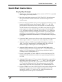
Step by Step Example
1. With the power button in the Standby position, connect the CG635 to a grounded
outlet using the power cord provided.
2. Push in the power button to turn on the CG635. The CG635 will perform some
start up tests and then recall the instruments’ last known settings from non
volatile memory.
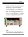
3. Reset the CG635 to its default state by pressing sequentially the following 3 keys
located in the ENTRY section of the front panel: ‘SHIFT’, ‘+/-’, ‘Hz’. This
performs the INIT function which resets the instrument to its default settings.
The INIT function will set the frequency to 10 MHz, set the phase to 0 degrees,
set the output levels for Q and Q̄ to LVDS, set the output levels for CMOS to
3.3 V, and select the frequency for display. The LVDS and +3.3 V LEDs in the
OUTPUT LEVELS section of the front panel should be on. The FREQ LED in
the DISPLAY section should be on. The seven segment display should show
10.000000000 and the MHz LED should be lit. This indicates that the frequency
is 10 MHz.
4. Connect the CMOS output to an oscilloscope with a high impedance input to see
that the output is indeed a 3.3 V square wave with a frequency of 10 MHz.
5. Adjust the frequency to 5 MHz by pressing the following keys sequentially: ‘5’,
‘MHz’. The display should change to 5.000000000 MHz. The oscilloscope
should now display a 5 MHz square wave with amplitude 3.3 V.
6. Adjust the CMOS output up to 5.0 V by pressing the CMOS ▲ key in the
OUTPUT LEVELS section of the front panel. The +3.3 V LED should turn off
and the +5.0 V LED should turn on. The oscilloscope should now display a
5 MHz square wave with amplitude 5.0 V.
7. Press the ‘CMOS HIGH’ key in the DISPLAY section of the front panel. The
CMOS HIGH LED should turn on and the seven segment display should show
5.00 VDC.
8. Adjust the CMOS output to 4.5 V by pressing the following keys sequentially in
the ENTRY section of the front panel: ‘4’, ‘.’, ‘5’, ‘VOLT’. The seven segment
display should now show 4.50 VDC. In the OUTPUT LEVELS section, the
+5.0 V and VAR LEDs should be lit. This indicates that the current CMOS
output voltage varies from, but is closest to the +5.0 V standard output level.
9. Press the CMOS ▼ key in the OUTPUT LEVELS section of the front panel. The
CMOS output changes to the nearest standard level in the direction of the
indicated key, which is 3.3 V in this case. The VAR LED should turn off,
indicating that the current output is at a standard level.
CG635 Synthesized Clock Generator