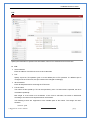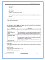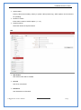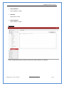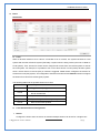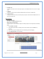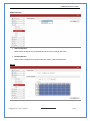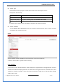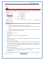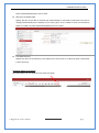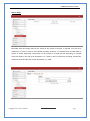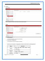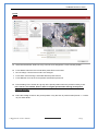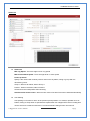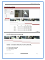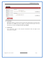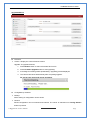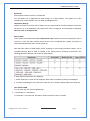
1
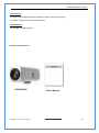
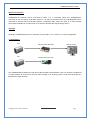
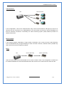
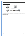
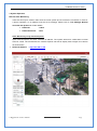
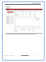
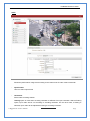
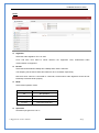
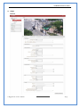
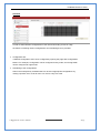
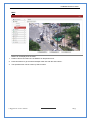
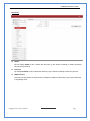
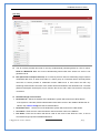
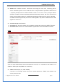
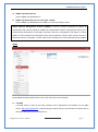
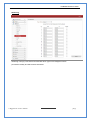
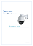
2 Megapixel IP Box Camera X20 Zoom CMOS, 1080P @60fps User Manual ver.1.0 TN-B220CSA user manual Safety Precaution We appreciate your purchasing TN series. Before installing the product, please read the following with care. Make sure to turn off the power before installing TN-B220CSA Do not install under the direct sunlight or in dusty areas. Make sure to use the product within the temperature and humidity specified in the specification. Do not operate the product in presence of vibrations or strong magnetic fields. Do not put electrically conducting materials in the ventilation hole. Do not open the top cover of the product. It may cause a failure or electric shock on the components. To prevent from overheating, make sure to keep the distance at least 10cm from the ventilation hole. Make sure proper voltage (220V/100V) before connecting the power. 2 Megapixel IP Camera Manual 2/75 TN-B220CSA user manual 1. Introduction About this manual This User Manual provides information on operating and managing the megapixel IP box camera. The Manual includes instructions of installation, operation and configuration of megapixel IP box camera as well as how to make troubleshooting. Features This product is a megapixel Box network-based camera with remote live monitoring, audio monitoring and control via an IP network such as LAN, ADSL/VDSL, and Wireless LAN. Video Highly efficient compression algorithm, H.264 & MJPEG support Wide range of transmission rates: 32kbps ~ 16mbps Various transmission modes: CBR, VBR, Hybrid Motion detection Audio Multi-transmission mode: Simplex (IP Box camera Client PC or Decoder, Client PC or IP Box camera), Full Duplex Decoder Network Fixed IP & Dynamic IP (DHCP) support 1:1, 1:N support Multicasting Various types of Protocol support : TCP/IP, UDP, Multicast, DHCP, SMTP, HTTP, SNMP, RTP, RTSP OnVIF, PSIA compliant Serial Data RS-485 support Data pass-through mode : Serial data communication between megapixel IP PTZ camera and Decoder Sensor and Alarm Support direct connections of external sensor and alarm devices Event Alarm notification. If an external sensor is activated, camera can be set to move to the corresponding Preset position. 2 Megapixel IP Camera Manual 3/75 TN-B220CSA user manual User Interface Diagnose and upgrade through dedicated program called True Manager System configuration using Internet Explorer High Reliability Reliable embedded system Product and Accessories TN-B220CSA 2 Megapixel IP Camera Manual Quick Manual 4/75 TN-B220CSA user manual Part Names and Functions Rear ① ② ③ ④ ⑤ ⑥ ⑧ ⑦ ⑨ Connector 1. Ethernet/802.3af Function Ethernet port/802.3af LED : Booting and system check 2. RESET Button Initialization of network setting 3. AUDIO IN Audio input 4. AUDIO OUT Audio output 5. POWER IN DC 12V 6. SENSOR/ALARM Sensor input/ Alarm output 7. RS-485 RS-485 port 8. VIDEO OUT Composite / HD-SDI / HDMI Video output (Depending on models) 9. SD CARD 2 Megapixel IP Camera Manual SD memory card slot 5/75 TN-B220CSA user manual System Connections TN-B220CSA.IP Cameras can be connected in either 1 to 1 connection where one TN-B220CSA.is connected to one PC client or a decoder system or 1 to many connections where one TN-B220CSA.can be connected to several PCs and decoder systems. (TCS-2000 video server can work as a video decoder which takes the data from a video server or IP camera, decodes and outputs analog video.) Topology Generally, TN-B220CSA.and PC or a decoder is connected in 1-to-1 mode or 1-to many configuration. 1:1 Connection . Site Site Remote Center (Decoder) Remote Center Remote Center (PC SW) One TN-B220CSA.is installed at a site where video images are transmitted. A PC or a decoder is installed at a central location to receive and view the video images on an analog monitor. Audio and serial data are transferred in either direction. 2 Megapixel IP Camera Manual 6/75 TN-B220CSA user manual 1:N Connection . Site Remote Center or or or In this configuration, a site can be monitored from many remote central locations. Although up to 64 PCs or decoders can be connected to one TN-B220CSA in the real network environment, network bandwidth can limit the maximum connections. Functionally, the video monitoring system (VMS) software provided can replace the decoder. Multicast Mode If the network supports multicasting, a large number of decoders can be used to receive video effectively from a TN-B220CSA.using a single streaming of video and audio. However, multicast mode is possible only when network environment supports multicast. Relay Site Center 1(Decoder) Center 2 (Decoder) Video and audio data can be retransmitted from a center to another center. The arrangement is useful when the network bandwidth to the site is limited while there are more than one center want to monitor the site. 2 Megapixel IP Camera Manual 7/75 TN-B220CSA user manual VMS (Video Monitoring System) Site Site Remote Center Remote Center (Decoder) VMS VMS (Video Monitoring System) is a Window-based remote monitoring program in order to monitor or control video, audio, and events in real time from several IP cameras or video servers. Please refer to the VMS User Manual for more in detail. 2 Megapixel IP Camera Manual 8/75 TN-B220CSA user manual 2. Installation Connection Connecting Power 1. Carefully check the voltage and current capacity of the rated power. The rated power is indicated in the back of main unit. 2. After confirming the power source, connect power adaptor and connect the 12V DC connector to the system Connecting Network 1. Plug network cable to Ethernet port (RJ-45 network port). Connecting Video 1. To display video through the composite or HD-SDI port, connect each port to a monitor using BNC coaxial cable. To display video through the HDMI port, connect the port to a monitor using HDMI cable. 2. Set Enable Preview option “ON” on the Video tab of web page. (Please refer to the Video Configuration part) Especially in case of using HD-SDI, video cannot be viewed if BNC coaxial cable is not used. In case that video transmission distance is long, video data may not be transmitted due to a reduction in the video signal. In order to prevent it, install a repeater in the middle. In case of using HD-SD I, video can be viewed on the HD-SDI monitor In case of using HDMI, video can be viewed on the monitor supporting HDMI Connecting Audio Audio is full-duplex. It is possible to set the mode as Tx-only, Rx-only or Tx-Rx. 1. Connect audio input and output ports to audio devices accordingly. 2. The Audio signal required is line level, so an audio equipment with an amp, mixer or other amplifier should be used. Connecting Serial Port (RS-485 Communication) RS-485 of TN-B220CSA can be connected to external equipment such as PT receiver etc. PC client can send PT commands to the external equipment via the serial port. When a decoder system instead of PC client is connected to TN-B220CSA the serial port and that of the decoder system works in pass-through mode. That is, data from at one port is delivered to the other port, vice versa 2 Megapixel IP Camera Manual 9/75 TN-B220CSA user manual Connecting Sensor and Alarm Connect sensor and alarm devices to corresponding terminals accordingly Check if it works Once the power is supplied to the camera, it will start booting. The system will boot up to an operating mode after approximately 40-60 seconds. The green LED on the Ethernet port will flash indicating the system is ready. The software provided in the CD called True Manager allows you to check the IP address and other network details of the camera. Please refer to the True Manager manual for instructions on how to find the IP address of the camera and change it if required. 2 Megapixel IP Camera Manual 10/75 TN-B220CSA user manual 3. System Operation Remote Video Monitoring There are two ways to monitor video when the center system and IP camera are connected. In order for a proper operation, an IP address must be set accordingly. Please refer to True Manager Manual enclosed with product for further details. Default ID : admin Default Password :1234 Video Monitoring using Internet Explorer Open Internet Explorer and enter camera’s IP address. The system will ask for confirmation to install Active-X control. Once authorized, the Internet Explorer will start to display video images from camera as shown below. Defalut IP Address : http://192.168.10.100 2 Megapixel IP Camera Manual 11/75 TN-B220CSA user manual Video Select Select the Video stream to be viewed : Primary, Secondary, tertiary or quartic streaming. This camera is capable of dual streaming; primary streaming and secondary streaming..Video will be displayed according to the resolution set on video configuration. If dual streaming (“Use Dual Encode” Menu in Video page) is not activated, secondary video is not available View Size Adjust the size of the screen. Screen size if initially adjusted according to the compression resolution. Click on 50% icon and the whole screen size will be reduced to half size. Digital Zoom Control the Digital zoom on the screen The more the camera zooms in, the smaller the square of control panel is. Position of the image can be changed by moving position of the square. If you press x1, the screen will return to the normal size. PTZ Control (Optical Zoom & Digital Zoom Built-in the Camera) Control PTZ and PTZ Control Panel is used for controlling external PTZ devices when the external PTZ devices are connected through serial port. It is possible to make zooming control by Zoom in/out 2 Megapixel IP Camera Manual 12/75 TN-B220CSA user manual buttons of PTZ control Panel (In order to use digital zoom, select Digital zoom ON in the Camera tab) - Stop Stop on-going action - Focus Near, Focus Far, Auto Focus Adjust the focus of the lens Select Preset Set preset position and move to the specific preset position. - Goto Move to the selected preset entry if the preset entry is set. - Set Set the current position to the selected preset entry. - Clear Delete the selected preset entry. Sensor Input and Alarm Output Display the status of the sensor in real time. This camera supports one sensor input. When the sensor of the camera is working, the sensor light turns red Operate the alarm device by pressing the number icon. This camera supports one alarm output. A number icon indicates status of the alarm device. Snapshot Capture video images and store them as BMP or JPEG files. Talk Transfer audio from PC’s mic to the camera. 2 Megapixel IP Camera Manual 13/75 TN-B220CSA user manual File Record Recording to an AVI file on Live View page is available. AVI files are generated in the specified folder or in a specified file name on the PC where web browser is running. 1. Press “Set” button to select a folder or create a new folder. Enter the file name on a filename field. 2. Press “Start” button to start recording. 3. Press “Stop” button to stop recording. 4. An AVI file named “IP address_hh_mm_ss” or “File name_IP address_hh_mm_ss” will be generatedin the specified folder depending on where the path specified folder or a prefix of the file name. Display Buffer Set the number of video frames to be buffered before being displayed on web browser. Larger value results in smoother video by sacrificing the latency. A setting of 10 ~ 15 frames can be used generally for most situations. Video Monitoring with Decoder System Once camera’s IP address is set in the remote IP address section of the decoder, the decoder system will connect to camera and start receiving the video images. Normally, a monitor connected to the decoder will display video images Initialize of IP Address If a system IP address is lost, the system can be reset to the system default IP address using the reset button in the back side of the system. 1. While the system is in operation, press the reset button for more than 5 seconds. 2. The system will reboot automatically. 3. Once the system reboots, IP address will be set to the system default as below; IP mode Fixed IP IP address 192.168.10.100 Subnet mask 255.255.255.0 Gateway 192.168.10.1 Base port 2222 HTTP port 80 2 Megapixel IP Camera Manual 14/75 TN-B220CSA user manual 4. Remote Configuration Using Web Browser Remote setting is available by using web browser. Enter IP address of camera and then a live view screen appears as below. Press Setup button located in the upper right area of the monitoring screen to go to the server setup. For Remote Setting, user should be authorized higher than manager level. Enter IP Address Press Setup button The configurations are grouped into 9 categories: Video & Audio, Image, Network, Event, Record, Device, PTZ, System, User. Leaving the page without pressing Apply button, any changes in the page will be discarded. 2 Megapixel IP Camera Manual 15/75 TN-B220CSA user manual Video & Audio Information The information provides current information regarding the settings for video and Audio 2 Megapixel IP Camera Manual 16/75 TN-B220CSA user manual Video - Performance Calculation Shows the performance usage rate according to the value set at ‘Encode’ mode underneath. - Input Format User can select input format - Resolution Select video encoding solution. Scaling option is used when encoding resolution is different from input resolution. Without Scaling option, input video will be cut according to encoding resolution. On the other hand, if Scaling is selected, input video will be adjusted according to encoding resolution. 2 Megapixel IP Camera Manual 17/75 TN-B220CSA user manual - Framerate Determine the maximum number of frames per second for the video stream. 1,2,3,4,5,6,8,10,15,20,25, 30 and 60 frame rate can be selected. The actual frame rate of video can be less than the maximum frame rate set due to the network bandwidth limitation - Preference Select encoding mode to control video quality or bitrate: Quality(VBR) or Bit rate(CBR). If ‘Bitrate’ selected, the video encoding will be effected by the ‘Bitrate’ value entered. Therefore, “Bitrate” mode corresponds to CBR (Constant Bit rate) encoding. If ‘Quality’ selected, the video encoding will be effected by the quality of image selected. Therefore, “Quality” mode corresponds to VBR (Variable Bit Rate) encoding. - Quality Select Video quality. 7 levels of quality are available. Quality mode (VBR encoding) tries to encode every frame in a constant quality. Therefore, resulting bitrate may vary a lot depending on the complexity or activity changes in the input video. It is preferred when constant video quality is required and network bandwidth is enough for delivering the stream of highly varying bitrate. - Bitrate Determine bitrate value between 32 ~ 16Mbps. Bitrate mode (CBR encoding) allows you to set a fixed target bitrate that consumes a predictable amount of bandwidth. In order to keep the bitrate limit, video quality is controlled dynamically according to the complexity or activity changes in the input video. - I-Frame Interval Determine I-frame Interval between 1 and 255. - H.264 Profile Select H.264 Profile : High Profile or Baseline Profile The standard defines various sets of capabilities which are referred to as profiles, targeting specific classes of application. I. High Profile The Primary profile for broadcast and disc storage applications, particularly for high-definition television application. 2 Megapixel IP Camera Manual 18/75 TN-B220CSA user manual II. Baseline Profile Primarily for low-cost applications that require additional data loss robustness, this profile is used in some videoconferencing and mobile application. This profile includes all features that are supported in the constrained baseline profile, plus three additional features that can be used for loss robustness. - Secondary #1 ~ #3 - Use Dual Encode Select ON to enable to use Secondary #1 ~ #3. The Secondary #1 ~ #3 video can be viewed on Live View window by selecting Stream number on Video selection - ROI Encoding Select ON to enable to use ROI. User can make an area for ROI on Secondary stream. - Algorithm Select H.264 or MJPEG for the secondary, tertiary or quartic streaming. In case of H.264, wither bitrate mode or Quality mode can be selected for Preference mode in. On the other hand, MJPEG supports Quality mode3 2 Megapixel IP Camera Manual 19/75 TN-B220CSA user manual Audio Algorithm Select the audio algorithm: G.711 or AAC G.711 and AAC from client to server direction are supported. Thus, bidirectional audio communication is supported. Bit rate Select the bitrate between 64Kbps and 128kbps when AAC is selected The sampling rate is fixed to 8KHz and 32KHz for G.711 and AAC respectively. Note that when camera is connected to a decoder, the decoder’s audio algorithm should be set identically to transmit audio properly. Mode Select audio operation mode Mode Action Off No operation Tx-Only Transmit only Rx-Only Receive only Tx & Rx Transmit and Receive Input Gain Set audio input gain from 0 to 31. 2 Megapixel IP Camera Manual 20/75 TN-B220CSA user manual Output Output Format Select the format of output when Enable Preview is selected. Audio Output Audio Output: The input audio is transmitted to the encoder Loopback: Does not transmit the audio to the encoder. Audio input and output at the camera. 2 Megapixel IP Camera Manual 21/75 TN-B220CSA user manual Image General 2 Megapixel IP Camera Manual 22/75 TN-B220CSA user manual Day & Night The camera delivers color images during the day. As light diminishes below a certain level, the camera can automatically switch to night mode (Black & White mode) to maintain good image quality. Day & Night Mode can be selectable according to environment. Auto : Automatically switches to Day (Color) or Night(B&W) according to light using ICR (Infrared Cut filter Removable) Day (Color) : Deliver color image regardless of light. Night (B/W) : Deliver B/W image regardless of light White Balance White Balance has the following modes. - Auto: This mode computes the white balance value output using color information from the entire screen. It outputs the proper value using the color temperature radiating from a black subject based on a range of values from 3000 to 7500K - Manual: Manual control of R and B gain, 256 steps each. - ATW (Auto Tracking WB) : Auto Tracking White balance (2000K to 10000K) Indoor : 3200K Base Mode Outdoor : 5800 K Base Mode Outdoor auto : This is an auto white balance mode specially for outdoors. It allows you to capture images with natural white balance in the morning and evening. Auto Exposure AE Mode - Full Auto: Auto Iris and Gain, Fixed Shutter Speed (59.94/NTSC:1/60 sec, 50/PAL: 1/50 sec) - Iris Priority: 18 steps (F1.8 to Close) of Iris can be set manually. The Shutter Speed and Gain are set automatically, according to the brightness of the subject. - Bright: The bright control function adjusts both the Gain and Iris using an internal algorithm according to a brightness level freely set by user. Exposure is controlled by Gain when dark and by iris when bright. As both Gain and Iris are fixed, this mode is used when exposing at a fixed camera sensitivity. Shutter Priority: 21 steps (1/2 ~ 1/10,000) of Shutter Speed can be set manually. The Iris and Gain are set automatically, according to the brightness of the subject. DSS Mode Manual: 21 steps of Shutter, 18 steps of Iris and 8 steps of Gain can be set manually. Select Auto to operate DSS (Digital Sutter Speed) Back Light Compensation It is an ability of a camera to balance the lighting in a scene with an extremely bright background such as sunlight. It helps to obtain the finest light contrast and get clear image. 2 Megapixel IP Camera Manual 23/75 TN-B220CSA user manual Gamma Mode Gamma correction can be changed in this mode. Highlight correction A function to adjust AE and AF, and to perform the masking of light area as required when a high intensity spot light is detected. It allows you to easily read the number of vehicles and number place in the indoor parking area or in the outdoor during the night Auto Focus Minimum Focus Length Determine to use Digital zoom (12x) supported by the camera zoon lens. x10 Optical zoom and x12 Digital zoom lens (f=5.1 ~ 5.1mm) is built-in TCAM-570-X10S. AF Sensitivity - Normal : Reaches the highest focus speed quickly. Use this when shooting a subject that moves frequently. Usually, this is the most appropriate mode. - Low : Improves the stability of the focus. When the lighting level is low, the AF function does not take effect, even though the brightness varies, contributing to a stable image Focus Offset Placing a dome cover in front of the camera may cause the focal distance of the camera to change. Especially at the tele end, this effect exceeds the AF range, so focus cannot track, although it responds to changes in this value Enhancement WDR The Wide Dynamic Range mode is a function for dividing an image into several blocks and correcting blocked-up shadows and blown-out highlights in accordance with the intensity difference. It enables you to obtain images in which portions ranging from dark to light can be recognized, even when capturing a subject with a large intensity difference that is backlight or includes extremely light portions. Noise Reduction The NR Function removes noise (both random and non-random) to provide clearer images. This function has six steps: levels 1 to 5, plus off. The NR effect is applied in levels based on the gain, and this setting value determines the limit of the effect. In bright conditions, charging the NR level will not have an effect Stabilizer Mode Switching On the image stabilizer function reduces image blurring cause by, for example, vibration, which allows you to obtain images without much blurring. 2 Megapixel IP Camera Manual 24/75 TN-B220CSA user manual Defog Mode When the surrounding area of the subject is foggy and low contrast, the defog mode will make the subject appear clearer Aperture Control Aperture Control is a function which adjusts the edge enhancement of objects in the picture. There are 16 levels of adjustment, starting from “no enhancement”. When shooting text, this control may help by making them sharper. Color Gain User can configure the color gain. Use this setting when bright color is particularly important. The initial setting 1000% can be set to range from approx.. 60% to 2000% with 15stages High Sensitivity In the mode, the maximum gain increases, enabling to obtain a brighter output even in a darker environment, However, if the gain reaches high level (up to 4x), the image will have a large amount of noise ETC Digital Zoom Determine to use Digital zoom (12x) supported by the camera zoom lens. x10 Optical zoom and x12 Digital zoom lens (f=5.1 ~ 5.1mm) is built-in TCAM-570-X10S. Image Flip Select On to enable image to be shown flipped. Mirror Select On to enable image to be shown mirrored. Chroma Suppress User can configure a chroma suppress mode for low-illumination conditions. This can be useful when color noise is particularly noticeable in such conditions. Four levels(disable and three levels) are available for the low-illumination chroma suppress mode. Codec Brightness Controls input video brightness by selecting values between 0 and 255. Contrast Controls input video contrast by selecting values between 0 and 255. 2 Megapixel IP Camera Manual 25/75 TN-B220CSA user manual Saturation Controls input video saturation by selecting values between 0 and 255 Noise Filter Noise Filter (NR) is used in order to obtain a high quality output image and enhance compression efficiency. This camera offers Edge Preserving 2D NR and Motion Adaptive 3D NR. 2D : start to work 2D NR at night mode according to TDN (turn on 2D NR) 3D#1 : start to work 3D#1 NR (refer to 1frames on 3D NR) 3D#2 : start to work 3D#2 NR (refer to 2frames on 3D NR) Strong : start to work 3D NR (refer to 2frames on 3D NR) Increase effects than 3 times comparing with normal 3D NR. Blend : start to work 3D NR & 2D NR Edge enhancement Edge Enhancement is an image processing filter that enhances the edge contrast of an image or video in an attempt to improve its acutance(apparent sharpness) Edge enhancement Sensitivity User can adjust Edge Enhancement Sensitivity from 0 to 7 When value is 7, it is more sensitivity Edge enhancement Strength User can adjust Edge Enhancement Strength from 0 to 31 When value is 7, it is more sensitivity 2 Megapixel IP Camera Manual 26/75 TN-B220CSA user manual Schedule In order to allow different configurations of the camera according to time of a day, the feature of defining camera configurations and scheduling them is provided Configuration Set 4 different configuration sets can be configured by opening the page with Config Set#N buttons. For example, Config Set#1 can be configured for day mode, and Config Set#2 can be configured for night mode. Scheduling of the configurations Cells in the weekly/hourly schedule table can be set to appropriate configurations by clicking a specific cell or a cell for hour or a cell for a day of a week 2 Megapixel IP Camera Manual 27/75 TN-B220CSA user manual Mask Masks can be displayed in the video. 1. Position camera and select one of Masks from drop down menu. 2. Press New button to get a mask and adjust mask size with the size buttons . 3. The specified mark can be shown by Search button. 2 Megapixel IP Camera Manual 28/75 TN-B220CSA user manual Network IP & Port Local Select the IP mode: Fixed IP or DHCP Depending on the selected mode, further configuration items comes as follows, IP Mode Selection Local IP Fixed IP Description Fixed IP address LocalGateway Gateway IP address Local Subnet Subnet mask N/A DHCP Please ask IP address information from ISP provider or network manager. 2 Megapixel IP Camera Manual 29/75 TN-B220CSA user manual DNS Obtain DNS server address automatically Get DNS server address automatically when IP mode is DHCP. Use the following DNS server address Enter the DNS server IP address; Primary or Secondary DNS server Domain Name System (DNS) is a database system that translates a computer's fully qualified domain name into an IP address. Networked computers use IP addresses to locate and connect to each other, but IP addresses can be difficult for people to remember. For example, on the web, it's much easier to remember the domain name www.amazon.com than it is to remember its corresponding IP address (207.171.166.48). Each organization that maintains a computer network will have at least one server handling DNS queries. That server, called a name server, will hold a list of all the IP addresses within its network, plus a cache of IP addresses for recently accessed IPv6 computers outside the network. Ipv6 Address: Enter the designated Ipv6 address. Ipv6 Subnet Prefix Length: Enter the bit number of Ipv6 Subnet Ipv6 Default Gateway: Enter the designated Ipv6 gateway. Ipv6 Link Local: Display Ipv6 Link Local. Port Base Port (1025~65535) Enter the Base Port number Network base port is used for communication with remote clients. In order for camera and remote systems to be connected, the port number must be identically configured in camera side and client side. HTTP Port (80, 1025~65535) Enter HTTP port used for web-based connection. HTTPS Port (443, 1025~65535) Enter HTTPS port used secured HTTP connection. RTSP Port (554, 1025~65535) Enter RTSP port used for RTSP-based connection. The default TRSP port is 554. RTSP (Real Time Streaming Protocol) is a standard for media streaming between server and client. Multicast The Multicast menu is used for configuring the multicast IP address to which media stream is delivered when a client such as a Decoder, VMS or NVR software is connected in multicast mode. The multicast IP address selection range is between 224.0.0.0 and 239.255.255.255. The selection can be used only when media protocol is set to Multicast. 2 Megapixel IP Camera Manual 30/75 TN-B220CSA user manual Discovery UPNP By the setting UPNP to ON, it allows the discovery by the clients according to UPNP (Universal Plug and Play) protocol. Zeroconf By setting Zerodonf to ON, it allows the discovery by the clients according to zeroconf protocol. WS Discovery Discovery function based on web service is enabled. It allows the discovery by the client SW which is supporting Onvif. 2 Megapixel IP Camera Manual 31/75 TN-B220CSA user manual One-way This IP camera provides two kinds of one-way (unidirectional) streaming based on UTP to clients; RTSP and MPEG-TS. Both are a kind of broadcasting where traffic from clients to a server is not generated at all. RTP (Real-Time Transport Protocol) is an Internet protocol used for transmitting single real-time multimedia data such as audio and video to a select group of connected clients. Normally RTSP uses RTP to format packets of multimedia content. RTP menu is used when the RTP only streaming without RTSP connection. RTP stream will be transmitted to the destination set. The SDP (Session Description Protocol) file can be found in the server, and a client can retrieve it using http connection. Related settings are as follows: Destination IP : Set the IP Address of the destination system which will receive RTP Stream. If the system is a decoder, RTSP authentication information can be in the middle of RTSP URL as follows; rtsp://admin:[email protected]:554/video1 Destination Port : User Name : Enter the user name that will be used as session name in the SDP file. File Name : Enter the file name that will be used as the name of the SDP file. Then, it can be Set the port of the destination system which will receive TRP stream. accessed through http://ServerAddress/filename 2 Megapixel IP Camera Manual 32/75 TN-B220CSA user manual MPEG-TS is a standard format for transmission and storage of audio, video, and data,[7] and is used in broadcast systems such as DVB and ATSC. Transport Stream is specified in MPEG-2 Part 1, Systems (formally known as ISO/IEC standard 13818-1 or ITU-T Rec. H.222.0). Transport stream specifies a container format encapsulating packetized elementary streams, with error correction and stream synchronization features for maintaining transmission integrity when the signal is degraded. As MPEG-TS itself supports only AAC as the audio algorithm, only video is streamed when audio algorithm is set to G.711. Related settings are as follows: Destination IP : Set the IP Address of the destination system which will receive MPEG-TS stream. Destination Port : Set the Port of the Destination system which will receive MPEG-TS stream. SNMP Setup for using SNMP (Simple Network Management Protocol). It is compatible to both SNMPv1 and SNMPvec. Settings for using SNMP are as following; SNMP Listen Port (0, 161, 1025 ~ 65535) The port is for connecting external device when system operates as a SNMP client. SNMP is not used by setting 0 value. 2 Megapixel IP Camera Manual 33/75 TN-B220CSA user manual SNMP Trap Destination IP Set the SNMP Trap Destination IP. SNMP Trap Destination Port (0, 162, 1025 ~ 65535) Set the SNMP Trap Destination Port. SNMP is not used by setting 0 value. Simple Network Management Protocol (SNMP) is used by network management systems to communicate with network elements. SNMP lets TCP/IP-based network management clients use a TCP/IP-based internetwork to exchange information about the configuration and status of nodes. SNMP can also generate trap messages used to report significant TCP/IP events asynchronously to interested clients. For example, a router could send a message if one of its redundant power supplies fails or a printer could send an SNMP trap when it is out of paper DDNS Select DDNS (Dynamic DNS) server to use. One of the two can be selected. TrueDNS True DNS service is used in the mode. Systems can be registered on the website for True DNS service, http://ns1.truecam.net. A system will get a domain name of xxx.truecam.net. Please refer to user guide document for True DNS service. 2 Megapixel IP Camera Manual 34/75 TN-B220CSA user manual DynDNS Dyn DNS service is used in this mode. Refer to www.dyndns.org for details. ID, Password and Domain name are needed when DYN DNS is set. Dynamic DNS is a method, protocol, or network service that provides the capability for a networked device, such as a router or computer system using the Internet Protocol Suite, to notify a domain name server to change, in real time (ad-hoc) the active DNS configuration of its configured hostnames, addresses or other information stored in DNS. Vdyn Vdyn is a DDNS service provided by Visionica (http://visionica.com). No further configuration is required for using this service. It internally uses MAC address for the registration. When it succeeds, the domain name of the form 001C63A607EC.visionica.info is displayed on Current Domain entry of Network page. E-mail setting is not mandatory. Check IP Disable If “Check IP Disable” is selected, it will skip to check its own IP. In fixed IP mode, the set IP will be registered on DDNS server. In DHCP mode, dynamically assigned IP will be registered on DDNS server. Normally Check IP Disable should be unchecked in order to obtain public IP in the network. 2 Megapixel IP Camera Manual 35/75 TN-B220CSA user manual IP filtering IP filtering is simply a mechanism that decides which types of IP datagrams will be processed normally and which will be discarded. 2 Megapixel IP Camera Manual 36/75 TN-B220CSA user manual E-mail E-mail Specify the information to send event information, when E-mail is selected as an event action. Server Address Enter an address of mail (SMTP) server Port Specify a port for SMTP operation (Port 25 is the default port in SMTP operation. If a different port is configured in the SMTP server, this ports needs to be changed accordingly.) Sender Address Enter an account registered in SMTP server. Authentication on SMTP server This function is applicable when the E-mail server requires authentication for sending E-mail. ID & Password When the server requires authentication, ID and Password of an E-mail account need to be entered. Destination Address Enter Destination address. More than one address can be entered by delimiting comma (,) or semicolon (;). Destination address can take up to 63 characters. 2 Megapixel IP Camera Manual 37/75 TN-B220CSA user manual E-mail Test E-mail sending can be tested with this button. Please note that configured settings should be saved first by pressing Apply button before using E-mail Test function. One of the following messages will come as a result of the test. E-mail Notification Video Clip Attaching Video clip stored at the moment of event can be attached as an AVI or JPEG file format. When dual encoding is enabled, Primary video, Secondary video (H.264 only) or JPEG Capture can be selected. The number of JPEG frames is configured. This setting is applicable only when JPEG Capture is selected. Capture Interval Select the interval of captured frame. 2 Megapixel IP Camera Manual 38/75 TN-B220CSA user manual FTP Specify the information to upload event information, when FTP is selected as an event action. FTP Server Address Enter an address of an RTP server to receive video files Port Specify a port for FTP operation (port 21 is the default port in FTP operation. If a different port is configured in the FTP server, this port needs to be changed accordingly.) ID & Password Enter ID and password for accessing the FTP server. FTP file name The names of files upload by FTP can be specified by user. If a fixed name is specified, the file is overwritten repeatedly. Max length of a file name is 60 characters. If the name is left blank, file name is determined according to the internal rule implemented in the firmware. The following macros are supported to form variable parts of file names. The strings are casesensitive. %YYYY : year 2 Megapixel IP Camera Manual 39/75 TN-B220CSA user manual %MM : month %DD : day %hh : hour %mm : minute %ss : second %EVENT : event type (Sensor1, Motion, ...) %ADDR : address of the server (Domain name when DDNS is used. Otherwise IP address) “.avi” or “.jpg” will be added automatically at the end of the filename depending on the type of video file. FTP Base Directory Specify the name of the directory to be created in the FTP server. It is valid only when Use Record is set to Use on Record session. FTP Test FTP upload function can be tested with this button. Please note that configuration settings should be saved first by pressing Apply button before using FTP test function. One of the following messages will appear as a result of the test. FTP Upload Upload Video Primary video and secondary, tertiary or quartic video (H.264 only), JPEG capture can be selected for uploading. Number of Frame Enter frame number of JPEG capture. (1 ~ 10) Capture Interval Select the interval of captured frame. Continuous Upload 2 Megapixel IP Camera Manual 40/75 TN-B220CSA user manual Continuous upload ‘ON’ allows video clips to be transmitted regularly regardless of occurrence of event. When this mode is activated, FTP upload by event is suppressed. Upload Duration Specify recording duration of a video clip to be transmitted. (max 300 sec.) Upload Interval Specify transmission interval. (max 3600 sec.) Upload duration is not included in upload interval. For example, if upload interval is 60 sec. and upload duration is 20 sec, a video clip for 20 sec is transmitted every 80 sec. Google Drive Google Drive Auth First of all, please make Google ID and password, Try to google Drive ID and password for uploading recorded data. Base Directory Specify the name of the directory to be created in the google drive. It is valid only when Use Record is set to Use on Record session. 2 Megapixel IP Camera Manual 41/75 TN-B220CSA user manual Upload Video Primary video and secondary, tertiary or quartic video (H.264 only), JPEG capture can be selected for uploading. Number of Frame Enter frame number of JPEG capture. (1 ~ 10) Capture Interval Select the interval of captured frame. SSL SSL Enable SSL-VPN function will be enabled User ID User ID on VPN Client Password User Password on VPN client 2 Megapixel IP Camera Manual 42/75 TN-B220CSA user manual VPN IP Address Set IP address on VPN VPN Port Set the port on VPN VPN IP Address Set IP address on VPN Connecting Client IP Addresses that are currently connected to system are listed. (1) Indicates 2 Megapixel IP Camera Manual 43/75 TN-B220CSA user manual Event Notification Local When a decoder instead of a PC client is connected to an IP camera, one system becomes a Local system and the other a Remote system (Generally a system which is being used by the user is called as Local system). Then, actions for events can be configured for events from the remote system as well as for local system. For example, it is possible to turn on an alarm device in local (center) decoder system when a sensor device in remote (site) IP camera is triggered. Local section configures the actions for events from local (self) system, and configuration activates local devices and Remote sections configure the actions for events from remote (peer) system. The following table lists the possible actions for events. Action Description Alarm out Triggers alarm (relay) port. E-mail Sends E-mail to the specified address. AVI file can be attached FTP Upload AVI file to a specified FTP server Google Drive Preset Upload Google Drive storing through network Move to the Preset position Local & Remote Event Configuration. Sensor Configure the action when the sensor is activated. Multiple actions can be set for a single event. 2 Megapixel IP Camera Manual 44/75 TN-B220CSA user manual On Video Loss Configure the actions when the video input signal is lost. Multiple actions can be set for a single event. On Motion Configure the actions motion is detected. Multiple actions can be set for a single event. On Disconnection Configure the action when link (connection) with peer system is disconnected. Multiple actions can be set for a single event. Motion Detection - Use Motion Detection Determine to use Motion Detection function. - Motion Detection Area Editing Configure region for motion detection. Regions of arbitrary shape can be configured by the following steps; I. Select Enable on Edit tab. II. Select editing mode. Set is for including cells to motion detection region and Erase is for excluding. III. Select cells by right click. Multiple cells can be selected by press and dragging. IV. Press Apply Edit Area to save the setting. 2 Megapixel IP Camera Manual 45/75 TN-B220CSA user manual Audio Detection Silence Detection When silence is detected for a specified amount of time, it will work with event Sound Detection When sound is detected for a specified amount of time, it will work with event Sensor 2 Megapixel IP Camera Manual 46/75 TN-B220CSA user manual Sensor Type There are two sensor input ports on video server. Each of the sensor ports can be configured to the followings; Function OFF NO (Normally Open) NC (Normally Closed) Operation Not used The port is normally open and activated when closed. The port is normally closed and activated when opened. The function of the sensor port is set based on the type of the sensor connected. Sensor Schedule Choose Sensor OFF or Sensor On and click the below schedule table to make a sensor schedule according to day of week and hours. Alarm Set the duration of alarm activation in case of an event. If it is set to continuous, It will be in active until an operator reset it manually. . Video analytics Three kinds of event detection based on video analytics are supported: line crossing detection, intrusion detection and camera tampering detection. As maximum encoding performance is restricted when video analytics is enabled, it should be used only when Performance usage rate in Video encoding setting page is 50% or less. 2 Megapixel IP Camera Manual 47/75 TN-B220CSA user manual <General> Settings in General tag configures parameters of video analytics operation which are applied commonly to all functions: Line Crossing, Intrusion, and Tampering. Sensitivity Configures the sensitivity in object detection: the larger, the more sensitive. 2 Megapixel IP Camera Manual 48/75 TN-B220CSA user manual Mode Configures where the target scene will be indoor or outdoor. Color check Configures if color property will be used in video analytics. Normally ‘On’ is recommended. Tracker type Configures internal algorithm of object detection and tracking. Due to performance issues, ‘Simple’ is recommended in most cases. Object Enable / Object Width / Object Height ‘Object Enable’ configures if any objects including people, vehicle and others are to be detected. s. ‘Object Width’ and ‘Object Height’ define minimum size of the object to be detected. When this setting is enabled, people detection and vehicle detection work regardless of ‘People Enable’ setting and ‘Vehicle Enable’ setting. People Enable / People Width / People Height ‘People Enable’ configures if people is to be detected. ‘People Width’ and ‘People Height’ define minimum size of the people to be detected. Vehicle Enable / Vehicle Width / Vehicle Height ‘Vehicle Enable’ configures if people is to be detected. ‘Vehicle Width’ and ‘Vehicle Height’ define minimum size of the vehicle to be detected. <Line crossing> A line segment is drawn in the configuration. When enabled, objects which cross the line are detected and events are generated accordingly. Camera height Configures the height of camera installation. This setting helps internal operation of object detection. 2 Megapixel IP Camera Manual 49/75 TN-B220CSA user manual <Intrusion> Region for intrusion detection is drawn the configuration. When objects enter into the region, events are generated accordingly. Object size Defines the size of object to be detected. Size is defined as the percentage of object against the video size. <Tampering> 2 Megapixel IP Camera Manual 50/75 TN-B220CSA user manual When enabled, camera tampering such as covering the lens with a towel is detected and events are generated accordingly. 2 Megapixel IP Camera Manual 51/75 TN-B220CSA user manual Record General Use record Off : Recording function will not be used when “OFF” is selected. Use Disk : Use disk function will follow the setting of Schedule table which set as record off as a default. Use FTP : Recording will be enabled and data will be uploaded to an FTP server. In this mode FTP upload by event is automatically disabled. Select Video Select video stream to record. Manual record When On is selected, record is operated regardless of schedule. Overwrite When the disk becomes full, the oldest data are deleted automatically. It is valid only when Use Record is set to Use disk. Max File Size / Max File Length Max File Size option is for limiting the size of AVI file. If small file size is set, files of small size will be generated but numbers of the files will be increased. Max File Length option is for limiting the time length of AVI file. If the size of a file becomes Max File Size or the duration of the recording reaches Max File Length, a new file is created. Automatically Backup to FTP Data recorded in the disk can be uploaded to an FTP server automatically for backup. FTP server is configured on Event page. It is valid only when Use Record is set to Use Disk. Erase After Backup Data are deleted in the disk automatically after being uploaded to the FTP server. It is valid only 2 Megapixel IP Camera Manual 52/75 TN-B220CSA user manual when Automatically Backup to FTP is used. Start Time of Backup Data Specify the time of the data in the disk from which Backup to FTP Disk is performed. This time is changed automatically as the backup to FTP server goes. So it is useful to check current backup status. It is valid only when Automatically Backup to FTP is used. FTP Base Directory Specify the name of the directory to be created in the FTP server. It is valid only when Use Record is set to Use FTP. Checking status of recording Recording status can be checked on the main view page. 2 Megapixel IP Camera Manual 53/75 TN-B220CSA user manual Schedule Event Type Three recording modes are supported: Continuous, Event, Disconnect. In case of Event recording, event types can be selected among several events. Selected event type is used for configuring the schedule table. Up to 4 event types can be configured and each event type can be a combination of sensor, video loss and motion event. Pre-event Time Specify the duration of recording before an event happens. Post-event Time Specify the duration after the event is cleared Schedule Table Actual recording mode is determined by Schedule Table, where recording mode configured by day (of a week) and hour. Each of recording modes configures the recording operation as follows: Record Off No Recording Continuous Records continuously 2 Megapixel IP Camera Manual 54/75 TN-B220CSA user manual Disconnect Recording is started when the system loses the connection to its last client(Decoder, VMS/NVR) etc. When there are multiple clients and one of the client is disconnected, this doesn’t happen. Event Type Records when an event configured in Event Type setting happens. Disk Information SD memory can be used, and at least 1GB size is recommended. Either EXT3 or FAT32 file system can be used. A disk with either EXT3 or FAT32 file system can be read in Linux PC. However, only disk with FAT32 file system can be read in Windows PC. Less than 4Mbps of video bit rate is recommended when you record and monitor video simultaneously since frame dropping may happen due to performance limitation. Be sure to restart the system after connecting an SD card. During booting, the system reads status of disk and initializes it. Once the initialization of a disk is finished, the status of disk is shown on Record page of web-based setup Refer to the chart for checking the status of disk. 2 Megapixel IP Camera Manual 55/75 TN-B220CSA user manual 2 Megapixel IP Camera Manual 56/75 TN-B220CSA user manual Search Page Recorded video and audio data can be saved as AVI format in the disk. In general, one AVI file is created for an event in case of event-based recording. However, it is possible that recorded data by serious of events happening continuously can be merged to a single AVI file depending on pre/post event time setting. The size of file is limited to 10 ~ 2GB. In case of continuous recording, AVI files are created in series and the size of each is limited to 10 ~ 2GB. 2 Megapixel IP Camera Manual 57/75 TN-B220CSA user manual Playback 1. Selecting an AVI file will show a dialog for opening or saving the file 2. Pressing Save button, the file will be stored in the PC. The AVI file can be played with Windows Media Player. 3. If you press Open in the dialog, the file will be downloaded and played automatically with Media Player. 4. Another connection through web is disabled during downloading and it is also not allowed to download two AVI files at the same time. 2 Megapixel IP Camera Manual 58/75 TN-B220CSA user manual Device Information The information provides current serial communication status Serial Serial Protocol This camera supports one RS-485 serial port. Serial Port Configuration The serial ports can be configured as follows; Each of the serial ports configurations must be same as the connecting device. 2 Megapixel IP Camera Manual 59/75 TN-B220CSA user manual Fan User can check current temperature and make fan working scenario 2 Megapixel IP Camera Manual 60/75 TN-B220CSA user manual PTZ General PTZ Type Select the type of PTZ camera or receiver. PTZ ID Since it is possible to control multiple PTZ cameras or receivers over a single control line, each camera or receiver will be assigned with unique ID. Enter PTZ ID of a camera or receiver for control. The ID value range can be between 0 and 255. PTZ Port Select the serial port for PTZ camera control. 2 Megapixel IP Camera Manual 61/75 TN-B220CSA user manual Preset Max 128 preset positions can be defined. Select Preset Number: Select an entry in the list to be assigned to current camera position. Focus Mode: Select the focus mode after preset Goto is executed. Do not change: current focus mode is not changed. Focus Auto: auto-focusing is executed after the preset moved. Focus Manual: move to the focus position saved when preset set. Event Holding Time: Set the time to stay at the preset position when the preset moved by event. If it is set to 0, the camera doesn’t return to original position after moving to the preset position by event. Edit Label: Assign a label to the preset position. Only the first 15 preset entries (Preset-1 ~ Preset15) can have labels. 2 Megapixel IP Camera Manual 62/75 TN-B220CSA user manual Group This function is that the camera memorizes the combination of Presets, Pattern and/or Swings sequentially and runs Presets, Pattern and/or Swings repetitively on activation. Max 8 groups are programmable. Each group can have max 20 actions which are the combinations of Preset, Pattern and Swing. Option field has different meanings for Preset and Pattern/Swing. For Preset, it configures the preset speed. For Pattern/Swing, it configures the number of repetition. Dwell time between actions can be set up as well. 2 Megapixel IP Camera Manual 63/75 TN-B220CSA user manual 1. Select one of the entries of Group 2. Press Modify Group button. The following window will appear. 3. Set Action, Dwell Time and Option and click Enable squares 4. Press Apply button and the Group can be used on the Live View Page 2 Megapixel IP Camera Manual 64/75 TN-B220CSA user manual Advanced Advanced Max Jog Speed : There are eight level on Jog speed Max Position Move Speed : There are eight level on zoom speed Power Up Action Specify if the camera will continue previous action such as pattern, swing or group after it is rebooted by power. Group-1: When it will reboot, start to Group-1 Preset-1: When it will reboot, start to Preset-1 Off: Moves to the initial position after rebooting. Autofocus after zoom control : When it works zoom in/out auto focus will be worked automatically Auto Parking Auto parking is a function to return to the previous preset position or to resume operation such as Pattern, Swing or Group when a specified time expires after user stopped PTZ control. Parking time can be set from 0 to 3600 seconds and “0” means that Auto Parking function is turned off. 2 Megapixel IP Camera Manual 65/75 TN-B220CSA user manual Direct OSD (ONLY PT System) 360 degrees panoramic shot User can select areas where for putting in OSD Range # - In: According to coordinate value, user can see specific OSD. Range # - On: regardless of coordinate value, user can see specific OSD. X - Coord: Position of horizontal Y - Coord: Position of vertical Font size: Font size Hue: Color 2 Megapixel IP Camera Manual 66/75 TN-B220CSA user manual User User List User can be registered and privilege level of a user can be specified. User configuration is allowed only to admin user. Max 16 users can be registered and each user can have one of four privileges. Privilege Admin Manager Allowed Operations All operations Remarks User ID = admin All operations except for user configuration User Live viewing and PTZ control Guest Live viewing only Add User Press Add button. The following window will appear. Enter User ID and password (Up to 15 characters) and select Privilege Level 2 Megapixel IP Camera Manual 67/75 TN-B220CSA user manual Delete User Select the User to be deleted and press Delete button. Change Password Press Modify Password button. The following window will appear. Enter the current password and then set a new password. Modify Privilege Level Press Modify Privilege button to change User level. It is not allowed to change the privilege level of admin user. 2 Megapixel IP Camera Manual 68/75 TN-B220CSA user manual Login Policy Login Policy Skip Login provides for convenient access to the server when authentication is not required. When Skip Login is set to Enable, login step is skipped. The privilege level after login in this way is determined by the setting of Privilege Level After Login Skipped. Authentication HTTP authentication based on RFC 2617(HTTP Authentication: Basic and Digest Access Authentication) is supported. 2 Megapixel IP Camera Manual 69/75 TN-B220CSA user manual System Information - System information Followed network information is displayed (Read only) Model Display the model name. Version Display the current firmware version. Mac Address Display the MAC address of the camera. In case the camera is registered at DDNS server, the MAC address is used in DDNS registration. Set Current Time Display Current date and time Current Domain In case the camera is registered at DDNS server, the registered domain name is displayed. 2 Megapixel IP Camera Manual 70/75 TN-B220CSA user manual Upgrade&Reboot Firmware Version : Display the current firmware version Upgrade: To upgrade firmware; 1. Press Browse button to select a firmware file from PC. 2. Press Firmware Upgrade button to start upgrading. 3. A message for showing status (downloading / upgrading) will be displayed. 4. The camera will reboot automatically after completing upgrade. Do not turn the camera off during upgrading. Config Backup & Retore Backup All the setting of configuration can be stored. Restore Stored configuration can be browsed and restored. The server is rebooted once Config Restore button is pressed. 2 Megapixel IP Camera Manual 71/75 TN-B220CSA user manual Reboot Reboot the camera Do not press the Reboot button unless the server needs a reboot. Factory Reset All settings including user accounts and logs are cleared Factory Reset Except Network Settings All settings except for current network settings are changed to the default values. Time Start Time The latest the camera’s booting date and time. Current Time Current date and time. Enter a new date and time then press Set Current Time button to update date & time. Time Format Change the time format. The selectable time formats are as below; I. YYYY/MM/DD hh:mm:ss (Eg. 2012/10.30 12:30:45) II. DD/MM/YYYY hh:mm:ss (Eg. 10/30/2012 12:30:45) III. MM/DD/YYYY hh:mm:ss (Eg. 30/10/2012 12:30:45) Time Zone Select time zone of where the camera is installed. Depending on the time zone, Daylight Saving Time will work automatically 2 Megapixel IP Camera Manual 72/75 TN-B220CSA user manual A time zone is a region of the earth that has uniform standard time, usually referred to as the local time. By convention, time zones compute their local time as an offset from UTC (Coordinated Universal Time). In casual use, GMT (Greenwich Mean Time) can be considered equivalent to UTC. Local time is UTC plus the current time zone offset for the considered location Automatically synchronized with NTP server Synchronize the camera time with an NTP server using NTP (network time protocol). Name of the NTP server should be registered on NTP server Name. The Network Time Protocol (NTP) is a protocol for synchronizing the clocks of computer systems over packet-switched, variable-latency data networks. It is designed particularly to resist the effects of variable latency by using a jitter buffer. Display Time & OSD 2 Megapixel IP Camera Manual 73/75 TN-B220CSA user manual - System ID Enter System ID that is used as a camera title. The set System ID is displayed with video image on a Web Browser. The System ID is also transferred to remote software, such as VMS, and displayed on it. - Information Display System ID and/or server time can be display over the video window in Internet Explorer. Each item can be turn on or off separately, and position also can be configured. This information is displayed after the video is decompressed. - Burn-In OSD Insert system ID and date/time in the compressed video. System ID and time respectively can be turned on or off in the video. Position and Font size can be configured also. System ID for Burn-In OSD exists independently from normal System ID. Note that size of Burn-In OSD display varies according to the encoding resolution setting. This is inevitable because Burn-In OSD is inserted to the frames before encoding is performed. The following table describes the rule for Burn-In OSD display. - 2 : Both System ID and Time are displayed - User defined OSD 1 : Either System ID or Time can be displayed. When both are enabled, System ID is displayed. 0 : No items are displayed. This is because video area is too small to display OSD text in large text. You can enter any text you like independent. X-Coordinate or Y-Coordinate For example, if you enter 500, 500 values, OSD is placed in center of images. 2 Megapixel IP Camera Manual 74/75 TN-B220CSA user manual Language - Language Select the language to be used for web-based configuration. 2 Megapixel IP Camera Manual 75/75