1
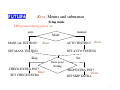
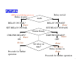
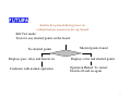
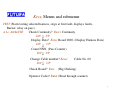
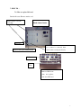
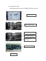
USER’S MANUAL(ver4.4)
OF
CABLE HARNESS TESTER
MODEL PHTM320 / PHTM640 / PHTM960
BY
FUTURA APSOL PVT. LTD.
1212/B/2, Apte Road,
Shivajinagar,
PUNE 411 004.
TELE- FAX: 020- 2553 1832
E-MAIL: [email protected].
www.futuras.com
Software Version: PHTM_GEN_5.5 and PHTM_320_4k_2.5 (19/12/2012)
1
Cable Harness Tester Models
PHTM320 / PHTM640 / PHTM960
Packing List
1. Cable Harness Tester 1 no.
2. This User’s Manual 1 no.
3. Mains cord 1 no. similar to PC mains cord.
4. A pair of multimeter test probes for board check and continuity check.
5. “Learn” lock key for learning a harness.
6. Cable from tester to board / rig as per number of points or connectors.
7. Futura’s Serial Cable.
8. A CD containing DOS as well as windows based PC software for serial
communication with tester and other details.
9. Enter Serial Number of Tester……………
Important Note: Preserve the packing sent along with the tester which is specially
designed for protection of the tester during transportation. In case tester is to be
sent back to Futura, use the same packing.
2
INDEX
1. IMPORTANT NOTES
1.1. Safety notes.
1.2. Changes in Various versions.
2. INTRODUCTION.
2.1. Description of the system.
2.2. Specifications
2.3. Tester.
2.3.1 Testing Features.
2.3.2 General Features.
2.3.3 Harness Data (Circuit Data).
2.3.4 Input / Output cards (I/O cards).
2.3.5 Keyboard.
2.3.6 Rig.
3. INSPECTION AND INSTALLATION.
3.1. Unpacking the equipment.
3.2. Installation.
4. OPERATION.
4.1. Operating Instructions.
4.2. Setting tester to test: Key LRN.
4.3. Interfacing with PC.
4.4. Testing and Test Results.
4.4.1 Testing.
3
4.4.2 Error types and reporting.
4.5. Interfacing Printer.
4.6. Interfacing Relay output.
4.7. Buzzer.
4.8. Interfacing barcode scanner / reader.
4.9. Analysis.
5. Discription of menus and user general instructions:
5.1 Power on learn menus:
5.2 Normal LRN menu:
5.3 Analyse Menu:
6. TROUBLESHOOTING.
6.1 On power on there is no display.
6.2 Display is “NO CARDS”.
6.3 After passing a harness tester displays “Remove Cable”. Even after
removing cable, tester does not display “Put Cable”.
6.4 How to increase number of points i.e. capacity of tester.
6.5 Tester shows “no point” after selecting a cable number.
6.6 Tester remains in receiving mode even after transmitting data from PC.
6.7 Erratic behavior of tester. Suddenly displays a point number which is not in
the circuit. Suddenly shows any error. Displays “no card”. etc.
6.8 After pressing ‘Test’ key, tester displays ‘Receiving’ and ‘hangs’:
7. HOW TO …
7.1 How to replace I/O card.
7.2 How to add I/O card.
7.3 How to Press / Replace Memory IC, replace program EPROM.
4
8. BASICS OF TROUBLE FREE OPERATION: (PROPER USE OF
TESTER).
9. RIG (BOARD) WIRING FOR FUTURA’S CABLE HARNESS TESTER
MODEL.
10. CALIBRATION OF FUTURA’S CABLE HARNESS TESTER MODEL
PHTM320.
11. OTHER CABLE HARNESS RELATED PRODUCTS
10.1 Harness Assembly Aid / Tester (HAA64).
10.2 One To One Continuity Tester with Parts Counter (CT121).
12. FUTURA’S PROFILE.
5
1: IMPORTANT NOTES:
1.1: Safety notes:
Safety Notes! Please read before putting the system into operation!
This system has been checked for safe and correct functioning before being
shipped. In order to keep this safety, the user has to pay attention to the
corresponding notes and advice of the operating manual.
# Before connecting test samples to the instrument, check for strictly
separation of the sample from power!
Any connection of the test sample to power can be dangerous for the
operator and can damage electronics.
# Before connecting test samples to the instrument, check for static charges of
the test sample, fixtures and operator which are to be eliminated. Otherwise
the test electronics can be damaged.
# Any external continuity meter like buzzer, bulb or multimeter should be
strictly avoided. Use of these will damage the test electronic.
# While changing the board; removal and fitting of D type connectors on the
back side of the tester or centronics connector on the board should be done with
utmost care. These connectors are polarised and hence should not be inserted in
wrong direction. There is a tendency to push the connector hard in the tester
even if polarisation is incorrect. Pushing might damage the connectors on I/O
cards or on the board of the tester.
# Check proper earthing at the power supply input of the Cable
Harness Tester.
Warranty void if equipment is opened by unauthorized person.
6
1.1 : Changes in this versions:
PHTM_GEN_3.0
1) Label data size has been increased to 4k (4096 bytes).
2) Facility to scan two operator codes.
3) On label operator codes can be printed by variables @B & @C.
PHTM_GEN_4.4
1) Provision for second relay is made in software.
2) If Hardware for second relay is present in the tester then second relay can be used.
3) First relay can be set as relay on pass or relay on fail as per the requirements.
4) But Second relay will be compulsory on after harness pass.
PHTM_GEN_4.6
1) New variable i.e. @U is added for label printing
@U followed by two characters will represents single byte hex value.
For ex @UAA i.e. OxAA.
At every @U, following value will be sent to the printer port.
I.e. in above example hex AA will be sent to port.
2) At every harness fail if relay on fail setting is enabled then harness name will be sent
On the serial port by default serial settings.
PHTM_GEN_4.7
1)
New modification in variable i.e. @U
For ex @UAA@1
For every date character hex value mentioned, will be sent before that character.
This modification will be applicable to PHTM label variables such as Time,
Serial number etc…for ex@U23@6000@6,@U@2.
PHTM_GEN_5.0 or PHTM_320_4K_2_0
1)
During harness testing if extra point settings is enabled and extra point is occurred
Then tester will once display error and declare harness is failed and goes for waiting
into testing of new cycle.
7
PHTM_GEN_5.5 or PHTM_320_4K_2_5
1)
@W is added in label printing variable. User details with maximum 16 bytes can be
added through serial port and will be printed via @W. On every power on if valid
user details are present then displayed on LCD.
8
Installation of PHTM960.
1. PHTM960 is similar to PHTM640 except
a.
Maximum number of I/O cards can be 15 i.e. 960 points.
b.
Keyboard, Learn lock key, Display, Buzzer, continuity and board check
are separated in a hand-held enclosure called MMI (Man-machine Interface)
terminals
unit.
2. Along with tester, find enclosed MMI unit and 26 way flat cable of length 1.5 m.
a.
Place the tester at a suitable location preferably under the table.
b.
Connect MMI unit to the tester using flat cable provided. At the back side of
MMI unit and tester, indicators for connections are provided.
3. Connect cables to board. Switch on supply to the tester. Rest of the connections are
similar as earlier.
To facilitate tracing of assembly and testing operators, facility to enter their codes and
printing them on label is added.
Two operator’s codes are to be entered.
Operator Code length should not be more than 8 characters.
On power off operator codes are not remembered. On every power on these have to be
entered / loaded.
Operator codes are entered through barcode scanner connected at the back side of tester to
‘serial’ port.
Communication parameters for operator barcode scanner are same as that for label
barcode scanner i.e. 2400 band; 8 bit data, 1start, 2stop bits and even parity.
Scanning is in ‘Analysis’ mode i.e. on pressing key ‘A’.
In label printing, @B prints first operator code and @C prints second operator’s code.
Operating sequence:
•
Label data has @B and @C at proper places where operator’s codes are to be printed.
•
Label data is transmitted to tester in the same way.
9
•
When operator code is to be changed, ‘A’ key is pressed. Display is ‘Check
Continuity’.
•
Down Arrow key displays ‘Operator codes?’
•
‘Enter’ accepts command and display is ‘Receiving code 1’.
•
First operator’s code is to be scanned by barcode scanner.
•
Display is ‘Receiving code 2’.
•
Second operator’s code is to be scanned by barcode scanner.
•
Both codes are displayed.
•
Tester displays ‘command?’
•
Tester is ready for any command.
10
2
: INTRODUCTION :
2.1: Description of the system:
Futura’s Cable Harness Tester (CHT), is designed to test Cable Harnesses,
Cable Looms, Cable Forms.
CHT locates interchanged connections, shorted
connections, open connection and extra points. CHT facilitates two stage testing of
harnesses.
CHT is a 16 bit Digital Signal Controller based stand alone unit; and
Hence testing speed has been enhanced as compared to older version. Time
taken to test depends on factors such as selected mode (auto / manual), extra point test,
number of points etc.
Minimum test system consists of Harness tester with mounting board / rig.
Complete test system consists of tester, a mounting rig, solid state Floppy, PC, printer or
stamping unit.
Harness tester is connected to the Rig (Jig) through “D” type connectors. Any
point on rig can be connected anywhere; meaning there is no “From” and “To” concept.
This simplifies the rig wiring to a great extent. This concept also facilitates in indirect
saving of space by accommodating different types of harnesses on the same mounting
rig. While designing the rig; care should be taken that all the end points or mountings of
all harnesses are taken on the board. Each mounting is connected to the tester. A harness
is mounted at particular mountings while learning the data as well as testing.
The harness to be tested is mounted on the rig and then tested through tester.
The errors can be seen on tester’s LCD display.
11
Learn Lock. Key provided to
be used to unlock. Learn can
be pressed after unlocking
only. Prevents unauthorised
changes in data.
16*1 LCD Display with
backlit.
Terminals for probes provided.
Red: Manual Continuity and
board check.
Black: Manual continuity.
Keyboard with 6
nos. dome type
keys.
Keys: Meaning
LRN: Learn: Load / change setup, harness data, date time, label data, barcoded number, harness name, two barcode
on flag etc.
TEST: Start testing of harness.
Enter: Accept command.
A: Analyse: continuity, board check, and display count, change cable number, display harness data.
∧ : Next command / number.
∨ : Previous command / number.
Cable Harness Tester PHTM320 Front Panel
Futura Apsol Pvt. Ltd., Pune 411 004, India.
DOC. NAME
Cable Harness Tester HTM320 front panel
DOC. NO.
HTM320FP
DIM IN
---------
MOD
DRN BY
SCALE
--------
GSR
DATE
18/4/03
PAGE
OF
MOD
MOD
12
I/O cards. Presently 2 nos.
Tester capacity 128 points.
Each card for 64 points.
Provision for 5 I/O cards in
PHTM320 and 10 in
PHTM640.
Mains power
supply Input
Mains
Switch.
Fuse, also an additional
fuse is given inside.
Serial RS232
15 pin D type
M. Points 1-15
Volume
Relay output.
Potential free.
230Vac, 5A.
25 pin D type
M. Points 16-39
25 pin D type
M. Points 40-64
speaker
Tone
To Printer
Cable Harness Tester PHTM320/640 Back Panel
Futura Apsol Pvt. Ltd., Pune 411 004, India.
DOC. NAME
Cable Harness Tester HTM320 / 640 back panel
DOC. NO.
HTM320BP
DIM IN
---------
MOD
DRN BY
SCALE
--------
GSR
DATE
18/4/03
MOD
MOD
PAGE
1
OF
1
13
2.2: Specifications:
Function: The Cable Harness Tester, tests a harness under test by checking each
point with each other point, compares the net-list with the stored net list and displays the
result. If the net lists match then displays “PASS” else displays the faults and the associated
number. Faults searched for and analysed and displayed are open point, open group, short
group, location interchange and extra point. Net-list is stored by learning a good harness or
from PC through serial. It also has a analyse function for continuity checking, board checking,
displaying pass count, changing cable number and displaying the learnt data.
•
Power supply.
* Supply Voltage: 230 V AC, 50 Hz. ±10%.
* Power consumption: Maximum 10 Watts.
* Fuse: 750 mA, normal.
•
Inputs.
* Test voltage: 5 V DC.
* Test current: In mill Amperes.
•
User Inputs: Keyboard input
* Dome type, dust proof keys with good tactile feedback.
* Number of operations: One million.
* Number of keys: 6 nos.
•
User Output: Display Output:
* Display used: 16 character LCD display with backlit.
* Buzzer, audio output on pass, with tone and volume control.
* Potential free Relay output up to 230V AC, 5A load.
* Piezo Buzzer, for continuity.
•
Interfaces: (PHTM320/PHTM640/PHTM960)
* Printer: Centronics parallel port for printers. Can print learnt data and
label
on Pass.
* PC: Standard RS232 serial at 2400 baud, no parity, 8 bit data, 1 start, 2
stop bits through a PC.
•
Environmental:
* Working temperature: 0° - 50° C.
•
Mechanical:
* Dimensions: 388 mm × 260 mm × 222 mm ± 2mm.
* Weight: Approximately 7.5 Kgs.
* Rust and scratch proof: Powder coated.
14
2.3: Tester: The tester is digital signal controller based unit. Refer Figure 1.2 for a view of
tester. It has facility to connect five add on I/O cards. One card is the minimum
configuration and it can test a harness with 64 points. By adding one card the capacity can
be increased by another 64 points; in the same manner maximum capacity can be 320 / 640
points with 5 / 10 cards. The tester stores the data into memory and compares it with the
tested data. If any error is found it reports through the 16 character LCD display. It also
recognizes the key pressed and functions accordingly.
PHTM320
Maximum number of points.
320
Max. 5 I/O cards
PHTM640
PHTM960
640
960
Max. 10 I/O cards Max. 15 I/O cards
In step of points
64
64
64
Maximum Number of harnesses stored in
EEPROM or battery backed RAM.
25
25
25
388(L) * 260
(D)* 222(H) ±2
500(L) * 260
(D)* 222(H) ±2
500(L) * 260
(D)* 222(H) ±2
Enclosure Size approx. in mm.
2.3.1: Testing Features:
• Tester will display the first occurred fault and will be scanning the harness
continuously and hence keeps on displaying the first occurred fault. Tests and displays
open point, open net, shorted net, interchange i.e. miss-location and extra point.
• By default tests ‘net by net’; starts with first net if found correct does not check
it again. ‘All Circuits’ mode can be selected on power on. All the nets tested in one pass,
if all are found correct, passes harness. For MSSL ‘All Circuits’ mode only.
• Testing can be Automatic (Auto) or manual. In auto mode, ‘TEST’ key is to be
pressed once. After passing a harness, displays “Remove Cable”. On removing harness
from board, displays “Put Cable”. Starts testing automatically when a harness is mounted.
In manual mode ‘TEST’ key is to be pressed for each testing. Mode selection is done once
by pressing ‘LRN’ key when power is switched on. In manual mode testing is faster.
Useful for harness with fewer points on testers with more points.
• Tests extra point which is not in circuit program / harness data but is on
harness. It can be skipped* by pressing ‘LRN’ key when power is switched on. To be set
once.
15
• Facilitates two stage testing. For example for fuse box. First stage complete
harness and second stage only fuses. Does not test for extra points in second stage.
• Switches a relay contact of 230 V AC, 5A capacity on for settable time (1 to 10
seconds) on for any application as stamp printing etc.
• Options available while placing order :
o
Small buzzer on each fault.
o
Instead of removing complete harness to start next test; start on
removing a point.
o
First stage testing twice and second once.
o
In second stage check only for open points, makes second stage
program writing as any two shorted points. Random data entry of
second stage.
2.3.2: General Features:
• Self test by pressing any key and switching on power without harness mounted
on the rig / board. Tests for any shorted points on the board and displays shorted points if
any. Else displays “Pass” and switches on relay and sounds buzzer.
• Based on digital signal controller based advanced technology which increases
speed, reliability and performance.
• Printing of labels on passing a harness on any parallel port printer. Label’s
text
is user programmable, maximum of 4096 characters with real-time date, time, week, month
and year. Option can be set on or *off after selecting Harness under Test, which is
remembered by tester.
• Read barcoded label on a harness before testing each harness, compare it with
loaded barcode and test only if both match. Option can be set on or off after selecting
Harness under Test, which is remembered by tester.
• Two barcode option is also available, read two different barcodes before
testing each harness, compare them with loaded barcodes and test only if both two match.
Option can be set on or *off through LRN menu.
• A harness named up to maximum 16 characters.
• Printing of harness data on a printer.
• Uploading harness data to PC.
• Check continuity of a harness manually.
16
• Check rig / board, as a part of periodic performance check.
• Download harness data, label data, harness name, barcode etc. from a PC
Using DOS as well as windows based software.
• Relay on time is settable through software. (1 to 10 sec).
2.3.3: Harness Data (Circuit Data):
Tester stores harness data in its memory which is retained even on power off.
Type of memory used is EEPROM. Earlier BBRAM (Battery Backed RAM) was used.
Harness data can be loaded either by self learning or downloaded from PC’s
serial RS232 port.
The tester can store data for twenty five harnesses. Harness data in Cable
number 0, cannot be stored on power off. Hence tester can test twenty-five fixed types of
harnesses and one general type of harness. The tester counts the number of points
‘learnt’ or loaded from PC and displays them to help learning as well as loading. Tester
also displays and compares the stored number of points and actual number of points in a
net list / programmes; when a cable number is selected. If they are not same the tester
displays error and disables “test” key. This facility confirms the correctness of data in
memory.
2.3.4: Input / Output cards (I/O cards):
I/O cards are connected to main controller unit, and controller controls them
all. Controller finds out the number of cards present and then displays results
accordingly. Add on card can be added at any time without changing hardware or
software. At one edge of I/O card; two D type 25 pin male connectors and one D type 15
pin male connector is provided. These are the points to be connected to rig. Tester has its
own power supply working on mains supply. The tester is a very handy unit and can be
shifted from rig to rig very easily.
2.3.5: Keyboard:
Keyboard is a sealed keyboard with six numbers dome type keys. It should be
pressed gently. More than one ‘Test’ keys are provided, as it is used frequently, life of
keyboard increases. Keyboard should never be pressed by nail.
17
2.3.6: Rig:
As the testing time reduces to one to five seconds; the harness mounting
time on the rig becomes very significant. All the harness points are to be mounted on
the rig. If connectors are used in a harness then time taken is very less.
We have developed some parts which take less efforts and time mount them on
rig.
All these points are to be brought to the D type connectors’ tester. The errors
give numbers as per D type connector’s connection. The same numbers are to be put on
rig for easy identification of the cable. Some other visual aids such as colored strips are
also on rig for ease of finding location on the rig.
18
3: INSPECTION AND INSTALLATION
3.1: Unpacking the equipment:
The equipment is packed in a corrugated box along with special packing to avoid transit
damages. Retain the packing material which is specific to your equipment. Following is the
list of items packed.
o
o
o
o
o
o
o
o
Cable Harness Tester 1 no.
This User’s Manual 1 no.
Mains cord 1 no. similar to PC mains cord.
A pair of multimeter test probes for board check and continuity check.
“Learn” lock key for learning a harness.
Cable from tester to board / rig as per number of points or connectors.
Serial Cable with models PHTM320 PLUS and PHTM640.
A CD containing DOS as well as windows based PC software for serial
communication with tester and other details.
Check for major damages in transport; such as removal of certain parts, bends, dents
etc. and inform FUTURA accordingly.
3.2: Installation:
Connect the tester with your rig as per stickers provided on rig as well as the controller.
Connect ‘D’ type connectors at proper positions such as CON 1. CON 2. etc. The number and
connectors will depend on the number and points.
Fix the “D” type connectors using small flat head screw driver.
Connect
mains
cord in
socket
provided on tester and switch on the
tester.
19
4: OPERATION
4.1: Operating Instructions:
Key Definitions:
Key operations are as follows.
For any wrong key pressed; message “CHEK KEY” will be displayed.
Key “LRN”
: Learn from mounted harness.
Key “TEST”
: Test mounted harness and show results.
Key “A”
: Analyse; for analysis.
Key “ ∆ ”
: Next selection / command / menu / number.
Key “ ∇ ”
: Previous selection / command / menu / number.
Key “ ↵ ”
: Enter; accept the selection / command / menu / number.
Refer figure for graphic representation of keys and menus and submenus.
20
Keys, Menus and submenus
Setup mode
LRN pressed during power on.
auto
manual
Mode
MANUAL TESTING?
AUTO TESTING?
Enter
SET MANL TESTING
Enter
SET AUTO TESTING
Skip
Set
Extra point
CHECK EXTRA PNT?
Enter
SET CHECK EXTRA
testing
SKIP EXTRA PNT?
Enter
SET SKIP EXTRA
21
LRN pressed during power on.
Relay on pass
Relay on fail
mode
RELAY ON FAIL?
Enter
SET RELAY ON FAIL
RELAY ON PASS?
Enter
SET REALY ON PASS
Printer Ready
CHK PRN READY?
Enter
ON
No key
Proceeds for further
operation
SKIP PRN READY?
Enter
OFF
Set relay on
time?
Enter
Up or Down
Relay on time xx
Enter
Proceeds for further operation
22
Analyse key pressed during power on
without harness mounted on the rig / board.
Self Test mode:
Tests for any shorted points on the board.
No shorted points
Shorted points found
Displays pass, relay and buzzer on.
Displays error and shorted points.
Continues with normal operation.
Operation Halted. To restart,
Switch off and on again.
23
Power on Page 1
Keys, Menus and submenus
Power On
FUTURA VER XX
Cards xx
All Circuits? Enter Set All Circuits.
Cable No. 00
DN
UP
Cable Number increments / decrements upto maximum / minimum. If
Harness Name is stored, displays name instead of Cable No.
Enter
No point , if empty memory. Compares actual number of points and stored
ones.
If match found, Points nnnn, number of points in memory for selected cable
number. Else Points Error.
24
Power on Page 2
No of stages x
No key
Change no of stages?
Enter
No of stages x
Up /Down
Enter
Clear Count @5 Seconds
Enter
Count Cleared
25
Label printing off
Print Label? @5 Seconds
Enter
Print Label on
Label Printing on
Off Print Label? @5 Seconds
Enter
Print Label off
Clear serial no?
Enter
Cleared
26
Power on Page 3
Barcode matching off
Barcode Matching on
Match Barcode? @5 Seconds
Bar Reader on
Enter
Bar Reader on
Command?
All required settings are over and ready to accept
command like test or learn or analyse.
27
LRN
Test Data?
2 Bar on
Enter Board to Data? Enter Learn? Enter Learning.
UP
2 Bar
off
Set 2 Bar On? Reset 2 Bar On?
Enter
Enter
2 Bar on
2 Bar off
DN UP
Label Data?
DN UP
Set Date –Time?
DN UP
Read Barcode?
DN
PC To Hrn Data Enter Receiving.
UP
DN
Hrn Data To Printer Enter Sending
DN
UP
Hrn Data To PC Enter Sending
Enter
Receiving.
Enter
Receiving.
28
2 Bar on
2 Bar off
Enter
Receiving Bar 1
Receiving.
Receiving Bar 2
DN
UP
Disable Barcode Enter Bar Reader Off.
DN
UP
Harness Name Enter Receiving.
Test starts testing selected harness.
29
Keys, Menus and submenus
TEST (Starts testing selected harness, stops at first fault, displays faults,
Buzzer, relay on pass.)
A I.e. ANALYSE
Check Continuity? Enter Continuity.
DN
UP
Display Data? Enter Board 0000. (Display Harness Data)
DN
UP
Count NNN. (Pass Counter).
DN UP
Change Cable number? Enter
DN
UP
Check Board? Ente
Cable No. 00
(Rig Cheking).
Operator Codes? Enter (Read through scanner)
30
4.2: Setting tester to test: Key LRN:
Learn Lock key position:
For ‘LRN’ key operation, tester checks for key switch on ‘Learn’ position.
For any other key operation, tester checks for key switch not on ‘Learn’ position. If it is,
then displays “Key lock on learn” and then ‘command’.
Sequence of operation should be: Key switch on ‘Learn’. Press ‘LRN’ key. Display is
‘TEST DATA’. Bring back key switch on ‘LOCK’ position. Press other keys.
Key switch is put on LEARN to learn or change the data. On pressing key
“LRN”, display will be “TEST DATA?” meaning “test data?” By pressing “∆” keys
displays will be
“SET OR RESET TWO BAR ON?” “LABEL DATA?”, “DATE-
TIME?”, “READ BARCODE?”, “DISABLE BARCODE?”, “HARNESS NAME?”
To accept test data command, press “ ↵ ”. Accepting test data means now test
data can be learnt from the board as or data can be received from a file in PC, or data can
be printed on a standard centronics printer or data can be transmitted to PC for storage.
Initially display will be “BOARD TO DATA?” meaning “board to data?” Press “ ∆ ” for
next commands and the displays will be “PC TO HRN DATA?” meaning “PC to data?”,
“DATA TO PRINTER?” meaning “data to printer?”, “HRN DATA TO PC?” meaning
“data to PC?” Same commands can displayed by pressing “ ∇ ” in reverse order. A
command is accepted by pressing “ ↵ ” key.
Board to data command will ask “LEARN?” To learn the harness data, put a
known good harness on the rig. Press “↵” to accept the learn command. Now display will
be “LEARNING POINTS nnnn”. Number of points learnt is nnnn. Hence if nnnn is less
than the actual number of points; points are missing due to some reason. After that
“COMMAND” will be displayed and tester will come in to idle position.
PC to data will load a data from file on PC to the selected harness number
through serial cable. Press “ ↵ ” to accept the command and now the display will be
“RECEIVING” meaning receiving. For this ensure using correct port COM1, correct cable
given with the tester, correct software on PC. More details are in the following sections.
Run programme in DOS mode on PC where it will ask for filename. Give the filename and
press enter. Data being transmitted will be displayed on the PC screen and after receiving
31
the data, tester will be ready to accept any command. Data can be verified by using display
data mode. Windows based programme also can be used.
If two stage data is transmitted from PC to tester, 2 stage testing is automatically set and
need not be set through keyboard. It will be set as per data transmitted from PC. If 2 stages
are on and a cable number is selected, tester displays no points in second stage also.
If two stage data is transmitted from PC to tester, 2 stage testing is automatically set and
need not be set through keyboard.
If label printing is on for a cable number, serial number can be cleared and made to print
from ‘000001’ for regular and ‘001’ for KIML. Tester asks “CLEAR SERIAL NO?” if
‘ENTER’ is pressed, serial number is cleared and display is “CLEARED”.
Data to printer will print the net list or stored data for selected harness number on
a standard printer which is used with PC. Same cable can be used to connect printer to the
tester where printer connector is marked.
Data to PC will transmit the data for selected harness number to PC through
serial port. Serial cable should be connected from PC to tester. Before pressing “ ↵ ”, on
tester, run program receive.exe on PC in DOS mode. Enter the non-existing filename to
store the data. PC will display the received data and store it in the file.
4.3: Interfacing with PC:
To load harness data, label data, date, barcode, harness name etc. PC has to be
interfaced with tester. Harness data can be transferred from tester to PC.
Load software from floppy or CD provided with tester. DOS based programs are
trans1_1.exe or tmssl.exe to transmit from PC to tester and receive.exe from tester to PC.
Windows based program is TCHT. It has to be installed on PC with minimum Windows
95 as operating system using setup.exe. This will create futura as group. TCHT version
1.01 is executed as any other windows program. Selection of correct communication port
(com port) is important.
Connect PC to tester using serial cable provided with the tester. The Y end i.e.
end with 9 pin and 25 pin connectors is the PC end and other 25 pin connector end is the
tester end. Y end is connected to a COM port on PC.
32
To load from PC to tester, a file has to be created. For harness data filename
extension required is .hrn, and for others extension required is .lbl. This can be generated
by using any text editor. EDD.EXE is one editor in the CD. Others like edit, notepad can
be used with care that file should be non document pure test file and it should have proper
extension.
Set tester in appropriate receiving mode. For DOS based execution, run
trans1_1.exe or tmssl.exe program in DOS mode. Where it will ask for filename. Give the
filename and press enter. Data being transmitted will be displayed on the PC screen and
after receiving the data, tester will be ready to accept any command. Data can be verified
by using display data mode. After receiving a label data, if printer is connected, tester will
print one label to verify. For windows based execution, TCHT will ask to select task and
then to select file. For harness data only .hrn files will be displayed and for others only .lbl
will be displayed. TCHT can also be used to create and edit .hrn as well as .lbl files.
33
Details of TCHT screen and sample files are as follows.
Select Task here
Sample files
Harness Data:
FILE EXTENSION SHOULD BE .HRN
THIS IS DUMMY DATA FOR A HARNESS.
NOTE:
HASH CHARACTER AT THE START AND END.
FIRST LINE IS NUMBER OF POINTS.
EACH POINT IS SEPARATED BY A SPACE.
NEXT LINE STARTS ONLY FOR NEW NET / CIRCUIT.
NO SPECIAL CHARACTER HERE.
IN A NET / CIRCUIT POINTS IN ASCENDING (SMALL TO BIG) ORDER.
ALL STARTING POINTS OF NETS / CIRCUITS IN ASCENDING ORDER.
#
35
1 6 77 90
2 4 5 89 91 120 190 211 234 256 278 280 290 300 540 555 600 601 602 623
3 50
78
9 10
11 23
13 15 56
#
This is second stage
#
34
8
1 2 6 50 77 90
39
#
Date Time:
FILE EXTENSION SHOULD BE .LBL
dd = date in 2 digits
mm = month in 2 digits
yy = year in 2 digits
hr = time hours in 24 hours format in 2 digits
mn = minutes in 2 digits
ss = seconds in 2 digits
HASH CHARACTER AT THE START AND END.
For Example On date 3 rd January 2000 and time afternoon 3:07:09;
String will be "030100150709"
For 2000 and onwards enter year in two digits only. Tester will
print year in four digits.
ddmmyyhhmnss
#030100150709#
Label Data:
EXAMPLE OF LABEL DATA.
NOTE
EXTENSION OF FILE SHOULD BE .LBL
BLANK LINE WILL BE PRINTED AS BLANK LINE.
AT @1 DATE WILL BE PRINTED.
AT @2 TIME WILL BE PRINTED.
AT @3 WEEK WILL BE PRINTED.
AT @4 MONTH WILL BE PRINTED.
AT @ 5 YEAR WILL BE PRINTED.
#
ITEM 01234
Futura
Time @2
Date @1
Year @5
Week @3
Month @4
Pass.
#
35
Barcode:
EXAMPLE OF BAR CODE.
THIS WILL BE COMPARED WITH SCANNED LABEL
NOTE
EXTENSION OF FILE SHOULD BE .LBL
START AND END WITH #
NAME CAN BE OF MAXIMUM 32 CHARACTERS
#
SAMPLE BAR LABEL
#
Harness Name:
EXAMPLE OF HARNESS NAME.
NOTE
EXTENSION OF FILE SHOULD BE .LBL
START AND END WITH #
NAME CAN BE OF MAXIMUM 16 CHARACTERS
#
SAMPLENAME
#
General points to remember for PC connectivity:
• For DOS based execution, files required on the drive are trans1_1.exe,
receive.exe, transmit. at. Copy all these files from the floppy ro CD provided to the PC.
• Data to be entered should be in non-document ASCII text mode using any editor
/ word processor.
• Start the data entry by a “#” character and end also by a “#” character. Any
matter before and after # will be considered as comments and can be used to write details of
harness.
• Always use correct COM serial port. By default serial port chosen is COM2. If
it is to be changed then open file transmit. At in an editor and last line which stands for com
port, 0 for COM1 and 1 for COM2. Change as per requirement and save in text mode only.
Do not modify any other data as these are the settings for serial communication.
• Always put the receiving item in receive mode first and then press “ENTER” to
transmit data.
• Connect the cable correctly as marked on cable.
Harness Data:
• Harness Data files should have extension “FILENAME.HRN”.
36
• First number should be number of points in the following harness data. If this
number and actual number of points do not match then tester gives error.
• Data is to be entered net by net, each net separated by a carriage return and line
feed i.e. press “ENTER” after every net only. End the data with“#” on the last line.
• Each point is separated by a space i.e. type space between each points.
• Any other character will not be recognised by tester.
Label Data, date / time, barcode, harness name etc. :
• Files should have extension “FILENAME.LBL”.
• Label Data can be an edited file or a pure ASCII file generated by a label
printing software. Preferably file size should be less than 200 bytes for each harness.
4.4: Testing and Test Results
4.4.1: Testing:
Press “TEST” key and wait till display “PUT CABLE” after that mount the harness to be
tested on the rig. The display will be “PASS nnnn” with audible beep sound for good
harness along with the count or directly errors (details in following section) will be
displayed for faulty harness. For a faulty harness; the tester will stop at first occurred fault
and test the same harness repeatedly and keep on displaying the same fault. It proceeds
only when the fault is removed. The tester will pass the harness only if it finds correct
harness as per selected test mode, “circuit by circuit” or “all circuits”.
When a harness is passed; in auto mode of testing, tester displays “REMOVE
CABLE”; meaning remove cable / harness from the rig. Tester will keep on checking if
the harness is removed completely. When harness is removed completely, the display will
be “PUT CABLE” i.e. indicating that there is no harness on the board and operator should
mount harness. Now the harness is to be mounted. Once tester finds a circuit mounted on
rig, it starts testing the harness and displaying first occurred fault. Hence test key is
required to be pressed only once to start the test. Now only the next harness is to be
mounted. To leave test mode Analyse‘A’ key can be pressed. If a harness name is entered
for that cable number, tester will display name in place of “cable”.
When a harness is passed in manual mode, tester keeps displaying “PASS” and
next test starts only after pressing test key.
37
Two stage testing: While testing, selected cable number program, is taken as
stage 1 and next cable number is taken as stage number 2. Tester checks for complete
correctness of harness in stage 1 if correct gives a small beep along with display “PASS 1”
meaning stage 1 passed. Then immediately starts checking for stage 2. While testing stage
2, tester only checks correct connectivity of program. It does not check for extra points.
Displays faults in the harness as per stage 2 program. When stage 2 also found correct,
first a small beep and “PASS 2” will be displayed then a long beep and “PASS XXX”
where XXX is the pass count for selected cable number. Now display will be “REMOVE
CABLE” and “PUT CABLE” as usual.
On “PASS”, a no potential relay contact of capacity 230V, 5 Amperes is
provided. The contact is on for selected time when a harness is PASSED. This can be used
to activate stamping unit or a label printer can be connected to print necessary labels by
switching on the option. A ringing buzzer on PASS is provided with volume as well as
tone control, to identify PASS signal. Volume and tone control can be adjusted using a
small screw driver from the back side of the tester.
“NO POINT” will be displayed if “TEST” key is pressed without data in the
memory of the selected harness number. While viewing the errors; user can test harness
again by pressing “TEST” key.
‘Test’ key operation. : In ‘Auto’ mode of operation, once in ‘Test’ mode, ‘Test’ key pressed
again will not be acknowledged. Only A key will be acknowledged
. In ‘manual’ mode for every test, ‘Test’ key is to be pressed.
VIMP: Key lock should be on ‘Lock’ while testing.
4.4.2: Error types and reporting:
Tester will display the first occurred error and will be scanning the harness
continuously and hence keeps on displaying the first occurred error. Tester can analyse
and report four types of errors as follows,
Open point: “OPEN PNT xxxx”:
If a point ‘xxxx’ is completely open. look at point xxxx.
Interchange: “LOCN xxxx yyyy”. :
If location of a point ‘xxxx’ is wrong or interchanged and is fitted to point ‘yyyy’.
38
Interchange: “LOCN xxx1 yyy1”, “OR”, “LOCN xxx2 yyy2”:
If interchange has occurred between two nets of two points each, tester cannot
locate exact interchanged point. It displays both possible interchanges.
Open group: “OPEN xxxx yyyy”.
In case of two point net from ‘xxxx’ to ‘yyyy’ or if some wires with point ‘yyyy’
from a circuit starting with point ‘xxxx’ get disconnected. Check only for “yyyy”.
Short group “SHORT xxxx yyyy” etc.:
If a circuit / net with first point ‘xxx’ get shorted with a circuit / net with first
point ‘yyyy’.
Extra point “EXTRA XXXX”.
If a point is not in the net list but it is connected to tester.
4.5: Interfacing Printer:
• A standard centronics port on DB25 F i.e. 25 pin D type female connector is
provided. It can be connected to any standard centronics printer available such as dot
matrix, ink jet, laser or bar code printers.
• Label printing is added to print a label on every passed harness. Data to be
printed on every pass can be different for each cable number, 25 different data can be
stored in tester’s memory. For each cable type 1024 bytes are reserved for label data.
• A complete label can be printed or if standard label is pre-printed then only
variable data can be printed.
• Tester can print variables viz. Date, time, week, month and year of testing. To
print these in label data, at the place where date is to be printed, “@ 1” should be placed
and for time “@2” is to be placed etc.
• To print special characters or bar codes, first of all printer has to be finalized.
Label or bar code printers accompany label printing software which generates an ASCII
file to be sent to printer for printing required data. Same file can be used by a little
modifications such as adding “#” characters at the start as well as end of the data and
adding character @ followed by required number, at required places for printing date and
time.
39
•
In Printing of labels, Following are special characters to be used.
@1: Date, Complete date in dd/mm/yy format
@2: Time (hr: mm:ss)
@3: Week
@4: Month
@5 : Year
@6---@6: Serial number, numbers between @6--@6 indicate serial no size.
Maximum serial no size allowed is 9.
Foe ex.@600001@6,5 (00001) digit serial no is initialized.
* special case: @6000000 (only six digits) allowed for making compatible with old HTM.
For entering serial number, enter 2 nos. less than the first label as it prints sample label.
@7: Repeated serial number
@8: Date.
@9: Not applicable.
@A: Not Applicable.
@B: Operator Code1.
@C: Operator code 2.
If label printing option is selected and printer is not connected or is offline, display will be
“printer not ready”.
4.6: Interfacing Relay output:
A potential free relay output with a capacity of 230V AC, 5A is provided on a
terminal strip on the back panel. This contact will be change over on every harness passed
for settable time.(1 to 16 seconds)
It can be used to glow a lamp or for hot stamping or for activating a pneumatic
circuit or for activating a solenoid. For inductive loads, use of snubber circuit will prevent
tester from malfunctioning.
P i.e. Pole and NO i.e. Normally Open get connected when relay is on and pole
and NC i.e. normally Closed get open when relay is on.
40
4.7: Buzzer:
On passing a harness a ringing buzzer sounds for @ 3 seconds. Buzzer’s tone and
volume can be controlled from presets at the back side.
Different tones can differentiate passed harnesses and to avoid confusion.
4.8: Interfacing barcode scanner / reader.
Function: To read bar code on each harness before testing; using a bar code
reader is added. A tester match this bar code with the stored one and continues if both match
else displays “BARCODE ERROR”. This ensures testing correct harness as selected program.
A barcode scanner with serial port can be connected to tester. Serial scanner
needs external power supply voltage. Tester cannot supply power to barcode scanner.
Settings of a bar code reader are 2400 band; 8 bit data, 1start, 2stop bits and
even parity. And data can be 1 to 16 digits in length and only bar code in ASCII without any
other characters.
Testing should start without harness. During testing, when test key is
pressed; display will be ‘RECEIVING’ and waits for bar code data on RS232. Once received
compares with stored bar codes. If a match is found then continues testing; if codes do not
match then displays ‘bar error’.
When harness is tested and passed, display will be “REMOVE CABLE”. Bar
code should be scanned only when message is “Receiving”. Tester will not recognise if
scanned otherwise.
Label printing option if required, should be made on and remains on even if
program is changed through bar code reader until it is switched off.
If tester is in two barcode on mode then before testing it will scan two different
barcodes and enters in to testing only when both barcodes matches.
4.9: Analysis:
In analysis mode i.e. key “A” available functions are “CHEK CONTINUITY?” to
check continuity, “CHECK BOARD” to check board, “COUNT XXX” to display pass
count, “CHANGE CABLE NO?” to change cable number, and “DSP DAT?” to display
data, “OPERAOTR CODES?” to receive operator codes. “∆
∆” and “∇
∇” keys facilitate
selection of functions and on pressing “ ↵ ” key accepts that function. In case of count
display “ ↵ ” key is not required.
41
To manually check continuity in a harness, use this mode. In continuity checking
mode, display is “CONTINUITY”, the red and black terminals on the front panel are to be
used as two probe points. Please refer the attached front panel diagram. A pair of probes is
also provided. Continuity checking can be stopped by pressing any key.
To check rig / board or cable from tester to board or I/O card, use this mode. In
check board mode, the display will be “BOARD 0000”. The red terminal on the front
panel is to be used as a probe point. Please refer the attached front panel diagram. A pair
of probes is also provided. As soon as the probe is touched to a point on the board; display
will be “BOARD XXXX”; where XXXX means the corresponding I/O number. Board
checking can be stopped by pressing any key.
In change cable mode cable number can be changed. In this mode display will be
“CABLE NUMBER XX” where XX stands for current selected cable number. It can be
changed using “∆
∆” and “ ∇ ” keys and “ ↵ ” key accepts the cable number. In 2 stage
testing if one stage is complete, and second stage is not complete, this option is not
available.
In display data mode, harness data is displayed. First of all “POINTS nnnn” will
be displayed. Where nnnn are the number of points for the selected cable number. The
learnt data or, net list as it is called can be displayed in this mode. Points will be displayed
one after another with a fixed delay. At a time one point is displayed. When the net is
complete; “NEW NET” is displayed. After end of data “OVER” will be displayed. And
tester will return to command mode.
In receive operator codes mode tester is ready for reception of 2 operator codes
from barcode scanner.
After scanning operator codes it will be saved in temporary
memory and can be printed on label by @B & @C. After power off operator codes will
be vanished.
42
5: Description of menus and user general instructions.
5.1 Power on learn menus (After pressing LRN key on power on and key position on
LRN)
Auto testing: Testing will be done in auto mode.
Manual testing: Testing will be done in manual mode.
Skip Extra pnt: Disable extra point testing at harness testing.
Check extra pnt: Enable extra point at harness testing.
Relay on pas: Enable relay after passing harness up to settable time.
Relay on fail: Disable relay after passing harness.
Set Relay on time: Relay on time can be set between 1 to 10 seconds in this mode
by up or down key. This time will be saved in the memory so that can be retrieved
after power off.
5.2 Normal LRN menu:
* To enter in to this menu before pressing LRN button, key position must be on
Learn position, if not entry will be disabled.
* While pressing any other key than LRN key ensure that key position should not
be on LRN position otherwise operation will be failed with display “KEY LOCK
ON LERAN”.
•
Test Data: Processing of test data.
•
Label Data: Receive label data from pc.
•
Harness Name: Receive Harness name from pc.
•
Read Barcode: Save barcode from pc.
•
Set Date and Time: Receive date and time from pc.
•
Set or Reset 2 Barcode on: Enable or Disable 2 barcode mode.
5.3 Analyse Menu:
•
Check Continuity: Checks continuity in this mode.( use probes )
•
Display Data: Displays harness data present at that cable number.
43
•
Change cable number: Navigates through cable number 1-25, and selects
it.
•
Pass count: Displays Pass count.
•
Board check: Checks board at every point.
•
Operator codes : Facility to scan two operator codes.
44
6: TROUBLESHOOTING:
Futura Apsol Pvt. Ltd. is not responsible for any modifications
done in tester circuit without consultation with Futura or by an
unauthorized person.
General: CHT tester is thoroughly tested before leaving the factory. It is
recommended that in case CHT fails, the user should follow the troubleshooting guide
before contacting FUTURA. Proper use will prevent CHT from failures.
Frequently Asked Questions: FAQs:
6.1: On power on there is no display:
• Check for loose power supply cable i.e. mains cord, input mains plug as well
as socket.
• Check Fuse (750mA, normal). If burnt replace with spare one available in the
fuse holder.
6.2: Display is “NO CARDS”:
• Switch off the supply, press the I/O card/s. Switch on the supply.
• switch off the power supply, remove I/O card/s and clean the edge
connector on I/O card/s using trichloroethylene or CTC. Insert the I/O
card/s properly and check the tester.
6.3: After passing a harness tester displays “Remove Cable”. Even after removing
cable, tester does not display “Put Cable”.
•
It means that tester finds some points internally shorted even if harness is
removed.
•
Conduct self test after removing harness from the board. Tester will
display shorted points. Check these points on the board.
•
If problem persists, separate board from tester at board end and conduct
self test. Check for shorted points from tester to board.
•
If problem persists, remove cable from back side of the tester and conduct
self test. Check for shorted points and replace appropriate I/O card.
Refer 5.10.1: How to replace I/O card.
45
6.4: How to increase number of points i.e. capacity of tester?
•
Capacity of PHTM320 is maximum 320 points and PHTM640 is
maximum640 points.
•
If tester has less number of I/O cards than its maximum capacity, it can be
increased by adding an I/O card in the next available slot.
Refer section 5.10.2: How to add I/O card.
6.5: Tester shows “no point” after selecting a cable number. :
•
Press memory IC (24c512) in tester, in which all programs are stored.
6.6: Tester remains in receiving mode even after transmitting data from PC.
•
Check connection of serial cable, Y end to PC and single end to tester.
•
Replace serial cable.
•
Check communication port number selected and connected and working.
(COM port) com1 / com2.)
6.7: Erratic behavior of tester. Suddenly displays appoint number which is not in
the circuit. Suddenly shows any error. Displays “no card”. etc.:
•
Check for proper earthing at the power supply input point of tester. It
should be proper voltage in L and N and similar voltage in L and earth and
less than @ 8 V in N and earth.
6.8: After pressing ‘Test’ key, tester displays ‘Receiving’ and ‘hangs’:
•
It means barcode reader option is switched on. To switch off, press ‘LRN’,
‘up’ or ‘down’ till display is ‘disable barcode?’; Press ‘enter’, display will
be ‘bar reader off’.
6.9: After passing of harness, tester displays “No Points”or “Open xxxx” instead of
“Remove Cable”:
•
Chek no of stages selected for the respective cable number, if 2 stages are set
then make stages 1.
6.10: After passing of harness, tester remains “Pass xxx” instead of “Remove Cable”
•
Check mode of testing, if Manual mode is set, change it to Auto mode
Through power on learn key.
6.11: Tester is not getting powered.
• Check the condition of fuse, if found burnt then replace it with additional
fuse given with socket.
46
7: HOW TO …
7.1: How to replace I/O card.
Switch off tester. Remove mains cord.
Remove these 2 screws
near edge.
Back view of tester
I/O card
If it cannot be removed then
Remove this plate with I/O PCB
remove this second plate first by
PCB
Plate
Remove PCB from
plate and replace
with new PCB and
47
7.2: How to add I/O card.
Switch off tester. Remove mains cord.
Remove these 2 screws
near edge.
Back view of tester
Previous
I/O card
Remove this plate with I/O PCB. Remove these screws and remove covering
plate. Keep holding painted blocks from inside. Assemble new I/O card using
blocks and screws provided.
I/O card
Take new I/O card and
assemble with removed plate in
the tester in the same way.
Plate
Insert card in the slot using guides provided in the tester with 15 pin connector at the top. Feel the
card fitting firmly in the connector.
Connect Mains cord and switch On tester.
Check all I/O points with board check.
48
7.3: Connections Of new CPU
Following photos indicate internal view of PHTM CPU and all its connections.
Front view of tester.
Here CPU PCB is located.
10 pin Connector from IO cards
FRC connector for Display
FRC connector from
motherboard
Program Module of CPU
CPU overview
49
8: BASICS OF TROUBLE FREE OPERATION: (PROPER USE OF TESTER)
The following basic procedures are essential for safe and trouble free
operation of the system.
•
Installation and operation of the tester or system according to the
directions in the manual.
•
Power supply: 230 V AC, 50 Hz. +/- 10% with proper earthing. Use of
CVT for power supply fluctuations.
•
Packing tester properly while shifting from one location to other.
•
Supporting cables connected to I/O cards at the back side of tester, so that
I/O cards are not pulled.
•
Fastening of all dust covers of connectors at I/O cards to hex nuts of I/O
cards.
•
Using proper tool to set tone and volume control.
•
Using key provided to unlock Leann’s lock and not using tools like screw
driver.
•
Using built in manual continuity checker for checking continuity of
harness only and not for any other purpose.
•
Using keyboard properly. Pressing single key at a time. Pressing keys
using fingers and not nails, tools etc. Taking care not to damage keyboard
physically.
50
9: RIG (BOARD) WIRING FOR FUTURA’S CABLE HARNESS TESTER MODEL
PHTM320.
As Future’s Cable harness tester does not have “from and to” concept for wiring
the board or rig; it is very easy and simple to wire a rig.
Refer to the attached figure for connector details. Each I/O card has three
connectors specified as 15 pin D type M, 25 pin D type M: 2 nos. For wiring the rig
required connectors are the opposite connectors. Hence for 64 points required connectors
are 15 pin D type F; 1 number and 25 pin D type F; 2 numbers. The I/O point’s number 1
to 64 is numbered as shown. The meaning is that if a terminal on harness is connected to
I/O point number 5 on card through rig then while showing fault or net list or board check
that point will be referred to as point number 5.
In Future’s PHTM320; each and every point acts as “from” or “to”. Hence to wire
the rig circuit of harness is not taken into consideration and any point can be connected
anywhere. While learning; the tester takes care of the circuit.
One most important point to consider is that each and every terminal on the
harness has to be connected to the tester through rig. Layout of harness on the rig, size of
the rig, position of tester etc. can be as per one’s convenience.
After wiring of the board; visual indications at each mounting point can be
pasted. The details such as wire color, wire number from the drawing, corresponding
number associated with tester (it should be prominent) etc. can be pasted. The final board
check can be done to ensure correct connections of rig to the tester. Now the complete
harness test system is ready.
The master harness is mounted properly. Cable number where the harness data is
to be stored is selected and the data is learnt. Learnt data is seen on display using analysis
and display data function and is noted down. First step is to confirm number of points as
expected. This data is the net list of the harness. The noted data is cross checked for
required data by checking wire color.
Now the test system is ready for testing harnesses.
51
Another advantage of PHTM320 is that since it does not have “from and to”
concept; one rig can be designed to mount different types of harnesses. For this purpose;
all the required harnesses are to be collected and a board is designed to have all the end
points of the harnesses. These are connected to the tester. Many points can be made
parallel by proper selection. Different templates for different harnesses can be made for
easy mounting. Each template has visual indications for mounting the harness. The only
important point is that while testing the harness has to be mounted in the same way as it is
mounted while testing. Different harness data is stored at different memory locations. This
data i.e. net list is noted down and cross checked before the testing starts. Now the test
system is ready to test multiple harnesses.
For testers with more than one card; the I/O points are above 64 i.e. in second
card points are 65 - 128, third card 129 - 192, fourth card 193 - 256, and fifth card 257 320. The sequence of points is same as that shown in figure i.e. for 1 - 64 points. Only that
number of in the tester is to be found then find the point number from 1-64 say ‘p’ and add
‘64 * (n-1)’ to ‘p’ and the addition gives exact point number.
This way Cable Harness Tester PHTM320 can be connected to the rig and fully
points are to be added as per number of cards present to get actual point. If point in ‘n’ th
card utilized.
52
Connection details for I/O card to 36 pin centronics connector
i.e cable wiring details from tester to board.
I/O Number
as displayed
on tester.
(use brd chk)
I/O card
Connector no.
1
2
3
4
5
6
7
8
9
10
11
12
13
14
15
16
17
18
19
20
21
22
23
24
25
26
27
28
29
30
31
32
33
34
35
36
1
1
1
1
1
1
1
1
1
1
1
1
1
1
1
2
2
2
2
2
2
2
2
2
2
2
2
2
2
2
2
2
2
2
2
2
Pin no. Printed
on connector
8
15
7
14
6
13
5
12
4
11
3
10
2
9
1
13
25
12
24
11
23
10
22
9
21
8
20
7
19
6
18
5
17
4
16
3
36 Centronics Connector connected
to cable (M), on board / Rig (F)
Connector
No.
1
1
1
1
1
1
1
1
1
1
1
1
1
1
1
1
1
1
1
1
1
1
1
1
1
1
1
1
1
1
1
1
2
2
2
2
Pin No. Printed on
connector
1
2
3
4
5
6
7
8
9
10
11
12
13
14
15
16
19
20
21
22
23
24
25
26
27
28
29
30
31
32
33
34
1
2
3
4
53
I/O Number
as displayed
on tester. (use
brd chk)
I/O card
Connector no.
37
38
39
40
41
42
43
44
45
46
47
48
49
50
51
52
53
54
55
56
57
58
59
60
61
62
63
64
2
2
2
3
3
3
3
3
3
3
3
3
3
3
3
3
3
3
3
3
3
3
3
3
3
3
3
3
Pin no. Printed
on connector
15
2
14
13
25
12
24
11
23
10
22
9
21
8
20
7
19
6
18
5
17
4
16
3
15
2
14
1
36 Centronics Connector connected to
cable (M), on board / Rig (F)
Connector
No.
2
2
2
2
2
2
2
2
2
2
2
2
2
2
2
2
2
2
2
2
2
2
2
2
2
2
2
2
Pin No. Printed on
connector
5
6
7
8
9
10
11
12
13
14
15
16
19
20
21
22
23
24
25
26
27
28
29
30
31
32
33
34
Above details can be used to repair, correct or to make a new cable from tester to
board / rig. It can also be used to add new mountings (points) to the board with centronics
connectors on board / rig.
Similar configuration is used for higher numbers.
54
10: CALIBRATION OF FUTURA’S CABLE HARNESS TESTER MODEL PHTM320.
Since the certification such as ISO, QS, IS etc. are important; the calibration of
the testing equipment is also important.
1: As the tester compares data or connections of a standard harness with the
connections of Harness under Test; calibration is not required.
2: PHTM320 does not measure any absolute quantity hence calibration is not
required.
3: To confirm functionality of the test system i.e. test equipment along with test
rig, following procedure can be repeated after fixed period say 3 months or 6 months.
A : To check the contents of memory ; “display data” in “analysis “ mode is
used and the data is confirmed against the data (net list) written down by hand after initial
“learning” procedure of the harness or printed data attached in user’s manual if the board
is supplied by Futura. It will be a good practice to file the master data for each harness.
Time taken will be @ 5 minutes for each harness type, Tools required are none.
B: To check functionality of the equipment and the board, “check board”
facility in “analysis” mode is used and every point on the board is checked. Time taken
will be @ 10 - 15 minutes, Tools required are test probes provided with the equipment.
55
11: OTHER CABLE HARNESS RELATED PRODUCTS:
11.1: Harness Assembly Aid / Tester (HAA64):
Function: Harness Assembly aid is a tool useful for harness assembly / sub assembly.
Basis of HAA64 is that harness assembly is done in steps. Each step involves picking up a part
either a crimped cable / cable assembly or a grommet etc. from a tray and inserting terminals in
housings at proper location i.e. points.
During assembly, in a step, HAA64 guides operator to pick parts from proper tray by
glowing corresponding LEDs. Then HAA64 glows LED at first point where terminal is to be
inserted and blinks LED at point where next terminal is to be inserted. Once correct insertion is
done, point’s LED stops blinking and HAA64 moves on to next point in the same step. If
insertion is wrong then HAA64 will keep displaying fault like open and short and will not go to
next step unless correct connection. Once a step is complete HAA64 will move on to next step.
An audio signal along with relay output and visual signal will be given out when all steps are
over. HAA64 will start assembly of new component only when old one is removed.
56
Each step is programmable for tray and points of choice. Complete system consists of
HAA64, a set of trays with LED at each tray along with numbers, a fixture with LED at each
point along with numbers.
Technical Specifications:
Power Supply: 230V ac +/- 10% AND or OR 12 V DC, 800 mA.
Number of programmable steps 99, with 48 number of trays and 64 number of points,
programmable by user, by ‘Learning’.
Test Parameters : 5V DC @ current in mA.
Tester I/Os : 37 pin D F, 2 nos. for points, 32 points in each. 37 pin D F connectors 4
numbers for 64 point LEDs, 16 in each. 37 pin D F connectors 3 numbers for tray LEDs, 16 in
each. Terminated at back side of tester.
User interface: 4 key touch pad sealed, keyboard. Facility to connect PC keyboard. 16×1,
large character LCD display with backlit. Output on Pass is Buzzer audio; Relay no potential
contact rating 230V, 5A, and a LED.
Operation: HAA64 has Three modes viz. ‘assembly’, ‘setup’ and ‘analyse’.
Assembly mode guides the operator through assembly.
In setup mode, component, selected component’s data, and its name can be
changed. In change data, data for one step can be edited or a complete new data can
be entered. Name of component can be changed through PC keyboard.
In analyse mode, data for selected component can be displayed, self test can be
carried out and fixture / rig / board can be checked.
Assembly is carried out as explained in function above.
Programming new data:
Programming of a new data needs completely wired fixtures and point numbers where
terminals will be inserted. Once new data is selected, data starts from step number 1. Step
number will be displayed on the left hand of display.
In any step First available tray’s LED will be on. Required tray LED can be made on
using ‘up’ and ‘down’ keys. Only unselected or available tray LEDs will be on. Once selected,
to programme the same ‘enter’ key is pressed. Now again first available tray’s LED will be on
for selection. Hence a step can have more than one trays. After completing selection of trays in
that step, ‘escape’ key will switch to learning circuit for the step.
57
Now first available point LED will be on. Selected point will be end A or starting point
of circuit. It can be selected by using ‘up’ and ‘down’ Once finalized, remaining terminals are
to be inserted at respective locations. As soon as terminals are inserted, corresponding LEDs
will be on. After insertion of complete circuit, ‘enter’ key will store circuit data in memory.
It completes programming of a step. Immediately tester will move on to next step. To
stop programming ‘escape’ key is pressed twice.
Editing a step asks to select a step to be edited and then same steps as programming a
step are to be followed.
Self Test : In self test all LEDs will glow one by one for visual inspection and tester
searches for all points open. If open then passes self test else asks to remove component.
‘Escape’ is used to change current mode to parent mode. Only while programming, it
changes from tray to points.
HAA64 is enclosed in a rugged enclosure for continuous use industrial environment.
58
11.2: One To One Continuity Tester with Parts Counter (CT121):
Function: One to One continuity tester is to test point to point continuity of a circuit.
Application can be a fixture with limit switches, a connector or a coupler with open ends. It does
not check midjoints. Tester can test for maximum of 48 (96) circuits/cables. Last circuit to be
tested is user programmable. Set up allows programming of last circuit, component name. Last
circuit can be stored for 25 different components. CT121 also has parts counter to count parts on
a harness using a limit switch probe. Numbers of parts are programmable for 25 different
harnesses along with harness name. Maximum parts counted are 99.
Technical Specifications:
Power Supply : 230V ac +/- 10% AND or OR 12 V DC, 800 mA.
One to One Tester : Number of circuits to be tested 48 circuits i.e. 96 points on one module /
card; expandable to 96 circuits using additional card. Last circuit to be tested, programmable by
user. Refer document for circuit connections.
Test Parameters : 5V DC @ current in mA.
Tester I/Os : 25 pin D RA F, PCB mountable connectors, 2 nos. for “from” 48 circuits and 2
nos. for “to” 48 circuits. Terminated at back side of tester.
Parts Counter : Maximum number of parts counted : 99 (Ninety Nine) Input from a probe
with limit switch using 9 pin D type ‘F’ connector at pin numbers 1 and 2.
User interface : 4 key touch pad sealed, keyboard. Facility to connect PC keyboard. 16×1,
large character LCD display with backlit. Output on Pass is Buzzer audio, Relay no potential
contact rating 230V, 5A, LED.
Operation : CT121 has two modes viz. ‘Setup’ and ‘Test’. In setup mode, test mode and
selected component’s database can be altered. Available test modes are ‘All Circuits’, ‘Circuit by
circuit’ and ‘parts counter’. In all circuits mode tester should find all correct connections in one
pass while in circuit by circuit, connection can be random and momentary. It is useful for fixtures
with limit switches and without locks. Parts counter helps in counting parts. Change Data
facilitates selecting a Component out of 25nos.,and changing last circuit to be tested and changing
name of component through PC keyboard. Last Circuit informs tester to test upto last circuit.
CT121 finds and displays faults such as open and short along with faulty circuit numbers.
On correct connections, sounds buzzer, changes relay state and glows LED for @3 seconds and asks
component to be removed. Testing starts again only when component is removed. CT121 is enclosed in
a rugged enclosure for continuous use industrial environment.
59
12 : FUTURA’S PROFILE :
Futura Apsol Pvt. Ltd.
Visit www.futuras.com for details.
Sr. No.
Futura's Products
1 Testers for cable / wiring harness
1.1 Cable Harness Tester, 320 points, with serial, parallel.
1.2 Cable Harness Tester, 640 points, with serial, parallel.
1.3 Cable Harness Tester, 960 points, with serial, parallel. And MMI unit
Cable Harness Tester for 1024 points with serial, parallel, CHT Enhancer
1.4 attached
1.5 Add on I/O card for 64 points
1.6 Testing Rig to mount harness
2
2.1
2.2
2.3
2.4
2.5
2.6
One to one continuity tester with parts counter
One to One continuity tester for 48 circuits
One to One continuity tester for 96 circuits
One to One continuity tester for 6 circuits
One to One continuity tester for 10 circuits
Clip Assembly Aid
One to One continuity tester for 32 circuits
3 Harness Assembly Aid
3.1 Harness Assembly Aid for 64 points and 48 trays
3.2 Harness Assembly Aid for 64 points and 48 trays with pull test
3.3 Harness Assembly Aid for 96 points and 96 trays with 10 pull test
4
4.1
4.2
4.3
Data Collectors / converters
Gauge Link.
RF to RS232 converter.
Solid State Floppy
5
5.1
5.2
5.3
5.4
5.5
5.6
5.7
5.8
5.9
Automatic Test Equipments / Systems for
Transformer cut / toroidal cores
12V DC fans
Relays*
Timers*
Capacitor discharge welds.*
Fuel gauge*
HT Coil*
Pick up coil.*
Cockpit / dashboard *
60
6
6.1
6.2
6.3
6.3.1
6.3.2
Switch Testing
Switch Harness tester (without load)
Combiswitch tester (switch test with load)
Switch test endurance
Programmable load / power supply.
Waveform Capture.
7
7.1
7.2
7.3
7.4
7.5
Computer Peripheral:
Printer sharer Auto 4*1
Printer sharer Auto 2*1
Printer data switch, manual 1*2
Printer data switch, manual 2*2
Printer data switch, manual 4*1
8
8.1
8.2
8.3
8.4
Electronic Scarecrow : EBU :
Electronic Scarecrow for animals
Electronic Scarecrow for birds
Electronic Scarecrow for animals and birds
Electronic Scarecrow deluxe
9
9.1
9.2
9.3
Tapeless Recorder
Music on Hold. TLR90
TLR90 with recording.*
Museum Guide.
10 Electrical Test System for Automobiles ETSA*
11 Automobile Regulator Calibrator
12 Electronic Shouter.
13 PC based Harness Assembly Training.
61


![User`s Manual [(ver2_0] Label Data Storage for Printing](http://vs1.manualzilla.com/store/data/005731436_1-9878257490003fe38f3b53735b78440c-150x150.png)


![User`s Manual [(LDSP_LCD_99_2)] Label Data](http://vs1.manualzilla.com/store/data/005846764_1-de86383eb41f3d06a08b51e5958ead91-150x150.png)