1
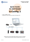
Assisting the automation
industry since 1986
User manual
for PC software
SimCorder Soft
•
•
Version: 3.0.0 or higher
Read the user manual carefully before starting to use the software.
Producer reserves the right to implement changes without prior notice.
15.03.2011
SimCorder_INSSXEN_v.1.02.004
User manual for PC software SimCorder Soft
CONTENTS
1. GENERAL CHARACTERISTICS................................................................................................................3
2. INSTALLATION STEP BY STEP................................................................................................................3
3. USING OF “SIMCORDER SOFT” PROGRAM........................................................................................10
3.1. APPLICATION STARTUP................................................................................................................12
3.1.1. Licence Information.................................................................................................................12
3.1.2. Main program interface...........................................................................................................13
3.2. “CURRENT MEASUREMENT” MENU.............................................................................................15
3.2.1. “Table” tab...............................................................................................................................15
3.2.2. “Graph” tab..............................................................................................................................17
3.2.3. “semiSCADA” tab....................................................................................................................21
3.2.4. “Device Info” tab......................................................................................................................22
3.3. “REPORTS” MENU..........................................................................................................................23
3.3.1. “Table” tab...............................................................................................................................23
3.3.2. “Graph” tab..............................................................................................................................25
3.4. “CONFIGURATION” MENU.............................................................................................................26
3.4.1. “Devices” tab...........................................................................................................................26
3.4.2. “Groups” tab ...........................................................................................................................31
3.4.3. “Alarms” tab.............................................................................................................................31
3.4.4. “Settings” tab...........................................................................................................................32
3.5. GROUP OPERATIONS....................................................................................................................33
3.6. SIGNALISATION OF SYSTEM ALARM STATES...........................................................................34
3.6.1. Defining of alarm states..........................................................................................................34
3.6.2. Defining of relations between device messages and alarm states........................................36
3.6.3. Defining of relations between alarm states and alarm devices..............................................37
3.6.4. Example configuration of alarm states signalisations.............................................................38
3.7. “SEMISCADA“ MODULE..................................................................................................................40
3.7.1. Description of semiSCADA interface......................................................................................40
3.7.2. Opening a configuration..........................................................................................................42
3.7.3. Creating a new configuration..................................................................................................42
3.7.4. Indicators.................................................................................................................................44
3.7.5. Shapes and descriptions.........................................................................................................52
3.7.6. Examples of configuration.......................................................................................................53
3.8. ALARM NOTIFICATIONS................................................................................................................57
3.8.1. GSM notification......................................................................................................................57
3.8.2. E-Mail notification....................................................................................................................58
3.9. APPLICATION CLOSING.................................................................................................................59
3.10. LIST OF ERRORS AND FAULT DIAGNOSTICS .........................................................................60
Explanation of symbols used in the manual:
i
2
- This symbol denotes especially important characteristics of the software working.
Read any information regarding this symbol carefully
User manual for PC software SimCorder Soft
1. GENERAL CHARACTERISTICS
The SimCorder Soft program enables the visualization, archiving and printing of
measurements (e.g. temperature, humidity, pressure). Work with network of units takes place
through an RS485 serial interface. Connecting a network of units to a serial port (RS 232) or
USB port of a PC is possible thanks to a converter (RS 485 to RS 232 or RS 485 to USB)
produced by SIMEX.
2. INSTALLATION STEP BY STEP
1. Install SimCorder Soft from included CD. SimCorder Soft is designed to Windows
operating system (Windows 98 or newer).
i
Install BASIC, ALARM or SERVER version of SimCorder Soft on the PC directly
connected to network of units. The TERMINAL version of SimCorder Soft allows
visualization (via internet) of devices working controlled directly by SERVER version
of SimCorder Soft. The SERVER and TERMINAL version are included in one
package named SimCorder Soft NETWORK.
The SimCorderSoft-v(NR)-install file is designed to install the SimCorder Soft
program (NR is a version number). The install file is locate in folder on CD delivered with
device.
During installation follow the directions provided by Installation wizard. The wizard
will create a folder on the computer’s hard drive, the program files will be placed in this
folder. The short cut to the program will be placed in a location specified by the user.
During installation, you may receive a system message instructs you, that installed driver
is unsigned ( Figure 2.1). This message applies to the driver of USB License Dongle
required to run the application with full capabilities. You shoud agree to the installation by
clicking on [Continue Anyway] or [Install this driver software anyway] depending on
your version of Windows. After connecting the USB License Dongle into a computer,
system will be able to automatically detect and install the appropriate drivers.
Figure 2.1. Message asking you to install USB License Dongle driver
on Windows XP (on the left) and Windows Vista / 7 (on the right)
Manual start-up of the program is done using the SimCorder.exe executable file.
3
User manual for PC software SimCorder Soft
2. Initial start-up of the application enables detection of all devices present in the network
(excluding TERMINAL version). The user is asked to perform installation and configuration
procedure for all detected devices.
Follow the guidelines in the windows displayed by the program. To continue
installation procedure, once initial screen is displayed, click on the [Next>>] button.
3. Next screen (Figure 2.2) enables the selection of the number for the RS 232 serial port for
the converter. The number of the selected port must comply with number of the port to
which the converter is connected. If devices have work with different baud rate than default
value (9600 bit/s) then user can specify desired value using this parameter.
Figure 2.2. Selection of serial port
4. After defining the communications port and baud rate, go to device detection screen
(Figure 2.3) by clicking on the [Next>>] button.
SimCorder Soft applies two methods of network installation. Basic method – Automatic
device detection – it is method created especially for networks of devices not equipped
with displays and keyboards (like some modules in DIN mounting housings, and TRS
system modules).
Second method – Network Scanning. It is quick method designed for networks
assembled of modules equipped with some method of configuration (e.g. has own
display and keyboard), and were initially configured by set of individual addresses. This
method is recommended for networks assembled of SIMPACT line of devices, and in
case of reinstallation of already preconfigured network.
While first run of a software, it comes directly to automatic detection of devices. Only one
device can be set to address FFh (255) at this moment. Address FFh of the device is an
“information” for software, that this device requires readdressing. If any device has
address FFh, then software will detect it, change address of this device and finally adds it
to network configuration stored on PC. SimCorder Soft is responsible of installation and
readdressing what preserves that addresses of successive devices are unique.
4
User manual for PC software SimCorder Soft
i
•
•
•
Every device has its own type identifier allowing identification of the device type
and get proper informations about detected device (about number of
measurement channels, configuration registers etc.) from database of types. In
a case when some type of the device is not registered in a database, software
displays message “Unknown device”, in a list of devices.
In case when network (devices) has been configured beforehand (not for first
installation) user can use “network scanning” function - [Scan network]. Such
situation can take place only if network (devices) has been configured
beforehand (see Network scanning),
Function [Reset the addresses] causes of setting manufacturer addresses in
all TRS type devices (modules) connected to the network, and can be used only
in critical situations while network installation. Remember that this operation
must be followed by re installation of all devices in the system (opening of every
cover, and handmade enabling of detection mode).
Automatic device detection
In this mode software searches for a devices with address FFh (and connected to the
analysed network). When software detects such device, it identifies its type, readdresses
it (starting from address 1) and adds to the list of devices.
In case of device with ability of manual addressing (e.g. SIMPACT line), it is
required to set address of this devices to value FFh, and wait until software detects it and
adds it to the list of devices. Note, that similar effect can be obtained by setting of its
address to 00h. After device is detected and added to the list, address of next device can
be set to FFh (or 00h). Note, that only one device can be set to address FFh (00h) at the
same time. In other case none of devices will be detected, or their RS-485 interfaces
(and also USB/RS-485 converter) can be damaged in the worst case.
Figure 2.3. Automatic device detection mode
The TRS modules produced by SIMEX are not equipped with keyboard, but have
5
User manual for PC software SimCorder Soft
installed special key allowing resetting them to default settings – address FFh and baud
rate 9600b/s. Brand new devices has address FEh (254) that prevents system against
accidental installation of new devices.
To allow automatic detection of the TRS type module:
• Enable installation mode - press and hold at least 5 sec. internal push-button
• release push-button after LED starts to lights continuously
• in about 1 sec. after that SimCorder Soft should detect and readdress device,
so LED shall fade, and next flash every 10sec. These symptoms indicates that
device is detected, and correctly installed in the system.
The list shown on the figure (Figure 2.3)) contains all detected devices. Date and time of
installation allows identification of the devices (can be useful while settings of devices'
names). In addition this screen informs that Data logger has been detected. Such
informations can be confirmation of correct port selection.
Network scanning
This method is designed for networks composed of preconfigured devices (e.g. networks
which was used with earlier version of software) or composed of devices with possibility
to manual configuration of their addresses (e.g. SIMPACT line). Proper configuration of
Modbus protocol parameters (Modbus RTU, 9600 bit/s, 8N1) and individual Modbus
addresses for all devices have fundamental meaning for success in application of this
method. It is recommended that devices have addresses in a range 01h ÷ 80h (1 ÷ 128).
Addresses FEh (254), FFh (255) and 00h (0) are reserves for use of second method and
should not be used. The way of address setting of particular devices depends on type of
the device, and is usually described in details in their manuals.
User should pay special attention not to repeat addresses. In case when two or more
devices has the same address, none of them will be detected, or their RS-485 interfaces
(and also USB/RS-485 converter) can be damaged in the worst case.
After initial configuration of all the devices connected to the network, button [Scan
network] (Figure 2.3) should be pressed on the PC screen to run network scanning.
Software will scan the network, detect connected (and properly preconfigured) devices
and create list of devices.
6
User manual for PC software SimCorder Soft
Figure 2.4. Device detection using Network scanning mode
7
User manual for PC software SimCorder Soft
In a case when SimCorder Soft has to be used with mixed network (some devices has
their keyboards and displays and some not) it is recommended to configure devices
which allow it, run Network scanning, and finally use Automatic device detection
(for devices which have no possibility to be configured manually).
5. Device detection screen allows the assigning of names to detected devices (Figure 2.5).
Order of devices on the list corresponds to the order of it's detection by software.
Figure 2.5. Assigning names, units and min/max values
Appropriate names (e.g. the location where the sensor was installed, Figure 2.6), unit
denotation and allowable measured values (minimum and maximum) should be assigned
to all detected devices. If any of these values will be exceeded during system operation
an alarm message will be displayed.
8
User manual for PC software SimCorder Soft
Figure 2.6. Assigning names, units and min/max values - an example of the settings
After pressing the [Next>>] button the final installation screen will be displayed.
6. After pressing the [Close] button when the final installation screen is displayed, the
installation shall be completed and the program will be ready to work.
9
User manual for PC software SimCorder Soft
3. USING OF “SIMCORDER SOFT” PROGRAM
Following versions of SimCorder Soft are available:
BASIC
ALARM
NETWORK
SERVER
TERMINAL
Requirement of USB License Dongle
YES
YES
YES
NO
semiSCADA (graphic visualization of measurements)
YES1)
YES1)
YES1)
NO
Measurement on demand
YES
YES
YES
NO
Direct operation with data logger device
YES
YES
YES
NO
Reconfiguration of the devices
YES
YES
YES
NO2)
Information about alarms states of the system
YES
YES
YES
YES
Transmission of alarms to external devices
NO
YES
YES
NO
GSM notification
NO
YES
YES
NO
E-Mail notification
Remote operation with network of units
1)
2)
3)
i
NO
NO
YES
1)
NO
YES
1)
NO
YES
3)
YES3)
- availability of the function depends on purchased license contained in USB License Dongle
- TERMINAL version allows exclusively visualisation of the settings, change of the settings can be made
only via SERVER version installed on the PC directly connected to network of devices.
- SERVER version makes available data base containing measurement results, while TERMINAL version
allows remote access to this data base.
Install BASIC, ALARM or SERVER version of SimCorder Soft on the PC directly
connected to network of units. TERMINAL version of SimCorder Soft allows
visualization (via internet) of devices working controlled directly by SERVER version
of SimCorder Soft.
For running the TERMINAL version of this software it is necessary to enter server name
where data base is available (Figure 3.1).
Figure 3.1. Logging to the server (TERMINAL version)
i
10
“Server” means name (or IP address) of the PC machine which SERVER version of
SimCorder Soft program is running on.
User manual for PC software SimCorder Soft
TCP port 81 is used as default port for communication between SimCorder SERVER and
SimCorder TERMINAL. If SimCorder SERVER is installed on the PC connected to LAN and
there is a need of connecting with PC of other LAN, network administrator must configure
access to LAN from WAN. To change default TCP port used by SimCorder SERVER use
Settings tab and set parameter “Local port” of “TCP Server” (Figure 3.2).
Figure 3.2. Settings of TCP port of SimCorder SERVER
While communication to SimCorder SERVER by SimCorder TERMINAL, proper TCP port
must be set. It can be done by adding semicolon “:” and number of port follow the name of
server (see Figure 3.3).
Figure 3.3. Change of TCP port settings in TERMINAL version, while communication with
SERVER with non standard TCP port number
11
User manual for PC software SimCorder Soft
3.1. APPLICATION STARTUP
3.1.1. Licence Information
After startup SimCorder Soft. and connecting the USB License Dongle correctly, you
can check functionalities included in the purchased licence on the Info tab (Figure 3.4).
Figure 3.4. Licence information contained on the USB key
i
USB License Dongle have to be connected immediately (without extension cord) to
USB port of the PC.
If the software not detected USB License Dongle or it has wrong licence, the program
goes into reduced functionality mode named “REPORTS ONLY MODE”. In this mode, the
software has stopped reading, recording of the measurements and alarm signalling. User can
generate reports from previously recorded data only (Figure 3.5).
Figure 3.5. Reduced functionality mode
12
User manual for PC software SimCorder Soft
3.1.2. Main program interface
After application start-up Current measurement menu is displayed and Table tab is
active (Figure 3.6).
Figure 3.6. Program window upon startup
The selection from the currently active menu is made using the flat buttons in the upper part of
the program window (Figure 3.6). Four positions are available:
•
•
•
Current measurement
Reports
Configuration
•
Info
- menu for current measurements visualizing;
- menu for visualizing and printing reports;
- menu for changing system settings, defining groups
of devices and alarm states of the system;
- menu containing program information.
Button [Log] located in bottom part of the main window allows opening/closing additional
window with messages related to the program execution. These messages window is opened
automatically when new message appears.
Network of devices containing TRS type modules can work in two basic configurations
(versions):
• with data logger (allows to preserve data measurement , even if PC host is turned off)
• without data logger (no measurements while PC host/ SimCorder Soft application is
closed)
13
User manual for PC software SimCorder Soft
After running application checks, if data logger is available in present configuration
(excluding TERMINAL version). If it is, then proper information will appear in menu
Configuration, tab Devices (see Figure 3.7). Status bar placed in the bottom of the window
informs about the state of data logger. Reports related to the data logger state appear on this
status bar.
Data logger
found
Data
downloading
progress bar
Figure 3.7.Identification of data logger
Sequence of operations with data logger
• reading of data stored while host computer were powered off, or SimCorder Soft
application were closed.
• Storing of data to data base
• configuration of data logger
Until above operations are not finished, it is impossible to close the application (see
chapter APPLICATION CLOSING , page 59).
i
14
•
•
All operations related to data logger, are realised directly after application run,
and do not any flow to it's other functions.
TERMINAL version of SimCorder Soft can not cooperate with data logger
directly.
User manual for PC software SimCorder Soft
3.2. “CURRENT MEASUREMENT” MENU
View mode allows to view current measurements results in table or graph format and
informs about critical situations and errors occurring in the system.
Current measurement menu allows to view:
• current measurements results in table format (Table tab),
• current measurements results in graph format (Graph tab),
• current measurements results in semiSCADA visualisation format (semiSCADA tab),
• critical situations, and errors in table format (Device Info).
3.2.1. “Table” tab
Figure 3.8. Current measurement - Table tab
Table tab (Figure 3.8) is used for viewing of current measurement results (temperature,
humidity) in the form of a table, in all locations of the factory where sensors are installed (e.g.
refrigerator plants, drying room).
The remaining elements of the Table tab are:
•
•
•
From date
- this is the date and time defining the beginning of analysed
measurement recording period for printing in the form of a table,
To date
- this is the date and time defining the end of analysed measurement
recording period for printing in the form of a table,
table window consists of remaining columns:
- name of device, created by user while installation of the system
– Device name
(i.e. freezing chamber no. 1)
- unit for measurements
– Unit
– Current measurement - result of presently realised measurement
15
User manual for PC software SimCorder Soft
– Average measurement
– Maximum measurement
– Minimum measurement
•
[Measure] button
- average value of the measurements made between
start and end dates.
- the highest result of the measurements made between
start and end dates.
- the lowest result of the measurements made between
start and end dates.
- allows to make of new measurement, update the displayed data
and store the result to database.
Change of “From date”
1) In order to change “From date”, click onto the arrow on right side of the date ( Figure 3.9).
The calendar window will open:
Date change button
Figure 3.9. Changing the “From date”
2) The date can be change by clicking onto any day in the calendar. Buttons at the top part of
the calendar are used to change months (Figure 3.10). After clicking on the current year
located to the right from month’s name an edition window and buttons for changing the
year are displayed (Figure 3.10).
month change buttons
year change buttons
Figure 3.10. Changing months and year
16
User manual for PC software SimCorder Soft
3) The time can be changed by clicking on the box, in which it is displayed and manually
typing it in using the keyboard.
4) The operation is completed by pressing the [Refresh] button; this will update the data
shown in the table.
3.2.2. “Graph” tab
Figure 3.11. Current measurement - Graph tab
Graph tab (Figure 3.11) is used for viewing the measurement results (temperature, humidity)
in the form of a graph. Measurements from a maximum of 12 units (transducers, sensors )
may be viewed simultaneously.
The Graph tab contains such elements as:
•
graphs area
- plots measured values (e.g. temperature, humidity) in function of
time. Each sensor is distinguished by a different colour (Figure
3.11);
•
•
Period
[Refresh] button
- this field allows selection of time period of the plots
- updates the displayed data;
•
Groups/Devices - this box enables creating graphs in two modes:
- for a group
- collective graph for a maximum of 12 logical devices
- for a single logical device.
i
Creating groups is described in the GROUP OPERATIONS section (3.5, page 33).
17
User manual for PC software SimCorder Soft
Selecting graph (graph for a group device / graph for single device)
In order to select graph type:
• click appropriate tab Groups or Devices (Figure 3.12),
• check specific group or device. This will display measurement results for the selected
group or single device (displaying results takes place automatically after each change of
group or device).
i
In order to use table for groups the group must be created first. Creating groups is
described in the section 3.5 (GROUP OPERATIONS, page 33).
Figure 3.12. Single devices and Group of devices selection tabs.
Changing the graph display method
Following operations are available for the graph area:
•
18
enlarge graph
- a graph can be enlarged by marking the area of interest with the
mouse pointer. In order to do this first left-click on the graph and,
while holding down the left mouse button, drag the pointer to the
bottom right corner of the graph. The rectangle marked this way will
be enlarged. (Figure 3.13). To restore main scale of the graph,
press left mouse button and move cursor to the left top corner of the
graph or use [Refresh] push-button.
User manual for PC software SimCorder Soft
Figure 3.13. Enlarging graph
•
moving the graph
- the graph can be moved to the left/right (earlier/later time period,
correspondingly) or to the down/up (lower/higher measurements
range, correspondingly) . In order to do this, right-click on the graph
and drag the pointer in desired direction (Figure 3.14).
Figure 3.14. Moving the graph
•
restoring default values
- the [Refresh] button enables returning to
initial graph in 1:1 scale;
19
User manual for PC software SimCorder Soft
update the displayed measurements
•
- the [Refresh] button allows to update
measurement data displayed on the graph.
Selection of the Graph Period
To change time period of the graph, select desired value in “Period” option using cursor.
Information on periodical lack of measurement
If any measurement device, for whatever reasons (e.g. sensor fault), will not returns
measurement values, then this situation will be presented on the graph as interruption in the
measurement (Figure 3.15).
no measurement
values
Figure 3.15. Interruption in the graph (e.g. sensor fault)
If measurements can not be executed for some time (e.g. power supply fault or if network is
not equipped with data logger and application is closed) then the program will show this
situation on the graph in the form of two vertical lines (Figure 3.16).
20
User manual for PC software SimCorder Soft
interruption of
measurements
Figure 3.16. Vertical lines on the graph - interruption of measurements
3.2.3. “semiSCADA” tab
Figure 3.17. Current measurement - semiSCADA tab
semiSCADA tab (Figure 3.17) includes a visualization module named semiSCADA,
which enables you to present current measurements in a clear graphical way.
i
•
•
A detailed description and how to use the semiSCADA module is described
in chapter 3.7.
Availability of semiSCADA module depends on licence contained in an USB
License Dongle.
21
User manual for PC software SimCorder Soft
3.2.4. “Device Info” tab
Figure 3.18. Current measure - Device Info tab
Device Info tab (Figure 3.18) is used for viewing of critical situations and devices errors
reported in the system. The remaining elements of the Device Info tab are available:
• From date,
• To date,
• table window consisting of remaining columns:
- From date
- date when report was created (began),
- To date
- date when report was finished (ended),
- Device name
- it is individual name of device, created by user while system
configuration (e.g. freezing chamber)
- Description
- this is the description of report type.
•
[Confirm] button
i
•
22
- this button is used to acknowledge alarm states. Acknowledge
results in turning off the alarm signal (sound and light) only. To
delete device message from the message list, it's cause must be
removed (i.e. turn on the fan, fix damaged wires etc.)
If particular alarm has been acknowledged but it's cause has not removed, then
new messages, related to this alarm, do not generate sound and light signals.
“Do not call” option
- is default (after every running of the software) every new report
activates Device Info tab. If it is necessary, user can switch off
automatic activation checking “Do not call” option field.
User manual for PC software SimCorder Soft
3.3. “REPORTS” MENU
Reports menu is used to view and print reports containing recorded measurement
results in the form of tables or graphs. This menu also enables export of measurement data to
a text format file.
Creating new reports is possible in two modes:
• for a group (collective report for a maximum of 12 logical devices),
• for a single logical device.
i
Creating a report for a removed device is possible only in single device mode.
3.3.1. “Table” tab
Figure. 3.19. Reports - Table tab
23
User manual for PC software SimCorder Soft
The Table tab (Figure. 3.19) is used for printing information concerning recorded
measurements (e.g. temperature, humidity) in the form of a table for one of the groups or a
particular measurement device selected by the user (for more information on groups see 3.5
section, at page 33). This tab also enables the export of data to text format files. The exported
file is formatted in a way allowing the transfer of data to a calculation sheet.
A table consisting of columns containing measurement date and value (for one or a number of
devices) is displayed in the centre of the tab. The remaining elements of the Table tab are:
•
From date
- this is the date and time defining the beginning of analysed
measurement recording period for printing in the form of a table,
•
To date
- this is the date and time defining the end of analysed measurement
recording period for printing in the form of a table (this does not have to
be the current date),
•
•
•
[Print] button
- prints the report,
[Refresh] button - updates the displayed data
[To file] button - exports data to a text file
•
Groups/Devices
- for a group
- this box enables creating tables in two modes:
- collective table for a maximum of 12 measurement devices
(observed logical devices can belong to different physical devices),
- for a single logical device.
i
Creating groups is described in the GROUP OPERATIONS section (page 33).
Selecting table type (for a group or single device)
In order to select table type:
• click appropriate tab Groups or Devices (Figure. 3.19),
• check specific group or device. This will display measurement results for the selected
group or single device (displaying results takes place automatically after each change of
group or device).
i
In order to use table for groups the group must be created first. Creating groups is
described in the GROUP OPERATIONS section (3.5, page 33).
Change of “From date” or “To date”
Change of From date and To date date take place the same way as in Table tab of
Current measure menu (see page 16).
24
User manual for PC software SimCorder Soft
3.3.2. “Graph” tab
Figure 3.20. Reports - Graph tab
Graph tab (Figure 3.20) is used for viewing and printing of recorded measurement results (e.g.
temperature, humidity) in the form of a graph. Meaning of particular tabs and methods of
functions service is analogical as for Table tab in Reports menu.
Measurement points tracking
If Show cursor field is checked then special graphical cursor is displayed on the graph.
This cursor allows to easy tracking of measured data of selected device. Colour of the cursor
is same as selected logical device colour. To change selection click left mouse button until
cursor became same colour as desired logical device. Near to the cursor informations about
selected point are displayed. Date and time of recording and value of the registered
measurement point.
Informations about
measurement point
Cursor lines displayed
in graph colour
Fig. 3.21. Graph with special tracking cursor
25
User manual for PC software SimCorder Soft
3.4. “CONFIGURATION” MENU
The Configuration menu is used to:
• change the settings of devices working in the network (Devices tab);
• operations of groups (Groups tab);
• operations of alarms (Alarms tab).
i
TERMINAL version of SimCorder Soft allows exclusively visualisation of the
settings, change of the settings can be made only via SERVER version installed on
the PC directly connected to network of devices.
3.4.1. “Devices” tab
Figure 3.22. Configuration – Devices tab (advanced options hidden)
Changing of devices settings
The settings of devices can be changed by clicking on the Devices tab (Figure 3.22).
Parameters in this tab can be edited after clicking on [Show advanced options] button.
Figure 3.23. Configuration - Devices tab (advanced options active)
26
User manual for PC software SimCorder Soft
The user will be asked to enter a password protecting against the changing of the settings by
an unauthorized person. Entering of proper password allows to edit parameters and displaying
of additional keys for devices adding / removing (Figure 3.23). Default password is
„SimCorder System”.
The Devices tab (Figure 3.23) contains such elements (fields) as:
•
Installed devices
- shows the tree contains a list of all currently installed
devices together with their addresses. The first level of
the tree shows physical devices. After clicking the “+”
sign next to the physical device name (e.g. SLIK-94) with
mouse pointer, the logical devices corresponding to this
device are displayed. Logical devices can be divided into
three groups: input devices (sensors), output devices
(i.e. displays) and alarm devices. For example clicking on
SLIK-94, we can see one input device (quadrature
counter) showed with name defined while system
configuration (i.e. “Furnace (number of products)”).
Similarly clicking on device type TRS-04 (temperature
and relative humidity sensor) we can see two names
defined by user while system configuration – separate
name for temperature sensor, and separate for humidity
sensor.
•
•
[Add] button
[Remove] button
- allow to add new physical devices to the system,
- allow to remove installed physical or logical devices
(channels) from the system, depending on currently
selected device.
•
...device properties
- shows the tree containing a list of properties of selected
physical or logical device (depending on Installed
devices selected element). All parameter's values
(underlined) can be edited. All changed but not approved
(using [Apply]) values are showed in bold.
•
[Apply] and [Revert] buttons
- allow to memorize of changed parameters or revert
changed but not approved (using [Apply]) parameters.
Physical device means module produced by SIMEX i.e. SLIK-94. Every physical device
consist in at least one logical device.
Logical device - it can be input device (i.e. Temperature sensor), output device (display) or
alarm device (i.e. signalling device). It is device servicing single function, and seemed in
system as single measurement channel. Physical devices can be build of single logical
devices (i.e. SLIK-94), or can be combination of two or more logical devices (i.e. SRD-99).
Parameters of physical and logical devices are changed separately (individually for every type
of logical device).
27
User manual for PC software SimCorder Soft
Changes of physical devices configurations.
1) To change configuration of selected physical device, in section “Installed devices” check
selected physical devices on the list (first level of the tree)
2) Desired parameters may be changed on the tab “Physical device properties” by writing
of it's new values,or selection of option from the list.
Followed parameters of Physical devices can be changed (Figure 3.24) :
•
•
device name,
some of internal registers (depend on device type).
Figure 3.24. Physical device configuration window.
3) To confirm changes, click on [Apply] button, to revert changed but not approved (using
[Apply]) parameters press [Revert] button.
Changes of logical devices configuration
1) To change configuration of selected logical device, in section “Installed devices” check
selected logical device on the list (second level of the tree),
Depend on device type, properties window will be titled:
- “Input device properties”
- for input devices
- “Output device properties” - for output devices
- “Alarm device properties” - for alarm devices
28
User manual for PC software SimCorder Soft
2) Desired parameters may be changed on the tab “...device properties” by writing of it's
new values, or selection of option from list menu.
Followed parameters of input devices can be changed (Figure 3.25) :
•
•
•
•
•
i
individual name of the device, this name identifies device in the system
measurement unit
minimum and maximum values (thresholds). If these values exceeded proper report
will appear
decimal point position - it is possible to express measurement results with resolution
higher than one decimal position. This possibility do not meets with temperature and
relative humidity measurements (parameter is fixed for these measurements)
relation between selected device messages and previously defined alarm states (see:
SIGNALISATION OF SYSTEM ALARM STATES)
Signalisation of system alarm states is not available in BASIC version of
SimCorder Soft program.
Figure 3.25. “Input device properties” window
Followed parameters of output devices can be changed (Figure 3.26) :
•
•
individual name of the device, this name identifies device in the system
input devices related to selected output device. Results of measurements realised by
input device will be send, and presented on selected output device (display).
29
User manual for PC software SimCorder Soft
Figure 3.26. “Output device properties” window
Every alarm device (Figure 3.27) has following settings:
•
•
name, identifying device in the system
reactions (behaviours) of particular alarm device related to previously defined alarm
states (see: SIGNALISATION OF SYSTEM ALARM STATES )
Figure 3.27. “Alarm device properties” window
3) To confirm changes, click on [Apply] button, to revert changed but not approved (using
[Apply]) parameters press [Revert] button.
30
User manual for PC software SimCorder Soft
3.4.2. “Groups” tab
Figure 3.28. Configuration - Groups tab
Groups tab (Figure 3.28) is used to create, modification and delete definitions of devices
groups. Defined groups are used in menu Current measures and Reports for creation of
group tables and graphs.
i
The functions related to the groups are described in GROUP OPERATIONS
section.
3.4.3. “Alarms” tab
Figure 3.29. Configuration - Alarms tab
31
User manual for PC software SimCorder Soft
Alarms tab (Figure 3.29) allows to define alarm states, which can occur in the system. Defined
states are being used while configuration of logical devices, and creation of relations between
device messages and alarm devices reactions.
i
•
•
The method of defined alarm states use is described in SIGNALISATION OF
SYSTEM ALARM STATES.
Signalisation of system alarm states is not available in BASIC version of
SimCorder Soft program.
3.4.4. “Settings” tab
Figure 3.30. Configuration - Settings tab
Settings tab (Figure 3.30) allows to modify main settings of the program:
–
–
–
–
Parameters in group Serial Port allows to set baud rate and number of serial port which
is used to work with network of devices,
”Measure every” parameter defines period between successive data readings from input
devices
Base time parameter defines time base point (e.g. 21.00) from witch are calculated
successive measurement periods defined by “Measure every”,
Local port parameter defines TCP port number used for remote access to measurement
data.
Parameters of group GSM are described in chapter GSM notification.
Parameters of group E-Mail are described in chapter E-Mail notification.
32
User manual for PC software SimCorder Soft
3.5. GROUP OPERATIONS
A group enables creating a collective current graph/report for a number of devices, which
the user wishes to view on one graph/report. A group consists of a maximum of 12 logical
devices.
The functions described in the next part of this manual are available in Groups tab of
Configuration menu.
Typical methods of grouping devices:
• measurement devices of the same physical value (e.g. “Temperature” or “Humidity”),
• devices located in the same places, e.g. “Warehouse”.
i
One measurement device can belong to different groups.
Figure 3.31. Group operations
Creating a new group
In order to create a new group:
• click on the [New group] button,
• assign a name to the new group.
• Finish the operation pressing [ENTER] or clicking on empty area of the Groups list.
Removing a group
In order to remove a group:
• check the desired group on the Groups list,
• click on the [Remove group] button.
33
User manual for PC software SimCorder Soft
Changing group name
In order to change a group’s name:
• check the desired group on the Groups list,
• click on the group again,
• the group name will be highlighted
- the name can be edited. The edit can be cancelled
(restore previous name) by pressing the [ESC] key.
Upon completing the edit, confirm changes with
[ENTER] key.
Adding measurement devices to a group
In order to add a measurement device to a group:
• check the group, to which the device is to be added (the checked group is marked with a
green circle),
• then check one, or (holding down the [Ctrl] key) many devices of Input devices list,
• finish the procedure using the [>>] button.
i
A maximum of 12 devices can be added to one group.
Removing a measurement device from a group
To remove a device from a Group:
• find the desired group on the Groups list,
• show the list of devices in the group using “+” mark,
• check the measurement device to be removed,
• finish the procedure using the [<<] button.
3.6. SIGNALISATION OF SYSTEM ALARM STATES
The SimCorder Soft application in the ALARM and SERVER version is equipped in
mechanisms allowing to use the signalisation modules TRS-01B in the system. These
modules can signalise different states using sound and light signals (especially alarm states
generated by input devices ).
In basic versions of application (SimCorder Soft - BASIC), informations of exceptions
and errors are accessible only as text messages (in Device infos tab of Current measures
menu). In the ALARM and SERVER version of SimCorder Soft, every message can occur
defined reaction (behaviour) of selected signalisation device.
3.6.1. Defining of alarm states
To define alarm states an Alarms tab of “Configuration” menu is designed. Defining of
alarm states relies on creation of “list of alarm states” related to selected input devices
messages.
34
User manual for PC software SimCorder Soft
Figure 3.32. Defining alarm states
Addition of alarm state
To add new alarm state to the list:
• create new name and description of the state – in edition windows below alarm list
• click [Add] button
Modification of selected alarm state
To modify name or description of previously defined alarm state:
• select (using mouse cursor) state from Defined alarms window
• change desired parameter (name or description)
• click [Replace] button
Deleting of alarm state
To delete previously defined alarm state from list:
• select (using mouse cursor) state from Defined alarms window
• click [Delete] button
35
User manual for PC software SimCorder Soft
3.6.2. Defining of relations between device messages and alarm states
To define which of device messages should cause appropriate alarm state, their relations
must be previously defined. This definition can be made in Devices tab of Configuration
menu.
Figure 3.33. Defining of relations between device messages and alarm states
Addition of relation
To add new relation between device message and alarm state:
• activate “Advanced options” (using [Show advanced options] button)
• in section “Installed devices” select device from devices list (using mouse cursor)
• go to window “Input device properties” and in section “Device message -> alarm” select
desired device message, and one or more alarm states
• click [Apply] button
Modification or deleting of relations:
To modify or delete relation between device message and alarm state:
• In section “Device message -> alarm” of “Input device properties” select desired device
message (using mouse cursor),
• change desired check boxes related to alarm states
• click [Apply] button
i
36
Relations should be defined for all device messages, of selected input devices,
which has to be signalised by available alarm devices.
User manual for PC software SimCorder Soft
3.6.3. Defining of relations between alarm states and alarm devices
To define which of alarm devices (available in the system) has to react to particular alarm
states, proper relations must to be defined. It is possible to define behaviours of particular
signalisation module to every alarm state. All these definitions can be made in Devices tab of
Configuration menu.
Figure 3.34. Defining of relations between alarm states and alarm devices
Addition or modification of relation:
To make new relation:
• activate “Advanced options” (using [Show advanced options] button),
• in section “Installed devices” select alarm device from Installed devices list (using mouse
cursor)
• go to “Alarm device properties” window and in section “Alarm - Action” select desired
alarm state and reaction from drop down lists
• click [Apply] button
i
Individual alarm device can react on different alarm states related to the same or
different behaviours of the alarm device. If few alarm states occur simultaneously
(and every of them is related to one device) highest priority has alarm state related
to behaviour with longest sound signals.
Deletion of relation:
To delete relation:
• go to “Alarm device properties” window and in section “Alarm - Action” select “none”
option from drop down list
• click [Apply] button
37
User manual for PC software SimCorder Soft
3.6.4. Example configuration of alarm states signalisations
Example configuration is showed on Figure 3.35. Messages “a” and “c” of devices no. 1
and 2 causes the same reaction of alarm device in Warehouse, informing about occurrence
of some situations. Most of messages additionally is being signalised in Control Room, using
the same reaction of one alarm device. Message “d” of input device no. 2 (e.g. situations
which needs quick operator reaction) has been distinguished with different behaviour of alarm
device(s). Messages “k”, “l”, “m” of input device no. 3 cause the same alarm state (it can be
situations with the same meaning/priority).
38
message b
message k
message l
message m
Device messages
Input device no 3
Cold store
message a
message c
message d
Device messages
Input device no 2
message a
message b
message c
Device messages
Input device no 1
Warehouse
behaviour A
behaviour B
Behaviours
Alarm device for Cold store
behaviour F
State V
State Vl
behaviour E
Behaviours
Alarm device
in Control Room
State lV
State III
State lI
State l
Defined alarm
states
behaviour A
behaviour B
behaviour C
behaviour D
Behaviours
Alarm device for Warehouse
User manual for PC software SimCorder Soft
Figure 3.35. Example configuration of alarm states signalisations
39
User manual for PC software SimCorder Soft
3.7. “semiSCADA“ MODULE
SimCorder Soft is equipped with a semiSCADA module, which enables you to present
current measurements in a clear graphical way. We are here various indicators and objects
that can be placed on the plan and show it in this way the real appearance of the room being
monitored. You can also observe measurements at different levels of the process or system.
3.7.1. Description of semiSCADA interface
The semiSCADA module is divided into three areas (Figure 3.36):
1. area of logical devices - list of source devices for indicators. This list is visible when
showing advanced options mode is active.
2. area of toolbar - there is a toolbar that supports visualization. A detailed description
can be found in TOOLBAR section.
3. area of visualization - a place where there are all visualization graphics elements
2
1
3
Figure 3.36. Areas of semiSCADA module
40
User manual for PC software SimCorder Soft
TOOLBAR
In showing advanced options mode, the toolbar looks like on Figure 3.37.
File Background Remove
Shapes
Update
Other
Figure 3.37. The semiSCADA toolbar in showing advanced options mode
The toolbar has the following sections:
•
File - there are commands for opening ([Open...]) and saving ([Save] and [Save As...])
semiSCADA configuration file of *.scv type. Last saved configuration is set as current
configuration. This means that it will be automatically opened during each program starting.
•
Background - commands in this section responsible for background graphic that can be
assigned to the current visualization. The background image should be previously prepared
using any bitmap editor in one of the following file formats: *.png, *.bmp, *.jpg, *.jpeg,
*.wmf, *.emf. In this section you can also remove the background assignment.
i
Files of *.bmp type allows you to set the selected colour as transparent. Colour,
which is recognized as transparent is defined by the lower left pixel of prepared
background image. Better solution is to prepare a background as a *.png file
(32 - bit), which contains additional transparency alfa channel. In this case the level
of transparency can be freely set by graphic designer in the selected areas of
image.
•
Remove - this section contains a button that provide removing all objects (indicators and
shapes) from area of visualization.
•
Shapes - by selecting any command in this section, you specify the shape that will be
placed to the area of visualization. Shapes can be used to insert additional descriptions of
indicators and measurement sections or to selection of other elements in visualization area
without modify the background image.
•
Update – in this section you can set the frequency of querying devices for semiSCADA
purpose. This setting does not specify the frequency of writing measures to the database,
which you can specify in “Configuration” > “Settings” > “Measure every”.
•
Other - this section contains additional commands, which are also available in the stealth
advanced options mode for operate visualization at working time. By clicking
[Reset MIN / MAX] you will set the mark minimum and maximum value in the position
corresponding to the current value of the measurement.
41
User manual for PC software SimCorder Soft
3.7.2. Opening a configuration
When you click on the semiSCADA tab first time, visualization is not configured yet, so
you will see an empty area without indicators (Figure 3.38).
Figure 3.38. Not configured SemiSCADA tab
In this situation, the user can load previously configured and saved settings of visualisation by
clicking on the “Open” button in the toolbar and selecting file of *. scv type. If you don't have a
file with predefined visualization settings of semiSCADA module, you can create one.
3.7.3. Creating a new configuration
Editing objects in the visualisation area is possible only when showing advanced options
mode is active. Switching between showing and stealth advanced options mode is done by
clicking the button [Show / Hide advanced options].
ASSIGNING A BACKGROUND IMAGE
By selecting [Open background image...] from the Background section of the toolbar,
you can specify what background graphic will be assigned to the current visualization. There is
no need to assign the background, but it facilitates location of meters and increase the visibility
of entire visualization.
ADDING INDICATORS
The next step is to add indicators to the area of visualization. Each indicator is a
graphical value representation of a measurement channel (logical device). The list of logical
devices which value can be monitored is located on the left side of semiSCADA tab. It is
possible to monitor input devices only, except of removed which are available for historical
purposes only in the Reports tab.
42
User manual for PC software SimCorder Soft
To create an indicator corresponding to the particular channel, select a channel from the
list of available devices, and then drag it into the area of visualization (Figure 3.39).
Figure 3.39. Creation of a new indicator in the area of visualization
If you want to change the assignment, simply re-drag new logical device on an existing
indicator. In this way you can quickly change the data source for the indicator, without
changing its appearance.
By opening the context menu of any indicator, will be show associated commands with it.
There is the possibility to choose type of indicator (submenu “Type”). You can also set their
orientation (submenu “Orientation”) and customize appearance (command “Settings ...”).
43
User manual for PC software SimCorder Soft
3.7.4. Indicators
Below are presented different types of indicators with a description of their settings.
VERTICAL METERS
Figure 3.40. Example of a vertical meter with the appearance settings window
Settings of Vertical Meter type indicator (Figure 3.40) are as follows:
Value - activate this option enables showing measurement as a number;
•
• Format - specifies how to display measured values. The sign “#” reserves space
for a digit and displays this digit if it is different from 0. The character “0” is used
to force display digit in selected position, including the digit 0;
• Colour - specifies colour of numerical value;
• Background Colour - specifies the background colour of numerical value;
Steps - specifies the number of main sections into which the indicator will be divided.
•
Each step is marked by a numerical value;
Substeps - specifies the number of subsections into which the main section will be
•
divided. Substeps are not marked by a numerical value;
Font size - defines the font size in pixels, which will be used in labels of steps;
•
Indication expansion - specifies the percentage extension of the indication area,
•
below and above of alarm trigger limits sets in the tab: “Settings” > “Devices” in the
parameters of the channel “Min value” and “Max value”;
Show name - activate this option enables showing logical device name assigned to
•
the current indicator;
44
User manual for PC software SimCorder Soft
HORIZONTAL METERS
Figure 3.41. Example of a horizontal meter with the appearance settings window
Settings of Horizontal Meter type indicator (Figure 3.41) are as follows:
Show unit - activate this option enables showing unit of measurement;
•
Steps - specifies the number of main sections into which the indicator will be divided.
•
Each step is marked by a numerical value;
Substeps - specifies the number of subsections into which the main section will be
•
divided. Substeps are not marked by a numerical value;
Font size - defines the font size in pixels, which will be used in labels of steps;
•
Indication expansion - specifies the percentage extension of the indication area,
•
below and above of alarm trigger limits sets in the tab: “Settings” > “Devices” in the
parameters of the channel “Min value” and “Max value”;
Show name - activate this option enables showing logical device name assigned to
•
the current indicator;
45
User manual for PC software SimCorder Soft
CIRCLE METERS
Figure 3.42. Examples of a circle meters with the appearance settings window
Settings of Circle Meter type indicator (Figure 3.42) are as follows:
Show unit - activate this option enables showing unit of measurement;
•
Arrow shape - specifies shape of the meter arrow;
•
Meter size - specifies one from the predefined meter sizes;
•
Indication expansion - specifies the percentage extension of the indication area,
•
below and above of alarm trigger limits sets in the tab: “Settings” > “Devices” in the
parameters of the channel “Min value” and “Max value”;
Show name - activate this option enables showing logical device name assigned to
•
the current indicator;
46
User manual for PC software SimCorder Soft
VERTICAL BARS
Figure 3.43. Example of a vertical bar with the appearance settings window
Settings of Vertical Bar type indicator (Figure 3.43) are as follows:
Value - activate this option enables showing measurement as a number;
•
• Format - specifies how to display measured values. The sign “#” reserves space
for a digit and displays this digit if it is different from 0. The character “0” is used
to force display digit in selected position, including the digit 0;
Colour - specifies colour of numerical value and active part of the bar;
•
Background Colour - specifies the background colour of numerical value and
•
background colour of the bar;
Min height - sets the minimum height of bar in pixels. This value ensures that
•
regardless of any other display settings, height of the bar will never be less than this
value;
Show name - activate this option enables showing logical device name assigned to
•
the current indicator;
47
User manual for PC software SimCorder Soft
HORIZONTAL BARS
Figure 3.44. Example of a horizontal bar with the appearance settings window
Settings of Horizontal Bar type indicator (Figure 3.44) are as follows:
Value - activate this option enables showing measurement as a number;
•
• Format - specifies how to display measured values. The sign “#” reserves space
for a digit and displays this digit if it is different from 0. The character “0” is used
to force display digit in selected position, including the digit 0;
Colour - specifies colour of numerical value and active part of the bar;
•
Background Colour - specifies the background colour of numerical value and
•
background colour of the bar;
Min width - sets the minimum width of bar in pixels. This value ensures that
•
regardless of any other display settings, width of the bar will never be less than this
value;
Show name - activate this option enables showing logical device name assigned to
•
the current indicator;
48
User manual for PC software SimCorder Soft
THERMOMETERS
Figure 3.45. Example of a thermometer with the appearance settings window
Settings of Thermometer type indicator(Figure 3.45) are as follows:
Value - activate this option enables showing measurement as a number;
•
• Format - specifies how to display measured values. The sign “#” reserves space
for a digit and displays this digit if it is different from 0. The character “0” is used
to force display digit in selected position, including the digit 0;
Colour - specifies colour of numerical value and colour of mercury in the
•
thermometer;
Background Colour - specifies the background colour of numerical value and
•
background colour of mercury bar;
Min height - sets the minimum height of the thermometer bar in pixels. This value
•
ensures that regardless of any other display settings, height of the thermometer bar
will never be less than this value;
Steps - specifies the number of main sections into which the thermometer will be
•
divided. Each step is marked by a numerical value;
Substeps - specifies the number of subsections into which the main section will be
•
divided. Substeps are not marked by a numerical value;
Show name - activate this option enables showing logical device name assigned to
•
the current indicator;
49
User manual for PC software SimCorder Soft
TANKS
Figure 3.46. Examples of tanks with the appearance settings window
Settings of Tank type indicator(Figure 3.46) are as follows:
Value - activate this option enables showing measurement as a number;
•
• Format - specifies how to display measured values. The sign “#” reserves space
for a digit and displays this digit if it is different from 0. The character “0” is used
to force display digit in selected position, including the digit 0;
• Colour - specifies colour of numerical value;
• Background Colour - specifies the background colour of numerical value;
Colour - specifies colour of active part of the tank;
•
Background Colour - specifies the background colour of the tank;
•
Height - specifies height of the tank in pixels;
•
Width - specifies width of the tank in pixels;
•
Style - specifies type of the tank, which affects its shape. You can choose a style:
•
horizontal, vertical, rectangle, rounded rectangle, ellipse and crater;
Crater width - if style is chosen as a crater, this parameter specifies in pixels bottom
•
width of this crater;
50
User manual for PC software SimCorder Soft
VALUE INDICATORS
Figure 3.47. Example of a value indicator with the appearance settings window
Settings of Value type indicator (Figure 3.47) are as follows:
Format - specifies how to display measured values. The sign “#” reserves space for a
•
digit and displays this digit if it is different from 0. The character “0” is used to force
display digit in selected position, including the digit 0;
Font - this button gives you a choice of fonts for displaying the measured values;
•
Background Colour - specifies the background colour of numerical value;
•
Show name - activate this option enables showing logical device name assigned to
•
the current indicator;
51
User manual for PC software SimCorder Soft
3.7.5. Shapes and descriptions
In the area of visualization, in addition to active indicators, you can place graphical
elements in the form of text labels and shapes. Labels can be used to insert additional
descriptions of indicators and measurement sections, shapes to determine regions of the plan
and highlight other important elements of visualization area without modify the background
image.
Figure 3.48. Examples of labels and shapes with the appearance settings window
Settings of labels (Figure 3.48) are as follows:
Text - specifies the text, which will be assigned to the label;
•
Font - this button gives you a choice of fonts for displaying the label;
•
52
User manual for PC software SimCorder Soft
i
If in the system is installed font such as “Windings” or “Webdings” (by default in
every version of Windows starting from 3.1x), you can specify additional shapes
contained in these fonts, which are unavailable using of basic shapes . For
example, if you want to insert a blue water droplet “S” into visualization area, with a
height of 100 pixels, you must enter the settings for the label, click on the [Font]
button, select the font named “Windings” with a size of 100, set the font colour to
Blue, and enter the letter “S” as a Text.
Settings of shapes (Figure 3.48) are as follows:
Frame - activate this option enables showing line around the selected shape;
•
• Line Width - specifies in pixels the line thickness of the frame;
• Colour - specifies colour of the frame;
Background - activate this option cause fill out the shape of selected colour;
•
• Colour - specifies colour to fill out the shape;
Rotation angle - specifies the angle from 0º to 360º which determine how to rotate
•
the shape in clockwise direction;
Height - specifies height of the shape in pixels;
•
Width - specifies width of the shape in pixels;
•
Shape - specifies shape of an object;
•
Rounding - specifies rounding size of corners for a shape “Rounded Rectangle”;
•
3.7.6. Examples of configuration
ASSUMPTIONS
As an example of using semiSCADA module can be an electric water heating system
with additional heating using a solar collector. In warm countries, where the air temperature in
most exceeds 30 ºC, you can use a system that will be able to effectively use the heat supplied
by the sun. Saving electricity in that system is greater, when you use more water during a day.
The system consists of three types of sensors: temperature (1), flow (2) and power (3).
Locations of measurement points in the system are shown in Figure 3.49.
53
User manual for PC software SimCorder Soft
1
So
la
rc
ol
le
ct
or
1
to taps
1
TANK
1
1
Boiler
3
2
PUMP
3
1
2
cold water feed
Figure 3.49. Map of monitored physical quantities in water heating system
REALIZATION
To create visualization in semiSCADA module, which will meet the above assumptions,
should be prepared background image and assign it by toolbar ([Open background]) to
current visualization. Then describe the visualisation by inserting labels and shapes to the right
places.
After that, the area of visualization is prepared to insert indicators corresponding to
logical devices, which were previously properly configured and described. Appearance of any
added indicator should be adjusted to context of the displayed value. Finally, save the
configuration as a *.scv file giving it name consistent with what it represents, for example,
“Power_and_solar_heating.scv”.
Result which you achieve, is quite clear visualization of system elements states similar to
that shown in Figure 3.50.
54
User manual for PC software SimCorder Soft
Figure 3.50. Example of visualization created in semiSCADA
The presentation of current measurements for the example above is not necessarily
confined to a single visualization. You can create a completely separate configuration of
semiSCADA visualization, which will be clear divided into circuits with different thermal-energy
source and the target usable water circuit. Visualization of this can be done completely in the
program, without preparation of background graphics (Figure 3.51).
55
User manual for PC software SimCorder Soft
Figure 3.51. Example of visualization divided into heating circuits
If user has created several different semiSCADA visualizations that relate to the same
logical devices, their configurations may be opened from the toolbar at any time without
switching to the showing advanced options mode. Last opened or saved configuration of
visualization is remembered and will always be loaded at startup.
56
User manual for PC software SimCorder Soft
3.8. ALARM NOTIFICATIONS
The SimCorder Soft application in the ALARM and SERVER version has new functions,
which allow sending messages via GSM network.
i
In basic versions of application (SimCorder Soft - BASIC), informations of
exceptions and errors are accessible only as text messages (in Device infos tab of
Current measures menu). GSM notification is not available in BASIC version.
!
Notifications work only if you run a program when communication with the devices
network has been initialized properly.
3.8.1. GSM notification
All messages can be sent to previously defined telephone numbers. To activate GSM
messaging function, connect GSM modem to selected serial port (of PC) and set its
parameters using Settings tab of Configuration menu (Figure 3.52):
–
–
–
–
–
Installed option must be set as “yes”,
Port parameter sets serial port number (name) which GSM modem is connected to.
Baud rate parameter sets speed of the modem,
PIN parameter defines PIN number of SIM card installed into modem
GSM number (from 1 to 5) defines telephone numbers the messages will be sent to.
Figure 3.52. Example of GSM modem settings
57
User manual for PC software SimCorder Soft
3.8.2. E-Mail notification
All messages can be sent to selected destination addresses. To activate the notification
via e-mail, you must set the parameters for your SMTP server through which messages are
sent and the recipients addresses using Settings tab of Configuration menu (Figure 3.53):
–
–
–
–
–
–
–
–
–
Send e-mails option must be set as “yes”
SMTP Server parameter specifies the domain name of the sender's account
SMTP Port parameter specifies the port on which running the server service
Use SSL option determines whether the connection to the server to be encrypted using
SSL v2.0 or SSL v3.0. TLS encryption is not available.
SMTP Username parameter specifies the name of your account on the SMTP server.
This is usually the first part of your e-mail.
SMTP Password parameter specifies the password for your account on the SMTP server
Sender Address parameter specifies the address of the sender appears at the recipients
message. This address must exist on the SMTP server, because often it is verified.
Recipients parameter specifies the list of recipients to sent notifications. Each recipient
address must be separated by semicolon “;”.
Strip accents option is used to convert the content of messages to the format where all
accented latin characters are converted to their equivalents without the accent, for
example: “å” to “a”, “ę” to “e”, “Ł” to “L”, etc. This avoids problems with the correct
displaying message by some readers.
Figure 3.53. Example of settings for sending e-mails
After entering the proper settings, you can test working notifications by clicking
[Test e-mail] button.
58
User manual for PC software SimCorder Soft
3.9. APPLICATION CLOSING
Closing of the application causes stopping of measurements by SimCorder Soft. If SRS
data logger and TRS type modules are present in the system, then SRS data logger intercepts
functions of measurement and data registration (from TRS type modules only). All
measurements made by data logger will be transferred to the SimCorder Soft while
application starts again. Maximum time of data recording is showed in message window
(Figure 3.54).
i
TERMINAL version of SimCorder Soft can not cooperate with SRS data logger
directly.
Figure 3.54. Message window informs user about maximum time of data recording
(it is relates to systems equipped in data logger).
If system is not equipped with SRS data logger then other window will appear when
application is being closed. (Figure 3.55).
Figure 3.55. Message window informs user about stopping of data recording
(it is related to systems without data logger).
i
Before operation of data reading (from SRS data logger) is being finished, it is
impossible to close application (software displays warning window), but while data
reading is stopped by user (e.g. power off, or abnormal program termination) then
data logger will not restarts data registration. In such case all measurements since
abnormal program termination to next application run will be lost. To be sure of data
recording continuation proper application termination should be done.
59
User manual for PC software SimCorder Soft
3.10. LIST OF ERRORS AND FAULT DIAGNOSTICS
Symptom
Cause
All points are a red colour
and a question mark (?) is
displayed instead of current
values
converter fault or one of
converter's connections
is broken
Some points are a red colour
(and question marks are
displayed instead of current
values)
Transmission line fault
One of the points is a red
colour (and question mark is
displayed instead of current
value)
Transducer fault
60
Action
•
•
•
•
•
•
•
check converter power supply
check connection of transmission line with
converter
check correct operation of computer’s
serial port (e.g. by connecting mouse to
the port supporting the converter)
check connections on the first transducer
that “does not reply”
check continuity of transmission line from
the place where the lack of
communications occurred
check transducer connections
if the control LED flashes at high rate, then
the transducer has a faulty sensor.
User manual for PC software SimCorder Soft
61
User manual for PC software SimCorder Soft
62
User manual for PC software SimCorder Soft
System requirements:
designed for
Windows
At least i486 computer,
Windows® 98 or newer,
Colour monitor with minimum resolution of 800 x 600,
50 MB of free hard drive space.
63
User manual for PC software SimCorder Soft
SIMEX Sp. z o.o.
ul. Wielopole 7
80-556 Gdańsk
Poland
tel.: (+48 58) 762-07-77
fax: (+48 58) 762-07-70
http://www.simex.pl
e-mail: [email protected]
64