1
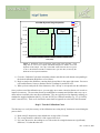
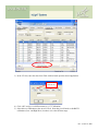
Figures 4(a)-4(c). Upper left (a): Experimental setup showing solid water and the placement of
one (or more) nanoDots. Upper right (b): Flexible water placed over the dosimeter to remove air
gaps and ensure a tissue-equivalent scattering environment. This setup uses a 0.5 cm sheet to
achieve this. Bottom (c): Placement of solid water on top of the flexible to achieve the proper
depth. This setup uses a 1.0 cm sheet giving a total dosimeter depth of 1.5cm including the 0.5cm
from (b).
The bottom half of the picture depicts a semi-infinite scattering medium created from solid-water. The
thickness should be greater than D70% for the beam in question. This is typically 10 cm or more for 6MV.
Next, solid water is placed over the dosimeter to place it a Dmax. This is typically 1.5cm for 6MV. A
flexible slab is recommended to ensure that there are no air-gaps surrounding the dosimeter. Many users
elect to use 0.5cm of flexible water with 1cm of solid water directly above it.
The use of buildup is critical to ensure charged-particle equilibrium (CPE) and, more importantly, to
ensure that electron contamination from head-scattering of the machine or surface scattering from the
patient is eliminated.
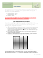
The dosimeters are exposed in groups of 3 to a variety of dose levels depending upon the calibration type
chosen above:
1) Standard (High-Dose): 0, 50 cGy, 150 cGy, 300 cGy
Standard (Low-Dose): 0, 1 cGy, 5 cGy
2) Non-linear – 10 cGy, 100 cGy, 300 cGy, 500 cGy, 800 cGy, 1000 cGy, 1300 cGy
Rev. 2, June 10, 2009