1
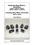
Clearing the Fastest Lap and
Preparing the Performance Monitor for a
Different Circuit
Turn On ignition with any button held pressed.
The display will change to:
Release the button and the display will change
to show your fastest lap (Fastest Time of the
Day):
The display will then change to:
Displaying Your Fastest Lap
Use the top or bottom right hand buttons to
scroll the Gauge window beyond Oil Pressure
so that the display shows:
Recalling Your Lap Times
Enter Recall Mode by pressing both right hand
buttons together. The display changes to:
The SWIS20 Steering Wheel
Instrument System
Operating Manual
Showing the last lap was lap 14 with a lap time
of 1:26:04. Use the right hand buttons to select the maximum temperatures and minimum
pressures in this lap. Here the minimum oil
pressure was 68 psi.
Use the left hand buttons to scroll backwards
and forwards through the lap time memory.
As soon as this display appears, press any
button and the display will change to:
Press both right hand buttons again to exit
Recall Mode.
To Enter Set Up Mode
Press both left hand buttons together and the
display changes to:
Now you have successfully cleared the fastest
lap and told the system to clear the performance monitor memory. DO NOT trigger false
laps with the beacon before going out on your
first lap of a new circuit.
You should do this every time you start a session at a different track.
And then to:
To Clear the Lap Number
Press both top buttons for 3 seconds.
To Clear the Elapsed Time
Press both bottom buttons for 3 seconds.
Page 24
The left hand buttons select the item to be set
up and the right hand buttons change the setting of the item.
Press both left hand buttons again to exit Set
Up Mode.
Revision
Page 11
4.
Using the SWIS20 System
4.1
Odometer
4.2
Gear
4.3
RPM and Shift Lights
Page 2
Use the right hand buttons to change the
gauge reading in this window. Scrolling
beyond Oil P gives Fastest Lap, then
RPM, then Battery voltage, then the
User 1 Channel before flipping back to
Fuel.
Set Up Mode
3.1
General
3.2
Function 0 Tachometer and Other Displays
3.3
Function 1 Set Defaults
3.4
Function 2 Session Number
3.5
Function 3 Hold Time
3.6
Function 4 Blank Time
3.7
Function 5 Infra Red Channel Number
3.8
Function 6 “IN” Channel
3.9
Function 7 Performance Monitor Display
3.10
Function 8 Display Performance in Elapsed Time
Window
3.11
Function 9 Elapsed Time Units
3.12
Function 10 Number of Wheel Pulses
3.13
Function 11 Wheel Circumference
3.14
Function 12 Wheel Turns per Sample
3.15
Function 13 Sample Period
3.16
Function 14 Start Logging Trigger
3.17
Function 15 Number of Tach. Pulses per Two Turns
3.18
Function 16 Tacho Filter
3.19
Function 17 Tacho Pulse Polarity
3.20
Fuel and Other Alarm Limits
3.21
Shift Light Set Up
3.22
Gear Indicator Set Up
3.23
Monitoring Inputs in Set Up Mode
3.24
Function 33 Clear Function
The Elapsed Time is useful during qualifying or endurance races. However this
window can be changed to show seconds only lap time or the performance
monitor.
3.
The Speed window can display speed oil pressure, water temperature or oil temperature. If
speed is not shown here normally, it can be shown
by pressing the top left hand button for 3 seconds—useful for the pit lane. The original display
can be restored by pressing the bottom left hand
button.
The Buttons and Display Windows
2.1
The Buttons
2.2
The Display Windows
2.2.1 The Gear Window
2.2.2 The Laps Window
2.2.3 The Lap Time Window
2.2.3.1 The Performance Monitor Option
2.2.4 The Speed Window
2.2.5 The Elapsed Time Window
2.2.6 The Gauge Window
The Lap Time Window shows lap time, the performance monitor and warnings.
You can set this to show RPM or lap time only. Using the right hand buttons,
the fastest lap time, battery voltage and the user 1 channel can be displayed
here.
2.
This window always
shows lap number
Introduction
Gear can be calculated—not
very satisfactory or can come
from gear position sensor.
1.
The SWIS10-R Steering Wheel
Contents
Page 23
8.3
4.4
4.5
4.6
4.7
4.8
4.9
4.10
4.11
4.12
4.13
4.14
4.15
Aligning The Beacon and IR Detector
The Beacon Beam diverges at 40 degrees and the IR Detector acceptance
cone angle is about 15 degrees. Ensure that the IR Detector will fall within
the Beacon’s beam and, just as important, be sure that the acceptance cone
of the IR Detector includes the Beacon when the car passes it.
IR Detector not aligned correctly
40º
15º
Speed
Elapsed Time
Oil Pressure
Water Temperature
Oil Temperature
Fuel
Battery Voltage
The Lap Timer
Recall Mode
Best Lap (Ftd)
Displaying RPM
The Performance Monitor Option
5.
Data Logging
6.
Data Analysis
7.
Connecting Other Sensors
8.
Beacon Settings and Siting
8.1
Understanding Infra Red Communications
8.2
Aligning the Beacon and Detector
8.3
Beacon Conflicts
IR Detector rotated and aligned correctly
Farringdon Instruments Limited Unit 9 Oriel Court, Omega Park, ALTON.
Hampshire GU34 2YT. Telephone 01420 541591 Facsimile 01420 587212.
www.farringdininstruments.co.uk
Page 22
Page 3
1.
Introduction
Thank you for choosing the Farringdon SWIS20 Steering Wheel Instrument
System. This manual will describe how to use and set up system in your car.
Of course, the system will not work properly until it has been loaded with all
the essential information about your car—for example the circumference of
the wheel. So please take a little time to ensure that you know how to set up
the system before you use it for the first time.
2.
The Controls and What is Displayed
The Steering Wheel Instrument System has four buttons and six display
windows. This section explains how to use the buttons and what is displayed
in the windows.
2.1
The Buttons
Each side of the Instrument Cluster, there is a double membrane push button. These buttons will click when pressed and give an “over-centre” feel.
They are deliberately stiff and will not respond to very short pushes. This
prevents them being pressed accidentally or operated by vibration.
While driving, the left hand buttons will control the brightness of the display
and the right hand buttons select the gauge that is displayed in the gauge
window as follows:
Pressing the top left button increases the brightness one step. Pressing the
bottom left hand button decreases the brightness one step. There are 10
steps in all.
If the LED next to the Oil P legend is lit, the oil pressure in (psi) is shown in
the gauge window. Pressing the bottom right hand button causes the LED
next to the Water legend to light and the water temperature (in degrees centigrade) is shown in the gauge window. Pressing the top right hand button
switches the display back to Oil Pressure. In this way, the right hand buttons
“scroll through” the gauges.
Pressing both top buttons for about 3 seconds clears the lap count. This is
often necessary on the starting grid after passing the lap timing beacon during the parade and warm up laps.
Pressing both bottom buttons for about 3 seconds clears the elapsed time.
This may be done at the start of a qualifying session or the start of an endurance race or session.
8.
Beacon Setting and Siting
8.1
Understanding Infra Red Communications
Infra red light (IR) from light emitting diodes (LEDs) can be turned on and off
very quickly and it is this property that makes infra red ideal for short range
communications. To increase the sensitivity of the receivers, a “carrier”
frequency is used to turn on and off the LED. The receiver can then look for
light that is being modulated at this frequency amongst other background
light. To impose information on the infra red beam, this carrier frequency is
itself turned on and off.
There are two ways in which this form of communication can be interrupted,
first, by any light source strong enough to saturate the receiver - for example
- the sun or another more powerful IR source - and second, other
transmissions using the same carrier frequency.
The reason for the recessed lens and photodiode in the IR detector is to
shield it from direct sunlight so providing the IR detector will not “see” the
setting sun behind the beacon, it will not be saturated by the sun.
However, some other lap timer and data logging systems do use the same
carrier frequency and others use much more powerful IR beams and it is for
this reason that you must take care where the beacon is positioned.
8.2
Beacon Conflicts
From the explanation given in the previous section it is clear that
reliable operation can only be guaranteed when the beacon is sited
away from all others. A distance of 5 metres along the pit wall is
probably safe. The Lap Timer will ignore all infra red signals on the same
carrier frequency that do not contain the Main Channel or IN codes saved in
its memory but if you find that lap times are obviously incorrect, look for
another Beacon using your channel on the pit wall. With only four channels to
choose from, it may be that more than four teams are using Beacons at the
same track. In this case agree to use a single beacon and set all the Lap
Timers to respond to this channel.
It is especially important to site the Beacon away from other beacons using
large external batteries and having a large array of LEDs pointing over the
track. These probably emit very strong IR signals which will saturate your
Lap Timer.
The remaining combinations are pressing both left hand buttons or both right
hand buttons. After holding both left hand buttons for about 3 seconds, the
set up mode is entered. (See Section 3) After holding both right hand buttons for about 3 seconds Recall Mode is entered. (See section 5.2)
Page 4
Page 21
7.
Connecting Other Sensors
Other sensors can be connected to the system through the “User Channels”. The loom has several, up to a maximum of eight, user channel
three pin Mini Sureseal sockets. The pin designations are all the same
and are as follows:
2.2
The Display Windows
There are six display windows:
Pin 1 Ground
Pin 2 Sensor signal
Pin 3 +5 volts
The Sensor signal must range from ground to a maximum of +5 volts.
For potentiometers, simply connect the wiper to the signal pin and +5
volts and ground to either end of the track.
For active pressure sensors—such as those used for brake pressure,
connect the +5 volts and ground to the specified wires and the output
to pin 2. These sensors give an output ranging from 0.5 volts to 4.5
volts. DO NOT use the chassis as a ground connection for any sensor.
Starting from the top left, the windows are:
Gear
Speed/Gauge 2
Laps
Elapsed/Lap Time
Lap Time/RPM
Gauge 1
Connect any screen to the ground pin.
Lamda sensors usually require 12 volts to supply the heater and the
interface box but the output is usually from 0 to 5 volts. Be careful with
the ground wires—do not use the ground in the Mini Sureseal connector as the return for the heater supply.
2.2.1
The Gear Window
Shows the current gear if it can; otherwise this window is blank. If there is a
connection to the Gear Box, then a number 0 or n indicates Neutral. If there
is not gear output from the gear box, then the overall gear ratios in MPH (or
KPH) per 5000 rpm must be entered in Set Up Mode. (see Section 3.22)
Refer to the Podium Flash manual to see how to set the data analysis software to adjust the scale and offset of the sensors.
2.2.2
The Laps Window
This window the number of times the car has passed the Beacon. Note that
this may not be the lap number in a race. The lap number can be reset to 0
by pressing both top buttons for about 3 seconds.
2.2.3
The Lap Time/RPM Window
Lap Time window is used for Lap Time! A quick set up change can be made
to display RPM in this window where cars are being driven on the road. (see
section 3.2) The odometer reading and best lap time are displayed here on
power on.
If any gauge reading passes the limit set in Set Up Mode, an Alarm flashes in
this window. Because 7 segment displays are used there is a limited set of
letters that can be shown so the alarm for Oil Pressure is “Oil”, for Water
Temperature or Oil Temperature it is “Hot” and for Fuel Level or Pressure the
alarm is “Fuel”.
Page 20
Page 5
No oil pressure warning is given unless the engine is running. If the Hold
Time is set to 0 and the car is not moving, warnings are given by flashing the
gauge window.
Scrolling past Oil Pressure gives the following displays:
Lap Time Window
Best lap Time
Engine Speed (RPM)
Battery Voltage
User 1 input
Gauge Window
Ftd
tac
bat
US1
to charge the battery. If the battery is not charged, the real time clock and
calendar will not be able to maintain the data and time.
Tip: A small LED shines from behind the SD card slot under the card door.
This light every time a sample is taken and is turned on while a file is being
terminated. DO NOT remove the card if the LED is on.
6.
Data Analysis
Data analysis is provided by PC software package supplied by PolyLogic
called Podium Flash.
2.2.3.1 The Performance Monitor Option
To look at the data collected, simply remove the SD card and plug it into your
lap top. Instructions for the lap top software are supplied with the CD-ROM.
If the Performance Monitor is switched on, then after the Hold Time has expired (see Section 5) the Lap Time Window shows the difference in time into
the lap between the current and best laps as a time prefixed with a + or—
sign.
Plots such as the one shown above can be displayed using the Podium
Flash Data Analysis package.
2.2.4
The Speed/Gauge 2 Window
Shows the Speed in MPH or KPH. Speed can be shown only over a minimum value that will depend on the wheel circumference and the number of
wheel pulses detected in a full wheel revolution. Alternatively this window
can display a gauge reading. If a gauge reading is displayed here, speed
can be shown by holding the top left hand button down for 3 seconds. The
speed is then shown alternately with the letters SPd to remind you that speed
is being displayed. This is designed for pit lane use and window can be
returned to the gauge reading by pressing the bottom left hand button.
2.2.5
The Elapsed/Lap Time Window
If lap times are shown in the lap time/rpm window then elapsed time from
power on is shown in this window. Pressing both bottom buttons for about 3
seconds will clear this time. It is used to show time into a qualifying session
or an endurance race or driver session.
If RPM is shown in the Lap Time/RPM window, then this window shows lap
time but only the seconds. . For example a lap time of 1 minute 2.38 seconds will be displayed as 2.38.
If the Hold Time is set to 0, and the Performance Monitor is on, the Performance Monitor is shown in this window.
Page 6
Page 19
2.2.6
Minimum Battery Voltage
Maximum RPM for the lap
User 1 reading at the beacon
User 2 reading at the beacon
…
User 8 reading at the beacon
To use the data logging you must set up the tacho pulses, the wheel pulses and circumference and you must decide on the rate at which you want
to record data and what criterion should be used to start logging. These
parameters can be set up on the steering wheel or from Podium Flash, the
data analysis software.
You should set the real time clock in the data logger so that you know
when the data was recorded. The clock can only be set through Podium
Flash. First make sure that the clock on your PC is correct then in the
setup dialogue tick the Set Time check box.
About the files recorded on the SD card.
The files are numbered sequentially from 1 to 999. This number will not
reset unless the non-volatile memory becomes corrupted in which case
everything is set to the default state and the file number is set to 0. The
files have a created and last modified date and time, these are the dates
and times at which logging starts and ends.
The files are read only and cannot be deleted. When the card is full you
must re-format it with Podium Flash. If you are logging at a sample period
of 100 milliseconds, a single 512M byte SD card will last you at least a
season so you may wish to keep this and buy a new one at the start of the
next season.
There are SD cards and SD cards! If you use less than the best you may
not to be able to sample data fast enough and the data will be corrupted.
Also you will need to format the card with Podium Flash before you use it.
Podium Flash will write a setup file to the card at the end of the formatting
procedure and it is sensible to check the setup before using a new card.
Warning, the data logger continues to write data to the SD card until the
power to the data logger (and steering wheel) is switched off. The logger
then requires some time to write data held in buffer memories to the card
and to complete the file. Do not remove the card before at least 4 seconds
has elapsed after the power has been switched off.
In order for the system to complete a file, the back-up battery in the data
logger enclosure must be charged. If you are having trouble writing files to
the card, try leaving power connected to the data logger for an hour or so
Page 18
The Gauge 1 Window
The gauge 1 window shows the value of the selected Temperature, Pressure
or Level as selected by the right hand buttons. Scrolling past Oil Pressure
cause other measurements to be shown in the Lap Time Window and an
appropriate label in the Gauge Window such as tac, Ftd, bat, or US1. (See
Section 2.2.3.4)
3.
Set Up
3.1
General
The system may be set up either from your laptop or through the buttons on
the steering wheel. The set up state is held in memory in the control box and
on the SD card. If the SD card is in the control box , then the setup is taken
from this. If you change the setup with the SD card in the control box, the
setup on the card is changed as well.
To set up the system using your laptop, start the data analysis program,
Podium Flash supplied with the system, and click on the top menu SETUP.
Insert the SD card into the laptop (the Sandisk cards supplied fold in half to
reveal a connector that plugs into your laptop’s USB sockets). Now click on
Logger and the set up pages are displayed. Change the setup to suit your
requirements and click OK. Wait for a few seconds for the setup file to be
written to the card. Remove the card and insert in in the control box. When
the system is switched on, the new setup will be copied to the system.
To enter Set Up Mode, press both left hand buttons for about 2 seconds.
The display will change and show “SetuP” in the Lap Time Window and for a
moment shows what the three bottom windows will contain. The Speed
Window will display the Function Number, the Elapsed Time Window will
show a hint at what function has been selected (as far as possible with the 7segment displays) and the Gauge Window will show the value of the function. This value can be changed with the right hand buttons. For Example,
Function 2 is the Hold Time (the time the lap time should be frozen in the Lap
Time Window after passing the beacon) . When setting up this time, the
Speed Window will display 2, the Elapsed Time Window will display “Hold”
and the Gauge Window will display the time set. Pressing the top right hand
button will increase the time and pressing the bottom right hand button will
decrease it.
Some Functions are On or Off. These are changed by pressing the top right
hand button for On and the bottom right hand button for Off.
Once all the changes have been made, the Set Up Mode can be left by
pressing both left hand buttons together for about 3 seconds.
A table listing the various parameters to set up is shown below. Once you
have used it a few times you will find that the hints are enough to guide you
through the Set Up process.
Page 7
Function
Number
Hint in
Elapsed
Time
Window
0
Tach
SPd
OilP
Cool
OilT
Fu P
Display tachometer in Lap Time Window
Display Speed in the Speed/Gauge 2 Window
Display Oil Pressure in the Speed/Gauge 2
Display Water Temp in the Speed/Gauge 2
Display Oil Temp in Speed/Gauge 2 Window
Display Fuel Pressure (or level) in S/Gauge 2
OFF
OFF
OFF
OFF
OFF
OFF
1
def
Set Everything to Default Values
OFF
2
SESS
Session Number—this automatically increases every time
the system is turned on.
0
3
Hold
Hold Time in seconds. Time that the Lap Time is frozen
after passing the beacon.
30
4
blnc
Blank Time in seconds. Time that the IR receiver ignores
any other input after seeing its beacon.
10
Data logging in the SWIS20 is completely different from previous Farringdon
systems. Data is logged against time, that is every so many milliseconds, all
the channels are read and the results stored on the SD card.
5
IrCh
Channel Number for IR Detector. Choose 0 to receive PI
beacon at UK Tracks.
1
The data collected for each sample is as follows:
6
InCh
IN Channel Number. Set this to IN code of beacon.
100
7
PerF
Performance Monitor Display ON or OFF
OFF
8
Here
Display Performance in Elapsed Time Window
OFF
9
Hour
Elapsed Time in Hours and Minutes (normally in Minutes
and Seconds).
OFF
10
PPt
Pulses per Turn from Wheel Sensor
2
11
Circ
Wheel Circumference in centimetres
180
12
tps
Turns per Sample. Number of wheel turns between PM
sample. DO NOT CHANGE
2
13
Per
Sample Period in milliseconds
100
14
Strt
Start Data Logging Trigger. 0 = never, 1 = when powered
on, 2 = when engine started and 3 = when min. speed
reached. Logging stops when power is turned off.
15
tach
Number of Pulses per Two Engine Revolutions.
4
16
Filt
Tacho Pulse Filter—units are usecs + 50
100
17
POSP
Tacho Pulse Polarity—Positive
ON
AL
Lirn
Alarm Limit for Fuel.
10
Page 8
Function Description
Default
Value
stored in memory every few metres along the track. After the hold time has
expired, the lap time window then displays the difference between the time at
this point on the circuit for this lap and the time for the best lap. This difference is recalculated every few meters and the display updated.
If the lap time is displayed in the upper large window, the time difference is
prefixed with a + or - sign. If it is displayed in the centre bottom window a
negative sign only is available. To use the Performance Monitor, set function
7 (Perf) to ON. Make sure that you clear the best lap at the start of the session and do not switch off the system before starting your out lap.
5
Data Logging
Time into lap (time from beacon)
Speed
RPM
Oil Pressure
Water Temperature
Oil Temperature
Fuel Level or Pressure
Battery Voltage
Lateral G
Axial G
Data Logger Temperature
User 1
User 2
…
User 8
In addition at the end of each lap the following data is collected and stored on
the card.
Lap Time
Lap Number
Session Number
Minimum Oil Pressure
Maximum Water Temperature
Maximum Oil Temperature
Minimum Fuel Level or Pressure
Page 17
The Lap Time may be displayed in the large Lap Time/RPM window or alternatively, in the centre bottom window in place of elapsed time. (See Set UP
for details.)
Function Hint in
Number Elapsed
Time
Window
Function Decription
Default
Value
18
Fu n
Fuel Sensor Output Inverted
OFF
19
Fu d
Fuel Sensor Delay. Delays fuel alarm for 10 seconds
so that fuel alarm is not triggered by cornering.
OFF
AL
Lim
Alarm Limit for Oil Temperature
110
AL
Lim
Alarm Limit for Water Temperature (degrees C)
95
AL
Lim
Oil Pressure Alarm Limit (psi)
20
tac
LedS
Shift Light Settings—Green LED 1 to Red LED 9 (rpm x 10 to 90
100)
20
G ip
Electrical Gear Input Connected
OFF
21
N ip
Neutral Switch Input Connected
OFF
22
Gr 1
Gear 1 mph/5000 rpm (or pot reading)
-
23
Gr 2
Gear2 mph/5000 rpm (or pot reading)
-
24
Gr 3
Gear 3 mph/5000 rpm (or pot reading)
-
25
Gr 4
Gear 4 mph/5000 rpm (or pot reading)
-
26
Gr 5
Gear 5 mph/5000 rpm (or pot reading)
-
27
Gr 6
Gear 6 mph/5000 rpm (or pot reading)
-
As an option available in Set Up, the Lap Time/RPM window can be made to
show RPM rather than lap time. If this option is selected, then the lap time is
shown in the elapsed time window as seconds. After reaching 59.99 the
display rolls over to 0.00. Although the minutes are not shown this display is
adequate for lap timing.
28
Gr n
Potentiometer reading for neutral
-
29
Gr r
Potentiometer reading for reverse
-
4.15
30
Xg
Displays value read from x G sensor
-
The Performance Monitor provides the “unfair advantage” that every driver is
looking for! Further, if you are prepared to entrust you car to someone who
you know will drive faster than you, the Performance Monitor becomes a very
powerful training aid.
31
Yg
Displays value read from y G sensor
-
32
Usr1..8
Displays value read from User (1 .. 8) Input
-
33
Gear
Displays Gear potentiometer reading
The system works as follows:
34
-CL-
Clears Memories. Set to 1 to clear tell-tale
Set to 2 to Clear Lap End Memory
Set to 128 to Clear Odometer. To clear more than one
item enter sum of codes. E.g. to everything enter 131.
(1+2+128).
If the IN channel has been set up correctly, your car can be called into the
pits by switching the beacon to the IN position. The word “Pits” is shown
flashing in the Lap Time/RPM window.
4.12
Recall Mode
If the right hand buttons are pressed together for 3 seconds Recall Mode is
entered. The last lap time is shown in the Lap Time/RPM window together
with the lap number in the Lap window. The right hand buttons may be used
to select a gauge. The gauge reading is the minimum or maximum for that
lap. Minimum pressures and maximum temperatures are recorded. Use the
left hand buttons to scroll through the laps retained in memory.
Pressing both right hand buttons together for 3 seconds causes the system
to exit Recall Mode.
4.13
Best Lap (Ftd)
The best (smallest) lap time is stored and can be displayed by using the right
hand buttons to scroll up to the point where “Ftd” (fastest time of the day) is
shown in the gauge window. The best lap is shown also during the power up
sequence and can be cleared by pressing any button at the next point in the
sequence.
4.14
Displaying RPM
The Performance Monitor Option
The best lap must be cleared at the start of a session at a new circuit. During the first complete lap and on all subsequent laps, the time into the lap is
Page 16
Monitor Mode
Page 9
3.2
Tachometer and Other Display Options
The tachometer option is the first to be accessed so that the Lap Timer may
be switched off and replaced by a digital tachometer. Set to On to display
RPM. This is followed by options for the Speed/Gauge 2 window. The hint
shown in the Elapsed/Lap Time window are as follows:
SPd = Speed
OilP = Oil Pressure
Cool = Water Temperature (or CHT)
OilT = Oil temperature
FuP = Fuel Pressure (or level)
3.3
Set Defaults
Setting this Function to On sets all functions back to the factory settings. Set
to yes then leave set up mode by pressing both left hand keys.
3.4
pit lane. To confirm that speed is being displayed, the speed is shown alternating with the text SPd. To clear the speed display, press the bottom left
hand button.
4.5
Elapsed Time
The elapsed time is displayed in the bottom centre window and can be reset
to zero by pressing both bottom buttons for a second or two. The units are
normally minutes and seconds but can be changed to hours and minutes in
Set Up.
4.6
Oil Pressure
Oil pressure is the measurement of the highest priority and an oil pressure
warning will overrule any other. When the engine is not running an oil pressure warning can be turned off (in the normal way by pressing either right
hand button) but when the engine is running this alarm cannot be turned off.
The alarm given in the Lap time/RPM window is a flashing “OiL”.
Session Number
4.7
Water Temperature
The session number is stored with lap times and data. It is incremented
every time the beacon is seen on the out lap but can be set manually with
this function.
Water temperature is the second highest priority. Its alarm can be turned off
at any time. The alarm is displayed in the Lap Time/RPM window as “Hot”
3.5
4.8
Hold Time
The Hold Time is the time in seconds that the lap time is frozen in the Lap
Time Window after passing the beacon. Set this to be long enough for you to
reach a suitable place on the track to glance down and read it.
Oil Temperature is the third highest priority. Its alarm is also “Hot” but the
gauge LED will be light next to the Oil Temp legend.
4.9
Setting the Hold Time to 0 changes three aspects of the display. First the lap
time remains displayed throughout the lap, second, the Performance Meter is
shown in the Elapsed Time window and third, gauge warnings are signified
by a flashing gauge window until the car is moving.
3.6
Blank Time
This is the time that the Infra Red Detector ignores all signals after seeing its
beacon. 10 seconds is a good time to use but it can be extended to blank
out other beacons placed around the track in order to generate segment
times on some other systems.
3.7
Infra Red Channel Number
Set this to the channel number you are going to use. If you wish to use the
PI Beacons on most UK circuits and you have a dual channel IR Detector,
then set the channel number to 0.
Page 10
Oil Temperature
Fuel
Fuel level or pressure is the lowest priority and its alarm is “Fuel”.
4.10
Battery Voltage
Battery voltage can be displayed in the Lap Time/RPM window by pressing
the top right hand button until “Bat” is shown in the gauge window. There is
no warning for battery voltage.
4.11
The Lap Timer
When switched on the steering wheel enters its power up sequence before
reaching its normal state. The lap time starts at 00:00.00 and increments
continuously until it sees the beacon for the first time. The lap time is then
frozen for the “hold” time. The hold time is adjustable in Set Up. The number of laps completed is shown in the two digit lap window. (The number
rolls over from 99 to 0.)
Page 15
4.
Using the SWIS20
When power is applied, the steering wheel first displays all segments (all
numbers are 8s). They are then cleared and the serial numbers of the steering wheel itself (in the Speed/Gauge 2 window), the serial number of the data
logger (in the lap time/RPM window) and the software revision (in the gear
window) are displayed. If no button is pressed while the serial numbers are
displayed, the remainder of the power-up sequence is skipped. If any button
is pressed the odometer reading is shown next.
4.1
Odometer
The odometer (total distance travelled) is displayed when the steering wheel
powers up. It can be cleared back to zero by using function 34 in the set up
procedure. It shows the total number of whole miles (or kilometres) travelled
since it was last reset.
4.2
Gear
The gear window shows the gear selected. If the gear is calculated from
engine RPM and road speed, remember that it can only show the correct
gear after you have released the clutch. It cannot show you that you are
about to select the wrong gear. Further, it will not show the gear until the car
is travelling fast enough to obtain a valid speed.
On the other hand, if the gear signal comes from a sensor in the gearbox,
then this will show the gear when the car is stationary and at all other times.
4.3
RPM and Shift Lights
Experiment with the shift light settings to find the most easily read arrangement. You may find that the lights should be set to light at small intervals
(200 rpm or so) at the top of the RPM range to allow you to gauge the rate at
which the RPM is approaching the shift point.
4.4
Speed
Speed can be shown all the time or on demand in the in the Speed/Gauge 2
window . (see Set Up) The speed is calculated from the time between the
pulses coming from the wheel sensor. Because this timer can measure only
small times, speed cannot be shown until some minimum value is reached.
This value depends on the number of pulses per wheel turn from the wheel
sensor and the diameter of the wheel. Typically the lowest speed that can be
displayed is between 10 and 30 mph.
If the Speed/Gauge 2 window is displaying another gauge, then pressing the
top left hand button for about 2 seconds causes the Speed/Gauge 2 window
to show speed. This function has been added to monitor your speed in the
Page 14
3.8
“IN” Channel Number
All Farringdon Beacons come with an channel number from 1 to 250. Set
this channel number to that of your beacon. This is most easily done by
pointing the beacon, switched to “IN” at the IR Detector while at this point in
the set up procedure. The Gauge Window will show the channel number
detected.
3.9
Performance Monitor Display
The Performance Monitor shows the time difference in the Lap Time Window
between the time to the current point on the track and the time taken in the
Best Lap to reach the same point. It is shown only after the Hold Time has
expired. If you turn this display ON, then the data logging must be ON; so
setting this function ON also sets the Data Logging function ON. Remember
to clear the best lap when you visit a different track.
3.10
Display Performance Monitor in Elapsed Time Window
Set this to ON to display the Performance Monitor in the Elapsed Time Window. No + sign is shown but a—sign is displayed when you are faster than
your best lap.
3.11
Elapsed Time Units
Elapsed Time can be measured in minutes and seconds or hours and
minutes. The latter is useful for endurance races.
3.12
Number of Wheel Pulses per Turn
Enter the number of pulses the wheel sensor will generate for each tuen of
the wheel—the number of targets.
3.13
Wheel Circumference
Enter the wheel circumference in centimetres. The circumference is best
measured by marking the tyre on the wheel to which the sensor is attached
and rotating it at least twice, measuring the distance covered and dividing by
the number of times the wheel was turned.
To show the speed in KPH, divide the circumference by 1.6 and enter this
value.
3.14
Wheel Turns per Sample
The Performance Monitor (if fitted) will calculate the number of wheel turns
counted between sampling the time from beacon. This function displays the
result. Do not change.
Page 11
3.15
Sample Period
3.22
Gear Indicator Set Up
Enter the sample time you want to use. A good figure for comparing driving
style would be 100 msecs. If you have suspension potentiometers on the
User channels, you may wish to sample much faster. The maximum sampling speed is 500 samples per second—for this enter a sample period of 2
milliseconds. At this rate you should be able to see frequencies of 100 HZ.
There are three items to be set up for the gear indicator to work correctly. If
there is an analogue output from the gearbox—usually a potentiometer, then
set function 20 to ON. Connect the potentiometer across the +5V and Ground
outputs. Use Function 33 to monitor the values for each gear and enter these
in Functions 22 to 29.
3.16
If there is not direct output from the gearbox, then the gear ratios have to be
entered in set up mode so that the system can deduce the gear the car is using. The ratios are expressed as miles per hour per 5000 rpm. (If you have
chosen to use KPH by dividing the wheel circumference by 1.6, then enter the
ratios as KPH per 5000 RPM.) If the gearbox is a sequential type then there
may be a neutral switch. In this case the switch must go to ground when in
neutral and Function 17 should be set to ON. The display will show a blank if
the engine or car is not running fast enough but will show 0 only when the neutral switch is actuated.
Start Logging Trigger
Enter the code as follows: 0 = never. 1 = when ever power is applied, 2 =
when a speed of 40 mph is reached and 3 = when the engine has started.
We recommend the latter as it gives important diagnostic data while the engine is being warmed up. Data logging stops when power is removed.
3.17
Number of Tachometer Pulses for Two Revs. Of the Engine
The number entered depends on your ignition system. If electronic ignition is
used, then there will probably be a tacho pulse output. If not it may be necessary to purchase an HT sensor which clips on to a plug lead which will
produce just one pulse per two turns for a 4 stroke engine.
3.18
Tacho Filter
Often pulses from the ignition system are noisy and have to be filtered to give
reliable tacho readings. This function sets the minimum pulse widths that are
counted as tacho pulses. The units are in microseconds plus 50. Set this to
100 as a start.
3.19
Tach Pulse Polarity
This is set to positive by default. (Positive Polarity ON.)
3.20
Fuel and Other Alarm Limits
It is recommended that you not change the default settings for the alarm
limits for fuel, oil temperature and pressure and water temperature—these
have been specified by the Radical factory.
3.21
Shift Light Set Up
The shift lights are set up following the alarm limits. Set the value to the
RPM/100 at which you want the LED to light. You can set more than one
light to the same value so that, for example the top three bright LEDs can be
set up to come on at the same RPM.
Page 12
Use the following equation (or a gear ratio chart) to calculate these figures.
(circumference) x (Gear Ratio ) x (Final Drive Ratio) x 1.863 = mph/5000 rpm.
Or (circumference) x (Gear Ratio ) x (Final Drive Ratio) x 3 = kph/5000 rpm.
Where (circumference) is the wheel sensor wheel circumference in centimetres.
3.23
Monitoring Inputs in Set Up Mode
A very useful Monitoring Mode is available in Set Up. Functions 30 to 33 read
out the values of each axis from the Accelerometer, all 8 User Channels and
the gear pot. Use the values to check the working of any sensors you have
connected to the User Channels and to check the accelerometer. The figures
displayed are the outputs of the system ADC and range from 1023 for an input
of 5 volts (the maximum) and 0 for ground voltage. (The display wraps round
after 999 so 1024 reads as 23.)
3.24
Clearing System Memories
Function 30 allows three memories to be cleared. Setting the function to 1 will
clear the tell-tale reading, setting it to 2 will clear the Lap End memory and
setting it to 128 will clear the Odometer. To clear more than one at a time,
simply add the values together. For example to clear the tell-tale and the Lap
End memory, enter 3.
Page 13