1
Sontay SonNet & Tridium JACE Integration User Manual Version 2.0 March 2014
®
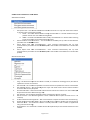
Page 1 of 47 Audience This manual is intended for specifiers, users and installers of the Sontay® SonNet radio sensor system. Content This manual provides a complete reference for the integration of the Sontay® SonNet radio sensor system to Tridium JACE. Related Documents The Sontay® SonNet radio sensor system Site Survey Kit Quick Start Guide The Sontay® SonNet radio sensor system Site Survey Kit Manual The Sontay® SonNet radio sensor system Quick Start Guide The Sontay® SonNet radio sensor system product datasheets Page 2 of 47 Table of Contents: Overview .................................................................................................................................................. 4 Environmental .......................................................................................................................................... 4 Battery Fitting and Replacement .............................................................................................................. 4 Disposal of Batteries ................................................................................................................................. 4 Devices Types ........................................................................................................................................... 5 Battery Powered Nodes ............................................................................................................. 5 24V Powered Routers ................................................................................................................. 7 230Vac Powered Routers ........................................................................................................... 9 24V Powered Routers ................................................................................................................. 9 The System Receiver ................................................................................................................ 10 The RF‐IOM .............................................................................................................................. 10 The Radio Network ................................................................................................................................. 12 Network Planning Considerations ............................................................................................ 13 The Radio System ................................................................................................................................... 15 Security ................................................................................................................................................... 15 How the Self‐Healing Tree Network is Formed ...................................................................................... 15 Propagation Of Radio Signals in Buildings .............................................................................................. 16 Extension Aerials .................................................................................................................................... 17 SonNet‐Tridium JACE Driver Action Menus ........................................................................................... 18 Network Action Menu .............................................................................................................. 18 Receiver Action Menu .............................................................................................................. 18 Router Action Menu ................................................................................................................. 19 RF‐IOM Action Menu ................................................................................................................ 20 Sensor Action Menu ................................................................................................................. 21 Managing a Tridium JACE SonNet Wireless Network ............................................................................. 23 Requirements ........................................................................................................................... 23 Installing the SonNet Driver to a Tridium JACE ........................................................................ 23 Adding a SonNet Network........................................................................................................ 24 Prerequisites ............................................................................................................................ 24 Commissioning a SonNet Network ......................................................................................................... 25 Commissioning an Existing Network ........................................................................................ 25 Commissioning a New Network ............................................................................................... 26 Configuring Network Devices ................................................................................................................. 27 Device Prefixes ......................................................................................................................... 27 Receiver .................................................................................................................................... 27 Routers ..................................................................................................................................... 28 RF‐IOMs .................................................................................................................................... 29 Writing Output RF‐IOM Values ................................................................................................ 30 RF‐IOM Fallback Values ............................................................................................................ 30 End Devices (EDs) ..................................................................................................................... 32 The VFC Activation Count Point ............................................................................................... 33 Commissioning Multiple Networks on the Same Site ............................................................................ 34 Pre‐commission each network away from site ........................................................................ 34 Commission each network individually on site ........................................................................ 34 Best Practise Points ................................................................................................................................ 35 Trouble‐Shooter’s Guide ......................................................................................................................... 36 Estimating Network Coverage in the Absence of a Site Survey ............................................................. 41 Attenuation Properties of Common Building Materials .......................................................... 42 Strategy Tips ........................................................................................................................................... 43 Alarms .................................................................................................................................................... 47 Page 3 of 47 Overview The wireless nodes are based on direct‐sequence spread spectrum communication in the 2.4 ‐ 2.5GHz band, compliant with IEEE 802.15.4‐2006. All nodes have a unique MAC address, equivalent to a unique serial number. All nodes have a PCB‐mounted on/off switch or jumper. All nodes retain their configuration properties across a power failure. Environmental
Storage temperature range of ‐10 to +80°C
Storage relative humidity range of 0 to 90% (non‐condensing).
Ambient (operating) temperature range of ‐10°C to +50°C
Ambient (operating) relative humidity range of 0 to 90%, (non‐condensing). Battery Fitting and Replacement When a battery is installed, or when it is replaced, observing the correct polarity is very important. Fitting the battery incorrectly may result in permanent damage to the device. Recommended batteries are 3.6Vdc 2.4Ah AA size Lithium‐Thionyl Chloride types for space housing sensors, or 3.6Vdc 2.1Ah 2/3 A size Lithium‐Thionyl Chloride types for plant housing sensors, and are not rechargeable. This type of battery should be stored in a clean, cool (not exceeding +30°C), dry and ventilated area. Disposal of Batteries ‐ Warning! Fire, Explosion and Burn Hazard Do not short‐circuit, crush, disassemble, heat above 100°C (212°F), incinerate, or expose the battery contents to water. Do not solder directly to the cell. NB ‐ All batteries must be disposed of in accordance with EC Directive 2006/66/EC, amended by EU Directive 2008/12/EC. Page 4 of 47 Devices Types Battery Powered Nodes Battery powered sensor nodes are used in conjunction with the Sontay® RF‐RX20, RF‐RX40, RF‐RXS and RF‐
RXS‐N receiver units, and if required (depending on installation topography), Sontay® RF‐RR series of routers. Data is transmitted back to the receiver at configurable time intervals, or on a configurable change in measured value. Each sensor retains these configurations if the battery becomes discharged or requires replacement. The sensors automatically find the best path back to the receiver, which may be directly to the receiver or via “parent” routers. To power a battery powered node, jumper J400 must be fitted. To switch off, remove J400. Battery powered nodes are available in 4 formats: Space mounting temperature, with setpoint, momentary switch, fan speed, VFC input and CO2 options o NB ‐ setpoint, momentary switch and fan speed options are not available with the CO2 option Space mounting RH&T, with setpoint, momentary switch, fan speed, VFC input and CO2 options o NB ‐ setpoint, momentary switch and fan speed options are not available with the CO2 option Plant mounting temperature Plant mounting RH&T Space Mounting Specification: Radio Output: Frequency 2.4GHz 16 channels, automatically selected, direct‐sequence spread spectrum Compliance IEEE 802.15.4‐2006 Aerial Characteristics: Gain 1.2dBi VSWR 1.5:1 Data Encryption: AES 128 Power Output: 0dBm (1mW @ 50Ω) Accuracy: Temperature ±0.3°C Optional RH ±3% RH Battery Type: 3.6V AA 2.4Ah Li‐SOCl2, non‐rechargeable Battery Life: >3 years (depending on configuration) Housing: Material: ABS (flame retardant) Dimensions: 115 x 85 x 28mm Environmental: Operating: Temperature: ‐10°C to +50°C RH: 0 to 90%, non‐condensing Storage: Temperature: ‐10°C to +80°C RH: 0 to 90%, non‐condensing Country of origin: UK Refer to product datasheets for installation instructions. Page 5 of 47 Plant Mounting Specification: Radio Output: Frequency 2.4GHz 16 channels, automatically selected, direct‐sequence spread spectrum Compliance IEEE 802.15.4‐2006 Aerial Characteristics: Gain 2.0dBi VSWR 2:1 Data Encryption: AES 128 Power Output: 0dBm (1mW @ 50Ω) Accuracy: Temperature ±0.3°C Optional RH ±3% RH Battery Type: 3.6V AA 2.4Ah Li‐SOCl2, non‐rechargeable Battery Life: >3 years (depending on configuration) Housing: Material: ABS (flame retardant type VO) Dimensions: 115 x 85 x 28mm Mounting: Holes 4mm spaced 85mm apart Protection: IP65 Environmental: Operating: Temperature: ‐10°C to +50°C RH: 0 to 90%, non‐condensing Storage: Temperature: ‐10°C to +80°C 0 to 90%, non‐condensing RH: Country of origin: UK Temperature Sensor Types: Duct Outside air Outside air with solar radiation shield Immersion Strap‐on Flying lead Refer to product datasheets for installation instructions. Page 6 of 47 24V Powered Routers 24V powered routers are used in conjunction with the Sontay® RF‐RX20, RF‐RX40, RF‐RXS and RF‐RXS‐N receiver units, RF‐IOM IO modules and RF‐RS series of battery powered radio sensors, and are used to route signals from battery powered nodes and other routers to the receiver module, where the signal strength of a direct path is not sufficient for reliable communications. NB Each router can support a maximum of 16 “children”, which can consist of a maximum of 8 battery powered nodes and 8 routers, or up to 16 routers if there are no battery powered nodes. Consideration should be given on network planning for redundancy in case of router failure or damage. Data is transmitted back to the receiver at configurable time intervals, or on a configurable change in measured value. Each sensor retains these configurations if the battery becomes discharged or requires replacement. Routers automatically find the best path back to the receiver, which may be directly to the receiver or via other “parent” routers. To power a router, jumper J200 must be fitted. To switch off, remove J200. 24V powered nodes are available in 5 formats: Space mounting temperature, with setpoint, momentary switch, fan speed, VFC input, PIR and CO2 options o NB ‐ setpoint, momentary switch and fan speed options are not available with the CO2 option Space mounting RH&T, with setpoint, momentary switch, fan speed, VFC input, PIR and CO2 options o NB ‐ setpoint, momentary switch and fan speed options are not available with the CO2 option Plant mounting with no sensor functions Plant mounting temperature Plant mounting RH&T Space Mounting Specification: Radio Output: Frequency 2.4GHz 16 channels, automatically selected Direct‐sequence spread spectrum Compliance IEEE 802.15.4‐2006 Aerial Characteristics: Gain 1.2dBi VSWR 1.5:1 Data Encryption: AES 128 Power Output: +10dBm (10mW @ 50Ω) Accuracy: Temperature ±0.3°C Optional RH ±3% RH Power Supply: 24Vac/dc Housing: Material: ABS (flame retardant) Dimensions: 115 x 85 x 28mm Environmental: Operating: Temperature: ‐10°C to +50°C RH: 0 to 90%, non‐condensing Page 7 of 47 Storage: Temperature: ‐10°C to +80°C RH: 0 to 90%, non‐condensing Country of origin: UK Refer to product datasheets for installation instructions. Plant Mounting Specification: Radio Output: Frequency 2.4GHz 16 channels, automatically selected, direct‐sequence spread spectrum Compliance IEEE 802.15.4‐2006 Aerial Characteristics: Gain 2.0dBi VSWR 2:1 Data Encryption: AES 128 Power Output: +10dBm (10mW @ 50Ω) Accuracy: Temperature ±0.3°C Optional RH ±3% RH Power Supply: 24Vac/dc Housing: Material: ABS (flame retardant type VO) Dimensions: 115 x 85 x 28mm Mounting: Holes 4mm spaced 85mm apart Protection: IP65 Environmental: Operating: Temperature: ‐10°C to +50°C RH: 0 to 90%, non‐condensing Storage: Temperature: ‐10°C to +80°C RH: 0 to 90%, non‐condensing Country of origin: UK Temperature Sensor Types: Duct Outside air Outside air with solar radiation shield Immersion Strap‐on Flying lead Refer to product datasheets for installation instructions. Page 8 of 47 230Vac Powered Routers The 230Vac powered RF‐RR‐MPR routers can be used in conjunction with the Sontay® RF‐RX20, RF‐RX40, RF‐
RXS and RF‐RXS‐N receiver units, RF‐IOM IO modules, 24V powered RF‐RR routers and RF‐RS series of battery powered radio sensors, and are used to route signals from battery powered nodes and other routers to the receiver module, where the signal strength of a direct path is not sufficient for reliable communications. NB Each router can support a maximum of 16 “children”, which can consist of a maximum of 8 battery powered nodes and 8 routers, or up to 16 routers if there are no battery powered nodes. Consideration should be given on network planning for redundancy in case of router failure or damage. NB ‐ the RF‐RR‐MPR 230Vac has no sensor capability. Specification: Radio Output: Frequency 2.4GHz 16 channels, automatically selected Direct‐sequence spread spectrum Compliance IEEE 802.15.4‐2006 Aerial Characteristics: Gain 2.0dBi VSWR <2:1 Data Encryption: AES 128 Power Output: +10dBm (10mW @ 50Ω) Power Supply: 85 – 240Vac @ 50/60 Hz Housing: Material: ABS (flame retardant) Dimensions: 116 x 106 x 52mm Environmental: Ambient: Temperature: ‐30°C to +70°C RH: 0 to 90%, non‐condensing Protection: IP30 Page 9 of 47 The System Receiver The SonNet® receiver collects data from all other devices on the radio network, including measurements from sensors, link quality for all links formed in the network, battery levels for all battery powered devices, hours run for all devices and the current status of all devices. NB Each receiver can support a maximum of 16 “children”, which can consist of a maximum of 12 battery powered nodes and 4 routers, or up to 16 routers if there are no battery powered nodes. NB ‐ If the USB port of an RF‐RXS receiver is connected, the 9‐way serial port is temporarily disabled until the USB port id disconnected again. Receivers are available in 4 formats:
RF‐RXS ‐ Serial output and USB port for use with CMS
RF‐RXS‐N ‐ Option card for Tridium JACE controllers Receiver Specification: Radio Output: Frequency 2.4GHz 16 channels, automatically selected Direct‐sequence spread spectrum Compliance IEEE 802.15.4‐2006 Aerial Characteristics: Gain 2.0dBi VSWR 2:1 Data Encryption: AES 128 Power Output: +10dBm (10mW @ 50Ω) 24Vac/dc Power Supply: Environmental: Operating: Temperature: ‐10°C to +50°C RH: 0 to 90%, non‐condensing Storage: Temperature: ‐10°C to +80°C RH: 0 to 90%, non‐condensing Country of origin: UK Refer to product datasheets for installation instructions. The RF‐IOM The RF‐IOM has no “intelligence”, but merely acts as local I/O with connectivity to typical HVAC equipment such as fan coil units (FCUs) and variable air volume (VAV) boxes. The RF‐IOM reads its digital and analogue inputs and transmits the values wirelessly to a BMS controller via either a SonNet V2 serial receiver or a SonNet option card receiver. The RF‐IOM receives its output values wirelessly from a BMS controller via either a SonNet V2 serial receiver or a SonNet option card receiver. Additionally, the RF‐IOM has full router functionality. Typically, a simple system will consist of; Battery powered EDs Page 10 of 47
Powered routers (if required) SonNet V2 serial receiver or a SonNet option card receiver RF‐IOMs The EDs (and routers, where applicable) operate in the normal way. Data from the receiver is made available to the controller via a serial link. The SonNet data points are then used by the controller as part of a control strategy, which will typically calculate heating and cooling demands, damper positions etc. These calculated control values will then be passed back to the receiver via the serial link and passed from the receiver over the wireless network to the RF‐IOM. The RF‐IOM outputs are defined as points in the JACE so that their values can be set by the control strategy via the receiver. Note that the RF‐IOM cannot be used with the RF‐RX20 or RF‐RX40 receivers. RF‐IOM Specification: Radio Output: Frequency 2.4GHz 16 channels, automatically selected Direct‐sequence spread spectrum Compliance IEEE 802.15.4‐2006 Aerial Characteristics: Gain 2.0dBi VSWR 2:1 Data Encryption: AES 128 Power Output: +10dBm (10mW @ 50Ω) Power Supply: 24Vac/dc Inputs: 4 x universal inputs; 4‐20mA (loop or externally powered), into 750Ω maximum impedance 0‐10Vdc, into 4k7Ω minimum impedance Resistive, 1.5kΩ min to 60kΩ max Digital, VFC Outputs: 4 x 0‐10Vdc linear, @ 20mA per output LED Indication: Network Data Digital input Housing: DIN Rail H86mm x W58mm x L104mm (excluding aerial) Environmental: Operating: Temperature: ‐10°C to +50°C RH: 0 to 90%, non‐condensing Storage: Temperature: ‐10°C to +80°C RH: 0 to 90%, non‐condensing Country of origin: UK Page 11 of 47 The Rad
dio Network m is compriseed of a rece
eiver, battery powered seensors, RF‐IOMs and A Sonttay® SonNet radio system
nently powereed routers. perman
nsing elementts, accomplishhing both rou
uter and Routerss, though perrmanently powered, can aalso have sen
sensorss functions. Ro
outers, RF‐IOMs and sensoors can eitherr communicatte directly witth the receive
er or via other ro
outers. RF‐IOM
Ms and routers are requireed to be perm
manently powered as they need to stay “awake” at all times to allow signals from “child” node s to be instan
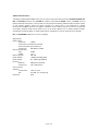
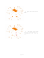
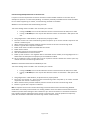
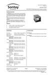
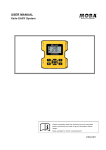
ntly forwarded to their “paarent” nodes.. Battery powereed sensors onlly “wake” for vvery short perriods to send data. matic above, rrouters R2 to R7 have In the schem
5 children each, e
all batteery powered sensors. Their parentt is the receiiver. Router R1 R has 6 children and
d R8 has 4 chhildren, givingg a total number of network devvices of 50, including the receiver.. The recceiver can sup
pport a maximum of 16 ddirectly conne
ected “child” devices, of w
which only 12
2 can be battery powered nod
des, plus up to
o 4 routers. Ms and routerss can support a maximum of 16 directlyy connected “cchild” devicess, of which on
nly 8 can RF‐IOM
be batteery powered nodes, plus up
p to 8 routerss. m depth There can bbe a maximum
of 8 laye rs of routerrs in a m of 150 network annd a maximum
nodes per nnetwork with the RF‐
RX series off receivers. Page 12 of 47
Note th
hat battery po
owered device
es can only rooute their sign
nals to the recceiver directlyy or through RF‐IOMs and rou
uters, and not through othe
er battery pow
wered device
es. planning a Son
nNet radio network, it is re commended tthat the Sonta
ay® SonNet Sitte Survey Kit be used. When p
This easy‐to‐use pacckage allows installers to ttest signal strrengths betwe
een locations s required forr battery d the receiverr prior to instaalling the full system. It can
n also identifyy whether rou
uters are powereed sensors and
needed
d to ensure reeliable commu
unications beetween all devvices on the n
network backk to the receivver. This removees any guessw
work from planning a systtem and allow
ws the installer to order exactly and only o
the devicess required. Net radio senssor system Sitte Survey Kit Q
Quick Start Gu
uide and The Sontay® SonN
Net radio See thee Sontay® SonN
sensor ssystem Site Su
urvey Kit Man
nual for full deetails. onsiderationss Networrk Planning Co
planning a SonNet radio system, it is alw
ways worth co
onsidering the
e placement oof routers, and
d should When p
be capaable of handlin
ng the conseq
quences of a rrouter failing o
or being dama
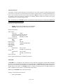
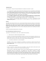
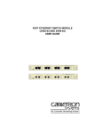
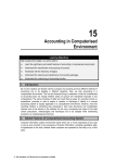
aged. Example: with a require
ement for 16 EEDs: Consideer a network w
ed, as 16 1. At least one rouuter is require
onnected ED
Ds will exce
eed the directly co
maximum limit of 12. Four EDs will be orphaned.
s
router (R1) will wo
ork, but 2. A single gives no red
dundancy if thhe router shou
uld fail. Page 13 of 47
uters, R1 3. Optimal networrk uses 2 rou
and R2. f
the 4. If either of thhe routers fail, maintained, as the 2 network can still be m
orphaned EDs E
can re‐rroute via the other router. Page 14 of 47
The Radio System The radio system used by the Sontay SonNet devices is divided into 3 sections or ‘layers’. 1. The radio layer is where physical control of the radio signal is done. This conforms to international standard 802.15.4, and determines the frequency of the radio signals, the number of ‘channels’ available for use, the bandwidth and power level of the signal etc. There are 16 channels available, and the best one is automatically selected by the receiver. The frequencies used are in the ISM (Industrial, Scientific and Medical) 2.4GHz band, with a maximum data rate of 250kb/s. 2. The network management layer is where the self‐healing tree functionality is run, which controls network topology. ‘ZigBee’ is an example of a network management MESH protocol. SonNet does not use ZigBee, but instead uses a ‘self‐healing tree’ protocol to control network topology. 3. The application layer determines what the device does – i.e. makes it a temperature sensing device, a router or a receiver. SonNet devices use specific applications, and include features such as configuration properties. Security All SonNet system devices have the same, unique network identifier. Only devices with the correct ID will be allowed to join the network. The ID used by system devices is different from the ID used for site survey kit (SSK) devices. Hence, SSK devices cannot join a system network and vice versa. When a SonNet system network has been formed, it can be ‘locked’ to prevent any unauthorised devices joining, even if they are SonNet devices. Niagara WorkPlace AX can be used to subsequently authorise extra SonNet system devices if required. All data transmitted by SonNet devices is encrypted. How the Self‐Healing Tree Network is Formed The network is formed based on 3 rules, and in a specific order of priority. 1. How many ‘tiers’ a device is away from the receiver. If a device can communicate directly with the receiver, it will, even if the link quality is poorer than if it went through a router. If a device has a choice of more than one router, it will always choose the router closest to the receiver (the least number of tiers away), even if the link quality is poor. 2. The number of ‘child’ devices a router already has. A RF‐IOM or router can have a maximum of 16 ‘children’. If a device has a choice of more than one router of the same tier level, it will always choose the router with the least number of children, even if the link quality is poor. 3. Signal Strength (link quality). Finally, if a device has a choice of more than one RF‐IOM or router of the same tier level and the same number of children, it will choose the router with the best link quality. If, for any reason, a device (ED, RF‐IOM or router), loses its preferred path back to the receiver, it will automatically search for an alternative – still obeying the 3 rules above in sequence. If, despite employing Direct Sequence Spread Spectrum (DSSS) techniques, interference on the currently occupied channel prevents communications, the receiver will automatically look for another channel which is clear. All other devices, having lost their links to the receiver, will then also automatically scan the 16 channels until they find the receiver again, and the network will re‐form without user intervention. Page 15 of 47 o Signals in Bu
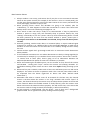
uildings Propagaation of Radio
opagation of m
microwave rad
dio signals in aa building can be affected in
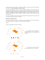
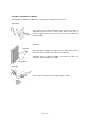
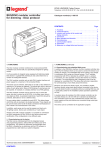
n several wayss: The pro
Attenua
ation en it passes thhrough air. Siggnals are Radio signal strength is atttenuated whe
much more when passing through otther media, such as attenuated m
materials typpically used in
n construction, such as brrick, stone, wo
ood and especially steeel. Reflection Re
eceiver
ng, radio signa
als can take m
many paths from f
the Depending oon the buildin
transmitter too the receiverr, rather than just one singlee path. h
the effe
ect of cancellling each oth
her out, ‘Multipath’ ssignals can have reducing oveerall received ssignal strength
h. Transmittter
Scatteriing uce its signal sstrength. Scattering th e radio signal can also redu
Page 16 of 47
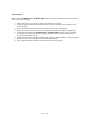
Extension Aerials When using the RF‐AERIAL‐PM2 or RF‐AERIAL‐PM5 extension aerials, it is important to observe some basic rules for siting and mounting. 1. Always ensure there is a much clear space around the aerial as possible. 2. Generally speaking, where possible mount the aerial as high as possible on the same floor as the routers and EDs 3. Don’t mount between metal surfaces (for example steel I‐beams) in ceiling spaces 4. Wherever possible, mount the aerial on a metal ground plane (such as the top of a metal panel) 5. The coaxial cable used for the RF‐AERIAL‐PM2 or RF‐AERIAL‐PM5 extension aerials is semi‐rigid and should not be bent at too sharp an angle or too tight a radius. It is recommended that the minimum bending radius is 5cms 6. Always mount the aerial vertically. This produces the optimum radiation pattern and signal strength 7. Extension aerials can be used with receivers and RF‐IOM modules. 8. Aerial extensions should not exceed 5m to prevent excessive loss of signal. Page 17 of 47 SonNett‐Tridium JACE Driver Actio
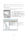
on Menus Networrk Action Menu i.
ii.
iii.
iv.
ommand deteermines wheth
her the driver can only findd nodes if the receiver Set System Lock – This co
is placed in auto‐commissioning modee ed to a receivver without having to a. FALSE = The drivver will find nnodes alreadyy commissione
mmissioning m
mode. putt the receiver into auto com
b. TRU
UE = The drivver will not finnd nodes already commissiioned to a recceiver withou
ut having to put the receivver into auto ccommissionin
ng mode. munications – This comman
nd automatica
ally sets up seerial commun
nications Assert Seriaal Card Comm
parameters for the RF‐RX
XS receiver ot1 Communnications – This T
command automati cally sets up serial Assert Opttion Card Slo
communications parameters for the R F‐RXS‐N optio
on card receivver connectedd to slot 1 on tthe JACE (COM3) ot2 Communnications – This T
command automati cally sets up serial Assert Opttion Card Slo
communications parameters for the R F‐RXS‐N optio
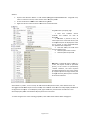
on card receivver connectedd to slot 2 on tthe JACE (COM4) Receiveer Action Menu i.
ii.
iii.
iv.
v.
vi.
vii.
viii.
ix.
x.
Ping – This ccommand req
quests the recceiver runtime
e, as a method on checkingg comms, butt doesn’t update the receiver runtime field mand requestss the receiverr runtime and updates the rreceiver runtime field Get Runtimee – This comm
Get Softwarre Version – T
This commandd gets the major and minorr versions of tthe receiver firmware and stores tthe result as p
properties De‐authorisse Node – Thiss command dee‐authorises aand removes the receiver ffrom the netw
work (NB Only works when auto co
ommissioning is off) mand refreshess all data, excluding the “pa
arent” properrty Get All Dataa – This comm
Get RF Channel – This co
ommand getss the current 2.4GHz RF ch
hannel (valid channels are 11 – 26 inclusive) o Commissioning Mode – Thhis command sends a request to enable auto commisssioning Enable Auto
Disable Auto
o Commission
ning Mode – TThis command
d sends a requ
uest to disablee auto commissioning Authorise Node N
– This command is uused to manually authorise
e a node or nnodes (as opp
posed to using auto ccommissioningg) Map Netwo
ork – This com
mmand is usedd to discover aand update the parent nodee of all device
es on the network Page 18 of 47
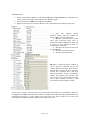
Action Menu Router A
i.
ii.
iii.
iv.
v.
vi.
vii.
viii.
ix.
x.
xi.
quests the roouter runtime, as a method
d on checkingg comms, but doesn’t Ping – This command req
update the router’s runtime field mand requestss the router’s runtime and updates the rruntime field Get Runtimee – This comm
Get Softwarre Version – T
This commandd gets the maajor and mino
or versions off the router firmware and stores tthe result as p
properties De‐authorisse Node – This command dde‐authorises and removess the router frrom the netw
work (NB Only works when auto co
ommissioning is off) mmand refresshes all the data d
specific to the selectted router, excluding Get All Datta – This com
“parent” pro
operty Get Parent LQI – This co
ommand gets radio link strrength (LQI = Link Quality Index) to the
e node’s parent Configuration
n – This comm
mand requests the following
g configuratio n properties; Get Sensor C
a. Has Temp – Whe
ether the nodde has a temperature senso
or fitted her the node hhas an RH sensor fitted b. Has RH – Wheth
Whether the nnode has a settpoint adjustm
ment pot fittedd c. Has Setpoint – W
hether the nodde has a mom
mentary switch
h fitted d. Has Switch – Wh
ween transmission of meassurement valuues e. Meeas Interval – The time betw
f. Sigg Temp – The
e significant c hange in tem
mperature which results in the measure
ed value beiing transmitte
ed immediate ly g. Sigg RH – The significant chhange in RH which results in the meeasured value being transmitted imm
mediately he significant change in setpoint which results in the m
measured valu
ue being h. Sigg Setpoint – Th
transmitted imm
mediately al time betw
ween transmisssion of Set Measurrement Interval – This c ommand setts the norma
measuremeent values [Lim
mits: 10 to 9000 seconds] Set Significaant Temperatture – This coommand setss the significa
ant change inn temperaturre which results in the measured vvalue being traansmitted imm
mediately [Lim
mits: 0.1°C to 1.0°C] measured Set Significaant RH – This command setts the significaant change in RH which ressults in the m
value being transmitted immediately [[Limits: 3% to 10%] – This commannd sets the siggnificant chan
nge in setpoinnt which results in the Set Significaant Setpoint –
measured vvalue being tra
ansmitted imm
mediately [Lim
mits: 1% to 25
5%] Page 19 of 47
xii.
xiii.
xiv.
xv.
xvi.
Set CO2 Autto Calibration – This comm and enables aautomatic basseline calibrattion (ABC) for the CO2 sensor elem
ment. Over a p
period of 24 hhours, the sen
nsor system re
ecords CO2 levvels, and once per 24 hours, the lowest level (which is asssumed to be during a period of no occcupancy) is used to put at 400ppm
m. calibrate thee sensor outp
Set CO2 Maanual Calibrattion – This coommand perfforms a manu
ual calibrationn of the CO2
2 sensor. Ensure amb
bient CO2 is att 400ppm befoore performin
ng this comma
and. Set CO2 Sign
nificant Setpo
oint – This com
mmand sets th
he significant change in CO
O2 which results in the measured vvalue being tra
ansmitted imm
mediately [Lim
mits: 100ppm
m to 800ppm, 220ppm steps,, default = 400ppm] when the PIR element Set PIR Off Delay – This ccommand setts the off delaay, which starrts counting w
[
10 seeconds to 30 minutes, 10 second stepss steps, default = 30 detects no occupancy. [Limits: seconds] Count – This command cleaars the VFC in
nput counter. See also The VFC Activatio
on count Clear VFC C
Point on pag
ge 66. M Action Menu
u RF‐IOM
i.
ii.
iii.
iv.
v.
vi.
vii.
viii.
ix.
x.
Ping – This command req
quests the RF ‐IOM runtime
e, as a method on checkingg comms, butt doesn’t update the RF‐IOM’s runttime field mand requestss the RF‐IOM’s runtime and
d updates the e runtime field
d Get Runtimee – This comm
Get Softwarre Version – T
This commandd gets the maajor and minor versions of tthe RF‐IOM firmware and stores tthe result as p
properties De‐authorisse Node – Thiss command d e‐authorises and removes the RF‐IOM ffrom the netw
work (NB Only works when auto co
ommissioning is off) mmand refresshes all the data d
specific to the selectted router, excluding Get All Datta – This com
“parent” pro
operty Get Input Configuration
C
– This comm
mand refresh
hes all the data specific tto the RF‐IOM input configuratio
on Get Output Configuration – This com
mmand refreshes all the da
ata specific too the RF‐IOM
M output on configuratio
Set Input Configuration
n – This com
mmand send
ds any chang
ges made too the RF‐IOM
M input on configuratio
Set Output Configuratio
on – This co mmand send
ds any chang
ges made to the RF‐IOM output on configuratio
Get Parent LQI – This co
ommand gets radio link strrength (LQI = Link Quality Index) to the
e node’s parent Page 20 of 47
Sensor A
Action Menu i.
ii.
iii.
iv.
v.
vi.
vii.
viii.
ix.
x.
equests the E D’s runtime, as a method on checking g comms, but doesn’t Ping – This command re
update the router’s runtime field mand requestss the ED’s run
ntime and upd
dates the runttime field Get Runtimee – This comm
Get Softwarre Version – T
This commandd gets the maajor and minor version of thhe ED’s firmw
ware and stores the reesult as prope
erties De‐authorisse Node – Thiss command d e‐authorises and removes the ED (NB O
Only works wh
hen auto commission
ning is off) Get All Dataa – This comm
mand refreshees all the dataa specific to th
he selected ED
D, excluding ““parent” property Configuration
n – This comm
mand requests the following
g configuratio n properties; Get Sensor C
a. Has Temp – Whe
ether the nodde has a temperature senso
or fitted her the node hhas an RH sensor fitted b. Has RH – Wheth
Whether the nnode has a settpoint adjustm
ment pot fittedd c. Has Setpoint – W
hether the nodde has a mom
mentary switch
h fitted d. Has Switch – Wh
ween transmission of meassurement valuues e. Meeas Interval – The time betw
f. Sigg Temp – The
e significant c hange in tem
mperature which results in the measure
ed value beiing transmitte
ed immediate ly g. Sigg RH – The significant chhange in RH which results in the meeasured value being transmitted imm
mediately he significant change in setpoint which results in the m
measured valu
ue being h. Sigg Setpoint – Th
transmitted imm
mediately al time betw
ween transmisssion of Set Measurrement Interval – This c ommand setts the norma
measuremeent values [Lim
mits: 10 to 9000 seconds] Set Significaant Temperatture – This coommand setss the significa
ant change inn temperaturre which results in the measured vvalue being traansmitted imm
mediately [Lim
mits: 0.1°C to 1.0°C] measured Set Significaant RH – This command setts the significaant change in RH which ressults in the m
value being transmitted immediately [[Limits: 3% to 10%] – This commannd sets the siggnificant chan
nge in setpoinnt which results in the Set Significaant Setpoint –
measured vvalue being tra
ansmitted imm
mediately [Lim
mits: 1% to 25
5%] Page 21 of 47
xi.
xii.
xiii.
xiv.
xv.
xvi.
xvii.
xviii.
Get Battery Level – This command requests the battery status Get Battery Runtime – This command requests the ED’s battery runtime Get Parent LQI – This command get link strength (LQI = Link Quality Index) to the node’s parent Set CO2 Auto Calibration – This command enables automatic baseline calibration (ABC) for the CO2 sensor element. Over a period of 24 hours, the sensor system records CO2 levels, and once per 24 hours, the lowest level (which is assumed to be during a period of no occupancy) is used to calibrate the sensor output at 400ppm. Set CO2 Manual Calibration – This command performs a manual calibration of the CO2 sensor. Ensure ambient CO2 is at 400ppm before performing this command. Set CO2 Significant Setpoint – This command sets the significant change in CO2 which results in the measured value being transmitted immediately [Limits: 100ppm to 800ppm, 20ppm steps, default = 400ppm] Set PIR Off Delay – This command sets the off delay, which starts counting when the PIR element detects no occupancy. [Limits: 10 seconds to 30 minutes, 10 second steps steps, default = 30 seconds] Clear VFC Count – This command clears the VFC input counter. See also The VFC Activation count Point on page 66. Page 22 of 47 Managiing a Tridium JACE SonNett Wireless Nettwork Requireements CE 2xx series o
or 6xx series 1. Tridium JAC
Workbench 2. Niagara AX W
a. RF‐RXS ‐ V3.5.34 or later or later b. RF‐RXS‐N ‐ V3.6.43 o
ng the SonNet Driver to a T
Tridium JACE
Installin
download a co
opy the SonNeet driver file ““sonnet.jar” frrom www.sonntay.com and If not pre‐installed, d
ules> folder on
n the PC runn ing Niagara W
Workbench. Fo
or example; copy it to the <Modu
<C:\Niaagara\Niagaraa‐3.5.34\modules> 1.
2.
Start Niiagara Workbench and log into the JACE platform From th
he platform trree, open <Sofftware Managger> Page 23 of 47
3.
4.
5.
From th
he list of modules and driveers, locate and
d select <sonn
net> Click th
he <Commit> button. The ddriver will be installed. NB ‐ this action w
will cause the JACE to reboot.. After th
he JACE has re
ebooted, log i nto the JACE station. Expan
nd the stationn tree and exp
pand the <Configg> branch to show the <Drivvers> branch. Adding a SonNet Network uisites: Prerequ
The RF‐‐RXS must be connected too COM1 of the
e JACE by a se
erial cable (9‐ pin D male to
o 9‐pin D female)). Do not use a
a null modem
m serial cable. o NB The RS‐2
232 port of th
the RF‐RXS wiill not commu
unicate if the e USB port on
n the RF‐
RXS is conne
ected. The RF‐RXS‐N should be installedd in either Slot1 (COM3) or o Slot2 (COM
M4) of the JA
ACE. See et option cardd” “Installing the SonNe
pply polarity, switch on the
e RF‐RXS, or p
power up the JACE with the option Observing power sup
card fittted. o Observe the
e red networkk LED. If it is b
blinking on an
nd off it meanns the receiver has no child device
es yet, if it is on steadily then the receiver already hhas at least one o child node. 1. Double‐clickk the <Driverrs> folder in the <Station
n\Config > navigation treee to open the
e Driver Manager wiindow. Click the <New> buttton. 2. From the <TType to Add> drop‐down boox, scroll dow
wn and select <
<SonNet Netw
work> OK> button, en
nsure the new
w driver is enaabled and then click the <O
OK> button to add the 3. Click the <O
network driver. he new SonNeet network may m be shown
n in orange inn the Driver Manager M
a. At this point, th
ndow. win
he default communicatioons parameters for the receiver, right‐click on the 4. To set th
<SonNetNettwork> folderr in the <Statioon\Config\Driivers> navigation tree, thenn select <Actio
ons> The Nettwork System right‐click <Action> menu a. If aan RF‐RXS seriial receiver is being used, select <Assert Serial Card Coommunication
ns> b. If an a RF‐RXS‐N option card receiver is being used, select <Asserrt Option Card Slot1 Communications> or <Assertt Option Card
d Slot2 Comm
munications>, depending on o which opttion card slot is used. Page 24 of 47
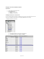
When the coommunications parameters have been se
et, the ould new SonNett network sho
look similar to this. In the
e SonNet Devvice Manager ould be window, thee receiver sho
shown in whhite. d “Unknown” are created aautomatically. Note Thee default foldeers “Receiver””, “Routers”, ““Sensors” and
thaat the “Discovver” button ha
as no functionnality in the So
onNet Device Manager. ng. Thee new SonNett network is now ready for commissionin
Commissioning a SonNet Network onNet networrk can be commissioned in 2 ways using tthe JACE drive
er; A So
1. An exissting networkk, where the receiver alreaady has child nodes joinedd to the receiver (for example, where the
e network ha s been comm
missioned usin
ng CMS or thhe receiver has been CE to another)) moved from one JAC
pletely new ne
etwork, wheree the receiverr has no child nodes 2. A comp
ork Commissioning an Exxisting Netwo
n existing netw
work, where rrouters and se
ensor end devvices (EDs) havve already joined the To ccommission an
receeiver’s networrk, requires ve
ery little manaagement. 1. Right‐click on the <SSonNetNetwoork> folder in the <Station
n\Config\Driveers> navigation tree, Actions> then <Set System Lock> select <A
2. Using the drop‐down list, select “Faalse” and then
n click OK. Page 25 of 47
The exissting networkk devices will a
appear in theiir respective ffolders. This m
may take seve ral minutes to
o compleete. hat when all e
existing nodess have appearred in the driver, the System
m Lock properrty be It is recommended th
set to TTrue. ew Network Commissioning a Ne
nsor end devicces (EDs) are ppresent on the To ccommission a new networkk, where no roouters and sen
receeiver’s networrk, or to add n
new devices too an existing n
network. 11.
Right‐click on the t
<Receivver> folder in the <Station\\Config\Driverrs\SonNetNettwork> naviggation tree, select <Actions>> then <Enablle Auto Comm
missioning Moode> 22.
Power up route
ers and EDss as require
ed (see “Commisssioning A Son
nNet System: S
Step‐By‐Step””, pages 68 ‐ 6
69) 33.
NB While W
the re
eceiver is in auto commiissioning mode it i s important N
NOT to use oth
her <Action> m
menu functions. Wait oined the network. until all ddevices have jo
44.
Right‐click on the t
<Receivver> folder in the <Station\\Config\Driverrs\SonNetNettwork> naviggation tree, select <Actions>> then <Disab
ble Auto Comm
missioning Moode> The new nettwork devicess will appear in thheir respective
e folders. nutes to This may takke several min
complete. Page 26 of 47
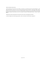
Configu
uring Networkk Devices Device Prefixes: own in the navv tree or the d
device’s prope
erty page, theey have default When SSonNet devicees are first sho
names w
which take th
he format of a prefix followeed by the MA
AC address of tthe device. e of device: Each prrefix denotes aa specific type
wn (i.e. the re
eceiver doesn’t have full infformation yett for the “U” denotess that the devvice is unknow
device) nd device (ED)) “S” denotess that the deviice is a batteryy powered en
“IO” denotees that the devvice is an RF‐I OM “R” denotess that the device is a routerr without senssing capabilities “X” denotess that the device is a routerr with sensing capabilities
There iss no prefix forr the receiver name. ommended that the device name is kept as the defaultt name. A useer friendly disp
play NB It is strongly reco
ured for each d
device. To sett a display nam
me, right‐click
k on the devicee and select ““Set name can be configu
Display Name” from the menu. Receiveer o the <Rece
eiver> folder in the <Statiion\Config\Drrivers\SonNettNetwork> na
avigation 1. Right‐click on tree, select <Views> then
n <Property Shheet> o the <Rece
eiver> folder in the <Statiion\Config\Drrivers\SonNettNetwork> na
avigation 2. Right‐click on tree, select <Actions> the
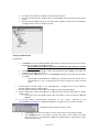
en <Get All Daata> 3. Note that so
oftware versio
on numbers, R
RF channel and receiver run
ntime are now
w all displayed
d. me, the RF chaannel and recceiver runtime
e values will bbe displayed as stale. 4. NB After a period of tim
mal, as these values are not updated unle
ess requested. This is norm
5. Note the staatus, last faultt cause and la st update tim
mes. 6. Note the staatus of the auto commissiooning feature.
e Receiver Prooperty Page The
Page 27 of 47
Routerss f
in thee <Station\Co
onfig\Drivers\S
SonNetNetwoork> navigatio
on tree, 1. Expand thee <Routers> folder select a router from the list, select <Vi ews> then <P
Property Sheett>. OT in auto com
mmissioning m
mode. 2. Ensure the rreceiver is NO
on the router and select <A
Actions> then <
<Get All Data>
> 3. Right‐click o
al router’s prooperty page A typica
1. Note that software version n
all numberrs and runttime are now displaye
ed. 2. NB After a period of time, t
all a
from m
measured values (such values apart as temp
perature) will be displayed as stale. This is normal, as oonly measured
d values are updated unless reequested. ult cause 3. Note the staatus, last fau
and last update timess. 4. Note the parrent of the router. es 5. Note the parrent LQI value
en a request ffor data is ma
ade to a NB Whe
router, the request should be prrocessed manently quickly, as the rout ers are perm
“awake””. However, the exact response period will w depend oon how manyy routers (if any) tthe request a nd reply have
e to pass through
h. Normally, thhe response iis within 30 seconds maximum
m. nts”, such as ““Temp” for thee measured te
emperature value, have deefault names. It is All the rrouter’s “poin
stronglyy recommend
ded that point names are keept as the deffault names. A
A user friendlyy display name
e can be configured for each p
point. To set a
a display namee, right‐click o
on the point in
n either the naav tree or the
e device’ss property sheeet and selectt “Set Display Name” from the menu. Config propertties, refer to tthe Router Acttions Menu onn page 52. To makke changes to the router’s C
Page 28 of 47
RF‐IOM
Ms n the <Stationn\Config\Drivvers\SonNetNe
etwork> naviggation tree, sselect an 1. Expand the <Io> folder in
m the list, sele
ect <Views> thhen <Propertyy Sheet>. RF‐IOM from
OT in auto com
mmissioning m
mode. 2. Ensure the rreceiver is NO
on an RF‐IOM and select <A
Actions> then <Get All Data> 3. Right‐click o
RF‐IOM’s propperty page, showing A typical R
the pointss expanded. N
that software version 1. Note numbers a
and runtime aare now all dissplayed. 2. NB After a per
N
riod of time, a
all values apart fro
om measure d values (ssuch as temperatu
ure) will be diisplayed as stale. This is normall, as only m
measured values are updated u
unless requestted. 3. Note N
the stattus, last fault cause and last up
pdate times. 4. Note the paren
N
nt of the RF‐IO
OM. 5. Note the paren
N
nt LQI values wing the input and A typical RF‐IOM’s propertty page, show
meters expannded. output configguration param
e the measure
ement intervaal. This pertain
ns to 1. Note
input measurrements only
2. The output config
guration param
meters are for the ese are writteen to the output output fallback values. The
he event that the RF‐IOM ggoes offline. channels in th
3. Note
e the input channel Types –– these reflectt the input jumperr settings. NB – it is importaant NOT to change the inout jum
mpers while th
he RF‐IOM is ppowered. 4. Note
e the low and high alarm leevels for each input channel. he 5. To set a new measurement inteerval, enter th
el in the appro
opriate box. required leve
6. To set high alarm,, low alarm orr COV values, enter ppropriate boox. the required level in the ap
es: The units ffor alarm leveels and COV arre 7. Note
dependent on the input ty
ype. For exampple, if an inpu
ut is set COV and alarm
m levels are also in to mA, then tthe units for C
mA. Page 29 of 47
Writingg Output RF‐IO
OM Values annels are wrritten, by defaault, every 5 m
minutes. How
wever, like inp
puts, the Values for the RF‐IOM output cha
output value cchanges by m
more than the SCV, the outputss can have a significant change value (SCCV) set. If the o
change is sent immediately. Each output channnel can be configured for a d
different SCV value, down tto 10mV steps. pand the outpput channel in
n the points list, then expaand Proxy Exttensions, To set tthe SCV for an output, exp
finally eexpand Write Parameters. E
Enter the requuired SCV in the Sig Change
e Trigger box ((highlighted a
above). M Fallback Values RF‐IOM
Fallbackk values are default values which are wr itten to the RF‐IOM outputt channels in tthe event thatt the RF‐
IOM go
oes offline (bu
ut remains pow
wered). This i s a safety me
echanism so th
hat plant conttrolled by the RF‐IOM outputss can be set to
o a “safe” valu
ue if the contrrol strategy caannot be upda
ated from the RF‐IOM. onfiguration P
Parameters annd enter the rrequired To set ffallback values for each outtput, expand tthe Output Co
values ffor each output. making change
es to the fallb ack values, it is essential to
o write the neew data to the device Importaant!!! After m
by rightt‐clicking the R
RF‐IOM and frrom the Actioon Menu seleccting Set Outp
put Configurattion. Page 30 of 47
RF‐IOM
M Input Configguration al determines how often th
he RF‐IOM sends it measu red input valu
ues. The The deffault measureement interva
default is 900 second
ds. Like EDs, iff an input val ue exceeds a configurable significant chhange value (SSCV), the V. measurred input value will be sent immediately.. Each input has its own SCV
perties, expannd the Input C
Configuration Params sectioon. To acceess input confiiguration prop
nd low alarm levels can also
o be set for eaach input. High an
hat the alarm levels are in the same un its as the input type. So, ffor example, iif Input 1 is se
et for 0‐
Note th
10Vdc tthe alarm leveels are also in Vdc. Similarlyy, SCV values aare in the sam
me units as thee input type. put is set as aa VFC type, the input value will be either 0 (OFF) or 1 (ON). Changees of input sta
ate for a If an inp
VFC inp
put are sent im
mmediately. making any ch
hanges to thee input configuration, it is e
essential to w
write the new
w data to Importaant!!! After m
the devvice by right‐clicking the RF‐‐IOM and from
m the Action Menu selectin
ng Set Input CConfiguration. ment interval be left at thee default value of 900 NB – It is strongly reecommended that the defaault measurem
unnecessary ra
adio traffic.
secondss to prevent u
Page 31 of 47
End Devvices (EDs) f
in thee <Station\Co
onfig\Drivers\S
SonNetNetwoork> navigatio
on tree, 1. Expand thee <Sensors> folder select a sensor from the llist, select <Viiews> then <P
Property Sheet>. OT in auto com
mmissioning m
mode. 2. Ensure the rreceiver is NO
on the sensor and select <A
Actions> then <Get All Data>A typical EDss property page 3. Right‐click o
ote that software version 1. No
numbers, battery leveel and runtim
me and device runttime are now all displayed.. 2. NB After a periiod of time, all values apart from measuredd values (ssuch as temperature) will be dissplayed as stale. This measured values are is normal,, as only m
updated un
nless requesteed. 3. No
ote the statuss, last fault ca
ause and last update
e times. 4. No
ote the parennt of the senso
or. 5. No
ote the parennt LQI values de to an NB When a request forr data is mad
equest is buuffered until the ED ED, the re
“wakes” to
o take and sennd its measurrements. Because off this, it may ttake some minutes to retrieve the requesteed data. The
e exact urement period willl depend onn the measu
interval time (default 900 seconds), how many routers (if any) thhe request and reply have to pass p
through and when in that transmissio
on cycle the reequest is mad
de. d temperaturre value, havee default nam
mes. It is All the sensor’s “poiints”, such ass “Temp” for the measured
ded that pointt names are keept as the deffault names. A
A user friendlyy display name can be stronglyy recommend
configured for each point. To set a display n ame, right‐click on the po
oint in either r the nav tree
e or the device’ss property sheeet and selectt “Set Display Name” from the menu. Page 32 of 47
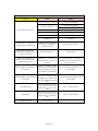
The VFC Activation Count Point The VFC Activation Count Point can be used as a “backup” to count VFC input True state activations, in the event that the ED or router can carry on counting input pulse even if the ED or router goes offline. When the ED or router comes back online, the VFC counts totalled in strategy can be compared with the total held in the VFC Activation Count Point, to be sure no pulses have been missed while the ED or router has been offline. The total held in the VFC Activation Count Point can be reset to 0 (see pages 53 and 55). To make changes to the EDs Config properties, refer to the Sensor Actions Menu on page 54. Page 33 of 47 Commissioning Multiple Networks on the Same Site It is quite a common requirement to need to commission several SonNet networks on the same site, for example one per floor in a multi‐storey building. To avoid the possibility of SonNet wireless nodes intended for one network appearing on another, 2 commissioning methods are available. Method 1: Pre‐commission each network away from site. This entails adding routers and EDs in the normal way to a receiver. If using an RF‐RXS, this can be done with the receiver connected to the RS‐232 port of a JACE. If using an RF‐RXS‐N, this can only be done with the receiver connected to a JACE option card slot. 1. Using Niagara AX or a web browser, set System Lock property to TRUE 2. Place the receiver into auto‐commissioning mode and power up all routers and EDs required on the receiver’s network to join. 3. When all devices have joined the network, take the receiver out of auto‐commissioning mode. 4. Perform a “get all data” request on all devices 5. Power off all routers and EDs associated with the receiver 6. Power off the receiver 7. Repeat this process for each receiver/network 8. Take all SonNet devices to site and install 9. Power up each receiver in turn together with its associated routers and EDs, and using Niagara AX or a web browser set the System lock property for each network to FALSE 10. All pre‐configured routers and EDs will join their respective receivers without the need to place any receiver into auto‐commissioning mode on site. Method 2: Commission each network individually on site. This entails adding routers and EDs in the normal way to a receiver. If using an RF‐RXS, this can be done with the receiver connected to the RS‐232 port of a JACE. If using an RF‐RXS‐N, this can only be done with the receiver connected to a JACE option card slot. 1. Using Niagara AX or a web browser, set System Lock to property FALSE 2. Place only one receiver at a time into auto‐commissioning mode and power up all routers and EDs required on the receiver’s network to join. 3. When all devices have joined the network, take the receiver out of auto‐commissioning mode. 4. Perform a “get all data” request on all devices NB It is important to ensure all receivers NOT being commissioned have auto‐commissioning disabled. Nodes which are already commissioned to an existing network must have reliable communications to that network to prevent them looking for other networks to join. Ensure all nodes on a commissioned network have a good link quality index (LQI) to their parents. In extreme cases, it may be prudent to temporarily power off “vulnerable” nodes while commissioning another network nearby. Page 34 of 47 Best Practise Points: 1. Always conduct a site survey, and ensure that if you plan to use an external extension aerial on the system receiver (for example, if the receiver is to be in a metal panel), you use the same external extension aerial on the SSK receiver for the survey. Document the survey thoroughly, and leave a copy on site. 2. When planning where routers and RF‐IOMs are going to be needed, plan for “redundancy”, i.e. what happens to all the EDs connected to a router if the router fails? Backup routers are worth considering. See pages 14 ‐ 15. 3. Don’t switch on EDs until they’re ready to be commissioned. If they’re powered on without a parent in range, they will eventually sleep to preserve battery life, only “waking” occasionally to scan for a parent. This may slow commissioning down. If an ED has been powered up for more than 20 minutes without a parent, power‐cycle it. Pressing the reset button on an ED DOESN’T reset the ED, it only resets the battery hours run time. 4. Generally speaking, wireless works best in a horizontal plane, so expect reduced signal strength if he receiver is on a different floor to the routers/RF‐IOMs/EDs. A good rule of thumb is to have the receiver on the same floor as its children, though this isn’t always the case. 5. 2.4GHz wireless signals don’t go through metal! Plan to circumvent metal obstructions where possible. 6. If the installation environment is one where obstructions are likely to change regularly (in a warehouse, for example!), try to conduct the site survey under a “worst‐case” scenario ‐ i.e. assume that at some point, there’s going to be an obstruction between the ED/router/RF‐IOM and its parent at some time. Simulate it, if possible. 7. When commissioning the installed system, turn the receiver on first, then all the routers and RF‐IOMs ‐ starting with “layer” nearest the receiver and working outwards. It’s worthwhile checking all the routers are OK in JACE driver before finally powering up the EDs. 8. When EDs first join a network, values such as hours run and battery hours run will not be displayed ‐ the values are shown as question marks. This is normal, these values need to be requested from the device (right‐click on device and select “Refresh Node Information”). 9. Remember that when a receiver scans all 16 channels for the best one, the channel chosen is the best where the receiver is. On “long” networks with several “layers” of routers, the channel chosen by the receiver may not always be the quietest at the far end of the network. When the installed network is finally formed, press the receiver reset button and ensure the network reforms properly. This will ensure that, in the event that the receiver needs to change channels (for example), it will work seamlessly. 10. As each network is commissioned, save the layout ‐ even if there isn’t a background graphic loaded. This is a good aid to quickly viewing network topology. Page 35 of 47 Trouble‐Shooter’s Guide System ED Symptom Cause Actions ED has not been authorized to the receiver Manually authorize ED to receiver or use auto‐commissioning No radio connection Check aerial on receiver Receiver not switched on Switch receiver on ED not switched on Switch ED on Incorrect battery polarity Check battery polarity Flat ED battery Change ED battery After switching on, if an ED cannot join a network after about 20 minutes, it will go into "sleep" mode to preserve battery life, only waking occasionally Power‐cycle the ED (switch it OFF and back ON) after ensuring all routers and the receiver are powered, and the routers have successfully joined the network ED appears in "Unknown" category when commissioning ED has joined network but has yet to pass configuration data to the receiver None ‐ normal operation ED stays in "Unknown" category when commissioning for more than 30 minutes ED hardware error Check ED options fitted (SP pot, thermistor, RH&T element) ED doesn't show hours run, firmware version, battery hours run or last update time Normal. To help preserve battery life, an ED doesn't send this information unless it is requested Request information using the "Get all data" method ED connects directly to the receiver, even though there's a router between them Normal. An ED will ALWAYS join a network using the least number of "hops" to the receiver. None ‐ normal operation. The ED will re‐join the network via the router if it loses its direct path to the receiver Only 12 EDs connect directly to my receiver Normal. The maximum number of directly connected EDs a receiver will allow is 12 If there are more than 12 EDs, at least one router must be used Only 8 EDs connect directly to my router Normal. The maximum number of directly connected EDs a router will allow is 8 If there are more than 8 EDs, at least one additional router must be added Normal. Updated ED information hasn’t been requested Request information using the "Refresh Node Information" method The battery hours run reset procedure wasn't carried out when the battery was replaced Power OFF the ED, press and hold the PCB button near the battery WHILE powering the ED ON After switching on, if an ED cannot join a network after about 20 minutes, it will go into "sleep" mode to preserve battery life, only waking occasionally Power‐cycle the ED (switch it OFF and back ON) after ensuring all routers and the receiver are powered, and the routers have successfully joined the network No connectivity to receiver I replaced the battery in my ED, but the battery hours run doesn't show as having been reset My ED was switched on in error before the receiver and routers, but hasn't joined the network Page 36 of 47 System Router Symptom Cause Actions Router has not been authorized to the receiver Manually authorize router to receiver or use auto‐commissioning No radio connection Check aerial on router Receiver not switched on Switch receiver on Router not switched on Switch router on Incorrect supply polarity Check supply polarity Router fuse Check router fuse is OK, replace if necessary Router appears in "Unknown" category when commissioning Router has joined network but has yet to pass configuration data to the receiver None ‐ normal operation Router stays in "Unknown" category when commissioning for more than 3 minutes Router hardware error Check router options fitted (thermistor, RH&T element) Router connects directly to the receiver, even though there's a router between them Normal. An router will ALWAYS join a network using the least number of "hops" to the receiver. None ‐ normal operation. The router will re‐join the network via the other router if it loses its direct path to the receiver Only 4 routers connect directly to my receiver Normal. The maximum number of directly connected routers a receiver will allow is 4, if there are 12 directly connected EDs None ‐ normal operation Only 8 routers connect directly to my router Normal. The maximum number of directly connected routers a router will allow is 8 if there are 8 directly connected EDs None ‐ normal operation No connectivity to receiver Check aerial on receiver Page 37 of 47 RF‐IOM Symptom Cause Actions RF‐IOM has not been authorized to the receiver Manually authorize RF‐IOM to receiver or use auto‐commissioning No radio connection Check aerial on RF‐IOM Receiver not switched on Switch receiver on RF‐IOM not switched on Switch RF‐IOM on Incorrect supply polarity Check supply polarity RF‐IOM fuse Check RF‐IOM fuse is OK, replace if necessary RF‐IOM appears in "Unknown" category when commissioning RF‐IOM has joined network but has yet to pass configuration data to the receiver None ‐ normal operation RF‐IOM stays in "Unknown" category when commissioning for more than 3 minutes RF‐IOM hardware error Check RF‐IOM RF‐IOM connects directly to the receiver, even though there's a RF‐IOM between them Normal. An RF‐IOM will ALWAYS join a network using the least number of "hops" to the receiver. None ‐ normal operation. The RF‐IOM will re‐join the network via the other RF‐IOM or router if it loses its direct path to the receiver Only 4 RF‐IOMs connect directly to my receiver Normal. The maximum number of directly connected RF‐IOMs a receiver will allow is 4, if there are 12 directly connected EDs At least one more RF‐IOM or router must be added Only 8 RF‐IOMs connect directly to my router Normal. The maximum number of directly connected RF‐IOMs a RF‐IOM or router will allow is 8 if there are 8 directly connected EDs At least one more RF‐IOM or router must be added Input LED flashing Normal. This denotes that the input has been set up and a VFC digital input, but is in the OFF state. None ‐ normal operation Input LED ON Normal. This denotes that the input has been set up and a VFC digital input, but is in the ON state. None ‐ normal operation Input type changed but the change is not shown RF‐IOM not reset after change has been made. Press the reset button on the RF‐IOM No connectivity to receiver Check aerial on receiver Page 38 of 47 System Receiver Symptom Cause Actions Check aerial and extension co‐ax (if fitted) LED D603 flashing once per second The receiver has found no children on the network If commissioning a network, ensure the receiver is in auto‐commissioning mode, or manually authorize new devices Ensure network devices are switched on and in range No power to receiver Check power to receiver Receiver not switched on Switch on receiver LED D603 on receiver not lit at all Receiver fuse LED D604 flashing occasionally Reception of network data Page 39 of 47 Check power supply polarity if using a DC supply Check receiver fuse is OK, replace if necessary None ‐ normal operation System Receiver RF‐RXS‐N Symptom Cause Actions Check aerial and extension co‐ax (if fitted) Network LED flashing once per second The receiver has found no children on the network If commissioning a network, ensure the receiver is in auto‐commissioning mode, or manually authorize new devices Ensure network devices are switched on and in range LEDs on receiver not lit at all No power to receiver Check power to JACE No communications SonNet driver configured for wrong JACE slot Configure SonNet driver for correct slot (see page 51) Data LED flashing occasionally Reception of network data None ‐ normal operation System Receiver RF‐RXS Symptom Cause Actions Check aerial and extension co‐ax (if fitted) Network LED flashing once per second The receiver has found no children on the network If commissioning a network, ensure the receiver is in auto‐commissioning mode, or manually authorize new devices Ensure network devices are switched on and in range No power to receiver Check power to receiver Receiver not switched on Switch on receiver LEDs on receiver not lit at all Receiver fuse Check power supply polarity if using a DC supply Check receiver fuse is OK, replace if necessary No communications via RS‐232 port USB port connected to PC Disconnect USB Data LED flashing occasionally Reception of network data None ‐ normal operation Page 40 of 47 Estimating Network Coverage in the Absence of a Site Survey The theoretical transmission distance that can be achieved between two wireless devices can be calculated from a few “key” parameters; Transmission power of device. This is the wireless device's transmission power and is typically measured in dBm. With greater transmission power, greater distances can be achieved. Receiver sensitivity of device. This is the wireless device's receiver sensitivity and is typically measured in dBm. With greater receiver sensitivity, the device is able to receive weaker signals, which means greater distances can be supported Antenna gain. The gain for an antenna is typically measured in dBi and basically indicates how much the signal is boosted by the antenna. Frequency. The frequency is typically measured in MHz or GHz and indicates which electromagnetic band is used for wireless communication. The formula for calculating the theoretical transmission distance is based on the Friis Transmission Equation for free space loss. The Friis Transmission Equation can be modified to give range, as follows: 10 /
41.88 ∗
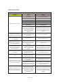
where: r = range in km Pt = Transmit power (dBm) Pr = receiver gain (dBm) Gt = transmitter aerial gain (dBi) Gr = receiver aerial gain (dBi) f = frequency (MHz) SonNet Routers, RF‐IOMs and Receivers
Frequency
2400 MHz
Tx power
10 dBm
Tx antenna gain
3 dBi
Rx antenna gain
3 dBi
Rx sensitivity
‐102 dBm
Theoretical Range (km)
7.9km
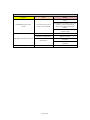
SonNet End Devices
Frequency
2400 MHz
Tx power
0 dBm
Tx antenna gain
1.2 dBi
Rx antenna gain
1.2 dBi
Rx sensitivity
‐96 dBm
Theoretical Range (km)
0.8km
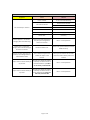
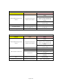
Note that this gives the theoretical transmission distance that can be achieved. Certainly, there are likely to be significant differences between the theoretical transmission distance and the actual results in the field, as these calculations are based on an unobstructed line‐of‐sight signal with no electronic interference. Page 41 of 47 However, the real world presents many variables that result in less “ideal” wireless performance, such as building obstructions and reflected signals. Therefore, it is always preferable to conduct a thorough site survey in order to determine what is actually happening to the wireless signals in the field. Before conducting a site survey, however, it may be helpful to evaluate the different options available for the wireless hardware. The formula provides a straightforward way to perform this evaluation and whether the desired transmission distance it can be achieved and so make an informed decision when selecting SonNet devices for different wireless applications. Attenuation Properties of Common Building Materials Building Material 2.4 GHz Attenuation Solid Wood Door 4.5cm 6 dB
Hollow Wood Door 4.5cm 4 dB
Interior Office Door w/Window 4.5cm /1.3cm
4 dB
Steel Fire/Exit Door 4.5cm 13 dB
Steel Fire/Exit Door 6.4cm 19 dB
Steel Rollup Door 3.8cm 11 dB
Brick 8.9cm 6 dB
Concrete Wall 45.7cm 18 dB
Cubical Wall (Fabric) 5.7m 18 dB
Exterior Concrete Wall 6.4cm 53 dB
Glass Divider 1.3cm 12 dB
Interior Hollow Wall 10.2cm
5 dB
Interior Hollow Wall 15.2cm 9 dB
Interior Solid Wall 12.7cm 14 dB
Marble 5.1cm 6 dB
Bullet‐Proof Glass 2.5cm 10 dB
Exterior Double Pane Coated Glass 2.5cm 13 dB
Exterior Single Pane Window 1.3cm 7 dB
Interior Office Window 2.5cm 3 dB
Safety Glass‐Wire 0.6cm 3 dB
Safety Glass‐Wire 2.5cm 13 dB
Page 42 of 47 Strategyy Tips evices to conntrol critical plant, it is always a
advisaable to add strategy 1. When usingg wireless de
safeguards tthat can take protective acttion in the eve
ent a wireless device loses communicatio
ons with its parent reeceiver. mple of this iss where an RFF‐IOM analoguue output is u
used to switch on an electriic heater battery. One An exam
of the kkey interlockin
ng safety featu
ures would bee to ensure th
hat the supply
y fan is runninng before allow
wing the heater tto be powered on. aken from, forr example, a Sontay PA‐930 air DP switcch or PM‐CSX
X current In this eexample, the fan status (ta
switch) is connected to a VFC input on RF‐IOM
M1 and the ou
utput from RF‐IOM2 is usedd to driver the
e heater battery. OM1 goes offlline, the conttrol strategy aand RF‐IOM2 no longer kn
nows if the faan is running,, so it is If RF‐IO
potentially unsafe to switch the he
eater battery oon. mple Niagara W
Workbench strategy below monitors the
e status of RF‐IOM1, and if it goes into a “Down” The sim
state (i..e. it goes offfline), it will cause c
the BoooleanSelect to
o output the vvalue held in the BooleanW
Writable modulee (FALSE in this case), ratherr than the norrmal control sstatus derives from strategyy. hat in the event that RF‐IOM
M2 goes offlinne, the output controlling tthe heater cann be configured to go Note th
a 0V using the appropriate fall‐bacck value settinng. F‐IOMs goes ooffline. This enssures that thee heater battery will be swittched off if eitther of the RF
measured valu
ues from an ED, E router or RF‐IOM are normally n
2. It should bee remembered that only m
sent, wheth
her by transmission time or significant ch
hange of value
e. ore, other parrameters, such
h as battery rruntime, parent LQI and de
evice runtime,, are NOT sen
nt unless Therefo
requestted. As simplee strategy to re
equest this infformation on a timed interval basis can bbe achieved. Add
d a “Dailyy Trigger” to the wirresheet, and sset its param
meters to a time t
of day (probably at a night, when there’s leaast activity). o the trigge
er, select <Liink Mark> frrom the Right‐click on menu, and then right‐click on the SSonNet device to be d select <Link from “trigger name”>. updated and
Page 43 of 47
<
Trigger>> on the trigger side Select <Fire and “Ge
et All Data” oon the SonNe
et device side. Other O
optionss are to sele
ect <Get Runtime> or <Get Paarent Lqi>, if these are specifically what iis required to be updated
d. Click the <O
OK> button. Specificc updates are preferable to <Get All Data>, a
as less netwoork traffic is ge
enerated and con
nsumes less baattery power in EDs. when the triggeer module fire
es, it will caus e a “Get All Data” command to be sent tto the SonNett device. Now, w
NB If seeveral SonNett devices are tto be updatedd this way, it iis strongly reccommended tthat the update times are stagggered by at leeast 15 minuttes, to avoid hheavy networkk traffic. n be used to o
on a wiresheett to show the status of a So
onNet device. 3. Strategy can
e wiresheet, w
with a Booleaan Writable. Link the <Dow
wn> slot to an input of Add a SStatusDemux module to the
the Boo
olean Writablee. device, select <Link Mark> ffrom the men
nu. Right‐click oon a SonNet d
Right‐click on the SStatusDemux module and sele
ect <Link from
m “device nam
me”> and select <
<Status> on thhe device side
e and “In Status” on the StatussDemux module side. Click the <OK> buttonn. If required, the faccets of the Boolean Writable can be channged to “OFFLLINE” for a True status, and ONLINE for a False status.
oleanChangeO
OfStateAlarmE
Ext> can A <Boo
be add
ded to the BBoolean Writa
able for alarming purposes. Page 44 of 47
4. Scaling a 4‐2
20mA RF‐IOM Input umeric Writab
bles are used tto set the uppper and lower ranges (for e
example, thee upper could be 40°C Two Nu
and thee lower 0°C, fo
or a temperatture sensor, o r the upper co
ould be 500Pa
a and the low
wer 0°C, for a p
pressure sensor). The examplee below uses a
an upper of 1000 and a lowe
er of 0, typical for an RH sennsor. put value from
m the RF‐IOM
M is linked to InA slot of the Subtract1 module, and the scaled output o
is The inp
availablle from the Ou
ut slot of the Scaled Currennt Value modu
ule. 5. Scaling a voltage RF‐IOM Input umeric Writab
bles are used tto set the uppper and lower ranges (for e
example, thee upper could be 40°C Two Nu
and thee lower 0°C, fo
or a temperatture sensor, o r the upper co
ould be 500Pa
a and the low
wer 0°C, for a p
pressure sensor). The examplee below uses a
an upper of 1000 and a lowe
er of 0, typical for an RH sennsor. put value from
m the RF‐IOM
M is linked to InA slot of the Multiply3 module, and the scaled output o
is The inp
availablle from the Ou
ut slot of the Scaled Voltagee Value modu
ule. Writable can be used A Boolean W
to offer scaliing for either 0‐5Vdc or 0‐10Vdc innputs. Page 45 of 47
6. Scaling a Resistive RFF‐IOM Input foor a 10K3A1 TThermistor he precision off the module facets should be set to 12. The 3 coefficcients, A, As a rulle, for greatesst accuracy, th
B and C
C are specificc to a 10K3A1 thermistor, but others could c
be used
d, according tto the Steinh
hart‐Hart method
d. The final Su
ubtract module can be omittted if °K is req
quired, rather than °C. 7.
Stale V
Values p
show
wn in the recceiver, route
er and ED pproperty she
eets are It will be noticed that some points suffixed {stale}. This is because
e the driver loooks for valu
ues to be updated with aa configurable time. If any vvalues aren’tt updated within this tim
me they are m
marked as sta
ale. It is im
mportant to remember that, t
under normal conditions, onlyy measured values are sent by devicess (routers orr EDs). Configuration parrameters and
d other data
a are not sennt unless req
quested, and will therefore eeventually be marked ass stale. A devicces measureed values will be markedd as stale if they are no
ot updated w
within the re
esponse timeou
ut period. Tyypically, an ED E has its d efault transmission time
e set to 9000 seconds, so
o if the respon
nse time is seet to 1 minutte (for exampple), the meaasured value
es will be maarked as stale
e. To ensure this doeesn’t happen, it is stronggly recomme
ended that th
he receiver rresponse tim
meout is set acccordingly; S
work> folde
er in the <Station\CConfig\Dri
ivers> Right‐click on the <SonNetNetw
navigation tree, then se
elect <Views
s> then <Property Sheet> P
> section, then expand the
e <Defaultt Policy> ssection. Expand thee <Tuning Policies
Set thhe <Stale Time> to
o 16 minutees (or a valu
ue that re
eflects longeest time a device may m require tto pass inforrmation to
o the driveer, which may m
be afffected not only by its default transmission time but by b how many m
routerss it may need to pa
ass its m
measurementt data th
hrough to gett to the rece
eiver. Page 46 of 47
Alarmss Alarmss can be set u
up using the <Alarm> paalette. Open the <Alarm> pa
alette and ddrag a new <Alarm Cl
lass> onto the Alarm Service Net Alarms”.. wiresheet. Call it “SonN
w <Console
eRecipient
t> onto the wiresheet and a link it too the SonNe
et alarm Drag a new
class.
ensions from
m the alarm palette ontto points w
which require
e alarm Next, dragg alarm exte
monitoringg. In the alarm extension s property sheet, set the
e alarm class to SonNet A
Alarms. Page 47 of 47
Alarmss Alarmss can be set u
up using the <Alarm> paalette. Open the <Alarm> pa
alette and ddrag a new <Alarm Cl
lass> onto the Alarm Service Net Alarms”.. wiresheet. Call it “SonN
w <Console
eRecipient
t> onto the wiresheet and a link it too the SonNe
et alarm Drag a new
class.
ensions from
m the alarm palette ontto points w
which require
e alarm Next, dragg alarm exte
monitoringg. In the alarm extension s property sheet, set the
e alarm class to SonNet A
Alarms. Page 83 of 83