1
4,460,957
1
2
More particularly, a three-state system bus 10, includ
ing address, data and control lines, interconnects the
basic components of the computer to provide for the
necessary transfer of address, data and control signals
among these components. The components include, for
SELF-FACING SERIAL KEYBOARD INTERFACE
FOR DATA PROCESSING SYSTEM
TECHNICAL FIELD
This invention relates generally to the ?eld of inter
face circuits for controlling two-way communication
between a keyboard and a data processing system and,
example, the central processing unit (CPU) 12, a dy
namic random access memory (RAM), a multiple chan
nel programmable direct memory access (DMA) con
troller 16, an interrupt controller 18, a read-only storage
more particularly, to a self-pacing interface which per
(ROS) 20, DI/DO’s 22, a display adapter 24, a disk
adapter 26 and a keyboard interface 28.
A cathode ray tube display device 30 may be con
nected by a cable 32 to the display adapter 24. A pair of
mits such communication using only two wires between
the interface and the keyboard.
BACKGROUND OF THE INVENTION
diskette drives 34 and 36 may be connected by a cable
Keyboard entry control circuits or interfaces are
38 to the disk adapter 26. A keyboard 40 is connected by
generally well-known in the prior art; however, they
a cable 42 to the keyboard interface 28.
In this preferred embodiment, the CPU 12 is an Intel
are quite complex and require more than two wires
between the keyboard and the interface, including, in
microprocessor 8088 which is fully disclosed in “The
addition to two wires for carrying clock and data sig
8086 Family User’s Manual, October 1979", published
nals, respectively, status lines for indicating the statuses 20 by
Intel Corporation, Santa Clara, California“. The
of the keyboard and central processing unit, respec
DMA controller is an Intel 8237 high performance
tively. Representative prior art keyboard entry control
programmable DMA controller also fully disclosed in
circuits and interfaces are disclosed in the following
US. Pat. Nos. 3,50l,749; 3,533,078;
4,044,398; 4,126,898 and 4,170,768.
the above Intel Corporation publication. RAM 14 is any
4,038,640;
conventional dynamic memory, such as a T] 4116. Inter
25 rupt controller 18 is an Intel 8259 chip. ROS 20 is also
conventional and may be a Mostek MK 3600, for exam
SUMMARY OF THE INVENTION
ple. DI/DO 22 is a digital input/digital output interface,
The present invention eliminates the need for the
complex keyboard interfaces of the prior art while, at
such as an Intel 8255A general purpose programmable
peripheral interface chip.
the same time, requiring only two wires between the 30 Keyboard interface 28 is the subject of the present
interface and the keyboard. The novel interface of the
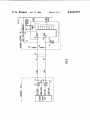
invention and is illustrated in detail in FIG. 2.
invention provides the following features:
Keyboard 40 is a programmable self-scanning serial
1. Keyboard data rate and clocking are not tied to any
speci?c clock frequency, and data may be sent at any
rate.
2. The only timing relationships required are set-up
and hold time required with respect to the rising edge of
the keyboard clock; thus, such relationships are easy to
implement in microcode.
3. Capability of supporting two-way communications
between the keyboard and central processing unit
(CPU) of the data processing system.
4. Full handshake and synchronous operation.
5. Relatively few components as compared to prior
ized keyboard which transmits a scan code of 8 series
data bits identi?ed in the various key positions. The
35 scan code also includes a start bit; thus, each serial scan
code is contained in a 9-bit frame headed by the start bit.
Also, in the preferred embodiment keyboard 40 is of the
capacitive matrix type and has 83 key positions. The
keyboard contains its own microprocessor, such as an
40 Intel 8048, and has an OUT CLOCK line, a SENSE
CLOCK line, an OUT DATA line and a SENSE
DATA line. Furthermore, each key is capable of
make/break and typamatic operation. The keyboard
contains self-scanning logic and interface controls
art interfaces.
45 which will support the protocol for keyboard interface
The presence of one or the other of two voltage
28, which protocol is described below.
levels on the two lines connecting the keyboard and
interface functions to control resetting of the keyboard
Keyboard 40, itself, forms no part of the present in
vention and its circuits and construction are found in
and transmission of keyboard data.
copending application Ser. No. 6l,7l9, ?led July 30,
For a better understanding of the present invention, 50 1979 and in the following US. Pat. Nos: 3,786,497;
together with other and further advantages and features
3,92l,l67; and 4,118,611; all of which are incorporated
thereof, reference is made to the following description
herein by reference.
taken in connection with the accompanying drawings,
In general, keyboard interface 28 is self-clocked or
the scope of the invention being pointed out in the ap
self-paced in that it is clocked or paced by the transmis
pended claims.
sion of the keyboard clock and data, completely inde
pendently of any other clock rates in the computer or
BRIEF DESCRIPTION OF THE DRAWINGS
data processing system. When either the system bus is
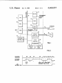
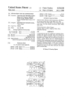
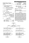
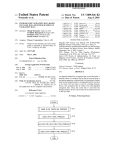
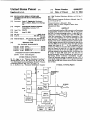
FIG. 1 is a block diagram of a data processing system
sending a reset command to the keyboard upon power
up or else the interface has not processed a previous
including the novel interface of the invention.
FIG. 2 is a logic block diagram illustrating the details
of the novel interface of the invention.
FIG. 3 is a timing diagram of the operation of the
scan code frame, the keyboard is prevented by its con
trol logic from transmitting data. When a complete scan
code frame has been stored in the interface, a latch is set
to generate an INTERRUPT REQUEST to the CPU
via the interrupt controller. When the INTERRUPT
interface illustrated in FIG. 2.
DESCRIPTION OF THE PREFERRED
EMBODIMENT
FIG. 1 is a block diagram ofa small computer or data
processor, such as a so-called personal computer.
65
REQUEST is granted and the data is transferred to the
CPU, the latch is cleared or reset to signal the keyboard
via its data line that another scan code may be transmit
ted to the interface. Only two lines are required in the