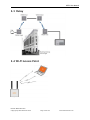
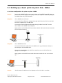
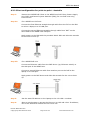
Download User Manual
Transcript
WESII Wireless Ethernet System WESII Series User Manual WESII User Manual About This Users’ Guide Intended Audience This manual is intended for people who want to configure any of the WESII Series. You will need a basic knowledge of TCP/IP and wireless topology. Related Documentation Quick Start Guide The Quick Start Guide is designed to help you get up and running. It contains basic information on setting up your individual WESII unit. Technical Specification The Technical specification is designed to provide you with all the technical specifications related to the WESII units. KBC Networks’ Website Please refer to www.kbcnetworks.com for additional support documentation and product certifications. Feedback We welcome all comments, questions and suggestions relating to our User Guides. Please contact us on: Technical Department KBC Networks Ltd 25691 Atlantic Ocean Drive Suite B3 Lake Forest CA 92630 Email: [email protected] Thank you Manual-WESII-Rev1403 Copyright © KBC Networks 2014 Page 1 of 140 www.kbcnetworks.com WESII User Manual Document Conventions Warnings and Notes These are how warnings and notes are shown is this Guide. !Warning! Warnings tell you about things that could harm you or your device. Note: Notes tell you other important information or recommendations. Example: Examples are provided to help make the WESII set up straight forward. Syntax Conventions The WESII units may be referred to as the ‘device’, the ‘product’ or the ‘system’ in this guide. <ENTER> denotes enter or return on your keyboard. <*****> denotes that you need to select that option. Manual-WESII-Rev1403 Copyright © KBC Networks 2014 Page 2 of 140 www.kbcnetworks.com WESII User Manual Safety Warnings !Warning! For your safety please read the following warning notices and instructions. Safety, Approvals and Regulatory Domain Information Safety Instruction For your protection, please read and observe all safety instructions before operating this system and keep this sheet and any additional instructions for future reference. Installation and Use OBSERVE WARNINGS: All warnings in the operating instructions should be carefully followed. Do not make any modifications to the WESII unit, Power Injection Module (PIM), or any other KBC Networks electronic device, as the unit(s) will no longer comply with legal regulations and therefore void its warranty. WATER AND MOISTURE: The WESII unit is weatherproof provided it is installed in accordance to the mounting details listed in section 2.4.3. However, further protection or housing is suggested for harsh environments, as moisture damage voids its warranty. The PIMs used in this system are NOT weatherproof. None of the modules in this system are waterproof and should never be submerged. Severe electrical shock, personal injury or damage to the equipment may result. POWER SOURCE: Connect the equipment to a power source only of the type described on the operating instructions or as marked on the equipment. Excessive or insufficient current or voltage can cause extended trouble-shooting or even damage that could negate its warranty. The power supply cable should not be modified/extended due to the ability to use up to 100m of power over Ethernet cable. In addition, Ethernet cable running from the PIM to the WEM should be kept separated from high-voltage cables and/or transformers. ATTACHMENTS: Use only KBC Networks’ supplied or recommended Power Injection Modules, Power Supplies, Cat5 Cables and weather seals and plugs. WHEN NOT IN USE: Unplug the power if the equipment is left unattended or unused for long periods of time or during lightning storms. REPLACEMENT PARTS: When replacement parts are required, use only replacement parts specified by KBC Networks. Unauthorized substitutions may result in damage to the system and could void the warranty. Manual-WESII-Rev1403 Copyright © KBC Networks 2014 Page 3 of 140 www.kbcnetworks.com WESII User Manual FCC Required Information Radio Frequency Interference Statement for Class B Digital Devices This equipment has been tested and found to comply with the limits for an intentional radiator, pursuant to Part 15, subpart C of the FCC Rules. This equipment generates, uses and can radiate radio frequency energy. This equipment generates, uses, and can radiate radio frequency energy. If not installed and used in accordance with the instructions, it may cause harmful interference to radio communications. The limits are designed to provide reasonable protection against such interference in residential situations. However, there is no guarantee that interference will not occur in a particular installation. If this equipment does cause interference to radio or television reception, which can be determined by turning the equipment on and off, the user is encouraged to try to correct the interference but on or more of the following measures: • • • • Re-orientate or relocate the receiving antenna of the affected radio or television. Increase the separation between the equipment and the affected receiver. Connect the equipment and the affected receiver to power outlets on separate circuits. Consult the dealer or an experienced radio/TV technician for assistance. Shielded cables must be used with this unit to ensure compliance with Class B FCC limits. Changes or modifications to this unit not expressly approved by the party responsible for compliance could void the user’s authority to operate the equipment. Changes or modifications not expressly approved by KBC could void the user’s authority to operate the equipment. FCC Power Output Restrictions The FCC does not require licensing to implement this device. License-free operation in the industrial, scientific and medical band is documented in FCC Rules Part 15.247. It is the responsibility of the individuals designing and implementing the radio system to ensure compliance with any pertinent FCC Rules and Regulations. This device must be professionally installed. Exposure to Radio Frequency Fields The WESII is designed to operate on the 5 GHz frequency band with up to 50 Watts EIRP maximum transmit power. This level of RF energy is above the Maximum Permissible Exposure (MPE) levels specified in FCC OET65:97-01. The following precautions must be taken during installation of this equipment: • • • • The installed antenna must not be located in a manner that allows exposure of the general population to the direct beam path of the antenna at a distance less than 20cm. Installation on towers, masts, or rooftops not accessible to the general population is recommended or alternatively mount the antenna in a manner that prevents any personnel from entering the area within 20cm from the front of the antenna. It is recommended that the installer place radio frequency hazard warnings signs on the barrier that prevents access to the antenna. During installation and alignment of the antenna, do not stand in front of the antenna assembly. During installation and alignment of the antenna, do not handle or touch the front of the antenna. Manual-WESII-Rev1403 Copyright © KBC Networks 2014 Page 4 of 140 www.kbcnetworks.com WESII User Manual These simple precautions must be taken to prevent general population and installation personnel from exposure to RF energy in excess of specified MPE levels. Industry Canada Restrictions IC ID# 7849A-N523ESD This Class A digital apparatus complies with Canadian ICES-003. To reduce potential radio interference to other users, the antenna type and its gain should be so chosen that the equivalent isotropically radiated power (E.I.R.P.) is not more than that permitted for successful communication. This device complies with Industry Canada license-exempt RSS standard(s). Operation is subject to the following two conditions: This device may not cause interference, and This device must accept any interference, including interference that may cause undesired operation of the device. Cet appareil numérique de la classe A est confrome à la norme NMB-003 Canada. Pour réduire le risque d’interférence aux autres utilisateurs, le type d’antenne et son gain doivent être choisies de façon que la puissance isotrope rayonnée équivalente (PIRE) ne dépasse pas ce qui est nécessaire pour une communication réussie. Cet appareil est conforme à la norme RSS Industrie Canada exempts de licence norme(s). Son fonctionnement est soumis aux deux conditions suivantes: 17 Compliance Cet appareil ne peut pas provoquer d’interférences et Cet appareil doit accepter toute interférence, y compris les interférences qui peuvent causer un mauvais fonctionnement du dispositif. RF Exposure Warning The antennas used for this transmitter must be installed to provide a separation distance of at least 37.2 cm from all persons and must not be located or operating in conjunction with any other antenna or transmitter. Les antennes utilisées pour ce transmetteur doivent être installé en considérant une distance de séparation de toute personnes d'au moins 37.2 cm et ne doivent pas être localisé ou utilisé en conflit avec tout autre antenne ou transmetteur. Manual-WESII-Rev1403 Copyright © KBC Networks 2014 Page 5 of 140 www.kbcnetworks.com WESII User Manual CE Regulatory Statement Class B ITE: This is a Class B product. In a domestic environment this product may cause radio interference in which case the user may be required to take adequate measures. Declaration of Conformity: KBC declares the following: Product Name: WESII Model No.: 802.11n Station conforms to the following Product Standards: This device complies with the Electromagnetic Compatibility Directive (89/336/EEC) issued by the Commission of the European Community. Compliance with this directive implies conformity to the following European Norms (in brackets are the equivalent international standards.) Electromagnetic Interference (Conduction and Radiation): EN 55022 (CISPR 22) Electromagnetic Immunity: EN 55024 (IEC61000-4-2, 3, 4, 5, 6, 8, 11) Low Voltage Directive: EN 60 950: 1992+A1: 1993+A2: 1993+A3: 1995+A4: 1996+A11: 1997. CE Mark: following the provisions of the EC directive. KBC also declares that: The wireless card in this product complies with the R&TTE Directive (1999/5/EC) issued by the Commission of the European Community. Compliance with this directive implies conformity to the following: EMC Standards: CE: EN 300 328-2, EN 300 826 (EN 301 489-17) EN 301 893. CE marking on this product represents the product is in compliance with all directives that are applicable to it. This equipment may be operated in the following countries: Great Britain and Northern Ireland, Austria, Belgium, Denmark, Finland, France, Germany, Ireland, Italy, Netherlands, Norway, Portugal, Romania, Switzerland, Sweden Installer Compliance Responsibility Devices must be professionally installed and it is the professional installer's responsibility to make sure the device is operated within local country regulatory requirements. Dynamic Frequency Selection (DFS) & Transmit Power Control (TPC): DFS and TPC are requirements of the ETSI standard EN301 893 V1.5.1, the European Union’s harmonized radio standard for unlicensed devices operating in the 5150 – 5350 MHz and 5470 – 5725 MHz frequency bands. Radar detection is required when operating on channels whose nominal bandwidth falls partly or completely within the frequency ranges 5250 MHz to 5350 MHz or 5470 MHz to 5725 MHz. In addition devices using the 5600 – 5650 MHz band are subject to a 10 minute Channel Availability Check (CAC). The following table shows how this can affect connection times for certain frequencies: Manual-WESII-Rev1403 Copyright © KBC Networks 2014 Page 6 of 140 www.kbcnetworks.com WESII User Manual Frequency (MHz) Channel Bandwidth 5MHz 10MHz 20MHz 20/40MHz 5500 2 mins 2 mins 2 mins 2 mins 5505 2 mins 5510 2 mins 5515 2 mins 5520 2 mins 5525 2 mins 5530 2 mins 5535 2 mins 5540 2 mins 5545 2 mins 5550 2 mins 5555 2 mins 5560 2 mins 5565 2 mins 5570 2 mins 5575 2 mins 5580 2 mins 5585 2 mins 5590 2 mins 5595 2 mins 5600 10 mins 5605 10 mins 5610 10 mins 5615 10 mins 5620 10 mins 5625 10 mins 5630 10 mins 5635 10 mins 5640 10 mins 5645 10 mins 5650 10 mins 5655 2 mins 5660 2 mins 5665 2 mins 5670 2 mins 5675 2 mins 5680 2 mins 5685 2 mins 5690 2 mins 5695 2 mins 5700 2 mins Manual-WESII-Rev1403 Copyright © KBC Networks 2014 2 mins 2 mins 2 mins 2 mins 2 mins 2 mins 2 mins 2 mins 2 mins 2 mins 2 mins 2 mins 2 mins 10 mins 2 mins 10 mins 10 mins 10 mins 10 mins 10 mins 10 mins 10 mins 10 mins 10 mins 10 mins 2 mins 2 mins 2 mins 2 mins 2 mins 2 mins 2 mins 2 mins Page 7 of 140 2 mins www.kbcnetworks.com WESII User Manual Environmental Restrictions of Wireless Devices KBC products are engineered to the highest standards and designed to work in a variety of wireless applications and environments. A wireless environment includes the site in which the product is installed, the installation including power and cabling as well as any extra materials that might be necessary to complete the wireless project. Due to the fact that environments and installations differ from site to site, KBC cannot control the variables required to ensure an ideal environment. Therefore, it is not possible to guarantee a successful application based on a drawing, application note, distance calculation, quote or other type of material that KBC may provide. Should a quote, drawing, etc. be made available, it is based on the performance of the WESII product in an ideal environment with clear line-of-sight, absence of 5 GHz interference and/or frequency multi-path reflection. Therefore, KBC cannot be held responsible should the products not operate as desired or should additional products be required to complete a project. In addition, should a particular environment restrict the usage of the WESII in any way, KBC offers a thirty (30) day return policy from date of shipment to the original purchaser if goods are returned in an ‘as new’ condition. Manual-WESII-Rev1403 Copyright © KBC Networks 2014 Page 8 of 140 www.kbcnetworks.com WESII User Manual RoHS/WEEE Compliance Statement European Directive 2002/96/EC requires that the equipment bearing this symbol on the product and/or its packaging must not be disposed of with unsorted municipal waste. The symbol indicates that this product should be disposed of separately from regular household waste streams. It is your responsibility to dispose of this and other electric and electronic equipment via designated collection facilities appointed by the government or local authorities. Correct disposal and recycling will help prevent potential negative consequences to the environment and human health. For more detailed information about the disposal of your old equipment, please contact your local authorities, waste disposal service, or the shop where you purchased the product. Instruction of Disassembly Note: disassembling or opening of the WESII unit voids warranty. Instruction of Disassembly of KBC Product (For EU Directive 2002/95/EECWEEE) Tools required: No. 1 Phillips screwdriver No. 2 Phillips screwdriver Steps for disassembly: Remove Serial Label adhesive Remove cover screws attaching top cover to radio module cavity. Remove tightening screws for printed circuit board (PCB). Take out all PCBs. Note: When a product reaches the end of its life – return to KBC. Manual-WESII-Rev1403 Copyright © KBC Networks 2014 Page 9 of 140 www.kbcnetworks.com WESII User Manual General Public License Statement You may have received from KBC Networks products that contained – in part – free software (software licensed in a way that ensures your freedom to run, copy, distribute, study, change and improve the software). Such products include the WESII Series of products. As part of these products, KBC Networks may have distributed to you hardware and/or software that contained a version of free software programs developed by the Free Software Foundation, a separate not-for-profit organization without any affiliation to KBC Networks. See http://www.gnu.org/philosophy/free-sw.html for more details. If KBC Networks distributed any portions of these free software programs to you, you were granted a license to that software under the terms of either the GNU General Public License or GNU Lesser General Public License (“License”, copies of which are available from http://www.gnu.org/licenses/licenses.html). The Licenses allow you to freely copy, modify and redistribute that software without any other statement or documentation from us. For at least one (1) year from the date of distribution of the applicable product or software, KBC Networks will provide to anyone who contacts us at the contact information provided below, for a charge of no more than our cost of physically performing source code distribution, a complete machine-readable copy of the complete corresponding source code for the free software programs used in the version of the programs that we distribute to you. The cost will be free if the delivery medium of the machine-readable copy is through the Internet. Contact information: Email: Tel: Address: [email protected] 949.297.4930 25691 Atlantic Ocean Drive Lake Forest, CA 92630 We do ask for your understanding regarding expected delivery timelines: We will reply within 7 working days once the request has been made through email/telephone. The default version sent will be the latest that we used in the firmware/programs. Note: it may take longer if an older version is requested. The waiting time will not exceed 2 weeks. Manual-WESII-Rev1403 Copyright © KBC Networks 2014 Page 10 of 140 www.kbcnetworks.com WESII User Manual TABLE OF CONTENTS ABOUT THIS USERS GUIDE…………………………………………………………………………………………1 Intended Audience…………………………………………………………………………………………………………………………..….…….…1 Related Documentation…………………………………………………………………………………………………………………..……………1 DOCUMENT CONVENTIONS……………………………………………………………………………………….2 Warnings and Notes………………………………………………………………………………………………………………………...………….2 Syntax Conventions ……………………………………………………………………………………………………………………………………..2 SAFETY WARNINGS……………………………………………………………………………………………………3 SAFETY, APPPROVALS AND REGULATORY DOMAIN INFORMATION………………………….3 Safety Instruction………………………………………………………………………………………………………………………….…………….3 FCC Required Information……………………………………………………………………………………………….…………………………..4 Industry Canada Restrictions……………………………………………………………………………………………………….……………...5 CE Regulatory Statement…………………………………………………………………………………………………….………………………6 Environmental Restrictions of Wireless Devices…………………………………………………………………….…………………….8 ROHS/WEEE COMPLIANCE STATEMENT…………………………………………………………………….9 Instructions of Disassembly……………………………………………………………………………………………………..…………………..9 GENERAL PUBLIC LICENSE STATEMENT………………………………………………………………….10 1 OVERVIEW…..………………………………………………………………….……………………………13 1.1 Introduction………………………………………………………………………………………………………………………………………13 1.2 General Technical Specification…………………………………………………………………………..…………………………….14 2 TYPICAL CONFIGURATIONS…………………………………………………….……………..…..16 2.1 2.2 2.3 2.4 2.5 3 Point-to-point…………………………………………………………………………………………………………………………………….16 Point-to-multipoint…………………………………………………………………………………………………………………………….17 Relay………………………………………………………………………………………………………………………………………………….18 Wi-Fi Access Point………………………………………………………………………………………………………………………………18 Mixed systems – WESII & MeshII………………………………………………………………………………………………….…...19 ANTENNA OPTIONS……………………………………………………………………………………….20 3.1 Omni-directional antennas………………………………………………………………………………………………………………..20 3.2 Integrated directional antenna options……………………………………………………………………………………………..20 3.3 External directional patch antenna options………………………………………………………………………………………..21 4 POINT-TO-POINT KITS…………………………………….……………………….………………….22 5 MOUNTING INSTRUCTIONS…………………………………………………………………………..23 5.1 Pole and wall-mount for integrated directional WESII units………………………………………………………………23 Manual-WESII-Rev1403 Copyright © KBC Networks 2014 Page 11 of 140 www.kbcnetworks.com WESII User Manual 6 CONNECTIONS……………………………………………………………………………….……………..25 6.1 Physical Connections…………………..…………………………………………………….……………………………………………..25 6.2 Power Connections…………………………………………………………………………………………………………………………..26 7 LED STATUS……………………………………………….………………………………………………….28 7.1 Non-PoE WESII……………………………………………………………………………………………………………….…………………28 7.2 PoE WESII……………………………………………………………….………………………………………………………………………..28 8 CABLE ASSEMBLY………………………………………………………………………………………….29 8.1 Strain Relief Assembly…………………………………………………………………..……………………..……….………………….29 8.2 Configuring the Cable……………………………………………………………………………………………………………………….29 9 SETTING UP A BASIC LINK…………………………………………………………………………..31 9.1 9.2 9.3 9.4 9.5 9.6 10 Setting up a basic point-to-point link – United States & Canada…………………………………………….………..32 Setting up a basic point-to-point link – EMEA………………………….…………………………………………….………..40 Setting up a basic point-to-point link – Australia…………………….……………………………….…………….………..53 Setting up a basic point-to-multipoint link – United States & Canada………………………………...….………..61 Setting up a basic point-to-multipoint link – EMEA………………………….…………………………………….………..70 Setting up a basic point-to-point link – Australia…………………….……………………………………….…….………..83 INSTALLING ON A SITE………………………………………………………………………………….91 10.1 10.2 10.3 10.4 10.5 10.6 11 Line-of-sight………………………………………………………………………………………………………………………………..…...91 Spacing required when mounting WESII units…………………………………………………………………………………..93 Cable lengths when installing WESII units…………………………………………………………………………….……………94 Aligning the WESII units……………………………………………………………………………………….……………………………95 Configuring IP addresses on a site…………………………………………………………………………………………………….95 Replacing/adding a WESII Module from/to the existing application………………………………………………….96 GRAPHICAL USER INTERFACE………………………………………………………………………97 11.1 Connecting to the WESII GUI using a PC……………………………………………………..…………………..………………..97 11.2 WESII Menu Options………………………………………………………………………………………………………..……………….99 12 TROUBLESHOOTING……………………………………………………………………………………136 12.1 12.2 12.3 12.4 12.5 13 Visual Inspection……………………………………………………………………………………………..……………………………..136 Test Cable Connections…………………………………………………………………………………………………………………...136 GUI Tools…………………………………………………………………………………………………………………………………………136 Hard reset to defaults……………………………………………………………………………………………………………………..137 Contact KBC Technical Assistance…………………………………………………………………………………………………….138 WARRANTY………………………………………………………………………………………………….139 Manual-WESII-Rev1403 Copyright © KBC Networks 2014 Page 12 of 140 www.kbcnetworks.com WESII User Manual 1. Overview 1.1 Introduction This manual covers all the functions of the products that form KBC Networks’ WESII Series. The WESII Wireless Ethernet System is a wireless transmission system that provides a cable less transmission path for an Ethernet channel. They are designed for use in a wide range of operating temperatures in non-environmentally conditioned, outdoor applications. The primary function of the system is to replace Ethernet cables where it is not practical or cost-effective or where it is beyond distance limitations. WESII has been specifically designed to transmit constant streaming video but can also be used to send and receive standard Ethernet data packets or to operate as a WiFi Access Point. The units can be configured as a long range point-to-point wireless bridge or as a point-to-multipoint receiving antenna communicating to numerous transmitting Client/Station devices. This manual covers all operations and functions of the point-topoint and point-to-multipoint systems. 1.1.1. WESII The KBC WESII Series is a wireless transmission system that operates in the license free 2.4GHz & 5GHz bands and also in the 4.9GHz Public Safety band (only available in the US). The units are available as PoE or non-PoE with a range of antennas to suit applications. The units will support throughput of up to 99Mbps due to MIMO technology. Manual-WESII-Rev1403 Copyright © KBC Networks 2014 Page 13 of 140 www.kbcnetworks.com WESII User Manual General Technical Specification WESII Specification Standards IEEE Standards IEEE IEEE IEEE IEEE IEEE IEEE IEEE IEEE IEEE IEEE 802.3 10BASE-T 802.3u 100BASE-TX 802.3x Full Duplex 802.11a 5GHz 802.11b 2.4GHz 802.11g 2.4GHz 802.11y 4.9GHz US Public Safety 802.11n MIMO 802.11h ETSI DFS & TPC 802.3af Radio Frequency (MHz) Frequency Operation Power Output Channel Capacity Modulation Antennas 2dBi/5dBi (2.4GHz/4.9GHz & 5GHz) 9dBi (4.9GHz & 5GHz) 11dBi (2.4GHz) 17dBi (4.9GHz & 5GHz) 1 USA & Canada: 2412 - 2472 4940 - 4990 5745 – 5825 Europe: 2412 - 2472 5500 - 5700 Auto-select User static selectable Dynamic Frequency Selection (ETSI DFS) 23dBm max1 Transmit Power Control (ETSI TPC) Selectable 5, 20 or 40MHz OFDM Omni-directional Directional integrated patch Dual polarization Beamwidth: Azimuth: Horizontal 65°, Vertical 65° Elevation: Horizontal 33°, Vertical 33° Directional integrated patch Dual polarization Beamwidth Azimuth: Horizontal 56°, Vertical 62° Elevation: Horizontal 38°, Vertical 26° Directional integrated patch Dual polarization Beamwidth: Azimuth: Horizontal 30°, Vertical 33° Elevation: Horizontal 17°, Vertical 17° Territory specific. Manual-WESII-Rev1403 Copyright © KBC Networks 2014 Page 14 of 140 www.kbcnetworks.com WESII User Manual System Data throughput2 (max values – limited by 10/100 port) Latency Power HT5 17Mbps < 10 mS Power method (non-PoE WESII) Power method (PoE WESII) PoE cable spec Mechanical Casing Dimensions (Patch L x W x D) Weight Installation Environmental Operating Temperature Storage Temperature Operating Humidity Connectors 10/100 Electrical Approvals FCC Part 15 subpart C IC ID# 7849A-N523ESD CE EN 55024 (IEC61000-4-2,3,4,5,6,8,11) EN 60 950: 1992+A1; 1993+A2; 1995+A4; 1996+A1; 1997 EN 300 328-2 EN 300 826 EN 301 489-17 EN 301 893 R&TT Directive (1999/5/EC) HT40 99Mbps 24Vdc, 500mA Reverse voltage protected Passive PoE IEEE 802.3af (PD) 100m on 24AWG Cat5/5e/6/6e Power input (supplied by PIM) EN 55022 (CISPR 22) HT20 99Mbps IP66 245mm x 245mm x 76mm 9.625” x 9.625” x 3” 420g 15oz Wall-mount or pole-mount -40° ~ +74°C / -40° ~ +165°F -40° ~ +90°C / -40° ~ +194°F 5% to 95% non-condensing 1 x RJ45 Class B Class B Electromagnetic Immunity Electromagnetic Interference (Conduction and Radiation) Low Voltage Directive 2 Assumes an ideal environment with maximum signal rates & within receive sensitivity specification. Manual-WESII-Rev1403 Copyright © KBC Networks 2014 Page 15 of 140 www.kbcnetworks.com WESII User Manual 2. Typical Configurations The WESII units are available to work in the following configurations: • • • • • Point-to-point Point-to-multipoint Relay Wi-Fi Access Point Mixed systems 2.1 Point-to-Point 2.1.1 Non-PoE WESII 2.1.2 PoE WESII Manual-WESII-Rev1403 Copyright © KBC Networks 2014 Page 16 of 140 www.kbcnetworks.com WESII User Manual 2.2 Point-to-multipoint 2.2.1. Non-PoE WESII 2.2.2. PoE WESII Manual-WESII-Rev1403 Copyright © KBC Networks 2014 Page 17 of 140 www.kbcnetworks.com WESII User Manual 2.3 Relay 2.4 Wi-Fi Access Point Manual-WESII-Rev1403 Copyright © KBC Networks 2014 Page 18 of 140 www.kbcnetworks.com WESII User Manual 2.5 Mixed systems – WESII & MeshII Manual-WESII-Rev1403 Copyright © KBC Networks 2014 Page 19 of 140 www.kbcnetworks.com WESII User Manual 3. Antenna Options The WESII units are available with the following antennas: • • • • • • • 2dBi/5dBi dual rated omni-directional antenna for 2.4GHz/4.9GHz & 5GHz operation 9dBi integral patch antenna for 4.9GHz & 5GHz operation 11dBi integral patch antenna for 2.4GHz operation 17dBi integral patch antenna 4.9GHz 5GHz operation 9dBi external patch antenna for 4.9GHz & 5GHz operation 11dBi external patch antenna for 2.4GHz operation 17dBi external patch antenna for 4.9GHz & 5GHz operation 3.1 Omni-directional options 3.1.1 2dBi/5dBi This is a dual frequency rated omni-directional antenna for 2.4GHz, 4.9GHz & 5GHz operation. At 2.4GHz the antenna has a gain of 2dBi and at 4.9GHz & 5GHz the antenna has a gain of 5dBi. The beamwidth of the antenna is 360°. 3.2 Integrated directional patch antenna options 3.2.1 9dBi This is an integral directional patch antenna option for 4.9GHz & 5GHz operation. The antenna is dual polarized. The beamwidth is: Azimuth: Horizontal 65°, Vertical 65° Elevation: Horizontal 33°, Vertical 33° 3.2.2 11dBi This is an integral directional patch antenna option for 2.4GHz operation. The antenna is dual polarized. The beamwidth is: Azimuth: Horizontal 56°, Vertical 62° Elevation: Horizontal 38°, Vertical 26° Manual-WESII-Rev1403 Copyright © KBC Networks 2014 Page 20 of 140 www.kbcnetworks.com WESII User Manual 3.2.3 17dBi This is an integral directional patch antenna option for 4.9GHz & 5GHz operation. The antenna is dual polarized. The beamwidth is: Azimuth: Horizontal 30°, Vertical 33° Elevation: Horizontal 17°, Vertical 17° 3.3 External directional patch antenna options External antennas can be attached to the antenna ports on the external antenna chassis and are provided with 2 x 1m cables. See section 6.1.2. 3.3.1 9dBi This is an external directional patch antenna option for 4.9GHz & 5GHz operation, part number PAT5M-9. The antenna is supplied as a separate unit that contains 1 x 9dBi patch antenna and 2 x 1m cables. The antenna is dual polarized. The beamwidth is: Azimuth: Horizontal 65°, Vertical 65° Elevation: Horizontal 33°, Vertical 33° 3.3.2 11dBi This is an external directional patch antenna option for 2.4GHz operation, part number PAT2M. The antenna is supplied as a separate unit that contains 1 x 11dBi patch antenna and 2 x 1m cables. The antenna is dual polarized. The beamwidth is: Azimuth: Horizontal 56°, Vertical 62° Elevation: Horizontal 38°, Vertical 26° 3.3.3 17dBi This is an external directional patch antenna option for 4.9GHz & 5GHz operation, part number PAT5M. The antenna is supplied as a separate unit that contains 1 x 17dBi patch antenna and 2 x 1m cables. The antenna is dual polarized. The beamwidth is: Azimuth: Horizontal 30°, Vertical 33° Elevation: Horizontal 17°, Vertical 17° Manual-WESII-Rev1403 Copyright © KBC Networks 2014 Page 21 of 140 www.kbcnetworks.com WESII User Manual 4. Point-to-point Kits There are a number of WESII point-to-point kits that are available, details are below: Part number Description Contents WESII-KT 5GHz, point-to-point 17dBi kit 2 x 5GHz WESII 17dBi point-topoint units WESII-KT-9 5GHz, point-to-point 9dBi kit 2 x 5GHz WESII 9dBi point-topoint units WESII-KT-POE 5GHz, point-to-point kit with WESII PoE units 2 x 5GHz WESII 17dBi PoE point-to-point units WESII-KT-49 4.9GHz, point-to-point kit 2 x 4.9GHz WESII point-to-point units WESII-KT-49P 4.9GHz, point-to-point kit with WESII PoE units 2 x 4.9GHz WESII PoE point-topoint units WESII-KT-ED 5GHz, point-to-point kit with encoder & decoder 2 x 5GHz WESII point-to-point units + KBC encoder & decoder WESII-KT-P5 5GHz, point-to-point kit with 5 port PoE switch & narrow temperature range PSU 2 x 5GHz WESII point-to-point units + ESUL5P-D + DRP-12048 WESII-KT-P5T 5GHz, point-to-point kit with 5 port PoE switch & extended temperature range PSU 2 x 5GHz WESII point-to-point units + ESUL5P-D + SDR-12048 WESII-KT-P8 5GHz, point-to-point kit with 5 port PoE switch & narrow temperature range PSU 2 x 5GHz WESII point-to-point units + ESUG8P-D + DRP-48048 WESII-KT-P8T 5GHz, point-to-point kit with 5 port PoE switch & extended temperature range PSU 2 x 5GHz WESII point-to-point units + ESUG8P-D + SDR-48048 Manual-WESII-Rev1403 Copyright © KBC Networks 2014 Page 22 of 140 www.kbcnetworks.com WESII User Manual 5. Mounting Instructions WESII units are sold with all necessary mounting brackets and screws for installation on 76mm/3” diameter pole or wall mount. Note: This equipment must be installed in accordance with the instructions found in this manual. The orientation must be as depicted below. Failure to comply with these instructions will invalidate warranty. 5.1 Pole and wall-mount for WESII units Manual-WESII-Rev1403 Copyright © KBC Networks 2014 Page 23 of 140 www.kbcnetworks.com WESII User Manual Qty Description 1 Bracket body 1 Pole clamp bracket 1 Connecting piece 1 1 Connecting piece 2 1 50mm, 1.98” long ¼” hex bolt 3 ¼” hex nuts 1 27mm, 1.06” long ¼” hex bolt 3 Flat washers 15mm, 0.59” 3 Locking washers 10mm, 0.39” long 1 U bolt 4 ¼-20 lock washers • • • • • • • • • • Remove all packaging material Remove 50mm bolt, flat washer, locking washer and hex nut. Mount back plate to front WESII assembly plate. Replace flat washer, locking washer and hex nut. Remove ‘U’ shaped bolt. Bolt the unit to the pole. Up/Down Alignment offers one position when using the pre-fabricated channel lock grooves on the swivel brackets. Directional antennas may require additional up/down alignment angles than those allowed on the pre-fabricated grooves. To achieve different angles, remove the 50mm Hex bolt. Insert the longer bolt and add the star washer. Re-connect and tighten. Position the WESII unit to face the WESII unit at the other end of the link. Carry out the alignment process – see Section 10.4 for instructions and Section 7 for LED status information. When in the best position, tighten. Manual-WESII-Rev1403 Copyright © KBC Networks 2014 Page 24 of 140 www.kbcnetworks.com WESII User Manual 6. Connections 6.1 Physical Connections 6.1.1 Integrated Patch Antenna Chassis 1. Patch antenna cover 2. Serial number label 3. Internal RF module enclosure 4. Status LEDs 5. LAN port (RJ45) 6. Mounting block 7. Reset to default button 3 1. Patch an tenn a cover 1 7 Front view Rear view 6.1.2 External Antenna Chassis 1. Antenna ports, attach screw down omni-directional antennas (for directional antennas, connect jumper LMR-200 cable) 2. Serial number label 3. Internal RF module enclosure 4. Status LEDs 5. LAN port (RJ-45) 6. Mounting block 7. Reset to default button 2 1. Patch antenna cover 7 Rear view Note: See Section 11.2.2.3 for details of how to carry out a hard reset to default settings. Manual-WESII-Rev1403 Copyright © KBC Networks 2014 Page 25 of 140 www.kbcnetworks.com WESII User Manual 6.2 Power Connections WESII units are available as either PoE or non-PoE units. 6.2.1 Power Injector Module for the non-PoE WESII Non-PoE WESII units are supplied with a mid-span Power Injector Module (PIM) and a standard 24Vdc, 500mA Power Supply Unit. Note: The Power Injector Modules are not weatherproof units and must be protected from moisture. Power – Power supply input OUT – Connect to the WESII unit IN – Connect to the Ethernet device For extreme temperature conditions there is also a KBC Networks Industrial DIN Rail power supply available, part number MDR-20-24. These units provide 24W at 24Vdc. These units need to be purchased separately, for further details please contact KBC Networks. Note: KBC Networks’ WESII non-PoE units are mid-span compliant and must be powered using the supplied KBC Networks’ Power Injection Module. Manual-WESII-Rev1403 Copyright © KBC Networks 2014 Page 26 of 140 www.kbcnetworks.com WESII User Manual 6.2.2 Power for the PoE WESII The PoE WESII units are IEEE 802.3af Powered Devices (PD) ie. they are powered from a Power Sourcing Equipment (PSE) such as an Ethernet switch which provides power on the Ethernet cable. There are a number of different Ethernet switches options with PoE available from KBC Networks, these can be purchased separately. Please contact KBC Networks for further information. Manual-WESII-Rev1403 Copyright © KBC Networks 2014 Page 27 of 140 www.kbcnetworks.com WESII User Manual 7. LED Status 7.1 Non-PoE WESII 1 2 3 4 5 6 Status/Signal Strength Indicator – 40 RSSI Signal Strength Indicator – 30 RSSI Signal Strength Indicator – 20 RSSI Signal Strength Indicator – 10 RSSI Ethernet Link Activity Power 1 2 3 4 5 6 7.1.1 LED Boot Up Process • • • • • • • • Upon connection of an Ethernet cable from the PIM to the unit, the Power LED 6 will light. After 1 second RSSI LEDs 1, 2 & 3 illuminate. RSSI LEDs 1, 2 & 3 then go off. After 5 seconds the Ethernet Link Activity LED 5, illuminates. At the same time the Signal Strength Indicator, LED 1 flashes for approximately 2 seconds. LEDs 1 & 5 then switch off. LED 5 comes on again and flashes intermittently showing that a connection is established. After approximately 1 – 2 minutes RSSI LEDs 1, 2, 3 & 4 will light depending on the level of signal strength. 7.2 PoE WESII 1 2 3 4 5 6 7 Signal Strength Indicator Signal Strength Indicator Signal Strength Indicator Signal Strength Indicator Not used Ethernet Link Activity Power – – – – 40 30 20 10 RSSI RSSI RSSI RSSI 7.2.1 LED Boot Up Process • • • • • • • • Upon connection of an Ethernet cable from the PSE to the unit, the Power LED 7 will light. After 1 second RSSI LEDs 1, 2 & 3 illuminate. RSSI LEDs 1, 2 & 3 then go off. After 5 seconds the Ethernet Link Activity LED 6, illuminates. At the same time the Signal Strength Indicator, LED 1 flashes for approximately 2 seconds. LEDs 1 & 6 then switch off. LED 6 comes on again and flashes intermittently showing that a connection is established. After approximately 1 – 2 minutes RSSI LEDs 1, 2, 3 & 4 will light depending on the level of signal strength. Manual-WESII-Rev1403 Copyright © KBC Networks 2014 Page 28 of 140 www.kbcnetworks.com WESII User Manual 8. Cable Assembly 8.1 Strain Relief Assembly 1. 2. 3. 4. Thread the Cat 5 cable through the hole in the gland. Pull the cable through and crimp on the RJ45 connector – see section 8.2 Connect the RJ45 connector into the WESII’s LAN port. Tighten the clamping nut until the Ethernet cable is secured in the connector until it is hand tight. Note: the RJ45 connector does move slightly within the LAN port on the WESII unit this allows the RJ45 connector to be connected to the Ethernet port more easily. 8.2 Configuring the Cable. Note: The total length of cable from the WESII to the Ethernet device cannot exceed 100m (325 feet); however, for a non-PoE WESII unit the PIM can be located anywhere along the overall 100m of cable. KBC Networks recommends shielded Ethernet cables for the cable connecting the PIM to the WESII unit. Any cable exposed to the elements should also be outdoor rated. 1. 2. Determine the length of cable that will be required and where the PIM will be located. Slide the weatherproof connector over the cable jacket before crimping the connector. See Section 8.1 for the assembly instructions. If needed, see below for color-code standards to configure the correct type of Ethernet cable. Note: Ethernet standard straight-through cable configurations used must be configured to one of the Ethernet standards (568-A or 568-B) in order for the WESII system to operate efficiently. Any deviation from one of the two standard configurations can lead to undesired activity. Manual-WESII-Rev1403 Copyright © KBC Networks 2014 Page 29 of 140 www.kbcnetworks.com WESII User Manual Pin out for color codes 568-A and 568-B: 568-A 1- Green/White 2- Solid Green 3- Orange/White 4- Solid Blue 5- Blue/White 6- Solid Orange 7- Brown/White 8- Solid Brown 568-B 1- Orange/White 2- Solid Orange 3- Green/White 4- Solid Blue 5- Blue/White 6- Solid Green 7- Brown/White 8- Solid Brown A cable configured with the 568-A color code on one end and the 568-B color code on the other end is an Ethernet standard crossover cable. Manual-WESII-Rev1403 Copyright © KBC Networks 2014 Page 30 of 140 www.kbcnetworks.com WESII User Manual 9. Setting up a basic link It is highly recommended that all equipment be bench tested before being installed on site. You will need: 4 x straight through Ethernet cables. Note: It is recommended that for bench testing Host and Client units be placed face downwards with a distance of 5 – 10m between them to avoid saturation. The following sections deal with setting up basic links for the three different firmware versions: • • • US & Canada EMEA Australian Manual-WESII-Rev1403 Copyright © KBC Networks 2014 Page 31 of 140 www.kbcnetworks.com WESII User Manual 9.1 Setting up a basic point-to-point link – United States & Canada 9.1.1 Host configuration for point-to-point - United States & Canada Step 1: Remove the WESII PoE point-to-point Host or the WESII non-PoE point-topoint Host, Power Supply Unit (PSU) and Power Injector Modules (PIM) (for non-PoE units only) from the box. Step 2a: For a WESII non-PoE unit: Connect the first Ethernet straight through cable from the ‘IN’ on the PIM to either a laptop or a PC LAN port. Connect the second Ethernet straight through cable from ‘OUT’ on the same PIM to the WESII Host LAN port. Apply power to the PIM with the provided 24Vdc PSU and allow 60 seconds for the unit to boot up. Step 2b: For a WESII PoE unit: Connect an Ethernet cable from the PSE device (eg. Ethernet switch) to the LAN port of the WESII unit. Connect a second Ethernet cable from another port on the PSE to the laptop or PC LAN port. Apply power to the PSE device and allow 60 seconds for the unit to boot up. Step 3: Set the static IP address on the laptop to the 192.168.1.x subnet. Manual-WESII-Rev1403 Copyright © KBC Networks 2014 Page 32 of 140 www.kbcnetworks.com WESII User Manual Step 4: Open a web browser to access the Host on its 192.168.1.200 IP address; this is the default IP address for the Host unit. Step 5: Enter the following to access the GUI: User Name: admin Password: admin Note: ensure that all other network interface connections including your laptop Wi-Fi are disabled. Step 6: Basic Wireless Select: <Radio 1> under the ‘BASIC WIRELESS’ option from the left hand Step 7: Ensure that the Auto box is checked, the unit will chose the most suitable channel. For systems with more than one point-to-point link on a site you will need to manually set the channel frequency so that each point-to-point link operates on a different frequency. See Section 11.2.6.1 Manual setting for details for manually setting the channel frequency. Ensure this box is checked Manual-WESII-Rev1403 Copyright © KBC Networks 2014 Page 33 of 140 www.kbcnetworks.com WESII User Manual Step 8: Enter the MAC address of the Client unit that the Host will connect to in the ‘Remote Client-Lock to MAC’. This can be found on the ‘Status’ page of the Client unit or the rear label on the outside of the unit. The MAC address must be entered in the following format: xx:xx:xx:xx:xx:xx. Enter the Client MAC address here Step 9: Apply Settings Select: <Apply Settings> Step 10: Save the changes. Manual-WESII-Rev1403 Copyright © KBC Networks 2014 Select: <Save> Page 34 of 140 www.kbcnetworks.com WESII User Manual 9.1.2 Client configuration for point-to-point - United States & Canada Step 1: Remove the WESII PoE Client or the WESII non-PoE Client, Power Supply Unit (PSU) and Power Injector Modules (PIM) (for non-PoE units only) from the box. Step 2a: For a WESII non-PoE unit: Connect the first Ethernet straight through cable from the ‘IN’ on the PIM to either a laptop or a PC LAN port. Connect the second Ethernet straight through cable from ‘OUT’ on the same PIM to the WESII Host LAN port. Apply power to the PIM with the provided 24Vdc PSU and allow 60 seconds for the unit to boot up. Step 2b: For a WESII PoE unit: Connect an Ethernet cable from the PSE device (eg. Ethernet switch) to the LAN port of the WESII unit. Connect a second Ethernet cable from another port on the PSE to the laptop or PC LAN port. Apply power to the PSE device and allow 60 seconds for the unit to boot up. Step 3: Set the static IP address on the laptop to the 192.168.1.x subnet. Step 4: Open a web browser to access the Client on its 192.168.1.201 IP address; this is the default IP address for the Client unit. Manual-WESII-Rev1403 Copyright © KBC Networks 2014 Page 35 of 140 www.kbcnetworks.com WESII User Manual Step 5: Enter the following to access the GUI: User Name: admin Password: admin Note: ensure that all other network interface connections including your laptop Wi-Fi are disabled. Step 6: Basic Wireless Select: <Radio 1> under the ‘BASIC WIRELESS’ option from the left hand menu Manual-WESII-Rev1403 Copyright © KBC Networks 2014 Page 36 of 140 www.kbcnetworks.com WESII User Manual Step 7: Check the Remote AP-Lock to MAC box Check this box Step 8: Ensure that the Channel Spectrum Width is on 20/40M & ensure that the Remote AP-ESSID is set to the same as the Host unit. Ensure these are the same as the Host unit you want to connect to Manual-WESII-Rev1403 Copyright © KBC Networks 2014 Page 37 of 140 www.kbcnetworks.com WESII User Manual Step 9: Select Site Survey to find the WESII Host you want to connect to. Select: <Site Survey> Step 10: The Site Survey will search for the KBC WESII Host that you want to connect to. Click on the actual MAC address of the Host unit you want to connect to. Select: the MAC address eg. 3c:0f:c1:00:25:3a Step 11: The Host address should now appear in the Remote AP-Lock to MAC address window. Host MAC address selected that the Client is now locked to Note: it is recommended that you write down all the MAC addresses and SSIDs used in the application for future reference. Manual-WESII-Rev1403 Copyright © KBC Networks 2014 Page 38 of 140 www.kbcnetworks.com WESII User Manual Step 12: The WESII units will take approximately 2 minutes to connect to each other. Once a connection has been made the RSSI LEDs on the back of the unit will light to show the strength of the connection. See Section 7. Step 13: You will now be able to connect to the Host unit via the Client across the link that has been set up. To do this open another tab on your web browser and access the Host on its 192.168.1.200 default address. Unless a more advanced set up is desired, the antennas are configured for installation at this point. For advanced configuration see Section 11. Manual-WESII-Rev1403 Copyright © KBC Networks 2014 Page 39 of 140 www.kbcnetworks.com WESII User Manual 9.2 Setting up a basic point-to-point link – EMEA 9.2.1 Host configuration for point-to-point - EMEA Step 1: Remove the WESII PoE point-to-point Host or the WESII non-PoE point-topoint Host, Power Supply Unit (PSU) and Power Injector Modules (PIM) (for non-PoE units only) from the box. Step 2a: For a WESII non-PoE unit: Connect the first Ethernet straight through cable from the ‘IN’ on the PIM to either a laptop or a PC LAN port. Connect the second Ethernet straight through cable from ‘OUT’ on the same PIM to the WESII Host LAN port. Apply power to the PIM with the provided 24Vdc PSU and allow 60 seconds for the unit to boot up. Step 2b: For a WESII PoE unit: Connect an Ethernet cable from the PSE device (eg. Ethernet switch) to the LAN port of the WESII unit. Connect a second Ethernet cable from another port on the PSE to the laptop or PC LAN port. Apply power to the PSE device and allow 60 seconds for the unit to boot up. Step 3: Set the static IP address on the laptop to the 192.168.1.x subnet. Manual-WESII-Rev1403 Copyright © KBC Networks 2014 Page 40 of 140 www.kbcnetworks.com WESII User Manual Step 4: Step 5: Open a web browser to access the Host on its 192.168.1.200 IP address; this is the default IP address for the Host unit. Enter the following to access the GUI: User Name: admin Password: admin Note: ensure that all other network interface connections including your laptop Wi-Fi are disabled. Step 6: Basic Wireless Select: <Radio 1> under the ‘BASIC WIRELESS’ option from the left hand menu Manual-WESII-Rev1403 Copyright © KBC Networks 2014 Page 41 of 140 www.kbcnetworks.com WESII User Manual Step 7: Selecting the correct country Note: It is the user’s responsibility to ensure that the correct country is selected. KBC Networks accepts no liability for incorrectly configured equipment. Select: the country where the unit will be operating Step 8: Apply the country setting. Select: <Apply Settings> Manual-WESII-Rev1403 Copyright © KBC Networks 2014 Page 42 of 140 www.kbcnetworks.com WESII User Manual Select: <Save> Step 9: Save Step 10: Ensure that the Auto box is checked, the unit will chose the most suitable channel. For systems with more than one point-to-point link on a site you will need to manually set the channel frequency so that each point-to-point link operates on a different frequency. See Section 11.2.6.1 Manual setting for details for manually setting the channel frequency. Ensure this box is checked Manual-WESII-Rev1403 Copyright © KBC Networks 2014 Page 43 of 140 www.kbcnetworks.com WESII User Manual Step 11: Enter the MAC address of the Client unit that the Host will connect to in the ‘Remote Client-Lock to MAC’. This can be found on the ‘Status’ page of the Client unit or on the rear label on the outside of the unit. The MAC address must be entered in the following format: xx:xx:xx:xx:xx:xx. Enter the Client MAC address here Step 12: Apply Settings Select: <Apply Settings> Manual-WESII-Rev1403 Copyright © KBC Networks 2014 Page 44 of 140 www.kbcnetworks.com WESII User Manual Select: <Save> Step 13: Save the changes. Manual-WESII-Rev1403 Copyright © KBC Networks 2014 Page 45 of 140 www.kbcnetworks.com WESII User Manual 9.2.2 Client configuration for point-to-point - EMEA Step 1: Remove the WESII PoE Client or the WESII non-PoE Client, Power Supply Unit (PSU) and Power Injector Modules (PIM) (for non-PoE units only) from the box. Step 2a: For a WESII non-PoE unit: Connect the first Ethernet straight through cable from the ‘IN’ on the PIM to either a laptop or a PC LAN port. Connect the second Ethernet straight through cable from ‘OUT’ on the same PIM to the WESII Host LAN port. Apply power to the PIM with the provided 24Vdc PSU and allow 60 seconds for the unit to boot up. Step 2b: For a WESII PoE unit: Connect an Ethernet cable from the PSE device (eg. Ethernet switch) to the LAN port of the WESII unit. Connect a second Ethernet cable from another port on the PSE to the laptop or PC LAN port. Apply power to the PSE device and allow 60 seconds for the unit to boot up. Step 3: Set the static IP address on the laptop to the 192.168.1.x subnet. Manual-WESII-Rev1403 Copyright © KBC Networks 2014 Page 46 of 140 www.kbcnetworks.com WESII User Manual Step 4: Open a web browser to access the Client on its 192.168.1.201 IP address; this is the default IP address for the Client unit. Step 5: Enter the following to access the GUI: User Name: admin Password: admin Note: ensure that all other network interface connections including your laptop Wi-Fi are disabled. Step 6: Basic Wireless Select: <Radio 1> under the ‘BASIC WIRELESS’ option from the left hand menu Manual-WESII-Rev1403 Copyright © KBC Networks 2014 Page 47 of 140 www.kbcnetworks.com WESII User Manual Step 7: Select the correct country. Select: the country where the unit will be operating Note: It is the user’s responsibility to ensure that the correct Country is selected. KBC Networks accepts no liability for incorrectly configured equipment. Manual-WESII-Rev1403 Copyright © KBC Networks 2014 Page 48 of 140 www.kbcnetworks.com WESII User Manual Step 8: Apply the country setting. Select: <Apply Settings> Select: <Save> Step 9: Save Manual-WESII-Rev1403 Copyright © KBC Networks 2014 Page 49 of 140 www.kbcnetworks.com WESII User Manual Step 10: Check the Remote AP-Lock to MAC box Check this box Manual-WESII-Rev1403 Copyright © KBC Networks 2014 Page 50 of 140 www.kbcnetworks.com WESII User Manual Step 11: Ensure that the Channel Spectrum Width is on 20/40M & ensure that the remote AP-ESSID and Country Code are set to the same as the Host unit. Ensure this is the same as the Host unit you want to connect to. Ensure this is the same as the Host unit you want to connect to. Ensure this is on 20/40M Step 12: Select Site Survey to find the WESII Host you want to connect to. Select: <Site Survey> Step 13: The Site Survey will search for the KBC WESII Host that you want to connect to. Click on the actual MAC address of the Host unit you want to connect to. Select: the MAC address eg. 3c:0f:c1:00:25:3a Manual-WESII-Rev1403 Copyright © KBC Networks 2014 Page 51 of 140 www.kbcnetworks.com WESII User Manual Step 14: The Host address should now appear in the Remote AP-Lock to MAC address window. Host MAC address selected that the Client is now locked to Note: it is recommended that you write down all the MAC addresses and SSIDs used in the application for future reference. Step 15: The WESII units will take approximately 2 minutes to connect to each other. Once a connection has been made the RSSI LEDs on the back of the unit will light to show the strength of the connection. See Section 7. Step 16: You will now be able to connect to the Host unit via the Client across the link that has been set up. To do this open another tab on your web browser and access the Host on its 192.168.1.200 default address. Unless a more advanced set up is desired, the antennas are configured for installation at this point. For advanced configuration see Section 11. Manual-WESII-Rev1403 Copyright © KBC Networks 2014 Page 52 of 140 www.kbcnetworks.com WESII User Manual 9.3 Setting up a basic point-to-point link – Australia 9.3.1 Host configuration for point-to-point - Australia Step 1: Remove the WESII PoE point-to-point Host or the WESII non-PoE point-topoint Host, Power Supply Unit (PSU) and Power Injector Modules (PIM) (for non-PoE units only) from the box. Step 2a: For a WESII non-PoE unit: Connect the first Ethernet straight through cable from the ‘IN’ on the PIM to either a laptop or a PC LAN port. Connect the second Ethernet straight through cable from ‘OUT’ on the same PIM to the WESII Host LAN port. Apply power to the PIM with the provided 24Vdc PSU and allow 60 seconds for the unit to boot up. Step 2b: For a WESII PoE unit: Connect an Ethernet cable from the PSE device (eg. Ethernet switch) to the LAN port of the WESII unit. Connect a second Ethernet cable from another port on the PSE to the laptop or PC LAN port. Apply power to the PSE device and allow 60 seconds for the unit to boot up. Step 3: Set the static IP address on the laptop to the 192.168.1.x subnet. Step 4: Open a web browser to access the Host on its 192.168.1.200 IP address; this is the default IP address for the Host unit. Manual-WESII-Rev1403 Copyright © KBC Networks 2014 Page 53 of 140 www.kbcnetworks.com WESII User Manual Step 5: Enter the following to access the GUI: User Name: admin Password: admin Note: ensure that all other network interface connections including your laptop Wi-Fi are disabled. Step 6: Basic Wireless Select: <BASIC WIRELESS> under the ‘NETWORK’ option from the left hand menu Step 7: Ensure that the Auto box is checked, the unit will chose the most suitable channel. For systems with more than one point-to-point link on a site you will need to manually set the channel frequency so that each point-to-point link operates on a different frequency. See Section 11.2.6.1 Manual setting for details for manually setting the channel frequency. Ensure this box is checked Manual-WESII-Rev1403 Copyright © KBC Networks 2014 Page 54 of 140 www.kbcnetworks.com WESII User Manual Step 8: Enter the MAC address of the Client unit that the Host will connect to in the ‘Remote Client-Lock to MAC’. This can be found on the Status page of the Client unit or the rear label on the outside of the unit. The MAC address must be in the format: xx:xx:xx:xx:xx:xx. Enter the Client MAC address here. Step 9: Apply Settings Select: <Apply Settings> Step 10: Select: <Save> Save the changes. Manual-WESII-Rev1403 Copyright © KBC Networks 2014 Page 55 of 140 www.kbcnetworks.com WESII User Manual 9.3.2 Client configuration for point-to-point - Australia Step 1: Remove the WESII PoE Client or the WESII non-PoE Client, Power Supply Unit (PSU) and Power Injector Modules (PIM) (for non-PoE units only) from the box. Step 2a: For a WESII non-PoE unit: Connect the first Ethernet straight through cable from the ‘IN’ on the PIM to either a laptop or a PC LAN port. Connect the second Ethernet straight through cable from ‘OUT’ on the same PIM to the WESII Host LAN port. Apply power to the PIM with the provided 24Vdc PSU and allow 60 seconds for the unit to boot up. Step 2b: For a WESII PoE unit: Connect an Ethernet cable from the PSE device (eg. Ethernet switch) to the LAN port of the WESII unit. Connect a second Ethernet cable from another port on the PSE to the laptop or PC LAN port. Apply power to the PSE device and allow 60 seconds for the unit to boot up. Step 3: Set the static IP address on the laptop to the 192.168.1.x subnet. Step 4: Open a web browser to access the Client on its 192.168.1.201 IP address; this is the default IP address for the Client unit. Manual-WESII-Rev1403 Copyright © KBC Networks 2014 Page 56 of 140 www.kbcnetworks.com WESII User Manual Step 5: Enter the following to access the GUI: User Name: admin Password: admin Note: ensure that all other network interface connections including your laptop Wi-Fi are disabled. Step 6: Basic Wireless Select: <BASIC WIRELESS> under the ‘NETWORK’ option from the left hand menu Manual-WESII-Rev1403 Copyright © KBC Networks 2014 Page 57 of 140 www.kbcnetworks.com WESII User Manual Step 7: Check the Remote AP-Lock to MAC box Check this box Step 8: Ensure that the Channel Spectrum Width is on 20/40M & ensure that the Remote AP-ESSID are set to the same as the Host unit. Ensure these are the same as the Host unit you want to connect to Manual-WESII-Rev1403 Copyright © KBC Networks 2014 Page 58 of 140 www.kbcnetworks.com WESII User Manual Step 9: Select Site Survey to find the WESII Host you want to connect to. Select: <Site Survey> Step 10: The Site Survey will search for the KBC WESII Host that you want to connect to. Click on the actual MAC address of the Host unit you want to connect to. Select: the MAC address eg. 3c:0f:c1:00:25:3a Step 11: The Host address should now appear in the Remote AP-Lock to MAC address window. Host MAC address selected that the Client is now locked to Note: it is recommended that you write down all the MAC addresses and SSIDs used in the application for future reference. Manual-WESII-Rev1403 Copyright © KBC Networks 2014 Page 59 of 140 www.kbcnetworks.com WESII User Manual Step 12: The WESII units will take approximately 2 minutes to connect to each other. Once a connection has been made the RSSI LEDs on the back of the unit will light to show the strength of the connection. See Section 7. Step 13: You will now be able to connect to the Host unit via the Client across the link that has been set up. To do this open another tab on your web browser and access the Host on its 192.168.1.200 default address. Unless a more advanced set up is desired, the antennas are configured for installation at this point. For advanced configuration see Section 11. Manual-WESII-Rev1403 Copyright © KBC Networks 2014 Page 60 of 140 www.kbcnetworks.com WESII User Manual 9.4 Setting up a basic point-to-multipoint link United States & Canada 9.4.1 Host configuration for point-to-multipoint - United States & Canada Step 1: Remove the WESII PoE point-to-multipoint Host or the WESII non-PoE point-to-multipoint Host, Power Supply Unit (PSU) and Power Injector Modules (PIM) (for non-PoE units only) from the box. Step 2a: For a WESII non-PoE unit: Connect the first Ethernet straight through cable from the ‘IN’ on the PIM to either a laptop or a PC LAN port. Connect the second Ethernet straight through cable from ‘OUT’ on the same PIM to the WESII Host LAN port. Apply power to the PIM with the provided 24Vdc PSU and allow 60 seconds for the unit to boot up. Step 2b: For a WESII PoE unit: Connect an Ethernet cable from the PSE device (eg. Ethernet switch) to the LAN port of the WESII unit. Connect a second Ethernet cable from another port on the PSE to the laptop or PC LAN port. Apply power to the PSE device and allow 60 seconds for the unit to boot up. Manual-WESII-Rev1403 Copyright © KBC Networks 2014 Page 61 of 140 www.kbcnetworks.com WESII User Manual Step 3: Set the static IP address on the laptop to the 192.168.1.x subnet. Step 4: Open a web browser to access the Host on its 192.168.1.200 IP address; this is the default IP address for the Host unit. Step 5: Enter the following to access the GUI: User Name: admin Password: admin Note: ensure that all other network interface connections including your laptop Wi-Fi are disabled. Step 6: Basic Wireless Select: <Radio 1> under the ‘BASIC WIRELESS’ option from the left hand menu Manual-WESII-Rev1403 Copyright © KBC Networks 2014 Page 62 of 140 www.kbcnetworks.com WESII User Manual WESII User Manual Step 7: Ensure that the Auto box is checked, the unit will chose the most suitable channel. For systems with more than one point-to-multipoint link on a site you will need to manually set the channel frequency for each group of Host and Clients so that each group operates on a different frequency. See Section 11.2.6.1 Manual setting for details of how to manually set the channel frequency. Ensure this box is checked Manual-WESII-Rev1403_p63 Copyright © KBC Networks 2014 Page 63 of 140 www.kbcnetworks.com WESII User Manual 9.4.2 Client configuration for point-to-multipoint - United States & Canada Setting up each Client Step 1: Remove the WESII PoE Clients or the WESII non-PoE Clients, Power Supply Units (PSUs) and Power Injector Modules (PIMs) (for non-PoE units only) from the box. Step 2a: For the WESII non-PoE units: Connect the first Ethernet straight through cable from the ‘IN’ on the PIM to either a laptop or a PC LAN port. Connect the second Ethernet straight through cable from ‘OUT’ on the same PIM to the WESII Host LAN port. Apply power to the PIM with the provided 24Vdc PSU and allow 60 seconds for the unit to boot up. Step 2b: For the WESII PoE units: Connect an Ethernet cable from the PSE device (eg. Ethernet switch) to the LAN port of the WESII unit. Connect a second Ethernet cable from another port on the PSE to the laptop or PC LAN port. Apply power to the PSE device and allow 60 seconds for the unit to boot up. Step 3: Set the static IP address on the laptop to the 192.168.1.x subnet. Manual-WESII-Rev1403 Copyright © KBC Networks 2014 Page 64 of 140 www.kbcnetworks.com WESII User Manual For each Client to be linked to the point-to-multipoint Host: Step 4: Open a web browser to access each of the Clients on its 192.168.1.201 IP address; this is the default IP address for the Client unit. Step 5: Enter the following to access the GUI: User Name: admin Password: admin Note: ensure that all other network interface connections including your laptop Wi-Fi are disabled. Step 6: Basic Wireless Select: <Radio 1> under the ‘BASIC WIRELESS’ option from the left hand menu Manual-WESII-Rev1403 Copyright © KBC Networks 2014 Page 65 of 140 www.kbcnetworks.com WESII User Manual Step 7: For each Client in the point-to-multipoint group you will have to assign an individual IP address. In the NETWORK : Basic Network menu the default IP address will be 192.168.1.201. Type in a new IP address on the 192.168.1.xx subnet eg. 192.168.1.8. For a site example see Section 10. Client default IP address NETWORK: Basic Network Type in a new IP address on the 192.168.1.xx subnet Manual-WESII-Rev1403 Copyright © KBC Networks 2014 Page 66 of 140 www.kbcnetworks.com WESII User Manual Step 8: Apply Settings and Save Save Apply Settings Manual-WESII-Rev1403 Copyright © KBC Networks 2014 Page 67 of 140 www.kbcnetworks.com WESII User Manual Step 9: Ensure that the Channel Spectrum Width is on 20/40M & ensure that the Remote AP-ESSID is set to the same as the Host unit for each of the Client units in the group. For a system with multiple, point-to-multipoint systems you will need to assign separate SSID for every group of Host plus Client units. Ensure this is the same as the Host unit you want to connect to. Ensure this is on 20/40M Step 10: Select Site Survey to find the WESII Host you want to connect to. Select: <Site Survey> Step 11: The Site Survey will search for the KBC WESII Host that you want to connect to. Click on the actual MAC address of the Host unit you want to connect to. Select: the MAC address eg. 3c:0f:c1:00:25:3a Manual-WESII-Rev1403 Copyright © KBC Networks 2014 Page 68 of 140 www.kbcnetworks.com WESII User Manual Step 12: The Host IP address should now appear in the Remote AP-Lock to MAC address window. The Client unit will pick up the Host unit’s frequency automatically. You now have a connected link. Host MAC address selected that the Client is now paired with Note: it is recommended that you write down all the MAC addresses and SSIDs used in the application for future reference. Step 13: The WESII units will take approximately 2 minutes to connect to each other. Once a connection has been made the RSSI LEDs on the back of the units will light to show the strength of the connection. See Section 7. Step 14: Repeat the process for every Client that needs to be connected to the Host. Step 15: You will now be able to connect to the Host unit via the Client across the link that has been set up. To do this open another tab on your web browser and access the Host on its 192.168.1.200 default address. Unless a more advanced set up is desired, the antennas are configured for installation at this point. For advanced configuration see Section 11. Manual-WESII-Rev1403 Copyright © KBC Networks 2014 Page 69 of 140 www.kbcnetworks.com WESII User Manual 9.5 Setting up a basic point-to-multipoint link – EMEA 9.5.1 Host configuration for point-to-multipoint - EMEA Step 1: Remove the WESII PoE point-to-multipoint Host or the WESII non-PoE point-to-multipoint Host, Power Supply Unit (PSU) and Power Injector Modules (PIM) (for non-PoE units only) from the box. Step 2a: For a WESII non-PoE unit: Connect the first Ethernet straight through cable from the ‘IN’ on the PIM to either a laptop or a PC LAN port. Connect the second Ethernet straight through cable from ‘OUT’ on the same PIM to the WESII Host LAN port. Apply power to the PIM with the provided 24Vdc PSU and allow 60 seconds for the unit to boot up. Step 2b: For a WESII PoE unit: Connect an Ethernet cable from the PSE device (eg. Ethernet switch) to the LAN port of the WESII unit. Connect a second Ethernet cable from another port on the PSE to the laptop or PC LAN port. Apply power to the PSE device and allow 60 seconds for the unit to boot up. Manual-WESII-Rev1403 Copyright © KBC Networks 2014 Page 70 of 140 www.kbcnetworks.com WESII User Manual Step 3: Set the static IP address on the laptop to the 192.168.1.x subnet. Step 4: Open a web browser to access the Host on its 192.168.1.200 IP address; this is the default IP address for the Host unit. Step 5: Enter the following to access the GUI: User Name: admin Password: admin Note: ensure that all other network interface connections including your laptop Wi-Fi are disabled. Step 6: Basic Wireless Select: <Radio 1> under the ‘BASIC WIRELESS’ option from the left hand menu Manual-WESII-Rev1403 Copyright © KBC Networks 2014 Page 71 of 140 www.kbcnetworks.com WESII User Manual Step 7: Select the correct country. Select: the country where the unit will be operating Note: It is the user’s responsibility to ensure that the correct country is selected. KBC Networks accepts no liability for incorrectly configured equipment. Step 8: Apply the country setting. Select: <Apply Settings> Manual-WESII-Rev1403 Copyright © KBC Networks 2014 Page 72 of 140 www.kbcnetworks.com WESII User Manual Step 9: Save. Step 10: Ensure that the Auto box is checked, the unit will chose the most suitable channel. For systems with more than one point-to-multipoint link on a site you will need to manually set the channel frequency for each group of Host and Clients so that each group operates on a different frequency. See Section 11.2.6.1 Manual setting for details of how to manually set the channel frequency. Select: <Save> Ensure this box is checked Manual-WESII-Rev1403 Copyright © KBC Networks 2014 Page 73 of 140 www.kbcnetworks.com WESII User Manual 9.5.2 Client configuration for point-to-multipoint - EMEA Step 1: Remove the WESII PoE Clients or the WESII non-PoE Clients, Power Supply Units (PSUs) and Power Injector Modules (PIMs) (for non-PoE units only) from the box. Step 2a: For the WESII non-PoE units: Connect the first Ethernet straight through cable from the ‘IN’ on the PIM to either a laptop or a PC LAN port. Connect the second Ethernet straight through cable from ‘OUT’ on the same PIM to the WESII Host LAN port. Apply power to the PIM with the provided 24Vdc PSU and allow 60 seconds for the unit to boot up. Step 2b: For the WESII PoE units: Connect an Ethernet cable from the PSE device (eg. Ethernet switch) to the LAN port of the WESII unit. Connect a second Ethernet cable from another port on the PSE to the laptop or PC LAN port. Apply power to the PSE device and allow 60 seconds for the unit to boot up. Step 3: Set the static IP address on the laptop to the 192.168.1.x subnet. Manual-WESII-Rev1403 Copyright © KBC Networks 2014 Page 74 of 140 www.kbcnetworks.com WESII User Manual For each Client to be linked to the point-to-multipoint Host: Step 4: Step 5: Open a web browser to access each of the Clients on its 192.168.1.201 IP address; this is the default IP address for the Client unit. Enter the following to access the GUI: User Name: admin Password: admin Note: ensure that all other network interface connections including your laptop Wi-Fi are disabled. Step 6: Basic Wireless Select: <Radio 1> under the ‘BASIC WIRELESS’ option from the left hand menu Manual-WESII-Rev1403 Copyright © KBC Networks 2014 Page 75 of 140 www.kbcnetworks.com WESII User Manual Step 7: Select the correct Country Code. Select: the country where the unit will be operating Note: It is the user’s responsibility to ensure that the correct Country is selected. KBC Networks accepts no liability for incorrectly configured equipment. A Country Code setting is not required for units purchased in the US. Manual-WESII-Rev1403 Copyright © KBC Networks 2014 Page 76 of 140 www.kbcnetworks.com WESII User Manual Step 8: Apply the Country Code setting. Select: <Apply Settings> Step 9: Select: <Save> Save the settings. Manual-WESII-Rev1403 Copyright © KBC Networks 2014 Page 77 of 140 www.kbcnetworks.com WESII User Manual Step 10: For each Client in the point-to-multipoint group you will have to assign an individual IP address. In the NETWORK : Basic Network menu the default IP address will be 192.168.1.201. Type in a new IP address on the 192.168.1.xx subnet eg. 192.168.1.8. For a site example see Section 10. Client default IP address NETWORK: Basic Network Type in a new IP address on the 192.168.1.xx subnet Manual-WESII-Rev1403 Copyright © KBC Networks 2014 Page 78 of 140 www.kbcnetworks.com WESII User Manual Step 11: Apply Settings and Save Select: <Save> Apply Settings Manual-WESII-Rev1403 Copyright © KBC Networks 2014 Page 79 of 140 www.kbcnetworks.com WESII User Manual Step 12: Ensure that the Channel Spectrum Width is on 20/40M & ensure that the Remote AP-ESSID and Country Code are set to the same as the Host unit for each of the Client units in the group. For a system with multiple, pointto-multipoint systems you will need to assign separate SSID for every group of Host plus Client units. Ensure this is the same as the Host unit you want to connect to. Ensure this is the same as the Host unit you want to connect to Ensure this is on 20/40M Manual-WESII-Rev1403 Copyright © KBC Networks 2014 Page 80 of 140 www.kbcnetworks.com WESII User Manual Step 13: Select Site Survey to find the WESII Host you want to connect to. Select: <Site Survey> Step 14: The Site Survey will search for the KBC WESII Host that you want to connect to. Click on the actual MAC address of the Host unit you want to connect to. Select: the MAC address eg. 3c:0f:c1:00:12:83 Manual-WESII-Rev1403 Copyright © KBC Networks 2014 Page 81 of 140 www.kbcnetworks.com WESII User Manual Step 15: The Host IP address should now appear in the Remote AP-Lock to MAC address window. The Client unit will pick up the Host unit’s frequency automatically. You now have a connected link. Host MAC address selected that the Client is now paired with Note: it is recommended that you write down all the MAC addresses and SSIDs used in the application for future reference. Step 16: The WESII units will take approximately 2 minutes to connect to each other. Once a connection has been made the RSSI LEDs on the back of the units will light to show the strength of the connection. See Section 7. Step 17: Repeat the process for every Client that needs to be connected to the Host. Step 18: You will now be able to connect to the Host unit via the Client across the link that has been set up. To do this open another tab on your web browser and access the Host on its 192.168.1.200 default address. Unless a more advanced set up is desired, the antennas are configured for installation at this point. For advanced configuration see Section 11. Manual-WESII-Rev1403 Copyright © KBC Networks 2014 Page 82 of 140 www.kbcnetworks.com WESII User Manual 9.6 Setting up a basic point-to-multipoint link – Australia 9.6.1 Host configuration for point-to-multipoint - Australia Step 1: Remove the WESII PoE point-to-multipoint Host or the WESII non-PoE point-to-multipoint Host, Power Supply Unit (PSU) and Power Injector Modules (PIM) (for non-PoE units only) from the box. Step 2a: For a WESII non-PoE unit: Connect the first Ethernet straight through cable from the ‘IN’ on the PIM to either a laptop or a PC LAN port. Connect the second Ethernet straight through cable from ‘OUT’ on the same PIM to the WESII Host LAN port. Apply power to the PIM with the provided 24Vdc PSU and allow 60 seconds for the unit to boot up. Step 2b: For a WESII PoE unit: Connect an Ethernet cable from the PSE device (eg. Ethernet switch) to the LAN port of the WESII unit. Connect a second Ethernet cable from another port on the PSE to the laptop or PC LAN port. Apply power to the PSE device and allow 60 seconds for the unit to boot up. Manual-WESII-Rev1403 Copyright © KBC Networks 2014 Page 83 of 140 www.kbcnetworks.com WESII User Manual Step 3: Set the static IP address on the laptop to the 192.168.1.x subnet. Step 4: Open a web browser to access the Host on its 192.168.1.200 IP address; this is the default IP address for the Host unit. Step 5: Enter the following to access the GUI: User Name: admin Password: admin Note: ensure that all other network interface connections including your laptop Wi-Fi are disabled. Step 6: Basic Wireless Select: <BASIC WIRELESS> under the ‘NETWORK’ option from the left hand menu Manual-WESII-Rev1403 Copyright © KBC Networks 2014 Page 84 of 140 www.kbcnetworks.com WESII User Manual Step 7: Ensure that the Auto box is checked, the unit will chose the most suitable channel. For systems with more than one point-to-multipoint link on a site you will need to manually set the channel frequency for each group of Host and Clients so that each group operates on a different frequency. See Section 11.2.6.1 Manual setting for details of how to manually set the channel frequency. Ensure this box is checked Manual-WESII-Rev1403 Copyright © KBC Networks 2014 Page 85 of 140 www.kbcnetworks.com WESII User Manual 9.6.2 Client configuration for point-to-multipoint - Australia Setting up each Client Step 1: Remove the WESII PoE Clients or the WESII non-PoE Clients, Power Supply Units (PSUs) and Power Injector Modules (PIMs) (for non-PoE units only) from the box. Step 2a: For the WESII non-PoE units: Connect the first Ethernet straight through cable from the ‘IN’ on the PIM to either a laptop or a PC LAN port. Connect the second Ethernet straight through cable from ‘OUT’ on the same PIM to the WESII Host LAN port. Apply power to the PIM with the provided 24Vdc PSU and allow 60 seconds for the unit to boot up. Step 2b: For the WESII PoE units: Connect an Ethernet cable from the PSE device (eg. Ethernet switch) to the LAN port of the WESII unit. Connect a second Ethernet cable from another port on the PSE to the laptop or PC LAN port. Apply power to the PSE device and allow 60 seconds for the unit to boot up. Manual-WESII-Rev1403 Copyright © KBC Networks 2014 Page 86 of 140 www.kbcnetworks.com WESII User Manual Step 3: Set the static IP address on the laptop to the 192.168.1.x subnet. For each Client to be linked to the point-to-multipoint Host: Step 4: Open a web browser to access each of the Clients on its 192.168.1.201 IP address; this is the default IP address for the Client unit. Step 5: Enter the following to access the GUI: User Name: admin Password: admin Note: ensure that all other network interface connections including your laptop Wi-Fi are disabled. Step 6: Basic Wireless Select: <BASIC WIRELESS> under the ‘NETWORK’ option from the left hand menu Manual-WESII-Rev1403 Copyright © KBC Networks 2014 Page 87 of 140 www.kbcnetworks.com WESII User Manual Step 7: For each Client in the point-to-multipoint group you will have to assign an individual IP address. In the NETWORK : Basic Network menu the default IP address will be 192.168.1.201. Type in a new IP address on the 192.168.1.xx subnet eg. 192.168.1.8. For a site example see Section 10. Client default IP address NETWORK: Basic Network Type in a new IP address on the 192.168.1.xx subnet Step 8: Save Apply Settings and Save Apply Settings Manual-WESII-Rev1403 Copyright © KBC Networks 2014 Page 88 of 140 www.kbcnetworks.com WESII User Manual Step 9: Ensure that the Channel Spectrum Width is on 20/40M & ensure that the Remote AP-ESSID is set to the same as the Host unit for each of the Client units in the group. For a site with multiple, point-to-multipoint systems you will need to assign separate SSID for every group of Host plus Client units. Ensure this is the same as the Host unit you want to connect to. Ensure this is on 20/40M Step 10: Select Site Survey to find the WESII Host you want to connect to. Select: <Site Survey> Step 11: The Site Survey will search for the KBC WESII Host that you want to connect to. Click on the actual MAC address of the Host unit you want to connect to. Select: the MAC address eg. 3c:0f:c1:00:12:83 Manual-WESII-Rev1403 Copyright © KBC Networks 2014 Page 89 of 140 www.kbcnetworks.com WESII User Manual Step 12: The Host IP address should now appear in the Remote AP-Lock to MAC address window. The Client unit will pick up the Host unit’s frequency automatically. You now have a connected link. Host MAC address selected that the Client is now connected to. Note: it is recommended that you write down all the MAC addresses and SSIDs used in the application for future reference. Step 13: The WESII units will take approximately 2 minutes to connect to each other. Once a connection has been made the RSSI LEDs on the back of the units will light to show the strength of the connection. See Section 7. Step 14: Repeat the process for every Client that needs to be connected to the Host. Step 15: You will now be able to connect to the Host unit via the Client across the link that has been set up. To do this open another tab on your web browser and access the Host on its 192.168.1.200 default address. Unless a more advanced set up is desired, the antennas are configured for installation at this point. For advanced configuration see Section 11. Manual-WESII-Rev1403 Copyright © KBC Networks 2014 Page 90 of 140 www.kbcnetworks.com WESII User Manual 10 Installing on site Once you are happy with the basic Host and Client(s) set up as described above the units can be installed on site. It is recommended that all units are set up prior to installation on site although frequencies may need to be adjusted if they have been manually set if there is interference on certain channels. See Section 11.2.6.1 Interference Analyzer for instructions of how to carry out a frequency site survey using the ‘Interference Analyzer’ tool on a Host unit to determine frequencies already in use on a site. 10.1 Line-of-sight It is important that there is proper line-of-sight between each Host and associated Client(s). Line-of-sight is NOT just a single clear view running between the two points like a laser beam. Line-of-sight includes the Fresnel Zone; think of being able to drive a double decker bus between the two points without anything being in its path. If trees or any other obstacle are blocking part of the Fresnel zone, the wireless system may not transmit the signal the required distance. In a situation like this, the transmit and receive antennas need to be mounted on higher poles to get above the trees. Manual-WESII-Rev1403 Copyright © KBC Networks 2014 Page 91 of 140 www.kbcnetworks.com WESII User Manual Range Distance Required Fresnel Zone Diameter (2.4GHz) Required Fresnel Zone Diameter (4.9/5GHz) 1000 feet 305m 20 feet 6.1m 14 feet 4.3m 2500 feet 762m 33 feet 10.1m 20 feet 6.1m 1 mile 1.6km 47 feet 14.3m 30 feet 9.1m 4 miles 6.4km 92 feet 28m 60 feet 18.3m 10 miles 16.1km 148 feet 45.1m 100 feet 30.5m 30 miles 48.3km N/A 200 feet 60.1m Note: all measurements are estimated. Manual-WESII-Rev1403 Copyright © KBC Networks 2014 Page 92 of 140 www.kbcnetworks.com 
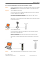
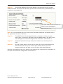
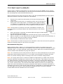
WESII User Manual 10.2 Spacing required when mounting WESII units See section 5 for mounting instructions. When mounting units in a relay configuration the following distances between units are required. Note: The operation of the units must be as depicted, failure to comply with these instructions will invalidate warranty. Manual-WESII-Rev1403 Copyright © KBC Networks 2014 Page 93 of 140 www.kbcnetworks.com WESII User Manual 10.3 Cable lengths when installing WESII units When installing the WESII units the total combined length of cables for any configuration must not exceed 100m. Note: The type of Cat5 configuration may be determined by the LAN port of the Ethernet device. If the port is a 10/100 port, you may require a crossover cable. A crossover cable is not necessary if the two PIMs connect into an Ethernet switch. Most cables used to connect the WESII system are configured using a straight-through color code. Manual-WESII-Rev1403 Copyright © KBC Networks 2014 Page 94 of 140 www.kbcnetworks.com WESII User Manual 10.4 Aligning the WESII units For each WESII radio in the system, carry out the following steps: • • • Ensure the WESII unit is powered either by the PIM for non-PoE units or a PSE (eg.Ethernet switch) for PoE units. The WESII unit’s power LED should be green, ensure that the cable into the LAN port is seated properly. Align the Client unit(s) to the Host unit so that they are pointing directly towards each other. The RSSI level of the link needs to be between 40 – 50dB if possible; to check this either: o Look on the back side of the WESII unit to determine the RSSI LED status and re-position if necessary to obtain the best RSSI signal strength, or o On the Client unit in the ‘Status’ page of the GUI click on the <Align> button to determine the RSSI level and re-position as necessary. For further information see Section 11.2.1.5 Align. 10.5 Configuring IP addresses on a site When installing multiple point-to-point or point-to-multipoint groups on one site, it is important to ensure that each piece of equipment has a unique IP address. To change the WESII unit’s IP addresses from their default (192.168.1.200 – Host, 192.168.1 201 – Client) see Section 11.2.6.1 Manual setting. Manual-WESII-Rev1403 Copyright © KBC Networks 2014 Page 95 of 140 www.kbcnetworks.com WESII User Manual 10.6 Replacing / Adding a WESII Module from/to the Existing Application 10.6.1 Replacing a WESII Host unit The WESII Host/AP connects to its Client(s) based on its MAC Address. A point-to-point Host/AP can connect to one Client MAC address only. A point-to-multipoint Host/AP can connect to multiple Clients. If a Host/AP is being replaced, the Client(s) with which it is required to communicate must also be re-configured within WESII Client’s System page to ensure that the correct MAC address is selected for the new Host/AP. In addition, if adding a new Host/AP to an existing application the Host/AP must be configured to an available frequency not being used by the existing system. 10.6.2 Replacing a WESII Client unit If a Client is being replaced, or added to a point-to-multipoint network, it’s SSID, Country Code and channel spectrum width settings must be configured to match the Host/ AP configuration with which it wants to connect. If a Client is being replaced in a point-to-point network see Section 9 to reconfigure the link. Manual-WESII-Rev1403 Copyright © KBC Networks 2014 Page 96 of 140 www.kbcnetworks.com WESII User Manual 11 Graphical User Interface The WESII Graphical User Interface can be accessed in the following ways: • • • • connecting directly to the WESII unit through the PIM for non-PoE units connecting via the PSE (eg. Ethernet switch) for PoE units via a WESII point-to-multipoint Host/AP connection to a Client PC/laptop over a WESII wireless connection 11.1 Connecting to the WESII GUI using a PC 11.1.1 For a WESII non-PoE unit: Connect the first Ethernet straight through cable from the ‘IN’ on the PIM to either a laptop or a PC LAN port. Connect the second Ethernet straight through cable from ‘OUT’ on the same PIM to the WESII Host LAN port. Apply power to the PIM with the provided 24Vdc PSU, ensure that the green LED on the PIM is illuminated. Allow 60 seconds for the unit to boot up. See Section 7 for WESII LED boot up process. Note: Due to various port types, a crossover Ethernet cable may be required between the Ethernet device and ‘IN’ port on the PIM. KBC Networks recommends a crossover cable be available during set up, trouble-shooting and maintenance of the system. Manual-WESII-Rev1403 Copyright © KBC Networks 2014 Page 97 of 140 www.kbcnetworks.com WESII User Manual 11.1.2 For a WESII PoE unit: Connect an Ethernet cable from the PSE device (eg. Ethernet switch) to the LAN port of the WESII unit. Connect the second Ethernet straight through cable to either a laptop or a PC LAN port. Apply power to the PSE device and allow 60 seconds for the unit to boot up. See Section 7 for the WESII LED boot up process. 11.1.3 Accessing the GUI via a Web Browser The computer used to access the WESII GUI must be set to a static IP address on the same subnet as the WESII unit. The WESII default configuration is on the 192.168.1.x subnet (refer to any provided documentation for the exact IP address for the individual unit) therefore the computer must also be set to a 192.168.1.x IP address if the unit is still on its factory set configurations. Once the computer’s IP address is confirmed, open a web browser such as MS Internet Explorer® or Mozilla Firefox®. Type in the Host/AP (192.168.1.200 default) or Client (192.168.1.201 default) IP address in the address bar at the top of the web browser. If the IP is correct and the link activity is established, the browser will prompt you to enter the User Name and Password. The User Name and Password are ‘admin’ / ‘admin’ (case sensitive). User Name: admin Password: admin Manual-WESII-Rev1403 Copyright © KBC Networks 2014 Page 98 of 140 www.kbcnetworks.com WESII User Manual 11.2 WESII Menu Options The WESII has the following menu options for United States & Canada and EMEA firmware: • DIAGOSTICS o o o • NETWORK o • Basic Network BASIC WIRELESS o • Status Services Topology Radio 1 ADVANCED WIRELESS o Radio 1 The WESII has the following menu options for Australian firmware: • DIAGOSTICS o o o • Status Services System NETWORK o o o Basic Network Basic Wireless Advanced Wireless Manual-WESII-Rev1403 Copyright © KBC Networks 2014 Page 99 of 140 www.kbcnetworks.com WESII User Manual 11.2.1 DIAGNOSTICS 11.2.1.1 Status The initial page displayed on the web browser GUI is the ‘Status’ screen. The individual sections and description are as follows: Manual-WESII-Rev1403 Copyright © KBC Networks 2014 Page 100 of 140 www.kbcnetworks.com WESII User Manual 11.2.1.2 Status: MAIN The ‘MAIN’ section shows the Uptime, the Host Name and System Time information. Uptime: This shows the number of hours and minutes since the last reboot or when the system was initially powered up. Host Name: This displays the chosen name of the device as set in the ‘SYSTEM’ menu. System Time: This is the internal clock of the device. This is not the actual time but is used for the scheduled reboot function found in the ‘SYSTEM’ page. 11.2.1.3 Status: VERSION The ‘VERSION’ section shows the Firmware Version information. Firmware Version: This is the firmware version loaded onto the WESII unit. 11.2.1.4 Status: LAN SETTING The ‘LAN SETTING’ section shows the LAN MAC, Mode, IP Address, Gateway IP Address and LAN cable information. These are set in the ‘Basic Network’ menu option see Section 11.2.6. The Host/AP default configuration is: Manual-WESII-Rev1403 Copyright © KBC Networks 2014 Page 101 of 140 www.kbcnetworks.com WESII User Manual The Client default configuration is: LAN MAC: this is the unit’s own MAC address for the Ethernet LAN side of the device. There are two MAC addresses per WESII unit; the radio also has its own MAC address this can be found under the Radio 1 tab. MODE: this shows whether the unit is set to either a static IP address or DHCP in the ‘Basic Network’ menu. IP ADDRESS: this is the IP address of the unit. The addresses shown above are the default IP addresses for the units. GATEWAY IP ADDRESS: this is the Gateway IP address shown under the Basic Network setting menu. If access is required to the WESII unit from outside of the network then this could be the router address. If the unit has the Topology function this needs to be a pingable IP address on the network. LAN cable: this shows whether there is LAN cable connected or not. 11.2.1.5 Status: Radio 1 Tab Details of the WESII unit accessed are recorded and appear on this status information tab. If a connected WESII device is available on the RF link, its MAC address and other link details will also appear. This page assists in providing critical details needed for wireless link set up, trouble-shooting and/or maintenance. Manual-WESII-Rev1403 Copyright © KBC Networks 2014 Page 102 of 140 www.kbcnetworks.com WESII User Manual Client Radio 1 tab: Host/AP Radio 1 tab: Manual-WESII-Rev1403 Copyright © KBC Networks 2014 Page 103 of 140 www.kbcnetworks.com WESII User Manual Wireless Mode: This shows whether the unit is either set as a Station (WESII Client) or Access Point WDS (WESII Host/AP). Note: Host/APs and Clients are pre-set in the factory and cannot be changed. MAC: Each Ethernet device has a unique MAC (Media Access Control) address. This number should be used to track and reference the WESII units. All single point Host/APs are locked to one Client MAC address only. If a replacement Client is deployed, its MAC address must be entered into the Host/AP in order to connect. LOCAL AP SSID: This displays the SSID (Service Set Identifier) chosen on the ‘BASIC WIRELESS – Radio 1’ interface page. Frequency: This displays the frequency used for the Host/AP to connect to the Client. The Client will automatically connect to the same Host/AP frequency once it is locked to it. Security: This displays the encryption method selected on the ‘BASIC WIRELESS – Radio 1’ interface page. Refresh: This button refreshes the ‘Bytes’, ‘Packets’ and ‘Errors’ information as well statistics from the connected Client(s). Align: When a Host and Client are connected the interface displays an alignment tool button on the Client unit. The WESII antennas need to be aligned to their respective mate. This tool can be used to identify the optimal mounting alignment. Connected Stations: the number of devices connected to the Host is shown in parenthesis. When a Client is connected to a single point Host/AP (or multiple Clients to a point-to-multipoint Host/AP), the MAC address(es), Signal Strength(s), TX Rate(s), TX CCQ(s), RX Rate(s) and Channel Width(s) will also be displayed. These are used to identify if the signal strength and data rates are sufficient for a wireless connection needed for a constant stream of video. In the screen shot below the important details are defined: MAC Address: the MAC address of the connected WESII unit. Manual-WESII-Rev1403 Copyright © KBC Networks 2014 Page 104 of 140 www.kbcnetworks.com WESII User Manual Signal Strength: This is the RSSI (Received Signal Strength Indication) ranging from 0100. The RSSI, is the measure of the strength of the RF connection between radios. The RSSI number in the screen shot above is ‘70’ with the numbers within the parenthesis showing the RSSI’s for the vertical (77) and horizontal (53) portions of the radio (ie. the 2x2 function of the MIMO). The vertical and horizontal RSSI figures can be used if two separate directional antennas require individual alignment. Certain variables exist by which this indicator is established. If line of sight, interference or other adverse site specific conditions exist, the RSSI will be limited to a much lower number on the 0-100 scale. The RSSI in the above screen shot was attained when the radios were in very close proximity on a bench test. When distance is increased between the radios and other variables are introduced the number will drop significantly from the high numbers shown. A reasonable RSSI for average deployments will be in the 40 to 50 range. A bare minimum RSSI that KBC Networks recommends to maintain an RF link for constant streaming video is no less than 20. If max TX and RX rates are established at lower RSSIs then the system is performing as optimally as possible in a harsh RF environment. Tx / Rx Rates: The rate of transmission and reception is auto-negotiated with the opposite radio in the RF connection. The system attempts to establish a link at the maximum rate of 162Mbps (in 40 MHz bandwidth) however, if the environment restricts a connection at the maximum rate, the radios will attempt connection at the next lower rate. It will continue to auto-negotiate the rate until a connection can be established. Tx CCQ: Transmission Client Connection Quality – this value, shown as a percentage, shows how effective the transmitted bandwidth being used is compared to the theoretical maximum bandwidth. Channel Width: The selected bandwidth from ‘BASIC WIRELESS – Radio 1’ is shown. Other options include HT5 and HT20. The larger the bandwidth the lower number of channel options available to use. Local AP Statistics: The transmitted and received data packets over the RF connection are recorded and viewable here. Any error will also be captured. The refresh button will update the transmission statistics. Local AP Errors: Any additional error and/or collision in the wireless traffic when a Host is connected to a Client or group of Clients will be captured and displayed in this section helping to identify the loss of data over the wireless link. Manual-WESII-Rev1403 Copyright © KBC Networks 2014 Page 105 of 140 www.kbcnetworks.com WESII User Manual 11.2.1.6 Status: More status In the top right hand corner of the screen there is a pull down menu ‘More Status’. This is a quick link tool to various services diagnostic tools. See Section 11.2.2 for more details. Ping Utility: Use this tool to ping from within the WESII node. ARP Table: This allows you to view the ARP Table. Bridge Table: This allows you to view the Bridge Table. Manual-WESII-Rev1403 Copyright © KBC Networks 2014 Page 106 of 140 www.kbcnetworks.com WESII User Manual 11.2.2 Services The ‘Services’ menu is where the tools to set-up trouble-shooting and maintenance are found. Manual-WESII-Rev1403 Copyright © KBC Networks 2014 Page 107 of 140 www.kbcnetworks.com WESII User Manual 11.2.2.1 Services: SPANNING TREE PROTOCOL (STP) SETUP If the WESII topology involves redundant paths where there are loops in the network, Spanning Tree Protocol (STP) must be enabled. Any node can then be manually set as the Root Bridge in order to identify which link STP will break. The lower the root priority, the greater the significance of the link as it pertains to STP. If kept to default configurations, STP will decide which link is to be broken based on a few variables (which determine the highest root priority number). If another established link goes down for any reason, STP will then enable the link that it chose previously to break. 11.2.2.2 Services: PING WATCHDOG The ping watchdog serves as an option to perform an automatic power cycle if the unit loses connection to a particular IP address. As soon as the system can no longer ping an IP on the network under the conditions for which it is set, the unit will reboot. When enabled the system will begin pinging the IP entered after the given interval and will function as configured. It must be configured to wait for a particular number of non-responses (typically five) before rebooting. It will reboot then try the ping again. In the example below (a picture of the default configurations) the unit will start to ping 192.168.1.1 after 60 seconds. Each ping can be set to the desired interval between pings adding to or subtracting from the amount of time elapsed before failure responses create the need for a reboot. Note: the ping watch dog should never be used with a device that obtains its IP via DHCP, it should only be used with devices using static IP addresses. The main purpose for a ping watchdog is a quick solution to re-connect the RF link in the event of interference, a network issue or where some other site specific adverse condition locks up a Host/AP or Client. Rebooting the device can clear ARP (Address Resolution Protocol) tables or resolve other network issues that might have forced the unit to lock up. Rebooting may temporarily solve the issue but may not address an actual network or other site specific condition. The tool gives the ability to re-establish a wireless connection and streaming video in the event the unit loses the RF link to its mate radio. Though this tool limits down time it may only mask the greater environmental problems at the site. KBC Networks recommends trouble-shooting all system and connection issues before resorting to the ping watchdog tool. Note: If the IP selected is not on the network, is not powered up or some other issue exists, the unit enabled with ping watchdog will continue to reboot until ping watchdog is Manual-WESII-Rev1403 Copyright © KBC Networks 2014 Page 108 of 140 www.kbcnetworks.com WESII User Manual disabled. Please disable or reset the watchdog to a different IP in the event the configured IP is known to be unreachable. 11.2.2.3 Services: NETWORK PING The network ping tool enables an IP address to be to be pinged from within the WESII unit which can help to confirm an Ethernet cable connection between the WESII unit and the Ethernet device it is connected to. This tool can ping any IP on the network given that the wireless unit has an established connection either wirelessly or over cable. Click the ‘Ping Utility’ button and the following screen will appear. Insert the IP address under ‘Destination IP/HOST’. The packet count & size can be changed to a desired number of ping attempts and length of packet. If ‘continuous’ is selected, the ping attempts will continue until ‘Stop’ button below is clicked. Continuous pings will determine when a device has reconnected after either being rebooted or having left the network. Manual-WESII-Rev1403 Copyright © KBC Networks 2014 Page 109 of 140 www.kbcnetworks.com WESII User Manual The sample IP above is a valid IP on the 192.168.1 subnet on the network. All five attempts replied indicating that the connection to 192.168.1.200 from the WESII unit which performed the ping is established. 11.2.2.4 Services: BRIDGE TABLE The Bridge table displays the MAC addresses of the connected devices to the node. The table will indicate whether the device is local to the node or if it is connected via the RF connection through one of the WiFi radios. Manual-WESII-Rev1403 Copyright © KBC Networks 2014 Page 110 of 140 www.kbcnetworks.com WESII User Manual 11.2.2.4 Services: AUTO-REBOOT The WESII can be set to reboot automatically. This can be performed at a scheduled time each day or after a given amount of time of operation. By Hour By selecting the ‘By Hour’ option, a number of hours can be inserted and the unit will reboot after the particular number of hours of operation. It will quickly soft reboot and will be available for reconnection. If its mate WESII is active, it will reconnect automatically. By Time Insert the time (according to the internal WESII clock) at which the system will reboot. Note: The internal clock cannot be set to match real time. Manual-WESII-Rev1403 Copyright © KBC Networks 2014 Page 111 of 140 www.kbcnetworks.com WESII User Manual 11.2.2.6 Services: SNMP SET UP The system is compatible with SNMP version 2. This menu option allows you to set up the SNMP instructions so that the WESII unit can communicate with externally supplied SNMP devices. 11.2.2.7 Services: NTP SETUP This menu option is used to set the system to Network Time Protocol which allows synchronization over a network. The node must be connected to the internet for the NTP set up to take place. Each node connected via the WESII link can also be set to the same NTP by using the identical NTP server and gateway IP. Select the time zone of the node deployment and check the ‘Known Time Server’ box. Ensure that all the nodes connected are using the same Known Time Server. Select <Apply> and <Save> to initiate the NTP set up. Manual-WESII-Rev1403 Copyright © KBC Networks 2014 Page 112 of 140 www.kbcnetworks.com WESII User Manual 11.2.2. 8 Services: TELNET SERVER Telnet is default enabled for port 23, the default standard for Telnet. If desired for security reasons, this option can be disabled. Telnet allows unit configuration settings and readings through command line without the use of embedded webpages. 11.2.2.9 Services: SYSTEM LOG When enabled the system will begin to log the connection status to the configured IP using Telnet via the default log port 514. Results are viewed in Telnet. Manual-WESII-Rev1403 Copyright © KBC Networks 2014 Page 113 of 140 www.kbcnetworks.com WESII User Manual 11.2.3 System The ‘System’ page allows certain configuration and upgrade changes to be performed to the WESII system. KBC Networks recommends using the configuration backup to save the settings of each unit once any custom configurations are complete. 11.2.3.1 System: FIRMWARE UPGRADE To upgrade the WESII firmware, follow the procedures below: 1. Contact KBC Networks to get a firmware upgrade emailed to you. 2. Connect an Ethernet cable from the PIM attached to the WESII RF module to the PC. 3. Access the WESII unit web browser interface and click on ‘SYSTEM’ 4. Click on <Choose File>. 5. Search for the file in the location where it was saved (under step 1 above) 6. Select the file and open it. The file name should now be seen next to the Chose File button. 7. Select <Upload> 8. Select <Yes> to continue. 9. When asked to Reboot select <Yes>. 10. When the Reboot is complete scroll down to the bottom of the page and select <Reset to defaults…> and then select <Yes> Manual-WESII-Rev1403 Copyright © KBC Networks 2014 Page 114 of 140 www.kbcnetworks.com WESII User Manual 11.2.3.2 System: HOST NAME In this menu option the unit can be given a customized name, this is then displayed in the ‘STATUS’ page. Example: If a WESII Client is at camera # 2 the host name could be ‘Camera 2’ or the position of the camera such as ‘Lot 1’. The Host name is for identification purposes only, the Host/AP does not search for a Client by its name. The default for Host/AP is simply ‘AP’ and the Client is ‘CLIENT’. Default HOST NAME on WESII Host Default HOST NAME on WESII Client 11.2.3.3 System: ADMINISTRATIVE ACCOUNT This menu option is used to change the default administrator username and password. The default settings for both of these are ‘admin’. 1. 2. 3. 4. 5. 6. Insert the new administrator username. Insert the existing password. Choose a new password and enter it in the ‘New Password’ field Confirm the new password in the ‘Verify New Password’ field. Click ‘Apply’. Click ‘Save’ next to ‘Save configuration changes’. After changing the administrator username and password names, the system will prompt another request to insert the new password and administrator username. Enter the new administrator name and password created in order to re-access the interface and continue with any other configuration changes. Restoring to defaults will return the username and password to ‘admin’ / ‘admin’ see Section 11.2.3.3 Reset to defaults for default settings. Manual-WESII-Rev1403 Copyright © KBC Networks 2014 Page 115 of 140 www.kbcnetworks.com WESII User Manual The Administrator Username can also be changed. It does not need to be ‘admin’ to change the password. The default password is ‘admin’ Change the password here and verify below System: DEVICE MAINTENANCE Reboot: this performs a re-boot to the unit, this can take up to 1 minute to perform. Reset to defaults: In this menu option the unit can be soft rebooted or reset to defaults. The default configurations are as follows: Host/AP LAN Configuration: Client LAN Configuration: Interface Access Username: Interface Access password: Hostname: 192.168.1.200 255.255.255.0 No Gateway IP 192.168.1.201 255.255.255.0 No Gateway IP admin admin AP (for the Host/AP) CLIENT (for the Client) 00:00:00:00:00:00 KBC-WESII USA (North America) Remote Client-Lock to MAC: Local AP-ESSID: Country Code: Select Country (all other countries) Wireless Profile: NA (IEEE802.11n & IEEE802.11a) NG (IEEE802.11n, IEEE802.11 g) NY (IEEE802.11n & IEEE802.11y) Channel Spectrum Width: 20/40M Channel-Frequency: set to auto-select Transmit Power: 23 dBm (North America) 19 dBm (all other countries) Local AP WPA Cipher: AES Local AP Preshared Key: 11111111 Long Range Parameters: Enabled RSSI LEDs: LED1=10; LED2=20; LED3=30; LED4=40 Manual-WESII-Rev1403 Copyright © KBC Networks 2014 Page 116 of 140 www.kbcnetworks.com WESII User Manual Hard reset to defaults A hard reset to default configurations can also be carried out on the WESII units. The reset button can be found on the bottom side of the units between the mounting block and the RJ45 Ethernet port. While performing the reset process the LED on the left (RSSI4/STATUS) will be used to determine when to hold and release the reset button. 1. 2. remove the screw from the bottom of the case which plugs the reset hole. Using a small screw driver or something which can fit through the hole, push in the reset button. The button will be approximately 1½”/38mm or so within the case. It is possible that you will need to move the screwdriver up or down slightly to find the button. Note: If the button is pushed in but then immediately released, the unit will need to be powered down and rebooted and you will need to try again. 3. 4. 5. 6. When the button is pressed, the status LED will begin to flash rapidly for approximately 5 seconds. After a short period of rapid flash, the LED will turn off for a short pause After a second or so the LED will turn on again and flash slowly and consistently so that you can count the number of times it flashes. Count exactly 3 flashes and then release Note: If the button is held too long and not released on time the unit must be powered down and rebooted and you will need to try again. Recommended Ping Test: Before starting Step 1 above, it is recommended to perform a constant ping to the default IP of the unit to be reset. For instance, if the unit is a Host the command is: ping 192.168.1.200 -t (or ping 192.168.1.200/t also works). When the unit has successfully reset to default and rebooted the ping will respond. Note: It is common for the reset process to take two or three attempts due to the strict parameters and needed learning curve. It is highly recommended to exhaust all other forms of trouble-shooting before resorting to the reset to default configurations. Note: If a single point Host is restored to default configurations, its MAC Lock function must be manually reconfigured in order to link up to its Client. This feature is found on the "Basic Wireless" section of the Host interface. The Client wireless MAC address must be entered in the typical MAC format using colons in between each pair of characters (ex: 00:01:1a:2b:3c:d5). The Client wireless MAC address is found on its status page within the radio information but may be presented with dashes in between each pair of characters (ex 00-01-1a-2b-3c-d5) which will be an invalid MAC if copied and pasted into the Host MAC lock function. Other potential changes will also be reset to defaults, contact KBC technical assistance for more details. Manual-WESII-Rev1403 Copyright © KBC Networks 2014 Page 117 of 140 www.kbcnetworks.com WESII User Manual 11.2.4 Topology The system mapping capability of the topology page enables end users to view system configuration and health all on one page. WESII topology shows the links between different Station/Clients and Host/APs. System mapping supports dynamic changes in the network so as the network changes it learns the new topology and updates this on the topology webpage. Along with system mapping, the topology view also displays all node information; this can be viewed by holding your mouse over a particular node and radio. Node hover over will display following node information: • • • • • • • Node IP address Bridge MAC address Root bridge information Gateway information Radio up/down status Radio Host/Client role Connected peer information If any parameter eg. IP address , node name , SSID etc changes then topology reports updates accordingly. Note: Only KBC Network nodes are shown on the topology page. If any node goes down within the network then it is shown in red after 100 seconds (default). If it then remains down for more than 200 seconds (default) the node entry will be removed from topology view. When the node is reconnected to the network it will be added back to the topology. Link connection lines are shown in different colors, these represent different ranges of Manual-WESII-Rev1403 Copyright © KBC Networks 2014 Page 118 of 140 www.kbcnetworks.com WESII User Manual RSSI and makes it easy to identify weak RF links. Link Color RSSI Range Dark green 40dBm and above Light green 40dBm to 30dBm Yellow 30dBm to 20dBm Orange 20dBm to 10dBm Red 10dBm and lower Hashed Indicated STP blocked port The WESII system mapping tool works with STP enabled as well as STP disabled. The Root bridge is shown by a green dot and if the Root bridge is lost then this is shown as a red dot. All wired links are shown as black lines. Maps can be imported as a background in either JPEG or GIF format. Nodes can then be moved around on the uploaded map to show them in their physical locations. If you double click on a node then the embedded UI can be accessed. The Refresh button can be used to refresh the topology page manually however it is automatically refreshed every 60 seconds. The following browsers are supported: Firefox : 13.0.1 11.0, 10.0.2, 9.0.1 Internet Explorer: 9.0, 8.0 Safari: 5.1.5, 5.1.7 Manual-WESII-Rev1403 Copyright © KBC Networks 2014 Page 119 of 140 www.kbcnetworks.com WESII User Manual 11.2.4.1 System Topology Setup Set this to a ping-able network device Step 1: All nodes within the network need to have a gateway address set on the NETWORK - Basic Network page. This gateway must be a ping-able network device that is connected to any one of the system node’s Ethernet port. It does not have to be an actual gateway just a ping-able device – for setting up this can be the PC you are connected to, you will also need to turn off the firewall on the PC too. The system mapping uses ping to the gateway as a mechanism for a low bandwidth means to confirm system connectivity. If the system map were to be viewed from outside the network, then this will be an actual gateway. Manual-WESII-Rev1403 Copyright © KBC Networks 2014 Page 120 of 140 www.kbcnetworks.com WESII User Manual Step 2: Once the WESII system can been configured and properly connected, a generic system map will be drawn like the one below: Note: a router symbol is used to represent the gateway. At this point, all nodes have the same gateway IP address which is set to the gateway shown connected to the Client. Step 3: A background image can be uploaded by selecting the <Browse> button and uploading the desired background image. Note: the image size is limited to 120KB and must be in a JPEG or GIF format. The topology page will auto size to fit the uploaded image Manual-WESII-Rev1403 Copyright © KBC Networks 2014 Page 121 of 140 www.kbcnetworks.com WESII User Manual Step 4: Once an image has been selected, select the <Upload> button. It will take approximately 20 seconds to upload and render the background image. Step 5: Move the WESII nodes around on the page to represent their physical locations as shown below: Step 6: Once the image has been loaded and the nodes moved, select <Save> to store the page configurations in nonvolatile memory. Manual-WESII-Rev1403 Copyright © KBC Networks 2014 Page 122 of 140 www.kbcnetworks.com WESII User Manual Note: The mouse hover over feature will display details for the radio as shown below: Manual-WESII-Rev1403 Copyright © KBC Networks 2014 Page 123 of 140 www.kbcnetworks.com WESII User Manual 11.2.5 NETWORK: Basic Network The ‘Basic Network’ menu option allows the LAN IP, subnet mask and Gateway IP to be set as either static IPs on the network or configured automatically by a DHCP server. 11.2.5.1 Basic Network: LOCAL AREA NETWORK Manual-WESII-Rev1403 Copyright © KBC Networks 2014 Page 124 of 140 www.kbcnetworks.com WESII User Manual LAN Mode: This can be set to either DHCP (Dynamic Host Configuration Protocol) or Static to allow the LAN IP, subnet mask and Gateway IP to be set as either static IPs on the network or configured automatically. If Static is selected enter the LAN IP, Netmask and Gateway IP using an available IP on the network. KBC Networks recommends obtaining valid unused IPs from the network administrator if the units will reside on the network. The WESII units can connect independently from the network structure and are not required to be configured as static IPs within the network subnet. If DHCP is selected the LAN configuration will be set dynamically according to the network availability. When DHCP is selected, the IP Address, Netmask and Gateway IP configuration area will be grayed out to prohibit custom LAN settings being entered as they will be obtained through the network. Once DHCP is saved an IP searching tool will be required to determine the WESII unit IP address. A locator tool which shows the Hostname can be used to distinguish the IP from other IP addresses on the network. 11.2.5.2 Basic Network: BANDWIDTH CONTROL The WESII system can control throughput into the LAN port to the radio as well as out of the radio to the LAN port, based on the desired throughput configurations. The default setting is 1Mbps for each unit with this enabled. Manual-WESII-Rev1403 Copyright © KBC Networks 2014 Page 125 of 140 www.kbcnetworks.com WESII User Manual 11.2.6 BASIC WIRELESS: Radio 1 Channel frequency selection and bandwidth options are set within the Basic Wireless: Radio 1 menu option. The Host/AP will connect to a Client provided that the SSID, MAC Lock (if applicable) and Country Code settings are the same. Manual-WESII-Rev1403 Copyright © KBC Networks 2014 Page 126 of 140 www.kbcnetworks.com WESII User Manual 11.2.6.1 Radio1: BASIC WIRELESS SETTINGS These menu option show the default settings for the Host and Client units. Host/AP Client In the AP mode the unit will connect with remote Client units which are configured with the same SSID, Country Code and Channel spectrum Width. Manual-WESII-Rev1403 Copyright © KBC Networks 2014 Page 127 of 140 www.kbcnetworks.com WESII User Manual Wireless Mode: The Wireless Mode shows whether the unit is either an Access Point/Host or a Client/Station unit. Local AP-ESSID: This is the area in which the SSID is configured if a custom SSID is desired. Remote Client-Lock to MAC: Point-to-point Host/APs will only connect to one Client. If the Host/AP is meant to connect with a WESII Client, enter the Client’s MAC Address in this location on the Host unit. The Client will also need to know the Host/AP MAC address. This can be determined by selecting the <Site Survey> button on the Client unit and then selecting the MAC address of the Host/AP unit from the list, this will automatically put the MAC address into the Remote Client –Lock to MAC field Multipoint Host/APs do not require the MAC lock. Ptmp Host/APs will connect to any WESII Client using the same SSID and Country Code. To specify a particular group of Clients to associate with a particular Ptmp Host/AP, set the group to the same SSID and record all configuration changes. Hide SSID: If the SSID should not be broadcast for other Clients to see it can be hidden by selecting this box. The AP’s MAC address will still appear in AP lists but will not show the SSID. Country Code: Select the country in which the system will be deployed. The radio will then transmit under the legal operation for that particular regulatory domain. Any restricted channels will no longer be available for static selection and power output will also be tailored to the regulations of the local country. If using an external antenna, use only the power output regulated per dB gain of the antenna. Note: A Country Code selection is not require for North America Wireless Profile: Depending on the unit you have purchase this will either be: ‘NA’ to show that the system is working to IEEE802.11a and IEEE802.11n specifications (5Ghz operation and using MIMO technology). ‘NG’ to show that the system is working to IEEE802.11g and IEEE802.11n specifications (2.4GHz operation and using MIMO technology). ‘NY’ to show that the system is working to IEEE802.11y and IEEE802.11n specifications (4.9GHz operation and using MIMO technology). Manual-WESII-Rev1403 Copyright © KBC Networks 2014 Page 128 of 140 www.kbcnetworks.com WESII User Manual Channel Spectrum Width: The number of channels availability is based on the channel spectrum width chosen. If a larger spectrum width is chosen then additional throughput capability becomes available. By choosing a smaller channel spectrum width, more channels are available but with less throughput and there is a greater chance of frequency bleed-over. Below is a chart to show the potential throughput based on spectrum width: MCS Index Spatial Streams Modulation Type Coding Rate 8 9 10 11 12 13 14 15 2 2 2 2 2 2 2 2 BPSK QPSK QPSK 16-QAM 16-QAM 64-QAM 64-QAM 64-QAM 1/2 1/2 3/4 1/2 3/4 2/3 3/4 5/6 Data Rate (Mbps) 20 MHz Channel 800 ns 400 ns GI GI 13.00 14.40 26.00 28.90 39.00 43.30 52.00 57.80 78.00 86.70 104.00 115.60 117.00 130.00 130.00 144.40 40 MHz Channel 800 ns 400 ns GI GI 27.00 30.00 54.00 60.00 81.00 90.00 108.00 120.00 162.00 180.00 216.00 240.00 243.00 270.00 270.00 300.00 Where: MCS: Modulation and Coding Scheme. Spatial Streams: all WESII radios are 2x2 Modulation Types: BPSK= Binary Phase-Shift Keying QPSK= Quadrature Phase-Shift Keying QAM= Quadrature Amplitude Modulation Coding Rate: Useful proportion of the data-stream GI: Guard Interval Channel-Frequency: The frequency to be used can be either be selected automatically by the Host/AP based on the Country Code selection and Spectrum Width or manually. Manual-WESII-Rev1403 Copyright © KBC Networks 2014 Page 129 of 140 www.kbcnetworks.com WESII User Manual Automatic: The frequency used can be selected automatically on the Host/AP unit. To do this, select the Basic Wireless: Radio 1 option and ensure the ‘Auto’ box next to the Channel-Frequency is ticked. The frequencies available to be automatically selected will be based on both the Country Code and Spectrum width chosen. Ensure that the ‘Auto’ box is checked Select: BASIC WIRELESS: Radio 1 on the Host/AP unit Manual setting: The frequency can also be selected manually, this is necessary if there are more than one WESII links on a site. It is recommended that an Interference Analyzer survey is conducted to determine which frequencies are the least congested to use. See the Interference Analyzer section below for details. Setting the Host/AP frequency: On the Host/AP unit in the Basic Wireless: Radio 1 option use the drop down menu to choose a unique frequency for the link you are setting up. Frequencies available will depend upon the Country Code Spectrum Width selected. Once a frequency has been selected select <Apply Settings>. US firmware version Note: on the EMEA firmware versions you can choose whether to include the 5600 – 5650MHz band. If these frequencies are included the link connection time can increase to 10 mins due to Dynamic Frequency Selection (DFS) regulations see page 7. EMEA firmware version Manual-WESII-Rev1403 Copyright © KBC Networks 2014 Page 130 of 140 www.kbcnetworks.com WESII User Manual Setting the Client frequency: The Client obtains its frequency from its connected Host/AP. To ensure that a particular Client connects to a certain Host/AP, the SSID, Country Code and Channel Width settings need to be the same as the Host/AP unit to which the unit wishes to connect to. On the Client unit, in the Basic Wireless: Radio 1 menu option, ensure that the Remote AP-Lock to Client is ticked. Click on <Site Survey>, select the MAC address of the Host/AP unit you wish to connect to. This will now be shown in the box next to the <Enabled> box. The units will now connected on the designated frequency – this may take a few minutes. Interference Analyzer: The interference Analyzer facility is located on the Host/AP unit and can be used to determine whether there are other pieces of equipment in the vicinity using the same frequencies as the WESII units use. By carrying out an interference analyzer survey, congested channels can be avoided when selecting channels manually. Note: Surveys to detect interference should only be conducted when directly connected to the Host/AP, if connected to the Host/AP via the Client over the wireless link, the link will be disconnected. To carry out a frequency site survey select <Interference Analyzer>. The Interference Analyzer is only found on the Host/AP unit and only available if a channel width of either 20M or 20/40MHz is selected. Manual-WESII-Rev1403 Copyright © KBC Networks 2014 Page 131 of 140 www.kbcnetworks.com WESII User Manual In the example above, the 5GHz frequency band is shown with green color bars to indicate the other APs that are in the environment. As the color bar becomes larger it changes from green to red, to indicate the stronger RSSI of other equipment and greater chance for interference if operating on that channel. Transmit Power: The Transmit Power option allows the output power to be adjusted. US firmware version If using an external antenna in North America, the power output must be lowered for dB gain antennas of greater than 22dBi. The power output max for global deployments is 19dBm. Please check legal requirements according to the local regulatory domain for use with high gain parabolic, patch, sector or other antenna types. Manual-WESII-Rev1403 Copyright © KBC Networks 2014 Page 132 of 140 www.kbcnetworks.com WESII User Manual EMEA firmware version Note: It is the responsibility of the user to operate the system under the local regulatory domain requirements. KBC Networks recommends researching the regulations prior to deploying a license free wireless system. Local AP – Wireless Security The Local AP section is used to configure the Host/AP as an Access Point in order to connect using a laptop/PC via WiFi connection. If the Host/AP is a single point Host/AP, it cannot connect to a WESII Client and a computer client at the same time due to the remote Client MAC lock. For a computer to obtain access via WiFi AP, the laptop/PC must be configured to the security (WPA2) and cipher type (AES is default configuration) selected. The SSID will appear in the computer’s available APs list unless “Hide SSID” is selected. Once the WESII Host/AP is selected the WPA Pre-shared Key must be entered as the AP password. The default configuration is 11111111 but it can be set to any desired pre-shared key. Manual-WESII-Rev1403 Copyright © KBC Networks 2014 Page 133 of 140 www.kbcnetworks.com WESII User Manual 11.2.7 Advanced Wireless Configuration: Radio 1 This section can be used to alter the long range parameters of the link, this is necessary for wireless link lengths exceeding 1.6km/1 mile and also to alter the value of the signal strengths of the RSSI LEDs located on the back of the WESII units. Long Range Parameters It is recommended that for all links over 1.6km (1mile) the long range parameters must be set. In the example below, the WESII is configured for a 1600m (1 mile) connection. Both the Host/AP and Client units must be configured for the distance parameters: Manual-WESII-Rev1403 Copyright © KBC Networks 2014 Page 134 of 140 www.kbcnetworks.com WESII User Manual Other Settings Noise Immunity The default setting for Noise Immunity is to be Enabled. Signal Strength Indicator (RSSI) The following are the default RSSI LED configurations. These parameters can be changed to any desired RSSI (0 through 100). Manual-WESII-Rev1403 Copyright © KBC Networks 2014 Page 135 of 140 www.kbcnetworks.com WESII User Manual 12 Troubleshooting 12.1 Visual Inspection If the WESII antennas can be accessed, the status LEDs can be investigated to determine if there is an obvious answer to the problem. 12.1.1 LED Status If the Link Activity LED is not illuminated then the WESII RF Module does not sense an established cable link from the Ethernet device through the PIM to the WESII unit. Check all cables and connectors as well as connections into and out of the PIM. For instance, if the ‘IN’ side of the PIM is connected to the WESII, the device will receive its power but the Link Activity LED will not be on. If all four of the RSSI LEDs are not lit then the link may be unsatisfactory. Another frequency or more alignment may be necessary. If connecting long range, visit the ‘Long Range Parameters’ in the GUI for the Host/AP and Client and insert the approximate distance in meters. See Section 11.2.7 Long Range Parameters. WESII units operating with EMEA firmware may take longer times to connect on certain frequencies see Page7 for details. 12.2 Test Cable Connections 12.2.1 Determine Link Activity Obtain an IP locating device and search for the Host/AP and/or Client IP address. First attempt to locate and/or ping the locally connected WESII device then attempt to ping the remote WESII antenna. If the pings reply then the link is established to the local unit. If the ping does not reply or the GUI is not accessible for the remote WESII antenna then access the GUI for the local device and try the ping from within the WESII. 12.2.2 Test Wireless Device over Cable (without the WESII) A bench test is always recommended in order to test the wirelessly connected devices over a cable connected link. This verifies that the devices in line with the WESII are operating. In addition, a test with the WESII in line while transmitting in a sterile environment will help to ensure that the wireless system is working properly. 12.3 GUI Tools See section 3 of this manual for the diagnostic tools available to use to determine the problem and probable solution. Contact KBC Networks for technical assistance. Manual-WESII-Rev1403 Copyright © KBC Networks 2014 Page 136 of 140 www.kbcnetworks.com WESII User Manual 12.4 Hard reset to defaults A hard reset to default configurations can be carried out on the WESII units to restore default settings. The reset button can be found on the bottom side of the units between the mounting block and the RJ45 Ethernet port. While performing the reset process the LED on the left (RSSI4/STATUS) will be used to determine when to hold and release the reset button. 1. 2. Remove the screw from the bottom of the case which plugs the reset hole. Using a small screw driver or something which can fit through the hole, push in the reset button. The button will be approximately 1½”/38mm or so within the case. It is possible that you will need to move the screwdriver up or down slightly to find the button. Note: If the button is pushed in but then immediately released, the unit will need to be powered down and rebooted and you will need to try again. 3. 4. 5. 6. When the button is pressed, the status LED will begin to flash rapidly for approximately 5 seconds. After a short period of rapid flash, the LED will turn off for a short pause After a second or so the LED will turn on again and flash slowly and consistently so that you can count the number of times it flashes. Count exactly 3 flashes and then release Note: If the button is held too long and not released on time the unit must be powered down and rebooted and you will need to try again. Recommended Ping Test: Before starting Step 1 above, it is recommended to perform a constant ping to the default IP of the unit to be reset. For instance, if the unit is a Host the command is: ping 192.168.1.200 -t (or ping 192.168.1.200/t also works). When the unit has successfully reset to default and rebooted the ping will respond. Note: It is common for the reset process to take two or three attempts due to the strict parameters and needed learning curve. It is highly recommended to exhaust all other forms of trouble-shooting before resorting to the reset to default configurations. Note: If a single point Host is restored to default configurations, its MAC Lock function must be manually reconfigured in order to link up to its Client. This feature is found on the "Basic Wireless" section of the Host interface. The Client wireless MAC address must be entered in the typical MAC format using colons in between each pair of characters (ex: 00:01:1a:2b:3c:d5). The Client wireless MAC address is found on its status page within the radio information but may be presented with dashes in between each pair of characters (ex 00-01-1a-2b-3c-d5) which will be an invalid MAC if copied and pasted into the Host MAC lock function. Other potential changes will also be reset to defaults, contact KBC technical assistance for more details. Manual-WESII-Rev1403 Copyright © KBC Networks 2014 Page 137 of 140 www.kbcnetworks.com WESII User Manual 12.5 Contact KBC Technical Assistance Below is the contact information for KBC: Technical Support Availability This manual is comprehensive to the extent that it will answer many of your technical questions. Our toll free technical assistance is available should you require additional assistance. KBC offers technical support over the phone or by way of e-mail to all KBC integrators, dealers and end users of the WES products. Our technical support hotline is available during regular US west coast business hours, Monday through Friday on all non-major holiday business days. KBC will follow up on all electronic inquiries before the end of the following business day. NORTH AMERICA (TOLL-FREE) 888-366-4276: Monday – Friday 10am-8pm Eastern (7am-5pm Pacific) [email protected]: 24hr availability, response time varies HAWAII & ALASKA / GUAM, PR & OTHER US TERRITORIES 949-297-4930: Monday – Friday 7am-5pm Pacific Time [email protected]: 24hr availability, response time varies Note: the toll free 888# does not work from Alaska CENTRAL / SOUTH AMERICA [email protected]: 24hr availability, response time varies ASIA [email protected]: 24hr availability, response time varies SOUTH PACIFIC / PACIFIC ISLANDS [email protected]: 24hr availability, response time varies EUROPE +44(0)1622 618787: Monday – Friday 9am-5pm UK time [email protected]: 24hr availability, response time varies AFRICA & MIDDLE EAST [email protected]: 24hr availability, response time varies Technical Support is offered in English; however, KBC Networks has worldwide representatives who can provide technical support in many local languages. Note: technical assistance is available after having read through this manual. Comprehension of terms and topics will assist in trouble-shoot procedures. Manual-WESII-Rev1403 Copyright © KBC Networks 2014 Page 138 of 140 www.kbcnetworks.com WESII User Manual 13 Warranty 13.1 Warranty Information 1. KBC extends the following LIMITED WARRANTY to the original owner/purchaser of this product as follows: - Five years from the date of initial sale for Ethernet switches. Two years from the date of initial sale for all wireless and other network products. Five years from the date of initial sale for all fiber products. 2. If, within the specified warranty period, this product, or any part or portion thereof, shall prove upon examination by KBC, to be defective in material or workmanship, KBC will repair or replace such part or portion at KBC’s option. The warranty period on the repaired or replaced part or portion of this product shall be limited to the unexpired term of the original warranty. The buyer shall be responsible for all shipping and transportation of the product to KBC for any performance under this warranty. 3. Conditions and Exceptions: a. Any accident to this product, any misuse or abuse, alternation, use in modified form, or any attempt to repair this product shall void this warranty. These conditions to the warranty include, but are not limited to, incorrect power connections, physical damage due to mechanical shock, exposure to moisture, and circuit modification. b. SHOULD THIS PRODUCT PROVE DEFECTIVE FOLLOWING PURCHASE, THE BUYER, NOT THE MANUFACTURER, DISTRIBUTOR, OR RETAILER, ASSUMES THE ENTIRE COST OF ALL SERVICING OR REPAIR, EXCEPT AS OTHERWISE PROVIDED BY THE TERMS OF THIS WARRANTY. c. FOR BREACH OF ANY WRITTEN OR IMPLIED WARRANTY ON THIS PRODUCT, THE BUYER IS LIMITED TO THE FOLLOWING DAMAGES. (1) THE COST OF LABOR TO REPAIR OR REPLACE DEFECTIVE PARTS OR PORTIONS OF THIS PRODUCT, AND (2) THE COST OF THE REPAIRED OR REPLACE PARTS OR PORTIONS OF THIS PRODUCT. d. NO OTHER EXPRESSED OR IMPLIED WARRANTIES HAVE BEEN MADE OR WILL BE MADE ON BEHALF OF KBC WITH RESPECT TO THE SALE, REPAIR, INSTALLATION, OPERATION, OR REPLACEMENT OF THIS PRODUCT. KBC DISCLAIMS ANY IMPLIED WARRANTY OF MERCHANTABILITY OF THIS PRODUCT OR ITS FITNESS FOR ANY PURPOSE, AND THE BUYER AGREES THAT THIS PRODUCT IS SOLD “AS IS” AND THAT THE ENTIRE RISK OF QUALITY AND PERFORMANCE OF THIS PRODUCT IS WITH THE BUYER, EXCEPT AS OTHERWISE PROVIDED BY THE TERMS OF THIS WARRANTY. e. Some states/jurisdictions do not allow exclusions or limitations of incidental or consequential damages, or limitations on how long an implied warranty lasts, so the above exclusions or limitations may not apply to you. f. If you do not wish to be bound by any of the provisions in this warranty, please return the product(s) immediately. 4. Contact your dealer regarding return authorizations for out of warranty repairs and any further product information. This warranty does not apply in Australia. Manual-WESII-Rev1403 Copyright © KBC Networks 2014 Page 139 of 140 www.kbcnetworks.com WESII User Manual KBC Networks North America. 25691 Atlantic Ocean Drive Suite 3B Lake Forest, CA 92630 U.S.A Americas Phone: 1-949-297-4930 Fax: 1-949-297-4933 KBC Networks Ltd. EMEA KBC Networks Ltd. Barham Court Teston, Maidstone Kent, ME18 5BZ United Kingdom Phone: +44(0)1622 618787 Fax: +44(0)20 7100 8147 Email:Manual-WESII-Rev1403 [email protected] Web: Copyright © KBC Networks 2014 www.kbcnetworks.com Page 140 of 140 www.kbcnetworks.com