1
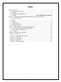
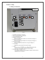
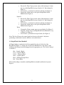
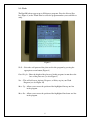
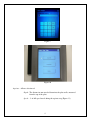
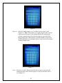
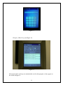
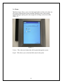
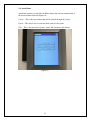
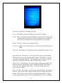
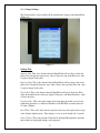
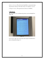
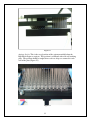
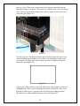
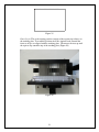
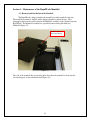
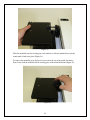
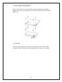
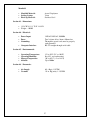
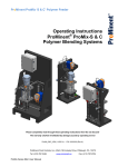
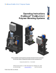
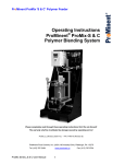
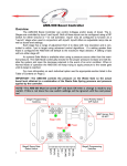
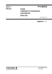
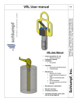
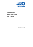
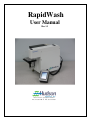
RapidWash
User Manual
Rev 1.2
10 Stern Avenue, Springfield, NJ 07081
Tel: 973-376-7400 ♦ Fax: 973-376-8265
Index
Section 1 - Setup ................................................................................................................. 3
1.1- Tubing and Connections .......................................................................................... 3
1.2 - Bottles .................................................................................................................... 4
1.2- RapidWash Select Manifold .................................................................................... 5
1.4 - Trough ...................................................................Error! Bookmark not defined.
Section 2 - Operation of RapidWash through the Touch Screen Controller ...................... 7
2.1 - Key Pad Functions .................................................................................................. 7
2.2 - Wash ....................................................................................................................... 8
2.3 - Prime..................................................................................................................... 12
2.4 - Auto Prime............................................................................................................ 13
2.5 - Maintenance Mode ............................................................................................... 14
2.6 – Change Settings ................................................................................................... 17
Section 3 - Maintenance of the RapidWash Manifold ...................................................... 23
3.1 - Removal and Installation of the Manifold ............................................................ 23
3.2 - Disassembly of the Manifold ................................................................................ 25
3.3 - Cleaning ................................................................................................................ 25
Section 4 - Hardware Specifications ................................................................................. 26
Section 4.1 - General..................................................................................................... 26
Section 4.2 - Mechanical Description: .......................................................................... 26
Section 4.3 - Materials: ................................................................................................. 26
Section 4.3 - Dimensions: ............................................................................................. 27
Section 4.4 - Electrical: ................................................................................................. 27
Section 4.5 - Environmental: ........................................................................................ 27
2
Section 1 - Setup
1.1- Tubing and Connections
Rear Panel
1
2
4
8
9
5
6
3
7
Figure 1
12345678-
9-
Touch Screen Display Connection
RS-232 Communication Connection
AC Inlet For Power Cable
Liquid 1 Level Sensor
Position around Liquid 1 bottle close to bottom (See Figure 2)
Liquid 2 Level Sensor
Position around Liquid 2 bottle close to bottom (See Figure 2)
Waste Level Sensor
Position around Waste bottle close to top (See Figure 3)
Vac Control
Output for remote control for external vacuum
Air In
From air source 40-70 PSI to rear of Rapid Wash, this for the
internal pressure regulator and optional plate gripper
Pressure source for Liquid 1 and 2
1/4" OD tube connected between Liquid 1/ liquid 2 bottles and rear
of RapidWash (See Picture 2)
3
Liquid 1 and 2
Dispense Bottle
Tubing for
Liquid 1 or 2
Pressure source
Tubing to Liquid 1
or Liquid 2 Port on
Select Manifold
Liquid Level
Sensor location
Figure 2
Waste Bottle
Waste Level
Sensor location
Tubing For Waste Port
on Select Manifold
Tubing to
Vacuum Source
Figure 3
1.2 - Bottles
Liquid 1
4
•
•
•
Pressure In- From 12psi pressure source (#9 from figure 1) from
the rear of the RapidWash to top of bottle (1/4” blue tubing-See
Figure 2)
Level Sensor - positioned near bottom of bottle (See Figure 2)
Liquid Out - From bottle to side port of RapidWash Select
Manifold (See Figure 4)
Liquid 2
• Pressure In- From 12psi pressure source (#9 from figure 1) from
the rear of the RapidWash to top of bottle (1/4” blue tubing-See
Figure 2)
• Level Sensor - positioned near bottom of bottle (See Figure 2)
• Liquid Out - From bottle to side port of RapidWash Select
Manifold (See Figure 4)
Waste
• Vacuum In - From vacuum source to top of bottle (See Figure 3)
• Liquid In - From side port of RapidWash Select Manifold to top
of bottle (See Figure 4)
• Level Sensor - positioned near top of bottle (See Figure 3)
Note: The Level Sensors for source liquids and waste are identical. Only their
positioning on the bottles must be different, as described above.
1.2- RapidWash Select Manifold
All Liquid tubing is attached to the Select manifold on the side left side of the
RapidWash (Figure 4). All the ports on the Select Manifold are color coded, so the
matching color fitting should be plugged into the appropriate port. The Color Coding is
as followed.
Blue – Liquid 1 Bottle
Green – Liquid 2 Bottle
Yellow – Dispense Head
White – Aspirate Head
Black – Priming Trough Waste
Red – Waste Bottle
When all the tubing is installed on the RapidWash it should look like the Layout in
Figure 5
5
RapidWash Select Manifold
Figure 4
Figure 5
6
Section 2 - Operation of RapidWash through the Touch Screen
Controller
2.1 - Key Pad Functions
Wash – Up to 20 Wash programs can be created and stored
Prime - Pumps either liquid 1 or 2 through the dispense manifold
Auto-Prime - Allows the dispense path to be primed on a time interval
Maintenance Mode - Tools for cleaning dispense and aspirate paths
Change Settings – Define parameters for operation such as plate locations
Figure 7
7
2.2 - Wash
The RapidWash can support up to 20 dispense programs. Press the Next or Prev
key (Figure 8) on the Touch Panel to select the program number you would like to
setup.
Figure 8
Wells – Select the well pattern of the plate used in this program by pressing the
appropriate screen button (Figure 8)
Plate Height – Enter the height of the plate used in this program, in mm above the
base of the plate nest (see also Figure 9)
New – This will add a new Aspirate, Dispense, or Delay step in your Wash
Program (see also Figure 10)
Move Up – Allows you to move the position of the highlighted line up one line
in the program.
Move Dn – Allows you to move the position of the highlighted line down one line
in the program.
8
Figure 9
Figure 10
Aspirate – Allows selection of:
Depth - The distance in mm traveled down into the plate wells, measured
from the top of the plate.
Speed - % of full speed travel during the aspirate step (Figure 11).
9
Figure 11
Dispense – Select the liquid number (1 or 2) and the desired volume, in uL
(Figure 12). Note: If the liquid (1 or 2) being dispensed has not been
primed into the dispense head, the RapidWash will automatically
perform a priming step prior to the first dispense step in the Wash
Program being run. Subsequently, if only that liquid is dispensed in
that Wash Program, the remaining dispense steps will execute without
another priming action.
Figure 12
Delay – Entered as seconds. During a delay the plate is moved away from the
manifold and the washer will not aspirate or dispense until the delay is
over (Figure 13).
10
Figure 13
Example of Wash Program (Figure 14)
Figure 14
All program values and steps are automatically saved to that program, as they appear on
the screen in Figure 14.
11
2.3 - Prime
The Prime feature allows you to select the liquid number and the total volume (in
uL) dispensed through the dispense manifold. Priming occurs at the priming
trough. During the prime process the trough will self empty to the waste bottle
(Figure 15).
Figure 15
Volume – This is the total volume that will be primed through the system.
Liquid – This allows you to select the fluid source for the prime
12
2.4 - Auto Prime
Auto Prime performs exactly like the Prime feature but will run automatically at
the user determined interval (Figure 16)
Volume – This is the total volume that will be primed through the system.
Liquid – This allows you to select the fluid source for the prime
Time – This is the interval in seconds; a time of 0 deactivates this feature
Figure 16
13
2.5 - Maintenance Mode
The features in this section are used to clean and maintain the performance of the
dispense and aspirate manifolds (Figure 17).
Figure 17
Cleaning Procedure – This feature is used to flush the dispense manifold, it can
be helpful when attempting to remove debris from the dispense manifold. During
the cleaning procedure wash solution is dispensed out of the dispense manifold
into a user supplied trough and aspirated back though the dispense manifold to
waste.
A user-supplied trough is required for this procedure. It is placed in the plate nest
prior to starting the procedure. Clear lids for SBS pipette tip boxes work well and
allow you to see the cleaning cycle during operation.
If a clean, non-system wash solution is desired, the user-supplied trough can be
filled with the desired solution prior to the wash step. The control parameters are
as follows (Figure 18)
14
Figure 18
Plate Height - Operates as described previously
Cycles - The number of times the cleaning process will be performed
Volume - This is the volume dispensed through the system: because the fluid path
could be empty after your first cycle you should pay close attention to
this volume to avoid under or over dispensing into your wash plate
Liquid 1, Liquid 2 - Operates as described previously
Soak Delay - Number of seconds the dispense manifold will soak in the dispensed
liquid
Drain Time - The number of seconds the Dispense manifold will aspirate to waste
Empty Manifold – This feature is used to pull vacuum on the aspirate manifold.
The unit does not move and only turns on the vacuum. This feature is typically
used when cleaning the manifold. The manifold does not need to be mounted
on the unit. On the run screen enter time in seconds and press “Run”.
Empty Trough – This feature is used to pull vacuum on the priming trough. The
unit does not move and only turns on the vacuum to the trough. This feature is
used to clear excess fluid from the trough. On the run screen enter time in
seconds and press “Run”.
Dispense Liquid – This feature is used to dispense liquid from unit. The unit does
not move, does not turn on any vacuum, and only dispenses liquid at the current
location. This feature is used to quickly test dispensing functionality. The net
volume dispensed from the unit is exactly as defined in the step, it is not defined
15
by the number of wells (i.e. a volume of 9600 would lead to 9.6 mL dispensed
across a 96 well plate or 100 uL in every well). If run without the manifold
attached, volume dispensed will not match what is defined due to a different flow
rate without the head. On the run screen enter volume in uL and press “Run”.
Manual Move – This feature is used to jog the dispense head (Y Axis) IN or OUT,
jog the plate nest (Z Axis) UP or DOWN, and OPEN/CLOSE the plate gripper on
track-based units. Three settings are available for the distance of each jog
movement: 0.1mm, 1mm or 10mm.
16
2.6 – Change Settings
This Section allows you to modify all the performance settings of the RapidWash
(Figure 19)
Figure 19
Settings Tab:
Aspirate Shift- This is the distance that the RapidWash will use above and in the
plate wells to begin the aspirate step. +mm is above the top of the Plate and –mm
is aspirate begins in the plate.
Dispense Shift- This is the distance that the RapidWash will use above and in the
plate wells to begin the dispense step. +mm is above the top of the Plate and –mm
is aspirate begins in the plate.
Travel Shift- This is the distance that the RapidWash will travel above the Plate
when the manifold moves between Aspirate, Dispense, and Prime Positions. +mm
is above the plate
Teaching Plate- This is the plate height of the microtiter plate that is used on the
calibration procedures (a standard 96 shallow well SBS Plate is usually between
13.5mm-14.0mm).
Dwell Time- This is the delay time the aspirate head stays in the plate after it stops
at the defined depth location. This setting is set in seconds default is 0.5 seconds.
Prime Volume- This is the amount of fluid in uL the RapidWash primes when the
unit switches it liquid path during a wash program.
17
Initialize on Powerup- This will allow the RapidWash to automatically home
when the unit is turned on. The default setting is auto initialize is set to on.
Set Dispense Pressure- This option has been removed (12/10/2013).
Calibration tab:
This screen allows you to recalibrate the positions saved in the RapidWash
(Figure 20).
Figure 20
Prime Position- This is the saved position of the dispense manifold when it
primes the RapidWash (Figure 21).
18
Figure 21
Aspirate Origin- This is the saved position of the aspirate manifold when the
RapidWash begins to aspirate. This position is calibrated with a 96 well teaching
plate. The position should be taught where each set of tips are centered in each
well of the plate (Figure 22).
Figure 22
19
Dispense Origin- This is the saved position of the dispense manifold when the
RapidWash begins to dispense. This position is calibrated with a 96 well teaching
plate. The position should be taught where each set of tips are centered in each
well of the plate (Figure 23).
Figure 23
Track/Nest Height- This Position should only be modified when the unit is used
with a TrackLink on our Lablinx system. This is the beginning position of the
nest, default is 0. When used with a track the position is taught just below the
bottom the track (Figure 26).
The image cannot be display ed. Your computer may not hav e enough memory to open the image, or the image may hav e been corrupted. Restart y our computer, and then open the file again. If the red x still appears, y ou may hav e to delete the image and then insert it again.
Figure 24
Grip Position- This position is only used when a nest with a gripper is attached to
the RapidWash. This is used for through track-based washing only. This is the
Position at which a plate is gripped by the nest before the washing procedure.
This Position is usually taught +5mm above the track (Figure 25)
20
The image cannot be display ed. Your computer may not hav e enough memory to open the image, or the image may hav e been corrupted. Restart y our computer, and then open the file again. If the red x still appears, y ou may hav e to delete the image and then insert it again.
Figure 25
Plate Origin- This is the starting position (origin) of the aspirate tips relative to
the teaching plate. To teach this position move the Aspirate head out until the
front set of tips are aligned with the teaching plate. Then move the nest up until
the aspirate tips touch the top of the teaching plate (Figure 26).
Figure 26
21
Calibration tab:
The validation setting turn on/off various checks that the unit can perform prior to
executing programs and priming. Validation checks occur only on the resources
needed for a particular operation (i.e. If liquid 1 is the only fluid being used, the
unit will not validate liquid 2). It is strongly recommended that the validation
checks are not disabled.
-
Check Waste Level: Checks if the sensor on the waste bottle is activated.
This may be deactivated for an in-house vacuum and waste management
system.
Check Liquid 1 Level: Checks if the sensor on liquid bottle 1 detects fluid.
Check Liquid 2 Level: Checks if the sensor on liquid bottle 2 detects fluid.
Check Dispense Pressure: Checks if there is pressure for dispensing. This
may be deactivated for motion testing or demo purposes and will run without
dispensing fluid.
Min Aspirate Vacuum: Checks if there is vacuum supplied to the unit.
WARNING: Disabling this check can lead to flooding!
22
Section 3 - Maintenance of the RapidWash Manifold
3.1 - Removal and Installation of the Manifold
The RapidWash is shipped without the manifold assembly attached to the unit.
The manifold assembly is shipped with a shipping bracket to protect the tips. This
shipping bracket must be removed before the Manifold assembly can be installed onto the
RapidWash. The Manifold assembly has a quick disconnect fitting that holds the
Manifold (Figure 27).
Manifold Quick
Disconnect Fitting
Figure 27
The side of the manifold has two locating holes that allow the manifold to slide onto the
two locating pins on the manifold mount (Figure 28).
23
Figure 28
Slide the manifold onto the locating pins and continue to slide the manifold towards the
mount until it locks into place (Figure 29).
To remove the manifold press the Steel release tab on the top of the quick disconnect,
then slowly slide the manifold off the locating pins on the manifold mount (Figure 29).
Figure 29
24
3.2 - Disassembly of the Manifold
Remove the flat head screws that hold the aspirate and dispense manifolds
together. If desired, the standoffs may be removed from the dispense manifold
(Figure 30)
Figure 30
3.3 - Cleaning
All of the pump parts may be cleaned in an ultrasonic cleaner with a dilute
detergent solution. The parts must be thoroughly rinsed prior to reassembly.
25
Section 4 - Hardware Specifications
Section 4.1 - General
NOTE: Specifications are subject to change without notice.
RapidWash:
•
Plate Format:
•
Housing Material:
•
•
Plate Nest Material
Number of Axes
96, 384 well plates in shallow, medium or
deep well-formatted SBS plate.
Painted steel covering anodized cast
aluminum housing
Acetal Copolymer
Two (Y and Z axes)
Section 4.2 - Mechanical Description:
•
Y-axis:
•
Y-axis:
•
•
Y-axis Travel Distance:
Y-axis Stepper Motor
•
Z-axis:
•
•
Z-axis Travel Distance:
Z-axis Stepper Motor:
Integrated stepper motor/stepper controller
with encoder. This is a belt driven axis with
pulley
Stepper motor linear actuators with 250
count encoder. Actuator has integrated 1/2”
pitch Leadscrew. Controlled by separate
stepper controller with encoder option.
211mm hard stop to hard stop
1000 encoder steps per revolution linear
actuator.
+/- 0.026mm resolution,
approximately ½ second for entire travel
distance.
Stepper motor linear actuator. Actuator has
integrated 9.74mm pitch Leadscrew.
Controlled by separate stepper controller.
75mm hard stop to hard stop
200 steps per revolution linear actuator.
+/- 0.006mm resolution, approximately ½
second for entire travel distance.
Section 4.3 - Materials:
•
Housing Material:
•
•
•
Reservoir Material:
Valve Material:
Tubing Material:
Stainless steel covering anodized aluminum
frame.
Polypropylene
PTFE
Acetal fittings on Tygothane Polyurethane
Tubing
26
Manifold:
•
•
•
Manifold Material:
Sealing O-rings
Fixed tip Material:
Acetal Copolymer
Viton
Stainless Steel
Section 4.3 - Dimensions:
•
•
12.34”H X 11.11”W X 14.98”D
Weight – 10LBS
Section 4.4 - Electrical:
•
•
•
Power Input:
Fuses:
Grounding:
•
Computer Interface:
120VAC/240VAC, 50/60Hz
Two 2A time delay, 5mm x 20mm fuse
Through the power cord, must be properly
earth grounded
RS-232 straight through serial cable
Section 4.5 - Environmental:
•
•
•
•
Operating Temperature:
Operating Humidity:
Storage Temperature:
Altitude:
15° to 40°C (59° to 104°F)
0 to 85%, no condensation
-20° to 65°C (-4° to 149°F)
Up to 2000m
Section 4.6 - Pneumatic:
•
•
Air Supply:
Vacuum:
40 – 80psi; 1 SCFM
-25 in. Hg (min); 1.2 SCFM
27