1
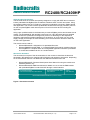
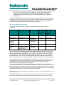
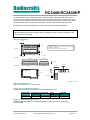
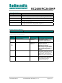
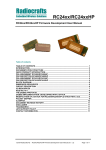
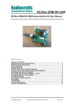
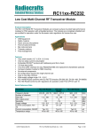
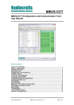
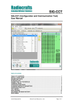
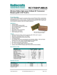
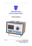
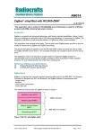
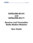
Radiocrafts
Embedded Wireless Solutions
RC2400/RC2400HP
ZigBee®- Ready RF Transceiver Modules
Product Description
The RC2400 and RC2400HP RF Transceiver Modules are a series of compact surfacemounted modules specially designed for the ZigBee® PRO protocol stack. It can also be
used for other for wireless star and mesh networks based on IEEE 802.15.4 compliant PHY
and MAC.
The complete shielded module is only 12.7 x 25.4 x 3.3 mm and comes in both a low current
variant (RC2400) and a High Power version with LNA and power amplifier for extended range
(RC2400HP). The two variants are pin compatible.
Applications
• Smart Metering / AMR / AMI
• Electricity, gas, water and heat meters
• Energy Service Portal (ESP) / Load Control
• IP sensor networks (6LoWPAN)
• RF4CE remote controls
• Wireless sensor networks/Building Automation
Features
• Complete ZigBee-ready module
• 100mW / 20 dBm option and low-power option in pin compatible packages
• 12.7 x 25.4 x 2.5 mm compact shielded module for SMD mounting
• IEEE 802.15.4 compliant PHY
• Single-cycle high performance 8051 microcontroller core
• 256 kB Flash memory, 8 kB SRAM
• 15 digital and analogue I/Os, 8 channel 12 bit ADC
• UART, SPI and debug interfaces
• On-board 32.768 kHz real time clock (RTC), 4 timers
• High performance direct sequence spread spectrum (DSSS) RF transceiver
• 2.0 – 3.6 V supply voltage, ultra low power modes
• Optional 4 kB internal EEPROM
• Conforms with EN 300 440 and EN 300 328 (Europe), FCC CFR 47 part 15 (US),
ARIB STD-T66 (Japan) and G.S.R. 542(E)/45(E) (both for India)
Quick Reference Data
Parameter
Frequency band
Number of channels
Data rate
Max output power
Sensitivity (PER 1%)
Adjacent Channel Rejection
Alternate Channel Rejection
Supply voltage
Current consumption, RX/TX
Current consumption, PD
Flash memory
RAM
Internal EEPROM (optional)
Operating Temperature
©2010 Radiocrafts AS
RC2400
RC2400HP
2.400-2.4835
16
250
4
20
-97
-99
35
49
2.0 - 3.6
2.7 - 3.6
24/34
27/175
0.4
1.3
256
8
4
-30 to +85
(-40 to +85 available on request)
RC2400/RC2400HP Data Sheet (rev. 1.0)
Unit
GHz
kbit/s
dBm
dBm
dB
dB
Volt
mA
uA
kB
kB
kB
°C
Page 1 of 13
Radiocrafts
Embedded Wireless Solutions
RC2400/RC2400HP
Quick Product Introduction
The RC2400 series of modules are specially designed to comply with IEEE 802.15.4-based
industry standards like ZigBee PRO, 6LoWPAN, Wireless HART, RC4CE and others. Using
the module together with the TI Z-stack is a powerful combination to build any ZigBee profile
and application. The module contains qualified RF hardware and enough processor power to
run the complete ZigBee mesh network protocol for a full function device including the
application.
Using a pre-qualified module is the fastest way to make a ZigBee product and shortest time to
market. The embedded RF HW and MCU resources in a 100% RF tested and pre-qualified
module shorten the qualification and approval process. No RF design or RF expertise is
required to add powerful wireless networking to the product. In most cases you only need
supply voltage (for example an external battery) and a sensor/actuator and the module can
run the entire application.
The module can be used as
• RC2400/RC2400HP: HW platform. No preloaded firmware.
• RC2400-ZNM/RC2400HP-ZNM : A complete ZigBee PRO network module where the
entire ZigBee Pro compliant stack and configurable application software is preloaded
in module and available via API on a serial interface.
About this document
This document is one part of the documentation for the module. It describes the electrical
parameters, RF performance, footprint and PCB layout and regulatory information. Depending
on the selected FW solution one additional User Manual should be used. See
•
•
RC2400/RC2400HP Firmware Development User Manual for using the module as a
hardware platform only
RC2400/RC2400HP-ZNM User Manual for details on how to use the ZNM module
with preloaded ZigBee Pro stack and API through a serial interface.
RC2400/RC2400HP
Firmware Development User Manual
RC2400/RC2400HP-ZNM
User Manual
Future
User Manuals
RC2400/RC2400HP Datasheet (This document)
Figure 1 Document structure
©2010 Radiocrafts AS
RC2400/RC2400HP Data Sheet (rev. 1.0)
Page 2 of 13
Radiocrafts
Embedded Wireless Solutions
RC2400/RC2400HP
Pin Assignment
Pin Description
Pin no Pin name
1
GND
2
Digital I/O
3
Digital I/O
4
Digital I/O
5
Digital I/O
6
Digital I/O
7
GND
8
GND
9
RF
10
GND
11
NC
12
Reset
13
VCC
14
GND
Description
System ground
Digital I/O
Digital I/O
Digital I/O
Digital I/O
Digital I/O
System ground
System ground
RF I/O connection to antenna
System ground
Not Connected
Reset. Active Low
Supply voltage input. Internally regulated.
System ground
15
Digital I/O/LNA Gain control for RC2400HP
16
17
18
19
20
21
22
23
24
25
26
27
28
29
30
Digital I/O/
LNA Gain mode
Digital I/O
Digital I/O
Digital I/O
Digital I/O /DD
Digital I/O
Digital I/O
Digital I/O
LNA_Enable
Digital I/O /32kHz_Q1
Digital I/O /32kHz_Q2
Digital I/O
Digital I/O
Digital I/O
Digital I/O
Digital I/O
PA_Enable
Digital I/O
Digital I/O
Digital I/O
Digital I/O
Digital I/O. Debug interface is used for programming.
Digital I/O. Debug interface is used for programming.
Digital I/O
Digital I/O /LNA Enable for RC2400HP
Internal 32 kHz oscillator. Do not connect. (Digital I/O if no xtal)
Internal 32 kHz oscillator. Do not connect. (Digital I/O if no xtal)
Digital I/O
Digital I/O
Digital I/O
Digital I/O
Digital I/O /PA Enable for RC2400HP
Digital I/O
Note 1: For detailed pin description, see respective User Manual
Note 2: Pins 17 and 18 are suggested as I2C interface. They can be configured otherwise, but are connected to an
optional internal EEPROM with I2C address = 000. It is recommended to leave these pins as I2C. Sensors and
actuators or any other I2C device can be connected to these pins and accessed from the module.
©2010 Radiocrafts AS
RC2400/RC2400HP Data Sheet (rev. 1.0)
Page 3 of 13
Radiocrafts
Embedded Wireless Solutions
RC2400/RC2400HP
Block Diagram
RC2400HP
Communication
controller
PA
RF
Transceiver
Low noise
amplifier,
LNA
EEPROM
(Option)
Programming and debugging Interface
For downloading firmware to the module it is required to include a 2x5 pins programming
connector to the modules programming pins. The connector should be a 2.54 mm pitch pin-row
(same pitch in both directions), SMD or through-hole version, with the following connections:
GND 1
2 To VCC
Pin 20 3
4 Pin 19
Pin 12, RESET 7
RF Frequency, Output Power Levels and Data Rates
The following table shows the RF channels as defined by the IEEE 802.15.4 standard.
RF channel
11
12
13
14
15
16
17
18
19
20
21
22
23
24
25
26
Frequency
2405 MHz
2410 MHz
2415 MHz
2420 MHz
2425 MHz
2430 MHz
2435 MHz
2440 MHz
2445 MHz
2450 MHz
2455 MHz
2460 MHz
2465 MHz
2470 MHz
2475 MHz
2480 MHz
For proprietary solutions (non-IEEE 802.15.4), the RF transceiver can be programmed in
steps of 1 MHz.
©2010 Radiocrafts AS
RC2400/RC2400HP Data Sheet (rev. 1.0)
Page 4 of 13
Radiocrafts
Embedded Wireless Solutions
RC2400/RC2400HP
The RF transceiver uses direct sequence spread spectrum (DSSS) with 2 Mchip/s chip rate,
giving a raw data rate of 250 kbit/s. The modulation format is Offset – Quadrature Phase Shift
Keying (O-QPSK). The DSSS makes the communication link robust in noisy environments,
which is beneficial when sharing the same frequency band with other applications.
Output power
The output power can be programmed in a 25-27 dB range. Maximum power setting
(TXPOWER=0xF5) gives 20 dBm output power for RC2400HP and 4 dBm output power for
RC2400. Battery lifetime considerations and compliance to local maximum output power
regulations will influence the output power setting...
Battery operation might require lower peak currents and hence reduced output power,
especially for the RC2400HP. See table below.
Typical values for RC2400HP at 25ºC, 3.3V, Freq = 2440 MHz, 50 ohm matched antenna
impedance.
Power setting
(TXPOWER)
0xF5
0xE5
0xD5
0xC5
0xB5
0xA5
0x95
0x85
0x75
0x65
©2010 Radiocrafts AS
Output power
(dBm)
20,3
19,5
18,8
18,1
17,2
16,2
14,5
13,5
12,0
10,5
Peak current
(mA)
218
192
174
160
145
134
121
112
99
93
RC2400/RC2400HP Data Sheet (rev. 1.0)
Page 5 of 13
Radiocrafts
Embedded Wireless Solutions
RC2400/RC2400HP
Regulatory Compliance Information
The use of RF frequencies and maximum allowed transmitted RF power is limited by national
regulations. The RC2400HP has been designed to comply with world wide regulations
(R&TTE directive 1999/5/EC in Europe FCC, ARIB and G.S.R. 542(E)/45(E) for India). The
RC2400 (non-HP) complies to all directives and regulations at any power lever setting. In
order to comply with the different standards, the output power for RC2400HP should be
configured as commented below.
R&TTE directive (EU)
According to R&TTE directive it is the responsibility of Radiocrafts’ customers to
check that the host product (i.e. final product) is compliant with R&TTE essential
requirements. The use of a CE marked radio module can avoid re-certification of the
final product, provided that the end user respects the recommendations established
by Radiocrafts. A Declaration of Conformity is available from Radiocrafts on request.
In terms of R&TTE the RC2400HP is a wideband radio and must comply with EN
300 328 on those premises. This implies that the radiated power must be lower than
12 dBm and hence power setting giving 12 dBm or lower can be used in compliance
to EN 300 328.
FCC compliance (US, Canada)
The RC2400HP has been tested towards FCC regulations for license free operation
under part 15. However, a final approval is required by FCC for the end product.
The antenna and duty cycling will determine the output power setting for FCC
compliance. The radiated power of harmonics signals in the FCC termed “restricted
bands” shall be limited to 500uV/m at 3m, which can be estimated to -41,2 dBm
conducted. However, this estimation is based on a 0 dBi antenna for even out-ofband frequencies and 100% TX duty cycling, neither of which are likely.
The requirement can be relaxed based on the TX duty cycling within 100 ms. A IEEE
802.15.4 packet is maximum 5 ms long and hence transmission of 1 packet within
100 ms gives 5% TX duty cycle. According to FCC, then the reduction in requirement
= 20 x log (TX_time_per _100ms / 100ms). Max reduction is 20 dB.
50 % TX duty cycle = 6 dB reduction
25 % TX duty cycle = 12 dB reduction
10 % TX duty cycle = 20 dB reduction
The highest channel (16 = 2480MHz) must be given extra attention as the adjacent
channel power falls in the FCC restricted band 2483.5- 2500MHz. This will limit the
output power on this channel to setting 0xA5 (16.2 dBm), with 100% TX duty cycle.
Requirement is relaxed by reducing the TX duty cycle as explained above,and enable
power setting up to 0xE5 (19.5 dBm).
WPC compliance (India)
License based operation in India is based on case by case grant and the basis is
often a compliance to the R&TTE directive or to FCC.
ARIB compliance
The RC2400HP has been designed to comply with the requirements given by the
Japanese ARIB STD-T66 for low power (short range) devices in the 2.4GHz range.
©2010 Radiocrafts AS
RC2400/RC2400HP Data Sheet (rev. 1.0)
Page 6 of 13
Radiocrafts
Embedded Wireless Solutions
RC2400/RC2400HP
However, it has not been formally assessed for conformity with the appropriate
regulations. Users must assess and verify that their final product meets the
appropriate specifications and to perform the required procedures for regulatory
compliance.
The relevant regulations are subject to change. Radiocrafts AS do not take responsibility for
the validity and accuracy of the understanding of the regulations referred above. Radiocrafts
only guarantee that this product meets the specifications in this document. Radiocrafts is
exempt from any responsibilities related to regulatory compliance.
Antenna and Range Considerations
The module needs an antenna to operate. The following antenna options could be
considered.
Antenna
Advantage
PCB, quarter
wave monopole
PCB Pifa
Low cost,
easy to implement
Low cost
Chip antenna
(7x2mm
example)
External whip
monopole
External whip
dipole
Small size
High performance
High preformance,
no large ground
plane required
Disadvantage
Estimated
LOS range
(meters)
RC2400
250-400
Estimated
LOS range
(meters)
RC2400HP (100
mW)
2000-2500
Sensitive to
surroundings
Medium
preformance
300-500
2500-3000
200-300
1500-2000
Physically large,
higher cost
Physically large,
higher cost
500-700
3000-4000
500-700
3000-4000
Using an antenna, the VSWR (Voltage Standing Wave Ratio) of the antenna should be less
than 2:1. The VSWR is normally specified in the antenna datasheet and most commercial
available antennas fulfil this requirement. If you design a PCB antenna this is an important
input requirement for such a design. Using a VSWR higher than 2:1, will result in unwanted
reflected power into the module and reducing both the module performance and radiated
power. This will in turn reduce the range. Using a VSWR higher than 3:1 is not recommended.
The antenna shall be connected to the RF pin. The RF pin is matched to 50 Ohm. In the case
that an antenna connector for an external antenna is placed away from the module at the
motherboard, the trace between the RF pin and the connector should be a 50 Ohm
transmission line. Follow these general guidelines;
On a two layer board made of FR4 the width of the routing trace, from the RF-pin to any
connector or contact point for a PCB-antenna, should be 1.8 times the thickness of the board,
assuming a dielectric constant of 4.8 (normal value for a FR-4 board). The line should be run
at the top of the board and on the bottom side there should be a ground plane. This will give a
transmission line with close to 50 ohm characteristic impedance.
Example: For a 1.6 mm thick FR4 board, the width of the trace on the top side should be 1.8 x
1.6 mm = 2.88 mm.
The easiest antenna to use is the quarter wave whip antenna. A quarter wave whip antenna
above a ground plane yields 37 Ohm impedance and a matching circuit for 50 Ohm is not
©2010 Radiocrafts AS
RC2400/RC2400HP Data Sheet (rev. 1.0)
Page 7 of 13
Radiocrafts
Embedded Wireless Solutions
RC2400/RC2400HP
required. A quarter wave antenna implemented with a piece of wire normal to the ground
plane should have a length equivalent to 95% of the free space wavelength.
A PCB antenna can be made as a copper track where the ground plane is removed on the
back side. The rest of the PCB board should have a ground plane as large as possible,
preferably as large (in one dimension) as the antenna itself, to make it act as an electrical
counterweight to the antenna. A quarter wavelength antenna on a PCB must be shorter than
the wire antenna due to the influence of the dielectric material of the PCB. The length
reduction depends on the PCB thickness and material, as well as how close to the edge of
the board the antenna is placed. Typical reduction is to 75-90 % of the length in free space
but exact length must be found empirically. A 1.0 or 1.6 mm FR4 PCB with the antenna trace
> 1 cm from conducting obstacles normally reduces the length of a quarter wave antenna to
about 2.4 cm.
If, for space reasons, the track is made even shorter than the resonating quarter of a
wavelength, the antenna should be matched to 50 ohms using a series inductor and a shunt
capacitor.
The length of a quarter-wave antenna is given in the table below.
Frequency
[MHz]
2450
Length of
whip antenna
[cm]
2.9
Length of
PCB track
[cm]
2.25 – 2.7
PCB Layout Recommendations
The recommended layout pads for the module are shown in the figure below. All dimensions
are in thousands of an inch (mil). The circle in upper left corner is an orientation mark only,
and should not be a part of the copper pattern.
A PCB with two or more layers and with a solid ground plane in one of the inner- or bottom
layer(s) is recommended. All GND-pins of the module shall be connected to this ground plane
with vias with shortest possible routing, one via per GND-pin.
©2010 Radiocrafts AS
RC2400/RC2400HP Data Sheet (rev. 1.0)
Page 8 of 13
Radiocrafts
Embedded Wireless Solutions
RC2400/RC2400HP
On the back side of the module there are several test pads. These test pads shall not be
connected, and the area underneath the module should be covered with solder resist. If any
routing or vias is required under the module, the routing and vias must be covered with solder
resist to prevent short circuiting of the test pads. It is recommended that vias are tented.
Reserved pins should be soldered to the pads, but the pads must be left floating.
Note that Radiocrafts technical support team is available for free-of-charge schematic- and
layout review of your design.
Mechanical Drawing
1.9 mm
m
m
9
.
1
Radiocrafts
Part nr: RCXXXX
Lot code: YYYYWW (YYYY=prod. year, WW= prod. week)
Hardware revision: A.BB
Approval marking: NN = CE, FCC or others
Top view
RCXXXX
NN
YYYYWW
A.BB
m
m
.2
3
End view
3.2 mm
Side view
10.9 mm
23.6 mm
3.3 mm
0.38 mm
25.4 mm
Bottom view
12.7 mm
2.1 mm
1.4 mm
2.1 mm
8.5 mm
0.9 mm
13.6 mm
Drawings are not to scale
Mechanical Dimensions
The module size is 12.7 x 25.4 x 3.3 mm.
Carrier Tape and Reel Specification
Carrier tape and reel is in accordance with EIA Specification 481.
Tape width
44 mm
Component Hole pitch
pitch
16 mm
4 mm
Reel
diameter
13”
Units per
reel
Max 1000
Soldering Profile Recommendation
JEDEC standard IEC/JEDEC J-STD-020B (page 11 and 12), Pb-Free Assembly is
recommended.
©2010 Radiocrafts AS
RC2400/RC2400HP Data Sheet (rev. 1.0)
Page 9 of 13
Radiocrafts
Embedded Wireless Solutions
RC2400/RC2400HP
The standard requires that the heat dissipated in the "surroundings" on the PCB is taken into
account. The peak temperature should be adjusted so that it is within the window specified in
the standard for the actual motherboard.
Aperture for paste stencil is normally areal-reduced by 20-35%, please consult your
production facility for best experience aperture reduction. Nominal stencil thickness of 0.10.12 mm recommended.
Absolute Maximum Ratings
Parameter
Min
Supply voltage, VCC
-0.3
Voltage on any pin
-0.3
Input RF level
Storage temperature
-40
Operating temperature
-30
Max
3.6
VCC+0.5
10
85
85
Unit
V
V
dBm
°C
°C
Caution ! ESD sensitive device.
Precaution should be used when handling
the device in order to prevent permanent
damage.
Under no circumstances the absolute maximum ratings given above should be violated.
Stress exceeding one or more of the limiting values may cause permanent damage to the
device.
Electrical Specifications
T=25°C, VCC = 3.3V, 50 ohm if nothing else stated.
Parameter
Min
Typ.
Operating frequency
2400
Max
2483
Unit
MHz
Number of channels
16
Channel spacing
5
MHz
Input/output impedance
50
Ohm
Data rate
250
kbit/s
2
Mc/s
DSSS chip rate
Frequency stability
Transmit power
RC2400
RC2400HP
Harmonics
RC2400
nd
2 harmonic
rd
3 harmonic
RC2400HP (19 dBm Pout)
nd
2 harmonic
rd
3 harmonic
For IEEE 802.15.4 compliance
+/-40
Programmable from firmware
4
20
Compliance to FCC requires
less than - 27 dBm given TX
duty cycle of 20% and 0dBi
antenna gain at harmonic
frequencies.
-35
-35
-32
-40
Spurious emission
RC2400HP, TX, 20 dBm
30 – 1000 MHz
1-12.75 GHz
-50
-45
RC2400 TX, 4 dBm
30 – 1000 MHz
-56
©2010 Radiocrafts AS
For IEEE 802.15.4 compliance
ppm
dBm
-23
-6
Condition / Note
Programmable in 1 MHz steps,
5 MHz steps for IEEE 802.15.4
compliance
dBm
Complies with EN 300 328, EN
300 440, FCC CRF47 Part 15
and ARIB STD-T66
RC2400/RC2400HP Data Sheet (rev. 1.0)
Page 10 of 13
Radiocrafts
Embedded Wireless Solutions
Parameter
1-12.75 GHz
1.8-1.9 GHz
5.15-5.3 GHz
Sensitivity
RC2400
RC2400HP
Adjacent channel rejection
+/- 5 MHz
Unit
Condition / Note
dBm
PER = 1%
35
dB
At -82 dBm, PER = 1%.
0 dB for IEEE 802.15.4
compliance
Alternate channel selectivity
+/- 10 MHz
+/- 20 MHz
49
56
dB
At -82 dBm, PER = 1%.
30 dB for IEEE 802.15.4
compliance
Saturation
10
dBm
Spurious emission, RX
30 -1000 MHz
1-12.75 GHz
Supply voltage
RC2400
RC2400HP
Min
RC2400/RC2400HP
Typ.
-97
-99
-57
-47
Current consumption, TX
RC2400, 4dBm
RC2400HP, 19 dBm
34
175
Antenna VSWR
©2010 Radiocrafts AS
Complies with EN 300 328, EN
300 440, FCC CRF47 Part 15
and ARIB STD-T66
3.6
3.6
27
RAM memory
MCU clock frequency
MCU low frequency crystal
dBm
V
2.0
2.7
Current consumption, RX
Current consumption, Power
down
RC2400
RC2400HP
Max
-48
-53
-60
mA
mA
µA
MCU in Idle mode using the 32
MHz oscillator.
MCU in Idle mode using the 32
MHz oscillator.
Wake-up time to power mode 0
is 54 uS
0.4
1.3
8
32
32.768
<2:1
kB
MHz
kHz
3:1
RC2400/RC2400HP Data Sheet (rev. 1.0)
Page 11 of 13
Radiocrafts
Embedded Wireless Solutions
Ordering Information
Ordering Part Number
RC2400
RC2400HP
RC2405
RC2405HP
RC2400-ZNM
RC2400HP-ZNM
RC2400/RC2400HP
Description
ZigBee-ready RF module, 256 kB Flash
ZigBee-ready RF module, 256 kB Flash. High power, long range
ZigBee-ready RF module, 256 kB Flash, including EEPROM
ZigBee-ready RF module, 256 kB Flash. High power, long range,
including EEPROM
ZigBee-ready RF module, embedded ZigBee stack with API
through serial interface
ZigBee-ready RF module, embedded ZigBee stack with API
through serial interface. High power, long range
Document Revision History
Document Revision
Changes
1.0
First release
Product Status and Definitions
Current
Data Sheet Identification
Status
Product Status
Advance Information
Planned or under
development
Preliminary
Engineering
Samples and First
Production
No Identification Noted
Full Production
Obsolete
Not in Production
X
©2010 Radiocrafts AS
Definition
This data sheet contains the design
specifications for product
development. Specifications may
change in any manner without notice.
This data sheet contains
preliminary data, and
supplementary data will be
published at a later date.
Radiocrafts reserves the right to
make changes at any time without
notice in order to improve design
and supply the best possible
product.
This data sheet contains final
specifications. Radiocrafts reserves
the right to make changes at any time
without notice in order to improve
design and supply the best possible
product.
This data sheet contains
specifications on a product that has
been discontinued by Radiocrafts.
The data sheet is printed for
reference information only.
RC2400/RC2400HP Data Sheet (rev. 1.0)
Page 12 of 13
Radiocrafts
Embedded Wireless Solutions
RC2400/RC2400HP
Disclaimer
Radiocrafts AS believes the information contained herein is correct and accurate at the time of this printing. However,
Radiocrafts AS reserves the right to make changes to this product without notice. Radiocrafts AS does not assume
any responsibility for the use of the described product; neither does it convey any license under its patent rights, or
the rights of others. The latest updates are available at the Radiocrafts website or by contacting Radiocrafts directly.
As far as possible, major changes of product specifications and functionality, will be stated in product specific Errata
Notes published at the Radiocrafts website. Customers are encouraged to check regularly for the most recent
updates on products and support tools.
Trademarks
RC232™ is a trademark of Radiocrafts AS. The RC232™ Embedded RF Protocol is used in a range of products from
Radiocrafts. The protocol handles host communication, data buffering, error check, addressing and broadcasting. It
supports point-to-point, point-to-multipoint and peer-to-peer network topologies.
All other trademarks, registered trademarks and product names are the sole property of their respective owners.
Life Support Policy
This Radiocrafts product is not designed for use in life support appliances, devices, or other systems where
malfunction can reasonably be expected to result in significant personal injury to the user, or as a critical component
in any life support device or system whose failure to perform can be reasonably expected to cause the failure of the
life support device or system, or to affect its safety or effectiveness. Radiocrafts AS customers using or selling these
products for use in such applications do so at their own risk and agree to fully indemnify Radiocrafts AS for any
damages resulting from any improper use or sale.
© 2010, Radiocrafts AS. All rights reserved.
Contact Information
Web site: www.radiocrafts.com
Email: [email protected]
Address:
Radiocrafts AS
Sandakerveien 64
NO-0484 OSLO
NORWAY
Tel:
+47 4000 5195
Fax:
+47 22 71 29 15
E-mail: [email protected]
[email protected]
©2010 Radiocrafts AS
RC2400/RC2400HP Data Sheet (rev. 1.0)
Page 13 of 13