1
om
.c
ua
ls
Operating Instructions
ww
w
.E
lec
tri
ca
lP
ar
tM
an
SIMOVERT Master Drives
Servo Control (SC)
Types A to D
AC-AC
Edition: B
Order-No.:6SE7087-6AD30
01.95
om
General
These Operating Instructions are available in the following languages:
German
French
Spanish
Italian
Order-No.
6SE7080-0AD30
6SE7087-7AD30
6SE7087-8AD30
6SE7087-2AD30
.E
lec
tri
ca
lP
ar
tM
an
ua
ls
.c
Language
w
The reproduction, transmission or use of this document or its
contents is not permitted without express written authority.
Offenders will be liable for damages. All rights, including rights
created by patent grant or registration of a utility model or design,
are reserved.
ww
We have checked the contents of this document to ensure that
they coincide with the described hardware and software.
However, differences cannot be completely excluded, so that we
do not accept any guarantee for complete conformance.
However, the information in this document is regularly checked
and necessary corrections will included in subsequent editions.
We are grateful for any recommendations for improvement.
Siemens AG 1995 All rights reserved
SIMOVERT Registered Trade Mark
01.95
General
om
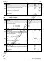
Contents
Definitions................................................................................................................................. 0-7
1
Description................................................................................................................................ 1-1
1.1
Applications ................................................................................................................................ 1-1
1.2
Mode of operation ...................................................................................................................... 1-1
2
Transport, Unpacking, Installation ......................................................................................... 2-1
2.1
Transport and unpacking............................................................................................................ 2-1
2.2
Storage....................................................................................................................................... 2-1
2.3
Mounting..................................................................................................................................... 2-2
2.4
Dimension drawings ................................................................................................................... 2-3
3
Connecting-up .......................................................................................................................... 3-1
3.1
3.1.1
3.1.2
Power connections ..................................................................................................................... 3-4
Protective conductor connection ................................................................................................ 3-5
DC link connection...................................................................................................................... 3-5
3.2
Auxiliary power supply/main contactor ....................................................................................... 3-7
3.3
3.3.1
3.3.2
3.3.3
3.3.4
Control terminal strip and serial interface ................................................................................... 3-8
Connectors for the control terminal strip..................................................................................... 3-8
Connecting-up the control cables ............................................................................................... 3-9
Terminal connection ................................................................................................................. 3-10
Connecting-up the parameterizing unit (PMU) ......................................................................... 3-12
3.5
4
ua
ls
an
ar
tM
lP
ca
lec
tri
3.4
.c
0
Measures to maintain the radio interference suppression regulations ..................................... 3-13
Recommended circuit............................................................................................................... 3-14
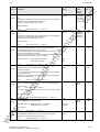
Start-up...................................................................................................................................... 4-1
Introduction and handling start-up .............................................................................................. 4-1
Handling the start-up instructions ............................................................................................... 4-1
General explanation of the terminology and functional scope of the converter.......................... 4-1
.E
4.1
4.1.1
4.1.2
First start-up ............................................................................................................................... 4-3
Preparatory measures................................................................................................................ 4-3
Motor list ..................................................................................................................................... 4-4
Parameterization "Standard application with V/f characteristic without hardware options" ........ 4-6
Parameterization "expert application"......................................................................................... 4-7
Simplified block diagrams for setpoint channel and closed-loop control .................................. 4-10
Simple application examples for connecting process data with connection assignment.......... 4-11
4.3
4.3.1
4.3.1.1
Start-up aids ............................................................................................................................. 4-12
Process data............................................................................................................................. 4-12
Control word (control word 1 and control word 2) .................................................................... 4-12
ww
w
4.2
4.2.1
4.2.1.1
4.2.2
4.2.3
4.2.4
4.2.5
Siemens AG 6SE7087-6AD30
SIMOVERT Master Drives Operating Instructions
0-3
General
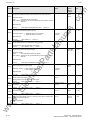
4.4
Function Diagrams ................................................................................................................... 4-49
5
.c
ua
ls
an
ar
tM
lP
General Observation Parameters............................................................................................... 5-2
5.2
General Parameters ................................................................................................................... 5-4
Drive Data................................................................................................................................... 5-5
.E
5.3
5.5
ca
Parameter List........................................................................................................................... 5-1
5.1
5.4
om
4.3.11
Introduction and application example ....................................................................................... 4-12
Overview of the control word (control word 1 and control word 2) ........................................... 4-14
Selecting the source for control word 1 (bits 0-7) .................................................................... 4-15
Selecting the source for control word 1 (bits 8-15) .................................................................. 4-16
Selecting the source for control word 2 (Bit 16-23) ................................................................. 4-17
Selecting the source for control word 2 (bits 24-31) ................................................................ 4-18
Significance of control word- (1 and 2) commands .................................................................. 4-19
Status word (status word 1 and status word 2) ........................................................................ 4-24
Introduction and application example ....................................................................................... 4-24
Overview of the status word (status word 1 and status word 2) ............................................... 4-26
Selecting the destinations for the status word (bits 0 - 31) ....................................................... 4-27
Significance of the status word messages................................................................................ 4-28
Setpoints................................................................................................................................... 4-31
Actual values ............................................................................................................................ 4-32
Binary inputs............................................................................................................................. 4-33
Binary outputs........................................................................................................................... 4-33
Analog input.............................................................................................................................. 4-34
Analog output ........................................................................................................................... 4-36
Serial interfaces........................................................................................................................ 4-39
Basic converter interfaces SST1 and SST2 ............................................................................. 4-39
Dual port RAM (DPR for SCB, TSY, CB, TB)........................................................................... 4-40
Ramp-function generator (RFG) and limiting stage in front of the ramp-function generator .... 4-40
Ramp-function generator, RFG ................................................................................................ 4-40
Limit value stage in front of the ramp-function generator ......................................................... 4-41
Function selection (P052) ........................................................................................................ 4-42
Factory setting (P052 = 1) ........................................................................................................ 4-42
Initialization (P052 = 2) ............................................................................................................. 4-43
Download (P052 = 3)................................................................................................................ 4-44
Hardware configuration (P052 = 4) ......................................................................................... 4-44
Drive setting (P052 = 5)............................................................................................................ 4-45
Functions (software) ................................................................................................................. 4-46
Motor identification ................................................................................................................... 4-46
Restart-on-the-fly...................................................................................................................... 4-46
Pulse encoder simulation.......................................................................................................... 4-46
Start-up after first start-up including subsequent enabling of software functions and hardware
options ...................................................................................................................................... 4-47
Capacitor forming ..................................................................................................................... 4-48
lec
tri
4.3.1.1.1
4.3.1.1.2
4.3.1.1.3
4.3.1.1.4
4.3.1.1.5
4.3.1.1.6
4.3.1.1.7
4.3.1.2
4.3.1.2.1
4.3.1.2.2
4.3.1.2.3
4.3.1.2.4
4.3.1.3
4.3.1.4
4.3.2
4.3.3
4.3.4
4.3.5
4.3.6
4.3.6.1
4.3.6.2
4.3.7
4.3.7.1
4.3.7.2
4.3.8
4.3.8.1
4.3.8.2
4.3.8.3
4.3.8.4
4.3.8.5
4.3.9
4.3.9.1
4.3.9.2
4.3.9.3
4.3.10
01.95
w
5.6
ww
5.7
Hardware Configuration.............................................................................................................. 5-6
Motor Data.................................................................................................................................. 5-7
Control ........................................................................................................................................ 5-8
Functions .................................................................................................................................. 5-11
5.8
Setpoint Channel ...................................................................................................................... 5-12
5.9
Control and Status Word .......................................................................................................... 5-18
5.10
Analog Input/Output.................................................................................................................. 5-28
0-4
Siemens AG 6SE7087-6AD30
SIMOVERT Master Drives Operating Instructions
General
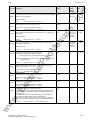
5.11
Communications....................................................................................................................... 5-30
5.12
Diagnosis.................................................................................................................................. 5-34
5.13
Modulator ................................................................................................................................. 5-38
5.14
Factory Parameters.................................................................................................................. 5-39
5.15
Profile Parameters.................................................................................................................... 5-39
6
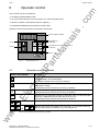
Operator control ....................................................................................................................... 6-1
6.1
Operator control elements.......................................................................................................... 6-1
6.2
Displays
6.3
Structure..................................................................................................................................... 6-3
7
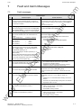
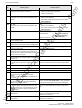
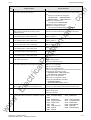
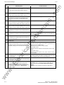
Fault and Alarm Messages ...................................................................................................... 7-1
7.1
Fault messages .......................................................................................................................... 7-1
7.2
Alarm messages......................................................................................................................... 7-6
8
Maintenance.............................................................................................................................. 8-1
8.1
Maintenance requirements ......................................................................................................... 8-1
8.2
8.2.1
8.2.2
8.2.3
8.2.3.1
Replacing components ............................................................................................................... 8-2
Relacing the fan.......................................................................................................................... 8-2
Replacing the fuses (size D)....................................................................................................... 8-2
Replacing boards........................................................................................................................ 8-3
Replacing boards in the electronics box..................................................................................... 8-3
9
Options...................................................................................................................................... 9-1
9.2
9.3
.c
ua
ls
an
ar
tM
lP
ca
Options which can be integrated into the electronics box .......................................................... 9-1
Interface boards ......................................................................................................................... 9-2
Power supplies ........................................................................................................................... 9-2
Isolating amplifiers...................................................................................................................... 9-3
.E
9.4
.................................................................................................................... 6-2
lec
tri
9.1
om
01.95
Power section ............................................................................................................................. 9-3
Output reactor, dv/dt filter, sinusoidal filter ................................................................................. 9-3
9.6
Main-, output contactor............................................................................................................... 9-4
9.7
Operator control ......................................................................................................................... 9-5
9.8
Mechanical design...................................................................................................................... 9-5
ww
w
9.5
9.5.1
9.9
Additional equipment series ....................................................................................................... 9-6
10
Spare Parts ...................................................................................................................................1
Siemens AG 6SE7087-6AD30
SIMOVERT Master Drives Operating Instructions
0-5
General
01.95
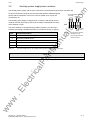
Logbook .................................................................................................................................. 11-1
12
Environmental friendliness ................................................................................................... 12-1
13
Technical Data ........................................................................................................................ 13-1
13.1
De-rating for an increased cooling medium temperature ......................................................... 13-6
13.2
De-rating at installation altitudes > 1000 m above sea level..................................................... 13-6
13.3
De-rating as a function of the pulse frequency ......................................................................... 13-7
14
Index ........................................................................................................................................ 14-1
15
Adressess ............................................................................................................................... 15-1
ww
w
.E
lec
tri
ca
lP
ar
tM
an
ua
ls
.c
om
11
0-6
Siemens AG 6SE7087-6AD30
SIMOVERT Master Drives Operating Instructions
01.95
General
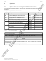
Definitions
om
0
• QUALIFIED PERSONAL
.c
For the purpose of these instructions and product labels, a "Qualified person" is someone who is familiar with
the installation, mounting, start-up and operation of the equipment and the hazards involved. He or she must
have the following qualifications:
1. Trained and authorized to energize, de-energize, clear, ground and tag circuits and equipment in
accordance with established safety procedures.
ua
ls
2. Trained in the proper care and use of protective equipment in accordance with established safety
procedures.
3. Trained in rendering first aid.
• DANGER
For the purpose of these instructions and product labels, "Danger" indicates death, severe personal injury or
substantial property damage will result if proper precautions are not taken.
an
• WARNING
ar
tM
For the purpose of these instructions and product labels, "Warning" indicates death, severe personal injury or
property damage can result if proper precautions are not taken.
• CAUTION
For the purpose of these instructions and product labels, "Caution" indicates that minor personal injury or
material damage can result if proper precautions are not taken.
• NOTE
.E
lec
tri
ca
lP
For the purpose of these instructions, "Note" indicates information about the product or the respective part of
the Instruction Manual which is essential to highlight.
NOTE
w
These instructions do not purport to cover all details or variations in equipment, nor to provide for every
possible contingency to be met in connection with installation, operation or maintenance.
ww
Should further information be desired or should particular problems arise which are not covered sufficiently for
the purchaser’s purposes, the matter should be referred to the local Siemens sales office.
The contents of this Instruction Manual shall not become part of or modify any prior or existing agreement,
committment or relationship. The sales contract contains the entire obligation of Siemens. The warranty
contained in the contract between the parties is the sole warranty of Siemens. Any statements contained herein
do not create new warranties or modify the existing warranty.
Siemens AG 6SE7087-6AD30
SIMOVERT Master Drives Operating Instructions
0-7
General
01.95
om
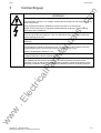
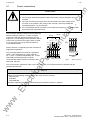
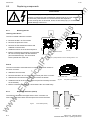
CAUTION
Components which can be destroyed by electrostatic discharge (ESD)
.c
The converters contain components which can be destroyed by electrostatic discharge. These components can
be easily destroyed if not carefully handled. If you have to handle electronic boards please observe the
following:
♦ Electronic boards should only be touched when absolutely necessary.
ua
ls
♦ The human body must be electrically discharged before touching an electronic board
♦ Boards must not come into contact with highly insulating materials - e.g. plastic foils, insulated desktops,
articles of clothing manufactured from man-made fibers
♦ Boards must only be placed on conductive surfaces
♦ When soldering, the soldering iron tip must be grounded
an
♦ Boards and components should only be stored and transported in conductive packaging (e.g.
metalizedplastic boxes, metal containers)
ar
tM
♦ If the packing material is not conductive, the boards must be wrapped with a conductive packaging material,
e.g. conductive foam rubber or household aluminum foil.
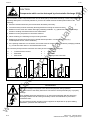
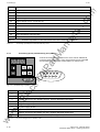
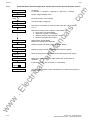
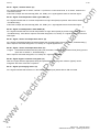
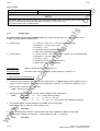
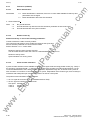
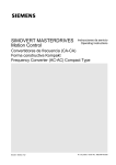
The necessary ECB protective measures are clearly shown in the following diagram:
=
Conductive floor surface
b
=
ESD table
c
=
ESD shoes
f
lec
tri
f
c
ESD overall
e
=
ESD chain
f
=
Cubicle ground connection
ca
e
a
=
d
d
b
d
lP
a
c
a
Standing
Sitting
d
b
e
f
f
f
c
a
Standing / Siting
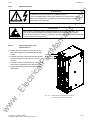
WARNING
.E
Hazardous voltages are present in this electrical equipment during operation.
ww
w
Non-observance of the safety instructions can result in severe personal injury or property
damage.
0-8
Only qualified personnel should work on or around the equipment after first becoming
thoroughly familiar with all warning and safety notices and maintenance procedures
contained herein.
The successful and safe operation of this equipment is dependent on proper handling,
installation, operation and maintenance.
Siemens AG 6SE7087-6AD30
SIMOVERT Master Drives Operating Instructions
01.95
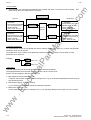
Description
Description
1.1
Applications
om
1
.c
SIMOVERT Master Drive are power electronic units. The converters, described in this Instruction Manual
generate a variable-frequency three-phase system from a three-phase supply network with fixed frequency
(50/60 Hz). This allows AC motors to be continuously speed controlled. There are three different versions
depending on the particular application:
FC
simple applications (e.g. pumps and fans)
♦ Vector control
VC
high demands regarding dynamic performance and accuracy
♦ Servo control
SC
servo drives
ua
ls
♦ Frequency control
In the basic design, SIMOVERT Master Drives can be used for two-quadrant operation. Four-quadrant operation
is possible using the braking unit option. SIMOVERT Master Drives are suitable for single-motor- and multi-motor
drives.
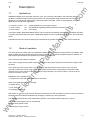
1.2
Mode of operation
ar
tM
an
Expanded functions for certain technological requirements are possible via defined power section interfaces.
The three-phase AC voltage, fed to the SIMOVERT Master Drives through the input terminals, is rectified in a B6
bridge rectifier and fed to the DC link through series resistors. The DC link is charged through two resistors, so
that complete ground-fault proof operation is provided on the load side.
lP
The converter is then ready for operation.
ca
The inverter, configured using IGBT modules, generates a three-phase system from the DC link voltage to feed
the motor
lec
tri
The inverter open-loop control uses a microprocessor with field-oriented vector control, with a very fast
secondary closed-loop current control. High drive dynamic performance is achieved as a result of the field
oriented vector control. When the unit is shipped, the pulse frequency is preset to 5 kHz. It can be set in the
range from 5 kHz to 7.5 kHz.
SIMOVERT SC is suitable for:
♦ Single-motor drives with permanent-field 1FT6 motors
Some of the applications are, for example
♦ Winder drives,
.E
♦ Foil machines,
♦ Packaging machines
After power-up, only the motor must be selected and the drive can then be enabled. The drive can be matched to
the load moment of inertia and optimized by changing a closed-loop control parameter.
w
The converter operates with motor identification (MOTID). The maximum stator frequency is 400 Hz.
The following operating modes can be selected:
ww
♦ Closed-loop speed control
♦ Closed-loop torque control
Siemens AG 6SE7087-6AD30
SIMOVERT Master Drives Operating Instructions
1-1
Description
01.95
The following encoders can be used:
om
♦ ERN 1387 encoders
♦ Encoders which are compatible to ERN 1387
♦ Resolvers
.c
The converter can be controlled via
♦ the parameterization unit (PMU)
♦ an optional operator control panel (OP1)
♦ terminal strip
ua
ls
♦ a serial interface.
ww
w
.E
lec
tri
ca
lP
ar
tM
an
When networked with automation systems, the converter open-loop control is realized via optional interfaces and
technology boards.
1-2
Siemens AG 6SE7087-6AD30
SIMOVERT Master Drives Operating Instructions
01.95
Transport, Unpacking, Installation
Transport, Unpacking, Installation
2.1
Transport and unpacking
om
2
Vibration and jolts must be avoided during transport, e.g. when setting the unit down.
.c
SIMOVERT Master Drives are packed in the manufacturing plant corresponding to that specified when ordered.
A product packing label is provided on the carton.
ua
ls
Please observe the instructions on the packaging for transport, storage and professional handling.
The converter can be installed after it has been unpacked and checked to ensure that everything is
complete and that the converter is not damaged.
If the converter is damaged you must inform your shipping company immediately.
Storage
ar
tM
2.2
an
The packaging comprises board and corrugated paper. It can be disposed of corresponding to the
appropriate local regulations for the disposal of board products.
The converters must be stored in clean dry rooms.Temperatures between − 25 °C (−13 °F) and + 70 °C (158 °F)
are permissible. Temperature fluctuations > 20 K per hour are not permissible.
WARNING
lP
The equipment should not be stored for longer than one year. If it is stored for longer
periods of time, the converter DC link capacitors must be formed at start-up.
ww
w
.E
lec
tri
ca
Forming is described in Section 4.3.12.
Siemens AG 6SE7087-6AD30
SIMOVERT Master Drives Operating Instructions
2-1
Transport, Unpacking, Installation
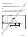
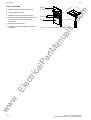
Mounting
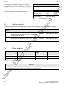
The following are required for mounting:
♦ G busbar according to EN50035 with screws for mounting
♦ One M6 screw for types of construction A to C; two M6 screws for type of construction D
om
2.3
01.95
.c
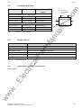
♦ Dimension drawing (Fig. 2.2 for types of construction A, B and C, Fig. 2.3 for type of construction D).
WARNING
ua
ls
Safe converter operation requires that the equipment is mounted and commissioned by
qualified personnel taking into account the warning information provided in this Instruction
Manual.
The general and domestic installation and safety regulations for work on electrical power
equipment (e.g. VDE) must be observed as well as the professional handling of tools and
the use of personnal protective equipment.
an
Death, severe bodily injury or significant material damage could result if these instructions
are not followed.
Requirements at the point of installation:
ar
tM
The unit must be protected against the ingress of foreign bodies as otherwise the function
as well as the operational safety cannot be guaranteed.
The local guidelines and regulations must be observed when mounting and installing the equipment.
Equipment rooms must be dry and dust-free. Ambient and cooling air
Heat dissipation
must not contain any electrically conductive gases, vapors and dusts
which could diminish the functionality. Dust-laden air must be filtered.
lP
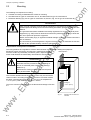
WARNING
ca
When mounting in cabinets, a clearance of above
and below must be provided so that the cooling air
flow is not restricted (refer to dimension drawings,
Section 2.4).
Dimension the cabinet cooling in line with the power
loss! (technical data, Section 13)
lec
tri
6SE70
The converter ambient climate in operating rooms may not exceed the
values of code F according to DIN 40040. The drive converter must be
de-rated, corresponding to Sections 13.1 and 13.2, for temperatures
> 40 °C (104 °F) and installation altitudes > 1000 m.
Cooling air
≤ 40 °C (50 °C)
Fig. 2.1
Mounting the converters in
cabinets
ww
w
.E
The unit is mounted corresponding to the dimension drawings in Section
2.4.
2-2
Siemens AG 6SE7087-6AD30
SIMOVERT Master Drives Operating Instructions
Siemens AG 6SE7087-6AD30
SIMOVERT Master Drives Operating Instructions
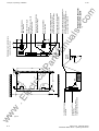
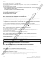
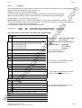
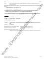
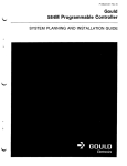
X1
Z
Detail Z
detail Z
d
Schirmanschlagstellen für Signalleitungen (2 Schirmschellen)
Screen connection for two cables.
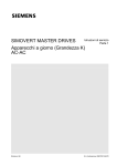
Motoranschlußklemme
Motor terminals
Signalanschlüsse auf der CU
Connectors on CU
e
.c
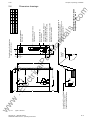
Kompaktgeräte, Bauform A bis C
Compact units, Type A to C
ua
ls
Haken (Aufhängung) zur Befestigung an
einer G-Schiene nach EN50035
Hook (suspension) for mounting on a
g-rail according to EN50035
Durchgangsloch für Schraube M6
Mounting hole for screw M6
d
90 38.5
135 37
180 70
om
a
c
b
Bauform/Type A 425 48.5 45
Bauform/Type B 425 47 67.5
Bauform/Type C 600 70 90
Netzanschlußklemme
Main terminals
an
max. 5.7
c
X2
e
X1
b
ar
tM
lP
ca
270
300
350
X9
X2
X1
X9
lec
tri
.E
Anschluß ext. SV und Hilfsschütz
Connector for ext. power
supply and auxiliary contactor
w
100
a
Darstellung ohne Frontabdeckung
view without front cover
55
Fig. 2.2
250
2.4
55
ww
01.95
Transport, Unpacking, Installation
Dimension drawings
Types A, B and C
2-3
a
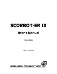
Anschluß ext. SV und
Hilfsschütz
Connector for ext. power
supply and auxiliary contactor
X9
X1
X2
X1
X9
350
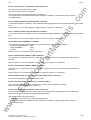
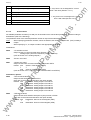
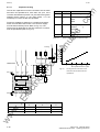
Z
Detail Z
detail Z
X2
60
X1
270
Durchgangsloch für Schraube M6
Mounting hole for screw M6
Schirmanschlagstellen für Signalleitungen (2 Schirmschellen)
Screen connection for two cables.
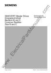
Motoranschlußklemme
Motor terminals
Anpassung Ventilatorspannung
Adjustment fan voltage
Ventilator-Sicherungen
Fan-fuses
Signalanschlüsse auf der CU
Connectors on CU
Netzanschlußklemme
Main terminals
om
.c
Kompaktgeräte, Bauform
Compact units, type D
Haken (Aufhängung) zur Befestigung an
einer G-Schiene nach EN50035
Hook (suspension) for mounting on a
g-rail according to EN50035
ua
ls
an
180
max. 5.7
45
F101 F102
90
Darstellung ohne Frontabdeckung
view without front cover
ar
tM
lP
ca
310
lec
tri
.E
Ventilator-Sicherungen
Fan-fuses
w
100
600
250
90
2-4
600
Fig. 2.3
90
ww
Transport, Unpacking, Installation
01.95
Type D
Siemens AG 6SE7087-6AD30
SIMOVERT Master Drives Operating Instructions
01.95
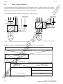
Connecting-up
WARNING
SIMOVERT Master Drives are operated at high voltages.
om
3
Connecting-up
.c
The equipment must be in a no-voltage condition (disconnected from the supply) before any
work is carried-out!
Only professionally trained, qualified personnel must work on or with the unit.
ua
ls
Death, severe bodily injury or significant material damage could occur if these warning
instructions are not observed.
Hazardous voltages are still present in the unit up to 5 minutes after it has been powereddown due to the DC link capacitors. Thus, the appropriate delay time must be observed
before opening-up the unit.
Forming the DC link capacitors:
an
The power terminals and control terminals can still be live even though the motor is
stationary.
The storage time should not exceed one year. The converter DC link capacitors must be
formed at start-up if the unit has been stored for a longer period of time.
ar
tM
Forming is described in Section 4.3.12.
When working on an opened unit, it should be observed that live components (at hazardous
voltage levels) can be touched (shock hazard)
ww
w
.E
lec
tri
ca
lP
The user is responsible, that the motor, converter and any other associated devices or units
are installed and connected-up according to all of the recognized regulations in that
particular country as well as other regionally valid regulations. Cable dimensioning, fusing,
grounding, shutdown, isolation and overcurrent protection should be especially observed.
Siemens AG 6SE7087-6AD30
SIMOVERT Master Drives Operating Instructions
3-1
Connecting-up
01.95
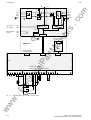
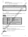
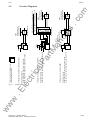
D/L−
X1
X2
U1/L1
V1/L2
U2/T1
V2/T2
W1/L3
W2/T3
PE1
P
M
.c
X9:1
X9:2
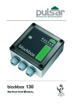
Power suply
ua
ls
Ext. 24 V DC
aux. supply
PE2
24 V
Main contactor
control
om
C/L+
X9:4
X9:5
PEU
X239
X20
SST1 (interface1)
e.g. OP1
an
M
X300
ar
tM
SIMOVERT SC
Internal interface
for option boards
X107
X109
X108
lP
CU
PMU
ca
Control termnal strip
-X100, -X101, -X102, -X103, -X104
X100
X101
X102
X104
X103
26
lec
tri
1 2 3 4 5 6 7 8 9 13 14 15 16 17 18 19 20 21 25 26 27 28 29 35 36 37 38 39 1
.E
SST1
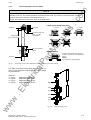
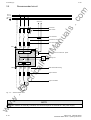
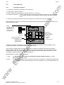
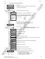
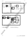
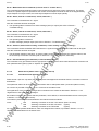
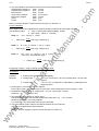
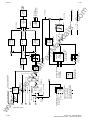
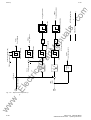
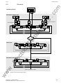
Block diagram, types A, B, and C (24 V DC fan)
ww
w
Fig. 3.1
3-2
Siemens AG 6SE7087-6AD30
SIMOVERT Master Drives Operating Instructions
01.95
Connecting-up
X20
om
F101
M
3
F102
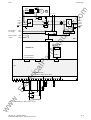
C/L+ D/L-
X19
PCU0
X2
.c
X1
U1/L1
U2/T1
V1/L2
V2/T2
W2/T3
W1/L3
PE1
X9:1
X9:2
Main contactor
control
X9:4
X9:5
P
Netzgerät
Power
suply
M
ua
ls
Ext. 24 V DC
aux. supply
PE2
PEU
an
X239
SST1 (interface1)
e.g. OP1
X300
ar
tM
SIMOVERT SC
PMU
Internal interface
for option boards
X109
X108
lP
X107
ca
CU
lec
tri
Control termnal strip
-X100, -X101, -X102, -X103, -X104
X100
X101
X102
X103
1 2 3 4 5 6 7 8 9 13 14 15 16 17 18 19 20 21 25 26 27 28 29 35 36 37 38 39 1
X104
26
w
.E
SST1
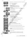
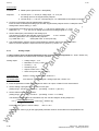
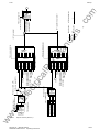
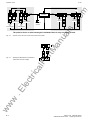
Block diagram, types D (230 V AC fan)
ww
Fig. 3.2
Siemens AG 6SE7087-6AD30
SIMOVERT Master Drives Operating Instructions
3-3
Connecting-up
Power connections
om
3.1
01.95
WARNING
♦ The unit will be destroyed if the input- and output terminals are interchanged!
.c
♦ The converter will be destroyed if the DC link terminals are interchanged or shortcircuited!
♦ The coils of contacts and relays which are connected to the same supply as the
converter or are located in the vicinity of the converter, must be provided with
overvoltage limiters, e.g. RC elements.
The converters should be fused on the line side with
fuses according to Table 3.1. In order to reduce
noise and to limit the harmonics fed back into the
supply a 2 % commutating reactor should be used to
connect the converter to the supply. Refer to Table
3.1 for the Order Nos. for the fuses and the line
commutating reactors.
Supply
W1
C
V1 L3
L+
L2
PE1
D
L-
ar
tM
Refer to Section 3.4 regarding the radio interference
suppression regulations.
DC link
an
U1
L1
ua
ls
♦ It is not permisible that the converter is connected-up through an e.l.c.b. (ground fault
circuit interrupter) (DIN VDE 0160).
X1
The connecting cable cross-sections, specified in
Table 3.1 are determined for copper cable at a
40 ° C (104 ° F) ambient temperature (acc. to DIN
VDE 0298 Part 4/02.88 Group 5) and the
recommended cable protection according to DIN
VDE 0100, Part 430.
Supply connection
U2 V2 W2 PE2
T1 T2 T3
Motor
Fig.3.4
Motor connection
lP
Fig. 3.3
X2
ca
The cross sections, specified in Table 3.2 are the connection cross-sections which are possible with the
particular terminal size.
NOTE
lec
tri
Depending on the motor insulation strength and the length of the motor feeder cable, it may be necessary to
install one of the following options between the motor and the converter:
♦ Output reactor
♦ dv/dt-filter
♦ Sinusoidal filter
ww
w
.E
Information regarding selection and dimensioning is provided in Section 9, "Options".
3-4
Siemens AG 6SE7087-6AD30
SIMOVERT Master Drives Operating Instructions
01.95
Connecting-up
om
NOTE
A transformer is integrated into converters, type of
construction D, due to the 230 V fan. The terminals
on the primary side must be connected
corresponding to the rated input voltage.
Fig. 3.5
Protective conductor connection
Transformer location
(only for converters, type of construction D)
an
3.1.1
ua
ls
Fantransformer
.c
X2
3.1.2
ar
tM
The protective conductor should be connected-up on both the supply- and motor sides. It should be dimensioned
2
according to the power connections. A minimum 10 mm cross-section is required due to the discharge currents
through the noise suppression capacitors.
DC link connection
The− "braking unit" and "dv/dt filter" options can be connected at the DC link terminals X1 C/L+ and X1 D/L.
Voltage
(V)
6SE70
21-3CA30
21-8CB30
22-3CB30
23-2CB30
24-4CC30
VDE
(mm2) AWG1)
(A)
Recommended fuse
gR (SITOR)
(A)
Line reactor
gL NH
VDE
(mm2) AWG
(A)
3NE
Motor
connection
Crosssection
3NA
4EP
208 to 230
10,6
2,5
14
−−− −−−
16
3805
3400-1UK
1,5
16
208 to 230
13,3
4
10
−−− −−−
20
3807
3500-0UK
1,5
16
208 to 230
17,7
6
8
25
1815-0
25
3810
3600-4UK
2,5
14
208 to 230
22,9
10
6
35
1803-0
35
3814
3600-5UK
4
10
208 to 230
32,2
16
4
50
3820
3700-2UK
10
6
208 to 230
44,2
25
2
50
1817-0
63
3822
3800-2UK
16
4
−−− −−−
208 to 230
54
25
2
80
1820-0
80
3824
3900-2UK
25
2
27-0CD30
208 to 230
69
35
0
80
1820-0
80
3824
3900-2UK
25
2
28-1CD30
208 to 230
81
50
00
100
1021-0
100
3830
3900-2UK
35
0
16-1EA30
380 to 460
6,1
1,5
16
−−− −−−
10
3803
3200-1UK
1,5
16
18-0EA30
380 to 460
8,0
1,5
16
−−− −−−
16
3805
3400-2UK
1,5
16
21-0EA30
380 to 460
10,2
2,5
14
−−− −−−
16
3805
3400-1UK
1,5
16
21-3EB30
380 to 460
13,2
2,5
14
25
1815-0
25
3810
3500-0UK
2,5
14
21-8EB30
380 to 460
17,5
4
10
25
1815-0
25
3810
3600-4UK
2,5
14
22-6EC30
380 to 460
25,5
10
6
35
1803-0
35
3814
3600-5UK
10
6
23-4EC30
380 to 460
34
16
4
50
3820
3600-5UK
10
6
23-8ED30
380 to 460
37,5
16
4
63
3822
3700-5UK
16
4
ww
w
.E
25-4CD30
Crosssection
lec
tri
21-1CA30
Curr.
Supply connection
lP
Rated input
ca
Order No.
Siemens AG 6SE7087-6AD30
SIMOVERT Master Drives Operating Instructions
−−− −−−
63
1818-0
3-5
Connecting-up
01.95
Voltage
(V)
Supply connection
Curr.
(A)
Crosssection
Recommended fuse
VDE
(mm2) AWG1)
gR (SITOR)
(A)
6SE70
Line reactor
gL NH
VDE
(mm2) AWG
(A)
3NE
Motor
connection
Crosssection
om
Rated input
3NA
4EP
.c
Order No.
24-7ED30
380 to 460
47
25
2
63
1818-0
63
3822
3800-2UK
16
4
26-0ED30
380 to 460
59
25
2
80
1820-0
100
3830
3800-2UK
16
4
27-2ED30
380 to 460
72
50
00
80
1820-0
100
3830
3900-2UK
25
2
ua
ls
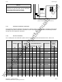
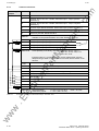
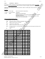
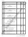
INFORMATION AND EXPLANATIONS
The cables and semiconductors are protected using fuses with gR characteristics. Only the cables, but not the
semiconductors, are protected using gL fuses.
1) American Wire Gauge
2) The specified fuses are valid for converters with a 3-ph AC 500 V input voltage. For converters with higher
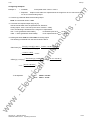
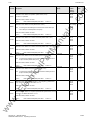
Power connections acc. to DIN VDE and recommended line fuses
A
6SE702_-_ _ _30
2,5 to 10
ar
tM
Table 3.1
an
input voltage, fuses up to 660 V must be used. The Order Nos. of these fuses are obtained by attaching the
suffix "-6" to the appropriate 500 V fuse Order No. e.g.:
3NA3803
=
^ 500 V
3NA3803-6 =
^ 660 V
2,5 to 16
B
6SE702_-_ _ _30
2,5 to 10
12 to 6
2,5 to 16
12 to 4
C
6SE702_-_ _ _30
1 to 16
16 to 4
10 to 25
6 to 2
D
6SE702_-_ _ _30
2,5 to 35
12 to 2
10 to 50
6 to 0
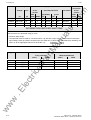
Type
Order No.
Possible connection cross-section
Finely stranded
(mm2)
AWG
12 to 6
12 to 4
ca
Possible connection cross-sections
ww
w
.E
lec
tri
Table 3.2
AWG
lP
(mm2)
Multi-stranded/solid
3-6
Siemens AG 6SE7087-6AD30
SIMOVERT Master Drives Operating Instructions
01.95
Connecting-up
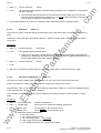
Auxiliary power supply/main contactor
om
3.2
The auxiliary power supply and the main contactor are connected through the 5-pin connector X9.
Connector X9 with the plugs for the control terminal strip are supplied together
(loose) with the equipment. 0.2 mm 2 to 2.5 mm2 (AWG: 24 to 14) can be
connected to X9.
.c
The auxiliary power supply is required if the converter is fed through a main
contactor and the open-loop control functions must be maintained even if the
main contactor is open.
ext. 24 VDC Main contactor
pwr.supp. control
M
P
-X9
1
2
Term.
Fig. 3.6
Function description
24 V DC external ≥ 2,1 A (dependent on the options)
2
Reference potential to DC
3
Unassigned
4
Main contactor control
5
Main contactor control
4
5
AC 230 V
1 kVA
Connecting an external
auxiliary 24 V DC
power supply and main
contactor control
ar
tM
an
1
Table 3.3
ua
ls
The main contactor is controlled through floating contacts -X9.4 and -X9.5
(software pre-setting). Detailed information is provided in Section 9, options.
3
Connector assignment for -X9, auxiliary power supply and main contactor connection
NOTE
ww
w
.E
lec
tri
ca
lP
The main contactor coil must be provided with overvoltage limiters, e.g. RC element (Section 9).
Siemens AG 6SE7087-6AD30
SIMOVERT Master Drives Operating Instructions
3-7
Connecting-up
Control terminal strip and serial interface
om
3.3
01.95
WARNING
.c
The converter must be disconnected and locked-out before control cables are connected to
the CU.
The converter can be controlled via the following interfaces:
ua
ls
♦ Control terminal strip -X101 to -X104 on the electronics board CU
♦ RS 485 serial interface; control terminal strip -X100 on the electronics board CU
♦ OP operator control panel (refer to Section 9, Options)
♦ RS485 and RS232 serial interfaces on the PMU -X300
an
CAUTION
The CU board contains components which can be destroyed by electrostatic discharge.
These components can be very easily destroyed if not handled with caution.
Connectors for the control terminal strip
Labeling
lP
Connector
X100
9-pin, coded
1
2
3
6
7
8
9
X101
9-pin, coded
13
14
15 CU3 18
19
20
21
X102
5-pin
25
26
27
28
29
X103
5-pin
35
36
37
38
39
X104
26-pin
1
lec
tri
The connectors for the control
terminal strip are supplied
(loose) with the unit. Cables with
cross-sections from 0.14 mm2 to
1.5 mm2 (AWG: 26 to 16), or
1 mm2 (AWG: 18) can be
connected, using finely stranded
wire with lugs at the connector
(recommended: 0.5 mm2 (AWG:
20)). The connectors can be
identified using pin numbers
(Table 3.4); the connector
position on the board is
illustrated in Fig. 3.8.
ca
3.3.1
ar
tM
Also refer to the ECB cautionary measures in the Section, General Information.
Table 3.4
CU3
26
Connectors for the control terminal strip are supplied loose
.E
Two screen clamps and four cable ties are required from the loose components supplied to connect the control
cables.
ww
w
The remaining connector X9, included loose with the equipment, is required to control a main contactor and for
connecting an external power supply (refer to Section 3.2 „Auxiliary power supply/main contactor“).
3-8
Siemens AG 6SE7087-6AD30
SIMOVERT Master Drives Operating Instructions
01.95
Connecting-up
Connecting-up the control cables
om
3.3.2
NOTE
The control cables must be screened and should be routed away from the power cables with a minimum
clearance of 20 cm. The screen should be connected at both ends. The screen is connected to the converter
housing using screen clamps - as illustrated in Fig. 3.7.
.c
Control- and cables must cross each other at an angle of 90 °.
Latch screen clamp into place
Cable tie
∅ ≤ 15 mm
Pull-back screen and
retain, e.g. with
shrink tubing
∅ ≤ 5 mm
35
ar
tM
an
Adapt length to
type of construction
∅ ≤ 7.5 mm
ua
ls
Connector
Do not overextend
spring
Connecting-up the control cables and the technique for using the screen clamps
ca
Fig. 3.7
Compress the calamp with your hand
or using a screwdriver and withdraw tow
the top..
Caution!
The clamps have sharp edgesg!
lP
Screening
Release clamp
6SE7090-0XA87-3CA0
6SE7090-0XB87-3CA0
6SE7090-0XC87-3CA0
6SE7090-0XD87-3CA0
ww
w
.E
Order No.:
♦ Type A
♦ Type B
♦ Type C
♦ Type D
lec
tri
The "EMC screened housing" option should be used if so
many control cables are required that two screen clamps
are not sufficient.
Siemens AG 6SE7087-6AD30
SIMOVERT Master Drives Operating Instructions
PMU
-X100
-X101
-X104
-X102
-X103
Fig. 3.8
Control terminals on CU
3-9
Connecting-up
01.95
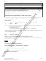
Terminal connection
Connecting
example
Term.
om
3.3.3
Function, notes
-X100
Transmit- and receive line -RS485, differential input / -output, positive
(RS485R/T+)
2
Transmit- and receive line -RS485, differential input / -output, negative
(RS485R/T−)
3
Transmit output RS485 Standard, differential output, positive (RS485T+)
4
Transmit output RS485 Standard, differential output, negative (RS485T−)
5
Reference potential, RS485 interface
ua
ls
.c
1
In addition to the GSST_2 interface on -X100, a GSST_1 interface -X300 is
available on the parameterization unit; refer Section 4 "Start-up“.
NOTE
Binary output, relay 1 (changeover contact) reference contact
7
Binary output, relay 1 (changeover contact) NO contact
8
Binary output, relay 1 (changeover contact) NC contact
9
Binary output, relay 2 (NO contact) reference contact
Load capability of the binary outputs:
60 V AC, 60 VA, cosϕ = 1
60 V AC, 16 VA, cosϕ = 0.4
60 V DC, 24 W
ar
tM
NOTES
an
6
Inductive loads, e.g. contactors, relays, for DC voltage loads, must be
damped using a diode or varistor, and for AC loads, with a varistor or RC
element.
-X101
+24 V, 150 mA for binary inputs and outputs
14
Ref. potential for 24 V (ground)
15
Ref. potential for binary inputs 1 to 7 for ext. signal voltage
16
Binary input 1
17
Binary input 2
18
Binary input 3
ca
lec
tri
19
Binary input 4
20
Binary input 5
21
Binary output, relay 2 (NO contact) NO contact
NOTE
Signal sensitivity
of the binary inputs:
H = 24 V (13 V to 33 V)
L = 0 V (−0,6 V to 3 V)
Imax = 15.7 mA
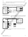
Connecting example for control terminal strips -X100 and -X101
ww
w
.E
Table 3.5
lP
13
3-10
Siemens AG 6SE7087-6AD30
SIMOVERT Master Drives Operating Instructions
01.95
Connecting-up
Term.
Function, notes
om
Connecting
example
-X102
NOTE
.c
28
291)
+10 V / 5 mA, ±2 %, for setpoint pot., non-floating
−10 V / 5 mA, ± 2%, for setpoint pot., non-floating
Analog input 1 (0 V to ±10 V)
Ref. potential, analog input 1
Analog input 1 (0 mA to 20 mA or. 4 mA to 20 mA) int. load resistor 250 Ω
Terminals 33 and 34: To increase the noise immunity of the signals, an
isolating amplifier should be connected between the analog output and
measuring unit for cables > 4 m.
-X103
NOTE
37
38
39
Table 3.6
Analog output 1 ≤ 5 mA
Ref. potential, analog output 1
Terminals 35 and 36: To increase the noise immunity of the signals, an
isolating amplifier should be connected between the analog output and the
measuring unit for cables > 4m.
an
35
36
Output, track A in the HTL level
Output, track B in the HTL level
Output, zero pulse in the HTL level
Connecting-up example for control terminal strips -X102 and -X103
9
1
18
Connecting-up example for control terminal strip -X104
Function, notes
lec
tri
X104
ca
Term.
19
lP
10
26
Fig. 3.9
ar
tM
e.g. meter unit
ua
ls
25
26
271)
Resolver field voltage R1
2
Resolver field voltage R2
3
Track C, Sincos encoders
4
Track C\, Sincos encoders
5
Track D, Sincos encoders
6
Track D\, Sincos encoders
.E
1
0 V sensing line for 5 V encoder
8
Ref. potential for encoder or digital tacho
9
+5 V encoder power supply
10
Output voltage VS1-S3, connection S1
11
Output voltage VS1-S3 connection S3
12
Track A, Sincos encoders
13
Track A\, Sincos encoders
14
Track B, Sincos encoders
15
Track B\, Sincos encoders
ww
w
7
1) Only one of the two terminals, 27 or 29, may be assigned
Siemens AG 6SE7087-6AD30
SIMOVERT Master Drives Operating Instructions
3-11
Connecting-up
Zero pulse, Sincos encoders
17
Zero pulse\, Sincos encoders
18
+ 5 V sense line for 5 V encoders
19
Output voltage VS2-S4, connection S2
20
Output voltage VS2-S4, connection S4
21
Connection for inner screen
22
Connection for inner screen
23
Connection for inner screen
24
Connection for inner screen
25
Motor temperature input (KTY84)
26
Ref. potential for motortemperature
Protective separation for terminals 25 and 26 must be externally guaranteed.
NOTE
an
Connecting-up example for control terminal strip -X104
ar
tM
Table 3.7
.c
16
om
Function, notes
ua
ls
Term.
01.95
3.3.4
Connecting-up the parameterizing unit (PMU)
lP
A serial connection to automation unit or a PC can be realized via
connector X300 on the PMU. Thus, the converter can be controlled
and operated from the central control station or control room.
X300
5
4
ca
P
Fig. 3.10
8
7
2
1
6
lec
tri
9
3
Parameterizing unit (PMU)
PMU -X300 Description
Housing ground
2
Receive line, RS232 standard (V.24)
3
Transmit- and receive line, RS485, two-wire, positive differential input/output
4
RTS (request to send)
5
Ref. potential (ground)
6
5 V power supply for OP
w
.E
1
Transmit line, RS232 standard (V.24)
8
Transmit- and receive line RS485, two-wire, negative differential input/output
ww
7
9
Table 3.8
3-12
Ref. potential for RS232- or RS485 interface (EMC suppressed).
Connector assignment for interface -X300
Siemens AG 6SE7087-6AD30
SIMOVERT Master Drives Operating Instructions
Connecting-up
3.4
Measures to maintain the radio interference suppression regulations
The following points must be observed regarding radio interference suppression regulations
♦ Grounding
om
01.95
.c
Converters generate radio interference noise. This noise should be fed back to the source through the lowest
possible ohmic connection (ground connection cross-section ≥ supply connection cross-section, also refer to
Section 3.1.2)
ua
ls
Use the best grounding possibility (e.g. mounting panel, grounding cable, grounding bar) when installing
converters and optional radio interference suppression filters. Connect all connector housings together
through the largest possible surface area.
For radio interference suppression, the cross-section (observe the safety regulations under fault conditions),
is not so important, but the contact surface, as high-frequency noise currents do not flow through the
complete cross-section, but essentially on the outside surface of a conductor (skin effect).
♦ Screening
an
In order to reduce noise and maintain the radio interference suppression level, the following should be
maintained
• screened cables should be used between the converter output and motor
ar
tM
• screen control cables must be used.
The screen must be connected to ground potential at both ends.
♦ Filter
The radio interference suppression filter and the converter must be mounted directly next to one another on a
metal panel.
ww
w
.E
lec
tri
ca
lP
To maintain the radio interference suppression regulations, radio interference filter B1 should be used.
Siemens AG 6SE7087-6AD30
SIMOVERT Master Drives Operating Instructions
3-13
Connecting-up
Recommended circuit
om
3.5
01.95
.c
U1 / L1
V1 / L2
W1 / L3
PE
Line fuses
ua
ls
230 V AC
Main switch
Line contactor
an
Line filter A1 or B1
PE1
U1/
L1
V1/
L2
W1/
L3
X9:5
X9:4
X9:2
X9:1
C/L+
V2/
T2
W2/
T3
ca
U2/
T1
Braking unit
lec
tri
PE2
Connection for 24 V DC aux. power
lP
D/L-
ar
tM
Line commutating reactor
EMC screened housing
Output reactor
Output contactor
.E
M
3 AC
Recommended circuit
ww
w
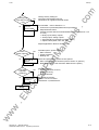
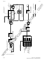
Fig. 3.11
NOTE
If the main contactor is externally controlled, the converter requires an external 24 V DC power supply.
3-14
Siemens AG 6SE7087-6AD30
SIMOVERT Master Drives Operating Instructions
Start-up
Start-up
4.1
Introduction and handling start-up
4.1.1
Handling the start-up instructions
.c
4
om
01.95
NOTE
♦ Section 4.2 First start-up:
First start-up of the converter
ua
ls
♦ Section 4.3 Start-up aids:
Index-type reference for start-up and use of the converter, which must only be used when actually required!
General explanation of the terminology and functional scope of the converter
Abbreviations:
ar
tM
4.1.2
an
♦ Section 4.4 Function diagrams:
Graphical overview of the setpoint channel, open-loop/closed-loop control, analog inputs/outputs, and the
converter data sets
♦ Abbreviations used: Refer to Section 15 "Information, notes"
Converter closed-loop control
♦ Simplified block diagrams in Section 4.2.4
(Detailed "function diagrams, open-loop/closed-loop control": refer to Section 4.4)
♦ Common data:
Speed resolution:
Max. frequency:
♦ Applications:
Permanent-magnet synchronous-motor drives, e.g. for actuator drives, winders, etc.
♦ Control versions:
• Closed-loop speed control
• Closed-loop torque control (entering the torque-generating current).
ww
w
.E
lec
tri
ca
lP
0.3 RPM
400 Hz
Siemens AG 6SE7087-6AD30
SIMOVERT Master Drives Operating Instructions
4-1
Start-up
01.95
" Process data ":
Process data
Messages
"status word"
e.g.:"ON command Setpoint
channel
e.g. "fault"
ua
ls
Commands
"Control word"
Actual values
Setpoints
e.g. output current
e.g. freq. setpoint
Converter
- Analog outputs AA
(terminals)
- Parameterizing unit (PMU
- Operator control panel (O
- Serial interfaces
(SST1, SCB, CB, TB)
ar
tM
" Indexed" parameters:
- Binary outputs BA
(terminals)
- Parameterizing unit (PMU
- Operator control panel(OP)
- Serial interfaces
(SST1, SCB, CB, TB)
an
- Analog inputs AE
(terminals)
- Parameterizing unit (PMU)
- Operator control panel(OP)
- Serial interfaces
(SST1, SCB, CB, TB)
Destinations
.c
Sources
- Binary inputs BE
(terminals)
- Parameterizing unit(PMU)
- Op. control panel (OP)
- Serial interfaces
(SST1, SCB, CB, TB)
and
om
♦ "Process data" are commands and setpoints from "outside" fed into the converter as well as signals
actual values which are output from the converter.
i.e. the parameter number is sub-divided into various "indices" (briefly: i001, i002, etc.), in which the particular
parameter value can be entered.
The significance of the "indices" of the particular parameter (parameter number) can be taken from the
parameter list, in Section 5.
Index1
P100
i001 = 0 Motor, type 1
Index2
lP
Example:
i002 = 2 Motor, type 2
ca
" Data sets ":
"Indexed" parameters can be sub-divided according to data sets (indexed).
The appropriate data set is selected using a command, via the "control word".
lec
tri
Refer to "function diagram, data set" in Section 4.4.
♦ SDS (setpoint channel data set) 1 to 4:
4 setpoint channel data sets which can be changed over; e.g. for production-related different drive ramp-up
and ramp-down times.
♦ Basic/reserve (basic- or reserve setting):
e.g. for changing over between manual and automatic operation
.E
♦ MDS (motor data set) 1 or 2:
ww
w
2 motor data sets which can be changed over; e.g. for operating different motor types from one converter.
4-2
Siemens AG 6SE7087-6AD30
SIMOVERT Master Drives Operating Instructions
Start-up
4.2
First start-up
4.2.1
Preparatory measures
om
01.95
♦ Transporting, unpacking, assembling: refer to Section 2
♦ Connecting-up: Refer to Section 3
.c
♦ Read "Introduction and handling the start-up instructions ": Section 4.1
♦ Forming the capacitors: If the converter has been continuously shutdown for longer than one year, or was
not connected, then the DC link capacitors must be formed. Also refer to Section
4.3.12
ua
ls
♦ Connect-up the supply and electronics power supply of the converter with the front panel closed.
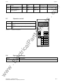
When supplied, the converter is controlled and parameterized by the parameterizing unit (PMU) located on the
front side of the converter.
Displays:
an
Converter statuses
faults, alarms
parameter numbers
index numbers
parameter values
ar
tM
Switch-on
Switch-off
P
Parameters
Indices
Parameter values
lP
Fault aknowledgement and
changeover between:
Parameter number
Parameter index
Parameter value
Raise/lower to
adjust the setpoint
(after select. of r000)
and selection of:
ca
A detailed description of the displays as well as the parameterizing and operator control possibilities of the
converter via the PMU, is provided in Section 6 "operator control".
lec
tri
The converter is supplied with the “factory setting“ (refer to Section 5 “Parameter list“) and access stage 2
(standard mode). After the drive converter has been owered-up for the first time, it goes into status 005 “drive
settings“ (P052 = 005). This status can be exited after entering valid motor data (refer to Sections 4.2.2 and
4.2.3) (P052 = 000) and the drive can then be powered-up
Parameterization is realize according to Section
4.2.2
as „Expert application“ when using motors from other manufacturers, sophisticated applications
(e.g.: Close-loop control, data set changeover, interface operation, etc.) or if hardware options are
available.
ww
w
.E
or 4.2.3
as “Standard application with V/f characteristic without hardware options“ for simple
applications with1 FT6 motors.
Siemens AG 6SE7087-6AD30
SIMOVERT Master Drives Operating Instructions
4-3
Start-up
01.95
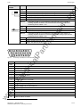
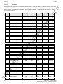
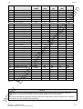
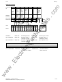
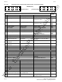
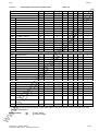
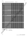
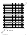
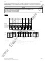
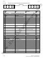
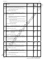
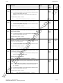
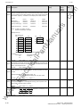
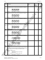
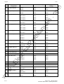
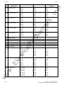
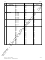
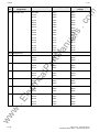
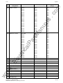
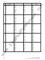
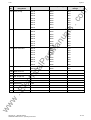
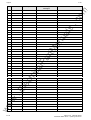
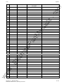
4.2.1.1
Motor list
[RPM]
.E
ww
4-4
[Nm]
0.8
1.4
2.2
1.7
4.3
3.0
3.7
3.5
2.9
2.1
5.2
4.6
3.6
2.1
9.0
7.0
4.8
2.1
7.5
6.9
5.8
4.6
11.4
10.3
8.5
5.5
16.9
14.7
10.1
4.0
23.5
22
20
17
23
18.5
12.0
33
31
27
22
24.5
23
Current In
lP
ca
Output Pn
[A]
1.2
2.1
1.7
2.4
2.9
4.1
1.9
2.6
3.4
3.1
2.6
3.4
3.9
3.2
3.8
4.9
5.5
3.5
4.1
5.6
7.3
7.7
6.6
8.7
11
9.1
8.3
11
12
5.8
12.5
17
24.5
25.5
10.9
13
12.6
17.5
24.5
31.5
29
8.4
11.0
ar
tM
6000
6000
3000
6000
3000
6000
2000
3000
4500
6000
2000
3000
4500
6000
2000
3000
4500
6000
2000
3000
4500
6000
2000
3000
4500
6000
2000
3000
4500
6000
2000
3000
4500
6000
2000
3000
4500
2000
3000
4500
6000
1500
2000
lec
tri
1FT6031-4AK7_
1FT6034-4AK7_
1FT6041-4AF7_
1FT6041-4AK7_
1FT6044-4AF7_
1FT6044-4AK7_
1FT6061-6AC7_
1FT6061-6AF7_
1FT6061-6AH7_
1FT6061-6AK7_
1FT6062-6AC7_
1FT6062-6AF7_
1FT6062-6AH7_
1FT6062-6AK7_
1FT6064-6AC7_
1FT6064-6AF7_
1FT6064-6AH7_
1FT6064-6AK7_
1FT6081-8AC7_
1FT6081-8AF7_
1FT6081-8AH7_
1FT6081-8AK7_
1FT6082-8AC7_
1FT6082-8AF7_
1FT6082-8AH7_
1FT6082-8AK7_
1FT6084-8AC7_
1FT6084-8AF7_
1FT6084-8AH7_
1FT6084-8AK7_
1FT6084-8SC7_
1FT6084-8SF7_
1FT6084-8SH7_
1FT6084-8SK7_
1FT6086-8AC7_
1FT6086-8AF7_
1FT6086-8AH7_
1FT6086-8SC7_
1FT6086-8SF7_
1FT6086-8SH7_
1FT6086-8SK7_
1FT6102-8AB7_
1FT6102-8AC7_
w
1
2
3
4
5
6
7
8
9
10
11
12
13
14
15
16
17
18
19
20
21
22
23
24
25
26
27
28
29
30
31
32
33
34
35
36
37
38
39
40
41
42
43
Torque Mn
Cooling
.c
Speed nn
[kW]
0.47
0.88
0.68
1.1
1.3
1.9
0.77
1.1
1.4
1.3
1.1
1.4
1.7
1.3
1.7
2.2
2.3
1.3
1.6
2.2
2.7
2.9
2.4
3.2
4.0
3.5
3.5
4.6
4.8
2.5
4.9
6.9
9.4
10.7
4.8
5.8
5.6
6.9
9.7
12.7
13.8
3.9
4.8
Self
Self
Self
Self
Self
Self
Self
Self
Self
Self
Self
Self
Self
Self
Self
Self
Self
Self
Self
Self
Self
Self
Self
Self
Self
Self
Self
Self
Self
Self
External
External
External
External
Self
Self
Self
External
External
External
External
Self
Self
ua
ls
Motor MLFB
an
PWE
om
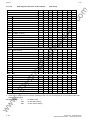
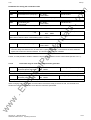
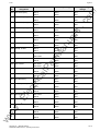
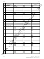
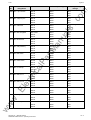
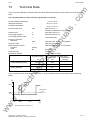
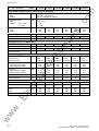
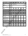
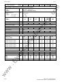
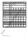
Settings for motor type P100. The tabulated data for torque, current and output, are nominal values and are valid
for a 3-ph. 380 V AC to 460 V AC converter supply voltage. Other motor data (e.g. also data for 3-ph.
208 V to 230 V AC supplies) are provided in the Engineering Manual „1FT6 three-phase servomotors“, Section
2.3.3 (motor overview).
Siemens AG 6SE7087-6AD30
SIMOVERT Master Drives Operating Instructions
01.95
Torque Mn
19.5
12.0
42
38
31
57
55
49
61
55
83
80
62
55
36
100
98
90
75
65
130
125
110
88
74
160
150
1.4
4.3
3.5
4.6
7.0
10.3
14.7
18.5
23
38
13.2
12
14.5
17.6
22.5
21.5
28
35
20.5
24.5
31
39
19
23
23
36
46
62
24
27
45
57
72
27
30
55
72
2.1
2.9
2.6
3.4
4.9
8.7
11
13
11.0
17.6
lP
ar
tM
3000
4500
1500
2000
3000
1500
2000
3000
1500
2000
1500
2000
1500
2000
3000
1500
2000
3000
1500
2000
1500
2000
3000
1500
2000
1500
2000
6000
3000
3000
3000
3000
3000
3000
3000
2000
2000
lec
tri
ca
1FT6102-8AF7_
1FT6102-8AH7_
1FT6105-8AB7_
1FT6105-8AC7_
1FT6105-8AF7_
1FT6105-8SB7_
1FT6105-8SC7_
1FT6105-8SF7_
1FT6108-8AB7_
1FT6108-8AC7_
1FT6108-8SB7_
1FT6108-8SC7_
1FT6132-6AB7_
1FT6132-6AC7_
1FT6132-6AF7_
1FT6132-6SB7_
1FT6132-6SC7_
1FT6132-6SF7_
1FT6134-6AB7_
1FT6134-6AC7_
1FT6134-6SB7_
1FT6134-6SC7_
1FT6134-6SF7_
1FT6136-6AB7_
1FT6136-6AC7_
1FT6136-6SB7_
1FT6136-6SC7_
1FT6034-1AK71-3A.0
1FT6044-1AF71-3A.0
1FT6061-1AF71-3A.0
1FT6062-1AF71-3A.0
1FT6064-1AF71-3A.0
1FT6082-1AF71-1A.0
1FT6084-1AF71-1A.0
1FT6086-1AF71-1A.0
1FT6102-1AC71-1A.0
1FT6105-1AC71-1A.0
Output Pn
[A]
[kW]
6.1
5.6
6.6
7.9
9.7
9
11.5
15.4
9.6
11.5
13
16.7
9.7
11.5
11.3
15.2
20.5
28.3
11.8
13.6
20.4
26.2
34.5
13.8
15.5
25
31.4
0.88
1.3
1.1
1.4
2.2
3.2
4.6
5.8
4.8
7.9
Cooling
Self
Self
Self
Self
Self
External
External
External
Self
Self
External
External
Self
Self
Self
External
Self
External
Self
Self
External
External
External
Self
Self
External
External
Self
Self
Self
Self
Self
Self
Self
Self
Self
Self
.E
44
45
46
47
48
49
50
51
52
53
54
55
56
57
58
59
60
61
62
63
64
65
66
67
68
69
70
71
72
73
74
75
76
77
78
79
80
Current In
[Nm]
an
[RPM]
om
Speed nn
.c
Motor MLFB
ua
ls
PWE
Start-up
Motor list
w
Table 4.1
NOTE
ww
It is possible to jump into the appropriate sequence step if incorrect entries have been made, taking into
account the access stage (P051) and a function selection (P052) which may be required.
It is recommended that the following parameters and function steps after the jump-in position are re-checked
and executed due to the background calculations !
Siemens AG 6SE7087-6AD30
SIMOVERT Master Drives Operating Instructions
4-5
Start-up
01.95
4.2.2
Parameterization "Standard application with V/f characteristic without hardware options"
Language:
0 = German, 1 = English, 2 = Espanol, 3 = Francais, 4 = Italiano
P051 = 2
Access “stage standard mode“
P052 = 5
Function selection "drive setting"
P071 =
Converter supply voltage [V]
P100.i001 =
Selecting a 1FT6 Siemens motor from the motor list, refer to Section
4.2.1.1
P208.x =
Define the encoder (refer to Section 5, Parameter list):
0: No encoder (not permissible)
1: ERN1387 encoder or compatible
2: Resolver with the motor pole pair number
3: Resolver with pole pair number 1
P420 =
Rated system speed [RPM]
Rated motor speed in the Appendix
P452.i001 =
Maximum speed, clockwise phase sequence [RPM]
P453.i001 =
Maximum speed, counter-clockwise phase sequence [RPM]
P462.i001 =
Ramp-up time [s] from standstill up to the rated system freq. (P420)
P464.i001 =
Ramp-down. time [s] from the rated system freq. (P420) down to
standstill
P052 = 0
If fault Ffxx occurs, refer to Section 7 „Fault finding“
.c
ua
ls
an
ar
tM
The converter executes a motor identification run after the first power-up
(refer to P330.x).
ww
w
.E
lec
tri
Ready
lP
P
ca
depress
om
P050 =
4-6
Siemens AG 6SE7087-6AD30
SIMOVERT Master Drives Operating Instructions
01.95
Start-up
Parameterization "expert application"
Language:
0: Deutsch, 1: English, 2: Espanol, 3: Francais, 4: Italiano
P051 = 3
Access stage "expert mode"
yes
P052 = 4
Function selection "hardware configuration“
P090 =
P091 =
Other parameters depending on the
option
ua
ls
no
Possible option boards: SCB, CB, TB
Define and parameterize the option boards:
refer to the Instruction Manuals for the option boards
Option boards:
0: none
1: CB
2: TB
3: SCB
an
Optionsboards?
.c
P050 =
Function selection "drive setting"
If fault "Fxxx", refer to Section 7 " Troubleshooting "
P071 =
Converter supply voltage [V]
250
Motor type: 0:
1 to 249:
250:
No motor
1FT6 Siemens motor according to the motor list
Motor from another manufacturer
Rated motor current [A]
P108.x =
Rated motor speed [RPM]
P109.x =
Motor pole pair number
Motor torque constant kT [Nm/A]
lec
tri
P110.x =
lP
P102.x =
ca
1 to 249
ar
tM
P052 = 5
P100.x =
om
4.2.3
Maximum permissible deviation of torque constant kT from the set value
(P110.x) [Nm/A]
P112.x =
Speed limit, from where the torque constant is adapted [%]
P113.x =
Rated motor torque [Nm]
ww
w
.E
P111.x =
P208.x =
P173.x =
Maximum motor current [A]
P186.x =
Speed-dependent torque constant [%]
P187.x =
Temperature-dependent torque constant [%]
Define encoder (refer to Section 5, parameter list):
0: No encoder (not permissible)
1: ERN1387 encoder or compatible
2: Resolver with the motor pole pair number
3: Resolver with pole pair number 1
Siemens AG 6SE7087-6AD30
SIMOVERT Master Drives Operating Instructions
4-7
Start-up
01.95
Only for P208.x =1: encoder pulse number (only powers of 2 permissible)
P211.x =
Only for P208.x = 2.3: Resolver field:
0:
Automatic adaption
1 to 7: Manual adaption
P213.x =
Only for P208.x =2.3: Resolver offset source:
0: Measured values
1: Value corresponding to the entry in P212.x
2: Transfer the measured value into P212.x
.c
om
P209.x =
Starting time [s]:
Accelerating time from standstill up to the rated speed with the rated
motor torque (P113.x)
P272.x =
Motor stator resistance [W]
ua
ls
P242.x =
an
Select motor identification:
0: Only after entering new motor data
1: After every ON command
P330 =
Voltage amplitude for motor identification [V]
P332.x =
Number of measuring cycles for motor identification
ar
tM
P331.x =
Select ground-fault test:
0: No ground-fault test
1: Only after the next ON command
2: After each ON command
P355 =
Test duration for the ground-fault test in phases U and W [ms]
P356 =
Test duration for the ground-fault test in phase V [ms]
ca
lP
P354 =
Current limit for the ground-fault test [A]
P357 =
Rated system speed [RPM]
Rated motor speed in the system
lec
tri
P420 =
Maximum speed, clockwise phase sequence [RPM]
P453.x =
Maximum speed, counter-clockwise phase sequence [RPM]
P462.x =
Accelerating time [s] from standstill up to the rated system speed (P420)
.E
P452.x =
Deceleration time [s] from the rated system speed (P420) down to
standstill
P485.x =
Rated system torque referred to the rated motor torque (P113.x) [%]
ww
w
P464.x =
P761.x =
P052 = 0
depress P key
4-8
Pulse frequency [kHz]
If fault "Fxxx", refer to Section 7 „Troubleshooting“. The converter
executes a motor identification run after the first power-up (refer to
P330.x).
Siemens AG 6SE7087-6AD30
SIMOVERT Master Drives Operating Instructions
Start-up
Connect
process data
Change factory setting for:
Command- and setpoint sources,
Destinations for signals and actual values
Process data: refer to Section 4.3.1
• Control word (commands)/status word (messages)
• Setpoint/actual values
ua
ls
no
yes
.c
Change process data connection?
om
01.95
Possible process data sources/destinations: (refer to Sections 4.3.2
to 4.3.6)
• Binary inputs, binary outputs
• Analog inputs, analog outputs
• Serial interface in the basic converter (SST1)
• Option boards (SCB, TSY, CB, TB)
Functions
required?
(software)
Define and parameterize power section options:
• Main contactor, output contactor (refer to Section 9 „options")
• Braking unit (refer to the Instruction Manual for the option)
Possible functions:
• Motor identification, first run,
• Restart-on-the-fly,
• Ground-fault test
Parameterize
functions
Parameterize function:
Section 4.3.10 "Functions"
and Section 5 „Parameter list"
lec
tri
no
yes
ar
tM
Par. dep. on
options
Possible options, power section:
• Main contactor,
• Output contactor,
• Braking unit
ca
no
yes
lP
Power
section options?
an
Simple applications: Refer to Section 4.2.6
ww
w
.E
Ready
Siemens AG 6SE7087-6AD30
SIMOVERT Master Drives Operating Instructions
4-9
Start-up
01.95
Rated systemmax. speed
Ramp-function
generator
P433, P438,
P443
P420, P452,
P453
P208, P209, P211
Closed-loop control
Closed-loop speed control P163 = 4
Source, torque
setpoint
Torque limiting
Adaption,
torque
constant
to the
gating
unit
ar
tM
Fig. 4.1
current
setpoints
decoupling,
current
control
P242
P462, P464
Setpoint channel
Calc.
.c
Source, speed
actual value
Speed
controller
ua
ls
Source, speed
setpoint
om
Simplified block diagrams for setpoint channel and closed-loop control
an
4.2.4
Source, encoder
P499, P493
lP
Calc.
P486
ca
P208, P209, P211
Setpoint channel
Fig. 4.2
to
gating
unit
lec
tri
Adaption
torque
constant
current
setpoint
values
de-couple
curr.
control
Closed-loop control
Closed-loop torque control P163 = 5
refer to section 5 “Parameter list“
♦ detailed function diagrams:
refer to section 4.9 “Function Diagrams“
ww
w
.E
♦ detailed parameter description:
4-10
Siemens AG 6SE7087-6AD30
SIMOVERT Master Drives Operating Instructions
01.95
Start-up
4.2.5
Simple application examples for connecting process data with connection assignment
om
Connecting-up: Refer to Section 3.3 "Control terminal strip"
Factory setting:
PMU
BA2
BA2
BA2
P24
BE1
BE2
BE3
BE4
BE5
Floating contact
Fault
P603.1 = 1002
P554.2 = 1001
ON/OFF1
P555.2 = 1002
OFF2 (pulse inhibit)
P565.2 = 1003
Acknowledge
P580.2 = 1004
Fixed setpoint 0/1
Basic /reserve
P590 = 1005
(activates above commands)
Speed/frequency
actual value
P655.1 = 0219
P554.1 = 1010
P573.1 = 1010
P574.1 = 1010
Speed setpoint
via mot.pot.
P443.1 = 1002
Speed setpoint
via fixed setpoint: P443.2 = 1001
an
-X102/33 AA1M
-X102/34 AA1
ON/OFF1
Mot.pot. raise
Mot.pot. lower
ar
tM
-X100/06
-X100/07
-X100/08
-X101/13
-X101/16
-X101/17
-X101/18
-X101/19
-X101/20
ua
ls
CU3
.c
Switch-on/off as well as setpoint input via the PMU, messages and actual values via the terminal strip.
Terminal strip only operational if binary input 5 (BE5) is energized (high signal level corresponds to "reserve").
Manual/automatic operation:
Setpoint and command input from the automation unit via serial interface
(SST1), OFF3 and monitoring external faults, also possible via terminal
strip.
Manual operation (BE5 low level):
Setpoint- and command input via terminal strip.
SST2
BA2
BA2
BA2
P24
BE1
BE2
BE3
BE4
BE5
Floating contact
Operation
lec
tri
-X100/06
-X100/07
-X100/08
-X101/13
-X101/16
-X101/17
-X101/18
-X101/19
-X101/20
ca
CU3
lP
Automatic operation (BE5 high level):
Automation
unit
ON/OFF1
OFF3
Acknowledge
cw phase seq.
ccw phase seq.
P554.2 = 2001
P559.2 = 2001
P565.2 = 2001
P571.2 = 2001
P572.2 = 2001
Speed setpoint
P443.2 = 2002
P554.1 = 1001
P558.1 = 1002 P558.2 = 1002 (always active)
P565.1 = 1003
P575.1 = 1004 P575.2 = 1004 (always active)
P590 = 1005
-X102/27 AE1
-X102/28 AE1M
Speed setpoint
0 - 10 V
P443.1 = 1003
-X102/33 AA1M
-X102/34 AA1
Output current
P655 = 0004
.E
ON/OFF1
OFF3 (fast stop)
Acknowledge
Fault, external 1
Basic /reserve
If a terminal cannot be connected-up as source or destination, it should be checked as to whether it has
already been used for other signals.
ww
w
Tip:
P602.1 = 1002
SST
Siemens AG 6SE7087-6AD30
SIMOVERT Master Drives Operating Instructions
4-11
Start-up
01.95
Start-up aids
4.3.1
Process data
om
4.3
Control word (control word 1 and control word 2)
4.3.1.1.1
Introduction and application example
ua
ls
4.3.1.1
.c
Process data are commands and setpoints which are entered into the converter from "outside" as well as signals
and actual values which the converter outputs.
The two control words 1 (bits 0 to 15) and 2 (bits 16 to 31) output commands and external signals (messages) to
the converter. Their status can be read-out via parameter r550 or r967 (control 1) and r551 (control word 2).
An overview is provided in Section 4.3.1.1.2 "Overview of the control word".
The significance of the possible commands and signals, entered externally, is described in Section 4.3.1.1.4
"Significance of the control word commands".
an
Every control word bit is assigned a selection parameter, which defines from which source(s) this bit can be
changed (refer to Section 4.3.1.1.2, righthand column).
Index
i001 Basic setting
i002 Reserve setting
ar
tM
The selection parameters for the sources are, with the exception of P590 (source selection for control word bit 30
"basic/reserve setting") and P591 (source selection for control word bit 31 "HS checkback signal") are indexed 2x
as follows:
An overview of the possible sources, which are assigned fixed values (0-6004 non-consecutive), is provided in
Section 4.3.1.1.3 "Selecting the control word source".
lP
Values 0 and 1 are an exception in this overview; here, no sources are selected, but the bits are permanently set
to 0 (LOW) or 1 (HIGH) (also refer to select parameters P554 to P591 in Section 5 "Parameter list").
ca
If a value, which is assigned a terminal (binary input BI) (1001 to 1007, 4101 to 4116, 4201 to 4216, 5001), is
assigned once in a select parameter for the source, then it is no longer available in the same index of another
select parameter, as a terminal is only suitable for entering a control word bit.
NOTES
lec
tri
The control word commands "OFF2" (bit1), "OFF3" (bit2) and "acknowledge" (bit7) are always simultaneously
effective from 3 sources (can be parameterized) !
"Acknowledge" (bit7) is also always effective from the PMU !
If the "on" command (bit 0) is connected to a serial interface (SST1, CB/TB, SCB-SST), then the following must
be observed for safety-related reasons:
ww
w
.E
Additionally, an "OFF2" or "OFF3" command must be parameterized at the terminal strip/PMU, as otherwise
the converter cannot be shutdown with a a defined command, when communications fail!
4-12
Siemens AG 6SE7087-6AD30
SIMOVERT Master Drives Operating Instructions
01.95
Start-up
...
31
.
.
1: Inv. enable
0: Inv. inhibit
:
P558
P559
P560
P555
P556
P557
...
1: M. c. chkbk.
0: No m. c.
chkbk,
3
P561
P...
P...
Basic setting i001=
i001=
i001=
i001=
i001=
i001=
Reserve sett. i002=
i002=
i002=
i002=
i002=
i002=
.c
Selection
parameter
2
P591
ua
ls
P554
1
1: Op. cond..
0: OFF3
1: ON
0: OFF1
0
1:. Op. cond.
0: OFF2
Control word
bit
om
Application example:
1007 1010 2001 2004 6001 6004
...
3001 bis 5001
an
...
ar
tM
SST1
(word1)
SST1
(word4)
SST2
(word1)
SST2
(word4)
Source
0000 0001 1001 1002 1003
CU,BE7
-X101:22
PMU
Value
Constant
value = 0
Constant
value = 1
CU,Be1
-X101:16
CU,BE2
-X101:17
CU,BE3
-X101:18
Changeover via
contr. word bit 30
P590
Options
Basic set.:
via PMU (keys I/0)
Reserve set.:
via bin. input 1 of CU
Op. cond/OFF2:
Basic set.:
Constant value= 1
= always op. cond.
Reserve set.:
Constant value = 1
= always op. cond.
Op. cond./OFF3:
Basic set.:
Constant value= 1
= always op. cond.
Reserve set.:
via bi. input 2 of CU
lP
ON/OFF1:
ca
NOTE
For OFF2 and OFF3, 3 selection parameters can be assigned differently in the same index!
Basic set.:
Constant value = 1
= always inv. enable.
Reserve set.:
via serial interface
SST1 of the CU
ww
w
.E
lec
tri
Inv. enable/inhibit:
Siemens AG 6SE7087-6AD30
SIMOVERT Master Drives Operating Instructions
4-13
Start-up
01.95
12
6
3
4
1
0
2
„Control word 1"
31
PMU-Display
8
10
5
7
9
11
13
14
„Control word 1"
27
29
28
30
„Control word 2"
21
23
(visualization parameter r550 oder r967)
20
Low
Comments
0
1
ON
Operating condition
OFF1 (stop)
OFF2 (electrical)
(Priority OFF 2/3/1)
3 sources simultaneously effective;
(Priority OFF 2/3/1)
2
Operating condition
OFF3 (fast stop)
3 sources simultaneously effective;
(Priority OFF 2/3/1)
3
4
5
6
7
Inverter enable
RFG enable
Start RFG
Setpoint enable
Acknowledge
Inhibit inverter
HInhibit RFG
RFG stop
Inhibit setpoint
Inverter enable
Ramp-function gen. enable
Hold ramp-function generator
8
9
10
Inching 1 ON
Inching 2 ON
Control from the PLC
Inching 1 OFF
Inching 2 OFF
No control
lP
ca
lec
tri
.E
w
ww
4-14
an
ar
tM
Simultaneously effective from 3
sources and PMU;
Positive edge evaluation
Clockwise phase
sequence
12 Counter-clockwise phase
sequence
13 Mot. potentiometer, raise
14 Mot. potentiometer, lower
15 No fault, external 1
Fault, external 1
„Control word 2"
(visualization parameter r551)
16
SDS bit 0 (LSB)
17 SDS bit 1 (MSB)
18 MDS bit 0 (LSB)
19
20 FSW bit 0 (LSB)
21 FSW bit 1 (MSB)
22
23 Enable restart-on-the-fly
Restart-on-the-fly inhibited
24
25 Controller enable
Controller inhibited
26 No fault, external 2
Fault, external 2
27 slave drive
master drive
28 No alarm, external 1
Alarm, external 1
29 No alarm, external 2
Alarm, external 2
30 Reserve setting for
Basic setting for setpoints
setpoints and control word and control word
31 HS checkback signal
No HS checkback signal
17
16
18
ua
ls
Bit High
11
24
26
19
22
25
om
15
Overview of the control word (control word 1 and control word 2)
.c
4.3.1.1.2
Source
selection
P554
P555
P556
P557
P558
P559
P560
P561
P562
P563
P564
P565
P566
P567
P568
P569
Only effective via CB, TB, SST1,
SST/SCB
Logic op. with bit 12
P571
Logic op. with bit 11
P572
Logic op. with bit 14
Logic op. with bit 13
P573
P574
P575
Setpoint channel data set
Logic op. with bit 16
Motor data set
Reserved
Logic operation with bit 21
Logic operation with bit 20
Reserved
P576
P577
P578
P580
P581
P583
Reserved
P585
P586
P587
P588
P589
P590
Can only connected at the converter P591
term.strip or SCB
Siemens AG 6SE7087-6AD30
SIMOVERT Master Drives Operating Instructions
01.95
Start-up
2
3
4
5
558 to 560.1
561.1
562.1
563.1
558 to 560.2
561.2
562.2
563.2
7
564.1
565 to 567.1
564.2
565 to 567.2
x
x
x
x
xG/R
xG/R xG/R xG/R xG/R
x
x
x
x
x
x
x
x
x
x
x
x
x
x
xR for 565
x
x
x
x
x
x
x
x
x
x
x
x
x
x
x
x
x
x
x
x
always
x
x
x
x
x
.c
xG/R
x
x
x
x
x
x
x
x
x
6
ua
ls
Bit
0
1
Selection P. basic setting 554.1 555 to 557.1
Selection P. reserve setting 554.2 555 to 557.2
Value Source
0000 Constant value = 0
x
0001 Constant value = 1
xG/R
1001 CU, BE1, -X101:16
xR
x
1002 CU, BE2, -X101:17
x
xR for 555
1003 CU, BE3, -X101:18
x
x
1004 CU, BE4, -X101:19
x
x
1005 CU, BE5, -X101:20
x
x
1006 CU, BE6, -X101:21
x
x
1007 CU, BE7, -X101:22
x
x
1010 PMU
xG
x
2001 SST1,PMU -X300 (word1)
x
x
2004 SST1,PMU -X300 (word4)
6001 SST2,-X100:1...5 (word1)
x
x
6004 SST2,-X100:1...5 (word4)
(bits 0-7)
om
Selecting the source for control word 1
an
4.3.1.1.3
x
x
x
x
x
x
x
x
x
x
x
x
x
x
x
x
x
x
x
x
x
x
x
x
x
x
4504
w
5001
x
x
x
x
x
x
x
x
x
x
x
x
x
x
x
x
x
x
x
x
x
x
x
x
x
x
x
x
x
x
x
x
x
x
x
x
x
x
x
x
x
x
x
x
x
x
x
x
x
x
x
x
x
x
x
x
x
x
x
x
x
x
x
x
x
x
x
x
x
x
x
x
x
x
x
x
x
x
x
x
x
x
x
x
x
x
x
x
x
x
x
x
x
x
x
x
x
x
x
x
x
x
x
x
x
x
x
x
x
x
x
x
x
x
x
lP
x
x
x
x
x
x
x
x
x
x
x
x
x
x
x
x
x
lec
tri
ca
CB/TB (word1)
CB/TB (word4)
SCI 1and2,slave1,BE1
BE2
Consecutively to
BE10
only SCI 2,slave 1,BE11
BE12
Consecutively to
BE16
SCI 1and2,slave2,BE1
BE2
Consecutively to
BE10
only SCI 2,slave 2,BE11
BE12
Consecutively to
BE16
SCB-SST (USS /peer-t-peer)
(word1)
SCB-SST (USS /peer-t-peer)
(word4)
TSY,BE
.E
3001
3004
4101
4102
...
4110
4111
4112
...
4116
4201
4202
...
4210
4211
4212
...
4216
4501
ar
tM
OPTIONS
x
x: Value can be assigned for the selection parameters (BE can only be assigned once in the same index of all
selection parameters!)
ww
Factory setting:
xG:
xR:
for basic setting
for reserve setting
Siemens AG 6SE7087-6AD30
SIMOVERT Master Drives Operating Instructions
4-15
Start-up
01.95
Source
Constant value = 0
Constant value = 1
CU, BE1, -X101:16
CU, BE2, -X101:17
CU, BE3, -X101:18
CU, BE4, -X101:19
CU, BE5, -X101:20
CU, BE6, -X101:21
CU, BE7, -X101:22
PMU
SST1,PMU -X300 (word1)
SST1,PMU -X300 (word4)
SST2,-X100:1...5 (word1)
SST2,-X100:1...5 (word4)
11
12
13
14
569.1
571.1
572.1
573.1
574.1
569.2
571.2
572.2
573.2
574.2
xR
xR
xG/R xG/R
x
x
x
x
x
x
x
x
x
x
x
x
x
x
x
x
x
x
575.1
575.2
xG/R
x
x
x
x
x
x
x
x
x
x
x
x
x
x
x
xG
x
x
x
x
x
x
x
x
x
x
x
x
x
x
x
x
x
x
x
x
x
x
x
x
x
x
x
x
x
x
x
x
x
x
x
x
x
x
x
x
x
x
x
x
x
x
x
x
x
x
x
x
x
x
x
x
x
x
x
x
x
x
x
x
x
x
x
x
x
x
x
x
x
x
x
x
x
x
x
x
x
x
x
x
x
x
x
x
x
x
x
x
x
x
x
x
x
x
x
x
x
x
x
x
x
x
x
x
x
x
x
x
x
x
x
x
x
x
x
x
x
x
x
x
x
x
x
x
x
x
x
x
x
x
x
x
x
x
x
ca
lec
tri
x
x
x
x
x
x
x
xG
x
15
x
lP
CB/TB (word1)
CB/TB (word4)
SCI 1and2,slave1,BE1
BE2
Consecutively to
BE10
only SCI 2,slave 1,BE11
BE12
Consecutively to
BE16
SCI 1and2,slave2,BE1
BE2
Consecutively to
BE10
only SCI 2,slave 2,BE11
BE12
Consecutively to
BE16
SCB-SST (USS /peer-t-peer) (word1)
SCB-SST (USS /peer-t-peer) (word4)
TSY,BE
.E
3001
3004
4101
4102
...
4110
4111
4112
...
4116
4201
4202
...
4210
4211
4212
...
4216
4501
4504
5001
x
x
xG/R xG/R
x
x
x
x
x
x
x
x
x
x
x
x
x
x
x
x
x
x
ar
tM
OPTIONS
10
.c
Value
0000
0001
1001
1002
1003
1004
1005
1006
1007
1010
2001
2004
6001
6004
9
ua
ls
Bit
8
Selection P. basic setting 568.1
Selection P. reserve setting 568.2
(bits 8-15)
om
Selecting the source for control word 1
an
4.3.1.1.4
w
x: Value can be assigned for the selection parameters (BE can only be assigned once in the same index of all
selection parameters!)
xG:
xR:
for basic setting
for reserve setting
ww
Factory setting:
4-16
Siemens AG 6SE7087-6AD30
SIMOVERT Master Drives Operating Instructions
01.95
Start-up
Source
Constant value = 0
Constant value = 1
CU, BE1, -X101:16
CU, BE2, -X101:17
CU, BE3, -X101:18
CU, BE4, -X101:19
CU, BE5, -X101:20
CU, BE6, -X101:21
CU, BE7, -X101:22
PMU
SST1,PMU -X300 (word1)
SST1,PMU -X300 (word4)
SST2,-X100:1...5 (word1)
SST2,-X100:1...5 (word4)
18
577.1
577.2
x
x
x
x
21
578.1
580.1
581.1
578.2
580.2
581.2
xG
x
x
x
x
xR
x
x
x
xG/R
x
x
x
x
x
x
x
x
583.1
583.2
xG/R
x
x
x
x
x
x
x
x
x
x
x
x
x
x
x
x
x
x
x
x
x
x
x
x
x
x
x
x
x
x
x
x
x
x
x
x
x
x
x
x
x
x
x
x
x
x
x
x
x
x
x
x
x
x
x
x
x
x
x
x
x
x
x
x
x
x
x
x
x
x
x
x
x
x
x
x
x
x
x
x
x
x
x
x
x
x
x
x
x
x
x
x
x
x
x
x
x
x
x
x
x
x
x
x
x
x
x
x
x
x
x
x
ca
lec
tri
.E
23
x
x
x
x
x
x
x
x
x
x
x
x
x
x
x
x
x
lP
CB/TB (word1)
CB/TB (word4)
SCI 1and2,slave1,BE1
BE2
Consecutively to
BE10
only SCI 2,slave 1,BE11
BE12
Consecutively to
BE16
SCI 1and2,slave2,BE1
BE2
Consecutively to
BE10
only SCI 2,slave 2,BE11
BE12
Consecutively to
BE16
SCB-SST (USS /peer-t-peer) (word1)
SCB-SST (USS /peer-t-peer) (word4)
TSY,BE
22
x
ar
tM
OPTIONS
3001
3004
4101
4102
...
4110
4111
4112
...
4116
4201
4202
...
4210
4211
4212
...
4216
4501
4504
5001
20
xG/R xG/R xG/R
x
x
x
x
x
x
x
x
x
x
x
x
x
x
x
x
x
x
x
x
x
x
x
x
19
om
Value
0000
0001
1001
1002
1003
1004
1005
1006
1007
1010
2001
2004
6001
6004
17
.c
Bit 16
Selection P. basic setting 576.1
Selection P. reserve setting 576.2
(Bit 16-23)
ua
ls
Selecting the source for control word 2
an
4.3.1.1.5
w
x: Value can be assigned for the selection parameters (BE can only be assigned once in the same index of all
selection parameters!)
xG:
xR:
for basic setting
for reserve setting
ww
Factory setting:
Siemens AG 6SE7087-6AD30
SIMOVERT Master Drives Operating Instructions
4-17
Start-up
01.95
Source
Constant value = 0
Constant value = 1
CU, BE1, -X101:16
CU, BE2, -X101:17
CU, BE3, -X101:18
CU, BE4, -X101:19
CU, BE5, -X101:20
CU, BE6, -X101:21
CU, BE7, -X101:22
PMU
SST1,PMU -X300 (word1)
SST1,PMU -X300 (word4)
SST2,-X100:1...5 (word1)
SST2,-X100:1...5 (word4)
25
26
27
28
29
30
585.1
586.1
587.1
588.1
589.1
590
585.2
586.2
587.2
588.2
589.2
590
x
xG/R
xG/R xG/R
x
xG/R xG/R
x
x
x
x
x
x
x
x
x
x
x
x
x
x
x
x
x
x
x
x
x
x
x
x
x
x
x
x
x
x
x
x
x
x
x
x
x
591
591
x
x
x
x
x
x
x
x
x
x
x
x
x
x
x
x
x
x
x
x
x
x
x
x
x
x
x
x
x
x
x
x
x
x
x
x
x
x
x
x
x
x
x
x
x
x
x
x
x
x
x
x
x
x
x
x
x
x
x
x
x
x
x
x
x
x
x
x
x
x
x
x
x
x
x
x
x
x
x
x
x
x
x
x
x
x
x
x
x
x
x
x
x
x
x
x
x
x
x
x
x
x
x
x
x
x
x
x
x
x
x
x
x
x
x
x
x
x
x
x
x
x
x
x
x
x
x
x
x
x
x
x
x
x
x
x
x
x
x
x
x
x
x
x
x
x
x
x
.E
lec
tri
ca
lP
CB/TB (word1)
CB/TB (word4)
SCI 1and2,slave1,BE1
BE2
Consecutively to
BE10
only SCI 2,slave 1,BE11
BE12
Consecutively to
BE16
SCI 1and2,slave2,BE1
BE2
Consecutively to
BE10
only SCI 2,slave 2,BE11
BE12
Consecutively to
BE16
SCB-SST (USS /peer-t-peer) (word1)
SCB-SST (USS /peer-t-peer) (word4)
TSY,BE
x
ar
tM
OPTIONS
3001
3004
4101
4102
...
4110
4111
4112
...
4116
4201
4202
...
4210
4211
4212
...
4216
4501
4504
5001
x
x
x
x
x
x
x
x
x
31
ua
ls
Value
0000
0001
1001
1002
1003
1004
1005
1006
1007
1010
2001
2004
6001
6004
24
.c
Bit
Selection P. basic setting
Selection P. reserve setting
(bits 24-31)
om
Selecting the source for control word 2
an
4.3.1.1.6
w
x: Value can be assigned for the selection parameters (BE can only be assigned once in the same index of all
selection parameters)
ww
Factory setting:
4-18
x:
xG:
xR:
for P590 / P591
for the basic setting
for the reserve setting
Siemens AG 6SE7087-6AD30
SIMOVERT Master Drives Operating Instructions
01.95
4.3.1.1.7
Start-up
Significance of control word- (1 and 2) commands
om
The converters statuses can be read in the operating display r000: e.g. READY-TO-SWITCH-ON r000=009
The function sequences are described in the sequence in which they are realized.
Bit 0: ON command (↑ "ON")
After the command has been accepted:
ua
ls
♦ Changeover into the status PRE-CHARGING (010)
Main contactor/bypass contactor (option) are switched-in, if present
Pre-charging is realized
♦ Changevoer into the RUN status (011)
♦ Changeover into the RUN status (014)
After the command has been accepted.
an
Bit 0: OFF1 command (L "OFF1")
The OFF1 command (stop) is executed with an L signal.
.c
The command is executed with a positive edge change from L to H (L → H) only in the READY-TO-SWITCH-ON
(009).
♦ If one of the statuses
ar
tM
♦ Changeover into the status OFF 1 (015), if the inverter is in an enabled status.
The setpoint is inhibited at the ramp-function generator input (setpoint=0), so that the drive is decelerated
along the parameterized deceleration ramp (P464) down to the OFF shutdown frequency (P514).
After the OFF shutdown frequency has been reached, and the OFF delay time has expired (P516), the
inverter pulses are inhibited and the main contactor, if available, is opened (also refer to "ramp-function
generator" Section 4.3.7).
If the OFF 1 command is again removed during ramp-down (ON command), ramp-down is terminated and
the drive again goes into the RUN status (014).
lP
PRE-CHARGING
(010),
READY
(011),
is present, the inverter pulses are inhibited and the main contactor, if available, is opened.
ca
♦ Changeover into the status SWITCH-ON INHIBIT (008)
♦ If neither an OFF2 nor OFF3 command is present:
Then the READY-TO-SWITCH-ON status is entered (009)
ww
w
.E
lec
tri
♦ For the slave drive, the drive remains active, until a speed is reached, below the OFF shutdown speed P514,
as a result of a lower torque reference from the master drive.
Siemens AG 6SE7087-6AD30
SIMOVERT Master Drives Operating Instructions
4-19
Start-up
01.95
Bit 1: OFF2 command (L "OFF2")
After the command has been accepted:
♦ The inverter pulses are inhibited, and the main contactor/bypass contactor (option) is opened
.c
♦ Changeover into the SWITCH-ON INHIBIT status (008)
om
The OFF2 command (electrical) is realized with an L signal.
NOTE
The OFF2 command is simultaneously effective from three sources (P555, P556 and P557)!
ua
ls
Bit 2: OFF3 command (L "OFF3")
The OFF3 command (fast stop) is executed with the L signal.
After the command has been accepted:
♦ Changeover into the status OFF3 (016), if the drive is in a status with the inverter enabled
♦ If one of the statuses
ar
tM
an
• The setpoint at the RFG input is inhibited (setpoint = 0), so that the drive decelerates along the torque limit
down to the OFF shutdown speed (P514).
After the off shutdown speed has been reached and after the OFF delay time (P516) has expired, the
inverter pulses are inhibited, and the main/bypass contactor, if available, is opened. Deceleration is still
continued if the OFF3 command is withdrawn while the drive is decelerating.
(also refer to „ramp-function generator“, Section 4.3.7)
PRECHARGING
READY
(010),
(011),
is present:
The inverter pulses are inhibited, and the main contactor/bypass contactor, if available, is opened.
lP
♦ Changeover into the SWITCH-ON INHIBIT status (008)
NOTE
The OFF 3 command is simultaneously effective from three sources (P558, P559 and P560)!
ca
Priority of the OFF commands OFF2 > OFF3 > OFF1
Bit 3: Inverter enable command (H "inverter enable")
lec
tri
The INVERTER ENABLE command (inverter enable) is executed with an H signal.
After the command has been accepted:
♦ If the drive is in the READY status (011), the system changes into the RUN status (014), and the inverter
pulses are enabled.
Bit 3: INVERTER inhibit command (L "inverter inhibit").
.E
The INVERTER INHIBIT command (inverter inhibit) is executed with an (L signal)
After the command has been accepted:
♦ If the status
is available:
RUN
(014)
The drive goes into the RUN STATUS (011) and the inverter pulses are inhibited.
ww
w
♦ If the drive is in the OFF1 status (015/stop):
The inverter pulses are inhibited, the main contactor, if available, is opened, and the drive goes into the
SWITCH-ON inhibit status (008).
♦ If the status OFF3 (016 / fast stop) is available,
the command, inverter inhibit is ignored, and fast stop continues.
4-20
Siemens AG 6SE7087-6AD30
SIMOVERT Master Drives Operating Instructions
01.95
Start-up
Bit 4: Ramp-function generator inhibit command (L "inhibit ramp-function generator")
After the command has been accepted:
♦ The ramp-function generator output is set to setpoint = 0.
.c
Bit 5: Ramp-function generator stop command (L "ramp-function generator stop")
om
The RAMP-FUNCTION GENERATOR INHIBIT command (inhibit ramp-function generator) is executed for the
setpoint with an L signal, only in the RUN status (014).
The ramp-function generator stop command (hold ramp-function generator), is executed for the setpoint, with
an L signal, only in the RUN status (014).
♦ The actual setpoint is frozen at the ramp-function generator output.
Bit 6: Setpoint enable command ( H "setpoint enable")
The command is executed with an H signal.
After the command has been accepted:
Bit 7: Acknowledge command (↑ "Acknowledge")
an
♦ The setpoint at the ramp-function generator input is enabled.
ua
ls
After the command has been accepted:
After the command has been accepted:
ar
tM
The command is executed with a positive edge change from L to H (L → H) only in the FAULT status (007).
♦ All actual faults are deleted after having been previously transferred into the diagnostics memory
♦ If no faults are present:
The drive changes into the status SWITCH-ON INHIBIT (008)
lP
♦ If actual faults are present:
The drive remains in the FAULT status (007).
NOTE
ca
The acknowledge command is simultaneously effective from three sources (P565, P566 and P567) and
alwlays from the PMU!
lec
tri
Bit 8: Inching 1 ON command (↑ "Inching 1 ON")
The command is executed with a positive edge change from L to H (L → H) only in the READY-TO-SWITCH-ON
status (009).
After the command has been accepted
.E
♦ an ON command is automatically executed (description, refer to control word bit 0) and inching frequency 1
P448 is enabled in the setpoint channel.
The ON/OFF1 command (bit 0) is ignored for active inching operation.
Bit 8: Inching 1 OFF command (L "inching 1 OFF")
The command is executed with an L signal.
After the command has been accepted:
ww
w
♦ An OFF 1 command is automaticaly executed (description, refer to control word bit 0).
Siemens AG 6SE7087-6AD30
SIMOVERT Master Drives Operating Instructions
4-21
Start-up
01.95
Bit 9: Inching 2 ON command (↑ "inching 2 ON")
om
The command is executed with a positive edge change from L to H (L → H) only in the status READY-TOSWITCH-ON (009).
After the command has been accepted
.c
♦ an ON command (description, refer to control word bit 0) is automatically executed, and inching frequency 2
P449 is enabled in the setpoint channel.
The ON/OFF1 command (bit 0) is ignored for active inching.
Bit 9: Inching 2 OFF command (L "inching 2 OFF")
The command is executed with the L signal.
ua
ls
After the command has been accepted:
♦ an OFF1 command (description, refer to control word bit 0) is automatically executed.
Bit 10: Control from the PLC command (H "control from the PLC)
The command is executed with an H signal.
an
Process data PZD (control word, setpoints) which were sent via the SST1 interface of CU, the CB/TB interface
(option) and the SST/SCB interface (option), are only evaluated if the command was accepted.
♦ If several interfaces are operational, only the process data of the interfaces are evaluated, which transmit the
H signal.
ar
tM
♦ For an L signal, the last values are retained in the appropriate dual port RAM of the interface.
An H signal appears in the visualization parameter r550 "control word 1", if one of the interfaces transmits an H
signal!
Bit 11: Clockwise phase sequence command (H "clockwise phase sequence")
The command is executed with an H signal.
lP
After the command has been accepted, the setpoint is influenced depending on the assignment of bit 12
"counter-clockwise phase sequence".
ca
Refer to Section 4.4 "Function diagram, setpoint channel CU (Section 2)"!
Bit 12: Counter-clockwise phase sequence command (H "counter-clockwise phase sequence")
The command is executed with an H signal.
lec
tri
After the command has been accepted, the setpoint is influenced depending on the assignment of bit 11
"clockwise phase sequence".
Refer to Section 4.4 "Function diagram, setpoint channel CU (Section 2)"!
NOTE
.E
The counter-clockwise phases sequence- and clockwise phase sequence commands have no influence
on supplementary setpoint 2, which is added after the ramp-function generator!
Bit 13: Motorized potentiomenter, raise command (H "raise motorized potentiometer")
The command is executed with an H signal.
The motorized potentiometer in the setpoint channel is increased after the command has been accepted.
w
Refer to Section 4.4 "Function diagram, setpoint channel CU (Part 1)"!
ww
Bit 14: Motorized potentiometer, lower command (H "motorized potentiometer, lower")
The command is executed with an H signal.
After the command has been accepted, the motorized potentiometer is lowered in the setpoint channel.
Refer to section 4.4 „Function diagram, setpoint channel CU (Section 1)"!
4-22
Siemens AG 6SE7087-6AD30
SIMOVERT Master Drives Operating Instructions
01.95
Start-up
Bit 15: Fault, external 1 command (L "fault, external 1")
om
The command is executed with an L signal.
After the command has been accepted:
.c
The drive goes into the FAULT status (007) (fault F035)
The inverter pulses are inhibited and the main contactor, if available, is opened (also refer to Section 7
"Troubleshooting")
Bit 16: Setpoint channel data set SDS bit 0 command
In conjunction with bit 17 "SDS BIT 1" the command allows toggling between four possible setpoint channel data
sets.
ua
ls
Refer to Section 4.4 "Function diagram, setpoint channel CU (Part 1) / data sets“!
Bit 17: Setpoint channel data set SDS bit 1 command
In conjunction with bit 16 "SDS BIT 0" this command allows toggling between four possible setpoint channel data
sets.
Bit 18: Motor data set MDS bit 0 command
an
Refer to Section 4.4 "Function diagram, setpoint channel CU (Part 1) / data sets"!
ar
tM
The commands permits toggling between two motor data sets, and is only in the statuses
READY-TO-SWITCH-ON
(009)
PRE-CHARGING
(010)
READY
(011).
Refer to Section 4.4 "Function diagram, data sets"!
Bit 20: Fixed setpoint FSW bit 0 (LSB command):
lP
The command, in conjunction with bit 21 "FSW BIT 1" permits one of the four possible fixed setpoints to be
selected.
Refer to Section 4.4 "Function diagram, setpoint channel CU (Section 1) / data sets"!
ca
Bit 21: Fixed setpoint FSW bit 1 (MSB) command:
The command, in conjunction with bit 20 "FSW BIT 0" permits one of the four possible fixed setpoints to be
selected.
lec
tri
Refer to Section 4.4 "Function diagram, setpoint channel CU (Section 1) / data sets"!
Bit 23: Restart-on-the-fly enable command (H "enable restart-on-the-fly")
This command enables the restart-on-the-fly function.
Bit 25: Controller enable command (H „controller enable")
.E
The command enables the speed controller if the converter inverter pulses are enabled.
Refer to „control function diagrams“, Section 4.4 .
Bit 26: Fault, external 2 command (L "fault, external 2")
The command is identified with an L signal, and is only active after pre-charging has been completed from
READY status (011) onwards and an additional 200 ms delay.
After the command has been accepted
ww
w
♦ The drive goes into the FAULT status (007) (fault F036)
The inverter pulses are inhibited, the main contactor, if available, is opened (also refer to Section 7
"Troubleshooting").
Siemens AG 6SE7087-6AD30
SIMOVERT Master Drives Operating Instructions
4-23
Start-up
01.95
Bit 27: Master/slave drive command (H "slave drive"/L "master drive" )
om
The commands switches between speed control (master drive) and torque control (slave drive). For speed
controls, the speed setpoint is injected into the control via the setpoint channel as well as the supplementary
torque setpoint For torque control, the main torque setpoint is used as input quantity.
Bit 28: Alarm, external 1 command (L "alarm, external 1")
.c
The command is executed with an L signal.
After the command has been accepted
ua
ls
♦ The operating status is retained. An alarm message (A015) is output (also refer to Section 7
"Troubleshooting")
Bit 29: Alarm, external 2 command (L "alarm, external 2")
The command is executed with an L signal.
After the command has been accepted:
an
♦ The operating status is retained.
An alarm message (A016)is output (also refer to Section 7 "Troubleshooting").
Bit 30: Selection, basic/reserve setting command (L "basic setting / H "reserve setting")
The command activates the BASIC SETTING with an L signal and the RESERVE SETTING with an H signal.
ar
tM
After the command has been accepted:
♦ The parameter settings of the basic- or reserve setting for the control word itself, the setpoint channel, and
the closed-loop control are activated (refer to Section 4.4 "Function diagrams, data sets").
Bit 31: HS checkback signal command (H "HS checkback signal")
lP
The command is only processed when the appropriate connections have been made and the main contactor has
been parameterized (option) (refer to "Options" in Section 9).
Status word (status word 1 and status word 2)
4.3.1.2.1
Introduction and application example
ca
4.3.1.2
lec
tri
Status words 1 (bits 0 to 15) and 2 (bits 16 to 31) issue messages and commands from the converter to external
destinations.
Their particular status can be read-out via parameters r552 or r968 (status word 1) and r553 (status word 2).
An overview is provided in Section 4.3.1.2.2 "Overview of the status word".
The significance of the possible messages and commands to the outside is described in Section 4.3.1.2.4
"Significance of the status word messages".
.E
Each status word bit is assigned a selection parameter, which defines, to which destination this bit is sent (refer
to Section 4.3.1.2.2, righthand column).
The selection parameters for the destinations are indexed 3 times as follows:
w
Index:
i001
Selecting a terminal on the CU / PEU board (basic converter)
i002
Selecting a terminal on the SCI 1/2 board
(option)
i003
Selecting a terminal on the TSY board
(option)
ww
An overview of the possible destinations, which are assigned fixed values, is provided in Section 4.3.1.2.3
"Selecting the destinations for the status word".
4-24
Siemens AG 6SE7087-6AD30
SIMOVERT Master Drives Operating Instructions
01.95
Start-up
om
If a value, which is assigned a terminal (binary output BA), is assigned once to a selection parameter for the
destination, then it is no longer available for another selection parameter as a terminal is only suitable for the
output of a status bit.
NOTE
.c
For the output of faults, alarms and switch-on inhibit of the status word (HIGH active) via the terminal strip,
then these are LOW active at the terminals (binary outputs) (i.e.: the relay drops out)!
Term. on SCI 1/2 i002=
i002=
i003=
i003=
i001=
i001=
i002=
i002=
i002=
i002=
i002=
i003=
i003=
i003=
i003=
i003=
"Run" signal:
4112 4201 ...
4205 ...
4212
SCI,Slave2
BA5
SCI,Slave2
BA12
0000 4101 ...
lec
tri
Index 1
Term. on CU/PEU
i001=
ca
CU, BA4
-X100:11/12
PEU, BA1
-X9:4/5
CU, BA2
-X100:6/7/8
CU, BA3
-X100:9/10
Dest.
0000 1001 1002 1003 1004
no dest.
Value
i001=
SCI,Slave1
BA12
SCI,Slave2
BA1
Term. on TSY
P631
0000 5001 5002
Index 2
Term. on SCI 1/2
(option)
TSY,BA2
i001=
P...
TSY,BA1
i001=
P...
no dest.
P603
31
1: Prech. active
0: Prechrg n. active
P602
...
an
1: Fault
0: n. fault
P601
...
ar
tM
3
lP
Term. on CU/PEU i001=
2
SCI,Slave1
BA1
1
P600
1: Run
0: Inv. pulse inhibit
Selection
parameter
0
no dest.
Status word bit
1: Ready
0: n. ready
EXAMPLE:
ua
ls
This is also true for possible option boards!
Also refer to Section 4.3.3 "Binary outputs"
Index 3
Term. on TSY
(option)
-at terminal -X100:9/10 of the CU
-at the terminal of binary output 5 of the SCI (option), which is coded as slave 2
ww
w
.E
- no signal at the TSY terminal (option)
Siemens AG 6SE7087-6AD30
SIMOVERT Master Drives Operating Instructions
4-25
Start-up
01.95
5
7
6
8
10
3
4
0
Low
Comments
(visualization parameter r552 or r968)
28
21
22
Bit High
27
29
30
23
1
2
"Status word 1"
31
om
12
PMU-Display
„Status word 1"
„Status word 2"
9
11
13
14
25
24
26
19
20
17
16
18
.c
15
Overview of the status word (status word 1 and status word 2)
ua
ls
4.3.1.2.2
Dest.
selection
0
1
2
3
4
5
6
7
8
9
Ready-to-switch-on
Ready
Run
Fault
No OFF 2
No OFF 3
Switch-on inhibit
Alarm
No setpt. act. val. deviation
PZD control requested
Not ready to switch on
Not ready
Inverter pulses inhibited
No fault
OFF2
OFF3
No switch-on inhibit
No alarm
Setpt. act. value deviation
10
Comparison speed reached
Actual value < comparitive
speed
Can be parameterized
P610
11
12
Fault, undervoltage
Main contactor energized
No undervoltage fault
Main contactor not energized
Inverted for terminal strips!
Can only be connector for
terminals CU1 or SCI!
P611
P612
13
HLG active
14
Clockwise phase sequence
Ramp-function generator not
active
Counter-clockwise phase
sequence
4-26
an
ar
tM
Overspeed
No fault, external 1
No fault, external 2
No alarm, external
.E
No fault, overtemp. conv.
No alarm, overtemp., conv.
No alarm, overtemp. mot.
No fault, overtemp. mot.
Fault, overtemp., converter
Alarm, overtemp., conv.
Alarm, motor overtemp.
Fault, motor overtemp.
Bypass contactor energized
ww
30
31
lP
No overspeed
Fault, external 1
Fault, external 2
Alarm, external
w
16
17
18
19
20
21
22
23
24
25
26
27
28
29
Pre-charging active
Inverted for terminal strips!
Inverted for terminal strips!
Can be parameterized
Always "High"
(for CB,TB,SST1,SST/SCB)
P613
P614
Reserved
(visualization parameter r553)
lec
tri
"Status word 2"
ca
15
Inverted for terminal strips!
P600
P601
P602
P603
P604
P605
P606
P607
P608
Bypass contactor not
energized
Reserved
Reserved
Inverted for terminal strips!
Inverted for terminal strips!
Inverted for terminal strips!
Reserved
Inverted for terminal strips!
Inverted for terminal strips!
Inverted for terminal strips!
Inverted for terminal strips!
Reserved
Reserved
Bypass contactor
P618
P619
P620
P621
P623
P624
P625
P626
P629
Reserved
Pre-charging not active
P631
Siemens AG 6SE7087-6AD30
SIMOVERT Master Drives Operating Instructions
01.95
Start-up
4.3.1.2.3
Selecting the destinations for the status word (bits 0 - 31)
Index
Selecting a terminal on the CU / PEU board (basic converter)
Selecting a terminal on the SCI 1/2 board (option)
Selecting a terminal on the TSY board (option)
i001
Selecting a terminal on the CU / PEU board (basic converter)
Value Destination
i002
BA1, -X9:4/5,
BA2, -X100:6/7/8
BA3, -X100:9/10
BA4, -X100:11/12
Factory setting, except P602,P603 and P612
Factory setting for P612
Factory setting for P603
Factory setting for P602
Selecting a terminal on the SCI 1/2 board (option)
Value Destination
SCI 1 and 2,slave 1,
Only SCI 2,slave 1,
lec
tri
SCI 1 and 2,slave 2,
.E
Only SCI 2,slave 2,
i003
w
Index
BA1
BA2
BA3
BA4
BA5
BA6
BA7
BA8
BA9
BA10
BA11
BA12
BA1
BA2
BA3
BA4
BA5
BA6
BA7
BA8
BA9
BA10
BA11
BA12
ar
tM
4101
4102
4103
4104
4105
4106
4107
4108
4109
4110
4111
4112
4201
4202
4203
4204
4205
4206
4207
4208
4209
4210
4211
4212
Factory setting
lP
No destination
ca
0000
ua
ls
Index
No destination
PEU,
CU,
CU,
CU,
an
0000
1001
1002
1003
1004
.c
Index i001
i002
i003
om
For the selection parameters P600 to P631, in which the destination of the appropriate bit can be specified, then
the indices are uniformly assigned as follows:
Selecting a terminal on the TSY board (option)
Value Destination
No destination
5001
5002
TSY,
TSY,
ww
0000
Factory setting P617 and P630
BA1
BA2
Siemens AG 6SE7087-6AD30
SIMOVERT Master Drives Operating Instructions
Factory setting P617
Factory setting P630
4-27
Start-up
Significance of the status word messages
om
4.3.1.2.4
01.95
NOTE
.c
When faults, alarms and switch-on inhibit of the status word are output (HIGH active) via the terminal strip,
then these are LOW active at the terminal strips (binary outputs) (i.e.: relay drops out)!
This is also valid for possible option boards!
Also refer to Section 4.3.3 "Binary outputs"
Bit 0: Signal, "Ready to switch-on" (H)
ua
ls
An H signal indicates that the operating status SWITCH-ON INHIBIT (008) or READY-TO-SWITCH-ON (009) is
available. The power supply, the open-loop and closed-loop control are operational, the inverter impulses are
inhibited. If an external power supply and a main contactor (option) are available, it is possible that the DC link
can be brought into a no-voltage condition in this converter status!
Bit 1: Signal, "ready" (H)
an
An H signal, indicates that the operating status READY (011) or PRE-CHARGING (010) is available. The power
supply, and the open-loop and closed-loop control are operational. The converter is switched-on, pre-charging
has been completed (is executed), and the DC link (is being) run-up to full voltage. The inverter pulses are still
inhibited.
Bit 2: Signal, "run" (H)
ar
tM
An H signal indicates that the operating status RUN (014), RESTART-ON-THE-FLY (013), OFF1 (015) or OFF3
(016) is available. The converter is functioning, i.e. the inverter pulses are enabled and voltage is available at the
output terminals.
Bit 3: Signal, "Fault" (H)
lP
An H signal indicates that the operating status FAULT (007) is available. If the fault is output at a terminal strip
(PEU, CU1, TSY, SCI1/2) an L signal appears there for this fault message.
Bit 4: Signal, "OFF2" (L)
Bit 5: Signal, "OFF3" (L)
ca
An L signal indicates that an OFF2 command is present via the control word (bit 1).
lec
tri
An L signal indicates that an OFF 3 command is available, or/and the operating status OFF3 (016) is(are)
available via the control word (bit 2).
Bit 6: Signal, "switch-on inhibit (H)
.E
An H signal indicates that the operating status SWITCH-ON INHIBIT (008) is present. The power supply, openand closed-loop control are operational. If an external power supply and a main contactor (option) are available,
it is possible that the DC link is in a no-voltage condition in this converter status! The message is continuously
available as long as an OFF2 command is present via the control word (bit1); or/and an OFF3 command is
available via the control word (bit 2) after the setpoint has been reduced; or/and an ON command is still available
via the control word (bit 0) (edge evaluation).
If the message is output at a terminal strip (PEU, CU1, SCB1) an L signal appears there for this message.
Bit 7: Signal "alarm" (H)
ww
w
An H signal indicates that an alarm (Axxx) is present. If the alarm is output at the terminal strip (PEU, CU1,
SCB1), an L signal appears there for this alarm.
4-28
Siemens AG 6SE7087-6AD30
SIMOVERT Master Drives Operating Instructions
01.95
Start-up
Bit 8: Signal, setpoint- actual value deviation" (L)
om
An L signal indicates, that the setpoint-actual value deviation“ alarm is present (A034). This occurs as soon as
the absolute value of the difference between the speed setpoint and speed actual value is greater than or equal
to a deviation which can be parameterized (P517 „setpoint- actual value deviation, speed) for a time longer than
the „setpoint-actual value deviation time“ (P518) The bit is again set to an H as soon as the absolute value of the
difference between the speed setpoint and the speed actual value is less than the deviation (P517).
.c
Bit 9: Signal, "PZD control requested" (H)
An H signal is always present.
Bit 10: Signal „comparison speed reached" (H)
ua
ls
An H signal indicates that the absolute value of the speed actual value is greater than or equal to the
parameterized comparison speed (P512). The bit is again set to L, as soon as the actual absolute speed value
falls below the comparison speed (P512), minus the parameterized comparison speed hysteresis (P513 in %
referred to the comparison speed (P512)).
Bit 11: Signal, "fault, undervoltage" (H)
ar
tM
Bit 12: Signal, "main contactor energized" (H)
an
An H signal indicates that the "undervoltage in the DC link" fault is present (F008). Also refer to Section 7
"troubleshooting". If the fault is output at a terminal strip (PEU, CU1, TSY, SCI1/2) an L signal appears there for
this fault signal.
A main contactor (option) can be energized with an H signal when the appropriate connections have been made
and the appropriate parameterization. Also refer to Section 9 "Option".
Bit 13: Signal, "RFG active" (H)
An H signal indicates the difference between the RFG input (r460) and the RFG output (r480) exceeds the
hysteresis which has been parameterized (P476 as a % of the rated system speed P420).
lP
Bit 14: Signal, "clockwise phase sequence" (H)
ca
An H signal indicates that the speed setpoint for the closed-loop control (n -setpoint, r482) is greater than or
equal to 0.
Signal, "counter-clockwise phase sequence" (L)
An L signal indicates that the frequency setpoint for the closed-loop control (n/f setpoint, r482) is less than 0.
lec
tri
Bit 18: Signal, "overspeed" (L)
An L signal indicates that the „overspeed“ alarm (A033) is present. This is realized as soon as the absolute
speed actual value exceeds the absolute value of the parameterized maximum speed (P452 for a clockwise
phase sequence or P453 for a counter-clockwise phase sequence) in addition to the absolute value of the
parameterized hysteresis (P519 in % referred to the appropriate maximum speed). The bit is again set to an H
signal as soon as the absolute speed actual value is less than or equal to the absolute value of the
corresponding maximum speed.
.E
Bit 19: Signal, "fault, external 1" (H)
An H signal indicates that a "fault, external 1" is present in control word bit 15. If this fault is output at a terminal
strip (PEU, CU, SCB1), an L signal appears there for this fault signal.
Bit 20: Signal, "fault, external 2" (H)
ww
w
An H signal indicates that a "fault, external 2" is present in control word bit 26. If this fault is output at a terminal
strip (PEU, CU, SCB1), an L signal appears there for this fault signal.
Siemens AG 6SE7087-6AD30
SIMOVERT Master Drives Operating Instructions
4-29
Start-up
01.95
Bit 21: Signal, "external alarm" (H)
om
An H signal indicates that an "alarm, external 1" is present in control word bit 28, or an "alarm, external 2" in
control word, bit 29.
If this fault is output at a terminal strip (PEU, CU, SCB1), an L signal appears there for this fault signal.
Bit 23: Signal "Overtemperature fault signal UMR- (H)"
.c
An H signal indicates that an "inverter temperature too high" fault (F023) is present. Also refer to Section 7
"Troubleshooting".
If this fault is output at a terminal strip (PEU, CU, SCB1), an L signal appears there for this fault signal.
ua
ls
Bit 24: Signal "overtemperature alarm UMR" (H)
An H signal indicates that the "inverter temperature too high" alarm (A022) is present. Also refer to Section 7
"Troubleshooting". If this fault is output at a terminal strip (PEU, CU, SCB1), an L signal appears there for this
fault signal.
Bit 25: Signal, "motor overtemperature alarm" (H)
Bit 26: Signal " motor overtemperature fault" (H)
Parameterized fault threshold (P361) was exceeded, "motor thermal overload" fault (F021) present
(also refer to Section 7 „troubleshooting“).
ar
tM
H signal:
an
An H signal: Parameterized alarm threshold (P360) was exceeded (also refer to Section 7 „Troubleshooting“).
When output at a terminal strip (PEU, CU, SCB1), an L signal appears there.
When output at a terminal strip (PEU, CU, SCB1) an L signal appears there.
Bit 29: Signal "bypass contactor energized" (H)
With an H signal, with the appropriate wiring and parameterization, a bypass contactor (option) can be
energized. Also refer to Section 9 "Options".
lP
Bit 31: Signal "precharging active" (H)
ww
w
.E
lec
tri
ca
An H signal indicates that the drive is in the PRECHARGING (010) status after an ON command.
4-30
Siemens AG 6SE7087-6AD30
SIMOVERT Master Drives Operating Instructions
01.95
Start-up
4.3.1.3
Setpoints
.c
Dependent on the setpoint parameter, it is possible to changeover the control word commands:
"Basic- and reserve setting", "setpoint channel data set", "motor data set" and "fixed setpoints".
om
The setpoint parameters, in which values or sources can be specified, can be taken from the “function diagrams,
setpoint channel and closed-loop control“ Section 4.4.
(Additional resources: Section 5 "Parameter list").
Refer to Section 4.4 "Function diagrams, data sets"
Value entry in
Index1
Index2
i001
i002
ua
ls
Special feature: P433 "source, supplementary setpoint 1", P438 "source, supplementary setpoint 2", P443
"source, main setpoint", P486 “source, torque setpoint“, P493 “source, torque limit 1“, P499 “source, torque limit
2“, P506 “source, supplementary torque setpoint.“:
In the parameters, setpoint sources are defined using values:
active when "basic setting" selected" (control word)
active when "reserve setting" selected (control word)
Value Source
0000 Constant setpoint = 0
Factory setting:
⇐ cannot be selected for torque setpoint
P486
Factory setting:
P493,P499
i001 and i002
P443 i002
⇐ only for main setpoint P443
Factory setting: P443 i001
1002 Motorized potentiometer
lec
tri
ca
lP
1003 CU1, Analog input AE1, -X102
2002 SST1(PMU -X300) (word2)
2003 (word 3)
2004 (word4)
P433, P438, P486, P506
i001 and i002
ar
tM
1001 Fixed setpoint
- for source P433, P438 and P443: P421 to P424
- for source P493: P492
- for source P499: P498
- for source P506: P505
... Consecutively to
2016 (word16)
an
Value assignment for P433, P438, P443, P486, P493, P499 and P506:
6002 SST2(-X100:1...5) (word2)
6003 (word3)
6004 (word4)
⇐ only if word 4 is not assigned for "control
word 1 with 2004 (Section 4.3.1.1)
⇐ only if word4 is not assigned for "control
word2" with 6004 (Section 4.3.1.1)
.E
... Consecutively to
6016 (word16)
OPTIONS
3002 CB/TB (word 2)
3003 (word 3)
3004 (word 4)
Consecutively to
(word 16)
SCB1 with SCI 1,slave1,analog input AE1
AE2
AE3
SCB1 with SCI 1,slave2,analog input AE1
AE2
ww
w
...
3016
4101
4102
4103
4201
4202
⇐ only if word 4 is not assigned for "control
word 1 with 3004 (Section 4.3.1.1)
Siemens AG 6SE7087-6AD30
SIMOVERT Master Drives Operating Instructions
4-31
Start-up
01.95
4203 AE3
⇐ only if word 1 is not assigned for "control
word 1 with 4501 (Section 4.3.1.1)
om
4501 SCB-SST (peer to peer ) (word 1)
4502 SCB-SST (USS /peer to peer ) (word 2)
4503 (word 3)
4504 (word 4)
.c
⇐ only if word 4 is not assigned for "control
word 1 with 4504 (Section 4.3.1.1)
4.3.1.4
ua
ls
... Consecutively to
4516 (word 16)
Actual values
-
When specifying parameter numbers, which are indexed, the value of the first index (.i001) is always
output!
When specifying "0", no output is made to the appropriate destination!
Destinations:
ar
tM
Note:
an
All available parameter numbers (0 to 999) can be entered into the actual value parameters, sorted according to
destinations (refer to the following).
The parameter value of the entered parameter number is output at the selected destination.
"CU AnaOut Act Val"
Output via the CU control terminal strip (Section 3.3)
Analog output (-X102:34 / reference potential -X102:33)
(refer to Section 4.3.5 "analog outputs")
P680
"SCom1 Act Value"
P681
"SCom2 Act Value"
Output via the basic converter interfaces SST1 and/or SST2
Indices: i001
word 01 of the telegram (PZD)
⇓
⇓
i016
word 16 of the telegram (PZD)
(refer to Section 4.3.6.1 "basic converter interfaces SST1 and SST2")
lec
tri
Destination, options:
"SCI-AA actual values"
Output via the SCB1 interface with SCI1
(also refer to the Instruction Manual for the option boards)
Indexes i001
Destination: Analog output 1 from slave 1
i002
Destination: Analog output 2 from slave 1
i003
Destination: Analog output 3 from slave 1
i004
Destination: Analog output 1 from slave 2
i005
Destination: Analog output 2 from slave 2
i006
Destination: Analog output 3 from slave 2
.E
P664
"SCB actual values"
Output via the SCB1 interface with peer-to-peer protocol or SCB2
(also refer to the Instruction Manual for the option boards)
Indexes: i001
Destination: Word 01 of the telegram (PZD)
⇓
⇓
i016
Destination: Word 16 of the telegram (PZD)
ww
w
P690
ca
lP
P655
4-32
Siemens AG 6SE7087-6AD30
SIMOVERT Master Drives Operating Instructions
01.95
"CB/TB actual values"
Output via the CB or TB interface
(also refer to the Instruction Manual for the option boards and Sections 4.3.6.2 "DPR")
Indices: i001
Destination: Word 01 of the telegram (PZD)
⇓
⇓
i016
Destination: Word 16 of the telegram (PZD)
om
P694
Start-up
.c
NOTE
For telegram transfer (P680,P681,P690,P694):
♦ Generally, it is necessary/practical to assign “word 01 of the telegram (PZD)" with the status word 1 (r968 or
r552)!
Binary inputs
an
4.3.2
ua
ls
♦ If double-word parameters (type I4) are to be transferred as actual values, the associated parameter
number must be entered in 2 consecutive words (indices), as otherwise only the most significant word will
be transferred!
Connecting-up:
ar
tM
5 binary inputs (24V) which can be parameterized at the control terminal strip (board CU, -X101) to enter
commands, external faults/alarms as well as a checkback signal to the converter control word.
Refer to Section 3.3 "Control terminal strip"
Parameterization:Refer to Section 4.3.1.1 "Control word" .
Factory setting: „pulse inhibit" OFF 2 command
Basic setting:
Reserve setting
Binary input 2
Basic setting:
Reserve setting:
not assigned
OFF2 command „pulse inhibit"
Binary input 3
Basic setting:
Reserve setting:
not assigned
Acknowledge (control word bit 7)
Binary input 4
Basic setting:
Reserve setting:
not assigned
Fixed setpoint, bit 0 (control word bit 20)
Basic setting:
Reserve setting:
(control word bit 30)
(control word bit 30)
ca
lec
tri
Binary input 5
4.3.3
not assigned
ÔN/OFF1
lP
Binary input 1
Binary outputs
.E
2 binary outputs, which can be parameterized, for the output of signals and external commands of the
converter status word
w
Connecting-up:
Binary output 2 on the CU control terminal strip (connector X100 / changeover contact):
Refer to Section 3.3 "Control terminal strip"
Refer to Section 4.3.1.2 "Status word"
ww
Parameterization:
Binary output 1 on the PEU (connector - X9):
Refer to Section 3.1.1 "Auxilary power supply / main contactor"
Siemens AG 6SE7087-6AD30
SIMOVERT Master Drives Operating Instructions
4-33
Start-up
01.95
Binary output 1 -X9 on the PEU
Main contactor energized (status word bit 12)
Binary output 2 -X100 on the CU
Fault (status word bit 3)
om
Factory setting:
NOTE
4.3.4
ua
ls
.c
When faults, alarms and switch-on inhibit of the status word (HIGH active) are output via the terminal strip,
these are LOW active at the terminal strip (binary outputs) (i.e. relay drops out)!
Also refer to Section 4.3.1.2 "Status word"
Analog input
An analog input, which can be parameterized, at the control terminal strip (CU, -X102 / Section 3.3) as
voltage- or current input for setpoint input.
♦
♦
♦
♦
♦
± 10 V or 0...+1 0V or +2...+10 V (can be parameterized
Resolution: < 10 mV (10 bit + sign)
Accuracy: < ± 2 %
Smoothing: can be parameterized (P651)
Offset can be parameterized (P652)
♦ Current inputs:
♦
♦
♦
♦
♦
± 20 mA or 0 mA...+ 20 mA or + 4 mA...+20 mA (can be parameterized)
Resolution: < 0,04 mA (10 bit + sign)
Accuracy: < ± 2 %
Smoothing: can be parameterized (P651)
Offset can be parameterized(P652)
lP
ar
tM
an
♦ Voltage inputs:
Refer to "Control terminal strip", Section 3.3
Parameterization:
Also refer to the "Function diagrams, analog inputs CU", Section 4.4!
ca
Connecting-up:
1. Parameterization as setpoint input:
lec
tri
♦ Connect-up AE as setpoint input in P443 "main setpoint source" or P428 "supplementary setpoint source 1"
(refer to "Function diagrams, setpoint channel CU (Section 1)" Section 4.4 / "Setpoints", Section 4.3.1.3):
Enter the value to identify the analog input:
1003 > analog input 1 (AE1)
♦ Specify the required voltage- and current range in P650 "CU-AE configuration":
i001 (AE1)
i002 (AE2)
.E
P650
=0
or
or
±10 V , ±20 mA (factory setting)
=1
0...+10 V, 0...+20 mA
=2
+2...+10 V, +4...+20 mA (with wire breakage monitoring)
w
♦ The smoothing time constant should be set in P651 "CU-AE smoothing".
(Setting range: 0ms to 1000 ms / factory setting: 4 ms)
P652
i001 (AE1)
ww
♦ Set the smoothing time constant in Set the offset (zero point calibration) in P652 "CU-AE offset".
(Setting range: -20,000 V to +20,000 V / factory setting: +0.000 V ⇔ no offset)
P652
4-34
i001 (AE1)
Siemens AG 6SE7087-6AD30
SIMOVERT Master Drives Operating Instructions
Start-up
Refer to „function diagrams, setpoint channel CU3 (Part 1)" Section 4.4
For the calculation:
.c
♦ The input signals of the setpoint channel can be influenced as follows:
Supplementary setpoint 1
P436 (invert)
Supplementary setpoint 2
P441 (invert)
Main setpoint
P446 (invert)
Suppl. torque setpoint
P506 (invert, gain)
Main torque setpoint
P486 (invert)
Limit 1
P493 (not)
Limit 2
P499 (not)
om
01.95
Main setpoint (P443) and supplementary setpoint (P428) are entered as percentage quantities
Max. range: -200% to +199.99%
10 %
× (AE in [V] + Offset in [V )]
V
0...+10V , 0...+20mA ⇔ 0% to +100%
10 %
× (AE in [V] + Offset in [V )]
V
ar
tM
PWE in [%] =
an
PWE in [%] =
P650 = 1
⇒
100% = rated system speed in [RPM] (P420).
♦
±10V , ±20mA ⇔ ±100%
P650 = 0
⇒
♦
ua
ls
The following is valid:
+2V...+10V , +4...+20mA ⇔ 0% to +100%
< 2mA (1V) wire breakage signal
P650 = 2
PWE in [%] =
12.5 %
× (AE in [V] - 2 V + Offset in [V )]
V
lP
⇒
Configuring example - using an analog input as setpoint input:
ca
1st example:
Available:
♦ Rated system speed P420 = 3000 [RPM]
Required:
♦ Voltage input:
lec
tri
± 10 V (or current input ± 20 mA) via analog input 1 for the main
setpoint
−10 V to +10 V corresponds to -3000 RPM to +3000 RPM in the
setpoint channel
♦ Control range:
♦ Analog input 1 connected-up as main setpoint:
Enter 1003 in P443 "main setpoint source":P443 (i001: basic setting./i002: reserve setting.) = 1003
♦ Parameterize analog input 1 as voltage input ± 10 V (or current input ± 20 mA):
P650 i001 = 0
± 10 V für AE1)
.E
♦ Set offset (zero point offset) for analog input 1:
The following is valid for the selected voltage input (P650 i001 = 0):
Monitoring parameter: r447 "main setpoint"
e.g.: P652 i001 = 0V offset (ideal case: No zero point drift)
0 V ⇔ 0 RPM
ww
w
♦ The main setpoint control range in the setpoint channel can be influenced:
Inversion for supplementary torque setpoint:
Additional gain:
Refer to „function diagrams, setpoint channel CU (Part 1)" Section 4.4
Siemens AG 6SE7087-6AD30
SIMOVERT Master Drives Operating Instructions
4-35
Start-up
01.95
Available:
♦ Rated system speed P420 = 3000 [RPM]
Required:
♦ Current input + 4...20 mA (or voltage input + 2...10 V) via
the analog input for the supplementary setpoint
om
2nd example:
.c
♦ Control range: + 4...20 mA corresponding to 0 to +3000 RPM to the setpoint channel
♦ Connect-up the analog input at supplementary setpoint 1:
Enter the value to identify the analog input in P428 "supplementary setpoint source" P428 (i001: basic
setting./i002: reserve setting.) = 1003
ua
ls
♦ Parameterize the analog input as current input + 4...20 mA (or voltage input + 2...10 V):
P650 i002 = 2
(+ 4...20 mA for analog input with wire breakage signal at < 2 mA)
♦ Set the offset (zero point offset) for the analog input:
The following is valid for the selected current input P650:
4 mA ⇔ 0 RPM
Monitoring parameter: r431 "supplementary setpoint"
e.g.: P652 i002 = 0 V
offset (ideal case: no zero point trip)
Analog output
ar
tM
4.3.5
an
♦ The supplementary setpoint can be inverted within the setpoint channel via parameter P46=1:
Refer to „function diagrams, setpoint channel CU (Section 1)" Section 4.4
1 analog output, which can be parameterized, at the control terminal strip (board CU, -X102 / Section 3.3)
to output actual values and other internal converter quantities.
• Voltage range: ± 10 V
Analog output:
• Resolution: 4.9 mV (11 bits + sign)
• Smoothing 20 µs
lP
• Accuracy: ± 1 %
• Output current: max. ± 5 mA
ca
• Short-circuit proof and non-floating
Refer to "Control terminal strip", Section 3.3
Parameterization:
Also observe "Function diagram, analog output CU", Section 4.4!
lec
tri
Connecting-up:
♦ Enter the parameter number (0 to 999) whose value is to output, in P655 "CU-AA actual values".
♦ Set the analog output gain factor in P656 "CU-AA gain".
(setting range: -320.00 V to +320.00 V / pre-setting: +10.00 V ⇔ gain of 1)
.E
♦ Set the offset in P657 "CU-AA offset".
(setting range: -100.00 V to +100.00 V / pre-setting: +0.00 V ⇔ no offset)
The following is obtained for the calculation from the "function diagram, analog output CU":
Parameter value in [%]
Uoff =
× Gain in [V] + Offset in [V]
100 [%]
100 % = 10 V
w
Pre-assignment (gain of 1 and no offset):
ww
The parameter value in [%] for the appropriate parameter number can be taken from the parameter list,
Section 5!
4-36
Siemens AG 6SE7087-6AD30
SIMOVERT Master Drives Operating Instructions
01.95
Start-up
Configuring examples:
• Available:
P102 (rated motor current = 40.0 A
om
Example 1:
• Required: Output current r004 is to represented in the range from 32 A to 160 A as 0.00 V
to+10.00 V at the analog output
.c
♦ Connect-up parameter R004 at the analog output
P655 "CU-AA actual values" = 004
r004 should be taken from the parameter list, Section 5:
Analog output: 100% = 4xP102 (in this case: 4x40.0A = 160A)
Thus, the following is obtained for the range to be represented:
32A → 20% (parameter value PWE1)
to beented repres as Voff1 = 0.00 V
160A → 100% (parameter value PWE2)
to be represented as Voff2 = +10.00 V
The following is obtained from the formula shown above:
(Uoff1[V] - Uoff2 [V])× 100 % = (0.00 V - 10.00 V )× 100 %
PWE 1 [%] - PWE 2 [%]
ar
tM
=
an
♦ Define gain factor P656 and offset P657 for analog output
Gain factor [ V ] =
ua
ls
♦ Converter the required output range in [%]:
20 % - 100 %
- 10.00 V × 100 %
= 12.5 V
- 80 %
lP
Gain factor [V] × PWE 1 [%]
12.5 V × 20.00 %
Offset [ V ] = Uoff1 [V] -
=0V -
100 %
100 %
lec
tri
ca
12.5 V × 20.00 %
=0V-
= - 2.5 V
100 %
Gain:
Offset:
P656 = +12.50V
P657 = −2.50V
ww
w
.E
To be adjusted:
Siemens AG 6SE7087-6AD30
SIMOVERT Master Drives Operating Instructions
4-37
Start-up
01.95
• Available:
P420 (rated system speed) = 3000 RPM
• Required:
Speed/frequency actual value r219 in the range from −10.00 V to
+ 10.00 V, simulated at the analog output
om
Example 2:
♦ Connect parameter r218 to the analog output:
P655 "CU-AA actual values" = 218
.c
♦ Convert the required output range in [%]:
r218 should be taken from the parameter list, Section 5:
Analog output: 100 % = P420 (in this case: = 3000 RPM)
Thus, following is obtained for the range to be represented:
referred to VOff1 = −10.00 V
referred to VOff2 = +10.00 V
ua
ls
−3000 RPM → −100 % (parameter value PWE1)
+4800 RPM → 160 % (parameter value PWE2)
♦ Define gain factor P656 and offset P657:
=
(Uoff1[V] - Uoff2 [V])× 100 % = (− 10.00 V - 10.00 V )× 100 %
PWE 1 [%] - PWE 2 [%]
- 20.00 V × 100 %
= 7.69 V
- 260 %
- 100 % - 160 %
ar
tM
Gain factor [ V ] =
an
The following is obtained from the formula shown above:
P656 = +7.69 V
P657 = -2.31 V
ww
w
.E
lec
tri
To be adjusted: Gain
Offset
ca
= - 10 V + 7.69 V = - 2.31 V
lP
Gain factor [V] × PWE 1 [%]
7.69 V × (- 100.00 %)
Offset [ V ] = Uoff1 [V] -
= - 10 V -
100
%
100 %
4-38
Siemens AG 6SE7087-6AD30
SIMOVERT Master Drives Operating Instructions
Start-up
4.3.6
Serial interfaces
4.3.6.1
Basic converter interfaces SST1 and SST2
om
01.95
The USS protocol (universal serial interface) is implemented at the basic converter interfaces SST1 and SST2.
♦ Connecting a PC / PG with SIMOVIS software for start-up / service operator control:
ua
ls
SIMOVERT Master Drives
SIMOVIS
Instruction Manual
Order No.: 6SE7087-6CX87-4KA0
.c
The following documentation is available depending on the particular application of the SST1 basic converter
interface:
♦ Connecting higher-level PLCs with the USS protocol:
SIMOVERT Master Drives
Using the serial interfaces with USS protocol
Order No.:
6SE7087-6CX87-4KB0
♦ Connecting-up:
Also refer to "control terminal strip" Section 3.3
9-pin SUB D connector -X300 on the PMU parameterizing unit
Connector -X100 on the CU control terminal strip
ar
tM
SST1:
SST2:
an
♦ Additional general comments regarding connecting-up and parameterization:
When connecting SST2 via the terminal strip (-X100), of the CU, a four-wire connection can be implemented.
The changeover between two- and four-wire connection is realized automatically.
NOTE
The bus terminating resistors (total 150 Ω) must be switched-in at the last bus node (slave).
Close jumpers S1.1 and S1.2 of DIP-FIX S1 on the CU
• SST2:
Close jumpers S2.1 and S2.2 of DIP-FIX S2 on the CU
♦ Parameterization:
• Parameterization:
ca
lP
• SST1:
P683 to P687
lec
tri
• Define the process data (control word, status word, setpoints, actual values) for the interface:
Refer to "Process data" Section 4.3.1
• Enabling parameterization:
P053 or P927
NOTE
ww
w
.E
The factory setting (refer to "parameter list" Section 5) can be used if the SST1 and/or SST2 basic converter
interfaces are not used!
Siemens AG 6SE7087-6AD30
SIMOVERT Master Drives Operating Instructions
4-39
Start-up
01.95
4.3.6.2
Dual port RAM (DPR for SCB, TSY, CB, TB)
TSY (tachometer- and synchronization board); TB (Technology board); SCB
(serial communications board); CB (Communications board).
.c
Possible option boards:
om
The dual port RAM is the internal interface on the CU (-X107) to connect possible option boards via the LBA
(Local Bus Adapter, option) of the electronics box.
To connect possible option boards and parameterize the interface, also refer to the Section 3.5 "Recommended
circuits" as well as in the appropriate Instruction Manuals to the various option boards.
ua
ls
Additional information can be taken from Sections 4.3.1.1 to 4.3.1.4 "Control word, status word, setpoints, actual
values".
4.3.7
Ramp-function generator (RFG) and limiting stage in front of the ramp-function generator
Ramp-function generator, RFG
ar
tM
4.3.7.1
an
A detailed description as supplement to the "Function diagrams", setpoint channel CU1 (Sections 1 to 3)",
Section 4.4
n [RPM]
OFF2: Pulse inhibit
nsys. rated
lP
OFF1
ca
OFF3
lec
tri
nAbsch
Tdelay
T ramp-up
.E
Ramp down time for an OFF1 command:
Tdelay
t [s]
t3
T ramp-over
t1
t1 = Tdecel. ×
nset - noff
+ Tdelay
nAnl-start
OFF3: 0 setpoint is input, ramp-down along the torque limit
Ramp-function generator
w
Fig. 4.3
ww
For a detailed description of the OFF1-, OFF2- and OFF3 commands, refer to Section 4.3.1.1 "Control word"
4-40
Siemens AG 6SE7087-6AD30
SIMOVERT Master Drives Operating Instructions
01.95
Start-up
Parameters for setting the acceleration time
Rated system speed
1 RPM to 9000 RPM
P462
Acceleration time (Tramp-up)
i001: SDS1
to i004: SDS4
0,00 to 99,99 s
.c
Acceleration time in s from standstill up to the rated system frequency, P420
om
P420
Deceleration time
i001: SDS1
0,00 bis 99,99 s
(Tdecelerate)
to i004: SDS4
Deceleration time in s from the rated system frequency (P420) down to standstill
P514
OFF shutdown speed (noff)
i001:
to
SDS1
i004: SDS4
ua
ls
P464
0.00 to 9000.0 [RPM]
P516
OFF delay time (Tdelay)
0.0 s to 60.0 s
ar
tM
Delay time for OFF1 and OFF3 in s.
i001: SDS1
to i004: SDS4
an
The OFF delay time P516 starts to run as soon as the „speed actual value“, r219 reaches the OFF shutdown
speed, P514, when the drive is decelerating (OFF1 or OFF3).
♦ The OFF delay time starts to run, as soon as the „speed actual value“, r219 reaches the OFF shutdown
speed, P514 when the drive decelerates. The inverter pulses are then inhibited.
P452
Limit value stage in front of the ramp-function generator
Max. speed (RDF)
Clockwise phase sequence
i001 MDS1
i002 MDS2
ca
4.3.7.2
lP
Further, it is still possible to inhibit or hold the ramp-function generator via the "control word" (Section 4.3.1.1).
-9000.0 [RPM] to +9000.0 [RPM]
P453
lec
tri
Max. setpoint frequency for a clockwise phase sequence
Maxi. speed (LDF) Counterclockwise phase sequence
i001 MDS1
i002 MDS2
-9000.0 [RPM] to +9000.0 [RPM]
Max. setpoint speed for counter-clockwise phase sequence
ww
w
.E
When changing-over from the IBS converter status drive 005 to ready-to-switch-on 009, it is checked as to
whether the maximum speed LDF is less than the maximum speed RDF.
Siemens AG 6SE7087-6AD30
SIMOVERT Master Drives Operating Instructions
4-41
Start-up
4.3.8
01.95
Function selection
(P052)
Access stage 2 (P051 = 2) must be enabled and the converter may only be in the "run" (R) status.
Return from function selection
Factory setting
Initialization
Download
Hardware configuration
Drive setting
(P052 = 0)
(P052 = 1)
(P052 = 2)
(P052 = 3)
(P052 = 4)
(P052 = 5)
ua
ls
♦
♦
♦
♦
♦
♦
.c
The following functions are available:
om
Function selection is activated via parameter P052 and permits various special functions during the start-up
phase.
4.3.8.1
Factory setting
(P052 = 1)
an
The „factory setting“ function is automatically reset after completion, i.e. P052 = 0 ("return").
The remaining functions must be manually reset!
ar
tM
This function is used to establish the factory setting for all of the parameters according to the "parameter list"
(Section 5).
In this case, some converter data are set, as a function of the converter type (MLFB-dependent/P070)).
"Factory setting" can be selected in the following statuses: "switch-on inhibit" (008), "ready-to-switch-on" (009) or
"fault" (007).
Procedure:
Function selection, "factory setting"
⇓ P key
The operating display appears (001), and the following parameters can be re-assigned:
ca
lP
⇓ P052 = 1
♦ Factory setting for all parameters according to the parameter list (Section 5)
(also the board configuration P090/P091)
ww
w
.E
lec
tri
♦ Converter data (taken from the converter MLFB (P070))
P071
Converter supply voltage
P072
Converter current (n)
⇓ The operating display "switch-on inhibit" (008) or "ready-to-switch-on" (009) appears after the factory setting
has been completed (initialization).
4-42
Siemens AG 6SE7087-6AD30
SIMOVERT Master Drives Operating Instructions
01.95
Start-up
4.3.8.2
Initialization
(P052 = 2)
om
This function is used to change the converter MLFB (converter type) and the factory setting is only partially
established when changing the MLFB (status when the converter is supplied), dependent on the new MLFB.
.c
"Initialization" can be selected in the following statuses: "Switch-on inhibit" (008), "ready-to-switch-on" (009) or
"fault" (007).
Procedure:
Expert mode (used to change P070)
⇓ P052 = 2 Function selection
Initialization
⇓ P070
Specifies the converter MLFB
(Rating plate data on the unit or after an upgrade (retrofit), the new MLFB
assigned by the factory)
When parameterizing via the PMU, corresponding to the code number
(PWE): Refer to the following table:
MLFB
ua
ls
⇓ P051 = 3 Access stage
Table of the SIMOVERT Master-Drives
an
Brief description of the table columns:
Parameter value (to be entered at initialization / PMU / P070)
I(n)
Rated converter current in A (P072)
U-Kl.
Voltage class, voltage range
P(n)
Rated converter active output in kW (P073)
fDer 1
De-rating frequency 1 in kHz: De-rating not required up to this pulse frequency (de-rating, refer
to Section 14.3)
BF
Type
lP
ar
tM
PWE
3AC 380-460V
2,2
6
A
3AC 380-460V
3
6
A
10,2
3AC 380-460V
4
6
A
6SE7021-1CA30
10,6
3AC 208-230V
2,2
6
A
18
6SE7021-3EB30
13,2
3AC 380-460V
5,5
6
B
21
6SE7021-3CA30
13,3
3AC 208-230V
3
6
A
25
6SE7021-8EB30
17,5
3AC 380-460V
7,5
6
B
27
6SE7021-8CB30
17,7
3AC 208-230V
4
6
B
32
6SE7022-3CB30
22,9
3AC 208-230V
5,5
6
B
35
6SE7022-6EC30
25,5
3AC 380-460V
11
6
C
39
6SE7023-2CB30
32,2
3AC 208-230V
7,5
6
B
42
6SE7023-4EC30
34,0
3AC 380-460V
15
6
C
46
6SE7023-8ED30
37,5
3AC 380-460V
18,5
6
D
48
6SE7024-4CC30 44,2
3AC 208-230V
11
6
C
52
6SE7024-7ED30
47,0
3AC 380-460V
22
6
D
54
6SE7025-4CD30 54,0
3AC 208-230V
15
6
D
56
6SE7026-0ED30
59,0
3AC 380-460V
30
6
D
64
6SE7027-0CD30 69,0
3AC 208-230V
18,5
6
D
66
6SE7027-2ED30
72,0
3AC 380-460V
37
6
D
70
6SE7028-1CD30 81,0
3AC 208-230V
22
6
D
PWE
Order No.
I(n)
6SE7016-1EA30
6,1
9
6SE7018-0EA30
8,0
11
6SE7021-0EA30
14
lec
tri
.E
w
ww
ca
3
U-Kl.
Siemens AG 6SE7087-6AD30
SIMOVERT Master Drives Operating Instructions
P(n)
fDer1
BF
4-43
Start-up
01.95
⇓ P052 = 0
Function selection
⇓ P key
The operating display appears, and the following parameters are re-assigned once the MLFB
has been changed:
om
Return
♦ Converter data (determined from the converter MLFB (P070)). Data sets as for function
selection „factory setting“(refer to Section 4.3.9.1); not all of the parameters are reset to the
factor settings according to the parameter list!
Download
(P052 = 3)
ua
ls
4.3.8.3
.c
⇓ The operating display „drive start-up“ is displayed after initialization has been completed (005)
This function is used to read and change all parameters using a PC at the basic converter interfaces SST1 or
SST2.
Procedure:
⇓ P052 = 3
Function selection
⇓ P key
Download
ar
tM
The operating display appears (021)
an
"Download" can be selected in the following statuses: "Switch-on inhibit" (008), "ready-to-switch-on" (009) or
"fault" (007).
♦ Using a PC at the basic converter interface SST1 or SST2 and an appropriate application
program (e.g.: SIMOVIS), all parameters can now be read and changed independently of the
access stage (P051) and function selection (P052)
⇓ P052 = 0
Function selection
Return
lP
⇓ P key
ca
⇓ After return, the operating display appears, "switch-on inhibit" (008) or "ready-to-switch-on" (009)
4.3.8.4
Hardware configuration
(P052 = 4)
lec
tri
This function is used to define option boards (SCB, TSY, CB, TB) in the converter electronics box.
Further, the LBA bus coupling (Local Bus Adapter) is required for the electronics box!
All parameters, which can be written into the "hardware configuration" status ("H", refer to the righthand column
in the "parameter list", Section 5), can be changed.
.E
The "hardware configuration" selection can be realized in the "switch-on inhibit", "ready-to-switch" or "fault"
status.
Procedure:
⇓ P052 = 4 Function selection
Hardware configuration
⇓ P051 = 3 Access stage
Expert mode ( to change the following parameters)
⇓ P090 =
P091 =
(To the RIGHT in the electronics box!)
(In the CENTER in the electronics box!)
ww
w
Board, slot 2
Board, slot 3
4-44
Parameter values for P090/P091:
0: No option board
1: CB Communications board
2: TB Technology board
(only P090)
3: SCB Serial communications board
4: TSY Digital tachometer and synchronization board
Siemens AG 6SE7087-6AD30
SIMOVERT Master Drives Operating Instructions
Start-up
Slots in the electronics box
Boards
Left
Slot 1 (CU)
CU
Center
Slot 3 (options)
CB1 / SCB1 / SCB2 / (TSY, not for T300)
Right
Slots 2 (options)
CB1 / SCB1 / SCB2 / TSY / TB
.c
NOTE
om
01.95
Only one of each option board type may inserted in the electronics box.
If only one option board is used it must always be inserted at slot 2.
ua
ls
TB (technology boards, e.g. T300) must always be inserted at slot 2. When a TB board is used, a TSY board
my not be inserted.
Option board Order Nos. and their descriptions are found in Section 9 "Options".
⇓ Additional parameters, depending on the option boards (refer to the associated Instruction Manuals or
parameter list / Section 5)
⇓
P052 = 5
Function selection, "drive setting"
⇓ P052 = 0
⇓ P key
Return
(refer to Section 4.3.9.5)
ar
tM
or
an
⇓ Make a selection:
The operating display (r000) appears, while, depending on the function selection, parameters and
internal quantities can be re-assigned
♦ The hardware is initialized
If fault message F050/F070/F080 appears: Refer to Section 7 "Troubleshooting"
ca
lP
⇓ After the selected function selection has been completed, the "switch-on inhibit" (008) or "ready-to-switch-on"
(009) operating display appears.
4.3.8.5
Drive setting
(P052 = 5)
lec
tri
This function is used to change the drive setting (converter/motor data, system data).
This includes all parameters, which can be written into the "drive setting" status ("A" refer to the righthand column
in the "parameter list" Section 5.
Procedure:
⇓
Enter the motor number in P100
.E
♦ 1FT6 motor:
♦ Other motors
Enter „250“ in P100 and the motor parameter values.
⇓ P208 encoder type,
possibly rated system speed and system torque
w
⇓ P052 = 0
Switch-on inhibit (008) or ready-to-switch-on (009)
ww
Precise procedure, refer to Section 4.2.2.
Siemens AG 6SE7087-6AD30
SIMOVERT Master Drives Operating Instructions
4-45
01.95
4.3.9
Functions (software)
4.3.9.1
Motor identification
= 0:
Motor identification is automatic, if there is no motor data available for start-up drive
parameters were changed.
= 1:
Motor identification after each ON command.
.c
P330 Motid
om
Start-up
♦ Ground-fault test:
= 0:
No ground fault test.
= 1:
Ground fault test only with the next ON command; parameter is then reset to 0.
= 2:
Ground fault test after every ON command.
4.3.9.2
ua
ls
P354
Restart-on-the-fly
an
Restart-on-the-fly“ is set via the following parameters:
ar
tM
Control word bit 23 "restart-on-the-fly enable"
The control word bit must be set to enable the restart-on-the-fly function
Source selection parameter for control word bit: P583
Refer to Section 4.3.1.1 "control word"
Restart-on-the-fly inactive (control word bit):
The drive waits until the motor has come to a standstill before it goes into run.
4.3.9.3
lP
Restart-on-the-fly active:
Synchronization to a running motor.
Pulse encoder simulation
lec
tri
ca
A pulse encoder interface is also available on the CU for a higher-level technology board control (e.g. T300). If
an encoder is connected (P208 = 1), then the track signals of the encoder are output at this interface. For the
recommended ERN1387, this is 2048 pulses in two tracks, displaced through 90°, as well as a zero pulse at
each revolution. If a resolver is connected (P208 = 2,3) then, independent of the resolver type, there is always a
simulation with 2048 pulses per mechanical revolution as well as a zero pulse.
The pulse encoder simulation can be accessed:
⇒ as TTL signal at connector X107 (for DORAM interface T300)
ww
w
.E
⇒ as HTL signal at customer terminals X102:
Zero pulse terminal 39
Track A
terminal 37
Track B
terminal 38
4-46
Siemens AG 6SE7087-6AD30
SIMOVERT Master Drives Operating Instructions
01.95
Start-up
Start-up after first start-up including subsequent enabling of software functions and
hardware options
om
4.3.10
When starting-up the drive after a first start-up, the procedure (sequence) of the first start-up should be taken into
account:
• Standard application; refer to Section 4.2.2
refer to Section 4.2.3
.c
• Expert application:
♦ Depending on the required change and taking into account the access stage (P051), and a possibly
necessary function selection (P052), a jump can be made to the appropriate step.
ua
ls
♦ Due to background calculations, it is recommended that the following parameters and functions selections
are checked/executed after the position jumped to!
For example:
Standard application (Section 4.2.2): Changing motor data
♦ P051 = 2
Access stage
♦ P052 = 5
Function selection, "drive setting"
an
♦ Change motor data
♦ Check subsequent parameters
Function selection "motor identification at standstill" (background calculations using new motor
data)
♦ P051 = 1
Access stage
ar
tM
♦ P052 = 7
Description of the "function selection" (P052):
Additional information in Section 4.3.9
Subsequent enabling of "functions":
Additional information in Section 4.3.10
ww
w
.E
lec
tri
ca
lP
Subsequent enabling of "hardware options":
Additional information regarding the appropriate options is provided in the Instruction Manuals.
Siemens AG 6SE7087-6AD30
SIMOVERT Master Drives Operating Instructions
4-47
Start-up
01.95
Forming is realized by switching-in a rectifier and resistor,
which is connected to the DC link. The converter supply
must be disconnected (Circuit: Refer to Fig. 4.6). The
forming time is dependent on the time where the converter
was not operational (refer to Fig. 4.5).
Position
Example
1 and 2
A-
Manufacturing location
3
E
1994
F
1995
G
1996
1 to 9
January to September
O
October
N
November
4
.c
The DC link capacitors must be re-formed if the converter
has been non-operational for more than one year. If the
converter was started-up within one year after having been
shipped (serial number on the rating plate), it is not
necessary to re-form the DC link capacitors.
D
5 to 14
December
Not relevant for forming
Serial number structure: A-E60147512345
an
Table 4.2
Forming
om
Capacitor forming
ua
ls
4.3.11
Forming
time in h
6
ar
tM
5
4
3
2
1
Disconnect
V1/
L2
W1/
L3
ca
U1/
L1
PE1
lP
A
X9:1
X9:2
Fig. 4.5
1
2
3
4
5
Non-operational time in years
Forming time as a function for the
time which the converter was nonoperational
C
C/L+
R
6SE70
lec
tri
D/L-
U2/
T1
V2/
T2
W2/
T3
.E
PE2
Recommended components
A
R
C
SKD 50 / 12
220 Ω / 700 W
22 nF / 1600 V
380 V < Un < 460 V
SKD 62 / 16
470 Ω / 1200 W
22 nF / 1600 V
500 V < Un < 690 V
SKD 62 / 18
680 Ω / 1700 W
22 nF / 1600 V
ww
w
208 V < Un < 415 V
Fig. 4.6
4-48
Circuit for forming
Siemens AG 6SE7087-6AD30
SIMOVERT Master Drives Operating Instructions
w
ww
Fig. 4.7
Changeover
Changeover, basic/reserve setting (basic/resv)
Siemens AG 6SE7087-6AD30
SIMOVERT Master Drives Operating Instructions
ar
tM
lP
Parameters invoved:
P100 to P113, P115, P116, P173 to P211, P231,
P242, P272, P331, P332, P360, P361, P452, P453, P761
Changeover, motor data sets (MDS)
.i004
RESV
BSIC
.i001
SDS 4
SDS 3
SDS 2
1
MDS 2
1
.i002
r410 active SDS
0 0
0 1
1 0
RESV
BASIC
1 1
r152 active MDS
RESV
BASIC
1
0
P578.x
S. MDS bit 0
Control word bit 18
.i002
.i001
om
.c
1
0
P590
S. basic/reserve
Control word bit 30
1
0
P590
S. basic/reserve
Control word bit 30
P576.x S. SDS bit 0 (control word bit 16)
P577.x S. SDS bit 1 (control word bit 17)
r012 basic/reserve
1
0
P590
S.basic/reserve
Control word bit 30
ua
ls
an
.i002
.i003
Parameters involved:
P230, P421 to P424, P462, 464, P492, P498, P505, P516 .i001
Changeover, setpoint channel data sets (SDS)
ca
.i001
.i002
4.4
Parameters involved:
P433, P436, P438, P441, P443, P446, P486,
P489, P493, P499, P506, P507, P509, P554 to P589
lec
tri
.E
Fields, which can be changed over
have a shaded background
01.95
Start-up
Function Diagrams
4-49
Fig. 4.8
4-50
w
r219
n(act)
1
P231.x
dyn. factor
Speed
contr.
MDS
r502 Mlimit 2
2
1
2
P208.x S. speed act. value
P209.x Enc. pulse No.
P211.x resolver field
P212.i001 res. offset track A
P212.i002 res. offset track B
P213 S. res. offset
0
1
2
3
MDS
r009
r114
r219
r264
JW
Mot. temperature
kT(act)
n(act)
Isq(act)
r219 n(act)
0
1
2
1
2
P112.x kT adap. use
MDS
P115.x kT dep. speed
P116.x kT dep. temp.
P272.x R(stator)
Adaption
of the
torque
constants
MDS
Temp.compensation
MDS
2
r303 Ud(ist)
MDS
2
Sampling time:
Sampling time:
unit
Gating
r114 kT(ist)
r007 torque
r014 shaft output
r015 torque abs.
Transformation
om
P761.x pulse frequency
1
P761.x pulse frequency
4
P110.x kT(n)
.c
P111.x kT deviation
1
Calc.
general
quantities
r279 Usq(soll)
Vd correct
and
voltage
limit
r278 Usd(set)
ua
ls
P116.x kT dep. temp.
1
Current
controller
q-comp.
Decoupling
Current
controller
d-comp.
an
ar
tM
1
2
P173.x Imax
MDS
r264 Isq(act)
Transformation
lP
P587.x
S. slave drive
P308 sampling time
r725 free comp. time
11
P230.x
n-contr. Vp
1
0
RESV
BSIC
Phase
currents
ca
lec
tri
r496 Mlimit 1
P585.x S. contr. enable
Resolver pole No. =2
Resolver pole No.=
Motor pole No.
Encoder
0
6
r482 n(set)
Speed
limit.
contr.
P452.x max.speed.(RDF)
r510 M suppl. setpoint
r224 n-contr. diff
r219 n(act)
r490 M setpoint
.E
P453.x max.speed.(LDF)
10
9
8
7
ww
Start-up
01.95
Closed loop control
Siemens AG 6SE7087-6BD30
SIMOVERT Master Drives Operating Instructions
Fig. 4.9
0
0
1
1
Siemens AG 6SE7087-6AD30
SIMOVERT Master Drives Operating Instructions
P422.x fixed setpoint2
P423.x fixed setpoint3
P424.x fixed setpoint4
RESV
0 0 BASIC
0 1
1 0
1 1
P581.x S.FSW bit 1
2,3,4
1
P421.x fixed setpoint1
SDS
P580.x S.FSW bit 0
P426 motpot start speed
Calc.
mot.
pot.
1
0
SST 1
CB /TB
SCB 1 with SCI 1 (slave 1)
SCB 1 with SCI 1 (slave 2)
SCB 1/SCB 2 (peer-to-peer)
SCB 2 (USS)
SST 2
1
0
to 2016
to 3016
to 4103
to 4203
to 4505
to 4516
to 6016
P433.x S.suppl. setpoint
1003
2002
3002
4101
4201
4501
4502
6002
to 2016
to 3016
to 4103
to 4203
to 4505
to 4516
to 6016
RESV
BASIC
RESV
0 BASIC
1
0
1
4
P761.x pulse frequency
Sampling time:
om
.c
4xP308 sampling time
Sampling time:
r437 supplementary setpoint 1
0
0
1
1
P568.x S.inching 1 ON
P569.x S- inching 2 ON
P448 inching speed 1
P449 inching speed 2
Keep inching speed
r447 main setpoint
ua
ls
an
ar
tM
0000
1001
RESV
BASIC
P436.x suppl. setpoint 1 inv.
P443.x S.main setpoint
0000
1001
1002
1003
2002
3002
4101
4201
4501
4502
6002
lP
ca
AE 1
5
SST 1
CB /TB
SCB 1 with SCI 1 (slave 1)
SCB 1 with SCI 1 (slave 2)
SCB 1/SCB 2 (peer-to-peer)
SCB 2 (USS)
SST 2
AE 1
P452.x max. speed.(RDF)
P453.x max. speed. (LDF)
lec
tri
.E
P425 motpot store.
Stop
Raise
Lower
Stop
RESV
0 BASIC
1
0
1
P574.x S.motpot lower
P573.x S.motpot raise
w
P446.x main setpoint inv.
Inverted
Inverted
ww
4
01.95
Start-up
Setpoint channel (Section 1)
4-51
Fig. 4.10
4-52
-1
1
SST 1
CB /TB
SCB 1 with SCI 1 (slave 1)
SCB 1 with SCI 1 (slave 2)
SCB 1/SCB 2 (peer-to-peer)
SCB 2 (USS)
SST 2
AE 1
0
to 2016
to 3016
to 4103
to 4203
to 4505
to 4516
to 6016
0
0
1
1
MDS
2
1
RESV
BASIC
A035
Alarm, wire break
(if P571.x=P572.x=0)
0
0
0
0
1
1
SDS 2,3,4
1
P562.x
S. RFG enable
r552-13
"RFG active"
r480 n(set, RFG-A.)
0
7
1
2
r482 n(set)
om
4
4xP308 sampling time
6
P761.x pulse frequency
.c
Sampling time:
Sampling time:
P452.x max. speed (RDF)
P453.x max. speed (LDF)
MDS
P476 RFG, active hysteresis.
(only effective for analog setpoint source for mainor supplementary setpoint 1, refer to P433.x, P443.x)
P563.x
S. no RFG stop
(RFG)
RESV
1BASIC
0
r478 dn/dt(RFG)
to the
closed-loop control
P464.x decelerating time
Ramp-function generator
ua
ls
an
P568.x S.inching 1 ON
RESV
0 BASIC
1
1
0
0
1
0
r552-4
"no OFF 3"
P569.x S.inching 2 ON
RESV
1BASIC
0
r460 RFG input)
P462.x Accelerating time
P564.x
S.setpoint enable
ar
tM
lP
r442 suppl. setpoint 2
ca
P452.x max. speed (RDF)
P453.x max. speed (LDF)
lec
tri
0
RESV
0 BASIC
1
0
1
P438.x S. suppl. setpoint. 2
1003
2002
3002
4101
4201
4501
4502
6002
0000
1001
P441.x suppl. setpoint 2
Fixed setpoint 5
4
.E
P571.x S.cw phase sequence
P572.x S. ccw phase sequence
w
Inversion
ww
Start-up
01.95
Setpoint channel (Section 2)
Siemens AG 6SE7087-6BD30
SIMOVERT Master Drives Operating Instructions
0
Siemens AG 6SE7087-6AD30
SIMOVERT Master Drives Operating Instructions
1
2,3,4
1
0
SST 1
CB /TB
SCB 1 with SCI 1 (slave 1)
SCB 1 with SCI 1 (slave 2)
SCB 1/SCB 2 (peer to-peer)
SCB 2 (USS)
SST 2
AE 1
P498.x
Mlimit 2
FSW
SDS
AE 1
P499.x S. Mlimit 2
1003
2002 to 2016
3002 to 3016
4101 to 4103
4201 to 4203
4501 to 4505
4502 to 4516
6002 to 6016
0000
1001
P493.x S. Mlimit 1
RESV
BASIC
RESV
BASIC
r496 Mlimit 1
r502 Mlimit 2
9
10
AE 1
1
0
1
0
SST 1
CB /TB
SCB 1 with SCI 1 (slave 1)
SCB 1 with SCI 1 (slave 2)
SCB 1/SCB 2 (peer to-peer)
SCB 2 (USS)
SST 2
AE 1
P486.x S.M setpoint
1003
2002 to 2016
3002 to 3016
4101 to 4103
4201 to 4203
4501 to 4505
4502 to 4516
6002 to 6016
0000
P489.x M setpoint inv
P506.x S. M suppl. setpoint
10
9
RESV
BASIC
7
4
P761.x pulse frequency
om
.c
Sampling time:
4xP308 sampling time
8
r510 M suppl. setpoint
r490 M setpoint
Sampling time:
10
9
P509.x M suppl. setpoint inv.
RESV
BASIC
ua
ls
an
1003
2002 to 2016
3002 to 3016
4101 to 4103
4201 to 4203
4501 to 4505
4502 to 4516
6002 to 6016
0000
1001
P507.x M suppl. setpoint Kp
ar
tM
2,3,4
1
P505.x
M fixed setpoint
SDS
SST 1
CB /TB
SCB 1 with SCI 1 (slave 1)
SCB 1 with SCI 1 (slave 2)
SCB 1/SCB 2 (peer-to-peer)
SCB 2 (USS)
SST 2
lP
ca
lec
tri
1003
2002 to 2016
3002 to 3016
4101 to 4103
4201 to 4203
4501 to 4505
4502 to 4516
6002 to 6016
0000
1001
.E
SST 1
CB /TB
SCB 1 with SCI 1 (slave 1)
SCB 1 with SCI 1 (slave 2)
SCB 1/SCB 2 (peer-to-peer)
SCB 2 (USS)
SST 2
1
2,3,4
1
w
P492.x
Mlimit 1
FSW
SDS
Inversion
Fig. 4.11
Inversion
ww
01.95
Start-up
Setpoint channel (Section 3)
4-53
w
ww
Fig. 4.12
4-54
6
r482
n(set)
from the control
P512
comp. speed
Polarity
eval.
P513 comp. speed hys.
P519 overspeed hys.
P614.x
T. cw phase sequence
RFG track. active
=1
an
P517 set-act. dev. speed
P516.x OFF delay time
SDS 2,3,4
1
P608.x
T.n.set-act. deviation
Firing pulse inhibit
om
P761.x pulse frequency
4
4xP308 sampling time
.c
Sampling time:
Sampling time:
P518 set-act. deviation time
ua
ls
&
P610.x
T. comp. speed err.
P618.x
Z.n. overspeed
P514 OFF shutdown speed
OFF1 or OFF3
ar
tM
lP
ca
r219 n(act)
lec
tri
.E
11
P453.x max.speed.(LDF)
P452.x max.speed.(RDF)
Start-up
01.95
Setpoint channel (Section 4)
Siemens AG 6SE7087-6BD30
SIMOVERT Master Drives Operating Instructions
01.95
Parameter List
General Observation Parameters
General Parameters
Drive Data
Hardware Configuration
Motor Data
Control
Functions
Setpoint Channel
to r013
from P050
from P070
from r089
from P100
from r150
from r333
from r410
Contol and Status Word
Analog Input/Output
Communications
Diagnosis
Modulator
Factory Parameters
Profile Parameters
PNU
Parameter name in OP1
*:conf-P
Description
from r550
from P650
from P680
from r720
from P761
from P789
from P918
ua
ls
Explanations on the Parameter List
Example:
om
Parameter List
.c
5
Range
[Unit]
# of.
Indices
read:
write:
_/_
_/_
Factory
Settings.
P999
*1)
Parameter name in OP1
3E7Hex
Typ=I2; 2) PKW: 1Hex=0.01Hz;
Process Data Group.: 03)
P
-key
[Hz]
i001=50.00
i002=50.00
25)/
BR4)
25)/
BR4)
ar
tM
1) Confirmation Parameter: not active before pressing the
2
an
Description
-300.00 to 300.00
2) Parameter Type
O2 16 Bit Value without sign
I2 16 Bit Value with sign
I4 32 Bit Value with sign
V2 Bit coded Quantity
3)
ca
lP
Normalization Group for Process Data (PcD)
Process Data Group
Process Data Normalization
0
as Parameter Value Normalization
1
4000Hex = P420 Rated System Frequency
2
1000Hex = P102 Rated Motor Amps
3
1000Hex = P101 Rated Motor Volts
4
1000Hex = r307 Line Volts (AC)
5
4000Hex = P485 Rated system Torque
lec
tri
4) Drive status:
U MLFB Input
H Hardware-Konfiguration
A Hardware Setting
B Ready (Including Fault)
R (Run) Operation (including Fly Restart, Power Ride Thru, Flexible Response)
5) Access Level which is minimum needed to display or change a Parameter
1
Operation
2
Standard Mode
3
Expert Mode
ww
w
.E
6) Abbreviations for Index Parameters
SDS(2)
Setpoint Channel Data Set Parameter with 2 or 4 Indices, to be changed via Control Word 2, Bits 16 and 17
MDS(2)
Motor Data Set Parameter with 2 or 4 Indices, to be changed via Control Word 2, Bits 18 und 19
B/R
Parameter which can be changed between Base and Reserve setting via Control Word 2, Bit 30
Siemens AG 6SE7087-6AD30
SIMOVERT Master Drives Operating Instructions
5-1
Parameter List
01.95
PNU
Parameter name in OP1
*:conf-P
Description
Range
[Unit]
# of.
Indices
read:
write:
_/_
_/_
Operation Display
Displays Drive Status, Fault Messages and Warnings;
see section 6
General Observation Parameters
PNU
Parameter name in OP1
*:conf-P
Description
Range
[Unit]
# of.
Indices
ua
ls
5.1
-
1 /UHABR
.c
r000
om
Factory
Settings.
read:
write:
_/_
_/_
Factory
Settings.
r003
Analog Output: 100% @ Parameter Value=P420
Typ=I4;
PKW: 1HEX=0.1min-1
PcD Gr.: 1
Output Volts
Drive output voltage (Fundamental rms)
[V]
Analog Output: 100% @ Parameter Value=4*P101
Typ=O2;
PKW: 1HEX=0.1V
PcD Gr.: 0
Output Amps
Drive output current (Fundamental rms)
[A]
Analog Output: 100% @ Parameter Value=1638.4A
Typ=O2;
PKW: 1HEX=0.1A
PcD Gr.: 0
DC Bus Volts
DC Bus voltage (actual value to be displayed on PMU and OP)
[V]
r004
4Hex
w
r006
.E
3Hex
2 /UHABR
-
2 / BR
-
2 / BR
-
2 / BR
-
2 / BR
-
2 / BR
an
[min-1]
2Hex
-
MLFB Input
Drive Init
H/W Init
System Init
H/W Setting
System Set.
Test
Fault
ON locked
Rdy ON
Precharging
Rdy Operat.
Grd Flt TST
Fly Restart
Operation
OFF 1
OFF 2
DC Brake
Mot ID Stop
n Reg Opt.
Synchronize
Download
Analog Output: 100% Parameter Value=16384
Typ=O2;
PKW: 1HEX=1.0
PcD Gr.: 0
Rot Speed
Rotational Speed of the motor
lec
tri
r002
ca
lP
1Hex
Drive Status
Displays the actual drive status
Parameter Values:
0 = Drive MLFB input
1 = Drive initialization
2 = Hardware initialization
3 = Drive system initialization
4 = Hardware settings
5 = Drive system settings
6 = Selection on several drive test functions
7 = Fault
8 = Restart inhibition
9 = Ready for turn-ON
10 = Pre-charging of the DC link bus
11 = Ready for operation
12 = Ground fault test
13 = Flying Restart is active
14 = Drive is operating
15 = Ramp generator decelerating (OFF1)
16 = Quick Stop (OFF3)
17 = DC braking
18 = Motor data identification (standstill test)
19 = Speed regulator optimization
20 = Synchronization active
21 = Download of parameter settings
ar
tM
r001
6Hex
ww
r007
Analog Output: 100% @ Parameter Value=16384V
Typ=I2;
PKW: 1HEX=1.0V
PcD Gr.: 0
Motor Torque
Calculated torque in % of rated motor torque P113
[%]
7Hex
Analog Output: 100% @ Parameter Value=400.0%
Typ=I2;
PKW: 1HEX=0.1%
PcD: 4000HEX=400%
5-2
Siemens AG 6SE7087-6AD30
SIMOVERT Master Drives Operating Instructions
01.95
Parameter List
PNU
Parameter name in OP1
*:conf-P
Description
Range
[Unit]
# of.
Indices
read:
write:
_/_
_/_
r012
CHex
Analog Output: 100% @ Parameter Value=16384°C
Typ=I2;
PKW: 1HEX=1.0°C
PcD Gr.: 0
Base/Reserve
Base / reserve settings of the process data wiring for setpoint signals and
for control word bits
Parameter values:
0: Base setting
1: Reserve setting
r013
Analog Output: 100% @ Parameter Value=16384
Typ=O2;
PKW: 1HEX=1.0
PcD Gr.: 0
Operat. Hours
Operation hours with released inverter pulses (drive status 'operation').
2 / BR
Typ=O2;
PKW: 1HEX=1.0
Shaft Power
Shaft Power of the Motor
3
2 / BR
-
2 / BR
-
2 / BR
an
days (0..9999)
hours (0..24)
seconds (0..3600)
PcD Gr.: 0
EHex
r015
-
ar
tM
Indices:
i001 = Days:
i002 = Hour:
i003 = Sec:
2 / BR
Base
Reserve
DHex
r014
[°C]
.c
9Hex
Motor Temperat.
The motor temperature is measured via a temperature sensor inside the
motor (KTY84).
ua
ls
r009
om
Factory
Settings.
Analog Output: 100% @ Parameter Value=1638.4kW
Typ=I2;
PKW: 1HEX=0.1kW
PcD Gr.: 0
Motor Torque Nm
Calculated Torque
FHex
[kW]
[Nm]
ww
w
.E
lec
tri
ca
lP
Analog Output: 100% @ Parameter Value=1638.4Nm
Typ=I2;
PKW: 1HEX=0.1Nm
PcD Gr.: 0
Siemens AG 6SE7087-6AD30
SIMOVERT Master Drives Operating Instructions
5-3
Parameter List
General Parameters
PNU
Parameter name in OP1
*:conf-P
Description
Range
[Unit]
# of.
Indices
om
5.2
01.95
read:
write:
_/_
_/_
Factory
Settings.
0 to 5
Parameter values:
0:
Deutsch
1:
English
2:
Espanol
3:
Francais
4:
Italiano
P051
*
33Hex
Deutsch
English
Espanol
Francais
Italiano
Typ=O2;
PKW: 1HEX=1.0
PcD Gr.: Access Level
Setting of access levels; with higher access levels more parameters can be
read and/or written.
1 to 3
2 /UHABR
2 /UHABR
2
1 /UHABR
1 /UHABR
0
2 /UHABR
2 /UHAB
an
Parameter values:
1:
Operating via PMU or OP with motor operated potentiometer
function
2:
Standard mode
3:
Expert mode
0
.c
Language
Display language on the optional operation panel OP and in the PC
software SIMOVIS
ua
ls
P050
*
32Hex
ar
tM
P052
*
34Hex
Operation
Standard
Expert
Typ=O2;
PKW: 1HEX=1.0
PcD Gr.: Function Select
Selection of several commissioning steps and special functions.
lec
tri
ca
lP
Parameter values:
0 = Return into the former drive status from one of the further described
functions
1 = Parameter-Reset: all parameters are reset to their original settings
(factory settings).
According to the Profibus profile for variable speed drives this function
is also accessible via parameter P970. After finishing this function the
parameter is automatically reset to 0.
2 = Release for MLFB setting (changing into the drive status ’Drive MLFB
input’). To exit this function the parameter must be reset to 0.
3 = Download/Upread (Changing into the drive status ’Download’). To exit
this function the parameter must be reset to 0.
4 = Hardware configuration (Changing into the drive status ’Hardware
settings’). To exit this function the parameter must be reset to 0.
5 = Drive system settings (Changing into the drive status ’Drive system
settings’ to parameterize the motor data). To exit this function the
parameter must be reset to 0.
PKW: 1HEX=1.0
Return
Par. Reset
Set MLFB
Download
H/W Setting
System Set.
PcD Gr.: -
ww
w
.E
Typ=O2;
0 to 5
5-4
Siemens AG 6SE7087-6AD30
SIMOVERT Master Drives Operating Instructions
01.95
Parameter List
PNU
Parameter name in OP1
*:conf-P
Description
Range
[Unit]
# of.
Indices
read:
write:
_/_
_/_
Parameter Access
Release of interfaces for the parameterization.
At any time all interfaces have write access to this parameter.
(CB)
(PMU)
(SST1)
(SCB)
(TB)
(SST2)
5.3
PKW: 1HEX=1.0
Description
MLFB (6SE70..)
MLFB (order number) of the base drive
Typ=O2;
PKW: 1HEX=1.0
PcD Gr.: Line Volts
Line voltage of the drive
Rated voltage of the feeding AC or DC mains; this parameter is used to
calculate the rated DC bus voltage as a basis for the voltage limits of the
Vd(max) and the Vd(min) [Power ride thru] regulator (e. g. undervoltage
failure limit).
.E
47Hex
lec
tri
Parameter values:
see section 4.3.9.2
P071
P072
ca
Parameter name in OP1
*:conf-P
1 /UHABR
1 /UHABR
0 to 1
0
3 / BR
3 / BR
# of.
Indices
read:
write:
always ON
dur.operat.
PcD Gr.: -
Drive Data
PNU
P070
*
46Hex
ar
tM
Typ=O2;
lP
36Hex
Typ=O2;
PKW: 1HEX=1.0
PcD Gr.: OP Backlight
Backlight for the optional operation panel OP
Parameter values:
0 = Backlight always ON
1 = Backlight only ON during operation
an
Description for Setting:
Every interface is coded by a number.
Input of the number or the total of several numbers which are related to
interfaces, gives parameterization access to these interfaces.
Example:
The factory setting ’6’ means, that BASE KEYPAD (PMU) and BASE
SERIAL (SST1) have parameterization access.
P054
6
.c
Parameter values:
0:
none
1:
COM BOARD
2:
BASE KEYPAD
4:
BASE SERIAL (SST1)
8:
Serial I/O (SCB with USS))
16:
TECH BOARD
32:
BASE SERIAL2 (SST2)
0 to 63
ua
ls
P053
*
35Hex
om
Factory
Settings.
Typ=O2;
PKW: 1HEX=0.1V
Rtd Drive Amps
Rated drive output current
PcD Gr.: 0
Typ=O2;
PcD Gr.: 0
Range
[Unit]
_/_
_/_
Factory
Settings.
0 to 113
0
3 /U BR
3 /U
90.0 to 1320.0
[V]
←
2 / ABR
2/ A
5.0 to 200.0
[A]
←
2 /U BR
4 /U
48Hex
ww
w
PKW: 1HEX=0.1A
Siemens AG 6SE7087-6AD30
SIMOVERT Master Drives Operating Instructions
5-5
Parameter List
Hardware Configuration
PNU
Parameter name in OP1
*:conf-P
Description
Range
[Unit]
# of.
Indices
om
5.4
01.95
read:
write:
_/_
_/_
Factory
Settings.
P090
*
5AHex
0 to 3
Typ=O2;
PKW: 1HEX=1.0
PcD Gr.: 0
Board Position 2
PCB in position #2 (right) of the electronic box
0 to 4
Parameter values:
0 = no optional PCBs
1 = CB Communication Board
2 = TB Technology Board
3 = SCB Serial Communication Board
4 = TSY Digital-Tacho and Synchronization Board
.c
none
FC
VC
SC
3/ B
ua
ls
59Hex
Board Position 1
PCB in position #1 (left) of the electronic box
Parameter Values:
0 = none
1 = SIMOVERT FC CU Board
2 = SIMOVERT VC CU Board
3 = SIMOVERT SC CU Board
0
3 / H BR
3/H
0
3 / H BR
3/H
none
CB
TB
SCB
TSY
an
r089
Description for Setting:
Only the following combinations of PCBs and positions are admitted:
P091
*
5BHex
lP
ar
tM
Position #2(P090)
CB
TB
SCB
TSY
CB
TB
TB
SCB
TSY
CB
TSY
SCB
ca
Position #3(P091)
SCB
CB
SCB
CB
CB
TSY
SCB
TSY
Typ=O2;
PKW: 1HEX=1.0
PcD Gr.: Board Position 3
PCB in position #3 (center) of the electronic box
lec
tri
Description see P090
0 to 4
PKW: 1HEX=1.0
PcD Gr.: -
ww
w
.E
Typ=O2;
5-6
Siemens AG 6SE7087-6AD30
SIMOVERT Master Drives Operating Instructions
01.95
Parameter List
Motor Data
PNU
Parameter name in OP1
*:conf-P
Description
Range
[Unit]
om
5.5
# of.
Indices
read:
write:
_/_
_/_
Factory
Settings.
Type of Motor
Automatic parameterization of the drive for a Siemens 1FT6 type motor.
The number provided with the motor must be entered.
If other motors are used the parameter must be set to 250 (P051=3). In this
case the motor dependent parameters must be set manually (see 4.2.1)
0 to 250
66Hex
ua
ls
MDS(2) Parameter
P102
Typ=O2;
PKW: 1HEX=1.0
PcD Gr.: Motor Rtd Amps
0.0 to 200.0
Rated motor current, if P100 <> 250 the correct value is automatically taken [A]
from the motor data list.
MDS(2) Parameter
6CHex
Typ=O2;
PKW: 1HEX=0.1A
PcD Gr.: 0
Motor Rtd Speed
Rated motor speed; if P100 <> 250 the correct value is automatically taken
from the motor data list
P109
6DHex
ar
tM
MDS(2) Parameter
Typ=O2;
PKW: 1HEX=1.0min-1
PcD Gr.: 0
Motor #PolePairs
Number of pole pairs; if P100 <> 250 the correct value is automatically
taken from the motor data list
MDS(2) Parameter
MDS (2) Parameter
6FHex
Typ=O2;
PKW: 1HEX=0.01Nm/A
PcD Gr.: 0
kT Deviation
Maximum possible deviation between the adapted torque constant and the
value of P110; if P100 <> 250 the correct value is automatically taken from
the motor data list
lec
tri
P111
lP
6EHex
Typ=O2;
PKW: 1HEX=1.0
PcD Gr.: Rtd kT
Torque / current ratio constant; if P100 <> 250 the correct value is
automatically taken from the motor data list
ca
P110
2 / ABR
2/ A
2
i001=0.0
i002=0.0
3 / ABR
3/ A
0 to 9000
[min-1]
2
i001=0
i002=0
3 / ABR
3/ A
0 to 10
2
i001=0
i002=0
3 / ABR
3/ A
0.00 to 4.99
[Nm/A]
2
i001=0.00
i002=0.00
3 / ABR
3/ A
0.00 to 1.00
[Nm/A]
2
i001=0.00
i002=0.00
3 / ABR
3/ A
0 to 100
[%]
2
i001=0
i002=0
3 / ABR
3/ A
2
i001=0.0
i002=0.0
3 / ABR
3/ A
-
2
an
P108
2
i001=0
i002=0
.c
P100
*
64Hex
MDS (2) Parameter
P112
.E
70Hex
Typ=O2;
PKW: 1HEX=0.01Nm/A
PcD Gr.: 0
kT Adap.Start
Speed limit above which the torque constant is adapted in % of rated motor
speed; below this speed the torque constant is open loop controlled; if
P100 <> 250 the correct value is automatically taken from the motor data
list
MDS (2) Parameter
Typ=O2;
PKW: 1HEX=1.0%
PcD Gr.: 0
Motor Rtd Torque
0.0 to 1000.0
Rated motor torque, if P100 <> 250 the correct value is automatically taken [Nm]
from the motor data list
w
P113
71Hex
ww
MDS (2) Parameter
r114
Typ=O2;
PKW: 1HEX=0.1Nm
PcD Gr.: 0
kT(act)
Actual value of the adapted torque constant
R
[Nm/A]
72Hex
Analog Output: 100% @ Parameter Value=163.84Nm/A
Typ=O2;
PKW: 1HEX=0.01Nm/A
PcD Gr.: 0
Siemens AG 6SE7087-6AD30
SIMOVERT Master Drives Operating Instructions
5-7
Parameter List
01.95
PNU
Parameter name in OP1
*:conf-P
Description
Range
[Unit]
# of.
Indices
read:
write:
_/_
_/_
P116
74Hex
Typ=O2;
PKW: 1HEX=0.1%
PcD Gr.: 0
kT-Depend. Temp.
Proportional factor between kT and the motor temperature. If P100 <> 250
the correct value is automatically taken from the motor data list.
For details see also P115.
MDS(2) Parameter
5.6
PKW: 1HEX=0.1%
PcD Gr.: 0
Control
Parameter name in OP1
*:conf-P
Description
A3Hex
P173
ADHex
lP
P163
Typ=O2;
PKW: 1HEX=1.0
PcD Gr.: 0
Control Mode
Parameter values:
4:
Speed regulation
5:
Torque regulation
Control word 2 Bit 27 (master / slave) switches between these values.
ca
98Hex
act. MotDataSet
Displays the active motor data set;
Parameter values:
0:
motor data set 1
1:
motor data set 2
2:
motor data set 3
3:
motor data set 4
Typ=O2;
PKW: 1HEX=1.0
PcD Gr.: Imax
Maximum current (Fundamental rms)
Setpoint signal for the current limit to protect the motor and the drive,
respectively.
If P100 <> 250 the correct value is automatically taken from the motor data
list
lec
tri
r152
Range
[Unit]
ar
tM
PNU
0.0 to 25.0
[%]
an
Typ=O2;
0.0 to 25.0
[%]
2
i001=0.0
i002=0.0
3 / ABR
3/ A
.c
73Hex
kT-Depend. Speed
Proportional factor between kT and the speed. If P100 <> 250 the correct
value is automatically taken from the motor data list.
The torque constant depends on speed and temperature:
P116 * T
P115 * n 3/2
)
* (1 )]
kT = P110 * [(1 100 K
6000 min-1
MDS(2) Parameter
2
i001=0.0
i002=0.0
3 / ABR
3/ A
# of.
Indices
read:
write:
ua
ls
P115
om
Factory
Settings.
_/_
_/_
Factory
Settings.
-
3 / ABR
4
3 / ABR
3/
0.0 to 2000.0
[A]
2
i001=0.0
i002=0.0
3 / ABR
3 / AB
0 to 3
2
i001=0
i002=0
2 / ABR
2/ A
MotDataSet1
MotDataSet2
MotDataSet3
MotDataSet4
4 to 5
n Regulat.
T Regulat.
MDS(2) Parameter
Typ=O2;
PKW: 1HEX=0.1A
Src RotSpeed act
Type of tachometer
.E
P208
PcD Gr.: 0
D0Hex
w
Parameter values: 0:
1:
2:
3:
MDS(2) Parameter
PKW: 1HEX=1.0
none
Encoder
Resol#p mot
Resolv #p=1
PcD Gr.: -
ww
Typ=O2;
not allowed
Encoder ERN 1387 or compatible encoder
Resolver with same # of pole pairs as the motor
Resolver with # of pole pairs ’1’
5-8
Siemens AG 6SE7087-6AD30
SIMOVERT Master Drives Operating Instructions
01.95
Parameter List
PNU
Parameter name in OP1
*:conf-P
Description
Range
[Unit]
# of.
Indices
read:
write:
_/_
_/_
D1Hex
Encoder Pulse #
Number of pulses of the encoder (only for P208=1); the parameter value
must be a power of 2; if P100 <> 250 the correct value is automatically
taken from the motor data list.
0 to 8192
MDS(2) Parameter
D3Hex
Typ=O2;
PKW: 1HEX=1.0
PcD Gr.: 0
Resolver Excitat
For the adaptation to different types of resolvers or different cable lengths
the amplitude of the excitation of the resolver can be adjusted in 7 steps
Parameter values:
0:
automatic adjustment
1 ... 7: manual adjustment of the amplitude
(amplitude is P211 * 3.4 V)
0 to 7
3 / ABR
3/ A
2
i001=0
i002=0
3 / ABR
3/ A
-2048 to 2048
2
i001=0
i002=0
3 / BR
3 / BR
0 to 2
0
3 / ABR
3 / ABR
-
2 / BR
-
3 / BR
0.001 to 16.000
4
i001=1.000
i002=1.000
i003=1.000
i004=1.000
3 / BR
3 / BR
0 to 7
2
i001=4
i002=4
2 / BR
2/ B
ua
ls
P211
2
i001=0
i002=0
.c
P209
om
Factory
Settings.
Indices:
P213
*
D5Hex
i001 = Tr A:
i002 = Tr B:
ca
The measured offset values are to be used
Offset values saved in P212 are to be used
The measured values will be saved in P212
lec
tri
Analog Output: 100% @ Parameter Value=P420
Typ=I4;
PKW: 1HEX=0.1min-1
PcD Gr.: 1
n Deviation
Control deviation at the input of the speed regulator.
E0Hex
Analog Output: 100% @ Parameter Value=P420
Typ=I4;
PKW: 1HEX=0.1min-1
PcD Gr.: 1
n-Reg-Gain
Speed regulator gain.
.E
P230
0:
1:
2:
Typ=O2;
PKW: 1HEX=1.0
PcD Gr.: 0
n(act)
Actual speed (non-smoothed mechanical speed of the motor shaft)
DBHex
r224
Offset of resolver track A
Offset of resolver track B
Typ=I2;
PKW: 1HEX=1.0
PcD Gr.: 0
Src.Res.Offset
Selects, if the resolver offset is taken from the motor data identification
program or if the offset is manually changed.
Parameter values:
r219
ar
tM
D4Hex
Typ=O2;
PKW: 1HEX=1.0
PcD Gr.: Resolver Offset
Offset of the resolver evaluating circuit on the CU board. The offset is
automatically measured during motor data identification; see also P213.
When P211=0 (automatic excitation adjustment) a value of ’1’ equates
approximately 0.05% of the amplitude.
lP
P212
an
If P100 <> 250 the correct value is automatically taken from the motor data
list.
MDS(2) Parameter
Measure
Parameter
Save
[min-1]
[min-1]
E6Hex
SDS(4) Parameter
P231
ww
w
E7Hex
Typ=O2;
PKW: 1HEX=0.001
PcD Gr.: 0
Dynamics
Sets the speed regulator response time between fast (7) and slow (0);
resulting settling times:
0 ->
approx. 40 ms
1 ->
approx. 29 ms
2 ->
approx. 21 ms
3 ->
approx. 15 ms
4 ->
approx. 11 ms
5 ->
approx. 8 ms
6 ->
approx. 6 ms
7 ->
approx. 4 ms
MDS(2) Parameter
Typ=O2;
PKW: 1HEX=1.0
PcD Gr.: -
Siemens AG 6SE7087-6AD30
SIMOVERT Master Drives Operating Instructions
5-9
Parameter List
01.95
PNU
Parameter name in OP1
*:conf-P
Description
Range
[Unit]
# of.
Indices
read:
write:
_/_
_/_
F2Hex
Start-up Time
Start-up time of the drive system from standstill to rated system speed at
acceleration with rated motor torque (motor without load). The parameter
value is allowed for the calculation of the n/f regulator parameters.
If P100 <> 250 the correct value is automatically taken from the motor data
list.
MDS(2) Parameter
Typ=O2;
PKW: 1HEX=0.001s
PcD Gr.: 0
Isq(act)
Actual value of the torque generating current component
110Hex
-
Analog Output: 100% @ Parameter Value=4*P102
Typ=I2;
PKW: 1HEX=0.1A
PcD Gr.: 0
ResistStator+Cab
Stator resistance of the motor; if P100 <> 250 the correct value is
automatically taken from the motor data list.
0.000 to 60.000
[Ohm]
r279
117Hex
Typ=O2;
PKW: 1HEX=0.001Ohm
PcD Gr.: 0
Usd(Set)
Flux generating voltage component (total of current regulator output signal
and discoupling circuit output).
Analog Output: 100% @ Parameter Value=1638.4V
Typ=I2;
PKW: 1HEX=0.1V
PcD Gr.: 0
Usq(set)
Torque generating voltage component (total of current regulator output
signal and discoupling circuit output).
lP
Analog Output: 100% @ Parameter Value=1638.4V
Typ=I2;
PKW: 1HEX=0.1V
PcD Gr.: 0
DC BusVolt (act)
unfiltered actual value of the DC link bus voltage
r303
12FHex
Analog Output: 100% @ Parameter Value=1638.4V
Typ=O2;
PKW: 1HEX=0.1V
PcD Gr.: 0
Sampling Time
Shortest sampling time of the operation system
P308
134Hex
3 / ABR
3 / AB
-
3
R
-
3
R
-
3 / BR
-
3 / BR
1.0
3 / ABR
3/ A
[V]
ca
133Hex
2
i001=0.000
i002=0.000
[V]
Analog Output: 100% @ Parameter Value=1638.4V
Typ=I2;
PKW: 1HEX=0.1V
PcD Gr.: 0
Line Volts (AC)
[V]
Rated line voltage
For AC drives: Rated drive input voltage (P071).
For DC inverters: fictive AC input voltage which would cause the DC voltage
P071
).
entered in P071 (
1,35
lec
tri
r307
3 / BR
[V]
ar
tM
116Hex
an
MDS(2) Parameter
r278
3 / ABR
3/ A
[A]
108Hex
P272
2
i001=0.000
i002=0.000
ua
ls
r264
0.000 to 10.000
[s]
.c
P242
om
Factory
Settings.
0.3 to 4.0
[ms]
.E
Description for Setting:
Before reducing the sampling time the calculation time headroom should be
checked (r725). A minimum headroom of 5% should always be guaranteed
to prevent the operation program from a slow reaction.
If fault message #42 ’Calculation time’ occurs, the sampling time must be
increased.
The calculation time loading also depends on the pulse frequency (P761).
PKW: 1HEX=0.1ms
PcD Gr.: 0
ww
w
Typ=O2;
5-10
Siemens AG 6SE7087-6AD30
SIMOVERT Master Drives Operating Instructions
Parameter List
5.7
Functions
PNU
Parameter name in OP1
*:conf-P
Description
Range
[Unit]
om
01.95
# of.
Indices
read:
write:
_/_
_/_
Factory
Settings.
P331
14BHex
Typ=O2;
PKW: 1HEX=1.0
PcD Gr.: Mot ID Amplitude
Voltage amplitude for the motor data identification; if P100 <> 250 the
correct value is automatically taken from the motor data list
MDS(2) Parameter
14CHex
Typ=O2;
PKW: 1HEX=0.1V
PcD Gr.: 0
Mot ID #ofCycles
Number of measurement cycles in the motor data identification program; if
P100 <> 250 the correct value is automatically taken from the motor data
list
every ON
ar
tM
MDS(2) Parameter
P354
*
162Hex
First ON
P360
2
i001=0
i002=0
3 / ABR
3/ A
0
3 / ABR
3 / ABR
lP
not active
next ON
every ON
3 / ABR
3 / AB
Typ=O2;
PKW: 1HEX=0.1ms
GrdFltTest Time2
Ground fault test time 2 for phase V
0.0 to 1000.0
[ms]
10.0
3 / ABR
3 / AB
0.0 to 5.0
[A]
1.0
3 / ABR
3 / AB
0 to 160
[°C]
2
i001=80
i002=80
2 / BR
2 / BR
ca
20.0
PcD Gr.: 0
lec
tri
165Hex
0 to 10000
0.0 to 1000.0
[ms]
164Hex
P357
3 / ABR
3/ A
Typ=O2;
PKW: 1HEX=1.0
PcD Gr.: GrdFltTest Time1
Ground fault test time 1 for phases U and W
163Hex
P356
3 / ABR
3/ A
2
i001=0.0
i002=0.0
Typ=O2;
PKW: 1HEX=1.0
PcD Gr.: 0
Ground Flt Test
0 to 2
Ground fault test; this is not a protective function according to any standard.
Parameter values:
0 = no ground fault test to be performed
1 = ground fault test will be performed after the next ON command;
afterwards the parameter is reset to ’0’
2 = ground fault test to be performed after every ON command
P355
0
0.0 to 100.0
[V]
an
P332
0 to 1
.c
14AHex
Mot ID
Selection of the motor data identification program
Parameter values:
0: Motor data identification only to be performed after a new motor has
been selected (new index value in P100)
1. Motor data identification after every ON command
ua
ls
P330
Typ=O2;
PKW: 1HEX=0.1ms
PcD Gr.: 0
GrdFltTest Limit
Current limit for recognizing a ground fault within the times defined in P355
and P356.
Typ=O2;
PKW: 1HEX=0.1A
PcD Gr.: 0
Mot Tmp Warning
Limit for the warning message ’Motor overtemperature’ (P625).
168Hex
.E
Example:
for isolation class B: <=110oC; EXd<=100oC
for isolation class F: <=145oC; EXd<=145oC
Description for setting: a parameter value > 0 activates this function.
w
MDS(2) Parameter
PKW: 1HEX=1.0°C
PcD Gr.: -
ww
Typ=I2;
Siemens AG 6SE7087-6AD30
SIMOVERT Master Drives Operating Instructions
5-11
Parameter List
01.95
PNU
Parameter name in OP1
*:conf-P
Description
Range
[Unit]
# of.
Indices
read:
write:
_/_
_/_
P361
Mot Tmp Fault
Limit for the fault message ’Motor overtemperature’ (P626).
0 to 300
[°C]
169Hex
Description for setting: a parameter value > 0 activates this function.
PcD Gr.: 0
Setpoint Channel
PNU
Parameter name in OP1
*:conf-P
Description
P420
ca
1A4Hex
Analog Output: 100% @ Parameter Value=16384
Typ=O2;
PKW: 1HEX=1.0
PcD Gr.: 0
System Rtd Speed
Rated system speed
Reference quantity for acceleration time (P462), deceleration time (P464),
hysteresis for 'ramp generator active' message (P476), base setpoint
(P445) and for speed / frequency actual values which are issued via analog
outputs or serial communications.
Via an anlog output actual values up to rated system speed can be issued,
via automation system up to double rated system speed.
1A5Hex
read:
write:
_/_
_/_
Factory
Settings.
3 / BR
1.0 to 9000.0
[min-1]
3000.0
2 / ABR
2 / AB
-9000.0 to 9000.0
[min-1]
4
i001=3000.0
i002=3000.0
i003=3000.0
i004=3000.0
2 / BR
2 / BR
-9000.0 to 9000.0
[min-1]
4
i001=3000.0
i002=3000.0
i003=3000.0
i004=3000.0
2 / BR
2 / BR
SDS 1
SDS 2
SDS 3
SDS 4
PcD Gr.: 1
lec
tri
Typ=I4;
PKW: 1HEX=0.1min-1
Fixed Freq1(set)
P421
# of.
Indices
-
ar
tM
19AHex
act. SetpDataSet
Active setpoint channel data set
Parameter values:
0:
setpoint data set 1
1:
setpoint data set 2
2:
setpoint data set 3
3:
setpoint data set 4
2 / BR
2 / BR
lP
r410
Range
[Unit]
an
5.8
PKW: 1HEX=1.0°C
ua
ls
MDS(2) Parameter
Typ=I2;
2
i001=110
i002=110
.c
Example:
for isolation class B: <=110oC; EXd<=100oC
for isolation class F: <=145oC; EXd<=145oC
om
Factory
Settings.
Note:
By setting the correlated bits of the control word (r551) the fixed setpoint is
activated from the source defined in P580 / P581.
Maximum value: double rated system speed.
SDS(4) Parameter
Typ=I4;
PKW: 1HEX=0.1min-1
Fixed Freq2(set)
PcD Gr.: 1
.E
P422
1A6Hex
Note:
By setting the correlated bits of the control word (r551) the fixed setpoint is
activated from the source defined in P580 / P581.
Maximum value: double rated system speed.
w
SDS(4) Parameter
PKW: 1HEX=0.1min-1
PcD Gr.: 1
ww
Typ=I4;
5-12
Siemens AG 6SE7087-6AD30
SIMOVERT Master Drives Operating Instructions
01.95
Parameter List
PNU
Parameter name in OP1
*:conf-P
Description
Range
[Unit]
# of.
Indices
read:
write:
_/_
_/_
P423
Fixed Freq3(set)
1A7Hex
Note:
By setting the correlated bits of the control word (r551) the fixed setpoint is
activated from the source defined in P580 / P581.
Maximum value: double rated system speed.
SDS(4) Parameter
1A8Hex
Typ=I4;
PKW: 1HEX=0.1min-1
Fixed Freq4(set)
PcD Gr.: 1
-9000.0 to 9000.0
[min-1]
Note:
By setting the correlated bits of the control word (r551) the fixed setpoint is
activated from the source defined in P580 / P581.
Maximum value: double rated system speed.
ar
tM
P426
Typ=I4;
PKW: 1HEX=0.1min-1
PcD Gr.: 1
MotPot Storing
Saving of the setpoint which has come from the motor operated
potentiometer (MOP) at turn OFF / power outage
The saved setpoint signal is active again after a new ON command
(P443=1002, main setpoint from MOP).
If saving of the MOP setpoint is not active, the MOP start frequency is
cleared after an OFF command or a power outage.
4
i001=250.0
i002=250.0
i003=250.0
i004=250.0
2 / BR
2 / BR
0 to 1
0
2 / BR
2 / BR
Parameter values: 0: MOP setpoint is not saved
1 : MOP setpoint is saved
OFF
ON
Typ=O2;
PKW: 1HEX=1.0
PcD Gr.: MOP start speed
Start speed of the motor operated potentiometer (MOP)
-9000.0 to 9000.0
[min-1]
0.0
3 / BR
3 / BR
0 to 6045
2
i001=0
i002=0
3 / BR
3 / BR
0 to 1
2
i001=0
i002=0
3 / BR
3 / BR
-
3 / BR
lP
1A9Hex
an
SDS(4) Parameter
P425
2 / BR
2 / BR
ua
ls
P424
4
i001=1000.0
i002=1000.0
i003=1000.0
i004=1000.0
.c
-9000.0 to 9000.0
[min-1]
om
Factory
Settings.
1AAHex
Typ=I4;
PKW: 1HEX=0.1min-1
PcD Gr.: 1
Src AddSetpoint1
Source of the additional setpoint signal 1 (in front of the ramp generator)
lec
tri
P433
*
1B1Hex
ca
Description for Setting:
This value may also be changed via bits of the control word (P573 (MOP
up), P574 (MOP down)).
Depending on P425 the actual parameter value is saved or cleared after
turn OFF or a power outage.
Parameter values:
1001:
Fixed setpoints (P421 to P424)
other values: according to the process data wiring of the setpoint channel
data set.
.E
B/R Parameter
P436
Typ=L2;
PKW: PKW-Format(HEX)=Par Value
Invert Add Setp1
Inverting of the additional setpoint signal 1
PcD Gr.: 0
1B4Hex
w
Parameter values: 0: additional setpoint 1 not inverted
1: additional setpoint 1 inverted
B/R Parameter
ww
r437
Typ=O2;
PKW: 1HEX=1.0
PcD Gr.: n Add Setpoint 1
Actual additional speed setpoint 1 (in front of the ramp generator)
not invert.
inverted
[min-1]
1B5Hex
Analog Output: 100% @ Parameter Value=P420
Typ=I4;
PKW: 1HEX=0.1min-1
PcD Gr.: 1
Siemens AG 6SE7087-6AD30
SIMOVERT Master Drives Operating Instructions
5-13
Parameter List
01.95
PNU
Parameter name in OP1
*:conf-P
Description
Range
[Unit]
# of.
Indices
read:
write:
_/_
_/_
P438
*
1B6Hex
Src AddSetpoint2
Source of the additional setpoint signal 2 (behind the ramp generator)
0 to 6045
B/R Parameter
PcD Gr.: 0
ua
ls
Typ=L2;
PKW: PKW-Format(HEX)=Par Value
Invert Add Setp2
Inverting of the additional setpoint signal 2
P441
0 to 1
1B9Hex
Parameter values: 0: Additional setpoint 2 not inverted
1: Additional setpoint 2 inverted
B/R Parameter
3 / BR
3 / BR
-
3 / BR
0 to 6045
2
i001=1002
i002=1001
2 / BR
2 / BR
0 to 1
2
i001=0
i002=0
2 / BR
2 / BR
-
2 / BR
not invert.
inverted
[min-1]
1BAHex
Analog Output: 100% @ Parameter Value=P420
Typ=I4;
PKW: 1HEX=0.1min-1
PcD Gr.: 1
Src MainSetpoint
Source of the speed main setpoint signal.
ar
tM
P443
*
1BBHex
2
i001=0
i002=0
an
Typ=O2;
PKW: 1HEX=1.0
PcD Gr.: 0
n Add Setpoint 2
Actual additional setpoint 2 (behind the ramp generator)
r442
3 / BR
3 / BR
.c
Parameter values:
1001:
Fixed setpoints (P421 to P424)
other values: according to the process data wiring of the setpoint channel
data set.
2
i001=0
i002=0
om
Factory
Settings.
Parameter values:
1002:
Motor operated potentiometer (MOP)
other values: according to the process data wiring of the setpoint channel
data set.
lP
B/R Parameter
Typ=L2;
PKW: PKW-Format(HEX)=Par Value
Invert Main Setp
Inverting of the main setpoint signal
P446
ca
1BEHex
PcD Gr.: 0
Parameter values: 0: Main setpoint not inverted
1: Main setpoint inverted
B/R Parameter
1BFHex
P448
[min-1]
Analog Output: 100% @ Parameter Value=P420
Typ=I4;
PKW: 1HEX=0.1min-1
PcD Gr.: 1
Jog Speed 1
Jog speed 1
-9000.0 to 9000.0
[min-1]
200.0
2 / BR
2 / BR
Typ=I4;
Jog Speed 2
Jog speed 2
-9000.0 to 9000.0
[min-1]
1000.0
2 / BR
2 / BR
-9000.0 to 9000.0
[min-1]
2
i001=0.0
i002=0.0
2 / ABR
2 / AB
PKW: 1HEX=0.1min-1
PcD Gr.: 1
.E
1C0Hex
P449
PcD Gr.: -
lec
tri
Typ=O2;
PKW: 1HEX=1.0
n Main Setpoint
Actual speed main setpoint
r447
not invert.
inverted
1C1Hex
P452
w
1C4Hex
Typ=I4;
PKW: 1HEX=0.1min-1
PcD Gr.: 1
Max Speed FWD
Maximum forward speed; if P100 <> 250 the correct value is automatically
taken from the motor data list
MDS(2) Parameter
ww
Typ=I4;
5-14
PKW: 1HEX=0.1min-1
PcD Gr.: 1
Siemens AG 6SE7087-6AD30
SIMOVERT Master Drives Operating Instructions
01.95
Parameter List
PNU
Parameter name in OP1
*:conf-P
Description
Range
[Unit]
# of.
Indices
read:
write:
_/_
_/_
1C5Hex
Max Speed REV
Maximum reverse speed; if P100 <> 250 the correct value is automatically
taken from the motor data list
-9000.0 to 9000.0
[min-1]
MDS(2) Parameter
r460
Typ=I4;
PKW: 1HEX=0.1min-1
PcD Gr.: 1
n (set,Ramp IN)
Speed setpoint signal at ramp generator input
-
[min-1]
1D0Hex
4
i001=10.00
i002=10.00
i003=0.01
i004=0.01
2 / ABR
2 / ABR
0.00 to 99.99
[s]
4
i001=20.00
i002=20.00
i003=0.01
i004=0.01
2 / ABR
2 / ABR
0.0 to 20.0
[%]
1.0
3 / BR
3 / BR
-
3 / BR
-
3 / BR
-
2 / BR
100.0
3 / ABR
3 / AB
Typ=O2;
PKW: 1HEX=0.01s
PcD Gr.: 0
Decel. Time
Ramp generator deceleration time for deceleration from rated system
speed (P420) to standstill
P476
1DCHex
ar
tM
SDS(4) Parameter
3 / BR
0.00 to 99.99
[s]
SDS(4) Parameter
P464
2 / ABR
2 / AB
an
1CEHex
Analog Output: 100% @ Parameter Value=P420
Typ=I4;
PKW: 1HEX=0.1min-1
PcD Gr.: 1
Accel. Time
Ramp generator acceleration time for acceleration from 0 to rated system
speed (P420).
ua
ls
1CCHex
P462
2
i001=0.0
i002=0.0
.c
P453
om
Factory
Settings.
Typ=O2;
PKW: 1HEX=0.01s
PcD Gr.: 0
RampGen Act Hyst
Hysteresis for the message ’ramp generator active’
The message ’ramp generator active’ is issued, if
|ramp generator input - ramp generator output| >= P476 * P420 .
r480
ca
1DEHex
Typ=O2;
PKW: 1HEX=0.1%
PcD Gr.: dn/dt(ramp gen)
Change of speed of the ramp generator per sampling period (4 * base
sampling period (P308)) in min-1 / sec.
Analog Output: 100% @ Parameter Value=P420
Typ=I4;
PKW: 1HEX=0.1
PcD Gr.: 1
n/f(set,rampOUT)
Speed setpoint at the output of the ramp generator
[min-1]
Analog Output: 100% @ Parameter Value=P420
Typ=I4;
PKW: 1HEX=0.1min-1
PcD Gr.: 1
n (set)
Speed setpoint at the input of the control circuit
[min-1]
lec
tri
r478
lP
Condition: analog frequency setpoint in front of the ramp generator (see
P428 and P443)
1E0Hex
r482
1E2Hex
.E
P485
Analog Output: 100% @ Parameter Value=P420
Typ=I4;
PKW: 1HEX=0.1min-1
PcD Gr.: 1
System RtdTorque
Rated system torque in % of rated motor torque
Scaling reference for torque setpoint signals which are entered via the
admitted sources of the setpoint wiring (see process data wiring of the
setpoint channel)
This scaling is also valid for torque actual values which are issued via
output channels (analog outputs, serial communications).
Actual values up to P485 * rated motor torque can be issued via analog
outputs, up to 2 * P485 * rated motor torque via automation interfaces.
w
1E5Hex
PKW: 1HEX=0.1%
PcD: 4000HEX=400%
ww
Typ=O2;
0.1 to 800.0
[%]
Siemens AG 6SE7087-6AD30
SIMOVERT Master Drives Operating Instructions
5-15
Parameter List
01.95
PNU
Parameter name in OP1
*:conf-P
Description
Range
[Unit]
# of.
Indices
read:
write:
_/_
_/_
P486
*
1E6Hex
Src Torque Setp
Source of the torque setpoint signal
0 to 6045
B/R Parameter
PcD Gr.: 0
ua
ls
Typ=L2;
PKW: PKW-Format(HEX)=Par Value
Torq setp.Invert
Inverts of the torque setpoint
P489
0 to 1
1E9Hex
Parameter values: 0: Torque setpoint not inverted
1: Torque setpoint inverted
B/R Parameter
1EAHex
3 / BR
-400.0 to 400.0
[%]
4
i001=100.0
i002=100.0
i003=100.0
i004=100.0
3 / BR
3 / BR
0 to 6045
2
i001=1001
i002=1001
3 / BR
3 / BR
-
3 / BR
4
i001=-100.0
i002=-100.0
i003=-100.0
i004=-100.0
3 / BR
3 / BR
P492 is also the upper torque limit during an external setpoint
(P493 <> 1001)
SDS(4) Parameter
P493
*
1EDHex
Typ=I2;
PKW: 1HEX=0.1%
Src FixTorque 1
Source of the upper torque limit.
PcD: 4000HEX=400%
lP
Note:
-
[%]
ar
tM
1ECHex
3 / BR
3 / BR
not invert.
inverted
Analog Output: 100% @ Parameter Value=P485
Typ=I2;
PKW: 1HEX=0.1%
PcD Gr.: 5
FixTorque 1 Set
Fixed upper limit of the torque setpoint in % of the rated motor torque.
P492
2
i001=0
i002=0
an
Typ=O2;
PKW: 1HEX=1.0
PcD Gr.: Torque MainSetp
Actual torque setpoint in % of rated motor torque (P113)
r490
3 / BR
3 / BR
.c
Parameter values:
1001: not allowed
1002: not allowed
other values: see process data wiring of the setpoint channel.
2
i001=0
i002=0
om
Factory
Settings.
ca
Parameter values:
1001: internal upper fixed torque limit (P492)
1002: not allowed
other values: see process data wiring of the setpoint channel.
r496
P498
B/R Parameter
Typ=L2;
PKW: PKW-Format(HEX)=Par Value
PcD Gr.: 0
Fix Torque 1
Maximum value of the upper torque limit in % of rated motor torque
Display parameter of the output of the upper torque limit (P493)
Analog Output: 100% @ Parameter Value=P485
Typ=I2;
PKW: 1HEX=0.1%
PcD Gr.: 5
FixTorq 2 Set
Fixed lower torque limit in % of the rated motor torque.
.E
1F0Hex
lec
tri
Note:
The torque limit can only be changed within the range specified by the
upper limit for the torque setpoint (P492).
1F2Hex
P498 is also the lower torque limit during an external setpoint (P499
<> 1001)
SDS(4) Parameter
w
Note:
PKW: 1HEX=0.1%
-400.0 to 400.0
[%]
PcD: 4000HEX=400%
ww
Typ=I2;
[%]
5-16
Siemens AG 6SE7087-6AD30
SIMOVERT Master Drives Operating Instructions
01.95
Parameter List
PNU
Parameter name in OP1
*:conf-P
Description
Range
[Unit]
# of.
Indices
read:
write:
_/_
_/_
P499
*
1F3Hex
Src FixTorq 2
Source of the lower torque limit.
0 to 6045
B/R Parameter
1F6Hex
P505
Typ=L2;
PKW: PKW-Format(HEX)=Par Value
PcD Gr.: 0
Fix Torque 2
Maximum value of the lower torque limit in % of rated motor torque.
Display parameter of the output of the source of the lower torque limit
(P499)
Analog Output: 100% @ Parameter Value=P485
Typ=I2;
PKW: 1HEX=0.1%
PcD Gr.: 5
Torque Fix Set
Fixed setpoint for the additional torque % of the rated motor torque (P113)..
ar
tM
1F9Hex
SDS(4) Parameter
P506
*
1FAHex
3 / BR
3 / BR
-
3 / BR
-150.0 to 150.0
[%]
4
i001=5.0
i002=5.0
i003=5.0
i004=5.0
3 / BR
3 / BR
0 to 6045
2
i001=0
i002=0
3 / BR
3 / BR
0.00 to 128.00
2
i001=1.00
i002=1.00
3 / BR
3 / BR
0 to 1
2
i001=0
i002=0
3 / BR
3 / BR
-
3 / BR
3000.0
3 / BR
3 / BR
[%]
an
r502
ua
ls
Note:
The lower torque limit can only be changed within the range specified by
the limit for the regenerative operation torque setpoint (P498).
2
i001=1001
i002=1001
.c
Parameter values:
1001: upper limit for the torque setpoint (P498)
1002: not allowed
other values: see process data wiring of the setpoint channel.
om
Factory
Settings.
Typ=I2;
PKW: 1HEX=0.1%
PcD: 4000HEX=400%
Src T FixAdd Set
Source of the additional torque setpoint.
lP
Parameter values:
1001: Fixed torque setpoint (P505)
1002: not allowed
other values: see process data wiring of the setpoint channel.
P507
ca
B/R Parameter
Typ=L2;
PKW: PKW-Format(HEX)=Par Value
T FixAddSet Gain
Proportional gain of the additional torque setpoint
1FBHex
P509
lec
tri
B/R Parameter
PcD Gr.: 0
Typ=I2;
PKW: 1HEX=0.01
PcD Gr.: 0
InvertFixAddTorq
Inverts of the additional torque setpoint
1FDHex
Parameter values:
0:
1:
not inverted
inverted
not invert.
inverted
.E
B/R Parameter
r510
w
1FEHex
Typ=O2;
PKW: 1HEX=1.0
PcD Gr.: Torque AddSetp
Additional torque setpoint in % of rated motor torque;
display parameter of the output of the source for the additional torque
setpoint (P506)
ww
P512
200Hex
Analog Output: 100% @ Parameter Value=P485
Typ=I2;
PKW: 1HEX=0.1%
PcD Gr.: 5
Compare Speed
Compare speed for the message ’Compare speed reached’ (status word 1,
bit 10 (r552); see also P513 (Hysteresis)
Typ=I4;
PKW: 1HEX=0.1min-1
Siemens AG 6SE7087-6AD30
SIMOVERT Master Drives Operating Instructions
[%]
0.0 to 9000.0
[min-1]
PcD Gr.: 1
5-17
Parameter List
01.95
PNU
Parameter name in OP1
*:conf-P
Description
Range
[Unit]
# of.
Indices
read:
write:
_/_
_/_
P514
202Hex
P516
204Hex
Typ=O2;
PKW: 1HEX=0.1%
PcD Gr.: 0
OFF Speed
Pulse block speed at turn OFF
If after an OFF command (OFF1, OFF3) the actual value of the speed
(r219) comes below this value, the pulses are blocked after the OFF wait
time (P516).
Typ=I4;
PKW: 1HEX=0.1min-1
PcD Gr.: 1
OFF Wait Time
Wait time between reaching of the pulse block speed / frequency (P514)
and pulse blocking; only for turn OFF via OFF1 or OFF3.
SDS(4) Parameter
206Hex
P519
207Hex
Typ=O2;
PKW: 1HEX=0.1s
PcD Gr.: Overspeed Hyst
Hysteresis of the message ’overspeed’ (status word 2, bit 18 (r553))
Scaling quantity: reference values of
P452 (Maximum forward frequency) and
P453 (Maximum reverse frequency)
Typ=O2;
PKW: 1HEX=0.1%
Parameter name in OP1
*:conf-P
Description
r550
Control Word 1
Display of the control word 1 (bits 0 to 15); see section 4.3.1.1.
15
226Hex
14
6
.E
7
31
30
23
22
5
12
4
11
10
3
2
9
1
0.0 to 10.0
[s]
3.0
3 / BR
3 / BR
0.0 to 20.0
[%]
10.0
2 / BR
2 / BR
Range
[Unit]
# of.
Indices
read:
write:
29
28
21
20
27
26
19
18
ww
228Hex
Typ=V2;
15
7
14
6
13
5
12
4
11
10
3
PKW: 1HEX=1.0
2
_/_
_/_
Factory
Settings.
-
2 / BR
-
2 / BR
-
2 / BR
8
0
25
24
17
16
Typ=V2;
PKW: 1HEX=1.0
PcD Gr.: 0
Status Word 1
Display of the status word 1 (bits 0 to 15); see section 4.3.1.1.
w
r552
13
Typ=V2;
PKW: 1HEX=1.0
PcD Gr.: 0
Control Word 2
Display of the control word 2 (bits 16 to 31); see section 4.3.1.1.
227Hex
5-18
3 / BR
3 / BR
Control and Status Word
PNU
r551
300.0
0.0 to 9000.0
[min-1]
PcD Gr.: -
lec
tri
5.9
3 / BR
3 / BR
3 / BR
3 / BR
an
Typ=I4;
PKW: 1HEX=0.1min-1
PcD Gr.: 1
Deviation Time
Minimum time of the Set/Actual deviation; after this minimum time a
Set/Actual deviation (P517) issues the message ’Set/Actual deviation’
(status word 1, bit 8 (r552))
100.0
4
i001=0.0
i002=0.0
i003=0.0
i004=0.0
ar
tM
P518
0.0 to 60.0
[s]
3 / BR
3 / BR
lP
205Hex
Typ=O2;
PKW: 1HEX=0.1s
PcD Gr.: 0
Deviation Speed
Deviation speed for the message ’Set/Actual deviation’ (status word 1, bit 8
(r552)); the message is issued if the deviation is higher than the parameter
value; see also P518 (deviation time)
0.0 to 9000.0
[min-1]
3.0
ca
P517
0.0 to 100.0
[%]
.c
201Hex
Comp Speed Hyst
Hysteresis for the message ’Compare speed reached’ in % of the compare
speed (P512)
ua
ls
P513
om
Factory
Settings.
9
1
8
0
PcD Gr.: 0
Siemens AG 6SE7087-6AD30
SIMOVERT Master Drives Operating Instructions
01.95
Parameter List
PNU
Parameter name in OP1
*:conf-P
Description
Range
[Unit]
# of.
Indices
read:
write:
_/_
_/_
Status Word 2
Display of the status word 2 (bits 16 to 31); see section 4.3.1.1.
P554
*
22AHex
30
23
22
29
28
21
20
27
26
19
18
25
24
17
16
Typ=V2;
PKW: 1HEX=1.0
PcD Gr.: 0
Src ON/OFF1
Source of the ’ON/OFF1’ command (Control word 1, bit 0)
Details see section 4.3.1.1
0 to 6001
Parameter values: 0:
OFF1
1:
not allowed
1001 CU binary input 1
1010: PMU ON/OFF keys
other values:
see allowed settings in section 4.3.1.1 (process data
wiring of the control word)
B/R Parameter
Typ=L2;
PKW: PKW-Format(HEX)=Par Value
PcD Gr.: 0
Src1 OFF2(coast)
Source 1 of the ’OFF2’ command (Coasting; control word 1, bit 1)
Details see section 4.3.1.1
an
P555
*
22BHex
2 / BR
.c
31
229Hex
-
2
i001=1010
i002=1001
2 / BR
2 / BR
ua
ls
r553
om
Factory
Settings.
1 to 6001
2
i001=1
i002=1002
2 / BR
2 / BR
1 to 6001
2
i001=1
i002=1
2 / BR
2 / BR
1 to 6001
2
i001=1
i002=1
2 / BR
2 / BR
1 to 6001
2
i001=1
i002=1
2 / BR
2 / BR
1 to 6001
2
i001=1
i002=1
2 / BR
2 / BR
ar
tM
Parameter values: 0:
not allowed
1:
condition for operation
1001: Binary input 1 of the CU board
1010: PMU OFF key
other values:
see allowed settings in section 4.3.1.1 (process data
wiring of the control word)
B/R Parameter
Typ=L2;
PKW: PKW-Format(HEX)=Par Value
PcD Gr.: 0
Src2 OFF2(coast)
Source 2 of the ’OFF2’ command (Coasting; control word 1, bit 1)
Description see P555
B/R Parameter
P557
*
22DHex
Typ=L2;
PKW: PKW-Format(HEX)=Par Value
PcD Gr.: 0
Src3 OFF2(coast)
Source 3 of the ’OFF2’ command (Coasting; control word 1, bit 1)
Description see P555
B/R Parameter
ca
lec
tri
P558
*
22EHex
lP
P556
*
22CHex
Typ=L2;
PKW: PKW-Format(HEX)=Par Value
PcD Gr.: 0
Src1 OFF3(QStop)
Source 1 of the ’OFF3’ command (quick stop; control word 1, bit 2);
Details see section 4.3.1.1
.E
Parameter values: 0:
not allowed
1:
condition for operation
1002 binary input 2 of CU board
1010: PMU OFF key
other values:
see allowed settings in section 4.3.1.1 (process data
wiring of the control word)
B/R Parameter
Typ=L2;
PKW: PKW-Format(HEX)=Par Value
PcD Gr.: 0
Src2 OFF3(QStop)
Source 2 of the ’OFF3’ command (quick stop; control word 1, bit 2);
Description see P558
B/R Parameter
ww
w
P559
*
22FHex
Typ=L2;
PKW: PKW-Format(HEX)=Par Value
Siemens AG 6SE7087-6AD30
SIMOVERT Master Drives Operating Instructions
PcD Gr.: 0
5-19
Parameter List
01.95
PNU
Parameter name in OP1
*:conf-P
Description
Range
[Unit]
# of.
Indices
read:
write:
_/_
_/_
1 to 6001
Typ=L2;
PKW: PKW-Format(HEX)=Par Value
PcD Gr.: 0
Src InvRelease
Source of the ’inverter release’ command (control word 1, bit 3)
Details see section 4.3.1.1
0 to 6001
Parameter values: 0:
Inverter blocked
1:
automatic release after wait times
other values:
see allowed settings in section 4.3.1.1 (process data
wiring of the control word)
B/R Parameter
Typ=L2;
PKW: PKW-Format(HEX)=Par Value
PcD Gr.: 0
Src RampGen Rel
Source of the ’ramp generator release’ command (control word 1, bit 4)
Details see section 4.3.1.1
0 to 6001
2 / BR
2 / BR
2
i001=1
i002=1
3 / BR
3 / BR
2
i001=1
i002=1
3 / BR
3 / BR
0 to 6001
2
i001=1
i002=1
3 / BR
3 / BR
0 to 6001
2
i001=1
i002=1
3 / BR
3 / BR
0 to 6001
2
i001=0
i002=1003
2 / BR
2 / BR
0 to 6001
2
i001=0
i002=0
2 / BR
2 / BR
an
P562
*
232Hex
2
i001=1
i002=1
.c
P561
*
231Hex
Src3 OFF3(QStop)
Source 3 of the ’OFF3’ command (quick stop; control word 1, bit 2);
Description see P558
B/R Parameter
ua
ls
P560
*
230Hex
om
Factory
Settings.
P563
*
233Hex
ar
tM
Parameter values: 0:
Ramp generator blocked
1:
automatic release after wait times
other values:
see allowed settings in section 4.3.1.1 (process data
wiring of the control word)
B/R Parameter
Typ=L2;
PKW: PKW-Format(HEX)=Par Value
PcD Gr.: 0
Src RampGen Stop
Source of the ’ramp generator stop’ command (control word 1, bit 5)
Details see section 4.3.1.1
Typ=L2;
PKW: PKW-Format(HEX)=Par Value
PcD Gr.: 0
Src Setp Release
Source of the ’setpoint release’ command (control word 1, bit 6)
Details see section 4.3.1.1
lec
tri
P564
*
234Hex
ca
lP
Parameter values: 0:
ramp generator stopped
1:
ramp generator released
other values:
see allowed settings in section 4.3.1.1 (process data
wiring of the control word)
B/R Parameter
Parameter values: 0:
Ramp generator input is set to ’0’
1:
Setpoint at ramp generator input
other values:
see allowed settings in section 4.3.1.1 (process data
wiring of the control word)
B/R Parameter
Typ=L2;
PKW: PKW-Format(HEX)=Par Value
Src1 Fault Reset
Source 1 of the ’reset’ command (control word 1, bit 7)
Details see section 4.3.1.1
PcD Gr.: 0
.E
P565
*
235Hex
w
Parameter values: 0:
no source selected for reset
1:
not allowed
1003 Binary input 3 of the CU board
other values:
see allowed settings in section 4.3.1.1 (process data
wiring of the control word)
B/R Parameter
Typ=L2;
PKW: PKW-Format(HEX)=Par Value
Src2 Fault Reset
Source 2 of the ’reset’ command (control word 1, bit 7)
Description see P565
B/R Parameter
PcD Gr.: 0
Typ=L2;
PcD Gr.: 0
ww
P566
*
236Hex
5-20
PKW: PKW-Format(HEX)=Par Value
Siemens AG 6SE7087-6AD30
SIMOVERT Master Drives Operating Instructions
01.95
Parameter List
PNU
Parameter name in OP1
*:conf-P
Description
Range
[Unit]
# of.
Indices
read:
write:
_/_
_/_
Typ=L2;
PKW: PKW-Format(HEX)=Par Value
Src Jog1 ON
Source of the ’Jog 1’ command (control word 1, bit 8)
Details see section 4.3.1.1
0 to 6001
PcD Gr.: 0
0 to 6001
Parameter values: 0:
no Jog operation
1:
not allowed
other values:
see allowed settings in section 4.3.1.1 (process data
wiring of the control word)
B/R Parameter
PcD Gr.: 0
0 to 6001
Typ=L2;
PKW: PKW-Format(HEX)=Par Value
PcD Gr.: 0
Src FWD speed
Source of the ’forward speed’ command (control word 1, bit 11)
2 / BR
2 / BR
2
i001=0
i002=0
2 / BR
2 / BR
2
i001=0
i002=0
2 / BR
2 / BR
0 to 6001
2
i001=1
i002=1
2 / BR
2 / BR
0 to 6001
2
i001=1
i002=1
2 / BR
2 / BR
0 to 6001
2
i001=1010
i002=0
2 / BR
2 / BR
an
P571
*
23BHex
Typ=L2;
PKW: PKW-Format(HEX)=Par Value
Src Jog2 ON
Source of the ’Jog 2’ command (control word 1, bit 9)
Description see P568
B/R Parameter
ar
tM
P569
*
239Hex
2
i001=2001
i002=2001
.c
P568
*
238Hex
Src3 Fault Reset
Source 3 of the ’reset’ command (control word 1, bit 7)
Description see P565
B/R Parameter
ua
ls
P567
*
237Hex
om
Factory
Settings.
Parameter values: 0:
forward speed blocked
1:
forward speed released
1010: PMU forward/reverse key
other values:
see allowed settings in section 4.3.1.1 (process data
wiring of the control word)
Note:
Both parameters P571 and P572 or the sources defined by them
define which of the directions are really released:
B/R Parameter
r451
Typ=L2;
PKW: PKW-Format(HEX)=Par Value
PcD Gr.: 0
Src REV speed
Source of the ’reverse speed’ command (control word 1, bit 12)
lec
tri
P572
*
23CHex
FWD 0/1
REV 1/0
-1
1/1
ca
Setpoint
lP
P571: Src FWD speed
P572: Src REV speed
0 0/0
Parameter values: 0:
reverse speed blocked
1:
reverse speed released
1010: PMU forward/reverse key
other values:
see allowed settings in section 4.3.1.1 (process data
wiring of the control word)
Both parameters P571 and P572 or the sources defined by them
define which of the directions are really released; see figure at
P571
B/R Parameter
.E
Note:
Typ=L2;
PKW: PKW-Format(HEX)=Par Value
PcD Gr.: 0
Src MOP UP
Source of the command ’motor operated potentiometer (MOP) UP’ (control
word 1, bit 13)
ww
w
P573
*
23DHex
Parameter values: 0:
not active
1:
not allowed
1010: PMU UP key
other values:
see allowed settings in section 4.3.1.1 (process data
wiring of the control word)
B/R Parameter
Typ=L2;
PKW: PKW-Format(HEX)=Par Value
Siemens AG 6SE7087-6AD30
SIMOVERT Master Drives Operating Instructions
PcD Gr.: 0
5-21
Parameter List
01.95
PNU
Parameter name in OP1
*:conf-P
Description
Range
[Unit]
# of.
Indices
read:
write:
_/_
_/_
P574
*
23EHex
Src MOP DOWN
Source of the command ’motor operated potentiometer (MOP) DOWN’
(control word 1, bit 14)
0 to 6001
Typ=L2;
PKW: PKW-Format(HEX)=Par Value
PcD Gr.: 0
Src No Ext Fault1
Source of the message ’external fault 1’ (control word 2, bit 27); L-level
causes fault trip of the drive
1 to 6001
2
i001=1
i002=1
2 / BR
2 / BR
Typ=L2;
PKW: PKW-Format(HEX)=Par Value
PcD Gr.: 0
Src SetpDSetBit0
Source of bit 0 for the selection of the setpoint channel data set (SDS;
control word 2, bit 16)
0 to 6004
2
i001=0
i002=0
3 / BR
3 / BR
0 to 6004
2
i001=0
i002=0
3 / BR
3 / BR
0 to 6004
2
i001=0
i002=0
3 / BR
3 / BR
ar
tM
P576
*
240Hex
2 / BR
2 / BR
an
Parameter values: 0:
not allowed
1:
no external fault 1
1003: Binary input 3 of CU board
other values:
see allowed settings in section 4.3.1.1 (process data
wiring of the control word)
B/R Parameter
ua
ls
P575
*
23FHex
2
i001=1010
i002=0
.c
Parameter values: 0:
not active
1:
not allowed
1010: PMU DOWN key
other values:
see allowed settings in section 4.3.1.1 (process data
wiring of the control word)
B/R Parameter
om
Factory
Settings.
Typ=L2;
PKW: PKW-Format(HEX)=Par Value
PcD Gr.: 0
Src SetpDSetBit1
Source of bit 1 for the selection of the setpoint channel data set (SDS;
control word 2, bit 17)
ca
P577
*
241Hex
lP
Parameter values: 0:
SDS bit 0 has value of 0
1:
SDS bit 0 has value of 1
other values:
see allowed settings in section 4.3.1.1 (process data
wiring of the control word)
B/R Parameter
P578
*
242Hex
lec
tri
Parameter values: 0:
SDS bit 1 has value of 0
1:
SDS bit 1 has value of 1
other values:
see allowed settings in section 4.3.1.1 (process data
wiring of the control word)
B/R Parameter
Typ=L2;
PKW: PKW-Format(HEX)=Par Value
PcD Gr.: 0
Src MotDSet Bit0
Source of bit 0 for the selection of motor data set (MDS; control word 2, bit
18)
.E
Parameter values: 0:
MDS bit 0 has value of 0
1:
MDS bit 0 has value of 1
other values:
see allowed settings in section 4.3.1.1 (process data
wiring of the control word)
The motor data set can not be changed during operation; a change
of this bit will only become effective in the ready state.
B/R Parameter
w
Note:
PKW: PKW-Format(HEX)=Par Value
PcD Gr.: 0
ww
Typ=L2;
5-22
Siemens AG 6SE7087-6AD30
SIMOVERT Master Drives Operating Instructions
01.95
Parameter List
PNU
Parameter name in OP1
*:conf-P
Description
Range
[Unit]
# of.
Indices
read:
write:
_/_
_/_
P580
*
244Hex
Src FixSetp Bit0
Source of bit 0 to select a fixed setpoint FS (control word 2, bit 20)
0 to 6004
Typ=L2;
PKW: PKW-Format(HEX)=Par Value
PcD Gr.: 0
Src FixSetp Bit1
Source of bit 1 to select a fixed setpoint FS (control word 2, bit 21)
P583
*
247Hex
2 / BR
2 / BR
2
i001=0
i002=0
2 / BR
2 / BR
0 to 6004
2
i001=0
i002=0
2 / BR
2 / BR
0 to 6004
2
i001=1
i002=1
3 / BR
3 / BR
1 to 6004
2
i001=1
i002=1
2 / BR
2 / BR
0 to 6004
2
i001=0
i002=0
3 / BR
3 / BR
an
Parameter values: 0:
FS bit 1 has value of 0
1:
FS bit 1 has value of 1
other values:
see allowed settings in section 4.3.1.1 (process data
wiring of the control word)
B/R Parameter
0 to 6004
ua
ls
P581
*
245Hex
2
i001=0
i002=1004
.c
Parameter values: 0:
FS bit 0 has value of 0
1:
FS bit 0 has value of 1
other values:
see allowed settings in section 4.3.1.1 (process data
wiring of the control word)
B/R Parameter
om
Factory
Settings.
Typ=L2;
PKW: PKW-Format(HEX)=Par Value
PcD Gr.: 0
Src Fly Release
Source of the command ’release of flying restart’ (control word 2, bit 23)
P585
*
249Hex
ar
tM
Parameter values: 0:
Flying restart not released
1:
Flying restart released with every ON command
other values:
see allowed settings in section 4.3.1.1 (process data
wiring of the control word)
Typ=L2;
PKW: PKW-Format(HEX)=Par Value
PcD Gr.: 0
Src Reg Release
Source of the command ’release of the n/f regulator’ (control word 2, bit 25)
Typ=L2;
PKW: PKW-Format(HEX)=Par Value
PcD Gr.: 0
Src No ExtFault2
Source of the message ’external fault 2’ (control word 2, bit 26)
If an ON command is active, L-level causes fault trip after 200 msec
lec
tri
P586
*
24AHex
ca
lP
Parameter values: 0:
regulator blocked
1:
regulator is released with pulse release
other values:
see allowed settings in section 4.3.1.1 (process data
wiring of the control word)
B/R Parameter
Parameter values: 0:
not allowed
1:
no external fault 2
1004: CU binary input 4
other values:
see allowed settings in section 4.3.1.1 (process data
wiring of the control word)
B/R Parameter
Typ=L2;
PKW: PKW-Format(HEX)=Par Value
PcD Gr.: 0
Src Master/Slave
Source of the switching command ’master / slave drive’ (control word 2, bit
15)
.E
P587
*
24BHex
ww
w
Parameter values: 0: Master drive: the control circuit operates with
internal speed / frequency setpoints (n/f regulation)
1: Slave drive: the control circuit operates with torque
setpoints (T regulation, see P486)
other values:
see allowed settings in section 4.3.1.1 (process data
wiring of the control word)
B/R Parameter
Typ=L2;
PKW: PKW-Format(HEX)=Par Value
Siemens AG 6SE7087-6AD30
SIMOVERT Master Drives Operating Instructions
PcD Gr.: 0
5-23
Parameter List
01.95
PNU
Parameter name in OP1
*:conf-P
Description
Range
[Unit]
# of.
Indices
read:
write:
_/_
_/_
P588
*
24CHex
Src No Ext Warn1
Source of the message ’external warning 1’ (control word 2, bit 28)
1 to 6004
Typ=L2;
PKW: PKW-Format(HEX)=Par Value
PcD Gr.: 0
Src No Ext Warn2
Source of the message ’external warning 2’ (control word 2, bit 29)
1 to 6004
P590
*
24EHex
2
i001=1
i002=1
3 / BR
3 / BR
0 to 6004
1005
3 / BR
3 / BR
1 to 5001
1
3 / BR
3 / BR
0 to 5002
3
i001=0
i002=0
i003=0
3 / BR
3 / BR
0 to 5002
3
i001=0
i002=0
i003=0
3 / BR
3 / BR
an
Parameter values: 0:
not allowed
1:
no external warning 1
other values:
see allowed settings in section 4.3.1.1 (process data
wiring of the control word)
B/R Parameter
ua
ls
P589
*
24DHex
Typ=L2;
PKW: PKW-Format(HEX)=Par Value
PcD Gr.: 0
Src Base/Reserve
Source of the switching command ’base / reserve settings’ (control word 2,
bit 30)
3 / BR
3 / BR
.c
Parameter values: 0:
not allowed
1:
no external warning 1
other values:
see allowed settings in section 4.3.1.1 (process data
wiring of the control word)
B/R Parameter
2
i001=1
i002=1
om
Factory
Settings.
Typ=L2;
PKW: PKW-Format(HEX)=Par Value
PcD Gr.: 0
Src ContactorMsg
Source of the message ’main contactor energized’ (control word 2, bit 31)
lP
P591
*
24FHex
ar
tM
Parameter values: 0:
base setting
1:
reserve setting
1005: Binary input 5 of the CU board
other values:
see allowed settings in section 4.3.1.1 (process data
wiring of the control word)
not allowed
no message; main contactor must be energized
within 120 msec after the related
command
1001 to 1005: CU terminals
4101 to 4116: SCB-SCI1 terminals (serial I/O)
4201 to 4216: SCB-SCI2 terminals (serial I/O)
5001:
TSY terminal 1
lec
tri
ca
Parameter values: 0:
1:
Notes: If the function is active, pulses are released as soon as the
message is available.
No base / reserve settings possible
P600
*
258Hex
Typ=L2;
PKW: PKW-Format(HEX)=Par Value
PcD Gr.: 0
Dst Ready for ON
Destination of the status bit ’ready for turn ON’ (status word 1, bit 0)
Power is ON, the drive may be turned on.
.E
Parameter values:
Depending on the selected index all settings according to section 4.3.1.2
(process data wiring of the status word) may be selected.
i001:
i002:
i003:
BD:
SCI :
TSY :
selection of a base drive terminal
selection of a SCI1/2 terminal
selection of a TSY terminal
w
Indices:
Typ=L2;
PKW: PKW-Format(HEX)=Par Value
PcD Gr.: 0
Dst Rdy for Oper
Destination of the status bit ’ready for operation’ (status word 1, bit 1)
The DC bus is charged, pulses may be released.
ww
P601
*
259Hex
Parameter values, indices: as P600.
Typ=L2;
5-24
PKW: PKW-Format(HEX)=Par Value
PcD Gr.: 0
Siemens AG 6SE7087-6AD30
SIMOVERT Master Drives Operating Instructions
01.95
Parameter List
PNU
Parameter name in OP1
*:conf-P
Description
Range
[Unit]
# of.
Indices
read:
write:
_/_
_/_
Dst Operation
Destination of the status bit ’operation’ (status word 1, bit 2)
The drive is in operation.
0 to 5002
Parameter values, Indices: as P600
Typ=L2;
PKW: PKW-Format(HEX)=Par Value
PcD Gr.: 0
Dst Fault
Destination of the status bit ’fault’ (status word 1, Bit 3)
Note:
for issuing the fault message via a terminal the active status (bit
has H-level) is inverted (broken wire proof).
Parameter values, Indices: as P600
Typ=L2;
PKW: PKW-Format(HEX)=Par Value
PcD Gr.: 0
Dst NO OFF2
Destination of the status bit ’no OFF2 command’ (status word 1, bit 4)
Parameter values, Indices: as P600
Typ=L2;
PKW: PKW-Format(HEX)=Par Value
PcD Gr.: 0
Dst NO OFF3
Destination of the status bit ’no OFF3 command’ (status word 1, bit 5)
Parameter values, Indices: as P600
P606
*
25EHex
ar
tM
P605
*
25DHex
Typ=L2;
PKW: PKW-Format(HEX)=Par Value
PcD Gr.: 0
Dst ON blocked
Destination of the status bit ’turn-ON locked’ (status word 1, bit 6)
2 / BR
2 / BR
3
i001=0
i002=0
i003=0
3 / BR
3 / BR
0 to 5002
3
i001=0
i002=0
i003=0
3 / BR
3 / BR
0 to 5002
3
i001=0
i002=0
i003=0
3 / BR
3 / BR
0 to 5002
3
i001=0
i002=0
i003=0
2 / BR
2 / BR
0 to 5002
3
i001=0
i002=0
i003=0
3 / BR
3 / BR
3
i001=0
i002=0
i003=0
3 / BR
3 / BR
0 to 5002
for issuing the message via a terminal the active status (bit has Hlevel) is inverted (broken wire proof).
lP
Note:
2 / BR
2 / BR
3
i001=1002
i002=0
i003=0
an
P604
*
25CHex
0 to 5002
ua
ls
P603
*
25BHex
3
i001=0
i002=0
i003=0
.c
P602
*
25AHex
om
Factory
Settings.
Parameter values, Indices: as P600
Typ=L2;
PKW: PKW-Format(HEX)=Par Value
PcD Gr.: 0
Dst Warning
Destination of the status bit ’warning’ (status word 1, bit 7)
for issuing the message via a terminal the active status (bit has Hlevel) is inverted (broken wire proof).
lec
tri
Note:
ca
P607
*
25FHex
Parameter values, Indices: as P600
P608
*
260Hex
Typ=L2;
PKW: PKW-Format(HEX)=Par Value
PcD Gr.: 0
Trg Bit Deviat.
Destination of the status bit ’set frequency = act. frequency’ (status word 1,
bit 8) - see P517; for details see section 4.3.1.2
.E
Parameter values, Indices: as P600
P610
*
262Hex
Typ=L2;
PKW: PKW-Format(HEX)=Par Value
PcD Gr.: 0
Dst CompareSpeed
0 to 5002
Destination of the status bit ’compare speed reached’ (status word 1, bit 10)
- see P512; for details see section 4.3.1.2
w
Parameter values, Indices: as P600
PKW: PKW-Format(HEX)=Par Value
PcD Gr.: 0
ww
Typ=L2;
Siemens AG 6SE7087-6AD30
SIMOVERT Master Drives Operating Instructions
5-25
Parameter List
01.95
PNU
Parameter name in OP1
*:conf-P
Description
Range
[Unit]
# of.
Indices
read:
write:
_/_
_/_
Dst Low Voltage
Destination of the status bit ’undervoltage’ (status word 1, bit 11)
Note:
0 to 5002
for issuing the message via a terminal the active status (bit has Hlevel) is inverted (broken wire proof).
Parameter values, Indices: as P600
Typ=L2;
PKW: PKW-Format(HEX)=Par Value
PcD Gr.: 0
Dst Contactor
Destination of the bit ’energize main contactor’ (status word 1, bit 12);
H-level: energize contactor!
Note:
If the message ’main contactor energized’ is not selected (P591=1),
the main contactor must be energized within 120 ms after the bit
’energize main contactor’ is set.
P613
*
265Hex
Typ=L2;
PKW: PKW-Format(HEX)=Par Value
PcD Gr.: 0
Dst RampGen act
Destination of the status bit ’ramp generator active’ (status word 1, bit 13)
Parameter values, Indices: as P600
3 / BR
3 / BR
0 to 5002
3
i001=0
i002=0
i003=0
3 / BR
3 / BR
lP
Typ=L2;
PKW: PKW-Format(HEX)=Par Value
PcD Gr.: 0
Dst FWD speed
Destination of the status bit ’speed direction’ (status word 1, bit 14)
Meanings:
H-level: forward
L-level: reverse
0 to 5002
3
i001=0
i002=0
i003=0
2 / BR
2 / BR
3
i001=0
i002=0
i003=0
3 / BR
3 / BR
0 to 5002
3
i001=0
i002=0
i003=0
3 / BR
3 / BR
0 to 5002
3
i001=0
i002=0
i003=0
3 / BR
3 / BR
0 to 5002
3
i001=0
i002=0
i003=0
3 / BR
3 / BR
ca
P614
*
266Hex
3
i001=1001
i002=0
i003=0
ar
tM
Parameter values, Indices: as P600
3 / BR
3 / BR
an
Attention: For switching voltages between 50 and 230 V AC only the
following relays may be used:
- relay on the PEU or the PSU board (driven via binary output 1)
or
- the relays of the optional SCI boards, which are specified for
230 V AC (see section 9.6)
0 to 5002
ua
ls
P612
*
264Hex
3
i001=0
i002=0
i003=0
.c
P611
*
263Hex
om
Factory
Settings.
Parameter values, Indices: as P600
P616
*
268Hex
Typ=L2;
PKW: PKW-Format(HEX)=Par Value
PcD Gr.: 0
Z.KIP aktiv
0 to 5002
Destination of the status bit ’power ride thru (PRT) active’ (status word 1, bit
15)
--- is not activated at SIMOVERT SC --Parameter values, Indices: as P600
lec
tri
P615
*
267Hex
Typ=L2;
PKW: PKW-Format(HEX)=Par Value
PcD Gr.: 0
Dst Fly Restart
Destination of the status bit ’flying restart active’ (status word 2, bit 16)
.E
Parameter values, Indices: as P600
P618
*
26AHex
Typ=L2;
PKW: PKW-Format(HEX)=Par Value
PcD Gr.: 0
Dst No Overspeed
Destination of the status bit ’no overspeed’ (status word 2, bit 18)
w
Parameter values, Indices: as P600
Typ=L2;
PKW: PKW-Format(HEX)=Par Value
PcD Gr.: 0
Dst Ext Fault 1
Destination of the status bit ’external fault 1’ (status word 2, bit 19)
ww
P619
*
26BHex
Note:
for issuing the message via a terminal the active status (bit has Hlevel) is inverted (broken wire proof).
Parameter values, Indices: as P600
Typ=L2;
5-26
PKW: PKW-Format(HEX)=Par Value
PcD Gr.: 0
Siemens AG 6SE7087-6AD30
SIMOVERT Master Drives Operating Instructions
01.95
Parameter List
PNU
Parameter name in OP1
*:conf-P
Description
Range
[Unit]
# of.
Indices
read:
write:
_/_
_/_
Dst Ext Fault 2
Destination of the status bit ’external fault 2’ (status word 2, bit 20)
Note:
0 to 5002
for issuing the message via a terminal the active status (bit has Hlevel) is inverted (broken wire proof).
If an ON command is active, L-level causes fault trip after 200
msec.
Typ=L2;
PKW: PKW-Format(HEX)=Par Value
PcD Gr.: 0
Dst Ext Warning
Destination of the status bit ’external warning’ (status word 2, bit 21)
Note:
for issuing the message via a terminal the active status (bit has Hlevel) is inverted (broken wire proof).
Typ=L2;
PKW: PKW-Format(HEX)=Par Value
PcD Gr.: 0
Dst i2t Drive
Destination of the status bit ’warning drive overload’ (status word 2, bit 22);
see r010 (drive utilization)
Note:
Parameter values, Indices: as P600
Typ=L2;
PKW: PKW-Format(HEX)=Par Value
PcD Gr.: 0
Dst TmpFlt Drive
Destination of the status bit ’fault drive overtemperature’ (status word 2, bit
23); see r011 (drive temperature)
Note:
3
i001=0
i002=0
i003=0
3 / BR
3 / BR
0 to 5002
3
i001=0
i002=0
i003=0
3 / BR
3 / BR
0 to 5002
3
i001=0
i002=0
i003=0
3 / BR
3 / BR
0 to 5002
3
i001=0
i002=0
i003=0
3 / BR
3 / BR
3
i001=0
i002=0
i003=0
2 / BR
2 / BR
lP
P623
*
26FHex
3 / BR
3 / BR
for issuing the message via a terminal the active status (bit has Hlevel) is inverted (broken wire proof).
ar
tM
P622
*
26EHex
0 to 5002
an
Parameter values, Indices: as P600
ua
ls
Parameter values, Indices: as P600
P621
*
26DHex
3
i001=0
i002=0
i003=0
.c
P620
*
26CHex
om
Factory
Settings.
for issuing the message via a terminal the active status (bit has Hlevel) is inverted (broken wire proof).
Typ=L2;
PKW: PKW-Format(HEX)=Par Value
PcD Gr.: 0
Dst TmpWarnDrive
Destination of the status bit ’warning drive overtemperature’ (status word 2,
bit 24); see r011 (drive temperature)
lec
tri
P624
*
270Hex
ca
Parameter values, Indices: as P600
Note:
for issuing the message via a terminal the active status (bit has Hlevel) is inverted (broken wire proof).
Parameter values, Indices: as P600
Typ=L2;
PKW: PKW-Format(HEX)=Par Value
PcD Gr.: 0
Trg BitWarTmpMot
0 to 5002
Destination of the status bit ’warning motor overtemperature’ (status word 2,
bit 25);
.E
P625
*
271Hex
Reason:
w
Note:
The condition for the warning is met KTY84 sensor monitoring
(see r009 (motor temperature), P360 (motor temperature
warning)).
for issuing the message via a terminal the active status (bit has Hlevel) is inverted (broken wire proof).
ww
Parameter values, Indices: as P600
Typ=L2;
PKW: PKW-Format(HEX)=Par Value
Siemens AG 6SE7087-6AD30
SIMOVERT Master Drives Operating Instructions
PcD Gr.: 0
5-27
Parameter List
01.95
PNU
Parameter name in OP1
*:conf-P
Description
Range
[Unit]
# of.
Indices
read:
write:
_/_
_/_
Trg BitFltTmpMot
Destination of the status bit ’fault motor overtemperature’ (status word 2, bit
26);
Reason:
Note:
0 to 5002
The condition for the fault is met KTY84 sensor monitoring (see
r009 (motor temperature), P360 (motor temperature warning)).
3
i001=0
i002=0
i003=0
2 / BR
2 / BR
.c
P626
*
272Hex
om
Factory
Settings.
for issuing the message via a terminal the active status (bit has Hlevel) is inverted (broken wire proof).
P628
*
274Hex
Typ=L2;
PKW: PKW-Format(HEX)=Par Value
PcD Gr.: 0
Dst PullOut/Blck
Destination of the status bit ’fault motor pulled out / blocked’ (status word 2,
bit 28)
for issuing the message via a terminal the active status (bit has Hlevel) is inverted (broken wire proof).
--- is not activated at SIMOVERT SC --Parameter values, Indices: as P600
Typ=L2;
PKW: PKW-Format(HEX)=Par Value
PcD Gr.: 0
Dst ChrgRelay ON
Destination of the status bit ’charging relay energized’ (status word 2, bit
29)
Note:
Parameter values, Indices: as P600
PKW: PKW-Format(HEX)=Par Value
ca
Typ=L2;
3 / BR
3 / BR
0 to 5002
3
i001=0
i002=0
i003=0
3 / BR
3 / BR
Range
[Unit]
# of.
Indices
read:
write:
PcD Gr.: 0
lec
tri
Analog Input/Output
PNU
Parameter name in OP1
*:conf-P
Description
P650
*
28AHex
3
i001=0
i002=0
i003=0
0 to 5002
lP
Typ=L2;
PKW: PKW-Format(HEX)=Par Value
PcD Gr.: 0
Dst Pre-Charging
Destination of the status bit ’charging active’ (status word 2, bit 31)
5.10
3 / BR
3 / BR
for issuing the message via a terminal the active status (bit has Hlevel) is inverted (broken wire proof).
Parameter values, Indices: as P600
P631
*
277Hex
3
i001=0
i002=0
i003=0
ar
tM
P629
*
275Hex
0 to 5002
an
Note:
ua
ls
Parameter values, Indices: as P600
Factory
Settings.
CU AnalogInConf
Configuration of the CU analog inputs; defines the kind of the analog input
signals
.E
Parameter values
0:
1:
2:
Terminal 27
-10 V ... + 10 V
0 V ... + 10 V
_/_
_/_
0 to 2
0
2 / BR
2 / BR
Terminal 29
- 20 mA ... + -10V...+10V
0 mA ... + 0V...+10V
+ 4 mA ... + 20 mA
4mA...20mA
ww
w
Notes: Only one signal can be wired per input; alternatively voltage or
current signals can be evaluated.
Voltage and current signals must be connected to different
terminals.
Settings 1 and 2 only allow unipolar signals, i. e. the internal
process data are also unipolar.
At setting 2 an input current < 2 mA causes a fault trip (broken wire
proof)
The offset scaling of the analog inputs is done via P652.
Typ=O2;
5-28
PKW: 1HEX=1.0
PcD Gr.: -
Siemens AG 6SE7087-6AD30
SIMOVERT Master Drives Operating Instructions
01.95
Parameter List
PNU
Parameter name in OP1
*:conf-P
Description
Range
[Unit]
# of.
Indices
read:
write:
_/_
_/_
28CHex
P655
*
28FHex
0 to 1000
[ms]
4
Typ=O2;
PKW: 1HEX=1.0ms
PcD Gr.: 0
CU AnalogIn Offs
Offset scaling of the CU analog inputs
Description for setting see section 4.3.4
-20.000 to 20.000
[V]
0.000
2 / BR
2 / BR
Typ=I2;
PKW: 1HEX=0.001V
PcD Gr.: 0
CU AnaOut ActVal
Actual value output via the CU analog output
0 to 999
219
2 / BR
2 / BR
10.00
2 / BR
2 / BR
-100.00 to 100.00
[V]
0.00
2 / BR
2 / BR
0 to 2
6
i001=0
i002=0
i003=0
i004=0
i005=0
i006=0
3 / BR
3 / BR
6
i001=2
i002=2
i003=2
i004=2
i005=2
i006=2
3 / BR
3 / BR
2 / BR
2 / BR
.c
P652
CU AnaInSmooth
Filter time constant of the CU analog inputs.
ua
ls
P651
*
28BHex
om
Factory
Settings.
Description for setting: enter the parameter number of the quantity, which is
to be issued.
P656
Typ=O2;
PKW: 1HEX=1.0
PcD Gr.: 0
CU AnalogOutGain
Proportional gain of the CU analog output, see section 4.3.5
-320.00 to 320.00
[V]
an
290Hex
P657
ar
tM
Parameter values:
P656= calculated output voltage at when the displayed parameter has a
value of 100%
The output voltage V(out) is calculated according to:
value of displayed parameter
* P656 + P657
V(out) =
100 %
Note: Maximum value of the output voltage: +/- 10 V
Typ=I2;
PKW: 1HEX=0.01V
PcD Gr.: 0
CU AnalogOutOffs
Offset of the CU analog output; see P656
291Hex
Typ=I2;
PKW: 1HEX=0.01V
PcD Gr.: 0
SCI AnalogInConf
Configuration of the SCI analog inputs; defines the kind of the input signals
lP
P660
294Hex
0:
1:
2:
Terminals
X428 / 3, 6, 9
-10 V ... + 10 V
0 V ... + 10 V
ca
Parameter values
Terminals
X428 / 5, 8, 11
- 20 mA ... + -10V...+10V
0 mA ... + 0V...+10V
4 mA ... + 20 mA
4mA...20mA
lec
tri
Notes: Only one signal can be wired per input; alternatively voltage or
current signals can be evaluated.
Voltage and current signals must be connected to different
terminals.
Settings 1 and 2 only allow unipolar signals, i. e. the internal
process data are also unipolar.
At setting 2 an input current < 2 mA causes a fault trip (broken wire
proof)
The offset scaling of the analog inputs is done via P662.
i001:
i002:
i003:
i004:
i005:
i006:
.E
Indices:
Sl11
Sl12
Sl13
Sl21
Sl22
Sl23
Slave 1, analog input 1
Slave 1, analog input 2
Slave 1, analog input 3
Slave 2, analog input 1
Slave 2, analog input 2
Slave 2, analog input 3
w
Condition: the related SCB board must be reported via P090 and P091,
respectively
ww
P661
295Hex
Typ=O2;
PKW: 1HEX=1.0
PcD Gr.: SCI AnaInSmooth
Filter time constant of the SCI analog inputs;
Formula: T = 2 ms * 2P661
Indices:
Typ=O2;
see P660
PKW: 1HEX=1.0
PcD Gr.: -
Siemens AG 6SE7087-6AD30
SIMOVERT Master Drives Operating Instructions
0 to 15
5-29
Parameter List
01.95
PNU
Parameter name in OP1
*:conf-P
Description
Range
[Unit]
# of.
Indices
read:
write:
_/_
_/_
Indices:
P664
*
298Hex
-20.00 to 20.00
[V]
3 / BR
3 / BR
-320.00 to 320.00
6
i001=10.00
i002=10.00
i003=10.00
i004=10.00
i005=10.00
i006=10.00
3 / BR
3 / BR
-100.00 to 100.00
[V]
6
i001=0.00
i002=0.00
i003=0.00
i004=0.00
i005=0.00
i006=0.00
3 / BR
3 / BR
Range
[Unit]
# of.
Indices
read:
write:
see P660
Typ=I2;
PKW: 1HEX=0.01V
PcD: 4000HEX=160V
SCI AnaOutActVal
Actual value output via SCI analog outputs
0 to 1999
Description for setting: enter the parameter number of the quantities, which
are to be issued; for details see SCI manual.
i001:
i002:
i003:
i004:
i005:
i006:
Sl11
Sl12
Sl13
Sl21
Sl22
Sl23
Slave 1, analog output 1
Slave 1, analog output 2
Slave 1, analog output 3
Slave 2, analog output 1
Slave 2, analog output 2
Slave 2, analog output 3
3 / BR
3 / BR
an
Indices:
6
i001=0.00
i002=0.00
i003=0.00
i004=0.00
i005=0.00
i006=0.00
6
i001=0
i002=0
i003=0
i004=0
i005=0
i006=0
.c
296Hex
SCI AnalogInOffs
Offset scaling of the SCI analog inputs
Description for setting see SCI manual
ua
ls
P662
om
Factory
Settings.
Typ=O2;
PKW: 1HEX=1.0
PcD Gr.: 0
SCI AnaOut Gain
Proportional gain of the SCI analog outputs
P665
299Hex
Description for setting: see SCI manual
Indices:
see P664
PcD: 4000HEX=160V
lP
Typ=I2;
PKW: 1HEX=0.01
SCI AnaOut Offs
Offset of the SCI analog outputs
P666
29AHex
Indices:
see P664
Communications
PNU
Parameter name in OP1
*:conf-P
Description
SCom1 Act Value
Actual value output via serial communication SST1
Defines, which parameter is to be transferred at which telegram address.
.E
P680
*
2A8Hex
PcD: 4000HEX=160V
lec
tri
5.11
PKW: 1HEX=0.01V
ca
Typ=I2;
ar
tM
Condition: the related SCB board must be reported via P090 and P091,
respectively
w
Notes: Word 1 should be set for status word 1 (r968)
For double word parameters (type I4) the related parameter number
must be entered at two subsequent words; otherwise only the most
significant word will be transferred
The length (number of words) of the process data part of the
telegram is set by P685, i001
ww
Indices: i001=WD01: Word 01 of the (process data part of the) telegram
i002=WD02: Word 02 of the (process data part of the) telegram
...
i016=WD16: Word 16 of the (process data part of the) telegram
Typ=O2;
5-30
PKW: 1HEX=1.0
PcD Gr.: 0
_/_
_/_
Factory
Settings.
0 to 999
16
i001=968
i002=0
i003=0
i004=0
i005=0
i006=0
i007=0
i008=0
i009=0
i010=0
i011=0
i012=0
i013=0
i014=0
i015=0
i016=0
3 / BR
3 / BR
Siemens AG 6SE7087-6AD30
SIMOVERT Master Drives Operating Instructions
01.95
Parameter List
PNU
Parameter name in OP1
*:conf-P
Description
Range
[Unit]
# of.
Indices
read:
write:
_/_
_/_
P681
*
2A9Hex
SCom2 Act Value
Actual value output via serial communication SST1
Defines, which parameter is to be transferred at which telegram address.
0 to 999
16
i001=968
i002=0
i003=0
i004=0
i005=0
i006=0
i007=0
i008=0
i009=0
i010=0
i011=0
i012=0
i013=0
i014=0
i015=0
i016=0
0
3 / BR
3 / BR
0 to 31
3
i001=0
i002=0
i003=0
3 / BR
3 / BR
1 to 8
3
i001=6
i002=6
i003=6
3 / BR
3 / BR
0 to 127
3
i001=127
i002=3
i003=3
3 / BR
3 / BR
2AAHex
0 = Master for SCI boards
1 = 4 wire USS
2 = 2 wire USS
3 = Peer to Peer
4 = not used
5 = not used
ar
tM
Parameter values:
ua
ls
Typ=O2;
PKW: 1HEX=1.0
PcD Gr.: 0
SCB Protocol
SCB can be operated as - master for the SCI boards or as
- serial communications board
(see SCB manual).
0 to 5
3 / H BR
3/H
an
P682
.c
Notes: Word 1 should be set for status word 1 (r968)
For double word parameters (type I4) the related parameter number
must be entered at two subsequent words; otherwise only the most
significant word will be transferred
The length (number of words) of the process data part of the
telegram is set by P685, i001
Indices: i001=WD01: Word 01 of the (process data part of the) telegram
i002=WD02: Word 02 of the (process data part of the) telegram
...
i016=WD16: Word 16 of the (process data part of the) telegram
om
Factory
Settings.
SCI Module
4 wire USS
2 wire USS
Peer 2 Peer
Option 1
Option 2
Condition: SCB board must be reported via P090 and 0P91, respectively
Typ=O2;
PKW: 1HEX=1.0
PcD Gr.: SCom/SCB BusAddr
Bus address of the serial communication interfaces (see section 4.3.6.1)
lP
P683
*
2ABHex
Typ=O2;
PKW: 1HEX=1.0
SCom/SCB Baud
Serial interfaces baud rate
PcD Gr.: -
lec
tri
P684
*
2ACHex
ca
Indices: i001 = SCo1: bus address of serial comm. interface 1 (CU)
i002 = SCB: SCB bus address, if P682=1, 2
i003=SCo2: bus address of serial comm. interface 2 (CU)
Parameter values:
1:
2:
3:
4:
300 Baud
600 Baud
1200 Baud
2400 Baud
5:
6:
7:
8:
4800 Baud
9600 Baud
19200 Baud
38400 Baud
Indices: i001 = SCo1: baud rate of serial comm. interface 1 (CU)
i002 = SCB: SCB baud rate, if P682=1, 2, 3
i003=SCo2: baud rate of serial comm. interface 2 (CU)
Typ=O2;
PKW: 1HEX=1.0
PcD Gr.: SCom/SCB PCV
Number of words (16 bit) of the parameter data part in the net data block of
the telegram.
.E
P685
*
2ADHex
ww
w
Parameter values: 0: no parameter data part in the telegram
3, 4
parameter data part is 3 (parameter identifier, Ind,
parameter value) ,4 words long
127 variable parameter data length for the transfer of
parameter description and texts.
Indices: i001 = SCo1: serial comm. interface 1 (CU)
i002 = SCB: SCB, if P682=1, 2, 3
i003 = SCo2: serial comm. interface 2 (CU)
Typ=O2;
PKW: 1HEX=1.0
PcD Gr.: -
Siemens AG 6SE7087-6AD30
SIMOVERT Master Drives Operating Instructions
5-31
Parameter List
01.95
PNU
Parameter name in OP1
*:conf-P
Description
Range
[Unit]
# of.
Indices
read:
write:
_/_
_/_
SCom/SCB # PrDat
Number of words (16 bit) of the process data part in the net data block of
the telegram.
0 to 16
Indices: i001 = SCo1: serial comm. interface 1 (CU)
i002 = SCB: SCB, if P682=1, 2, 3
i003 = SCo2: serial comm. interface 2 (CU)
Typ=O2;
PKW: 1HEX=1.0
PcD Gr.: SCom/SCB TlgOFF
Telegram OFF time of CU and SCB
If no correct telegram is received within the parameterized time a fault trip
is set.
Indices: i001 = SCo1: serial comm. interface 1 (CU)
i002 = SCB: SCB, if P682=1, 2, 3
i003 = SCo2: serial comm. interface 2 (CU)
2B1Hex
Typ=O2;
PKW: 1HEX=1.0ms
PcD: 4000HEX=1638.4ms
SCB Peer2PeerExt
Immediate transfer on of data received via the peer to peer protocol of
SCB.
Mark of these words of the received peer to peer telegram which are to be
transferred on immediately.
0 to 1
ar
tM
P689
an
Description for setting:
Value 0: no monitoring, no fault trip; must be parameterized for sporadic
(a-cyclic) telegrams, e. g. operator panel OP at serial comm.
interface 1.
0 to 6500
[ms]
Parameter values: 0: no immediate transfer (only to CU)
1: immediate transfer (and passing to CU)
CU only
Transfer
3 / BR
3 / BR
3
i001=0
i002=0
i003=0
3 / BR
3 / BR
5
i001=0
i002=0
i003=0
i004=0
i005=0
3 / BR
3 / BR
16
i001=0
i002=0
i003=0
i004=0
i005=0
i006=0
i007=0
i008=0
i009=0
i010=0
i011=0
i012=0
i013=0
i014=0
i015=0
i016=0
3 / BR
3 / BR
ua
ls
P687
*
2AFHex
3
i001=2
i002=2
i003=2
.c
P686
*
2AEHex
om
Factory
Settings.
ca
lP
Indices: i001 = WD01: Word 01 of the (process data part of the)
telegram
i002 = WD02: Word 02 of the (process data part of the)
telegram
...
i016 = WD16: Word 16 of the (process data part of the)
telegram
P690
*
2B2Hex
lec
tri
Condition: P688 = 3 (peer to peer protocol)
Typ=O2;
PKW: 1HEX=1.0
PcD Gr.: SCB Act Values
Actual value output via the serial communications interface of the SCB
board;
defines, which parameter is to be transferred at which telegram address.
.E
Notes: Word 1 should be set for status word 1 (r968)
For double word parameters (type I4) the related parameter number
must be entered at two subsequent words; otherwise only the most
significant word will be transferred
The length (number of words) of the process data part of the
telegram is set by P685, i002
w
Indices: i001=WD01: Word 01 of the (process data part of the) telegram
i002=WD02: Word 02 of the (process data part of the) telegram
...
i016=WD16: Word 16 of the (process data part of the) telegram
0 to 999
ww
ATTENTION: if P682 = 3 (peer to peer protocol) a maximum of 5 words
(i001 to i005) can be transferred
Typ=O2;
5-32
PKW: 1HEX=1.0
PcD Gr.: 0
Siemens AG 6SE7087-6AD30
SIMOVERT Master Drives Operating Instructions
01.95
Parameter List
PNU
Parameter name in OP1
*:conf-P
Description
Range
[Unit]
# of.
Indices
read:
write:
_/_
_/_
P694
*
2B6Hex
CB/TB Act Values
Output of analog values via CB or TB;
defines, which parameter is to be transferred at which telegram address.
0 to 999
Typ=O2;
PcD Gr.: 0
CB/TB TlgOFFTime
Telegram lag time of CB and TB
If no correct telegram is received within the parameterized time a fault trip
is set.
0 to 6500
[ms]
0
3 / H BR
3/H
3 / BR
3 / BR
an
P695
*
2B7Hex
PKW: 1HEX=1.0
3 / BR
3 / BR
ua
ls
Indices: i001=WD01: Word 01 of the (process data part of the) telegram
i002=WD02: Word 02 of the (process data part of the) telegram
...
i016=WD16: Word 16 of the (process data part of the) telegram
16
i001=968
i002=0
i003=0
i004=0
i005=0
i006=0
i007=0
i008=0
i009=0
i010=0
i011=0
i012=0
i013=0
i014=0
i015=0
i016=0
10
.c
Notes: Word 1 should be set for status word 1 (r968)
For double word parameters (type I4) the related parameter number
must be entered at two subsequent words; otherwise only the most
significant word will be transferred
om
Factory
Settings.
P696
2B8Hex
ar
tM
Description for setting:
Value 0: no monitoring, no fault trip; must be parameterized for sporadic
(non-cyclic) telegrams, e. g. operator panel OP at serial comm.
interface 1.
Typ=O2;
PKW: 1HEX=1.0ms
PcD: 4000HEX=1638.4ms
CB Parameter 1
0 to 65535
Communication Board parameter 1; see manual of the used communication
board
Typ=O2;
PKW: 1HEX=1.0
PcD Gr.: 0
CB Parameter 2
Communication Board parameter 2; see P696
0 to 65535
0
3 / H BR
3/H
Typ=O2;
PKW: 1HEX=1.0
PcD Gr.: 0
CB Parameter 3
Communication Board parameter 3; see P696
0 to 65535
0
3 / H BR
3/H
Typ=O2;
PKW: 1HEX=1.0
PcD Gr.: 0
CB Parameter 4
Communication Board parameter 4; see P696
0 to 65535
0
3 / H BR
3/H
Typ=O2;
PKW: 1HEX=1.0
PcD Gr.: 0
CB Parameter 5
Communication Board parameter 5; see P696
0 to 65535
0
3 / H BR
3/H
Typ=O2;
PKW: 1HEX=1.0
PcD Gr.: 0
CB Parameter 6
Communication Board parameter 6; see P696
0 to 65535
0
3 / H BR
3/H
w
ca
lP
Description for setting:
Parameter is only needed if a communication board is reported (P090 or
P091 = 1)
The communication board checks, if the set value is valid. If the value is not
accepted, the fault message 80 is issued with fault value 5
Typ=O2;
PKW: 1HEX=1.0
PcD Gr.: 0
CB Parameter 7
Communication Board parameter 7; see P696
0 to 65535
0
3 / H BR
3/H
P703
Typ=O2;
PKW: 1HEX=1.0
PcD Gr.: 0
CB Parameter 8
Communication Board parameter 8; see P696
0 to 65535
0
3 / H BR
3/H
P697
P698
lec
tri
2B9Hex
2BAHex
P699
2BBHex
.E
P700
2BCHex
P701
2BDHex
P702
ww
2BEHex
2BFHex
Typ=O2;
PKW: 1HEX=1.0
PcD Gr.: 0
Siemens AG 6SE7087-6AD30
SIMOVERT Master Drives Operating Instructions
5-33
Parameter List
01.95
PNU
Parameter name in OP1
*:conf-P
Description
Range
[Unit]
# of.
Indices
read:
write:
_/_
_/_
P704
CB Parameter 9
Communication Board parameter 9; see P696
0 to 65535
0
0 to 65535
0
Typ=O2;
PKW: 1HEX=1.0
PcD Gr.: 0
CB Parameter 10
Communication Board parameter 10; see P696
P705
2C1Hex
5.12
PKW: 1HEX=1.0
PcD Gr.: 0
Diagnosis
PNU
Parameter name in OP1
*:conf-P
Description
ua
ls
Typ=O2;
Range
[Unit]
3 / H BR
3/H
3 / H BR
3/H
.c
2C0Hex
om
Factory
Settings.
# of.
Indices
read:
write:
_/_
_/_
Factory
Settings.
SW Version
Software version of the PCBs in positions 1 to 3 of the electronic box.
2D0Hex
Typ=O2;
PKW: 1HEX=0.1
PcD Gr.: 0
SW Generat.Date
Software generation date of the CU board.
2D1Hex
2D2Hex
Typ=O2;
PKW: 1HEX=1.0
PcD Gr.: 0
SW ID
Expanded software version code of the PCBs in positions 1 to 3 of the
electronic box.
i001: Pos1:
i002: Pos2:
i003: Pos3:
i004: Text:
2D3Hex
w
PCB codes:
CU:
CB:
TB:
SCB:
TSY:
3
3 /U BR
-
3 / BR
100 - 109
140 - 149
130 - 139
120 - 129
110 - 119
Typ=O2;
PKW: 1HEX=1.0
PcD Gr.: 0
CalcTimeHeadroom
Calculation time headroom of the CU board CPU in % of the computing
power; influenced by pulse frequency (P761) and sampling time (P308).
ww
2D5Hex
3 /U BR
i001: Pos1: PCB code of the PCB in position 1 (left)
i002: Pos2: PCB code of the PCB in position 2 (right)
i003: Pos3: PCB code of the PCB in position 3 (center)
.E
Indices:
r725
4
The TSY board has no software code; the reported code is always
’0.0’
Typ=O2;
PKW: 1HEX=0.1
PcD Gr.: 0
PCB Code
Identification code of the PCBs in positions 1 to 3 of the electronic box.
r723
3 /U BR
Software code of the PCB in position 1 (left)
Software code of the PCB in position 1 (right)
Software code of the PCB in position 1 (center)
Software code of the text EPROM in position 1
lec
tri
Indices:
Note:
3
ca
r722
i001= Year: Year
i002= Mon.: Month
i003= Day: Day
lP
Indices:
3 /U BR
i001: Pos1: Software version of the PCB in position 1 (left)
i002: Pos2: Software version of the PCB in position 2 (right)
i003: Pos3: Software version of the PCB in position 3 (center)
i004: Text: Software version of the text EPROM in position 1
ar
tM
Indices:
r721
4
an
r720
[%]
Analog Output: 100% @ Parameter Value=16384%
Typ=O2;
PKW: 1HEX=1.0%
PcD Gr.: 0
5-34
Siemens AG 6SE7087-6AD30
SIMOVERT Master Drives Operating Instructions
01.95
Parameter List
PNU
Parameter name in OP1
*:conf-P
Description
Range
[Unit]
# of.
Indices
read:
write:
_/_
_/_
i005: PnoS
i006: STxL
i007: ETX
i008: BcCC
i009: L/Te
i010: T/An
i011: Res1
i012: Res2
i013: Warn
i014: Sl1?
i015: Sl2?
i016: IniF:
P733
*
2DDHex
Typ=L2;
PKW: 1HEX=1.0
PcD Gr.: 0
Simulated Operat
Simulated operation, allows test operation of the drive with de-energized
DC bus.
.c
lec
tri
ca
2DBHex
Typ=L2;
PKW: 1HEX=1.0
PcD Gr.: 0
CB/TB Diagnosis
For detailed information see manuals of the used communication or
technology boards.
r731
ua
ls
i004: Toff
Number of error-free telegrams
Number of error telegrams
USS: Number of Byte-Frame-errors
SCI boards: number of slave power outages
USS: Number of Overrun-errors
SCI boards: number of fiber optic link interrupts
USS: Parity error
SCI boards: number of missing answer telegrams
USS: STX-error
SCI boards: number of search telegrams to accept a slave
ETX-error
USS: Block-Check-error
SCI boards: number of configuration telegrams
USS/Peer to Peer: incorrect telegram length
SCI modules: required maximum number of terminals
according to process data wiring (P554 to P631) .
USS:
Timeout
SCI modules: required analog inputs / outputs according to
process data wiring of the setpoint channel and actual value
output via SCI (P664) .
Reserve
Reserve
SCB/DPR warning word
Information, if slave 1 needed and if yes, which type
0:
no slave 1 needed
1:
SCI1
2:
SCI2
Information, if slave 2 needed and if yes, which type
0:
no slave 2 needed
1:
SCI1
2:
SCI2
with ’SCI modules’: initialization fault
an
Indices:
i001: flTC
i002: Terr
i003: Voff
Parameter values: 0: no simulated operation
1: simulated operation
-
.E
Conditions:
Note:
3 / H BR
ar
tM
2DAHex
16
SCB Diagnosis
SCB diagnosis (all values in HEX display).
Displayed numbers have an overflow at FF.
The meaning of several Indices depends of the selected SCB protocol
(P682).
lP
r730
om
Factory
Settings.
0 to 1
32
3 / H BR
0
3 / BR
3/ B
off
on
24 V auxiliary power supply must be provided
Drive must be connected to the mains via a main
contactor, which is driven by the drive (see P612)
Simulated operation can only be selected, when the DC bus voltage
(r006) is less than 5% of the rated DC bus voltage
PKW: 1HEX=1.0
PcD Gr.: -
ww
w
Typ=O2;
Siemens AG 6SE7087-6AD30
SIMOVERT Master Drives Operating Instructions
5-35
Parameter List
01.95
PNU
Parameter name in OP1
*:conf-P
Description
Range
[Unit]
# of.
Indices
read:
write:
_/_
_/_
P735
*
2DFHex
Trace TriggerPar
Parameter number of the signal which is to trigger the trace function; this
function is realized with 8 channels.
0 to 999
i001=Cha1:
i002=Cha2:
i003=Cha3:
i004=Cha4:
i005=Cha5:
i006=Cha6:
i007=Cha7:
i008=Cha8:
an
Typ=O2;
PKW: 1HEX=1.0
PcD Gr.: 0
Trace Trig.Value
Parameter value for the trigger condition.
Parameter value of the trigger signal which will start or stop the trace
function
Indices:
8
i001=0
i002=0
i003=0
i004=0
i005=0
i006=0
i007=0
i008=0
3 / BR
3 / BR
0 to 4
8
i001=0
i002=0
i003=0
i004=0
i005=0
i006=0
i007=0
i008=0
3 / BR
3 / BR
8
i001=0
i002=0
i003=0
i004=0
i005=0
i006=0
i007=0
i008=0
3 / BR
3 / BR
0 to 65535
parameter value of the trigger signal, channel 1
parameter value of the trigger signal, channel 2
parameter value of the trigger signal, channel 3
parameter value of the trigger signal, channel 4
parameter value of the trigger signal, channel 5
parameter value of the trigger signal, channel 6
parameter value of the trigger signal, channel 7
parameter value of the trigger signal, channel 8
Typ=O2;
PKW: 1HEX=1.0
PcD Gr.: 0
Trace Trig.Cond.
Trigger condition for the trace function.
lP
P737
*
2E1Hex
parameter number of the trigger signal, channel 1
parameter number of the trigger signal, channel 2
parameter number of the trigger signal, channel 3
parameter number of the trigger signal, channel 4
parameter number of the trigger signal, channel 5
parameter number of the trigger signal, channel 6
parameter number of the trigger signal, channel 7
parameter number of the trigger signal, channel 8
ar
tM
P736
*
2E0Hex
i001=Cha1:
i002=Cha2:
i003=Cha3:
i004=Cha4:
i005=Cha5:
i006=Cha6:
i007=Cha7:
i008=Cha8:
ua
ls
Indices:
lec
tri
ca
Parameter values:
0:
Trigger, when the value of the trigger parameter is < 736.x
1:
Trigger, when the value of the trigger parameter is = 736.x
2:
Trigger, when the value of the trigger parameter is > 736.x
3:
Trigger with a fault trip
4:
Trigger, when the value of the trigger parameter is <> 736.x
i001=Cha1:
i002=Cha2:
i003=Cha3:
i004=Cha4:
i005=Cha5:
i006=Cha6:
i007=Cha7:
i008=Cha8:
trigger condition for channel 1
trigger condition for channel 2
trigger condition for channel 3
trigger condition for channel 4
trigger condition for channel 5
trigger condition for channel 6
trigger condition for channel 7
trigger condition for channel 8
.E
Indices:
P738
*
2E2Hex
Typ=O2;
PKW: 1HEX=1.0
PcD Gr.: Trace Act.Values
Parameter number of the signal, which is to be recorded by the trace
function
ww
w
Indices:
Typ=O2;
5-36
i001=Cha1:
i002=Cha2:
i003=Cha3:
i004=Cha4:
i005=Cha5:
i006=Cha6:
i007=Cha7:
i008=Cha8:
trace parameter channel 1
trace parameter channel 2
trace parameter channel 3
trace parameter channel 4
trace parameter channel 5
trace parameter channel 6
trace parameter channel 7
trace parameter channel 8
PKW: 1HEX=1.0
3 / BR
3 / BR
.c
The tracer (TRC) can record internal quantities of the drive starting or
ending with a certain condition.
Related parameters:
P735 to P737: trigger condition
P738 to P739: trace quantity
8
i001=0
i002=0
i003=0
i004=0
i005=0
i006=0
i007=0
i008=0
om
Factory
Settings.
TRC off
TRC Start==
TRC Stop==
TRC Start>=
TRC Stop>=
TRC Start<=
TRC Stop<=
0 to 999
PcD Gr.: 0
Siemens AG 6SE7087-6AD30
SIMOVERT Master Drives Operating Instructions
01.95
Parameter List
PNU
Parameter name in OP1
*:conf-P
Description
Range
[Unit]
# of.
Indices
read:
write:
_/_
_/_
P739
*
2E3Hex
Trace Sampl.Time
Sampling time for recording the trace values in multiples of the base
sampling time (P308); this function is realized with 4 channels.
1 to 200
sampling time channel 1
sampling time channel 2
sampling time channel 3
sampling time channel 4
sampling time channel 5
sampling time channel 6
sampling time channel 7
sampling time channel 8
Typ=O2;
PKW: 1HEX=1.0
PcD Gr.: Trace Pretrigger
Defines the number of data recorderd before and after the trigger condition.
0 to 100
[%]
an
P740
*
2E4Hex
i001=Cha1:
i002=Cha2:
i003=Cha3:
i004=Cha4:
i005=Cha5:
i006=Cha6:
i007=Cha7:
i008=Cha8:
ua
ls
Indices:
Example: a value of 40% means, that 40% of the data have been recorded
before and 60% after the trigger condition.
ca
lP
Typ=O2;
PKW: 1HEX=1.0%
PcD Gr.: TRC Start
Start command for trace function. A trace channel can only be started after
completion of setting of ots parameters (P735 to P740 must have valid
values). After the trace recording has been finished, the parameter is
automatically reset.
Parameter values:
0:
1:
Indices:
Indices:
Indices:
Indices:
Indices:
Indices:
Indices:
Indices:
start channel 1
start channel 2
start channel 3
start channel 4
start channel 5
start channel 6
start channel 7
start channel 8
i001=Cha1:
i002=Cha2:
i003=Cha3:
i004=Cha4:
i005=Cha5:
i006=Cha6:
i007=Cha7:
i008=Cha8:
trace channel stopped
trace channel has started
Typ=O2;
PKW: 1HEX=1.0
PcD Gr.: Trip Time
Trip times (operating hour meter values, r013)
.E
r748
sampling time channel 1
sampling time channel 2
sampling time channel 3
sampling time channel 4
sampling time channel 5
sampling time channel 6
sampling time channel 7
sampling time channel 8
lec
tri
P741
*
2E5Hex
i001=Cha1:
i002=Cha2:
i003=Cha3:
i004=Cha4:
i005=Cha5:
i006=Cha6:
i007=Cha7:
i008=Cha8:
ar
tM
Indices:
Indices:
Indices:
Indices:
Indices:
Indices:
Indices:
Indices:
8
i001=1
i002=1
i003=1
i004=1
i005=1
i006=1
i007=1
i008=1
3 / BR
3 / BR
.c
Description for Setting: the sampling time is P739 * P308
om
Factory
Settings.
0 to 1
8
i001=0
i002=0
i003=0
i004=0
i005=0
i006=0
i007=0
i008=0
3 / BR
3 / BR
8
i001=0
i002=0
i003=0
i004=0
i005=0
i006=0
i007=0
i008=0
3 / BR
3 / BR
24
2 / BR
2ECHex
Indices:
ww
w
latest trip (1)
last reset trip(2)
(last+1) reset trip (3)
...
oldest saved trip (8)
Trip description by:
Typ=O2;
Day
i001=T1-d
i004=T2-d
i007=T3-d
Hours
i002=T1-h
i005=T2-h
i008=T3-h
Seconds
i003=T1-s
i006=T2-s
i009=T3-s
i022=T8-d
i023=T8-h
i024=T8-s
r947
r949
r951
P952
PKW: 1HEX=1.0
Fault number
Fault value
list of fault numbers
number of faults
PcD Gr.: 0
Siemens AG 6SE7087-6AD30
SIMOVERT Master Drives Operating Instructions
5-37
Parameter List
01.95
PNU
Parameter name in OP1
*:conf-P
Description
Range
[Unit]
# of.
Indices
read:
write:
_/_
_/_
TRC Read Index
Number of the trace data block for each trace channel, whcih can be read
via r751 to r758.
r753
2F1Hex
r754
2F2Hex
r755
2F3ex
r756
2F4Hex
r757
2F5ex
r758
2F6Hex
TRC Data Ch 3
See r751
Typ=O2;
PKW: 1HEX=1.0
TRC Data Ch 4
See r751
Typ=O2;
PKW: 1HEX=1.0
TRC Data Ch 5
See r751
Typ=O2;
PKW: 1HEX=1.0
TRC Data Ch 6
See r751
Typ=O2;
PKW: 1HEX=1.0
TRC Data Ch 7
See r751
Typ=O2;
PKW: 1HEX=1.0
TRC Data Ch 8
See r751
Typ=O2;
PKW: 1HEX=1.0
PcD Gr.: 0
PcD Gr.: 0
PcD Gr.: 0
PcD Gr.: 0
P761
.c
3 / BR
3 / BR
116
3 / BR
3 / BR
116
3 / BR
3 / BR
116
3 / BR
3 / BR
116
3 / BR
3 / BR
116
3 / BR
3 / BR
116
3 / BR
3 / BR
116
3 / BR
3 / BR
# of.
Indices
read:
write:
PcD Gr.: 0
PcD Gr.: 0
Modulator
Parameter name in OP1
Range
[Unit]
Description
_/_
_/_
Factory
Settings.
Pulse Frequency
Pulse frequency at asynchronous space vector modulation; if P100 <> 250
the correct value is automatically taken from the motor data list
ww
2F9Hex
116
PcD Gr.: 0
w
*:conf-P
3 / BR
3 / BR
PcD Gr.: 0
.E
5.13
PNU
an
2F0Hex
Typ=O2;
PKW: 1HEX=1.0
TRC Data Ch 2
See r751
Typ=O2;
PKW: 1HEX=1.0
ar
tM
r752
Typ=O2;
PKW: 1HEX=1.0
PcD Gr.: TRC Data Ch 1
Displays teh trace data of channel 1. The blcok number of the trace data is
set in P750. If all data of an array are requested via an automation interface
in one order, P750.1 is automatically increased by 1 during the output. This
allows an optimized reading of trace data.
ca
2EFHex
data block number channel 1
data block number channel 2
data block number channel 3
data block number channel 4
data block number channel 5
data block number channel 6
data block number channel 7
data block number channel 8
lec
tri
r751
i001=Cha1:
i002=Cha2:
i003=Cha3:
i004=Cha4:
i005=Cha5:
i006=Cha6:
i007=Cha7:
i008=Cha8:
8
i001=0
i002=0
i003=0
i004=0
i005=0
i006=0
i007=0
i008=0
ua
ls
Indices:
0 to 255
lP
P750
*
2EEHex
om
Factory
Settings.
5.0 to 7.5
[kHz]
2
i001=5.0
i002=5.0
3 / ABR
3/ A
MDS(2) Parameter
Typ=O2;
5-38
PKW: 1HEX=0.1kHz
PcD Gr.: 0
Siemens AG 6SE7087-6AD30
SIMOVERT Master Drives Operating Instructions
01.95
Parameter List
Factory Parameters
PNU
Parameter name in OP1
*:conf-P
Description
Range
[Unit]
0
om
5.14
0
3 /U BR
3 /U BR
# of.
Indices
read:
write:
_/_
_/_
Factory
Settings.
RAM Access Value
Value of the memory cell (RAM) which has been addressed by P788
0 to 65535
315Hex
P917
*
395Hex
Typ=L2;
PKW: 1HEX=1.0
Special Access
Parameter for special access
PcD Gr.: 0
0 to 65535
Typ=O2;
PKW: 1HEX=1.0
PcD Gr.: 0
Change reports
Defines the interfaces, where active parameters are reported if they are
changed.
Parameter values:
0:
1:
2:
none
output via dual port RAM (TB, CB)
output via serial comm. interface 1
4:
8:
output via SCB with USS protocol
Output via serial comm. interface 2
0 to 15
0
3/ B
3/ B
# of.
Indices
read:
write:
an
(SCom1)
ua
ls
P799
*
31FHex
3 / BR
4 / BR
.c
P789
(SCom2)
Typ=V2;
5.15
PKW: 1HEX=1.0
*:conf-P
Description
CB Bus Address
Protocol depending bus address for communication boards; see manual of
these boards
Range
[Unit]
_/_
_/_
Factory
Settings.
0 to 126
3
3 / H BR
3/H
0 to 63
6
3 / BR
3 / BR
0 to 6004
1005
3 / BR
3 / BR
The communication board checks, if the set value is valid. If the
value is not accepted, the fault message 80 is issued with fault
value 5
lec
tri
Note:
ca
396Hex
lP
Parameter name in OP1
P918
PcD Gr.: -
Profile Parameters
PNU
ar
tM
Description for setting: enter the total of the figures which are related to the
interfaces, which are to issue the message.
Condition: P090=1 or P091=1 (communication board installed)
P927
*
39FHex
Typ=O2;
PKW: 1HEX=1.0
PcD Gr.: Src Base/Reserve
Source of the switching command ’base / reserve settings’ (control word 2,
bit 30); parameter is identical with P590 - description there
.E
P928
*
3A0Hex
Typ=O2;
PKW: 1HEX=1.0
PcD Gr.: Parameter Access
Release of interfaces for the parameterization; description see P053.
PKW: PKW-Format(HEX)=Par Value
PcD Gr.: 0
ww
w
Typ=L2;
Siemens AG 6SE7087-6AD30
SIMOVERT Master Drives Operating Instructions
5-39
Parameter List
01.95
PNU
Parameter name in OP1
*:conf-P
Description
Range
[Unit]
# of.
Indices
read:
write:
_/_
_/_
3B3Hex
Fault Memory
Display of the faults which have occurred at the last 8 trips (r748); at every
trip up to 8 faults can be saved, related to each of them a fault number (see
list of faults, chapter 7) is related. For text display of the faults see r951.
64
Fault 1
i001=F1-1
i009=F2-1
i017=F3-1
Fault 2
i002=F1-2
i010=F2-2
i018=F3-2
...
...
...
...
Fault 8
i008=F1-8
i016=F2-8
i024=F3-8
i057=F8-1
i058=F8-2
...
i064=F8-8
Notes: A value of ’0’ means ’no fault’
Number of saved trips: see P952.
Example of a trip:
Index
r947
r949
Index
35
0
4
62
10
37
2
5
1
11
0
0
6
7
ar
tM
9
12
13
14
15
16
r951
3B7Hex
Fault value (r949):
not defined
2
ca
Typ=O2;
PKW: 1HEX=1.0
PcD Gr.: 0
Fault Value
Fault values of the faults; allows a more detailed diagnosis at several faults.
The fault values are saved in the same indices as the related fault numbers
(r947) - see example at P947.
lec
tri
3B5Hex
after 62 days, 1 hour, 7 sec of
lP
Trip time (r748):
operation
Faults (r947):
35
37
r949
r748
an
last reset trip (2)
Typ=O2;
PKW: 1HEX=1.0
PcD Gr.: 0
Fault Texts
List of fault texts; every fault text is saved in the index equivalent to its fault
number.
Example (see P947):
r953
Typ=O2;
PKW: 1HEX=1.0
PcD Gr.: Warning Param1
If a warning (numbers 1 to 16) is active, the related bar in the display is ON
w
.E
Typ=O2;
PKW: 1HEX=1.0
PcD Gr.: 0
# of Faults
Number of saved trips (max. 8).
If the parameter is set to ’0’, the diagnosis memory (r748 - trip times, r947 fault number, r949 fault value) is cleared.
ww
3B9Hex
Typ=V2;
16
15
8
7
64
3 / BR
116
2 / BR
0
2 / BR
2 / BR
-
3 / BR
Value of P947, i09 is ’35’.
The related fault was (P951, i35): ’Ext. Fault1’.
P952
*
3B8Hex
5-40
ua
ls
Indices:
latest trip (1)
last reset trip (2)
(last+1) reset trip (3)
...
oldest saved trip (8)
2 / BR
.c
r947
om
Factory
Settings.
14
13
6
5
12
11
4
3
PKW: 1HEX=1.0
10
2
0 to 8
9
1
PcD Gr.: 0
Siemens AG 6SE7087-6AD30
SIMOVERT Master Drives Operating Instructions
01.95
Parameter List
PNU
Parameter name in OP1
*:conf-P
Description
Range
[Unit]
# of.
Indices
read:
write:
_/_
_/_
3BBHex
3BCHex
3BDHex
3BEHex
62
61
54
53
60
59
52
51
78
77
70
69
76
75
68
67
74
73
66
65
92
91
84
83
3 / BR
-
3 / BR
-
3 / BR
-
3 / BR
-
3 / BR
Typ=V2;
PKW: 1HEX=1.0
PcD Gr.: 0
Drive ID
Drive ID
Text string; contains information about the ID# (first 2 bytes of the string,
used to identify the drive by Profibus) and about the drive type name (last
24 bytes of the string, used for display in visualization systems).
-
3 / BR
ww
w
3C4Hex
-
124
122
123
121
116
114
113
115
.E
128
126
127
125
118
120
117
119
3 / BR
108
106
107
105
100
98
97
99
Typ=V2;
PKW: 1HEX=1.0
PcD Gr.: 0
Warning Param8
If a warning (numbers 113 to 128) is active, the related bar in the display is
ON
r964
.c
Typ=V2;
PKW: 1HEX=1.0
PcD Gr.: 0
Warning Param7
If a warning (numbers 97 to 112 is active, the related bar in the display is
ON
3C0Hex
3 / BR
90
89
82
81
ca
94
93
86
85
112
110
111
109
102
104
101
103
r960
58
57
50
49
lec
tri
3BFHex
42
41
34
33
Typ=V2;
PKW: 1HEX=1.0
PcD Gr.: 0
Warning Param6
If a warning (numbers 81 to 96) is active, the related bar in the display is
ON
96
95
88
87
r959
44
43
36
35
-
Typ=V2;
PKW: 1HEX=1.0
PcD Gr.: 0
Warning Param5
If a warning (numbers 65 to 80) is active, the related bar in the display is
ON
80
79
72
71
r958
46
45
38
37
Typ=V2;
PKW: 1HEX=1.0
PcD Gr.: 0
Warning Param4
If a warning (numbers 49 to 64) is active, the related bar in the display is
ON
64
63
56
55
r957
26
25
18
17
Typ=V2;
PKW: 1HEX=1.0
PcD Gr.: 0
Warning Param3
If a warning (numbers 33 to 48) is active, the related bar in the display is
ON
48
47
40
39
r956
28
27
20
19
an
r955
30
29
22
21
ua
ls
32
31
24
23
ar
tM
3BAHex
-
Warning Param2
If a warning (numbers 17 to 32) is active, the related bar in the display is
ON
lP
r954
om
Factory
Settings.
Parameter values:
2 Bytes:
ID#: 8022Hex
24 Byte:
model name according to the drive type:
SIMOVERT SC
Note: the parameter is not accessible via PMU or OP.
Typ=VS;
PKW: 1HEX=1.0
PcD Gr.: 0
Siemens AG 6SE7087-6AD30
SIMOVERT Master Drives Operating Instructions
5-41
Parameter List
01.95
PNU
Parameter name in OP1
*:conf-P
Description
Range
[Unit]
# of.
Indices
read:
write:
_/_
_/_
r965
Profile #
PROFIBUS specific parameter
-
3C5Hex
3C7Hex
r968
3C8Hex
-
Typ=V2;
PKW: 1HEX=1.0
PcD Gr.: 0
Status Word 1
Display parameter of status word 1 (bit 0 - 15)
Identical with r552 (status word 1)
2 / BR
-
2 / BR
1
3/ B
3/ B
0
3 / BR
3 / BR
116
3 / BR
Typ=O2;
PKW: 1HEX=1.0
PcD Gr.: 0
Par # List pt2
List of the available parameter numbers; part 2; see r980.
116
3 / BR
Typ=O2;
PKW: 1HEX=1.0
PcD Gr.: 0
Par # List pt3
List of the available parameter numbers; part 3; see r980.
116
3 / BR
Typ=O2;
PKW: 1HEX=1.0
PcD Gr.: 0
Par # List pt4
List of the available parameter numbers; part 4; see r980.
116
3 / BR
Typ=O2;
PKW: 1HEX=1.0
PcD Gr.: 0
Par # List pt5
List of the available parameter numbers; part 5; see r980.
116
3 / BR
116
3 / BR
Typ=V2;
PKW: 1HEX=1.0
PcD Gr.: 0
Factory Settings
Parameter reset to factory settings
0 to 1
an
P970
*
3CAHex
Typ=OS;
PKW: 1HEX=1.0
PcD Gr.: 0
Control Word 1
Display parameter of control word 1 (bit 0-15)
Identical with r550 (control word 1)
ua
ls
r967
the parameter is not accessible via PMU or OP.
3 / BR
.c
Note:
om
Factory
Settings.
FactSetting
Return
ar
tM
Parameter values:
0: Parameter reset: all parameters are reset to their original values (factory
settings); after this the parameter is reset to ’1’.
1: no parameter reset
Note: This function can also be selected via P052=1.
P971
*
3CBHex
Typ=O2;
PKW: 1HEX=1.0
PcD Gr.: EEPROM Saving
Saves parameter values in the EEPROM with a transition of the parameter
value from 0 to 1.
0: no saving of parameter values
1: a transition from 0 to 1 saves the RAM values
to the EEPROM
lP
Parameter values:
3D4Hex
Typ=O2;
PKW: 1HEX=1.0
PcD Gr.: Par # List pt1
List of the available parameter numbers; part 1
The parameter numbers are listed in a positive sequence.
The first existing ’0’ shows, that no more parameter numbers are available.
ca
r980
0 to 1
r981
lec
tri
Index range: 1 to 116.
As special function the value of i116 is the number of the parameter which
contains the next following part of the list. If i116 has a value of ’0’ then
there are no more parts of the list.
3D5Hex
.E
r982
3D6Hex
r983
w
3D7Hex
r984
ww
3D8Hex
r985
Typ=O2;
PKW: 1HEX=1.0
PcD Gr.: 0
Par # List pt6
List of the available parameter numbers; part 6; see r980.
3D9Hex
Typ=O2;
5-42
PKW: 1HEX=1.0
PcD Gr.: 0
Siemens AG 6SE7087-6AD30
SIMOVERT Master Drives Operating Instructions
01.95
Parameter List
PNU
Parameter name in OP1
*:conf-P
Description
Range
[Unit]
# of.
Indices
read:
write:
_/_
_/_
r986
Par # List pt7
List of the available parameter numbers; part 7; see r980.
116
3DAHex
Typ=O2;
PKW: 1HEX=1.0
PcD Gr.: 0
Par # List pt8
List of the available parameter numbers; part 8; see r980.
116
3DBHex
r988
Typ=O2;
PKW: 1HEX=1.0
PcD Gr.: 0
Par # List pt9
List of the available parameter numbers; part 9; see r980.
116
ua
ls
3DCHex
r989
Typ=O2;
PKW: 1HEX=1.0
PcD Gr.: 0
Par # List pt10
List of the available parameter numbers; part 10; see r980.
3DDHex
3DEHex
3 / BR
Typ=O2;
PKW: 1HEX=1.0
PcD Gr.: 0
Par # List chg1
List of the changed parameters; part 1
The parameter numbers are listed in a positive sequence.
The first existing ’0’ shows, that no more parameter numbers are available.
3 / BR
116
3 / BR
116
3 / BR
116
3 / BR
116
3 / BR
an
r990
3 / BR
.c
r987
om
Factory
Settings.
r991
ar
tM
Index range: 1 to 116.
As special function the value of i116 is the number of the parameter which
contains the next following part of the list. If i116 has a value of ’0’ then
there are no more parts of the list.
Typ=O2;
PKW: 1HEX=1.0
PcD Gr.: 0
Par # List chg2
List of the changed parameters; part 2; see r990.
3DFHex
Typ=O2;
PKW: 1HEX=1.0
PcD Gr.: 0
Par # List chg3
List of the changed parameters; part 3; see r990.
3E0Hex
PKW: 1HEX=1.0
PcD Gr.: 0
ww
w
.E
lec
tri
ca
Typ=O2;
116
lP
r992
Siemens AG 6SE7087-6AD30
SIMOVERT Master Drives Operating Instructions
5-43
01.95
Operator control
Operator control
The converter can be controlled via:
♦ the PMU (Parameterization Unit)
.c
♦ the control terminal strip on the CU (section 3.3 “Control terminal strip“)
om
6
♦ the OP1 operator control panel (section 9 “Options“)
♦ the RS485 and RS232 serial interface on PMU-X300
ua
ls
Operator control using the PMU is described in this section.
Seven-segment displays
Reversing key
Raise key
Off key
Changeover key, operator control leve
Lower key
an
On key
ar
tM
P
X300
Parameterization unit
lP
Fig. 6.1
Operator control elements
Operator control elements
ca
6.1
Function
lec
tri
Converter switch on (standard).
For faults: Return to the fault display.
Command is effective when the key is released.
Converter shutdown depending on the parameterization of OFF1, Off2 or
Off3 (P554 to P560).
Command becomes effective when the key is released.
Field reversal / reversing for the appropriate parameterization.
Command becomes effective when the key is released.
Changeover from parameter number to parameter value. In conjunction with
other keys, additional functions (refer to Figs. 6.2 to 6.4).
Command becomes effective when the key is released.
.E
P
Values (raise, lower) change as long as the keys are depressed.
,
w
P
+
P
+
Depress P and hold, then depress the second key. The command becomes
effective when the key is released (e.g. fast changeover).
Function of the operator control elements on the PMU
ww
Table 6.1
resp.
Siemens AG 6SE7087-6AD30
SIMOVERT Master Drives Operating Instructions
6-1
Operator control
01.95
Parameter number
Pos. actual value
e.g
Neg. actual value
e.g
Basic converter
Visualizatio
n
parameters
e.g..
e.g.
−−−
Parameter value
not possible
Display
Fault
ar
tM
Status display on the PMU
Alarm
ua
ls
Displaying visualization- and setting parameters on the PMU
Actual value
Table 6.3
Parameter value
an
Table 6.2
Index
Technology board
Basic converter
Setting
parameters Technology board
om
Displays
.c
6.2
Note
ww
w
.E
lec
tri
ca
lP
The parameter description is provided in section 5 “Parameter list“.
6-2
Siemens AG 6SE7087-6AD30
SIMOVERT Master Drives Operating Instructions
01.95
Operator control
Structure
om
6.3
Ready-to-switch-on
Operating display
.c
P
ua
ls
Parameter number level
P
P
P
+
+
+
Fast changeover
+
P
P
ar
tM
P
P
an
Fast changeover
P
+
Parameter
indexed?
no
Index level
P
lec
tri
ca
P
lP
yes
Highest
index
P
P
ww
w
.E
Parameter value level
Fig. 6.2
Highest
value
P
P
Return to parameter number
Operator control structure using the PMU
Siemens AG 6SE7087-6AD30
SIMOVERT Master Drives Operating Instructions
6-3
Operator control
01.95
P
P
P
P
P
Alarm
cause
removed
+
Fault
acknowledged
Fault
not
acknowledged
Fault
acknowledged
or
With a fault
condition
Fault
not
acknowledged
or
P
Alarm
cause
removed
or
or
ua
ls
+
alarm
.c
Display before
fault/alarm
Fault
om
After
delay
time
Fig. 6.3
Operator control structure of the PMU for alarms and faults
ar
tM
P
an
The point for fault- or alarm messages is omitted if there is only one alarm or fault.
+
P
+
Shifting the PMU display for parameters
values with more than 4 digits
ww
w
.E
lec
tri
ca
lP
Fig. 6.4
6-4
Siemens AG 6SE7087-6AD30
SIMOVERT Master Drives Operating Instructions
Fault and Alarm Messages
7
Fault and Alarm Messages
7.1
Fault messages
No.
Fault description
Fault messages
F008
.c
ua
ls
F006
P591 S.MC chckbck. sign.,
The parameter value must match the main contactor checkback
signal connection. Check the main contactor checkback signal
circuit.
Also refer to section 9.6.
Pre-charging
Check the supply voltage,
When pre-charging, the minimum DC link voltage (P071
Conv. supply voltage ∗ 1.34) of 80 % was not reached.
The maximum pre-charging time of 3 s was exceeded.
Compare with P071 Conv. supply volt..
DC link overvoltage
Check the supply voltage,
The unit was shutdown due to an excessive DC link
voltage.
Supply voltage range
Shutdown threshold
208 V to 230 V
412 V
380 V to 460 V
819 V
500 V to 575 V
1022 V
660 V to 690 V
1220 V
P071 Conv. supply voltage,
The converter operates in the regenerative mode without
regenerative possibility.
reduce P464 ramp-down time,
increase P370 restart on the fly search speed.
DC link uvolt.
Check
an
F002
Contact. chckbck.
If a main contactor checkback signal is configured, a
checkback signal was not received within 500 ms after
the power-up command.
ar
tM
F001
Counter measures
om
01.95
The lower limit of 76 % of the DC link voltage (P071
conv. supply voltage ∗ 1.34) was fallen below. For
enabled kinetic buffering, 61 %.
• the supply voltage P071 Conv. supply volt.
• of the input rectifier
• of the DC link
DC link undervoltage in ‘standard’ operation (i.e. no
SIMULATION).
lP
DC link undervoltage with active kinetic buffering and
speed less than 10 % of the rated motor speed.
F011
Overcurrent
ca
It was a ‘brief supply failure’ which was only detected
after the supply returned (WEA-flag).
F020
lec
tri
The unit was shutdown due to an overcurrent condition.
The shutdown threshold was exceeded,
Motor temp.
The motor limiting temperature has been exceeded.
F023
Inverter temp.
.E
The inverter limiting temperature has been exceeded.
F025
UCE ph. L1
w
There was an UCE shutdown in phase L1.
ww
F026
UCE ph. L2
There was an UCE shutdown in phase L2.
Siemens AG 6SE7087-6AD30
SIMOVERT Master Drives Operating Instructions
Check
• the converter-output for short-circuit or ground fault
• the load for an overload condition
• whether the motor and converter are correctly matched
• whether the dynamic requirements are too high.
Check the motor (load, ventilation, etc.). The actual motor
temperature can be read in r009 Motor_temp.
Check the KTY84-input at connector -X104:25,26 for a shortcircuit.
Measure the air intake and ambient temperature. Please observe
the derating curves“ for ϑ >40 ºC. Refer to section 14.1.
Check;
• whether fan -E1 is connected and is rotating in the correct
direction.
• that the air entry and discharge openings are not restricted.
• temperature sensor at -X30
Check;
• phase L1 for short-circuit or ground fault
(-X2:U2 including motor).
• that the CU is correctly inserted.
Check;
• phase L2 for short-circuit or ground fault
(-X2:U2 including motor).
• that the CU is correctly inserted.
7-1
Fault and Alarm Messages
01.95
Fault messages
F027
Fault description
Counter measures
UCE ph. L3
Check;
• phase L3 for short circuit or ground fault.
(-X2:W2 -including motor).
• that the CU is correctly inserted.
There was an UCE-shutdown in phase L3.
om
No.
Ext. fault1
External fault 1 input, which can be parameterized, was
activated.
Check;
• if there is an external fault
• if the cable to the appropriate binary input is interrupted
• P575 S k fault ext.1
also refer to section 4.3.2.
F036
Ext. fault2
External fault 2 input, which can be parameterized, was
activated.
Check;
• if there is an external fault
• if the cable to the appropriate binary input is interrupted
• P586 S.k. fault ext. 1
also refer to section 4.3.2.
F037
Analog input.
Check the connection to
check parameters
F040
AS internal
Replace the CU board (-A10)
ua
ls
.c
F035
analog input -X102:27, 28, 29.
P650 CU-AE configuration
P651 CU-AE smoothing
P652 CU-AE offset
an
•
•
•
•
also refer to section 3.3.
Incorrect operating status.
EEprom fault
Replace the CU board (-A10)
ar
tM
F041
A fault occured when storing the values in the EEPROM.
F042
Comp. time
Computation time problems
F043
VeCon-FR
VeCon-error at first run-up. When starting the VeCon in
the INIT status for measured value sensing, the VeCon
processor could not be stopped.
F044
VeCon-SR
Internal coupling error, operating system to VeCon during
second run-up
F045
Opt.brd HW
A hardware fault occurred when accessing the option
board
Replace CU
Check the connection between the subrack and option boards
F046
Par. con.
Power the converter off and up again.
Replace CU board (-A10).
F047
VeCon fatal
F048
VeCon-int.
F049
SW release
The EPROMs on the CU have different software
releases.
In this case, the language EPROM is compared with the
CU software.
F066
7-2
lP
ca
lec
tri
Replace CU board (-A10).
• Replace language PROM
Incorr param.
A parameter entered when setting the drive is not in the
admissible range (e.g. P107 mot. frequency (ies), P108
mot. speed (s)), P761 pulse frequency) (dependent on
the control type).
Acknowledge the fault, and change the appropriate parameter
value. The erroneous parameter is specified in r949 as fault
value.
SST1 telegr
(USS protocol)
Check the connection CU board -X100:1 to 5.
Check the connection PMU board -X300.
Replace the CU board (-A10).
SST2 telegr
(USS protocol)
Check the connection CU board -X100:1 to 5.
Replace the CU board (-A10).
ww
F065
Replace CU3 board (-A10).
After acknowledgement, in INITIALIZATION enter the correct
MLFB in parameter P070 MLFB (6SE70..). (Only possible with
the appropriate access stages to both access parameters).
w
F061
Replace CU3 board (-A10)
MLFB missing
This is set, if the MLFB = 0 when INITIALIZATION is
exitted (0.0 kW). MLFB = Order No.
.E
F060
Reduce computation time load, increase sampling time P308
observe r725 , free comp time
Siemens AG 6SE7087-6AD30
SIMOVERT Master Drives Operating Instructions
01.95
Fault and Alarm Messages
Fault messages
Fault description
Counter measures
om
No.
SCB init.
Error when initializing the SCB board
r 949 =1 or 2
•
Check the SCB board to ensure that it is correctly inserted
and
that the slot coincides with assignment
•
r723 board code , − r724 board ID and
•
P090 board slot 2, − P091 board slot 3
r 949 =5 error, initialization data
•
Check parameters P682 and P684
r 949=6 time-out when initializing and
r949=10 error, configuration channel
•
Check parameters P090, P091, P682 and P684
F072
SCB heartb.
SCB no longer processes the monitoring counter
(heartbeat counter)
Replace SCB
Check the connection between the subrack and option board
F073
Aninput1 SL1
4 mA at analog input 1, slave 1 fallen below
Check the connection, signal source to the SCI 1 board
(slave 1) -X428:4, 5.
F074
Aninput2 SL1
4 mA at analog input 2, slave 1 fallen below
Check the connection, signal source to the SCI 1 board
(slave 2) -X428:7, 8.
F075
Aninput3 SL1
4 mA at analog input 3, slave 1 fallen below
Check the connection, signal source to the SCI 1 board
(slave 3) -X428:10, 11.
F076
Aninput1 SL2
4 mA at analog input 1, slave 2 fallen below
Check the connection, signal source to the SCI1
(slave1) -X428:4, 5.
F077
Aninput2 SL2
4 mA at analog input 2, slave 2 fallen below
F078
Aninput3 SL2
4 mA at analog input 3, slave 2 fallen below
F079
SCB telegram
(USS, peer-to-peer, CAN)
F080
TB/CB init.
Error when initializing the board at the DPR interface
F081
TB/CB heartb
TB or CB no longer processes the heartbeat counter
ar
tM
an
ua
ls
.c
F070
Check the connection, signal source to the SCI 1 board
(slave 2) -X428:7,8.
Check the connection, signal source to the SCI 1 board
(slave 3) -X428:10, 11.
.E
lec
tri
ca
lP
Check the connections of the SCB1(2) boards
Replace SCB1(2) board.
Replace the CU2 board (-A10).
r949 = 1 PT/CB not inserted or PT/CB board code incorrect
r949 = 2 PT not compatible
r949 = 3 CB not compatible
r949 = 4 error, initialization data
Check the T300/CB board to ensure that is correctly inserted and
that the slot and assignment coincide;
• P090 board slot 2, • P091 board slot 3
• r723 board code, •r724 board ID
r949 = 5 time-out at initialization
r949 = 10 error, configuration channel
Checking the CB initialization parameters;
• P918 CB bus address,
• 696 to P705 CB parameters 1 to 10
Replace TB or CB
Check the connection between the subrack and option boards
DPR telegram fail.
Check the connections of the CB/TB boards.
Replace the CB board.
Replace the TB board.
F090
Par start init
Incorrect parameter at first start-up, initialization program
Check the values of the following parameters:
• P071 Converter voltage
• P102 Rated motor
current
• P108 Rated speed
• P109 Pole pair number
• P110 Torque constant
• P111 Torque deviation
• P112 Torque const
• P113 Rated torque
• P173 Imax
• P186 Speed-dep flux
• P187 Temp. dep. flux
• P242 Start. time
• P260 Vsdmax
• P761 Pulse frequency
• P267 Vsqmax
ww
w
F082
Siemens AG 6SE7087-6AD30
SIMOVERT Master Drives Operating Instructions
7-3
Fault and Alarm Messages
01.95
Fault messages
Fault description
Counter measures
om
No.
Par FR motK
Check the parameter settings as under fault message F090
An error occurred in the motor initialization at the first runup of the VeCon processor after ready to power-up.
F092
Par FR motP
Check the parameter settings as under fault message F090
An error occurred in the motor initialization at the first runup of the VeCon processor after ready to power-up.
F093
Par SR init
A parameter error occurred in the initialization at the
second run-up of the VeCon processor after ready to
power-up.
Check the parameter settings as under fault message F090
F094
Par SR motK
An error occurred in the motor initialization at the second
run-up of the VeCon processor after ready to power-up.
Check the parameter settings as under fault message F090
F095
Par SR motP
An error occured in the motor initialization at the second
run-up of the VeCon processor after ready to power-up.
Check the parameter settings as under fault message F090
F096
InitD MDS1
A parameter error occurred for the converter status init
drive.
Check motor data set
F097
InitD MDS2
A parameter error occurred for the converter status init
drive
The erroneous parameter is specified in r949 as fault value.
Fault value 1005 in r949: At motor running up motor data set 1
was declared invalid.
F098
Motdat can.
Motor data set error. Deletion setting was no able to be
found in the motor table
F099
EEPROM org
EEPROM error
F100
GRND init
During the ground fault test, a current not equal to 0 was
measured, or a UCE or the overcurrent monitoring
responded, although none of the valves were triggered.
F101
GRND second run mot
ar
tM
an
ua
ls
.c
F091
Power-down and -up again. Replace the CU board if the error reoccurs.
lec
tri
ca
lP
The fault cause can be read-out of r358 "ground fault test result".
Check the converter output for short-circuit or ground fault
(-X2:U2, V2, W2 - including motor).
Check that the CU board is correctly inserted.
Frame sizes 1 and 2:
Check the transistor modules on the PEU board -A23 for shortcircuit.
Frame sizes 3 and 4:
Check the transistor modules -A100, -A200, -A300 for a shortcircuit condition.
Ground fault test error during the second run-up before
motor identification
Check the power section valves for a short-circuit, and for
converters with fiber-optic gating, the gating unit wiring and the
UCE checkback signals, for the correct assignment.
GRND control
Error during the ground fault test before the closed-loop
control program
Check converter modules
F114
Mess. OFF
The converter automatically aborted the automatic
measurement as the time limit was exceeded up to
converter power-up, or due to an OFF command during
the measurement; the selection in P052 function
selection is reset.
For P052, function selection = 7, restart motor identification
at standstill. The on command must be provided within 20 s
after the warning message A078 standstill measurement
appears.
Withdraw the off command and re-start the measurement.
ww
w
.E
F102
7-4
Siemens AG 6SE7087-6AD30
SIMOVERT Master Drives Operating Instructions
01.95
Fault and Alarm Messages
Fatal errors (FF):
om
Fatal errors are those hardware or software errors which no longer permit normal converter operation. They only
appear on the PMU in the form "FF<Nr>". The software is re-booted by actuating any PMU key.
Error message
Power-down the converter and power-up again. Call the
responsible service department if a fatal error message is redisplayed.
FF01
Time sector overflow
A fatal time sector overflow was identified in the highpriority time sectors.
•
•
Replace CU
Increase sampling time or reduce pulse frequency
FF02
Watchdog error
The software monitoring has responded.
•
Replace CU
FF03
NMI error
Several NMIs have occurred one after another due to
external option board accesses (busy monitoring).
•
•
•
Replace CU
Replace BPL
Replace option board
FF04
RAM error
An error was identified during the RAM memory test.
•
Replace CU
FF05
EPROM error
An error was identified during the EPROM memory test.
•
•
Replace CU
Replace EPROMs
FF06
Stack overflow
Stack overflow.
•
•
•
Replace CU
Replace software
Increase sampling time or reduce the pulse frequency
FF07
Stack underflow
Stack underflow
•
•
Replace CU
Replace software
FF08
Undefined opcode
An attempt was made to execute an invalid processor
command
•
•
Replace CU
Replace software
FF09
Protection fault
Illegal format for a protected processor command
•
•
•
Replace CU
Replace software
Replace EPROMs
FF10
Illegal Word Operand Access
Word access to an uneven address
•
•
•
Replace CU
Replace software
Replace EPROMs
FF11
Illegal Instruction Access
Jump command to an uneven address
•
•
•
Replace CU
Replace software
Replace EPROMs
FF12
Illegal External Bus Access
Access to an unavailable external bus
•
•
•
Replace CU
Replace software
Replace EPROMs
FF13
SW error interrupt proc.
An error has occurred during interrupt processing
•
•
•
Replace CU
Replace software
Replace EPROMs
ww
w
.E
lec
tri
ca
lP
ar
tM
an
ua
ls
.c
FFxx
Siemens AG 6SE7087-6AD30
SIMOVERT Master Drives Operating Instructions
7-5
Fault and Alarm Messages
Alarm messages
om
7.2
01.95
The alarm message is periodically displayed on the PMU by A=alarm and a 3-digit number. An alarm cannot be
acknowledged. It is automatically deleted once the cause has been removed. Several alarms can be present.
The alarms are then displayed one after another.
Description
Counter-measures
No.
Bit No.
A001
P953
Comp. time
CU board comp. time utilization too high
observe r725 free computation time
increase P308, sampling time or
reduce P761 pulse frequency.
0
P953
Ext. alarm 1
External alarm input 1, which can be
parameterized, was activated
14
P953
Ext. alarm 2
External alarm input 2, which can be
parameterized, was activated
15
A018
P954
Match. meas. sys.
Resolver or encoder matching was erroneous at
first run-up.
1
A019
Match. meas. sys.
Resolver or encoder matching was erroneous at
second run-up.
P954
Inv. temp.
The threshold for initiating an alarm, which can be
parameterized, was fallen below.
5
The threshold to initialize an alarm, which can be
parameterized, was exceeded.
Check the motor (load, ventilation etc.). Read-out the
actual temperature in r009 mot.temp.
Check the KTY84 input at connector -X104:25,26 for a
short-circuit condition.
P954
Mot. move EA
Lock the motor rotor
The motor moved for the motor identification in the
first run-up.
Mot move. FR
The motor moved during motor identification at the
second run-up.
.E
P954
8
A033
P955
Overspeed
Bit in r553 status word 2 of the setpoint channel.
The speed actual value has exceeded the
maximum speed plus the selected hysteresis.
w
0
ww
A034
7-6
Check:
- whether fan -E1 is connected and is rotating in the
correct direction.
- the air intake and discharge openings for blockage.
- the temperature sensor at -X30.
Mot temp
7
A025
Measure the air intake or ambient temperature. Observe
the de-rating curves for ϑ >40 ºC Refer to Section 14.1.
P954
6
A024
Observe r011 conv. temp.
lec
tri
A023
Check measuring system!
lP
A022
External alarm! check whether the cable to the
appropriate binary input is interrupted. Check parameter
P589 S alarm ext. 2.
Also refer to Section 4.3.2.
Check measuring system!
P954
2
External alarm! check whether the cable to the
appropriate binary input is interrupted. Check parameter
P588 S alarm ext. 1.
Also refer to Section 4.3.2.
ar
tM
A016
ca
A015
ua
ls
Parameter
No.
an
Alarm
.c
When the converter is operated with the OP1 operator control panel, the alarm is indicated in the lowest
operating display line. The red LED additionally flashes (refer to the OP1 Instruction Manual).
P519 overspeed hys. plus
P452 max. frequency ( RDF )/ max. speed (RDF) or
P453 max. frequency ( LDF )/ max.speed (LDF) was
exceeded.
Increase the parameter for the maximum frequencies, or
reduce the regenerative load.
P955
Setpoint- act. val. diff.
Bit in the r552 status word 2 of the setpoint
channel. The absolute difference between the
frequency setpoint and actual value is greater than
the parameterized value and the control monitoring
time has expired.
1
Lock motor rotor
Check;
- whether an excessive torque requirement is available.
- whether the motor was dimensioned too small.
increase P517 setpoint-act. val. diff. frq./setp. act. diff.
speed or
P518 setp.-act. val. diff. time,
Siemens AG 6SE7087-6AD30
SIMOVERT Master Drives Operating Instructions
01.95
Fault and Alarm Messages
Counter-measures
No.
Bit No.
A035
P955
Wire breakage
Clockwise and/or counter-clockwise rotating field is
not enabled, or a wire is interrupted (both control
word bits are zero)
Check, whether the cable(s) to the appropriate binary
input(s),
P572 S. clockwise phase sequence/P571 S. counterclockwise phase sequence is (are) interrupted or
withdrawn.
Also refer to Section 4.3.2.
2
P955
n-act. jump
The permissible rate of change of the speed
encoder signal (P215) was exceeded..
10
P956
Slave incorrect
For serial I/O, the slaves required according to the
parameterized configuration are not present (slave
number or slave type).
1
A051
P956
Peer bdrate
The peer-to-peer connection is too high or
different baud rates have been selected.
2
A052
P956
Peer PZD-L
for peer-to-peer connection, PZD length selected
too high (>5).
3
A053
Peer lng f.
For peer-to-peer connection, the PZD length of
sender and receiver do not match.
r958
A096
Adapt the baud rate in conjunction with the SCB boards,
P684 SST/SCB baud rate
Reduce the number of words
P956
4
A081..
Check P660 SCI AE config.
an
A050
Only for configured speed encoder
P208 S. speed act. val.
Check!
Tacho cable for interruption.
Tacho screen grounding.
P686 SST/SCB PZD No.
ar
tM
A043
om
Description
.c
Parameter
No.
ua
ls
Alarm
Adapt the word length for sender and receiver
P686 SST/SCB PZD No.
CB alarm
Refer to the User Manual, CB board
0...15
r959
0...15
TB alarm 1
Refer to the User Manual, TB board
A113..
A128
r960
0...15
TB alarm 2
Refer to the User Manual, TB board
ww
w
.E
lec
tri
ca
lP
A097..
A112
Siemens AG 6SE7087-6AD30
SIMOVERT Master Drives Operating Instructions
7-7
01.95
Maintenance
om
8
Maintenance
WARNING
SIMOVERT Master Drives are operated at high voltages.
.c
All work carried-out on or with the equipment must conform to all of the relevant national
electrical codes (VBG4 in Germany).
Maintenance and service work may only be executed by qualified personnel.
Only spare parts authorized by the manufacturer may be used.
ua
ls
The specified maintenance intervals and also the instructions for repair and replacement
must be adhered to.
The drive units have hazardous voltage levels up to 5 min after the converter has been
powered-down due to the DC link capacitors so that the unit must only be opened after an
appropriate delay time.
an
The power- and control terminals can still be at hazardous voltage levels even though the
motor is at a standstill.
If it is absolutely necessary that the drive converter must be worked on when powered-up:
♦ never touch any live components.
ar
tM
♦ only use the appropriate measuring and test equipment and protective clothing.
♦ always stand on an ungrounded, isolated and ESD-compatible pad.
If these warnings are not observed this can result in death, severe bodily injury or significant
material damage.
8.1
ca
lP
Always have your Master Drive converter Order No. and serial No. available when contacting the service
department. These numbers and other important data are located on the drive converter rating plate.
Maintenance requirements
ww
w
.E
lec
tri
The fans are designed for a service life of 35000 hours at an ambient temperature of TU = 400C. They must be
replaced before their service life expires so that the drive converter availability is guaranteed.
Siemens AG 6SE7087-6AD30
SIMOVERT Master Drives Operating Instructions
8-1
Maintenance
Replacing components
om
8.2
01.95
WARNING
The fan may only replaced by qualified personnel.
8.2.1
ua
ls
.c
The drive converters are still at hazardous voltage levels up to 5 min. after the
unit has been powered-down as a result of the DC link capacitors.
If these warnings are not observed, death, severe bodily injury or considerable
material damage could occur.
Relacing the fan
Housing sizes A to C
X20
The fan is located under the converter
M4 x 49
Torx T20
an
♦ Remove the M4 x 49 Torx screws
♦ Remove the fan towards the bottom and
withdraw connector X20
♦ Install the new fan in the inverse sequence
ar
tM
♦ Remove the protective cover
Fig. 8.1
Fan (24 V) and protective cover for housing sizes 1 to 3
Fan
ca
Size D
The fan is screwed to a bracket which is located in the lower section of
the drive converter.
lec
tri
♦ Withdraw connector X20
Fan E1
M4 x 49 / Torx T20
lP
♦ Before commissioning the drive check that the
fan can run freely and the air flow direction
(arrow towards the top). The air must be
blown upwards out of the unit.
Protective cover
Bracket
♦ Remove both M5 x 16 Torx screws on the lower part of the converter
Torx M5 x16
♦ Withdraw the fan with bracket out of the unit from the bottom
♦ Install the new fan in the inverse sequence (the fan is already mounted
on the bracket).
Fig. 8.2
Torx M5 x1
Fan (230 V) with bracket
8.2.2
.E
♦ Before commissioning the drive, check that the fan can rotate freely.
Replacing the fuses (size D)
Fuse link
ww
w
The fuses are located in the upper section of the converter in a
fuse holder. The fuse holder must be opened to remove the fuses.
8-2
Fig. 8.3
Fuse holder (size D)
Fuse holder
closed
Fuse holder
open
Siemens AG 6SE7087-6AD30
SIMOVERT Master Drives Operating Instructions
01.95
Replacing boards
WARNING
The boards may only be replaced by qualified personnel.
om
8.2.3
Maintenance
.c
It is not permissible that the boards are withdrawn or inserted under voltage.
Death, severe bodily injury or significant materal damage might result if these
instructions are not observed.
ua
ls
CAUTION
Replacing boards in the
electronics box
ar
tM
8.2.3.1
an
Boards contain components which could be damaged by electrostatic discharge. The
human body must be discharged immediately before an electronics board is touched.
This can be simply done by touching a conductive, grounded object immediately beforehand
(e.g. bare metal cubicle components).
♦ Loosen the board retaining screws above and
below the handles for inserting/withdrawing the
boards
Slot 3 (options)
Slot 2 (options)
lP
♦ Carefully remove the board using these handles
making sure that the board doesn’t catch on
anything
Slot 1(CU)
♦ Carefully locate the new board on the guide rails
and insert it completely into the electronics box
Fig. 8.4
Electronics box equipped with CU (slot 1)
and options (slot 2 (left) and 3 (right))
ww
w
.E
lec
tri
ca
♦ Tighten the retaining screws above and below
the handles.
Siemens AG 6SE7087-6AD30
SIMOVERT Master Drives Operating Instructions
8-3
Maintenance
01.95
Replacing the PMU
♦ Release the snaps on the front cover
om
Rear side
of the front cover
♦ Open-up the front cover
♦ Withdraw connector X108 on the CU
.c
snap catch
♦ Carefully depress the latch upwards on the
inner side of the front cover using a
screwdriver
PMU
♦ Remove the PMU board
Rear side of the front cover with PMU board
ww
w
.E
lec
tri
ca
lP
ar
tM
an
Fig. 8.5
ua
ls
♦ Install the new PMU board in the inverse
sequence.
8-4
Siemens AG 6SE7087-6AD30
SIMOVERT Master Drives Operating Instructions
Options
9
Options
9.1
Options which can be integrated into the electronics box
om
01.95
.c
One or two option boards, listed in Table 9.1, can be inserted in the electronics box using the LBA option (local
bus adapter).
Description
Order No.
LBA
Local bus adapter for the electronics box. This is
Board
required for installing T300, CB1, TSY, SCB1 and SCB2 description
6SE7090-0XX84-4HA0
6SE7080-0CX84-4HA0
T300
Technology board for controlling technological
processes
Board
description
6SE7090-0XX84-0AH0
6SE7080-0CX84-0AH0
SCB1
Serial communications board with fiber-optic cable for
serial I/O system and peer-to-peer connection
Board
description
6SE7090-0XX84-0BC0
6SE7080-0CX84-0BC0
SCB2
Serial communications board for peer-to-peer
connection and USS protocol via RS485
Board
description
6SE7090-0XX84-0BD0
6SE7080-0CX84-0BD0
Application
description
6SE7087-6CX87-4KB0
Communications board with interface for SINEC- L2DP, (Profibus)
Board
description
6SE7090-0XX84-0AK0
6SE7087-0CX84-0AK0
Use of the PROFIBUS DP interface
Application
description
6SE7087-6CX87-0AK0
Table 9.1
Option boards and bus adapter
Boards
ca
Slots in the electronics box
lP
CB1
ar
tM
Use of the serial interface with USS protocol
ua
ls
Designation
an
The options are supplied with the option description.
Slot 1 (CU)
Center
Slot 3 (options)
Right
Slots 2 (options)
lec
tri
Left
CU
CB1 / SCB1 / SCB2 / (TSY, not for T300)
CB1 / SCB1 / SCB2 / TSY / TB
NOTE
Only one of each option board type may inserted in the electronics box.
TB (technology boards, e.g. T300) must always be inserted at slot 2. When a TB board is used, a TSY board
my not be inserted.
.E
If only one option board is used it must always be inserted at slot 2.
Slots in the electronics box
ww
w
Table 9.2
Siemens AG 6SE7087-6AD30
SIMOVERT Master Drives Operating Instructions
9-1
Options
01.95
If the converter is supplied through an external main
contactor, the option board in the electronics box must
be supplied from an external power supply, according
to Table 9.3.
Board
SCB1
50
These values are required in addition to the current
drawn by the basic converter (refer to section 13
“Technical Data“).
SCB2
150
TSY w/out tacho
150
T300 w/out tacho
620
190
Standard tacho
Type: 1PX 8001-1
9.2
I0 95
(190 at 6000 RPM)
Current drain of the option boards
ua
ls
Table 9.3
.c
CB1
om
Current drain (mA)
Interface boards
Description
SCI1
Serial I/O board (only in conjunction with SCB1).
Analog and binary input and outputs for coupling to the
SCB1 via fiber-optic cable
SCI2
Serial I/O board (only in conjunction with SCB1)
Binary inputs and outputs for coupling to the SCB1 via
fiber-optic cable.
6SE7090-0XX84-3EA0
6SE7080-0CX84-0BC0
Board
description
6SE7090-0XX84-3EF0
6SE7080-0CX84-0BC0
Interface boards
9.3
ca
lP
Table 9.4
Order No.
Board
description
ar
tM
Designation
an
The boards, listed in the following table must be externally mounted and wired-up on the external system side.
Power supplies
Description
lec
tri
Designation
Order number
Use with
Option
Power supply 1 A
115 V / 230 V AC - 24 V 1 A DC
6SX7010-0AC15
e.g.: 1 x SCI
Power supply 3,5 A
115 V / 230 V AC - 24 V 3,5 A DC
4AV2302-2AB
Basic conv
Power supply 5 A
115 V / 230 V AC - 24 V 5 A DC
6EP1333-1SL11
Basic conv. + options
Recommended power supply
.E
Table 9.5
NOTE
ww
w
The external auxiliary power supply must have protective separation according to DIN VDE 0160, otherwise
protective separation for the converter control voltage is no longer provided.
9-2
Siemens AG 6SE7087-6AD30
SIMOVERT Master Drives Operating Instructions
01.95
Options
Isolating amplifiers
Input
Output
Order number
Power supply:
V = 24 V DC ±20 %
I = 90 mA
Option
Input isolating amplifiers for analog inputs
−10 V to +10 V
6SX7010-0AC00
−20 mA to +20 mA
−10 V to +10 V
6SX7010-0AC02
4 mA to +20 mA
4 mA to +20 mA
6SX7010-0AC01
6 (0 V)
(+) 5
Input
Output isolating amplifiers for analog outputs
−10 V to +10 V
6SX7010-0AC01
−10 V to +10 V
−20 mA to +20 mA
6SX7010-0AC03
0 V to +10 V
4 mA to +20 mA
6SX7010-0AC04
9.5
3 (-)
Fig. 9.1
Isolating amplifiers
an
Overview of isolating amplifiers
Output
Power section
ar
tM
Table 9.6
2 (+)
ua
ls
(-) 4
−10 V to +10 V
1 (+24 V)
.c
−10 V to +10 V
om
9.4
Description/function
Circuit-breaker
Power-up
Line fuses
Protects the motor feeder and limits the short-circuit current
Commutating reactor
Reduces harmonic feedback into the supply
Input filter, A1 or B1
Maintains the radio interference suppression level acc. to EN55011
Braking units
Converts regenerative power into heat
Braking resistors
Load resistor for the braking unit
Power section options
ca
Table 9.7
lP
Options
Output reactor, dv/dt filter, sinusoidal filter
lec
tri
9.5.1
ww
w
.E
being prepared
Siemens AG 6SE7087-6AD30
SIMOVERT Master Drives Operating Instructions
9-3
Options
01.95
Main-, output contactor
om
9.6
It is not absolutely necessary that the converter is operated with a main- or output contactor. If the converter
control functions have to be maintained with the main contactor open, an external 24 V DC power is required.
Binary output -X9:4,5 is provided to control the contact (pre-assigned).
24 V DC
.c
The checkback signal can be wired to a binary input (e.g. binary input 3).
Auxiliary voltage
output contactor
Auxiliary voltage
main contactor
V1/
L2
W1/
L3
ua
ls
-X1 U1/
L1
-K10
-X9:4
-X1 U1/
L1
V1/
L2
W1/
L3 -X9 1 2
-X9:4
-X101:13
-X101:18
V2/
T2
-K10
-X2 U2/
T1
W2/
T3
W2/
T3
-K11
M
M
3
3
Fig. 9.3
Example for connecting an main- and input contactor
Example for connecting an output contactor
lP
Fig. 9.2
V2/
T2
ar
tM
-X2 U2/
T1
-K11
an
-X9:5
-X101:13
-X101:18
-K11
-X9:5
-K10
ca
Sequence control, on command-operation (effect on the main- or output contactor).
On command
lec
tri
Contactor available?
Yes
No
Checkback signal
connected-up?
Yes
No
Checkbck. sign.?
500 ms
Yes
.E
No
120 ms delay time
Monitor charge curve
DC link volt. not
reached after 6 s)
Fig. 9.4
9-4
20 ms bypass cont. delay time
(in the converter)
w
ww
F001
fault
message
DC link volt. OK.
Ready
F002 fault message
Run
Sequence control, on command- operation
Siemens AG 6SE7087-6AD30
SIMOVERT Master Drives Operating Instructions
01.95
Options
Index
Parametervalue
Terminal
P612
ST.MC energized
i001
1001
X9: 4,5
P591
ST MC chckbck sig.
binary input 3
-
1003
X101:18
9.7
X
X
X
Description
OP1
User-friendly operator control panel with plain text
display
SIMOVIS
Floppy disk with program for operator control via
PC
an
Option
.c
Recommended parameterization for the main- and output contactors
Operator control
Contactor(s) with
checkback signals
ua
ls
Table 9.8
With
contactor(s)
om
ParameterNo.
Name
Fault
Run
Table 9.9
Operator control options
O
Jog
9.8
Option
7
8
9
4
5
6
1
2
3
0
+/-
Reset
OP1
Mechanical design
Description
.E
EMC screened housing
For screened cables
Mechanical options
ww
w
Table 9.10
Fig. 9.5
P
lec
tri
ca
lP
ar
tM
I
Siemens AG 6SE7087-6AD30
SIMOVERT Master Drives Operating Instructions
9-5
Options
01.95
Additional equipment series
Compact Units
DC/AC
AC/AC
2,2 kW to 37 kW
Chassis Units
DC/AC
AC/AC
45 kW to 200 kW
Cabinet units
DC AC
AC/AC
250 kW to 1500 kW
Cabinet- and chassis units
an
Fig. 9.6
ua
ls
.c
om
9.9
♦ DC-AC converters FC, VC and SC
• with associated input rectifier
ar
tM
♦ AC-AC converters FC, VC and SC
ww
w
.E
lec
tri
ca
lP
• with associated input rectifier and line-commutated regenerative feedback
9-6
Siemens AG 6SE7087-6AD30
SIMOVERT Master Drives Operating Instructions
01.95
Spare Parts
Spare Parts
om
10
Designation
Order number
Used in
-A10
CU3
6SE7090-0XX84-0AG0
6SE70_ _-_ _ _30
-A30
PMU
6SE7090-0XX84-2FA0
-A30
PMU
6SE7090-0XX84-2FB0
-E1
24 V DC fan
6SY7000-0AA48
6SE70_ _-_ _A30
-E1
24 V DC fan
6SY7000-0AA50
6SE70_ _-_ _B30
6SE70_ _-_ _C30
-E1
230 V AC fan
6SY7000-0AA80
6SE70_ _-_ _D30
-F101, -F102
2 A, fuse, 600 V
6SY7000-0AA24
6SE70_ _-_ _D30
6SE70_ _-_ _A30
6SE70_ _-_ _B30
ua
ls
6SE70_ _-_ _C30
6SE70_ _-_ _D30
an
Spare parts
ww
w
.E
lec
tri
ca
lP
ar
tM
Table 10.1
.c
Component
code
Siemens AG 6SE7087-6AD30
SIMOVERT Master Drives Operating Instructions
Fehler! Nur Hauptdokument-1
01.95
Logbook
Logbook
om
11
The logbook must be kept up-to-date by the operating personnel
All service- and maintenance work carried-out on the converter should be briefly entered into the logbook.
Location:
........................................................
Unit Order No.:
.c
Continuous entries are important for maintenance and could be significant when it comes to warranty claims.
Date
Name
ua
ls
Serial No.:
Department
Start-up settings
ParNo.
Parameter
designation
Initialized value
0
P051 Access stge
2
P052 Function select.
0
P053 Param. enable
6
P054 OP bckgrnd lit
0
P070 MLFB(6SE70..)
0
P071 Conv. supp. volt.
400.0
P072 Conv. current(s)
6.1
P090 Subrack slot 2
0
P102 Motor type(s)
P108 Mot. current(s)
.E
P109 Mot. popair no.
P110 kT(n)
w
P111 kT deviation
ww
P112 kT adap.start
P113 Torque(s)
P163 Op/cl loop c type
Start-up setting
change
lP
0
i001=0
i001=
i001=
i002=0
i002=
i002=
i001=0.0
i001=
i001=
i002=0.0
i002=
i002=
i001=0
i001=
i001=
i002=0
i002=
i002=
i001=0
i001=
i001=
i002=0
i002=
i002=
i001=0.00
i001=
i001=
i002=0.00
i002=
i002=
i001=0.00
i001=
i001=
i002=0.00
i002=
i002=
i001=0
i001=
i001=
i002=0
i002=
i002=
i001=0.0
i001=
i001=
i002=0.0
i002=
i002=
lec
tri
P100 Motor type
ca
P091 Subrack slot 3
Start-up setting
ar
tM
P050 Language
an
Start-up settings
change
Signature
4
Siemens AG 6SE7087-6AD30
SIMOVERT Master Drives Operating Instructions
11-1
Logbook
P208 S.speed actval.
P209 Pencodpulse no
P211 Resolver exic
P212 Resolver offset
i001=0.0
i001=
i001=
i002=0.0
i002=
i002=
i001=0.0
i001=
i001=
i002=0.0
i002=
i002=
i001=0.0
i001=
i001=
i002=0.0
i002=
i002=
i001=0
i001=
i001=
i002=0
i002=
i002=
i001=0
i001=
i002=0
i002=
i001=0
i001=
i002=0
i002=
i001=0
i001=
i002=0
i002=
i002=
i001=
i001=
P213 S. res. offset
0
P230 n cont. vp
i001=1.000
i002=1.000
i003=1.000
i004=1.000
P242 Start time
i001=0.000
i002=0.000
i001=0.000
lP
P272 R(stator)
.c
P187 Tmp.-dep flx
Start-up setting
change
ua
ls
P186 Speed-dep flx
Start-up setting
i001=
i002=
i001=
i002=
i001=
an
P173 Imax
Initialized value
i002=
i002=
i003=
i003=
i004=
i004=
i001=
i001=
i002=
i002=
i001=
i001=
i002=
i002=
P330 MotId
0
P331 MotId amplitude
ca
i002=0.000
i001=0.0
i001=
i001=
i002=0.0
i002=
i002=
i001=0
i001=
i001=
i002=0
i002=
i002=
i001=4
i001=
i001=
i002=4
i002=
i002=
lec
tri
P332 MotId cycles
P346 Dynamic factor
0
P355 Grnd test, time 1
20.0
P356 Grnd test, time 2
10.0
.E
P354 Ground fault test
P357 Grnd test limit
1.0
P360 Mot.tmp.alarm
i001=80
i001=
i001=
i002=80
i002=
i002=
i001=110
i001=
i001=
i002=110
i002=
i002=
w
P361 Mot.tmp.fault
3000.0
P421 Fixed setpoint 1
i001=3000.0
i001=
i001=
i002=3000.0
i002=
i002=
i003=3000.0
i003=
i003=
i004=3000.0
i004=
i004=
ww
P420 Sys. rat. freq.
11-2
om
Parameter
designation
ar
tM
ParNo.
01.95
Siemens AG 6SE7087-6AD30
SIMOVERT Master Drives Operating Instructions
01.95
P424 Fixed setpoint 4
i001=-3000.0
i001=
i001=
i002=-3000.0
i002=
i002=
i003=-3000.0
i003=
i003=
i004=-3000.0
i004=
i004=
i001=1000.0
i001=
i002=1000.0
i002=
i003=1000.0
i003=
i004=1000.0
i004=
i001=250.0
i001=
i002=250.0
i002=
i003=250.0
i003=
i004=250.0
i004=
P425 Motpot. stor.
0
P426 Motpot. strt. sp.
0.0
P433 S. suppl. setp. 1
i001=0
i001=0
P448 Inch speed 1
P452 Max. speed (RDF)
P453 Max. speed (LDF)
.E
P462 Ramp-up time
ww
w
P464 Ramp-down time
i002=
i003=
i004=
i001=
i001=
i002=
i002=
i001=
i001=
i002=
i002=
i001=
i001=
i002=
i002=
i001=1002
i001=
i001=
i002=1001
i002=
i002=
i001=0
i001=
i001=
i002=0
i002=
i002=
i001=0.0
i001=
i001=
i002=0.0
i002=
i002=
i001=0.0
i001=
i001=
i002=0.0
i002=
i002=
i001=10.00
i001=
i001=
i002=10.00
i002=
i002=
i003=0.01
i003=
i003=
i004=0.01
i004=
i004=
i001=20.00
i001=
i001=
i002=20.00
i002=
i002=
i003=0.01
i003=
i003=
i004=0.01
i004=
i004=
i001=0
i001=0
lP
200.0
1000.0
lec
tri
P449 Inch speed 2
i001=
i002=
ca
P446 Main setp. inv.
i004=
i002=
i002=0
P443 S. main setp.
i003=
i001=
i002=0
P441 Suppl. setp. 2 inv.
i002=
i001=
i002=0
P438 S. suppl. setp. 2
i001=
ar
tM
i002=0
P436 Suppl.setp 1 inv.
Start-up setting
change
.c
P423 Fixed setpoint 3
Start-up setting
ua
ls
P422 Fixed setpoint 2
Initialized value
om
Parameter
designation
an
ParNo.
Logbook
P476 RFG active hys.
1.0
P485 Rated system M
100.0
Siemens AG 6SE7087-6AD30
SIMOVERT Master Drives Operating Instructions
11-3
Logbook
P493 S. M lim. (mot)
P498 M lim. (gen) FSW
P499 S. M lim (gen)
P505 M fixed setpoint
i001=0
i001=
i001=
i002=0
i002=
i002=
i001=0
i001=
i001=
i002=0
i002=
i002=
i001=100.0
i001=
i001=
i002=100.0
i002=
i002=
i003=100.0
i003=
i003=
i004=100.0
i004=
i004=
i001=1001
i001=
i002=1001
i002=
i001=-100.0
i001=
i002=-100.0
i002=
i003=-100.0
i003=
i004=-100.0
i004=
i004=
i001=1001
i001=
i001=
i002=1001
i002=
i002=
i001=5.0
i003=
i003=
i003=
i004=
i004=
i001=
i001=
i002=
i002=
i001=1.00
i001=
i001=
i002=1.00
i002=
i002=
i001=0
i001=
i001=
i002=
i002=
i001=0
lP
ca
i002=0
3000.0
3.0
lec
tri
P513 Comp. speed hys.
i002=
i002=
i002=0
P512 Comp. speed
i001=
i002=
i004=5.0
P509 M suppl. setp. inv.
i002=
i001=
i003=5.0
P507 M suppl. setp. Kp
i001=
i001=
i002=5.0
P506 S. suppl. torque setp.
.c
P492 M limit (mot) FSW
Start-up setting
change
ua
ls
P489 Torque setpoint inv.
Start-up setting
an
P486 S. torque sepoint
Initialized value
P514 OFF shutdown speed
100.0
P516 OFF delay time
i001=0.0
i001=
i001=
i002=0.0
i002=
i002=
i003=0.0
i003=
i003=
i004=0.0
i004=
i004=
300.0
P518 Sp. act. dev. time
3.0
P519 Overspeed hys.
10.0
P554 S. ON/OFF1
i001=1010
i001=
i001=
i002=1001
i002=
i002=
i001=1
i001=
i001=
i002=1002
i002=
i002=
i001=1
i001=
i001=
i002=1
i002=
i002=
w
.E
P517 Sp.-act. dev. frq.
ww
P555 S. 1OFF2 (elec.)
P556 S.2 OFF2(elec.)
11-4
om
Parameter
designation
ar
tM
ParNo.
01.95
Siemens AG 6SE7087-6AD30
SIMOVERT Master Drives Operating Instructions
01.95
P559 S.2 OFF3 (fst stp)
P560 S.3 OFF3 (fst stp)
P561 S. inv. enable
P562 S. RFG enable
P563 S. no RFG stop
i001=1
i001=
i001=
i002=1
i002=
i002=
i001=1
i001=
i001=
i002=1
i002=
i002=
i001=1
i001=
i002=1
i002=
i001=1
i001=
i002=1
i002=
i001=1
i001=
i002=1
i002=
i001=1
i001=
i002=1
i002=
i001=1
i001=
i002=1
P564 S.setp. enable
i001=1
i001=0
P572 S.CCWphseseq
P573 S.motpot. raise
.E
P574 S.motpot. low
P575 S.no fault ext.1
w
P576 S.SDS bit 0
ww
P577 S.SDS bit 1
P578 S.MDS bit 0
i002=
i001=
i002=
i001=
i002=
i002=
i001=
i001=
i002=
i002=
i001=
i001=
i002=
i002=
i001=
i001=
i002=
i002=
i001=0
i001=
i001=
i002=0
i002=
i002=
i001=0
i001=
i001=
i002=0
i002=
i002=
i001=1
i001=
i001=
i002=1
i002=
i002=
i001=1
i001=
i001=
i002=1
i002=
i002=
i001=1010
i001=
i001=
i002=0
i002=
i002=
i001=1010
i001=
i001=
i002=0
i002=
i002=
i001=1
i001=
i001=
i002=1
i002=
i002=
i001=0
i001=
i001=
i002=0
i002=
i002=
i001=0
i001=
i001=
i002=0
i002=
i002=
i001=0
i001=
i001=
i002=0
i002=
i002=
i001=0
i001=2001
lP
lec
tri
P571 S.CWphseseq
i001=
i002=
ca
P569 S.inch2 ON
i002=
i002=
i002=2001
P568 S.inch1 ON
i001=
i001=
i002=0
P567 S.3 acknow.
i002=
i001=
i002=1003
P566 S.2 acknow.
i001=
ar
tM
i002=1
P565 S.1 acknow.
Start-up setting
change
Siemens AG 6SE7087-6AD30
SIMOVERT Master Drives Operating Instructions
om
P558 S.1 OFF3 (fst stp)
Start-up setting
.c
P557 S.3 OFF2 (elec.)
Initialized value
ua
ls
Parameter
designation
an
ParNo.
Logbook
11-5
Logbook
P585 S. con enable
P586 S. n flt ext 2
P587 S. slave drive
P588 S. no alrm ext. 1
P589 S. no alrm ext. 2
i001=0
i001=
i001=
i002=1004
i002=
i002=
i001=0
i001=
i001=
i002=0
i002=
i002=
i001=0
i001=
i001=
i002=0
i002=
i002=
i001=1
i001=
i001=
i002=1
i002=
i002=
i001=1
i001=
i002=1
i002=
i001=0
i001=
i002=0
i002=
i001=1
i001=
i002=1
i002=
i002=
i001=1
i001=
i001=
i002=1
i002=
i002=
1005
P591 S.MCchckbcksig
1
P600 ST. rdytswitch-on
i001=0
i003=
i003=
i001=
i001=
i002=
i002=
i003=
i003=
i001=
i001=
i002=0
i002=
i002=
i003=0
i003=
i003=
i001=1002
i001=
i001=
i002=0
i002=
i002=
i003=0
i003=
i003=
i001=0
i001=
i001=
i002=0
i002=
i002=
i003=0
i003=
i003=
i001=0
i001=
i001=
i002=0
i002=
i002=
i003=0
i003=
i003=
i001=0
i001=
i001=
i002=0
i002=
i002=
i003=0
i003=
i003=
i001=0
i001=
i001=
i002=0
i002=
i002=
i003=0
i003=
i003=
lec
tri
lP
i001=0
i001=0
.E
P605 ST. no off 3
w
P606 ST. swtch-on inhib.
ww
P607 ST. alarm
11-6
i001=
i002=
i003=0
P604 ST. no off 2
i002=
i002=
i002=0
P603 ST. fault
i001=
i001=
i003=0
P602 ST. run
i002=
i001=
i002=0
P601 ST. ready
i001=
ca
P590 S.base/res
.c
P583 S.restart enable
Start-up setting
change
ua
ls
P581 S.FSW bit 1
Start-up setting
an
P580 S.FSW bit 0
Initialized value
om
Parameter
designation
ar
tM
ParNo.
01.95
Siemens AG 6SE7087-6AD30
SIMOVERT Master Drives Operating Instructions
01.95
P611 ST. undervolt.
P612 ST. MC energized
P613 ST. RFG active
i001=0
i001=
i001=
i002=0
i002=
i002=
i003=0
i003=
i003=
i001=0
i001=
i001=
i002=0
i002=
i003=0
i003=
i001=0
i001=
i002=0
i002=
i003=0
i003=
i001=1001
i001=
i002=0
i002=
i003=0
i003=
i001=0
i001=
i002=0
i003=0
i001=0
i002=0
P620 ST. fault, ext. 2
.E
P621 ST. alarm ext.
w
P622 ST. alarm i2t conv.
ww
P623 ST. flt. otmp cv.
i003=
i001=
i002=
i003=
i001=
i002=
i002=
i003=
i003=
i001=
i001=
i003=
i001=
i001=
i002=
i002=
i003=
i003=
i001=
i001=
i002=0
i002=
i002=
i003=0
i003=
i003=
i001=0
i001=
i001=
i002=0
i002=
i002=
i003=0
i003=
i003=
i001=0
i001=
i001=
i002=0
i002=
i002=
i003=0
i003=
i003=
i001=0
i001=
i001=
i002=0
i002=
i002=
i003=0
i003=
i003=
i001=0
i001=
i001=
i002=0
i002=
i002=
i003=0
i003=
i003=
i001=0
i001=
i001=
i002=0
i002=
i002=
i003=0
i003=
i003=
i001=0
i001=
i001=
i002=0
i002=
i002=
i003=0
i003=
i003=
i001=0
ca
lP
i001=0
lec
tri
P619 ST. fault, ext. 1
i002=
i003=
i003=0
P618 ST. no oversp.
i001=
i002=
i002=0
P616 ST. restrt active
i003=
i002=
i003=0
P615 ST. KIP active
i002=
ar
tM
P614 ST. CW phseseq.
Start-up setting
change
Siemens AG 6SE7087-6AD30
SIMOVERT Master Drives Operating Instructions
om
P610 ST. comp frq. err.
Start-up setting
.c
P608 ST. n sp.-act dev.
Initialized value
ua
ls
Parameter
designation
an
ParNo.
Logbook
11-7
Logbook
P628 ST. mot. stll/lck
P629 ST. BC energize
P631 ST. pre-chrg act.
i001=0
i001=
i001=
i002=0
i002=
i002=
i003=0
i003=
i003=
i001=0
i001=
i001=
i002=0
i002=
i002=
i003=0
i003=
i003=
i001=0
i001=
i001=
i002=0
i002=
i002=
i003=0
i003=
i001=0
i001=
i002=0
i002=
i003=0
i003=
i001=0
i001=
i002=0
i002=
i002=
i003=0
i003=
i003=
i001=0
i001=
i001=
i001=
i001=
i002=0
i002=
i002=
i003=0
i003=
i003=
i004=0
i004=
i004=
i005=0
i005=
i005=
i006=0
i006=
i006=
i001=2
i001=
i001=
i002=2
i002=
i002=
i003=2
i003=
i003=
i004=2
i004=
i004=
i005=2
i005=
i005=
i006=2
i006=
i006=
i001=0.00
i001=
i001=
i002=0.00
i002=
i002=
i003=0.00
i003=
i003=
i004=0.00
i004=
i004=
i005=0.00
i005=
i005=
i006=0.00
i006=
i006=
0.000
P655 CU-AA actual values
219
P656 CU-AA gain
10.00
P657 CU-AA offset
0.00
P660 SCI-AE config.
i001=0
lP
P652 CU-AE offset
lec
tri
4
.E
i001=
i003=
P651 CU-AE smooth.
w
i003=
i003=
0
ww
i002=
i002=
P650 CU-AE config.
11-8
i001=
i002=
i003=0
P662 SCI-AE offset
i003=
ca
i002=0
P661 SCI-AE smooth.
.c
P626 ST. flt ot. mt.
Start-up setting
change
ua
ls
P625 ST. alrm. ot. mt.
Start-up setting
an
P624 ST. alrm ot. cv.
Initialized value
om
Parameter
designation
ar
tM
ParNo.
01.95
Siemens AG 6SE7087-6AD30
SIMOVERT Master Drives Operating Instructions
01.95
P665 SCI-AA gain
P666 SCI-AA offset
i001=
i001=
i002=0
i002=
i002=
i003=0
i003=
i003=
i004=0
i004=
i004=
i005=0
i005=
i006=0
i006=
i001=10.00
i001=
i002=10.00
i002=
i003=10.00
i003=
i004=10.00
i004=
i005=10.00
i005=
i006=10.00
i006=
i001=0.00
i001=
i005=
i006=
i001=
i002=
i003=
i004=
i005=
i006=
i001=
i002=
i002=
i003=
i003=
i004=
i004=
i005=
i005=
i006=
i006=
i001=
i001=
i002=
i002=
i003=
i003=
i004=
i004=
i005=0
i005=
i005=
i006=0
i006=
i006=
i007=0
i007=
i007=
i008=0
i008=
i008=
i009=0
i009=
i009=
i010=0
i010=
i010=
i011=0
i011=
i011=
i012=0
i012=
i012=
i013=0
i013=
i013=
i014=0
i014=
i014=
i015=0
i015=
i015=
i016=0
i016=
i016=
i003=0.00
i005=0.00
i006=0.00
i001=968
i002=0
i003=0
ww
w
.E
lec
tri
ca
lP
i004=0
ar
tM
i004=0.00
om
Start-up setting
change
i001=0
i002=0.00
P680 SST1 act. vals
Start-up setting
.c
P664 SCI-AA actual values
Initialized value
ua
ls
Parameter
designation
an
ParNo.
Logbook
Siemens AG 6SE7087-6AD30
SIMOVERT Master Drives Operating Instructions
11-9
Logbook
i001=
i002=0
i002=
i002=
i003=0
i003=
i003=
i004=0
i004=
i004=
i005=0
i005=
i005=
i006=0
i006=
i006=
i007=0
i007=
i007=
i008=0
i008=
i008=
i009=0
i009=
i010=0
i010=
i011=0
i011=
i012=0
i012=
i013=0
i013=
i014=0
i014=
i014=
i015=0
i015=
i015=
i016=0
i016=
i016=
P683 SST/SCB bus addr.
i001=0
ua
ls
i012=
i013=
i002=
i003=
i003=
i001=
i001=
i002=
i002=
i003=
i003=
i001=127
i001=
i001=
i002=3
i002=
i002=
i003=3
i003=
i003=
i001=2
i001=
i001=
i002=2
i002=
i002=
i003=2
i003=
i003=
i001=0
i001=
i001=
i002=0
i002=
i002=
i003=0
i003=
i003=
i001=0
i001=
i001=
i002=0
i002=
i002=
i003=0
i003=
i003=
i004=0
i004=
i004=
i005=0
i005=
i005=
i001=6
lP
lec
tri
ca
i003=6
ww
w
.E
i011=
i002=
i002=6
P689 SCB peer exp.
i010=
i001=
i003=0
P687 SST/SCB TLG rec.
i009=
i001=
i002=0
P686 SST/SCB PZD No.
.c
i001=
0
P685 SST/SCB PKW No.
Start-up setting
change
i001=968
P682 SCB protocol
P684 SST/SCB bd rts
Start-up setting
an
P681 SST2 act. vals
Initialized value
om
Parameter
designation
ar
tM
ParNo.
01.95
11-10
Siemens AG 6SE7087-6AD30
SIMOVERT Master Drives Operating Instructions
01.95
i001=
i002=0
i002=
i002=
i003=0
i003=
i003=
i004=0
i004=
i004=
i005=0
i005=
i006=0
i006=
i007=0
i007=
i008=0
i008=
i009=0
i009=
i010=0
i010=
i011=0
i011=
i012=0
i012=
i013=0
i013=
i006=
i007=
i008=
i009=
i010=
i011=
i012=
i013=
i014=
i015=
i015=
i016=
i016=
i001=
i001=
i002=
i002=
i003=
i003=
i004=
i004=
i005=
i005=
i006=
i006=
i007=0
i007=
i007=
i008=0
i008=
i008=
i009=0
i009=
i009=
i010=0
i010=
i010=
i011=0
i011=
i011=
i012=0
i012=
i012=
i013=0
i013=
i013=
i014=0
i014=
i014=
i015=0
i015=
i015=
i016=0
i016=
i016=
i003=0
i004=0
i005=0
lec
tri
ca
lP
i006=0
ar
tM
i001=968
i002=0
P695 CB/TB TLG rec.
1000
P696 CB parameter 1
0
.E
i005=
i014=
i016=0
P697 CB parameter 2
0
P698 CB parameter 3
0
P699 CB parameter 4
0
P700 CB parameter 5
0
w
.c
i001=
i015=0
P701 CB parameter 6
0
P702 CB parameter 7
0
ww
Start-up setting
change
i001=0
i014=0
P694 CB/TB act. values
Start-up setting
ua
ls
P690 SCB act. values
Initialized value
P703 CB parameter 8
0
P704 CB parameter 9
0
P705 CB parameter 10
0
P733 Simulations op.
0
Siemens AG 6SE7087-6AD30
SIMOVERT Master Drives Operating Instructions
om
Parameter
designation
an
ParNo.
Logbook
11-11
Logbook
P737 TRC trigger cond.
i001=
i002=0
i002=
i002=
i003=0
i003=
i003=
i004=0
i004=
i004=
i005=0
i005=
i005=
i006=0
i006=
i006=
i007=0
i007=
i007=
i008=0
i008=
i008=
i001=0
i001=
i002=0
i002=
i003=0
i003=
i004=0
i004=
i005=0
i005=
i006=0
i006=
i006=
i007=0
i007=
i007=
i008=0
i008=
i008=
i001=0
i001=
i001=
i002=
i002=
i003=
i003=
i004=
i004=
i005=
i005=
i006=
i006=
i007=
i007=
i008=
i008=
i001=
i001=
i002=0
i002=
i002=
i003=0
i003=
i003=
i004=0
i004=
i004=
i005=0
i005=
i005=
i006=0
i006=
i006=
i007=0
i007=
i007=
i008=0
i008=
i008=
i001=1
i001=
i001=
i002=1
i002=
i002=
i003=1
i003=
i003=
i004=1
i004=
i004=
i005=1
i005=
i005=
i006=1
i006=
i006=
i007=1
i007=
i007=
i008=1
i008=
i008=
i003=0
i004=0
i005=0
i006=0
i007=0
i008=0
lec
tri
ca
i001=0
i001=
i002=
i003=
i004=
i005=
ww
w
.E
P739 TRC sample time
om
i001=
.c
i001=0
i002=0
P738 TRC act. values
Start-up setting
change
ua
ls
P736 TRC trigger val.
Start-up setting
an
P735 TRC trigger par.
Initialized value
ar
tM
Parameter
designation
lP
ParNo.
01.95
11-12
Siemens AG 6SE7087-6AD30
SIMOVERT Master Drives Operating Instructions
01.95
P741 TRC start
i001=
i002=0
i002=
i002=
i003=0
i003=
i003=
i004=0
i004=
i004=
i005=0
i005=
i006=0
i006=
i007=0
i007=
i008=0
i008=
i001=0
i001=
i002=0
i002=
i003=0
i003=
i004=0
i004=
i005=0
i005=
i006=
i007=
i008=
i001=
i002=
i003=
i004=
i005=
i006=
i007=
i007=
i008=
i008=
i001=
i001=
i002=
i002=
i003=
i003=
i004=
i004=
i005=
i005=
i006=
i006=
i007=0
i007=
i007=
i008=0
i008=
i008=
i001=5.000
i001=
i001=
i002=5.000
i002=
i002=
i003=0
i004=0
i005=0
ca
lP
i006=0
ar
tM
i001=0
i002=0
0
0
lec
tri
P799 SF
i005=
i006=
i008=0
P789 RAM accss val
.c
i001=
i007=0
P761 Pulse freq.
Start-up setting
change
i001=0
i006=0
P750 TRC read index
Start-up setting
ua
ls
P740 TRC pre-trig.
Initialized value
om
Parameter
designation
an
ParNo.
Logbook
0
P918 CB bus addr.
3
P927 Param. enable
6
P928 S.base/res.
1005
P952 No. of faults
0
P970 Factory setting
1
P971 EEPROM transfer
0
ww
w
.E
P917 Par. chnge rep.
Siemens AG 6SE7087-6AD30
SIMOVERT Master Drives Operating Instructions
11-13
Logbook
Date/time
Name/department
Fault- and diagnostic
messages
Measures
ww
w
.E
lec
tri
ca
lP
ar
tM
an
ua
ls
.c
om
No.
01.95
11-14
Siemens AG 6SE7087-6AD30
SIMOVERT Master Drives Operating Instructions
01.95
Date/time
Name/department
Fault- and diagnostic
messages
Measures
ww
w
.E
lec
tri
ca
lP
ar
tM
an
ua
ls
.c
om
No.
Logbook
Siemens AG 6SE7087-6AD30
SIMOVERT Master Drives Operating Instructions
11-15
01.95
Environmental friendliness
om
12
Environmental friendliness
Environmental aspects during the develpment
.c
The number of components has been significantly reduced over earlier converter series by the use of highly
integrated components and the modular design of the complete series. Thus, the energy requirement during
production has been reduced.
Front cover
Fan cover
PMU support panel
PP:
Hinges
Insulating panel
Grip recess
Bus retrofit
PA6:
Insulating foils
Terminal housing
an
ABS:
ar
tM
Plastic components:
ua
ls
Special significance was placed on the reduction of the volume, weight and variety of metal and plastic
components.
Halogen-containing flame retardants were, for all essential components, replaced by environmentally-friendly
flame retardants.
Environmental compatibility was an important criterium when selecting the supplied components.
lP
Environmental aspects during production
Purchased components are generally supplied in recyclable packaging materials (board).
ca
Surface finishes and coatings were eliminated with the exception of the galvanized sheet steel side panels.
ASIC devices and SMD devices were used on the boards.
lec
tri
The product is emission-free.
Environmental aspects for disposal
The unit can be broken-down into recyclable mechanical components as a result of the easily releasable screwand snap connections.
.E
PC boards can be disposed off by incinerating. The proportion of components containing dangerous substances
is extremely low
The plastic components and moulded housing are to DIN 54840 and have a recycling symbol.
ww
w
Units can be disposed of through certified disposal companies. Addresses are available from your local Siemens
partner.
Siemens AG 6SE7087-6AD30
SIMOVERT Master Drives Operating Instructions
12-1
01.95
Technical Data
Technical Data
om
13
If you have other application conditions other than those listed in this section, please contact your local Siemens
office.
Cooling medium temperature
.c
It is only permissible to switch off and on agiain twice in a minute.
0 °C to +40 °C
Storage temperature
− 25 °C to +70 °C
Transport temperature
− 25 °C to +70 °C
3K3
DIN IEC 721-3-3
Moisture condensation not permissible
Pollution level
2
DIN VDE 0110 Pert 1
Overvoltage category
III
DIN VDE 0110 Part 2
Overvoltage property class
1
E DIN VDE 0160
Degree of protection
− Standard
IP20
DIN VDE 0470 Section 1 =
^ EN 60529
Protection class
I
DIN VDE 0106 Section 1
Radio interference level
− standard
− option
without
B1
an
ua
ls
Environmental class
Noise immunity
ar
tM
DIN VDE 0875 Section 11 =
^ EN 55011
EN55011
EN50082-1
Mechanical strength
DIN IEC 68-2-6 / 06.90
Frequency range
lP
Hz
10 to 58
− when stationary (in op.)
Constant amplitude of the
deflection
acceleration
mm
m/s2 (g)
0.075
above 58 to 500
ca
5 to 9
− during transport
above 9 to 500
9.8 (1)
3.5
9.8 (1)
lec
tri
The converters can also be operated in load class II. The permissible values must be taken from the following
tables.
I
(A)
Load Class ΙΙ
.E
160%
Load class Ι
ww
w
100%
91%
Fig. 13.1
30s
270s
t/(s)
Output according to load class II
Siemens AG 6SE7087-6AD30
SIMOVERT Master Drives Operating Instructions
13-1
Technical Data
01.95
AC → AC converters
6SE70... 21-1CA30 21-3CA30 21-8CB30 22-3CB30 23-2CB30 24-4CC30
Rated voltage in Vn
Input
Output
V
Rated frequency fn
Input
Output:
U/f = const
U = const
Hz
Rated current In
Input
Output
A
DC link voltage Vdn
V
3 AC 208 ... 230 ±15 %
3 AC 0 ... Rated input voltage
10,6
10,6
V
13,3
13,3
17,7
17,7
4,8...5,3
6,4...7,1
280...310
kVA
Auxiliary power supply
.c
50...60 ±6 %
0 ... 100
28 ... 400
3,8...4,2
s
Overcurrent
A
Overcurrent time
s
12,1
14,4
18,1
240
60
Losses, cooling, power factor
Power factor
Supply cosϕ1N
Converter cosϕU
Pressure drop Dp
11,6...12,8 15,4...17,6
16,1
20,8
29,3
40,2
24,1
31,1
43,8
60,1
0,97
0,97
0,97
0,96
0,97
0,97
0,97
0,97
0,97
0,97
0,13
0,14
0,16
0,17
0,20
0,21
0,25
0,26
0,33
0,36
0,41
0,44
m3/s
0,009
0,009
0,022
0,022
0,022
0,028
Pa
10
10
32
32
32
30
60
60
60
60
60
60
A
A
B
B
B
C
mm
90
425
350
90
425
350
135
425
350
135
425
350
135
425
350
180
600
350
kg
8
8
12
12
12
24
kW
lP
0,97
0,96
ca
Required cooling air flow
44,2
44,2
> 0,98
> 0,98
> 0,98
> 0,98
> 0,98
> 0,98
< 0,92 ind. < 0,92 ind. < 0,92 ind. < 0,92 ind. < 0,92 ind. < 0,92 ind.
Efficiency η
− Pulse frequency 3kHz
− Pulse frequency 6kHz
Power loss
− Pulse frequency 3kHz
− Pulse frequency 6kHz
8,3...9,1
an
Base load time
9,6
ar
tM
A
32,2
32,2
DC 24 (20-30) (2,0 A without Options, with Options refer to Section 9.1)
Loading Class II acc. to EN 60146-1-1
Rated current
22,9
22,9
ua
ls
Rated output
om
Rated voltage, rated frequency, rated current, rated output
lec
tri
Sound pressure level, dimensions, weights
Sound pressure level
Type
Width
Height
Depth
ww
w
.E
Weight
dB(A)
13-2
Siemens AG 6SE7087-6AD30
SIMOVERT Master Drives Operating Instructions
01.95
Technical Data
AC → AC converters
6SE70... 25-4CD30 27-0CD30 28-1CD30
Rated voltage in Vn
Input
Output
V
Rated frequency fn
Input
Output:
U/f = const
U = const
Hz
Rated current In
Input
Output
A
DC link voltage Vdn
V
3 AC 208 ... 230 ± 15 %
3 AC 0 ... Rated input voltage
19,5...21,5 24.9...27.5 29.2...32.3
DC 24 (20-30) (2,0 A without Options, with Options refer to Section 9.1)
Loading Class II acc. to EN 60146-1-1
Base load time
s
Overcurrent
A
Overcurrent time
s
49.1
240
73.4
60
Losses, cooling, power factor
Power factor
Supply cosϕ1N
Converter cosϕU
110
0.97
0.97
0.97
0.97
0,59
0.64
0.74
0.80
0.81
0.88
m3/s
0.054
0.054
0.054
Pa
230
230
230
65
65
65
D
D
D
mm
270
600
350
270
600
350
270
600
350
kg
35
35
35
kW
lP
0.97
0.97
ca
Pressure drop Dp
93.8
73.7
> 0.98
> 0.98
> 0.98
< 0.92 ind. < 0.92 ind. < 0.92 ind.
Efficiency η
− Pulse frequency 3kHz
− Pulse frequency 6kHz
Required cooling air flow
62.8
ar
tM
A
an
V
Rated current
81
81
ua
ls
69
69
280...310
kVA
Auxiliary power supply
.c
50...60 ±6 %
0 ... 100
28 ... 400
54
54
Rated output
Power loss
− Pulse frequency 3kHz
− Pulse frequency 6kHz
om
Bemessungsspannung, Bemessungsfrequenz, Rated current
lec
tri
Sound pressure level, dimensions, weights
Sound pressure level
Type
Width
Height
Depth
ww
w
.E
Weight
dB(A)
Siemens AG 6SE7087-6AD30
SIMOVERT Master Drives Operating Instructions
13-3
Technical Data
01.95
AC → AC converters
6SE70... 16-1EA30 18-0EA30 21-0EA30 21-3EB30 21-8EB30 22-6EC30
Rated voltage in Vn
Input
Output
V
Rated frequency fn
Input
Output:
U/f = const
U = const
Hz
Rated current In
Input
Output
A
DC link voltage Vdn
V
3 AC 380 ... 460 ±15 %
3 AC 0 ... Rated input voltage
6.1
6.1
V
8.0
8.0
10.2
10.2
5,3...6,4
6.7...8.1
510...620
kVA
Auxiliary power supply
.c
50...60 ±6 %
0 ... 100
28 ... 400
4...4.9
s
Overcurrent
A
Overcurrent time
s
7.3
8.3
10.9
240
60
Losses, cooling, power factor
Power factor
Supply cosϕ1N
Converter cosϕU
Pressure drop Dp
8,7...10,5 11.5...13.9 16.8...20.3
9.3
12.0
15.9
23.2
13.9
17.9
23.8
35
0.97
0.97
0.97
0.97
0.98
0.98
0.98
0.98
0.98
0.98
0.11
0.13
0,12
0,13
0.19
0.21
0,16
0,18
0.24
0.28
0.36
0.41
m3/s
0.009
0.009
0.009
0.022
0.022
0.028
Pa
10
10
10
32
32
30
60
60
60
60
60
60
A
A
A
B
B
C
mm
90
425
350
90
425
350
90
425
350
135
425
350
135
425
350
180
600
350
kg
8
8
8
12
12
24
kW
lP
0.97
0.96
ca
Required cooling air flow
25.5
25.5
> 0.98
> 0.98
> 0.98
> 0.98
> 0.98
> 0.98
< 0.92 ind. < 0.92 ind. < 0.92 ind. < 0.92 ind. < 0.92 ind. < 0.92 ind.
Efficiency η
− Pulse frequency 3kHz
− Pulse frequency 6kHz
Power loss
− Pulse frequency 3kHz
− Pulse frequency 6kHz
13.2
an
Base load time
5.6
ar
tM
A
17.5
17.5
DC 24 (20-30) (2,0 A without Options, with Options refer to Section 9.1)
Loading Class II acc. to EN 60146-1-1
Rated current
13.2
ua
ls
Rated output
om
Rated voltage, rated frequency, rated current, rated output
lec
tri
Sound pressure level, dimensions, weights
Sound pressure level
Type
Width
Height
Depth
ww
w
.E
Weight
dB(A)
13-4
Siemens AG 6SE7087-6AD30
SIMOVERT Master Drives Operating Instructions
01.95
Technical Data
AC → AC converters
6SE70... 23-4EC30 23-8ED30 24-7ED30 26-0ED30 27-2ED30
Rated voltage in Vn
Input
Output
V
Rated frequency fn
Input
Output:
U/f = const
U = const
Hz
Rated current In
Input
Output
A
DC link voltage Vdn
V
3 AC 380 ... 460 ±15 %
3 AC 0 ... Rated input voltage
37.5
34
37.5
s
Overcurrent
A
Overcurrent time
s
60
Power factor
Supply cosϕ1N
Converter cosϕU
59
46
51.0
42.8
53.7
65.5
63.5
80.2
97.2
> 0.98
> 0.98
> 0.98
> 0.98
> 0.98
< 0.92 ind. < 0.92 ind. < 0.92 ind. < 0.92 ind. < 0.92 ind.
Efficiency η
− Pulse frequency 3kHz
− Pulse frequency 6kHz
0.97
0.97
0.98
0.97
0.98
0.97
0.98
0.98
0.49
0.55
0,58
0,64
0.73
0.81
0,86
0,97
1.05
1.19
m3/s
0.028
0.054
0.054
0.054
0.054
Pa
30
230
230
230
230
60
65
65
65
65
C
D
D
D
D
mm
180
600
350
270
600
350
270
600
350
270
600
350
270
600
350
kg
24
35
35
35
35
kW
lP
0.98
0.98
ca
Pressure drop Dp
34.1
240
Losses, cooling, power factor
Required cooling air flow
31
ar
tM
Base load time
72
72
DC 24 (20-30) (2,0 A without Options, with Options refer to Section 9.1)
Loading Class II acc. to EN 60146-1-1
A
59
22.4...27.1 24,7...29,9 30.9...37.4 38,8...47,0 47.4...57.4
V
Rated current
47
47
ua
ls
34
510...620
kVA
Auxiliary power supply
.c
50...60 ±6 %
0 ... 100
28 ... 400
an
Rated output
Power loss
− Pulse frequency 3kHz
− Pulse frequency 6kHz
om
Rated voltage, rated frequency, rated current, rated output
lec
tri
Sound pressure level, dimensions, weights
Sound pressure level
Type
Width
Height
Depth
ww
w
.E
Weight
dB(A)
Siemens AG 6SE7087-6AD30
SIMOVERT Master Drives Operating Instructions
13-5
Technical Data
01.95
De-rating for an increased cooling medium temperature
om
13.1
permissible rated current
in %
.c
100
90
80
ua
ls
75
70
60
cooling medium
temperature in °C
30
40
50
Max. permissible rated current as a function of the cooling medium temperature
13.2
ar
tM
Fig. 13.2
20
an
10
De-rating at installation altitudes > 1000 m above sea level
For installation altitudes > 1000 m above sea level, the rated current must be reduced. For installation altitudes
> 2000 m above sea level, the rated voltage must be reduced (see Fig. 13.3). Installation altitudes > 4000 m
above sea level are not permissible.
permissible rated voltage
in %
ca
lP
permissible rated current
in %
100
100
90
80
70
60
2000
3000
.E
500 1000
lec
tri
90
4000
installation altitude
in m
70
60
500 1000
2000
3000
4000
installation altitude
in m
Max. permissible rated current and rated voltage as a function of the installation altitude
ww
w
Fig. 13.3
80
13-6
Siemens AG 6SE7087-6AD30
SIMOVERT Master Drives Operating Instructions
01.95
Technical Data
De-rating as a function of the pulse frequency
om
13.3
permissible rated current
in %
.c
100
75
pulse frequency
in kHz
0
6
16
9
Max. permissible rated current as a function of the pulse frequency
ww
w
.E
lec
tri
ca
lP
ar
tM
an
Fig. 13.4
3
ua
ls
50
Siemens AG 6SE7087-6AD30
SIMOVERT Master Drives Operating Instructions
13-7
01.95
Index
Index
om
14
ww
w
.E
lec
tri
ca
lP
ar
tM
an
ua
ls
.c
Being prepared
Siemens AG 6SE7087-6AD30
SIMOVERT Master Drives Operating Instructions
14-1
01.95
Adressess
Adressess
om
15
Europe
FINLAND
Siemens Osakeyhtiö
Helsinki
FRANCE
Siemens S. A.
Paris, Saint-Denis
Lille, Seclin
Lyon, Caluire-et-Cuire
Marseille
Metz
Strasbourg
NETHERLANDS
Siemens Nederland N. V.
Den Haag
ICELAND
Smith & Norland H/F
Reykjavik
POLAND
Siemens Sp.z.o.o.
Warszawa
Gdansk
Katowice
Kraków
CROATIA
Siemens d.o.o.
Zagreb
Africa
LIBYA
Siemens AG
Tripoli
MOROCCO
SETEL
Soci‚te Electrotechnique et de
Télécommunications S. A.
Casablanca
SWEDEN
Siemens AB
Stockholm
Göteborg
Jönköping
Malmö
Sundsvall
SWITZERLAND
Siemens-Albis AG
Zürich
Basel
Renens, Lausanne
SPAIN
Siemens S. A.
Madrid
CZECHIA REP.
Siemens s.r.o.
Praha
Brno
TURKEY
SIMKO Ticaret ve Sanayi A.S.
Istanbul
Adana
Ankara
Bursa
Izmir
Samsun
UKRAINE
Vertretung der Siemens AG
Kiew
HUNGARIAN
Siemens kft
Budapest
CYPRUS
Jolali Ltd.
Nicosia
SLOWAKIAN REP.
Siemens s.r.o.
Bratislava
ETHIOPIA
Addis Electrical Engineering
Ltd.
Addis Abeba
ANGOLA
Siemens Representative
Office
Luanda
w
CÔTE D'IVOIRE
Siemens AG
Succursalle
Abidjan
GHANA
INTEL Merchants Ltd.
Accra
America
MOZAMBIQUE
Siemens Liaison Office
Maputo
SOUTH AFRICA
Siemens Ltd.
Johannesburg
Cape Town
Newcastle
Pinetown
Port Elizabeth
NAMIBIA
Siemens (Pty.) Ltd.
Windhoek
SWAZILAND
Siemens (Pty.) Ltd.
Mbabane
NIGERIA
Electro Technologies Nigeria
Ltd. (ELTEC)
Lagos
TANSANIA
Tanzania Electrical Services
Ltd.
Dar-es-Salaam
BOLIVIA
Sociedad Comercial ‚
Industrial Hansa Ltda.
La Paz
ZAMBIA
Electrical Maintenance Lusaka
Ltd. (EML)
Lusaka
TUNISIA
Siemens Bureau de Liaison
Tunis
Sitelec S. A.
Ariana
BRAZIL
Siemens S. A.
São Paulo
Belém
Belo Horizonte
Brasilia
Campinas
Curitiba
Fortaleza
Manaus
Pôrto Alegre
Recife
Ribeirão Prêto
.E
ALGERIA
Siemens Bureau d’Alger
Alger-Hydra
SUDAN
National Electrical &
Commercial Company
(NECC)
Khartoum
ARGENTINIA
Siemens S. A.
Buenos Aires<F208D>
Siemens S.A.
Sucursal
Bahia Blanca
Córdoba
La Plata
Las Heras
Mar del Plata
Rosario
Tucumán
lec
tri
EGYPT
Siemens Technical Office
Cairo-Mohandessin
Alexandria
ELETECH
Cairo-Zamalek
ca
World
ww
ROMANIA
Siemens birou de consultatii
tehnice
Bucuresti
RUSSIAN FERDERATION
Vertretung der Siemens AG
Moskau
AUSTRIA
Siemens AG Österreich
Wien
Bregenz
Eisenstadt
Graz-Straßgang
Innsbruck
Klagenfurt
Linz
Salzburg
St. Pölten
ITALY
Siemens S. p. A.
Milano
Bari
Bologna
Brescia
Casoria
Firenze
Genova
Padova
Roma
Torino
PORTUGAL
Siemens S. A.
Lisboa, Amadora
Guia, Albufeira
Coimbra
Porto
.c
NORWAY
Siemens A/S
Oslo
Bergen-Fyllingsdalen
Stavanger
Trondheim
MALTA
J. R. Darmanin & Co., Ltd.
Valletta
SLOVENIA
Siemens d.o.o.
Ljubljana
lP
GREECE
Siemens A. E.
Athen, Amaroussio
Thessaloniki
Siemens Industrie A. E.
Athen, Amaroussio
Eviop-Tempo A. E.
Vassiliko Evias
IRELAND
Siemens Ltd.
Dublin
Lódz
Poznan
Wroclaw
ua
ls
DENMARK
Siemens A/S
Kopenhagen, Ballerup
LUXEMBOURG
Siemens S. A.
Luxembourg
an
BULGARIA
Siemens AG Vertretung in
Bulgarien
Sofia
GREAT BRITAIN
Siemens plc
London, Sunbury-on-Thames
Aberdeen
Birmingham, Walsall
Bristol, Clevedon
Edinburgh
Glasgow
Manchester
Belfast
ar
tM
BELGIUM
Siemens S. A.
Bruxelles
ZIMBABWE
Electro Technologies
Corporation (Pvt.) Ltd.
Harare
KENYA
International Communication
Systems Ltd.(ICS)
Nairobi
Siemens AG 6SE7087-6AD30
SIMOVERT Master Drives Operating Instructions
ZAIRE
SOFAMATEL S. P. R. L.
Kinshasa
CHILE
INGELSAC
Santiago de Chile
COSTA RICA
Siemens S.A.
San José
GUATEMALA
Siemens S. A.
Giudad de Guatemala
ECUADOR
Siemens S. A.
Quito
OTESA S. A.
Guayaquil<F208D>
EL SALVADOR
Siemens S. A.
San Salvador
HONDURAS
Representaciones Electroindustriales S. de R. L.
Tegucigalpa
CANADA
Siemens Electric Ltd.
Montreal, Québec
Toronto, Mississauga, Ontario
15-1
Adressess
01.95
INDONESIA
Representative Siemens AG
Jakarta
P. T. Dian-Graha Elektrika
Jakarta
BANGLADESCH
Siemens Bangladesh Ltd.
Dhaka
HONGKONG
Siemens Ltd.
Hong Kong
JORDAN
A.R. Kevorkian Co.
Amman
F.A. Kettaneh & Co. Ltd.
Amman
KUWAIT
National & German Electrical
and Electronic Service Co.
(NGEECO)
Kuwait, Hawalli
SYRIA
Al-Shatta for Technical
Engineering (A.S.T.E.)
Damascus
TAIWAN
Siemens Ltd.
Taipei
PHILIPPINNES
Siemens Inc.
Metro Manila
Maschinen + Technik Inc.
(MATEC)
Metro Manila
QATAR
Trags Electrical Engineering
and Air Conditioning Co.
Doha
oder
Siemens Resident Engineers
Dubai
SAUDI ARABIA
Arabia Electric Ltd.
(Equipment)
Jeddah
Al Khobar
Riyadh
THAILAND
Advanced Electrical
Engineering Systems Ltd.
(AEES)-Bangkok
UNITED ARAB EMIRATES
Electro Mechanical Est.
Abu Dhabi
oder
Siemens Resident Engineers
Abu Dhabi
Scientechnic
Dubai
oder
Siemens Resident Engineers
Dubai
Australia
Siemens Ltd.
Melbourne
Adelaide
Brisbane
Perth
Sydney
NEW ZEALAND
Siemens Limited
Auckland
ww
w
.E
lec
tri
ca
LEBANON
Ets. F. A. Kettaneh S. A.
Beyrouth
SRI LANKA
Dimo Limited
Colombo
ua
ls
SOUTH KOREA
Siemens Ltd.
Seoul
lP
PEOPLE’S REP. OF CHINA
Siemens AG Representation
Beijing
Guangzhou
Shanghai
Shenyang
Siemens Electrical Apparatus
Ltd.
Suzhou
JEMEN
Tihama Tractors &
Engineering Co. Ltd.
Sanaa
Aviation & Engineering
Agency
Aden
ar
tM
PARAGUAY
Rieder & Cia. S. A. C. I.
Asunción
BAHRAIN
Transitec Gulf
Manama
oder
Siemens Resident Engineers
Dubai
PAKISTAN
Siemens Pakistan
Engineering Co. Ltd.
Karachi
Faisalabad
Islamabad
Lahore
Peshawar
Quetta
an
JAPAN
Siemens K. K.
Tokyo
Asia
OMAN
Waleed Associates
Muscat
oder
Siemens Resident Engineers
Dubai
SINGAPORE
Siemens (Pte.) Ltd.
Singapore
Guthrie Engineering (S) Pte.
Ltd.
Singapore
om
NEPAL
Amatya Enterprises (Pvt.) Ltd.
Kathmandu
UNITED STATES OF
AMERICA
Siemens Energy & Automation
IRAN
Inc.
Siemens S.S.K.
Alpharetta, Georgia
Teheran
NICARAGUA
Siemens S. A.
Managua
URUGUAY
Conatel S. A.
Montevideo
MALAYSIA
Siemens Electrical
Engineering Sdn. Bhd.
Kuala Lumpur
.c
MEXICO
Siemens S. A. de CV
Mexico, D.F.
Aguascalientes
Chihuahua
Culiacán
Gómez Palacio
Guadalajara
Hermosillo
León
Mérida
Monterrey
Puebla
Querétaro
Tijuana
Veracruz
PERU
Siemsa
Lima
INDIA
Siemens Limited
Bombay
Ahmedabad
Bangalore
Calcutta
Madras
New Delhi
Secunderabad
Thane
VENEZUELA
Siemens S. A.
Caracas
Barquisimeto
Maracaibo
Maracay
Maturin
Mérida
Porlamar
Puerto la Cruz
Puerto Ordaz
San Cristobal
Valencia
COLOMBIA
Siemens S. A.
Bogotá
Barranquilla
Cali, Yumbo
Cartagena
Medellín
15-2
Siemens AG 6SE7087-6AD30
SIMOVERT Master Drives Operating Instructions
Version
Internal Item number
B
475 344.4000.76 Jb-76
Version B consists of the following chapters
2
2
13
54
43
4
7
4
8
1
16
1
7
1
2
Version
date
.c
First Edition
First Edition
First Edition
First Edition
First Edition
First Edition
First Edition
First Edition
First Edition
First Edition
First Edition
First Edition
First Edition
First Edition
First Edition
an
ar
tM
General
Description
Transport, Unpacking, Installation
Connecting-up
Start-up
Parameter List
Operator control
Fault and Alarm Messages
Maintenance
Options
Spare Parts
Logbook
Environmental friendliness
Technical Data
Index
Adressess
Pages
01.95
01.95
01.95
01.95
01.95
01.95
01.95
01.95
01.95
01.95
01.95
01.95
01.95
01.95
01.95
01.95
ww
w
.E
lec
tri
ca
lP
0
1
2
3
4
5
6
7
8
9
10
11
12
13
14
15
Changes
ua
ls
Chapters
om
The following versions have appeared so far:
Drives and Standard
Products from Siemens
Drives and Standard Products Group
Drives Systems Division
PO Box 3269, D-91050 Erlangen
Siemens Aktiengesellschaft
Antriebstechnik
mit System
Subject to change without notice
Order No. 6SE7087-6AD30
Printed in the federal Republic of Germany
0195