1
MassARRAY®
Typer 3.4 Software User’s Guide for
iPLEX™ and hME
MassARRAY® Typer 3.4 Software User’s Guide for iPLEX™ and hME
Document Number: 11546
Doc 11546, R03 CO 060094
June 30, 2006
Dear Customer,
Thank you for purchasing MassARRAY® from SEQUENOM®. This software was created
specifically for use with the MassARRAY system and has been quality control tested to provide the
most state-of-the-art algorithms to assist you in your research efforts.
Use this manual as a guide to assist you in mastering the features and tools of this software
package. If for any reason you need assistance in using the features of the software or your
MassARRAY system, contact your SEQUENOM Customer Support Scientist by phone or email.
Your institution’s use of this software is governed by a Terms of Use clause. Please refer to this
clause on page 155 of this manual to understand your institution’s rights and responsibilities.
At SEQUENOM, we are continually focused on developing the best products to increase the
research success of our family of customers.
SEQUENOM, Inc.
San Diego, California
"SEQUENOM's mission is to be the leading provider of genomic systems and knowledge for
personalized medicine and the life science industry."
Corporate Headquarters
3595 John Hopkins Court
San Diego, CA 92121
Tel. (858) 202-9000
Fax (858) 202-9001
Sales (877) 4GENOME
US East Coast Office
189 Wells Avenue
Newton, MA 02459
Tel. (617) 244-8777
Fax (617) 868-4975
European Office
Mendelssohnstrasse 15D, D-22761
Hamburg, Germany
Tel. (+49) 40-899676-0
Fax (+49) 40-899676-10
Asia Pacific Office
300 Herston Road
Herston, QLD 4006 Australia
Tel. (61) 7 3845 3683
Copyright 2006. All rights reserved. No part of this publication may be reproduced, distributed, or
transmitted in any form or by any means, electronic, mechanical, photocopying, recording, or
otherwise, or stored in a database or retrieval system, for any reason other than a licensee's
internal use without the prior written permission of SEQUENOM.
Printed in the United States of America.
MassARRAY® Typer 3.4 Software
User’s Guide for iPLEX™ and hME
Doc 11546, R03 CO 060094
June 30, 2006
TRADEMARKS
SEQUENOM, MassARRAY, and SpectroCHIP are registered trademarks of SEQUENOM, Inc.
MassARRAY 20K, MassARRAY 200K, RealSNP, RealSNP.com, SNPCredits, and iPLEX are
trademarks of SEQUENOM, Inc.
Autoflex is a registered trademark of Bruker.
MS DOS, Windows, and Microsoft are registered trademarks of Microsoft Corporation.
UNIX is a registered trademark of UNIX System Laboratories.
Doc 11546, R03 CO 060094
June 30, 2006
MassARRAY® Typer 3.4 Software
User’s Guide for iPLEX™ and hME
This page is intentionally blank.
MassARRAY® Typer 3.4 Software
User’s Guide for iPLEX™ and hME
Doc 11546, R03 CO 060094
June 30, 2006
Contents
Chapter 1
Introduction
MassARRAY System . . . . . . . . . . . . . . . . . . . . . . . . . . . . . . . . . . . . . . . . . . . . . . 1
System Administrator . . . . . . . . . . . . . . . . . . . . . . . . . . . . . . . . . . . . . . . . . . . . . . 2
Procedure Overview . . . . . . . . . . . . . . . . . . . . . . . . . . . . . . . . . . . . . . . . . . . . . . 3
Chapter 2
Defining
Assays
Introduction . . . . . . . . . . . . . . . . . . . . . . . . . . . . . . . . . . . . . . . . . . . . . . . . . . . . . 5
Multiplex and Uniplex . . . . . . . . . . . . . . . . . . . . . . . . . . . . . . . . . . . . . . . . . . . 5
Assay Database Hierarchy . . . . . . . . . . . . . . . . . . . . . . . . . . . . . . . . . . . . . . . 5
AssayEditor Basics . . . . . . . . . . . . . . . . . . . . . . . . . . . . . . . . . . . . . . . . . . . . . . .
Opening AssayEditor . . . . . . . . . . . . . . . . . . . . . . . . . . . . . . . . . . . . . . . . . . .
To open the AssayEditor window . . . . . . . . . . . . . . . . . . . . . . . . . . . . . . .
Exiting AssayEditor . . . . . . . . . . . . . . . . . . . . . . . . . . . . . . . . . . . . . . . . . . . . .
To exit AssayEditor . . . . . . . . . . . . . . . . . . . . . . . . . . . . . . . . . . . . . . . . . .
6
6
6
6
6
Navigating AssayEditor . . . . . . . . . . . . . . . . . . . . . . . . . . . . . . . . . . . . . . . . . . . .
The Navigation Tree . . . . . . . . . . . . . . . . . . . . . . . . . . . . . . . . . . . . . . . . . . . .
Assay Group tab . . . . . . . . . . . . . . . . . . . . . . . . . . . . . . . . . . . . . . . . . . . .
To view items on the Assay Group tab . . . . . . . . . . . . . . . . . . . . . . . . . . .
To rename items on the Assay Group tab . . . . . . . . . . . . . . . . . . . . . . . . .
The Work Window . . . . . . . . . . . . . . . . . . . . . . . . . . . . . . . . . . . . . . . . . . . . .
Details tab . . . . . . . . . . . . . . . . . . . . . . . . . . . . . . . . . . . . . . . . . . . . . . . . .
Edit Assay tab . . . . . . . . . . . . . . . . . . . . . . . . . . . . . . . . . . . . . . . . . . . . . .
Edit Group tab . . . . . . . . . . . . . . . . . . . . . . . . . . . . . . . . . . . . . . . . . . . . . .
7
7
7
7
7
8
8
8
8
Importing Assays . . . . . . . . . . . . . . . . . . . . . . . . . . . . . . . . . . . . . . . . . . . . . . . . . 8
To import assays . . . . . . . . . . . . . . . . . . . . . . . . . . . . . . . . . . . . . . . . . . . . 8
Searching for Assays . . . . . . . . . . . . . . . . . . . . . . . . . . . . . . . . . . . . . . . . . . . . . 10
To search for assays . . . . . . . . . . . . . . . . . . . . . . . . . . . . . . . . . . . . . . . . 10
Creating and Editing Assays . . . . . . . . . . . . . . . . . . . . . . . . . . . . . . . . . . . . . . .
Creating Assays . . . . . . . . . . . . . . . . . . . . . . . . . . . . . . . . . . . . . . . . . . . . . .
To create a new assay . . . . . . . . . . . . . . . . . . . . . . . . . . . . . . . . . . . . . .
Adding Items to the Expected Peaks Grid . . . . . . . . . . . . . . . . . . . . . . . . . .
To add probe, sequence, and sequence mass . . . . . . . . . . . . . . . . . . . .
To add analytes . . . . . . . . . . . . . . . . . . . . . . . . . . . . . . . . . . . . . . . . . . . .
To add contaminants . . . . . . . . . . . . . . . . . . . . . . . . . . . . . . . . . . . . . . . .
Copying and Pasting Items in the Expected Peaks Grid . . . . . . . . . . . . . . .
Deleting Items from the Expected Peaks Grid . . . . . . . . . . . . . . . . . . . . . . .
Adding Genotype Calls . . . . . . . . . . . . . . . . . . . . . . . . . . . . . . . . . . . . . . . . .
To specify homozygous calls . . . . . . . . . . . . . . . . . . . . . . . . . . . . . . . . .
To specify heterozygous calls . . . . . . . . . . . . . . . . . . . . . . . . . . . . . . . . .
Viewing Grid Colors . . . . . . . . . . . . . . . . . . . . . . . . . . . . . . . . . . . . . . . . . . .
Doc 11546, R03 CO 060094
June 30, 2006
i
10
10
10
11
11
12
12
12
12
12
13
13
13
MassARRAY® Typer 3.4 Software
User’s Guide for iPLEX™ and hME
To turn off visual aid colors . . . . . . . . . . . . . . . . . . . . . . . . . . . . . . . . . . . 13
Copying Assays . . . . . . . . . . . . . . . . . . . . . . . . . . . . . . . . . . . . . . . . . . . . . . 14
Copying Assays for Editing . . . . . . . . . . . . . . . . . . . . . . . . . . . . . . . . . . . . . . 14
To edit assays associated with a design . . . . . . . . . . . . . . . . . . . . . . . . . 14
Editing Assays . . . . . . . . . . . . . . . . . . . . . . . . . . . . . . . . . . . . . . . . . . . . . . . 14
To edit assays . . . . . . . . . . . . . . . . . . . . . . . . . . . . . . . . . . . . . . . . . . . . . 15
To edit description text . . . . . . . . . . . . . . . . . . . . . . . . . . . . . . . . . . . . . . . 15
Deleting Assays . . . . . . . . . . . . . . . . . . . . . . . . . . . . . . . . . . . . . . . . . . . . . . 15
To delete an assay . . . . . . . . . . . . . . . . . . . . . . . . . . . . . . . . . . . . . . . . . 15
To view design summary . . . . . . . . . . . . . . . . . . . . . . . . . . . . . . . . . . . . . 16
Editing Assay Groups . . . . . . . . . . . . . . . . . . . . . . . . . . . . . . . . . . . . . . . . . . . . . 16
To edit a group . . . . . . . . . . . . . . . . . . . . . . . . . . . . . . . . . . . . . . . . . . . . . 16
Plexes with Numeric Names . . . . . . . . . . . . . . . . . . . . . . . . . . . . . . . . . . . . . 17
To reassign numeric plex names . . . . . . . . . . . . . . . . . . . . . . . . . . . . . . . 17
Managing Assay Projects . . . . . . . . . . . . . . . . . . . . . . . . . . . . . . . . . . . . . . . . . . 18
Adding Assay Projects . . . . . . . . . . . . . . . . . . . . . . . . . . . . . . . . . . . . . . . . . 18
To add assay projects . . . . . . . . . . . . . . . . . . . . . . . . . . . . . . . . . . . . . . . 18
Emptying and Deleting Assay Projects . . . . . . . . . . . . . . . . . . . . . . . . . . . . . 18
To empty assay projects . . . . . . . . . . . . . . . . . . . . . . . . . . . . . . . . . . . . . 18
To delete assay projects . . . . . . . . . . . . . . . . . . . . . . . . . . . . . . . . . . . . . 18
Managing SNPs . . . . . . . . . . . . . . . . . . . . . . . . . . . . . . . . . . . . . . . . . . . . . . . . . 19
Opening SNP Manager . . . . . . . . . . . . . . . . . . . . . . . . . . . . . . . . . . . . . . . . . 19
To open SNP Manager . . . . . . . . . . . . . . . . . . . . . . . . . . . . . . . . . . . . . . 19
Selecting SNPs . . . . . . . . . . . . . . . . . . . . . . . . . . . . . . . . . . . . . . . . . . . . . . . 20
To select a SNP from the navigation tree . . . . . . . . . . . . . . . . . . . . . . . . 20
To select a SNP from the Members list . . . . . . . . . . . . . . . . . . . . . . . . . . 20
To select a SNP using Locate . . . . . . . . . . . . . . . . . . . . . . . . . . . . . . . . . 20
SNP Groups . . . . . . . . . . . . . . . . . . . . . . . . . . . . . . . . . . . . . . . . . . . . . . . . . . . . 20
Creating SNP Groups . . . . . . . . . . . . . . . . . . . . . . . . . . . . . . . . . . . . . . . . . . 21
To create a SNP group . . . . . . . . . . . . . . . . . . . . . . . . . . . . . . . . . . . . . . 21
Adding SNPs to SNP Groups . . . . . . . . . . . . . . . . . . . . . . . . . . . . . . . . . . . . 21
To add SNPs to a SNP group . . . . . . . . . . . . . . . . . . . . . . . . . . . . . . . . . 21
Removing SNPs from SNP Groups . . . . . . . . . . . . . . . . . . . . . . . . . . . . . . . 22
To remove a SNP from a SNP group . . . . . . . . . . . . . . . . . . . . . . . . . . . 22
SNPs . . . . . . . . . . . . . . . . . . . . . . . . . . . . . . . . . . . . . . . . . . . . . . . . . . . . . . . . . 22
Creating New SNPs . . . . . . . . . . . . . . . . . . . . . . . . . . . . . . . . . . . . . . . . . . . 22
To create a new SNP by modifying an existing SNP . . . . . . . . . . . . . . . . 22
To create a new SNP . . . . . . . . . . . . . . . . . . . . . . . . . . . . . . . . . . . . . . . . 22
Associating SNPs with Assays . . . . . . . . . . . . . . . . . . . . . . . . . . . . . . . . . . . 23
To associate a SNP with an assay . . . . . . . . . . . . . . . . . . . . . . . . . . . . . 23
Exporting SNPs . . . . . . . . . . . . . . . . . . . . . . . . . . . . . . . . . . . . . . . . . . . . . . . 24
To export SNPs . . . . . . . . . . . . . . . . . . . . . . . . . . . . . . . . . . . . . . . . . . . . 24
Deleting SNP Groups . . . . . . . . . . . . . . . . . . . . . . . . . . . . . . . . . . . . . . . . . . 24
To remove a SNP . . . . . . . . . . . . . . . . . . . . . . . . . . . . . . . . . . . . . . . . . . 24
To delete a SNP group . . . . . . . . . . . . . . . . . . . . . . . . . . . . . . . . . . . . . . 24
Moving, Copying, and Deleting Groups . . . . . . . . . . . . . . . . . . . . . . . . . . . . . . . 24
MassARRAY® Typer 3.4 Software
User’s Guide for iPLEX™ and hME
ii
Doc 11546, R03 CO 060094
June 30, 2006
Moving Groups . . . . . . . . . . . . . . . . . . . . . . . . . . . . . . . . . . . . . . . . . . . . . . .
To move a group . . . . . . . . . . . . . . . . . . . . . . . . . . . . . . . . . . . . . . . . . . .
Copying Groups . . . . . . . . . . . . . . . . . . . . . . . . . . . . . . . . . . . . . . . . . . . . . .
Deleting Groups . . . . . . . . . . . . . . . . . . . . . . . . . . . . . . . . . . . . . . . . . . . . . .
To delete assay groups . . . . . . . . . . . . . . . . . . . . . . . . . . . . . . . . . . . . . .
To delete locked definition assay groups . . . . . . . . . . . . . . . . . . . . . . . .
To delete SNP groups . . . . . . . . . . . . . . . . . . . . . . . . . . . . . . . . . . . . . . .
24
24
24
25
25
25
25
Exporting Groups . . . . . . . . . . . . . . . . . . . . . . . . . . . . . . . . . . . . . . . . . . . . . . . . 26
To export a group . . . . . . . . . . . . . . . . . . . . . . . . . . . . . . . . . . . . . . . . . . 26
Chapter 3
Defining Plates
Introduction . . . . . . . . . . . . . . . . . . . . . . . . . . . . . . . . . . . . . . . . . . . . . . . . . . . . 29
Physical Plate . . . . . . . . . . . . . . . . . . . . . . . . . . . . . . . . . . . . . . . . . . . . . . . . 29
Plate Database Hierarchy . . . . . . . . . . . . . . . . . . . . . . . . . . . . . . . . . . . . . . . 29
PlateEditor Basics . . . . . . . . . . . . . . . . . . . . . . . . . . . . . . . . . . . . . . . . . . . . . . .
Opening the PlateEditor . . . . . . . . . . . . . . . . . . . . . . . . . . . . . . . . . . . . . . . .
To open the PlateEditor . . . . . . . . . . . . . . . . . . . . . . . . . . . . . . . . . . . . . .
Closing the PlateEditor . . . . . . . . . . . . . . . . . . . . . . . . . . . . . . . . . . . . . . . . .
29
29
29
29
PlateEditor Overview . . . . . . . . . . . . . . . . . . . . . . . . . . . . . . . . . . . . . . . . . . . . .
PlateEditor Window . . . . . . . . . . . . . . . . . . . . . . . . . . . . . . . . . . . . . . . . . . .
Menu Bar and Toolbar . . . . . . . . . . . . . . . . . . . . . . . . . . . . . . . . . . . . . . .
Message Bar . . . . . . . . . . . . . . . . . . . . . . . . . . . . . . . . . . . . . . . . . . . . . .
Status Bar . . . . . . . . . . . . . . . . . . . . . . . . . . . . . . . . . . . . . . . . . . . . . . . .
Plate tab . . . . . . . . . . . . . . . . . . . . . . . . . . . . . . . . . . . . . . . . . . . . . . . . .
Assay tab . . . . . . . . . . . . . . . . . . . . . . . . . . . . . . . . . . . . . . . . . . . . . . . . .
Sample tab . . . . . . . . . . . . . . . . . . . . . . . . . . . . . . . . . . . . . . . . . . . . . . .
Plate Table . . . . . . . . . . . . . . . . . . . . . . . . . . . . . . . . . . . . . . . . . . . . . . .
Plate Layout . . . . . . . . . . . . . . . . . . . . . . . . . . . . . . . . . . . . . . . . . . . . . .
Plate Properties . . . . . . . . . . . . . . . . . . . . . . . . . . . . . . . . . . . . . . . . . . . .
Right-Click Menu . . . . . . . . . . . . . . . . . . . . . . . . . . . . . . . . . . . . . . . . . . .
30
30
30
30
30
30
31
31
31
31
31
31
Selecting Plates . . . . . . . . . . . . . . . . . . . . . . . . . . . . . . . . . . . . . . . . . . . . . . . . .
To select a plate . . . . . . . . . . . . . . . . . . . . . . . . . . . . . . . . . . . . . . . . . . .
To select an individual well . . . . . . . . . . . . . . . . . . . . . . . . . . . . . . . . . . .
To select a contiguous group of wells . . . . . . . . . . . . . . . . . . . . . . . . . . .
To select a non-contiguous group of wells . . . . . . . . . . . . . . . . . . . . . . .
31
32
32
32
32
Creating Plates . . . . . . . . . . . . . . . . . . . . . . . . . . . . . . . . . . . . . . . . . . . . . . . . .
Creating Plates with the New Plate Dialog Box . . . . . . . . . . . . . . . . . . . . . .
To create a new plate . . . . . . . . . . . . . . . . . . . . . . . . . . . . . . . . . . . . . . .
Creating Plates using Templates . . . . . . . . . . . . . . . . . . . . . . . . . . . . . . . . .
Creating Templates . . . . . . . . . . . . . . . . . . . . . . . . . . . . . . . . . . . . . . . . .
Creating Plates Using Templates . . . . . . . . . . . . . . . . . . . . . . . . . . . . . .
To create a plate using a template . . . . . . . . . . . . . . . . . . . . . . . . . . . . .
Creating Plates via Assay Groups . . . . . . . . . . . . . . . . . . . . . . . . . . . . . . . .
To create plates via assay groups . . . . . . . . . . . . . . . . . . . . . . . . . . . . . .
33
33
33
33
33
35
35
36
36
Creating Samples . . . . . . . . . . . . . . . . . . . . . . . . . . . . . . . . . . . . . . . . . . . . . . . 37
To create a new sample group . . . . . . . . . . . . . . . . . . . . . . . . . . . . . . . . 37
Sample Order and Applying Sample Groups . . . . . . . . . . . . . . . . . . . . . . . . 39
Doc 11546, R03 CO 060094
June 30, 2006
iii
MassARRAY® Typer 3.4 Software
User’s Guide for iPLEX™ and hME
To specify the sample direction . . . . . . . . . . . . . . . . . . . . . . . . . . . . . . . . 39
Sample Order . . . . . . . . . . . . . . . . . . . . . . . . . . . . . . . . . . . . . . . . . . . . . 39
Empty Row . . . . . . . . . . . . . . . . . . . . . . . . . . . . . . . . . . . . . . . . . . . . . . . 40
Repeated Samples . . . . . . . . . . . . . . . . . . . . . . . . . . . . . . . . . . . . . . . . . 40
Importing Sample Names and Descriptions from Microsoft® Excel . . . . . . . 41
To import sample names and descriptions from Microsoft Excel . . . . . . 41
Importing and Exporting Plate Table Information . . . . . . . . . . . . . . . . . . . . . . . . 42
To copy table data to Excel: . . . . . . . . . . . . . . . . . . . . . . . . . . . . . . . . . . 42
To import table data: . . . . . . . . . . . . . . . . . . . . . . . . . . . . . . . . . . . . . . . . 42
Finding Which Plates Contain a Sample Group . . . . . . . . . . . . . . . . . . . . . . . . . 43
To view a list of plates to which a sample group is assigned . . . . . . . . . 43
Editing Samples . . . . . . . . . . . . . . . . . . . . . . . . . . . . . . . . . . . . . . . . . . . . . . . . . 43
Editing a Sample Group . . . . . . . . . . . . . . . . . . . . . . . . . . . . . . . . . . . . . . . . . . . 44
To add a sample to a sample group . . . . . . . . . . . . . . . . . . . . . . . . . . . . 44
To edit a sample group . . . . . . . . . . . . . . . . . . . . . . . . . . . . . . . . . . . . . . 44
Deleting a Sample Group . . . . . . . . . . . . . . . . . . . . . . . . . . . . . . . . . . . . . . . . . . 45
To delete a sample group . . . . . . . . . . . . . . . . . . . . . . . . . . . . . . . . . . . . 45
Applying Assays and Samples to Wells . . . . . . . . . . . . . . . . . . . . . . . . . . . . . . . 46
Assay and Sample Tree . . . . . . . . . . . . . . . . . . . . . . . . . . . . . . . . . . . . . . . . 46
To apply plexes, assays, and samples to wells . . . . . . . . . . . . . . . . . . . . 46
To apply samples to a region . . . . . . . . . . . . . . . . . . . . . . . . . . . . . . . . . . 48
Applying Sample Groups . . . . . . . . . . . . . . . . . . . . . . . . . . . . . . . . . . . . . . . . . . 49
To apply a sample group to a plate . . . . . . . . . . . . . . . . . . . . . . . . . . . . . 49
Applying Sample Groups Using 4(96) to 1(384) Mapping . . . . . . . . . . . . . . . . . 49
To apply a sample group using the 4(96) to 1(384) mapping . . . . . . . . . 51
Applying Sample Group Mapping . . . . . . . . . . . . . . . . . . . . . . . . . . . . . . . . . . . 53
Viewing Applied Assays and Samples . . . . . . . . . . . . . . . . . . . . . . . . . . . . . . . . 54
Working with Plates . . . . . . . . . . . . . . . . . . . . . . . . . . . . . . . . . . . . . . . . . . . . . . 54
Clearing Wells . . . . . . . . . . . . . . . . . . . . . . . . . . . . . . . . . . . . . . . . . . . . . . . . 54
To clear a well . . . . . . . . . . . . . . . . . . . . . . . . . . . . . . . . . . . . . . . . . . . . . 54
Opening Plates . . . . . . . . . . . . . . . . . . . . . . . . . . . . . . . . . . . . . . . . . . . . . . . 54
To open a plate . . . . . . . . . . . . . . . . . . . . . . . . . . . . . . . . . . . . . . . . . . . . 54
Copying Plates . . . . . . . . . . . . . . . . . . . . . . . . . . . . . . . . . . . . . . . . . . . . . . . 54
To copy a plate . . . . . . . . . . . . . . . . . . . . . . . . . . . . . . . . . . . . . . . . . . . . 54
Deleting Plates . . . . . . . . . . . . . . . . . . . . . . . . . . . . . . . . . . . . . . . . . . . . . . . 55
To delete a plate . . . . . . . . . . . . . . . . . . . . . . . . . . . . . . . . . . . . . . . . . . . 55
Projects . . . . . . . . . . . . . . . . . . . . . . . . . . . . . . . . . . . . . . . . . . . . . . . . . . . . . 55
To create a new project . . . . . . . . . . . . . . . . . . . . . . . . . . . . . . . . . . . . . . 55
To edit an existing project . . . . . . . . . . . . . . . . . . . . . . . . . . . . . . . . . . . . 56
Customers . . . . . . . . . . . . . . . . . . . . . . . . . . . . . . . . . . . . . . . . . . . . . . . . . . . 56
To create a new customer . . . . . . . . . . . . . . . . . . . . . . . . . . . . . . . . . . . . 56
MassARRAY® Typer 3.4 Software
User’s Guide for iPLEX™ and hME
iv
Doc 11546, R03 CO 060094
June 30, 2006
To edit an existing customer . . . . . . . . . . . . . . . . . . . . . . . . . . . . . . . . . . 56
Extend Primer Adjustment . . . . . . . . . . . . . . . . . . . . . . . . . . . . . . . . . . . . . . . . . 56
To calculate the extend primer adjustment . . . . . . . . . . . . . . . . . . . . . . . 57
Changing Layout Options . . . . . . . . . . . . . . . . . . . . . . . . . . . . . . . . . . . . . . . . .
To save a layout . . . . . . . . . . . . . . . . . . . . . . . . . . . . . . . . . . . . . . . . . . .
To load a layout . . . . . . . . . . . . . . . . . . . . . . . . . . . . . . . . . . . . . . . . . . . .
To restore the default layout . . . . . . . . . . . . . . . . . . . . . . . . . . . . . . . . . .
Chapter 4
Acquiring
Spectra
58
58
58
58
Introduction . . . . . . . . . . . . . . . . . . . . . . . . . . . . . . . . . . . . . . . . . . . . . . . . . . . . 59
Overview of Acquiring Spectra . . . . . . . . . . . . . . . . . . . . . . . . . . . . . . . . . . . . . 59
Starting the
MassARRAY RT Software . . . . . . . . . . . . . . . . . . . . . . . . . . . . . . . . . . . . . . . . . 60
On a Compact Workstation, to start the MassARRAY RT software . . . . 60
Using Chip Linker to Associate Chips with Experiments . . . . . . . . . . . . . . . . . .
Opening Chip Linker . . . . . . . . . . . . . . . . . . . . . . . . . . . . . . . . . . . . . . . . . . .
To open Chip Linker . . . . . . . . . . . . . . . . . . . . . . . . . . . . . . . . . . . . . . . .
Associating SpectroCHIPs and Experiments . . . . . . . . . . . . . . . . . . . . . . . .
To associate SpectroCHIPs and experiments . . . . . . . . . . . . . . . . . . . . .
Removing Plates from the Selection Table . . . . . . . . . . . . . . . . . . . . . . . . .
To remove a plate from the selection table . . . . . . . . . . . . . . . . . . . . . . .
Changing Plate Entries . . . . . . . . . . . . . . . . . . . . . . . . . . . . . . . . . . . . . . . . .
To change plate entries . . . . . . . . . . . . . . . . . . . . . . . . . . . . . . . . . . . . . .
60
60
60
61
61
62
62
62
62
Loading SpectroCHIPs . . . . . . . . . . . . . . . . . . . . . . . . . . . . . . . . . . . . . . . . . . . 62
Selecting the Number of Shots and Rastering Options . . . . . . . . . . . . . . . . . . . 63
To select the number of shots and rastering options . . . . . . . . . . . . . . . 63
Acquisition Parameters Values . . . . . . . . . . . . . . . . . . . . . . . . . . . . . . . . . . . 64
Turning on the High Voltage . . . . . . . . . . . . . . . . . . . . . . . . . . . . . . . . . . . . . . . 65
To turn on the high voltage . . . . . . . . . . . . . . . . . . . . . . . . . . . . . . . . . . . 65
To automatically turn off the high voltage after the last SpectroCHIP . . . 65
Setting SpectroCHIP Geometry Options . . . . . . . . . . . . . . . . . . . . . . . . . . . . . . 66
To set SpectroCHIP geometry options . . . . . . . . . . . . . . . . . . . . . . . . . . 66
Starting an Automatic Run . . . . . . . . . . . . . . . . . . . . . . . . . . . . . . . . . . . . . . . . . 67
To start an automatic run . . . . . . . . . . . . . . . . . . . . . . . . . . . . . . . . . . . . 67
Unloading SpectroCHIPs from the
Genotype Analyzer . . . . . . . . . . . . . . . . . . . . . . . . . . . . . . . . . . . . . . . . . . . . . . 70
Stopping an Automatic Run . . . . . . . . . . . . . . . . . . . . . . . . . . . . . . . . . . . . . . . . 70
To stop an automatic run . . . . . . . . . . . . . . . . . . . . . . . . . . . . . . . . . . . . . 70
Saving Spectra . . . . . . . . . . . . . . . . . . . . . . . . . . . . . . . . . . . . . . . . . . . . . . . . . 71
To save the most recently acquired spectra . . . . . . . . . . . . . . . . . . . . . . 71
Doc 11546, R03 CO 060094
June 30, 2006
v
MassARRAY® Typer 3.4 Software
User’s Guide for iPLEX™ and hME
Recalling Plate Data . . . . . . . . . . . . . . . . . . . . . . . . . . . . . . . . . . . . . . . . . . . . . . 71
To recall plate data . . . . . . . . . . . . . . . . . . . . . . . . . . . . . . . . . . . . . . . . . 71
Autoteaching . . . . . . . . . . . . . . . . . . . . . . . . . . . . . . . . . . . . . . . . . . . . . . . . . . . 72
Saving Parameters . . . . . . . . . . . . . . . . . . . . . . . . . . . . . . . . . . . . . . . . . . . . . . . 73
To save parameters . . . . . . . . . . . . . . . . . . . . . . . . . . . . . . . . . . . . . . . . . 73
Tools Menu . . . . . . . . . . . . . . . . . . . . . . . . . . . . . . . . . . . . . . . . . . . . . . . . . . . . 73
Quitting ACQUIRE . . . . . . . . . . . . . . . . . . . . . . . . . . . . . . . . . . . . . . . . . . . . . . . 73
To quit ACQUIRE . . . . . . . . . . . . . . . . . . . . . . . . . . . . . . . . . . . . . . . . . . 73
Chapter 5
Reviewing
Processed Data
with
TyperAnalyzer
Introduction . . . . . . . . . . . . . . . . . . . . . . . . . . . . . . . . . . . . . . . . . . . . . . . . . . . . 75
Screen Resolution . . . . . . . . . . . . . . . . . . . . . . . . . . . . . . . . . . . . . . . . . . . . . 75
Genotyping . . . . . . . . . . . . . . . . . . . . . . . . . . . . . . . . . . . . . . . . . . . . . . . . . . 75
Allelotyping . . . . . . . . . . . . . . . . . . . . . . . . . . . . . . . . . . . . . . . . . . . . . . . . . . 76
Starting
TyperAnalyzer . . . . . . . . . . . . . . . . . . . . . . . . . . . . . . . . . . . . . . . . . . . . . . . . . . 77
To start TyperAnalyzer . . . . . . . . . . . . . . . . . . . . . . . . . . . . . . . . . . . . . . 77
The TyperAnalyzer Window . . . . . . . . . . . . . . . . . . . . . . . . . . . . . . . . . . . . . . . . 77
Cluster Plot Pane . . . . . . . . . . . . . . . . . . . . . . . . . . . . . . . . . . . . . . . . . . . . . 77
Spectrum Pane . . . . . . . . . . . . . . . . . . . . . . . . . . . . . . . . . . . . . . . . . . . . . . . 77
Histogram Pane . . . . . . . . . . . . . . . . . . . . . . . . . . . . . . . . . . . . . . . . . . . . . . 78
Traffic Light Pane . . . . . . . . . . . . . . . . . . . . . . . . . . . . . . . . . . . . . . . . . . . . . 78
Plate Data Pane . . . . . . . . . . . . . . . . . . . . . . . . . . . . . . . . . . . . . . . . . . . . . . 78
Well Data Pane . . . . . . . . . . . . . . . . . . . . . . . . . . . . . . . . . . . . . . . . . . . . . . . 78
Status Bar . . . . . . . . . . . . . . . . . . . . . . . . . . . . . . . . . . . . . . . . . . . . . . . . . . . 78
Selecting an Experiment . . . . . . . . . . . . . . . . . . . . . . . . . . . . . . . . . . . . . . . . . . 78
To select an experiment by customer . . . . . . . . . . . . . . . . . . . . . . . . . . . 79
To select a chip by assay . . . . . . . . . . . . . . . . . . . . . . . . . . . . . . . . . . . . 79
To select a chip by date . . . . . . . . . . . . . . . . . . . . . . . . . . . . . . . . . . . . . . 80
Color Codes . . . . . . . . . . . . . . . . . . . . . . . . . . . . . . . . . . . . . . . . . . . . . . . . . . . . 80
Selecting Which Assays Are Shown . . . . . . . . . . . . . . . . . . . . . . . . . . . . . . . 81
Viewing Relationships of a Currently Selected Cell . . . . . . . . . . . . . . . . . . . . . . 81
Viewing a Results Table . . . . . . . . . . . . . . . . . . . . . . . . . . . . . . . . . . . . . . . . . . . 82
To view all calls . . . . . . . . . . . . . . . . . . . . . . . . . . . . . . . . . . . . . . . . . . . . 82
Viewing Spectra . . . . . . . . . . . . . . . . . . . . . . . . . . . . . . . . . . . . . . . . . . . . . . . . . 83
Viewing the Spectrum from a Well . . . . . . . . . . . . . . . . . . . . . . . . . . . . . . . . 83
To view a spectrum showing all assays for a well . . . . . . . . . . . . . . . . . . 83
Using the Spectrum Display Cross-Hairs . . . . . . . . . . . . . . . . . . . . . . . . . . . 84
Zooming the spectrum display . . . . . . . . . . . . . . . . . . . . . . . . . . . . . . . . . . . 85
To zoom the spectrum display . . . . . . . . . . . . . . . . . . . . . . . . . . . . . . . . . 85
To un-zoom the spectrum display . . . . . . . . . . . . . . . . . . . . . . . . . . . . . . 85
Viewing the Calibration Spectrum . . . . . . . . . . . . . . . . . . . . . . . . . . . . . . . . . 85
MassARRAY® Typer 3.4 Software
User’s Guide for iPLEX™ and hME
vi
Doc 11546, R03 CO 060094
June 30, 2006
To view the calibration spectrum . . . . . . . . . . . . . . . . . . . . . . . . . . . . . . .
Adjusting the Spectrum Display . . . . . . . . . . . . . . . . . . . . . . . . . . . . . . . . . .
To adjust spectrum display . . . . . . . . . . . . . . . . . . . . . . . . . . . . . . . . . . .
Printing a Spectrum Graph . . . . . . . . . . . . . . . . . . . . . . . . . . . . . . . . . . . . . .
To print a spectrum graph . . . . . . . . . . . . . . . . . . . . . . . . . . . . . . . . . . . .
Exporting a Spectrum . . . . . . . . . . . . . . . . . . . . . . . . . . . . . . . . . . . . . . . . . .
To copy a spectrum to the Clipboard . . . . . . . . . . . . . . . . . . . . . . . . . . .
To save the spectrum to a file . . . . . . . . . . . . . . . . . . . . . . . . . . . . . . . . .
To export spectrum graph data points . . . . . . . . . . . . . . . . . . . . . . . . . . .
85
85
86
87
87
87
87
88
88
Plate Data Tab Options . . . . . . . . . . . . . . . . . . . . . . . . . . . . . . . . . . . . . . . . . . .
Manually Calling a Genotype . . . . . . . . . . . . . . . . . . . . . . . . . . . . . . . . . . . .
To manually call a genotype in the results table . . . . . . . . . . . . . . . . . . .
Selecting and Sorting Data . . . . . . . . . . . . . . . . . . . . . . . . . . . . . . . . . . . . . .
To sort the table by a column in ascending order . . . . . . . . . . . . . . . . . .
To change the currently selected data . . . . . . . . . . . . . . . . . . . . . . . . . .
Copying the Grid . . . . . . . . . . . . . . . . . . . . . . . . . . . . . . . . . . . . . . . . . . . . . .
To copy the grid . . . . . . . . . . . . . . . . . . . . . . . . . . . . . . . . . . . . . . . . . . . .
89
89
89
89
89
89
89
89
Viewing Assay Details for a Well . . . . . . . . . . . . . . . . . . . . . . . . . . . . . . . . . . . .
ASSAYINFO . . . . . . . . . . . . . . . . . . . . . . . . . . . . . . . . . . . . . . . . . . . . . .
CALLINFO . . . . . . . . . . . . . . . . . . . . . . . . . . . . . . . . . . . . . . . . . . . . . . . .
PEAKINFO . . . . . . . . . . . . . . . . . . . . . . . . . . . . . . . . . . . . . . . . . . . . . . .
AREAINFO (Genotype+Area and Allelotyping only) . . . . . . . . . . . . . . . .
FREQUENCYINFO (Allelotyping only) . . . . . . . . . . . . . . . . . . . . . . . . . .
90
91
91
92
93
94
Viewing Cluster Graphs . . . . . . . . . . . . . . . . . . . . . . . . . . . . . . . . . . . . . . . . . . . 94
Yield vs Skew . . . . . . . . . . . . . . . . . . . . . . . . . . . . . . . . . . . . . . . . . . . . . . . . 95
Yield . . . . . . . . . . . . . . . . . . . . . . . . . . . . . . . . . . . . . . . . . . . . . . . . . . . . . . . 95
Height . . . . . . . . . . . . . . . . . . . . . . . . . . . . . . . . . . . . . . . . . . . . . . . . . . . . . . 96
Log (Height) . . . . . . . . . . . . . . . . . . . . . . . . . . . . . . . . . . . . . . . . . . . . . . . . . 97
Checking Assays for Quality . . . . . . . . . . . . . . . . . . . . . . . . . . . . . . . . . . . . . 98
To view a cluster graph . . . . . . . . . . . . . . . . . . . . . . . . . . . . . . . . . . . . . . 98
Manually Calling a Genotype in the Cluster Plot Pane . . . . . . . . . . . . . . . . . 99
To manually call a genotype in the Cluster Plot pane . . . . . . . . . . . . . . . 99
To select a group of points . . . . . . . . . . . . . . . . . . . . . . . . . . . . . . . . . . . 99
Printing a Cluster Plot Graph . . . . . . . . . . . . . . . . . . . . . . . . . . . . . . . . . . . 101
To print a Cluster Plot graph . . . . . . . . . . . . . . . . . . . . . . . . . . . . . . . . . 101
Viewing Histogram Graphs . . . . . . . . . . . . . . . . . . . . . . . . . . . . . . . . . . . . . . .
To view a histogram graph . . . . . . . . . . . . . . . . . . . . . . . . . . . . . . . . . .
Printing a Histogram . . . . . . . . . . . . . . . . . . . . . . . . . . . . . . . . . . . . . . . . . .
To print a histogram . . . . . . . . . . . . . . . . . . . . . . . . . . . . . . . . . . . . . . .
102
102
102
102
Recalling Plate Data . . . . . . . . . . . . . . . . . . . . . . . . . . . . . . . . . . . . . . . . . . . . 103
Filtering the Results Table . . . . . . . . . . . . . . . . . . . . . . . . . . . . . . . . . . . . . . . . 103
To hide or show columns . . . . . . . . . . . . . . . . . . . . . . . . . . . . . . . . . . . 103
Importing and Exporting Wells . . . . . . . . . . . . . . . . . . . . . . . . . . . . . . . . . . . . . 104
To export wells . . . . . . . . . . . . . . . . . . . . . . . . . . . . . . . . . . . . . . . . . . . 104
To import a saved XML file . . . . . . . . . . . . . . . . . . . . . . . . . . . . . . . . . . 105
Doc 11546, R03 CO 060094
June 30, 2006
vii
MassARRAY® Typer 3.4 Software
User’s Guide for iPLEX™ and hME
Copying Plate Data to the Clipboard . . . . . . . . . . . . . . . . . . . . . . . . . . . . . . 106
To copy plate data to the clipboard . . . . . . . . . . . . . . . . . . . . . . . . . . . . 106
Generating Reports . . . . . . . . . . . . . . . . . . . . . . . . . . . . . . . . . . . . . . . . . . . . . 106
To generate a report . . . . . . . . . . . . . . . . . . . . . . . . . . . . . . . . . . . . . . . 106
Customizing the Window Layout . . . . . . . . . . . . . . . . . . . . . . . . . . . . . . . . . . . 110
To save the current window layout . . . . . . . . . . . . . . . . . . . . . . . . . . . . 110
To reset the window layout to the default layout . . . . . . . . . . . . . . . . . . 110
To load a saved layout . . . . . . . . . . . . . . . . . . . . . . . . . . . . . . . . . . . . . . 110
To add menu items to the tool bar . . . . . . . . . . . . . . . . . . . . . . . . . . . . . 110
Customizing the Displays . . . . . . . . . . . . . . . . . . . . . . . . . . . . . . . . . . . . . . . . . 110
To customize the title or subtitles . . . . . . . . . . . . . . . . . . . . . . . . . . . . . 110
To customize the plot axis or style . . . . . . . . . . . . . . . . . . . . . . . . . . . . . 111
Creating Subsets . . . . . . . . . . . . . . . . . . . . . . . . . . . . . . . . . . . . . . . . . . . . 111
To create a subset . . . . . . . . . . . . . . . . . . . . . . . . . . . . . . . . . . . . . . . . . 111
Setting Fonts . . . . . . . . . . . . . . . . . . . . . . . . . . . . . . . . . . . . . . . . . . . . . . . . 111
To specify the font . . . . . . . . . . . . . . . . . . . . . . . . . . . . . . . . . . . . . . . . . 111
Customizing Subsets, Points, and Axis Labels . . . . . . . . . . . . . . . . . . . . . . 112
To customize subsets, points, and axis labels . . . . . . . . . . . . . . . . . . . . 112
Customizing Colors . . . . . . . . . . . . . . . . . . . . . . . . . . . . . . . . . . . . . . . . . . . 112
To customize colors . . . . . . . . . . . . . . . . . . . . . . . . . . . . . . . . . . . . . . . . 112
Customizing Styles . . . . . . . . . . . . . . . . . . . . . . . . . . . . . . . . . . . . . . . . . . . 113
To customize colors . . . . . . . . . . . . . . . . . . . . . . . . . . . . . . . . . . . . . . . . 113
Accessing the Export Dialog Box . . . . . . . . . . . . . . . . . . . . . . . . . . . . . . . . 113
To access the Export dialog box . . . . . . . . . . . . . . . . . . . . . . . . . . . . . . 113
Logging Debug Messages . . . . . . . . . . . . . . . . . . . . . . . . . . . . . . . . . . . . . . . . 113
To turn on the Log Debug Message Option . . . . . . . . . . . . . . . . . . . . . . 113
Quitting
TyperAnalyzer . . . . . . . . . . . . . . . . . . . . . . . . . . . . . . . . . . . . . . . . . . . . . . . . . 113
To quit TyperAnalyzer . . . . . . . . . . . . . . . . . . . . . . . . . . . . . . . . . . . . . . 113
Chapter 6
Reviewing
Processed Data
with Genotype
Analyzer
Introduction . . . . . . . . . . . . . . . . . . . . . . . . . . . . . . . . . . . . . . . . . . . . . . . . . . . 115
Starting Genotype Analyzer . . . . . . . . . . . . . . . . . . . . . . . . . . . . . . . . . . . . . . . 116
To start Genotype Analyzer . . . . . . . . . . . . . . . . . . . . . . . . . . . . . . . . . . 116
Finding and Selecting Data . . . . . . . . . . . . . . . . . . . . . . . . . . . . . . . . . . . . . . . 116
By Project . . . . . . . . . . . . . . . . . . . . . . . . . . . . . . . . . . . . . . . . . . . . . . . 116
By Test . . . . . . . . . . . . . . . . . . . . . . . . . . . . . . . . . . . . . . . . . . . . . . . . . . 117
By Date . . . . . . . . . . . . . . . . . . . . . . . . . . . . . . . . . . . . . . . . . . . . . . . . . 117
Selecting Data in the Tree . . . . . . . . . . . . . . . . . . . . . . . . . . . . . . . . . . . . . 117
Using the Results Table (Genotyping) . . . . . . . . . . . . . . . . . . . . . . . . . . . . . . . 117
Color-Coding . . . . . . . . . . . . . . . . . . . . . . . . . . . . . . . . . . . . . . . . . . . . . . . . 117
Genotypes and Peaks . . . . . . . . . . . . . . . . . . . . . . . . . . . . . . . . . . . . . . . . . 118
To view only the calls . . . . . . . . . . . . . . . . . . . . . . . . . . . . . . . . . . . . . . . 119
To view the calls for all experiments on a plate . . . . . . . . . . . . . . . . . . . 119
To view only the best call from the experiments on a plate . . . . . . . . . . 120
MassARRAY® Typer 3.4 Software
User’s Guide for iPLEX™ and hME
viii
Doc 11546, R03 CO 060094
June 30, 2006
To view only the no calls . . . . . . . . . . . . . . . . . . . . . . . . . . . . . . . . . . . .
To view the no calls for all experiments on a plate . . . . . . . . . . . . . . . .
To sort the results table . . . . . . . . . . . . . . . . . . . . . . . . . . . . . . . . . . . . .
To view information about a call . . . . . . . . . . . . . . . . . . . . . . . . . . . . . .
To view a history of calls . . . . . . . . . . . . . . . . . . . . . . . . . . . . . . . . . . . .
To view calibration and mass shift information . . . . . . . . . . . . . . . . . . .
To hide calibration and mass shift information: . . . . . . . . . . . . . . . . . . .
120
120
120
121
121
121
121
Using the Results Table (Genotype+
Area) . . . . . . . . . . . . . . . . . . . . . . . . . . . . . . . . . . . . . . . . . . . . . . . . . . . . . . . . 122
Using the Results Table (Allelotyping) . . . . . . . . . . . . . . . . . . . . . . . . . . . . . . .
Color-Coding . . . . . . . . . . . . . . . . . . . . . . . . . . . . . . . . . . . . . . . . . . . . . . .
Data Columns . . . . . . . . . . . . . . . . . . . . . . . . . . . . . . . . . . . . . . . . . . . . . . .
Viewing Bad Spectrum Rows . . . . . . . . . . . . . . . . . . . . . . . . . . . . . . . . . . .
Viewing Data for all Experiments on a Plate . . . . . . . . . . . . . . . . . . . . . . .
To view data for all experiments on a plate . . . . . . . . . . . . . . . . . . . . . .
Viewing Detailed Assay Results . . . . . . . . . . . . . . . . . . . . . . . . . . . . . . . . .
To view detailed assay results . . . . . . . . . . . . . . . . . . . . . . . . . . . . . . .
122
122
122
124
124
124
124
124
Filtering the Results Table . . . . . . . . . . . . . . . . . . . . . . . . . . . . . . . . . . . . . . . . 125
To hide or show columns . . . . . . . . . . . . . . . . . . . . . . . . . . . . . . . . . . . 126
Printing the Results Table . . . . . . . . . . . . . . . . . . . . . . . . . . . . . . . . . . . . . . . .
To print an entire table . . . . . . . . . . . . . . . . . . . . . . . . . . . . . . . . . . . . .
To print from the Print Preview window . . . . . . . . . . . . . . . . . . . . . . . . .
To print one row and the spectrum . . . . . . . . . . . . . . . . . . . . . . . . . . . .
127
127
127
127
Viewing Spectra . . . . . . . . . . . . . . . . . . . . . . . . . . . . . . . . . . . . . . . . . . . . . . . .
Splitting the Screen . . . . . . . . . . . . . . . . . . . . . . . . . . . . . . . . . . . . . . . . . .
To split the screen . . . . . . . . . . . . . . . . . . . . . . . . . . . . . . . . . . . . . . . . .
Unsplitting the Screen . . . . . . . . . . . . . . . . . . . . . . . . . . . . . . . . . . . . . . . .
To unsplit the screen . . . . . . . . . . . . . . . . . . . . . . . . . . . . . . . . . . . . . . .
Zooming . . . . . . . . . . . . . . . . . . . . . . . . . . . . . . . . . . . . . . . . . . . . . . . . . . .
To vertical zoom in . . . . . . . . . . . . . . . . . . . . . . . . . . . . . . . . . . . . . . . .
To vertical zoom out . . . . . . . . . . . . . . . . . . . . . . . . . . . . . . . . . . . . . . .
To horizontally zoom in on an area . . . . . . . . . . . . . . . . . . . . . . . . . . . .
To revert to the default size . . . . . . . . . . . . . . . . . . . . . . . . . . . . . . . . . .
Setting an Absolute Y-Axis Maximum . . . . . . . . . . . . . . . . . . . . . . . . . . . .
To set a y-axis maximum for the spectrum display . . . . . . . . . . . . . . . .
128
128
128
129
129
129
129
129
129
129
129
129
Viewing the Calibration Spectrum . . . . . . . . . . . . . . . . . . . . . . . . . . . . . . . . . . 130
To view the calibration spectrum . . . . . . . . . . . . . . . . . . . . . . . . . . . . . . 130
Viewing All Spectra . . . . . . . . . . . . . . . . . . . . . . . . . . . . . . . . . . . . . . . . . . . . . 130
To view all spectra in succession . . . . . . . . . . . . . . . . . . . . . . . . . . . . . 130
Generating Reports . . . . . . . . . . . . . . . . . . . . . . . . . . . . . . . . . . . . . . . . . . . . . 131
To generate a report . . . . . . . . . . . . . . . . . . . . . . . . . . . . . . . . . . . . . . . 132
Manually Calling a Genotype . . . . . . . . . . . . . . . . . . . . . . . . . . . . . . . . . . . . . . 135
To manually call a genotype in the table . . . . . . . . . . . . . . . . . . . . . . . . 135
Doc 11546, R03 CO 060094
June 30, 2006
ix
MassARRAY® Typer 3.4 Software
User’s Guide for iPLEX™ and hME
Viewing a Pie Chart . . . . . . . . . . . . . . . . . . . . . . . . . . . . . . . . . . . . . . . . . . . . . 135
To view a pie chart of selected data . . . . . . . . . . . . . . . . . . . . . . . . . . . 135
Recalling Plate Data . . . . . . . . . . . . . . . . . . . . . . . . . . . . . . . . . . . . . . . . . . . . . 136
Appendix A
Reports
Allelotype Report . . . . . . . . . . . . . . . . . . . . . . . . . . . . . . . . . . . . . . . . . . . . . . . 137
Allelotype Correction Report . . . . . . . . . . . . . . . . . . . . . . . . . . . . . . . . . . . . . . 138
Assay Type Count Report . . . . . . . . . . . . . . . . . . . . . . . . . . . . . . . . . . . . . . . . 139
Best Call Probability Report . . . . . . . . . . . . . . . . . . . . . . . . . . . . . . . . . . . . . . . 139
Call Probability Report . . . . . . . . . . . . . . . . . . . . . . . . . . . . . . . . . . . . . . . . . . . 139
Description Count Report . . . . . . . . . . . . . . . . . . . . . . . . . . . . . . . . . . . . . . . . . 139
Genotype Area Report . . . . . . . . . . . . . . . . . . . . . . . . . . . . . . . . . . . . . . . . . . . 140
Creating a Skew Correction File . . . . . . . . . . . . . . . . . . . . . . . . . . . . . . . . . 140
Skew Correction File . . . . . . . . . . . . . . . . . . . . . . . . . . . . . . . . . . . . . . . . . . 141
Plate Definition Report . . . . . . . . . . . . . . . . . . . . . . . . . . . . . . . . . . . . . . . . . . . 141
Plate Result Report . . . . . . . . . . . . . . . . . . . . . . . . . . . . . . . . . . . . . . . . . . . . . 141
Primer Adjustment Report . . . . . . . . . . . . . . . . . . . . . . . . . . . . . . . . . . . . . . . . 141
iPLEX . . . . . . . . . . . . . . . . . . . . . . . . . . . . . . . . . . . . . . . . . . . . . . . . . . . . . 141
Adjusting iPLEX Primer Mixes . . . . . . . . . . . . . . . . . . . . . . . . . . . . . . . . . . 141
To adjust iPLEX primer mixes . . . . . . . . . . . . . . . . . . . . . . . . . . . . . . . . 142
MassEXTEND . . . . . . . . . . . . . . . . . . . . . . . . . . . . . . . . . . . . . . . . . . . . . . . 143
Adjusting MassEXTEND Primer Mixes . . . . . . . . . . . . . . . . . . . . . . . . . . . . 143
To adjust MassEXTEND primer mixes . . . . . . . . . . . . . . . . . . . . . . . . . 144
Appendix B
Configuring the
MassARRAY
Software
Starting the Configuration Software . . . . . . . . . . . . . . . . . . . . . . . . . . . . . . . . . 147
Navigating the Configuration Interface . . . . . . . . . . . . . . . . . . . . . . . . . . . . . . . 147
To navigate to the settings you want to modify . . . . . . . . . . . . . . . . . . . 147
Configuring Plate Editor . . . . . . . . . . . . . . . . . . . . . . . . . . . . . . . . . . . . . . . . . . 148
Configuring General Settings . . . . . . . . . . . . . . . . . . . . . . . . . . . . . . . . . . . 148
To configure general settings . . . . . . . . . . . . . . . . . . . . . . . . . . . . . . . . 148
Configuring the Grid . . . . . . . . . . . . . . . . . . . . . . . . . . . . . . . . . . . . . . . . . . 149
To configure the grid . . . . . . . . . . . . . . . . . . . . . . . . . . . . . . . . . . . . . . . 149
Configuring Plex Settings . . . . . . . . . . . . . . . . . . . . . . . . . . . . . . . . . . . . . . 149
To configure plex colors . . . . . . . . . . . . . . . . . . . . . . . . . . . . . . . . . . . . . 149
To configure plex layout . . . . . . . . . . . . . . . . . . . . . . . . . . . . . . . . . . . . . 150
Configuring Sample Colors . . . . . . . . . . . . . . . . . . . . . . . . . . . . . . . . . . . . . 150
To set the sample colors . . . . . . . . . . . . . . . . . . . . . . . . . . . . . . . . . . . . 150
Configuring TyperAnalyzer . . . . . . . . . . . . . . . . . . . . . . . . . . . . . . . . . . . . . . . . 150
Configuring the Display . . . . . . . . . . . . . . . . . . . . . . . . . . . . . . . . . . . . . . . . 150
MassARRAY® Typer 3.4 Software
User’s Guide for iPLEX™ and hME
x
Doc 11546, R03 CO 060094
June 30, 2006
To configure the display options . . . . . . . . . . . . . . . . . . . . . . . . . . . . . .
Configuring the General Options . . . . . . . . . . . . . . . . . . . . . . . . . . . . . . . .
To configure the general options . . . . . . . . . . . . . . . . . . . . . . . . . . . . . .
Configuring the Help . . . . . . . . . . . . . . . . . . . . . . . . . . . . . . . . . . . . . . . . . .
To configure the help file . . . . . . . . . . . . . . . . . . . . . . . . . . . . . . . . . . . .
Configuring the Program Layout . . . . . . . . . . . . . . . . . . . . . . . . . . . . . . . . .
To configure the help file . . . . . . . . . . . . . . . . . . . . . . . . . . . . . . . . . . . .
Configuring Reports . . . . . . . . . . . . . . . . . . . . . . . . . . . . . . . . . . . . . . . . . .
To configure reports . . . . . . . . . . . . . . . . . . . . . . . . . . . . . . . . . . . . . . .
Configuring the Traffic Lights . . . . . . . . . . . . . . . . . . . . . . . . . . . . . . . . . . .
To configure traffic lights . . . . . . . . . . . . . . . . . . . . . . . . . . . . . . . . . . . .
151
151
152
152
152
152
152
153
153
153
153
Quitting the Configuration Software . . . . . . . . . . . . . . . . . . . . . . . . . . . . . . . . . 154
To apply the changes and quit the Configuration Software . . . . . . . . . . 154
To quit the Configuration Software without saving the changes . . . . . . 154
Appendix C
Terms and
Conditions
Doc 11546, R03 CO 060094
June 30, 2006
xi
MassARRAY® Typer 3.4 Software
User’s Guide for iPLEX™ and hME
MassARRAY® Typer 3.4 Software
User’s Guide for iPLEX™ and hME
xii
Doc 11546, R03 CO 060094
June 30, 2006
Chapter 1
Introduction
MassARRAY® Typer (Typer) is software for analyzing spectral data acquired from
SpectroCHIPs. Typer analyzes each spectrum based on the assay or assays applied to it. An
assay establishes where mass peaks are expected in a spectrum and how to interpret the
presence of each peak. Based on the peaks present in a spectrum, Typer automatically
identifies the genotype in genotyping experiments or estimates the relative frequencies of
alleles in allelotyping experiments.
MassARRAY
System
The following illustration shows how computers and instruments in the MassARRAY system
are networked. An instrument (i.e. liquid handler, nanodispenser, and analyzer or analyzer
compact) is represented by the computer that directly controls it. All computers are
networked using TCP/IP.
MassARRAY System
Required
Optional
Only with MassARRAY Tracking
MassARRAY Nanodispenser
MassARRAY Liquid Handler
MassARRAY Analyzer or
MALDI-TOF
MassARRAY Typer Workstation
MassARRAY Typer Server
MassARRAY Typer Client
MassARRAY Typer Client
MassARRAY Typer Client
There are three types of the Typer software: Server, Workstation, and Client (referred to as
Typer Server, Typer Workstation, and Typer Client, respectively). Each type runs on a
separate computer and serves different purposes. The computers themselves are identified as
Typer Server, Typer Workstation, or Typer Client depending on which Typer software is
installed.
Doc 11546, R03 CO 060094
June 30, 2006
1
MassARRAY® Typer 3.4 Software
User’s Guide for iPLEX™ and hME
Introduction
System Administrator
A Typer Server is the informational “heart” of the MassARRAY system. It contains the
MassARRAY database (an Oracle relational database management system). All data
generated by the MassARRAY system is stored in this database.
A Typer Workstation controls the operation of the analyzer to acquire spectra from
SpectroCHIPs. Spectral data is sent from the Typer Workstation to the Typer Server.
A Typer Client is used to set up experiments (e.g. create a plate definition specifying the
samples in a physical microplate and the assays to be applied to those samples). It is also
used to view and analyze spectral data. Any computer that is networked to a Typer Server
(via TCP/IP) may be set up to be a Typer Client. For example, the computer at your desk
may be set up as a Typer Client. You could then set up experiments and view data on your
computer.
System
Administrator
At least one person at your facility or company is designated as the MassARRAY system
administrator. This person is trained and has the computer-access privileges to maintain
the MassARRAY system and perform installations and upgrades. For questions about the
MassARRAY system, especially issues relating to user IDs/passwords and installing
Typer Clients, see your MassARRAY system administrator.
The MassARRAY Typer System Administration Guide contains instructions for many of the
functions typically carried out by the MassARRAY system administrator.
MassARRAY® Typer 3.4 Software
User’s Guide for iPLEX™ and hME
2
Doc 11546, R03 CO 060094
June 30, 2006
Introduction
Procedure Overview
Procedure
Overview
The following table is a very brief outline of the main steps in using the MassARRAY
system to process samples.
Table 1: Processing Samples
Computer or
Instrument
Step
Typer Server,
Typer Workstation, or
Typer Client
Use the Assay Editor module of Typer.
An assay definition specifies the mass
peaks you expect to see in spectra and
how to interpret those peaks. See
“Chapter 2 Defining Assays” on page 5.
Create a plate
definition
Typer Server,
Typer Workstation, or
Typer Client
Use the Plate Editor module of Typer. A
plate definition consists of a
representation of the physical
microplate of samples you intend to
process plus assays you want applied
to each sample. See “Chapter 3
Defining Plates” on page 29.
3
Amplify samples
In-house amplification
equipment
Use your established amplification
methods to amplify your samples. For
PCR guidelines, see MassARRAY
Liquid Handler User’s Guide.
4
Process the iPLEX
or MassEXTEND
reaction
MassARRAY
liquid handler
Use the MassARRAY liquid handler to
add iPLEX or MassEXTEND reagents
to your amplified samples and process
the reaction. See MassARRAY Liquid
Handler User’s Guide.
5
Transfer iPLEX or
MassEXTEND
reaction products
to a SpectroCHIP
1
2
6
7
Doc 11546, R03 CO 060094
June 30, 2006
Notes
Define assays
Acquire spectra
Analyze data
MassARRAY
nanodispenser
Use the MassARRAY nanodispenser to
transfer your samples—which have
been processed through the iPLEX or
MassEXTEND reaction—to a
SpectroCHIP. See MassARRAY
Nanodispenser User’s Guide.
MassARRAY analyzer
(use the MassARRAY
Typer Workstation to
operate the analyzer)
or MassARRAY
analyzer compact
Acquire spectra from the SpectroCHIP
containing your processed samples.
Spectral data is automatically sent to
the MassARRAY Typer Server. Use the
SpectroACQUIRE module of Typer to
operate the analyzer. (The
SpectroACQUIRE module is available
only on a Typer Workstation.) See
“Chapter 4 Acquiring Spectra” on
page 59.
Typer Server,
Typer Workstation, or
Typer Client
Use the TyperAnalyzer or Genotype
Analyzer modules of Typer. You can
view spectra and genotype calls. You
can also generate reports on the data.
See “Chapter 5 Reviewing Processed
Data with TyperAnalyzer” on page 75 or
“Chapter 6 Reviewing Processed Data
with Genotype Analyzer” on page 115.
3
MassARRAY® Typer 3.4 Software
User’s Guide for iPLEX™ and hME
Introduction
Procedure Overview
Notes:
MassARRAY® Typer 3.4 Software
User’s Guide for iPLEX™ and hME
4
Doc 11546, R03 CO 060094
June 30, 2006
Chapter 2
Defining Assays
Introduction
The AssayEditor module is used to define assays and store them in a SEQUENOM
database. In addition to manual editing of assays, AssayEditor allows for the importing
and exporting of assay groups along with the associated SNP sequences and design
parameters in accordance with the MassARRAY Assay Design Software (Assay
Designer) file formats. AssayEditor also allows for the manual creation of subsets of
(multiplexed) assays, called reference assay groups.
Assay Design
Software
For more information
about Assay Design
Software, see the
MassARRAY Assay
Design Software User’s
Guide.
This chapter covers the following information:
•
Basics of AssayEditor (See “Multiplex and Uniplex” on page 5 through “Exiting
AssayEditor” on page 6 for information.)
•
Working with Assays (See “Searching for Assays” on page 10 through “Editing
Assays” on page 14 for information.)
•
Working with SNPs (See “Managing SNPs” on page 19 through “Deleting SNP
Groups” on page 24 for information.)
•
Working with groups (See “Moving, Copying, and Deleting Groups” on page 24
through “Exporting Groups” on page 26 for information.)
Multiplex and Uniplex
An Assay is defined as the procedure that yields a single genotype outcome. Assays
can be run together in the same reaction well to allow DNA sequences to be analyzed
for multiple genotype determination, but each assay is still defined individually.
Assays that are designed to be run together are referred to as multiplexed assays.
Assay Groups
In the database, an
Assay Group is
synonymous with a
“panel of assays,” and
can represent any
logical grouping of
Assays. For example, an
Assay Group can group
all the Assays relevant
to a particular disease
(e.g. Hypertension), or
to a particular project, or
to a particular gene or
amplicon. The goal is to
keep the Assay Group
definition general
enough so it can be
used for any of these
groupings.
A run of a single assay is referred to as a uniplex assay. Generally, multiplexed assays
may be separated into smaller multiplexes or uniplexes using AssayEditor or Plate
Editor, but uniplex assays may not be multiplexed together without considering
potential interactions of the reactants and peak overlaps in the resulting mass spectra.
Assay Database Hierarchy
In the MassARRAY Server database hierarchy, each Assay belongs to a Plex, which
belongs to an Assay Group. Assay Groups and SNP Groups are stored in Assay
Projects, which are the top level of the hierarchy. There are three types of assay group,
as shown below.
*locked definition assay group
reference assay group
SNP group
*locked SNP group
SNP
definition assay group
Example navigation
tree in SNP Manager
plex
assay
Example Assay Editor navigation tree
Doc 11546, R03 CO 060094
June 30, 2006
5
* "Locked" groups are
associated with a set of
design parameters and
cannot be edited.
MassARRAY® Typer 3.4 Software
User’s Guide for iPLEX™ and hME
Defining Assays
AssayEditor Basics
AssayEditor
Basics
Opening AssayEditor
To open the AssayEditor window
1.
In the MassARRAY Typer window, click the AssayEditor button.
2.
If you have not yet connected to the database, the Connect to Database dialog
box opens. Enter the appropriate information.
Once connected, the AssayEditor appears.
The Title bar lists your user
name and the database to
which you are connected
Menu bar
Search for specific assays
to list in the navigation tree
This pane lists details
or editing options for
the item currently
selected in the
navigation tree
The navigation tree
lists assay project
data. Click a plus
sign (+) to expand
a project and view
the groups it
contains
Click and drag the splitter bar
to resize the window panes
Status bar
AssayEditor window
Click a tab to make it active
Exiting AssayEditor
To exit AssayEditor
•
MassARRAY® Typer 3.4 Software
User’s Guide for iPLEX™ and hME
On the File menu, choose Exit.
6
Doc 11546, R03 CO 060094
June 30, 2006
Defining Assays
Navigating AssayEditor
Navigating
AssayEditor
The Navigation Tree
The left pane of the AssayEditor window contains the navigation tree for the Assay
Group tab. Navigate to assay projects, assay groups, plexes, and assays using the
navigation tree.
Note: The general term "assay group" is used in this chapter to refer to any type of
assays grouped together in AssayEditor. When necessary, specific terms are
used instead; these terms are "definition assay group," locked definition assay
group," and "reference assay group." These specific terms are described below.
Definition Assay Group
A collection of assays not
associated with any
design parameters. An
assay in an assay group
may not be edited or
deleted from the group if
the assay has already
been run. New assays
may be added to an
assay group.
Assay Group tab The Assay Group tab lists definition assay groups, locked
definition assay groups, and reference assay groups. These items are described as
follows:
•
Manually created assays may be added to these groups. An assay may only be
edited or deleted from a definition assay group if the assay has not yet been
associated with an experiment. Editing or deleting assays from a definition assay
group will permanently change the assay definition or remove it from the
database.
Locked Definition
Assay Group
A set of assays
associated with a set of
design parameters and
with a Locked SNP
Group. Assays within a
Locked Assay Definition
Group may not be edited
or deleted.
Reference Assay
Group
A group of references to
assays stored in the
database. Assays
deleted from Reference
Assay Groups are not
deleted from the
database; they are
merely deleted from the
group.
A Definition Assay Group is a set of assay definitions. Assay groups with a blue
assay group icon are assays that are not associated with a design or SNP group,
although the individual assays may be associated with SNP sequences.
•
A Locked Definition Assay Group is a set of assays associated with a set of design
parameters and with a locked SNP group. A locked definition assay group has a
blue padlock assay group icon, which indicates the assays within this group may
not be edited. These assay groups are always imported from an assay design file in
combination with a design parameter file and design SNP group file.
•
A Reference Assay Group is a group of references to assays stored in the database.
A reference assay group has a green assay group icon. Reference assay groups
may be edited, and references to additional assays may be added to them. When
you edit an assay in a reference assay group, it alters the contents of that assay
globally. Meaning, if the assay is referenced in multiple assay groups, all instances
of the assay are affected by the edits. Typically, a reference assay group contains a
subset of assays from definition assay groups, or it is used to manually create
multiplexes of assays within AssayEditor for the purpose of defining plates in
Plate Editor.
To view items on the Assay Group tab
•
Click the plus symbol [+] beside any item on the Assay Group tab navigation tree
to display its contents.
To rename items on the Assay Group tab
Doc 11546, R03 CO 060094
June 30, 2006
1.
Click a project, assay group, plex, or assay on the Assay Group tab so it becomes
highlighted. Then, click it again so a blinking cursor appears at the end of the
item’s name.
2.
Type a new name, and then press the Enter key.
7
MassARRAY® Typer 3.4 Software
User’s Guide for iPLEX™ and hME
Defining Assays
Importing Assays
A message appears, asking you to confirm the name change.
Example confirmation message box for a renamed plex
3.
Click OK to confirm the name change or Cancel to maintain the original name.
The Work Window
The right pane of the AssayEditor window lists details or task options for whatever
item is currently selected in the navigation tree; any work to be performed (editing,
creating new items, etc.) is done in this window pane. The right pane provides three
tabs, which are described in the following sections.
Details tab The Details tab displays information about the currently selected item in
the navigation tree. This information may be copied and pasted into another
application. The description text displayed for certain items may be edited. (See “To
edit description text” on page 15 for details.) For assays and assay groups that have
associated design parameters, you may view the associated Design Summary file. (See
“To view design summary” on page 16 for details.)
Edit Assay tab The Edit Assay tab displays editable information for the assay
currently selected in the navigation tree. If the assay is part of a locked definition assay
group or has been associated with experimental data, some information may not be
available for editing.
Edit Group tab On the Edit Group tab, reference assay groups may be viewed,
edited, or created. Assays, plexes, and assay groups from the Assay Group tab may be
dragged into the Edit Group tab to become part of the currently selected reference
assay group.
Importing
Assays
Assays can be directly imported into the database using AssayEditor, as long as they
follow the Assay Design software Assay group file format. (See the MassARRAY
Assay Design Software User’s Guide for information on assay group files.) Typically,
SNP sequences that these assays were designed against and the parameters used in the
design would be imported at the same time from a SNP Group file and Design
Summary file in the same directory. However, assay groups may be imported without a
design summary file, and SNP groups may be imported independently.
To import assays
1.
On the File menu, choose Import Assay Group.
Or, on the Assay Group tab, right-click a project and choose Import Assay
Group.
MassARRAY® Typer 3.4 Software
User’s Guide for iPLEX™ and hME
8
Doc 11546, R03 CO 060094
June 30, 2006
Defining Assays
Importing Assays
The Import Assay/SNP Groups dialog box appears.
Import Assay/SNP Groups dialog box in AssayEditor
2.
Click the check box of any item you want to import.
Selecting one of the file types will generally cause all three file types to be
specified, if these files were produced as a result of a Assay Designer run.
3.
Click Browse to locate the Design Summary (.trs file), Assay Group, or SNP
Group you want to import.
4.
If desired, type or update the name in the New Assay Group ID box.
By default, the ID for the imported assay group is the same as the name of the
local assay group file.
If the selected group ID conflicts with an existing ID in the database, a message
appears prompting you to enter a different ID.
5.
On the Import to Assay Project drop-down list, select the Assay Project where
the imported items will be stored.
6.
If desired, click View to preview the Design Summary file to ensure you have
selected the correct set of assay design files for importing.
7.
Click Import.
The selected files are imported into the database.
Note: Importing large assay groups into the database may take some time. It is
recommended that assay groups contain no more than 10,000 assays. Working
with larger assay or SNP groups may hamper performance when opening items
in the database navigation trees and could possibly result in an out-of-memory
problem on smaller systems.
8.
Doc 11546, R03 CO 060094
June 30, 2006
Click Close to exit the Import Assay/SNP Groups dialog box.
9
MassARRAY® Typer 3.4 Software
User’s Guide for iPLEX™ and hME
Defining Assays
Searching for Assays
Searching
for Assays
You can search for any assay name listed on the Assay Group tab. You cannot search
for an assay project name or an assay group name.
To search for assays
1.
Type an assay name in the Search box.
Use a percentage sign (%) as a wildcard to find one or more characters in the
assay name. For example, searching on the name MyAssay% will return an assay
named MyAssay, as well as MyAssays, MyAssays1, MyAssays2, etc.
2.
Click Go to start the search.
The search results are listed in the navigation tree.
3.
Creating and
Editing
Assays
Click Go again to find the next occurrence of an assay name matching the search
query.
Create and edit assays using the Edit Assay tab.
Creating Assays
New assays may be created "from scratch" or by copying an existing assay and
modifying its contents.
To create a new assay
1.
In the right pane, click the Edit Assay tab.
Edit Assay tab
MassARRAY® Typer 3.4 Software
User’s Guide for iPLEX™ and hME
10
Doc 11546, R03 CO 060094
June 30, 2006
Defining Assays
Creating and Editing Assays
2.
Click New.
3.
On the Assay Group drop-down list, select an assay group into which the new
assay will be added.
4.
In the Assay ID box, type a name for the new assay.
5.
Type a description for the assay.
6.
Specify the contents of the assay.
(See “Adding Items to the Expected Peaks Grid” on page 11 and “Adding
Genotype Calls” on page 12 for instructions.)
7.
Click SAVE to save the assay.
If the SAVE button is unavailable, it means either no changes have been made to
the assay or certain required data is missing. Review the Edit Assay tab and make
the necessary changes.
Adding Items to the Expected Peaks Grid
Review the information in this section to add a probe sequence, analytes,
contaminants, sequence, and sequence mass to the Expected Peaks grid.
Analyte peaks on the Expected Peaks grid
In the example illustration above, the analyte masses are colored pink. This is a
warning that their masses are close together (<= 30 Da for iPLEX or <= 50 Da for
MassEXTEND). At least 30 Da from allele peaks and peaks from other assays is
recommended for iPLEX (50 Da for MassEXTEND). However, an allele peak from
the same assay can be as close as 16 Da in the iPLEX or MassEXTEND chemistry.
The software does not distinguish between the two cases and will flag any mass pair
with than 30 Da (50 Da for MassEXTEND) difference between them. If a particular
grid cell value is missing or invalid, its background color is red. Or, if the masses
between two analytes are closer than 5 Da, the grid cell is colored red.
To add probe, sequence, and sequence mass
1.
On the Edit Assay tab, double-click inside the Expected Peaks grid, and then
type the appropriate values for probe, sequence, and sequence mass.
An assay must have at least a probe sequence defined, with an ID, sequence, and
sequence mass.
When you tab away from editing a sequence, its value is tested for syntax and the
mass of the sequence is calculated in the Sequence Mass Calculator dialog box.
Doc 11546, R03 CO 060094
June 30, 2006
11
MassARRAY® Typer 3.4 Software
User’s Guide for iPLEX™ and hME
Defining Assays
Creating and Editing Assays
Note
Not all oligo mass
calculation options may
be available. Only those
appropriate for the type of
Expected Mass Peak and
assay type, as specified
by the Terminator Mix,
are available for
selection. For example,
after typing in a sequence
for a new Analyte with the
Terminator Mix set at
iPLEX only the iPLEX
analyte 3’ termination
mass offset option is
available, as shown.
Note
To disable Mass Calculator
from automatically
appearing after typing in
oligo sequences check the
Don’t show Mass
calculator next time
option before closing the
Mass Calculator dialog
box. You can also do this
or re-enable the automatic
Oligo Mass Calculator
using the Display Mass
Calculator option under
the View menu.
2.
If you do not plan to specify a DNA sequence, you must type the mass value in the
Mass cell.
To add analytes
1.
On the Edit Assay tab, double-click inside the Expected Peaks grid, and then
type the appropriate value for the first analyte.
You should name the analyte with the SNP sequence to which it corresponds.
2.
To add additional analytes, right-click the existing analyte and choose Add New
Analyte.
To add contaminants
1.
On the Edit Assay tab, double-click inside the Expected Peaks grid, and then
type the appropriate value for the contaminant.
2.
To add another contaminant, right-click the existing contaminant and choose
Insert New Contaminant.
3.
Type the value for the contaminant.
Copying and Pasting Items in the Expected Peaks Grid
1.
2.
Right-click an item in the Expected Peaks grid, and choose Copy.
Right-click inside another cell of the grid, and then choose Paste.
The selected item is pasted into the cell.
Deleting Items from the Expected Peaks Grid
•
Right-click an item in the grid, and choose Delete.
Adding Genotype Calls
When an analyte is added to the Expected Peaks grid, a row is added to the Genotype
Calls grid. (See “To add analytes” on page 12 for instructions on adding analytes.) The
rows of the Genotype Calls grid represent the analytes associated with a particular
MassARRAY® Typer 3.4 Software
User’s Guide for iPLEX™ and hME
12
Doc 11546, R03 CO 060094
June 30, 2006
Defining Assays
Creating and Editing Assays
genotype call. The columns of this grid are where you specify what combination of
observed analyte peaks lead to a particular genotype call. After defining two analytes,
you should specify the corresponding homozygous calls for each of those peaks.
To specify homozygous calls
1.
2.
Type the analyte peak combination call name (the genotype).
Click the check boxes to associate calls with the analyte peaks.
Now, the Genotype Calls grid looks similar to the illustration below:
Example of Genotype Calls
To specify heterozygous calls
1.
In the Genotype Calls grid, right-click an existing genotype and choose Add
New Genotype.
(If you have not yet added a genotype, see “To specify homozygous calls” for
instructions.)
2.
3.
Type a name for the heterozygous genotype.
Select the checkboxes for the analyte peaks that would result in this call.
Now, the Genotype Calls grid appears similar to the illustration below:
Example of Genotype Calls
Viewing Grid Colors
As you define genotype calls, some cells, rows, or columns of the grid may be colored
red. This indicates errors such as a missing genotype ID or multiple genotypes
specified by the same combination of analyte peaks. If you click a genotype call ID, its
column is colored green, indicating the item is selected. The analytes involved in the
selected genotype call also become colored green in the Expected Peaks grid. These
colors are intended to be used as a visual aid. If you prefer, you may turn off this visual
aid.
To turn off visual aid colors
•
Doc 11546, R03 CO 060094
June 30, 2006
Click the empty cell above the analyte names in the Genotype Calls grid.
13
MassARRAY® Typer 3.4 Software
User’s Guide for iPLEX™ and hME
Defining Assays
Creating and Editing Assays
You can define assays with more than two analytes by continuing the process detailed
under “To add analytes” on page 12. As an example, the Genotype Calls grid for a triallelic SNP would look similar to the illustration below.
Example of Genotype Calls for tri-allelic SNP
Copying Assays
You can copy and paste an assay into another assay group on the Edit Assay tab. The
steps for copying the contents of an assay are the same as those for editing assays
already associated with a design run. See the section below for instructions.
Copying Assays for Editing
You may not change the definition of assays that are associated with designs or that
have been run. The only way to edit assays associated with a design or that have been
run is to copy these assays to a new assay group and modify them.
To edit assays associated with a design
1.
On the Edit Assay tab, click Copy.
A copy of the currently selected assay is created. The copy (unlike the original) is
available for editing.
2.
If you plan to save this copied assay to the same assay group as its original, you
must change the Assay ID to a new name.
Or, if you plan to save this copied assay to a different assay group than its original,
select an assay group from the Assay Group drop-down list.
3.
Make changes to the assay as needed.
(See “Adding Items to the Expected Peaks Grid” on page 11 and “Adding
Genotype Calls” on page 12 for instructions.)
4.
Click SAVE to save the assay.
If the SAVE button is unavailable, it means either no changes have been made to
the assay or certain required data is missing. Review the Edit Assay tab and make
the necessary changes.
Editing Assays
You may edit existing assays (those already in the left pane navigation tree) or new
assays on the Edit Assay tab.
Note:
If an assay has already been associated with a design or if it has already been run, you
may not edit it. Instead, you must copy the assay (or assays) to a new assay group, and
then edit the assay. See “Copying Assays for Editing” on page 14 for details.
MassARRAY® Typer 3.4 Software
User’s Guide for iPLEX™ and hME
14
Doc 11546, R03 CO 060094
June 30, 2006
Defining Assays
Creating and Editing Assays
To edit assays
1.
On the Assay Group tab, click an assay to select it.
2.
In the right pane, click the Edit Assay tab, which displays the assay definition for
the assay you just selected.
3.
Make changes to the assay as needed.
The Assay Group box cannot be changed when editing an existing assay. Other
fields may not be editable if the currently selected assay belongs to a locked
definition assay group or if it has experimental data associated with it.
4.
Click SNP Manager to associate the assay with a SNP sequence.
The SNP Manager dialog box appears. See “Managing SNPs” on page 19 for
details on using this dialog box.
Once you associate a SNP with the assay, the SNP ID and SUSID appear in the
SNP Strand box.
5.
If the SNP sequence has multiple SNPs defined, click the SNP# drop-down list
and select the particular SNP to associate with the assay.
6.
Continue specifying the contents of the assay.
(See “Adding Items to the Expected Peaks Grid” on page 11 and “Adding
Genotype Calls” on page 12 for instructions.)
7.
Click SAVE to save the assay.
If the SAVE button is unavailable, it means either no changes have been made to
the assay or certain required data is missing. Review the Edit Assay tab and make
the necessary changes.
To edit description text
1.
On the Details tab, click Edit Description.
The Edit Description dialog box appears.
Edit Description dialog box
2.
Type a new description, and then click SAVE.
Deleting Assays
To delete an assay
Doc 11546, R03 CO 060094
June 30, 2006
1.
On the Assay Group tab, click an assay to select it.
2.
Right-click the selected assay, and choose Delete Assay.
15
MassARRAY® Typer 3.4 Software
User’s Guide for iPLEX™ and hME
Defining Assays
Editing Assay Groups
To view design summary
1.
On the Assay Group tab, select an assay or assay group by clicking it.
2.
In the right pane, click the Details tab if it is not already selected.
3.
On the Details tab, click View Design Summary.
If there is a Design Summary file associated with the currently selected assay or
assay group, the file is displayed.
Editing
Assay
Groups
You can add or delete assays stored in a group, or you can create a new assay group
and assign assays to it.
To edit a group
1.
On the Assay Group tab, right-click a reference assay group (green icon) and
choose Edit Assay Group.
The Edit Group tab appears (on the right side of the AssayEditor window),
displaying the selected assay group.
The navigation tree on the Edit
Group tab lists the plexes and
assays in the assay group
currently selected for editing
Tip: Drag and Drop
To drag and drop an item,
click it and hold down the
mouse button. Then, drag
the cursor across the
screen and into the
desired location. Release
the mouse button to drop
the selected item into the
desired location.
Edit Group tab
2.
To add to the group, drag and drop assays, plexes, or assay groups from the Assay
Group tab into the Edit Group tab navigation tree.
(Assays must be added to an existing plex in the assay group currently selected for
editing.)
3.
MassARRAY® Typer 3.4 Software
User’s Guide for iPLEX™ and hME
Click Add Plex to add a new, empty plex to the assay group.
16
Doc 11546, R03 CO 060094
June 30, 2006
Defining Assays
Editing Assay Groups
4.
Drag and drop to add assays to the new plex.
As assays are added to a plex, the Selected Plex box provides information about
the termination mixes and the minimum peak separation between any assay
analyte and any other expected assay mass peak in the multiplex. A multiplex is
invalid if there is more than one common terminator mix for the assays or the
minimum separation is too small relative to resolving the mass peaks for iPLEX
or MassEXTEND spectra. In this case, an exclamation point ("!") appears next to
the display, indicating the multiplexing of the assays may be invalid.
5.
To remove an assay from a plex, select it in the navigation tree, and then click
Remove Assay.
6.
To remove a single plex, select it in the navigation tree, and then click Remove
Plex.
7.
To remove all the plexes from the currently selected assay group, click Empty.
8.
Type the name of the assay group in the Edit Assay Group ID box, or select an
assay project from the to Assay Project drop-down list.
The assay group will be saved to the selected assay project.
9.
To check for multiple terminator mixes and minimum peak separation, check the
Validate Plexes Before Saving option.
If any plex is found to be invalid, the Save process is canceled.
Note: Selecting this option may cause the save process to take more time. Do not
check this option if you want to save time or if you want to save the assay group
as it is currently defined.
10. Click SAVE.
The assay group is saved to the selected assay project with the given ID. If an
assay group with this name already exists in the selected assay project, a message
box appears prompting you to either overwrite the existing assay group or not.
Plexes with Numeric Names
When you drag and drop assay groups into the Edit Group tab, duplicate numeric plex
names are appended with a number to indicate which duplicate it is. For example, a
plex named "5" with two duplicates would appear as "5," "5(1)," and "5(2)" in the Edit
Group tab to distinguish the three different plexes.
You can automatically reassign numeric plex names to remove duplicate names.
To reassign numeric plex names
•
On the Edit Group tab, select the Auto re-assign numeric plex IDs option so a
check mark appears in the box.
All duplicate numeric plex names are reassigned. Duplicate naming is removed,
and duplicate plex names are assigned new numeric names.
Doc 11546, R03 CO 060094
June 30, 2006
17
MassARRAY® Typer 3.4 Software
User’s Guide for iPLEX™ and hME
Defining Assays
Managing Assay Projects
Managing
Assay
Projects
You may add or delete entire assay projects in the database. Before you can delete an
assay project, it must first be emptied. (See “Emptying and Deleting Assay Projects”
on page 18 for instructions.)
Adding Assay Projects
To add assay projects
1.
On the File menu, choose Project Administrator.
The Assay Project Administrator dialog box appears.
Assay Project Administrator dialog box
2.
Type a name for a new assay project, and then click Add.
3.
Click Close to exit the dialog box.
Emptying and Deleting Assay Projects
An assay project must be emptied of its contents (assays, assay groups, and SNP
groups) before it can be deleted from the database. Only assays or assay groups that
have not been associated with experimental data may be deleted.
You may move an assay group or SNP group into another assay project, which
removes it from its original assay project. See “Moving Groups” on page 24 for
information.
To empty assay projects
1.
On the Assay Group tab, select an assay group. Then, right-click the selected
assay group and choose Delete Assay Group.
Or, select an individual assay, and then right-click it and choose Delete Assay.
2.
In the message box that appears, click Yes to confirm the deletion.
To delete assay projects
1.
On the File menu, choose Project Administrator.
The Assay Project Administrator dialog box appears.
2.
Select a name from the Change Assay Project drop-down list.
3.
Click Delete to delete the selected assay project.
4.
Click Close to exit the dialog box.
MassARRAY® Typer 3.4 Software
User’s Guide for iPLEX™ and hME
18
Doc 11546, R03 CO 060094
June 30, 2006
Defining Assays
Managing SNPs
Managing
SNPs
Use the SNP Manager dialog box to work with SNPs in AssayEditor. In the SNP
Manager dialog box, you can manually create and edit SNP sequences and SNP
groups, and you can locate SNPs and associate them with assays.
AssayEditor stores raw SNP sequences to the database to complete the information
associated with an assay design. Every SNP stored in the database has a SNP_ID, a
DNA sequence, and a SUSID (Sequenom Unique SNP ID). Each SNP must belong to
at least one SNP group. Typically, a SNP group is imported into the database with a
definition assay group. A new SNP is stored in the database only if it has a unique
combination of sequence and SNP_ID. Hence, several SNPs in the database may have
the same SNP_ID, e.g. “rs128986,” if they have different sequences. Alternatively,
two SNPs may have the same sequence but a different SNP_ID. Otherwise, a SNP is
identified as already existing in the database.
Opening SNP Manager
To open SNP Manager
•
On the View menu, choose SNP Manager.
Or, if you are on the Edit Assay tab, click SNP Manager to open the SNP
Manager dialog box.
The SNP Manager dialog box appears.
Create, select,
and edit SNPs
here
A yellow SNP icon
indicates the SNP group is
not currently associated
with a locked definition
assay group (and may be
deleted).
A yellow padlock SNP icon
indicates the SNP is
associated with a locked
definition assay group and
cannot be modified
Click a SNP to select it
Data for the SNP
group currently
being edited is
displayed here
SNP Manager dialog box
Doc 11546, R03 CO 060094
June 30, 2006
19
MassARRAY® Typer 3.4 Software
User’s Guide for iPLEX™ and hME
Defining Assays
SNP Groups
Selecting SNPs
SNPs may be selected for viewing in any of the following ways:
•
By clicking them in the navigation tree
•
By clicking them in the Members box
•
By searching for them with the Locate button
Once a SNP is selected, its SUSID and sequence appear. If the SNP is in the SNP
group currently selected for editing, then the SNP is also selected in the Members
box.
To select a SNP from the navigation tree
•
In the SNP Manager dialog box, click a SNP_ID in the navigation tree.
The SNP becomes highlighted, indicating it is selected.
To select a SNP from the Members list
•
In the Members box, click a SNP_ID.
The SNP becomes highlighted, indicating it is selected.
To select a SNP using Locate
1.
Type a SNP_ID in the SNP_ID box.
Note: The Locate function requires the exact name of the SNP_ID to locate a SNP.
Partial names and the wildcard character (%) may not be used.
2.
Click Locate.
If the located SNP is a member of the SNP group currently selected for editing, its
entry in the Members box becomes highlighted.
Otherwise, the SNP is searched for in the database, and the assay project and SNP
group containing the SNP are opened with the SNP selected. If the SNP_ID was
associated with more than one SNP (having different sequences), then the SUSID
box contains multiple values from which to select.
If the SNP_ID was not located in any SNP group in the database, then the SUSID
box contains the value <New>, and the current sequence becomes editable.
3.
Click Locate again if you want the search to continue from the currently selected
SNP.
If the same SNP is a member of more than one SNP group, these occurrences are
highlighted in the navigation tree as they are located.
4.
SNP Groups
If the SNP_ID is associated with multiple DNA sequences, click the SUSID dropdown list and select an individual SNP.
SNPs must belong to at least one SNP group. New SNPs cannot be saved to the
database until they are assigned to a SNP group. While you are creating a new SNP or
editing an existing SNP, you can create and/or edit a SNP group in the SNP Manager
dialog box. (See “Creating New SNPs” on page 22 for instructions on creating SNPs
from scratch of by modifying an existing SNP.)
MassARRAY® Typer 3.4 Software
User’s Guide for iPLEX™ and hME
20
Doc 11546, R03 CO 060094
June 30, 2006
Defining Assays
SNP Groups
Creating SNP Groups
Create a new SNP group while creating or editing a SNP.
To create a SNP group
1.
Select an existing SNP.
(See “Selecting SNPs” on page 20 for instructions.)
Information for the selected SNP is loaded into the right side of the SNP
Manager dialog box.
Tip: Drag and Drop
To drag and drop an item,
click it and hold down the
mouse button. Then, drag
the cursor across the screen
and into the desired location.
Release the mouse button to
drop the selected item into
the desired location.
2.
In the SNP Grp box, type a name for the new SNP group.
3.
To add the currently selected SNP to the new SNP group, click Add SNP to
Group.
4.
To add other SNPs to the SNP group, drag and drop SNPs from the SNP Manager
dialog box navigation tree into the Members box.
5.
Select an assay project from the Assay Project drop-down list.
The new SNP group will be saved to the selected assay project.
6.
Once the current SNP group contains all the SNPs you want, click SAVE to save it
to the database.
Adding SNPs to SNP Groups
While creating or editing a SNP, you can add SNPs to the current SNP group.
To add SNPs to a SNP group
1.
Select an existing SNP.
(See “Selecting SNPs” on page 20 for instructions.)
Or, create a new SNP.
(See “Creating New SNPs” on page 22 for instructions.)
Information for the selected SNP is loaded into the right side of the SNP
Manager dialog box.
2.
3.
Doc 11546, R03 CO 060094
June 30, 2006
To add SNPs to the current SNP group, do either of the following:
•
Click Add SNP to Group to add the selected SNP to the SNP group currently
being edited.
•
Or, drag and drop SNPs from the SNP Manager dialog box navigation tree
into the Members box.
Click SAVE to save your changes.
21
MassARRAY® Typer 3.4 Software
User’s Guide for iPLEX™ and hME
Defining Assays
SNPs
Removing SNPs from SNP Groups
To remove a SNP from a SNP group
1.
In the Members box, select a SNP_ID.
The Add SNP to Group button changes to the Remove SNP from Group button.
2.
Click Remove SNP from Group.
3.
To remove all SNPs from the Members box, click Empty.
4.
Click SAVE to save your changes.
You may not save an empty SNP group to the database. Add SNPs to the SNP group if
it is currently empty. Then, click SAVE.
SNPs
Creating New SNPs
New SNPs may be created by updating existing SNPs or "from scratch."
To create a new SNP by modifying an existing SNP
1.
Select an existing SNP.
(See “Selecting SNPs” on page 20 for instructions.)
2.
In the SUSID drop-down list, select <New>.
3.
In the SNP_ID box, type a new SNP_ID.
Or, leave the SNP_ID as it appears for the selected SNP. Then, modify the
sequence in the Sequence box.
4.
Click Test to test the DNA sequence for sequence, (maximum) strand length, and
the number of SNPs to be reported.
If any errors are found, a message box appears. Make any necessary corrections to
the sequence.
5.
Click Add SNP to Group to add the SNP to the SNP group currently being
edited.
The new SNP cannot be saved to the database until it belongs to a SNP group.
The SNP_ID is added to the Members box, and it is assigned a temporary value
in the SUSID box. (The SUSID will be updated once the SNP is saved to the
database.)
Note: Once a SNP has been added to a SNP group, the SNP may no longer be edited.
Instead, you must make a copy of it; the copied SNP may be edited. Also, if any
assays were associated with the original SNP, they must be re-associated with
another SNP before the original SNP can be deleted.
6.
Click SAVE to save your changes.
To create a new SNP
1.
2.
Type the ID for the new SNP in the SNP_ID box.
Click Locate.
If the SNP_ID does not yet exist in the database, the SUSID box displays <New>,
indicating a new SNP is being created.
MassARRAY® Typer 3.4 Software
User’s Guide for iPLEX™ and hME
22
Doc 11546, R03 CO 060094
June 30, 2006
Defining Assays
SNPs
If a SNP (or SNPs) already exist in the database with this same SNP_ID, it is
selected. To create a new SNP with this same SNP_ID, select <New> from the
SUSID box, and then modify the Sequence value.
3.
Type or paste the sequence into the Sequence box.
4.
Click Test to test the syntax of the SNP sequence you entered.
If the SNP syntax is valid, then the total SNP sequence length and number of
SNPs are reported below the sequence.
If any errors are detected during Test, a message box appears.
5.
In the SNP Grp box, type the name of the SNP group where the SNP will be
stored.
A new SNP cannot be saved to the database until it belongs to a SNP group.
6.
Click Add SNP to Group to add the new SNP to the currently selected SNP
group.
A temporary value (indicated by "*") appears in the SUSID box. This value gets
updated once the currently selected SNP group is saved to the database.
7.
If you want to add additional SNPs to the SNP group, click and drag them from
the navigation tree into the Members box. Repeat this step to add other new SNPs
to the group or to add other existing SNPs to the group. (See “Adding SNPs to
SNP Groups” on page 21 for details.)
8.
Select an assay project from the Assay Project drop-down list.
The new SNP and its SNP group will be saved to the selected assay project.
9.
Once the current SNP group contains all the copied, edited, and/or new SNPs you
want, click SAVE to save it to the database.
Associating SNPs with Assays
Note: The Associate with Assay button is only available if you opened the SNP
Manager dialog box by clicking SNP Manager on the Edit Assay tab.
New or existing SNPs may be associated with assays. Before a new SNP may be
associated with an assay, it must first be added to a SNP group and saved to the
database. (See “To create a new SNP by modifying an existing SNP” on page 22 for
instructions.)
To associate a SNP with an assay
1.
With an editable assay loaded in the Edit Assay tab, click SNP Manager.
The SNP Manager dialog box appears.
2.
Select a SNP.
(See “Selecting SNPs” on page 20 for instructions.)
3.
Click Associate with Assay to associate the selected SNP with the assay being
edited.
The SNP Manger dialog box closes. In the main AssayEditor window, the
SNP_ID and SUSID for the SNP appear in the SNP Strand box.
Doc 11546, R03 CO 060094
June 30, 2006
23
MassARRAY® Typer 3.4 Software
User’s Guide for iPLEX™ and hME
Defining Assays
Moving, Copying, and Deleting Groups
Exporting SNPs
SNPs and SNP groups may be exported to an Assay Designer file.
To export SNPs
•
In the navigation tree, right-click a SNP group or SNP_ID, and then choose
Export.
Deleting SNP Groups
SNPs may not be deleted; you may only delete the SNP groups that contain them.
(SNPs may be removed from a SNP group, but they are not deleted from the database.)
The SNP group that contains the last reference to a particular SNP may not be deleted.
Such a SNP group may only be deleted after its associated assays have been deleted.
(See “Editing Assays” on page 14 for instructions.)
To remove a SNP
•
See “Removing SNPs from SNP Groups” on page 22 for instructions.
To delete a SNP group
1.
In the SNP Manager dialog box navigation tree, select a SNP group.
2.
Right-click the selected SNP group and choose Delete SNP Group.
The selected SNP group is deleted.
Moving,
Copying,
and Deleting
Groups
Moving Groups
You can move assay groups from one project to another by simply dragging them
within the navigation tree on the Assay Group tab. Projects, plexes, and individual
assays may not be moved in this way. In the SNP Manager dialog box, you may move
SNP groups by dragging them to a new location on the navigation tree. You may not
move individual SNPs this way.
To move a group
•
On the navigation tree, click and drag a group into its new location.
Copying Groups
In order to limit the number of copies of particular assays in the database, it is not
possible to copy definition assay groups or locked definition assay groups using the
drag and drop method. However, any assay group may be dropped into the navigation
tree of the Edit Group tab view to create a reference assay group.
You may copy individual assays to different groups using the Copy button on the Edit
Assay tab, but this is intended for creating new assays based on modifications to
existing assays. (See “Copying Assays for Editing” on page 14 for instructions.) SNP
groups may be copied by opening them for editing and saving them back to the
database with a different ID or into a different project.
MassARRAY® Typer 3.4 Software
User’s Guide for iPLEX™ and hME
24
Doc 11546, R03 CO 060094
June 30, 2006
Defining Assays
Moving, Copying, and Deleting Groups
Deleting Groups
Review information in this section for instructions on deleting assay groups or SNP
groups.
You cannot delete an assay or locked definition assay group if any of the assays in the
group have been associated with an experiment plate. An assay group that does not
have design settings associated may be deleted as described below.
To delete assay groups
1.
On the Assay Group tab, right-click an assay group and choose Delete Assay
Group.
A confirmation dialog box appears.
2.
To delete the assay group, click Yes.
For instructions on deleting assays, see “Editing Assays” on page 14.
To delete locked definition assay groups
1.
On the Assay Group tab, right-click a locked definition assay group (blue
padlock icon) and choose Delete Assay Group.
Individual assays in a locked definition assay group may not be deleted.
2.
If a confirmation dialog box appears, click Yes to delete the locked definition
assay group.
Note: A locked SNP group becomes unlocked once its associated locked assay
definition assay group has been deleted.
If the locked definition assay group cannot be deleted, the following message box
appears.
3.
Click OK to close the message box. The selected locked definition assay group is
not deleted.
Note: After deleting a locked definition assay group, the associated Design Summary
data is also deleted, but an associated SNP group is not deleted. The SNP
group may be deleted separately (in the SNP Manager dialog box), if it is not
associated with any other locked definition assay groups. (See “Deleting SNP
Groups” on page 24.)
To delete SNP groups
•
Doc 11546, R03 CO 060094
June 30, 2006
For instructions, see “Deleting SNP Groups” on page 24.
25
MassARRAY® Typer 3.4 Software
User’s Guide for iPLEX™ and hME
Defining Assays
Exporting Groups
Exporting
Groups
Assay groups and SNP groups may be exported to local files. Plexes may not be
exported directly. To export a plex, add it to a definition assay group or reference assay
group, and then export the assay group.
To export a group
1.
In the navigation tree, right-click a group and choose Export.
The navigation tree may vary, depending upon the type of group you are selecting.
For example, if you are exporting a SNP group, you must be in the SNP Manager
dialog box navigation tree.
The Export dialog box appears.
The options available
on the Export dialog
box may vary
depending upon the
type of group selected
for export and the
export options
checked
In this example
illustration, the
resulting export files
test50.xls and
test50.txt would be
created
Export Assay/SNP Groups dialog box
2.
Select export options by clicking the checkboxes.
Up to three export files are created during export, depending upon the type of
group selected for export and the export options selected. The Export Options are
as follows:
MassARRAY® Typer 3.4 Software
User’s Guide for iPLEX™ and hME
•
Design Parameters writes the design parameters for an assay group to a text
file that has a .trs file name extension. Typically, this file is a MassARRAY
Assay Design Software (Assay Designer) format file that describes the full
set of parameters used to design a set of assays previously imported in to the
database via AssayEditor. More generally, this is any text file that was
imported with an assay group that serves as a description of how those assays
were designed or collected together.
•
Assay Group writes the set of selected assays out to an Assay Designer assay
group format file, which is a tab-delimited text file that has a .xls file name
extension. This option is available whenever any assay group or individual
assay is selected for exporting.
•
SNP Group writes out a complete SNP group to an Assay Designer SNP
group format file, which is a tab-delimited text file with a .txt file name
extension. This option will be available when a SNP group, individual SNP,
or locked definition assay group is selected for exporting. For locked
definition assay groups, the whole SNP group associated with the locked
definition assay group is exported even though this group may contain SNPs
that are not associated with individual assays.
26
Doc 11546, R03 CO 060094
June 30, 2006
Defining Assays
Exporting Groups
3.
•
Assay SNPs writes a SNP group file for only those assays in the assay group
or for the individual assay selected for exporting. This is the only SNP group
export option available for assays that were not associated with a design.
•
Undesigned SNPs writes a SNP group file for a set of SNPs within a SNP
group that is not associated with assays. This option is only available when
exporting a locked definition assay group associated with a SNP group. This
option is equivalent to exporting the SNPs in the group that failed to be
designed by Assay Designer.
Type the file name for the exported file in the File name prefix box.
By default the File name prefix uses the name of the group or individual assay or
SNP you are exporting.
Note: The directory used to write the exported assay files will be the last one selected
via the File Open dialog box that appears when the Browse button is clicked. If
you Export without first using the Browse button the assay files will be saved in
directory the AssayEditor.exe program was installed to.
4.
Click Export.
The selected assays, SNPs, and design settings are saved and exported.
5.
Doc 11546, R03 CO 060094
June 30, 2006
Click Close to exit the Export dialog box.
27
MassARRAY® Typer 3.4 Software
User’s Guide for iPLEX™ and hME
Defining Assays
Exporting Groups
Notes:
MassARRAY® Typer 3.4 Software
User’s Guide for iPLEX™ and hME
28
Doc 11546, R03 CO 060094
June 30, 2006
Chapter 3
Defining Plates
Introduction
The PlateEditor module is used to define samples and plates and to apply samples and
assays to a plate's wells.
This chapter explains how to use the PlateEditor by providing an overview of what
you will see followed by sections on how to perform specific tasks, such as: select a
plate, create a plate, define samples, apply assays and samples to wells, create an assay
group, and edit plates.
Physical Plate
A Plate in the MassARRAY Server database (database) represents the physical
microtiter plate that is spotted onto the SpectroCHIP. Since the Plate layout (96 wells
or 384 wells) also mirrors the SpectroCHIP layout, in a sense the definition of the Plate
also serves as a definition for the SpectroCHIP. Each well contains a single Sample
(which can be a pooled sample) and one or more Assays that are run simultaneously on
that Sample. Assays which are run simultaneously are called multiplexed assays.
Plate Database Hierarchy
The Plate exists within a hierarchy in the database. As defined in the database
hierarchy, a Customer has Projects, and a Project has Plates associated with it. A Plate
must exist within a single Project. The Plate hierarchy can be used to associated
Plates in any manner that is useful to you; that is, the hierarchies do not need to
actually be Customers and Projects, but can reflect some other organization of similar
form (e.g. Project and Subproject).
PlateEditor
Basics
Opening the PlateEditor
To open the PlateEditor
1.
From the MassARRAY Typer window, click PlateEditor.
Click to open the PlateEditor
The Connect to Database dialog box opens.
2.
Enter the appropriate information, and then click OK.
Once connected, the PlateEditor opens.
3.
Select the plate you want to work on, and then assign assays and samples.
See “Applying Assays and Samples to Wells” on page 46 for instructions.
Closing the PlateEditor
•
Doc 11546, R03 CO 060094
June 30, 2006
On the File menu, select Exit.
29
MassARRAY® Typer 3.4 Software
User’s Guide for iPLEX™ and hME
Defining Plates
PlateEditor Overview
PlateEditor
Overview
This section provides a general overview of where features are located on the
PlateEditor window and instructions for more commonly used tasks. Many PlateEditor
attributes can be customized. For more information on customizing PlateEditor, see
Appendix B “Configuring the MassARRAY Software” on page 147.
The PlateEditor includes a menu bar, toolbar, tree tabs, and areas displaying the plate
table, plate layout, and plate properties. To view all of these, the first step is to select a
plate. Plates are defined in the PlateEditor. Once the plate is open, it shows graphically
in the window. Each well is identified by the plate layout cell. If there is nothing
assigned to a well, the well is marked with an X and has a white background.
Plate Layout
Menu Bar
Toolbar
Click a plate
to select it
Click a tab to
make it active
Status Bar
PlateEditor window
PlateEditor Window
The main areas that you work with in the PlateEditor are explained below.
Menu Bar and Toolbar Apply commands from the menu items. The more
frequently used commands are also represented in toolbar buttons.
Message Bar This area is located in the lower part of the window. It displays
messages regarding the current state of the program.
Status Bar When opening or saving a plate, the status bar indicates the progress. Do
not do anything until the task is completed.
Plate tab Click the Plate tab to show all the plates in the database, organized by
customer and project. Select and highlight a Plate ID and right-click the mouse. A
popup menu of options appears.
MassARRAY® Typer 3.4 Software
User’s Guide for iPLEX™ and hME
30
Doc 11546, R03 CO 060094
June 30, 2006
Defining Plates
Selecting Plates
Assay tab Click the tab to make its information accessible. The Assay tab includes
all the assays defined using the Assay Editor. Assay projects are organized into assay
groups, and within the assay groups are plexes and assays. Highlight the assay that you
want to apply to selected wells. Right-click and select Add to apply the assay. (See
“Assay and Sample Tree” on page 46.) One or more assays can be applied to the same
well.
Sample tab Click the tab to make its information accessible. The Sample tab shows
all defined samples.
Plate Table This area displays the contents of each well shown in the plate layout.
Plate Layout This area displays each well. Highlight one or more wells that you
want to select. This can be a single well, a contiguous group of wells, or a noncontiguous group of wells. If a group of wells are selected, a window showing the
assays and sample ID displays.
Plate Properties This area displays the selected plate with each well identified by
the grid. Highlight one or more wells that you want to select. This can be a single well,
a contiguous group of wells, or a non-contiguous group of wells. Once wells are
selected, choose an assay or sample and apply it.
Right-Click Menu Right-click the mouse on either the project name, plate name, or
a well within the plate layout to open a menu of commands. Point to the command you
want. This is a quick method to add a customer, add, move, or delete a plate, and to
copy or clear well contents.
Selecting
Plates
The first step in using PlateEditor is to select a plate. This can be a blank plate that
needs assays and samples applied to its wells, or a plate that already has assays and
samples applied to its wells.
After a plate’s data is transferred and used in the Genotype Analyzer, the plate can be
opened, copied, or viewed, but not edited.
Doc 11546, R03 CO 060094
June 30, 2006
31
MassARRAY® Typer 3.4 Software
User’s Guide for iPLEX™ and hME
Defining Plates
Selecting Plates
To select a plate
1.
On the Plate tab, select and expand the Customer\Project\Plate tree. Continue
down the tree to select the plate you want.
Click a plate to select it
Plate tab with plate selected
To select an individual well
•
Click the individual well.
To select a contiguous group of wells
1.
2.
Click the first well, and hold down the left mouse button.
Drag the cursor across and down to cover the wells you want to select.
As you drag, the selected wells turn grey.
3.
Release the left mouse button.
The wells remain selected.
To select a non-contiguous group of wells
1.
Select the first well or group as explained in the preceding instructions.
2.
Press and hold down the [Ctrl] keyboard key.
3.
Click additional wells.
You can also click and drag to select more than one additional well.
4.
MassARRAY® Typer 3.4 Software
User’s Guide for iPLEX™ and hME
Once all the wells are selected, release the [Ctrl] key and left mouse button.
32
Doc 11546, R03 CO 060094
June 30, 2006
Defining Plates
Creating Plates
Creating
Plates
There are three ways to create plates:
•
Using the New Plate Dialog box (See “Creating Plates with the New Plate Dialog
Box” below for instructions.)
•
From a template file (See “Creating Plates using Templates” on page 33 for
instructions.)
•
By selecting an assay group (See “Applying Sample Groups” on page 49 for
instructions.)
Creating Plates with the New Plate Dialog Box
To create a new plate
1.
2.
On the Plate tab, select the customer and project in which the new plate will be
stored.
Right-click a project name, and choose New Plate from the menu that appears.
OR, click on the File menu and select New, followed by New Plate.
The Create a New Plate dialog box appears.
The Plate ID can be any combination
of characters and numbers.
Choose the option for the
appropriate number of wells
on the plate
Create a New Plate dialog box
3.
Type the Plate ID using any combination of alpha or numeric characters.
4.
Click the option for 96 Wells or 384 Wells.
5.
Click OK.
The new blank plate opens.
Creating Plates using Templates
Creating Templates A plate template is a tab-delimited text file that specifies the
layout of a plate. The text file may be created in Microsoft Notepad or Microsoft
Excel, as long as it is saved as a tab-delimited file. Templates are used to create plates
in PlateEditor. The syntax of a plate template file is as follows:
Well Number P
Pool Number
Type one well of data per line, and separate each data entry (well number, P, pool
number) by pressing the Tab key.
Example plate template files are shown in Figure 1 below through Figure 3 on
page 35.
Doc 11546, R03 CO 060094
June 30, 2006
33
MassARRAY® Typer 3.4 Software
User’s Guide for iPLEX™ and hME
Defining Plates
Creating Plates
Figure 1: Template file defining quadrants on a 384-well plate
This example defines
quadrants on a 384-well
plate. Quadrant regions
are indicated by the third
data column ("1" in this
example); only a portion
of the first quadrant is
shown in this example.
Figure 2: Template file defining column layout on a 96-well plate
well numbers
MassARRAY® Typer 3.4 Software
User’s Guide for iPLEX™ and hME
pool numbers
34
Doc 11546, R03 CO 060094
June 30, 2006
Defining Plates
Creating Plates
Figure 3: Template file defining one plex per well on a 96-well plate
In this example
template file, each well
of the 96-well plate
contains a different
plex (indicated by the
third data column,
which contains pool
numbers)
Creating Plates Using Templates Once you have created a template file, you
can use it to create a plate.
To create a plate using a template
1.
Doc 11546, R03 CO 060094
June 30, 2006
On the Assays tab, right-click an assay group and choose Create Plates for the
collection.
35
MassARRAY® Typer 3.4 Software
User’s Guide for iPLEX™ and hME
Defining Plates
Creating Plates
The Create Plates dialog box appears.
Create Plates dialog box
Click to browse for a template
Template File
Create a template file in
Microsoft Excel or
Notepad. The tabdelimited file must be
formatted with three tabdelimited columns:
well, the letter "P," and the
pool number. For details,
see “ Creating Templates”
on page 33.
2.
On the Customer\Project\Plate tree, select a project to which the new plate will be
added.
3.
Click the Template Browse button.
A Browse for File dialog box appears.
4.
Select a properly formatted template file, and then click OK.
5.
Select a plate size.
6.
Under Plate Name, edit the plate prefix and plate number as desired.
7.
Then, check the Term Suffix box if you want to include the terminator at the end
of the plate name.
8.
Click OK.
Creating Plates via Assay Groups
You can create plates from the Assays tab.
To create plates via assay groups
1.
On the Assays tab, select an assay group.
2.
Right-click the selected assay group and choose Create Plates for the collection.
MassARRAY® Typer 3.4 Software
User’s Guide for iPLEX™ and hME
36
Doc 11546, R03 CO 060094
June 30, 2006
Defining Plates
Creating Samples
The Create Plates dialog box appears.
Create Plates dialog box
Click to browse for a template
Creating
Samples
3.
On the Customer\Project\Plate tree, select a project to which the new plate will be
added.
4.
If using a template, click the Template Browse button and select a properly
formatted template file, then click OK.
5.
Select a plate size.
6.
Under Plate Name, edit the plate prefix and plate number as desired.
7.
Then, check the Term Suffix box if you want to include the terminator at the end
of the plate name.
8.
Click OK.
The samples in Typer relate to your physical samples. For each physical sample, you
should create a sample in Typer. In Typer, there are only two items of information
associated with a sample: its name and an optional, short description.
A sample cannot be created by itself. It must belong to a sample group.
There are two ways to create a new sample. Either it is created as part of a new sample
group or it is added to an existing sample group. For instructions, see the following:
•
To create a new sample group, see “To create a new sample group” below.
•
To add a sample to an existing sample group, see “Editing a Sample Group” on
page 44.
To create a new sample group
1.
If it is not currently running, start the PlateEditor.
(For instructions on starting the PlateEditor, see “Opening the PlateEditor” on
page 29.
Doc 11546, R03 CO 060094
June 30, 2006
37
MassARRAY® Typer 3.4 Software
User’s Guide for iPLEX™ and hME
Defining Plates
Creating Samples
2.
In the PlateEditor, click the Sample tab.
Click the Samples tab
3.
Click the plus (+) symbol next to Sample: Sample Group: Sample.
Sample Group appears.
4.
Right-click Sample Group, and choose Add New Sample Group.
The dialog box to add a sample appears.
New Sample Group dialog box
5.
In the Group ID box, type a name for the sample group.
This name appears in the tree-list of the PlateEditor to identify the sample group.
Sample group names can have a maximum of 20 characters and must not contain any
single quote marks.
6.
For each sample in the sample group, type a name (in the SampleID column) and an
optional description (in the Description column). Use one row for each sample.
When you apply an entire sample group to a plate, the order of the samples
determines to which well each sample is applied. The samples are applied in the
order in which they appear in the sample group. For more information see “Sample
Order and Applying Sample Groups” on page 39.
Note: You can import sample names and descriptions from a Microsoft Excel file. See
“Applying Sample Group Mapping” on page 53 or “Importing and Exporting Plate
Table Information” on page 42.
MassARRAY® Typer 3.4 Software
User’s Guide for iPLEX™ and hME
38
Doc 11546, R03 CO 060094
June 30, 2006
Defining Plates
Creating Samples
7.
Click OK.
The sample group is saved and you are returned to the PlateEditor window. Click
the plus symbol (+) next to sample. Under sample, the name of the new sample
group you created appears.
Note: If you want to return to the PlateEditor window without saving the sample group,
click Exit.
Sample Order and Applying Sample Groups
The order in which samples are entered in a sample group determines how they are
applied to a plate. For information about applying sample groups to a plate, see
“Applying Sample Groups” on page 49. Samples can be applied to a plate either
horizontally or vertically.
Note: You can individually apply any sample to any well. This section describes how
sample order affects the application of an entire sample group to a plate.
To specify the sample direction
•
In the Properties pane, open Sample Tab Settings and select Horizontal or
Vertical.
Sample Order When you apply an entire sample group to a plate, the order of the
samples in the sample group determines the order in which they are applied to the wells
of the plate. See the following illustration.
The samples in the sample group
are applied to the wells of the plate,
in the order in which they appear in
the sample group
New Sample Group
dialog box
Plate Layout
Doc 11546, R03 CO 060094
June 30, 2006
39
Note: This illustration depicts a sample group applied
vertically. You can also apply a sample group horizontally. In
that case, the samples would be applied across the rows,
rather than down the columns. For information, see “Applying
Sample Groups” on page 49.
MassARRAY® Typer 3.4 Software
User’s Guide for iPLEX™ and hME
Defining Plates
Creating Samples
Empty Row When entering the samples of a sample group, you can leave a row empty.
When the sample group is applied to a plate, the well that corresponds to the empty row
will not have a sample applied to it. See the following illustration.
Empty row
No sample is applied
to this well
New Sample Group
dialog box
Plate Layout
Repeated Samples When entering the samples of a sample group, you can enter the
same sample name (SampleID) multiple times. When you apply the entire sample group
MassARRAY® Typer 3.4 Software
User’s Guide for iPLEX™ and hME
40
Doc 11546, R03 CO 060094
June 30, 2006
Defining Plates
Creating Samples
to a plate, multiple wells on the plate have the same sample applied to it. See the
following illustration.
“Asia" is
entered
twice
“Asia" is applied to two
wells
New Sample Group
dialog box
Plate Layout
Importing Sample Names and Descriptions from Microsoft® Excel
You can import sample names and descriptions from Microsoft® Excel into the New
Sample Group dialog box.
This feature is very useful in two situations:
•
You want to prepare sample names and descriptions in Microsoft Excel and
quickly import them into Typer.
•
You already have a Microsoft Excel file containing the sample names and
descriptions.
To import sample names and descriptions from Microsoft Excel
Note: It is assumed you are currently at the New Sample Group dialog box. If you are
not, see the steps under “To create a new sample group” on page 37.
1.
Start Microsoft Excel.
2.
If you already have a Microsoft Excel file containing the sample names and
descriptions, open it.
If you do not have an existing file containing the sample names and descriptions,
enter them on a new worksheet. Make sure the file includes SampleID and
Description column headings. If not, create the column headings.
Doc 11546, R03 CO 060094
June 30, 2006
3.
Save the Excel spreadsheet as a tab-delimited text file.
4.
On the Edit menu, select Copy.
41
MassARRAY® Typer 3.4 Software
User’s Guide for iPLEX™ and hME
Defining Plates
Importing and Exporting Plate Table Information
5.
In the New Sample Group dialog box, click the Open Folder button. In the
Open dialog box, select the text file that contains the sample names and
descriptions and click Open.
The sample names are imported into the New Sample Group dialog box.
Note: For more information about using Microsoft Excel, refer to its documentation or
online Help system.
Importing
and
Exporting
Plate Table
Information
You have the option of copying the well, assay and plate information from the Plate
Table and pasting it into Microsoft Excel in order to manipulate its data. Assuming the
spreadsheet retains its original structure and saved in the proper format, the data can be
imported back into the Plate Table within PlateEditor. Files may be created from
scratch or by copying existing plate data, or a blank plate to establish the structure for
the file.
To copy table data to Excel:
1.
Select the plate containing the contents to copy to Excel.
2.
On the Edit menu, select Copy Table Grid. This copies all of the well, assay and
group data contained in the Plate Table.
3.
Start Microsoft Excel, if not already open.
4.
Right-click the first cell and select Paste.
5.
Manipulate the data as desired.
6.
When complete, use the Save As option to save the file in delimited text format
(Tab delimited).
Note: The table data will not import unless saved in text delimited format only.
To import table data:
1.
Select the plate to contain the imported data.
2.
On the File menu, select Import Into Grid.
3.
At the prompt, select the text delimited file to import, and click Open.
Note: A prompt will appear if the format of the file is not supported, or if the file
contains data issues. Data will not import in either scenario.
MassARRAY® Typer 3.4 Software
User’s Guide for iPLEX™ and hME
42
Doc 11546, R03 CO 060094
June 30, 2006
Defining Plates
Finding Which Plates Contain a Sample Group
Finding
Which Plates
Contain a
Sample
Group
You can select a sample group and view a list of the plates to which it has been
assigned. Plates in the list do not have to contain the whole sample group—a plate
appears in the list if it contains at least one of the samples from the sample group.
To view a list of plates to which a sample group is assigned
1.
In the PlateEditor, click the Sample tab.
2.
If necessary, expand the tree-list to find the sample group you want.
Click the plus symbol (+) next to a node to view its contents.
3.
Click the sample group to highlight it. Then, right-click the sample group and
choose Sample Group Info.
The Sample Group Info dialog box appears.
Sample Group Info dialog box
The Sample Group Info dialog box indicates the number of plates containing
samples from the sample group. It also lists the customer, project, and name for
each plate containing samples from the sample group.
4.
Click OK to close the Sample Group Info dialog box.Adding a Sample to a
Sample Group
You can add a new sample to an existing sample group. To do so, you must edit the
sample group to which you want to add the new sample. See “Editing a Sample
Group” below.
Editing
Samples
You can change description of a sample. To do so, you must edit the sample group to
which the sample belongs. See “Editing a Sample Group” below.
Note: It is not possible to rename a sample.
Doc 11546, R03 CO 060094
June 30, 2006
43
MassARRAY® Typer 3.4 Software
User’s Guide for iPLEX™ and hME
Defining Plates
Editing a Sample Group
Editing a
Sample
Group
You can add a new sample, edit the samples in an existing sample group, or delete a
sample group if it is not in use and the user has permission. The editing options
available are to change or add a description for a sample.
Note: You can edit a sample group only if none of its samples has been assigned to a
plate. If any plate uses samples from the sample group, you must first clear those
samples from the plates. To find out which plates use the sample group, see
“Importing and Exporting Plate Table Information” on page 42. To clear samples
from a plate, see “Clearing Wells” on page 54.
To add a sample to a sample group
1.
In the PlateEditor, click the Sample tab.
2.
If necessary, expand the tree-list to find the sample group you want.
3.
Click the sample group to highlight it. Then, right-click the sample group and
choose Edit Sample Group.
4.
To add a new sample, enter its name and (optional) description in a blank row.
Note: If you do not want to save the changes you made, click Exit to close the Edit
Sample Group dialog box and return to the PlateEditor window.
5.
When you are done making changes, click Save.
6.
Click Exit to return to the PlateEditor window.
To edit a sample group
1.
In the PlateEditor, click the Sample tab.
2.
If necessary, expand the tree-list to find the sample group you want.
Click the plus symbol (+) next to a node to view its contents.
3.
Click the sample group to highlight it. Then, right-click the sample group and
choose Edit Sample Group.
The Edit Sample Group dialog box appears.
Edit Sample Group dialog box
MassARRAY® Typer 3.4 Software
User’s Guide for iPLEX™ and hME
44
Doc 11546, R03 CO 060094
June 30, 2006
Defining Plates
Deleting a Sample Group
If a message similar to the following appears, click OK to dismiss it.
The message can appear for two reasons, either the plate has already been run, or
at least one plate uses samples from the sample group you want to edit.
Note:
You cannot edit the samples in a sample group if a plate currently uses samples from that
group. You must clear those samples from the plates before you can edit the sample
group. After closing the message, find the plates that use samples from the sample group
and then clear those samples from the plates. See “Importing and Exporting Plate Table
Information” on page 42. After clearing the samples from the plates, you can repeat this
procedure to edit samples. For information about clearing samples from plates, see
“Clearing Wells” on page 54.
4.
Make the changes you want to the samples.
To change a name (SampleID) or description, double-click it and make the
changes you want.
To add a new sample, enter its name and (optional) description in a blank row.
Note: If you do not want to save the changes you made, click Exit to close the Edit
Sample Group dialog box and return to the PlateEditor window.
Deleting a
Sample
Group
5.
When you are done making changes, click Save.
6.
Click Exit to return to the PlateEditor window.
You can delete a sample group only if none of its samples are currently assigned to a
plate. If a plate uses any of the sample group's samples, you must clear those samples
from the plate before deleting the sample group. To find out which plates use samples
from the sample group, see “Importing and Exporting Plate Table Information” on
page 42. To clear samples from a plate, see “Clearing Wells” on page 54.
Note: You must be logged in with database privileges in order to delete a sample
group. Contact your database administrator for information.
To delete a sample group
1.
In the PlateEditor, click the Sample tab.
2.
If necessary, expand the tree-list to find the sample group you want.
Click the plus symbol (+) next to a node to view its contents.
3.
Doc 11546, R03 CO 060094
June 30, 2006
Click the sample group to highlight it. Then, right-click the sample group and
choose Delete Sample Group.
45
MassARRAY® Typer 3.4 Software
User’s Guide for iPLEX™ and hME
Defining Plates
Applying Assays and Samples to Wells
4.
If the following message appears, click OK to dismiss it. (If this message does not
appear, skip to the next step now.)
This message appears because there are plates that use samples from the sample
group you want to delete. To delete the sample group, you must first clear its
samples from any plates using them. To find out which plates use samples from
the sample group, see “Importing and Exporting Plate Table Information” on
page 42. To clear samples from a plate, see “Clearing Wells” on page 54.
After you have cleared its samples from plates, repeat this procedure to delete the
sample group.
5.
You are asked if you are sure you want to delete the sample group. Click Yes.
The sample group is deleted.
Applying
Assays and
Samples to
Wells
With a plate selected, apply plexes (or individual assays) and samples to the wells by
highlighting the specific plexes, assays, and samples that you want applied to specific
wells. More than one assay can be applied to a single well. After applied, use the List
Items tab to show what exactly is applied to the plate. Click a sample or assay in the
tree and its location is identified graphically in the plate grid by a change in color.
Assay and Sample Tree
When working with the information in the trees on these tabs, click a plus symbol (+)
to expand a node. A minus symbol (-) means that the node is open. When a tree is open
all the way down to the assay or sample level, there are no plus or minus symbols, just
the name of the assay or sample.
To apply plexes, assays, and samples to wells
1.
On the Plate tab, select and highlight the plate you want.
The plate opens automatically. Empty wells are marked with an X and filled with
a white background.
MassARRAY® Typer 3.4 Software
User’s Guide for iPLEX™ and hME
46
Doc 11546, R03 CO 060094
June 30, 2006
Defining Plates
Applying Assays and Samples to Wells
2.
Click the Assay tab to make it active.
When the plate is empty, it appears with the grid
cells empty to signify there are no assays or
samples applied to the wells
Select the assay you
want to apply to
specific wells.
Assay Groups tab with an assay selected in the navigation tree
3.
Apply selected plexes or individual assays to the appropriate wells. More than one
assay can be applied to the same well.
Note: To apply a plex or an assay to the entire plate, select all the wells, and apply the
plex or assay.
•
Highlight the target well(s).
•
In the navigation tree, locate the plex or individual assay that you want to
apply to one or more wells, and click it.
•
Back in the navigation tree, right-click the plex or individual assay, and
choose Add.
The selected plex or individual assay is applied to the wells, and the wells
change color.
4.
5.
Doc 11546, R03 CO 060094
June 30, 2006
Click the Sample tab to make it active.
Apply selected samples to the appropriate wells.
•
Highlight the target wells.
•
In the tree, locate the sample that you want to apply to one or more wells,
and click it.
•
Back in the navigation tree, right-click the plex or individual assay, and
choose Add.
47
MassARRAY® Typer 3.4 Software
User’s Guide for iPLEX™ and hME
Defining Plates
Applying Assays and Samples to Wells
These wells already have samples (no X
appears).
The color indicates an assay
is applied to these wells
This sample
is selected
Samples tab
These wells are selected
Once the Add command is
selected, the sample
information will appear in the
Plate Table
The sample is applied to the wells. Once applied, the X within the well contained in the
Plate Layout disappears, and the name of the sample appears in the Plate Table.
6.
From the File menu, choose Save.
OR
Click the Save toolbar button.
OR
Right-click the selected wells and choose Save Plate.
The status bar indicates the progress.
To apply samples to a region
1.
On the Samples tab, select the samples you want to apply.
2.
In the Properties pane, set Keep in Selected Region to True.
3.
On the plate layout, click a well, and then drag the cursor across a region of the plate.
The selected region becomes highlighted.
4.
Right-click the sample group, and choose Apply.
MassARRAY® Typer 3.4 Software
User’s Guide for iPLEX™ and hME
48
Doc 11546, R03 CO 060094
June 30, 2006
Defining Plates
Applying Sample Groups
Applying
Sample
Groups
If you have samples in a group, you can quickly apply the entire group to a plate. There
are four options: 192 Bottom Half Horizontal, 192 Left Half Vertical, 192 Right Half
Vertical, and 192 Top Half Horizontal.
If a horizontal sample group option is selected, the samples fill each well in order of left to
right in the first selected row, then left to right in the second row, and continues until the
plate is filled or the sample group ends. If you prefer to fill the wells vertically, then select
a vertical sample group option. This will apply the samples in the group from top to bottom in the first column, then top to bottom in the second column until the plate is filled or
the sample group ends.
To apply a sample group to a plate
1.
Open a plate.
2.
Select the Sample tab.
3.
In the navigation tree, highlight the sample group you want to apply.
4.
Right-click the sample group and choose the desired Apply option.
The samples apply to each well.
5.
Applying
Sample
Groups
Using 4(96)
to 1(384)
Mapping
Doc 11546, R03 CO 060094
June 30, 2006
From the File menu, choose Save.
OR, click the Save toolbar button.
OR, right-click a well and choose Save Plate.
The status bar indicates the progress.
The 4(96) to 1(384) mapping option applies a sample group to the wells of a plate in
the same way that certain automated pipettors transfer material from four 96-well
plates to a single 384-well plate. This transfer scheme is illustrated below.
49
MassARRAY® Typer 3.4 Software
User’s Guide for iPLEX™ and hME
Defining Plates
Applying Sample Groups Using 4(96) to 1(384) Mapping
The wells of each 96-well plate are mapped “horizontally” across
the 384-well plate (to illustrate, the mapping of wells A1, A2, and
A3 of 96-well plate 1 are indicated here by arrows).
The wells of the 96-well plates are mapped to every other well in
every other row. The mapping of wells for 96-well plate 1 begins
with well A1 of the 384-well plate. The mapping for 96-well plate 2
begins with well A2. The mapping for 96-well plate 3 begins with
well B1. And the mapping for 96-well plate 4 begins with well B2.
96-well plate 1
Well A1
96-well plate 2
384-well plate
96-well plate 3
Note: The 96-well plates and 384-well plate are not
shown to scale. The 96-well plates are depicted
smaller, relative to the size of the 384-well plate, for
illustrative purposes.
96-well plate 4
In Typer, you can apply samples to a plate in the manner depicted above by having a
separate sample group represent each of the 96-well plates and then applying the
sample groups using the 4(96) to 1(384) mapping option. See the following
instructions.
MassARRAY® Typer 3.4 Software
User’s Guide for iPLEX™ and hME
50
Doc 11546, R03 CO 060094
June 30, 2006
Defining Plates
Applying Sample Groups Using 4(96) to 1(384) Mapping
To apply a sample group using the 4(96) to 1(384) mapping
Note: The 4(96) to 1(384) mapping should be used only with sample groups containing
96 samples. Additionally, the samples should be applied to only 384-well plates.
1.
In the Plate tab, select a plate.
For more information about selecting a plate, see “Selecting Plates” on page 31.
2.
Click the Samples tab.
3.
In the Samples tables tree, click the sample group you want to apply.
Sample groups are the
third level of the tree
Sample Samples tables tree
4.
In the Properties pane, select Horizontal.
5.
In the Properties pane, set 4(96)--> 1(384) Mode to True.
Note: If a check mark already appears next to 4(96)--> 1(384) Map Sample Group, do
not select it. It is already selected—selecting it again would de-select it.
6.
Determine from which well you want to start applying the samples.
You should start from well A1, A2, B1, or B2. See the following illustration.
Starting from well A1, samples would be applied
as shown here (the numbers are sample names)
Note
Samples are applied in
the order in which they
appear in the sample
group. In the illustration
to the right, “1” is the first
sample in the sample
group, “2” is the second,
“3” is the third, and so on.
(Continued on next page)
Doc 11546, R03 CO 060094
June 30, 2006
51
MassARRAY® Typer 3.4 Software
User’s Guide for iPLEX™ and hME
Defining Plates
Applying Sample Groups Using 4(96) to 1(384) Mapping
(Continued)
Starting from well A2, samples would be applied
as shown here (the numbers are sample names)
Starting from well B1, samples would be applied
as shown here (the numbers are sample names)
Starting from well B2, samples would be applied
as shown here (the numbers are sample names)
7.
MassARRAY® Typer 3.4 Software
User’s Guide for iPLEX™ and hME
In the plate diagram, right-click the well from which you want to start applying
the samples and choose Apply.
52
Doc 11546, R03 CO 060094
June 30, 2006
Defining Plates
Applying Sample Group Mapping
The samples are applied to the plate wells.
8.
Applying
Sample
Group
Mapping
To apply additional sample groups to the current plate, repeat these steps (from
step 3).
The mapping option applies a sample group to the wells of a plate in the same way that
certain automated pipettors transfer material from four 96-well plates to a single 384well plate. This transfer scheme is illustrated below.
The wells of each 96-well plate are mapped “horizontally” across
the 384-well plate (to illustrate, the mapping of wells A1, A2, and
A3 of 96-well plate 1 are indicated here by arrows).
The wells of the 96-well plates are mapped to every other well in
every other row. The mapping of wells for 96-well plate 1 begins
with well A1 of the 384-well plate. The mapping for 96-well plate 2
begins with well A2. The mapping for 96-well plate 3 begins with
well B1. And the mapping for 96-well plate 4 begins with well B2.
96-well plate 1
Well A1
96-well plate 2
384-well plate
96-well plate 3
Note: The 96-well plates and 384-well plate are not
shown to scale. The 96-well plates are depicted
smaller, relative to the size of the 384-well plate, for
illustrative purposes.
96-well plate 4
In Typer, you can apply samples to a plate in the manner depicted above by having a
separate sample group represent each of the 96-well plates and then applying the
sample groups using the mapping option. See the following instructions.
Doc 11546, R03 CO 060094
June 30, 2006
53
MassARRAY® Typer 3.4 Software
User’s Guide for iPLEX™ and hME
Defining Plates
Viewing Applied Assays and Samples
Viewing
Applied
Assays
and
Samples
Working
with Plates
Use the Plate tab to identify the assays and samples that are applied to the plate. Expand
the tree nodes and click a specific plate to view. Once selected, its contents are indicated
by Plate Layout and detail appears in the Plate Table. Assays appear different colors,
depending on the amount of assays added. A well that is solid in color indicates the
presence of a sample.
Clearing Wells
You can remove the assays or samples that are currently applied to wells. If you want to
change what is applied to a well, clear the well before applying the proper assay or
sample. If an existing plate can be used to create a new plate, make a copy.
To clear a well
1.
On the navigation tree, select the plate whose wells you want cleared.
2.
On the plate grid, highlight the wells you want cleared.
3.
Right-click the selected wells, and then choose Clear.
4.
Select to clear either the assay, the sample or all.
The assays or samples are removed from the selected wells, as indicated by an empty
well.
Opening Plates
The Plate tab shows all the plates present in the database in a navigation tree organized
by Customer and Project.
To open a plate
•
On the Plate tab navigation tree, select a plate.
The contents of the plate are displayed in the plate grid.
Copying Plates
If you want to create a copy of an existing plate, use the Copy to new plate command.
See the following steps.
To copy a plate
1.
On the Customer\Project\Plate tree, select a project to which the new plate will be
added.
2.
Right-click and select New Plate.
3.
Type the Plate ID using any combination of alpha or numeric characters.
4.
Click the option for 96 Wells or 384 Wells.
5.
Click OK.
6.
On the Customer\Project\Plate tree, select the plate that contains the contents you
want to copy.
7.
From the Edit menu, select Copy.
OR, press and hold down the [Ctrl] keyboard key and press C.
8.
Click the new plate to which the copied contents will be added.
9.
From the Edit menu, select Paste.
OR, press and hold down the [Ctrl] keyboard key and press P. The contents of the
plate copied populate the newly created plate.
10. Select Save on the File menu.
MassARRAY® Typer 3.4 Software
User’s Guide for iPLEX™ and hME
54
Doc 11546, R03 CO 060094
June 30, 2006
Defining Plates
Working with Plates
Deleting Plates
Note: If a plate has data in it, you must have database administrator privileges to delete
the plate.
To delete a plate
1.
On the Plate tab, select the plate to be deleted on the Customer\Project\Plate
navigation tree.
2.
Right-click the selected plate, and choose Delete Plate.
3.
In the confirmation dialog box that appears, click OK to delete the plate or Cancel to
discontinue.
Projects
To create a new project
1.
On the Plate tab, select an existing customer.
2.
Right-click the selected customer, and choose New Project.
OR, click on the File menu and select New, followed by New Project.
The New Project dialog box appears.
New Project dialog box
3.
Type a name in the Project ID box.
4.
The remaining boxes are optional. Type values in these boxes if desired.
5.
Click OK to save the project or Cancel to discontinue.
Doc 11546, R03 CO 060094
June 30, 2006
55
MassARRAY® Typer 3.4 Software
User’s Guide for iPLEX™ and hME
Defining Plates
Extend Primer Adjustment
Tip: Rename Project
It is possible to change the
name of a project without
using the Project dialog box.
In the navigation tree, click
the project name in the tree
to highlight it, and click again
so a cursor appears. Type a
different name, and then
press the <Enter> key. A
confirmation dialog box
appears; click Yes to change
the name or No to
discontinue.
Tip: Change Customer ID
To change a customer ID,
select the customer name in
the navigation tree to highlight
it, and click again so a cursor
appears. Type a different
name, and then press the
<Enter> key. A confirmation
dialog box appears; click Yes
to change the name or No to
discontinue.
To edit any other customer
information, see the steps
under “To edit an existing
customer”.
To edit an existing project
1.
2.
On the Plate tab, select a project.
Right-click the selected project, and choose Edit Project.
The Project dialog box appears.
3.
Make any changes you want.
4.
Click OK to save the changes or Cancel to discontinue.
Customers
To create a new customer
1.
On the Plate tab, select the root of the Plate tree labelled Customer\Project\Plate (the
root level of the navigation tree) to highlight it.
2.
Right-click the root level, and choose New Customer.
OR, click on the File menu and select New, followed by New Customer.
The New Customer dialog box appears.
3.
Fill in the required fields and any optional fields you want.
4.
Click OK to save the customer or Cancel to discontinue.
To edit an existing customer
1.
On the Plate tab, select an existing Customer to highlight it.
2.
Right-click the selected customer, and choose Edit Customer.
The Customer dialog box appears.
Extend
Primer
Adjustment
3.
Make any changes you want.
4.
Click OK to save changes or Cancel to discontinue.
Due to the inverse relationship between peak intensity and analyte mass, it is
recommended that extend primers in iPLEX assays are adjusted by concentration to
address this issue. The highest mass primer (~8500 Da) has a peak intensity 25% less
than the average of the lower mass primers. Because of this, analyte signal-to-noise ratio
estimation throughout the spectrum can pose a significant challenge to the Caller
software. In the context of a genotyping reaction, analyte peaks can be missed, leading to
genotyping errors. Therefore, it is recommended that extend primers in iPLEX assays are
adjusted by concentration and tested prior to use in order to help address these issues.
There are three options for preparing iPLEX primer cocktails provided, labelled options
A, B, and C. Option A represents the most simple method and is favored for a simpler
reaction process; however, this may result in lower call rates. For maximum call rates,
option B or C is preferred. See "Appendix A" of the iPLEX Application Guide for more
information.
You can copy the contents of the Primer Adjustment grid to send data to Microsoft Excel.
The spreadsheets can be printed and used to help set up reactions within the lab
environment.
NOTE: For options A and B, you can use the default values to determine the stock oligo
ordering concentrations that require dilutions.
MassARRAY® Typer 3.4 Software
User’s Guide for iPLEX™ and hME
56
Doc 11546, R03 CO 060094
June 30, 2006
Defining Plates
Extend Primer Adjustment
To calculate the extend primer adjustment
1.
On the Plate tab, select the desired plate on the Customer\Project\Plate navigation
tree.
2.
On the Options menu, select Primer Adjustment.
3.
Select either Option A, Option B, or Option C.
Option A
Option B
Option C
Stock oligo Concentration
(uM) must be entered.
Right-click on a cell to open
the context menu and use the
copy and paste options for
entering stock oligo
concentration. You can then
select groups of cells and
paste the concentrations.
Note: The default values for options A and B show the recommended stock oligo
concentrations which require no adjustment.
4.
Doc 11546, R03 CO 060094
June 30, 2006
If option C is selected, change the aliquot volume to reflect the amount of fluid used
to pipette in step 1. This value is not applicable if using options A or B.
57
MassARRAY® Typer 3.4 Software
User’s Guide for iPLEX™ and hME
Defining Plates
Changing Layout Options
Changing
Layout
Options
5.
In the Stock Oligo Concentration column, click in the applicable fields and type the
appropriate concentration values.
6.
To copy the contents to a spreadsheet, click the Copy Table button. Open a
spreadsheet in Excel and paste the contents. Use the printouts to help set up
reactions.
7.
Click Cancel to close the screen.
You can rearrange the positioning of the Plate Table, Properties, Plate Layout and Plates
areas to create one customized layout. Do so by clicking and dragging the title bar of each
area to its desired position. Resize the area as necessary by clicking and dragging a corner
or edge of the window. It is possible to change back and forth between a customized
layout and the original default layout.
To save a layout
1.
On the Options menu, select Layouts.
2.
Click Save Layout.
3.
Click Yes to make the layout the default.
To load a layout
1.
On the Options menu, select Layouts.
2.
Click Load Layout.
The screen changes to the layout last saved.
To restore the default layout
1.
On the Options menu, select Layouts.
2.
Click Reset Layout.
MassARRAY® Typer 3.4 Software
User’s Guide for iPLEX™ and hME
58
Doc 11546, R03 CO 060094
June 30, 2006
Chapter 4
Acquiring Spectra
Introduction
The ACQUIRE module of Typer controls a MassARRAY analyzer (compact, autoflex, or
biflex) to acquire spectra from SpectroCHIPs. As each SpectroCHIP is processed by the
analyzer, the spectral data is automatically processed and saved to the MassARRAY
database (which resides on a MassARRAY Typer Server).
For specific information on using the MassARRAY analyzer, see the documentation for
the specific system that you are using:
•
MassARRAY Analyzer Compact: See the MassARRAY Analyzer Compact User’s
Guide (Part Number 11533) for instructions.
•
For users of the Bruker Autoflex, see the MassARRAY Typer User’s Guide
(Autoflex) (Part Number 11530).
•
For users of the Bruker Biflex, see the MassARRAY Typer User’s Guide (Biflex)
(Part Number 11531).
Note:
Overview of
Acquiring
Spectra
ACQUIRE is available only on a Typer Workstation. It is not available on a
Typer Server or on Typer Clients.
This section provides an overview of the main steps involved in acquiring spectra from
SpectroCHIPs and saving the spectral data to the MassARRAY database.
The main steps are:
1.
Start the MassARRAY RT software.
2.
Associate SpectroCHIPs and experiments using Chip Linker
(if you have MassARRAY Tracking, this is not necessary).
3.
Load SpectroCHIPs.
4.
Select the number of shots and raster positions.
5.
Turn on the high voltage.
6.
Set SpectroCHIP geometry options.
7.
Start the automatic run.
8.
Unload SpectroCHIPs.
The remaining sections in this chapter cover each of these main steps in detail. Follow the
instructions in the sections, in the order in which they appear.
Doc 11546, R03 CO 060094
June 30, 2006
59
MassARRAY® Typer 3.4 Software
User’s Guide for iPLEX™ and hME
Acquiring Spectra
Starting the MassARRAY RT Software
Starting the
MassARRAY
RT Software
For information on starting the MassARRAY RT software, see the user’s guide for the
analyzer that you are using as described at the beginning of this chapter.
On a Compact Workstation, to start the MassARRAY RT software
•
Using Chip
Linker to
Associate Chips
with
Experiments
On the analyzer computer, double-click the
MassARRAY RT icon.
MassARRAY RT
icon on the
Windows desktop
Use the Chip Linker module to associate SpectroCHIPs with experiments to be processed.
This module generates the input files required by MassARRAY Typer RT Workstation for
processing the SpectroCHIPs.
Opening Chip Linker
To open Chip Linker
1.
In the MassARRAY folder on the Windows desktop, double-click the Typer 3.3
folder or the RT-Workstation folder to open it. (Open either folder. Each one
contains a copy of the Chip Linker shortcut icon.)
2.
Double-click the Chip Linker shortcut icon to open the application.
The Database Info dialog box appears.
3.
Type a user name and password.
4.
Select a server from the DB Host drop-down list.
5.
Click Enter.
The MassARRAY Typer Chip Linker window appears.
MassARRAY® Typer 3.4 Software
User’s Guide for iPLEX™ and hME
60
Doc 11546, R03 CO 060094
June 30, 2006
Acquiring Spectra
Using Chip Linker to Associate Chips with Experiments
Associating SpectroCHIPs and Experiments
To associate SpectroCHIPs and experiments
1.
In the MassARRAY Typer Chip Linker window, select a plate from the
navigation tree.
MassARRAY Typer Chip Linker window
2.
For the Terminator Chemistry option, select iPLEX or hME.
NOTE:
At the end of the run, you can confirm that the correct option was
selected by looking at the status bar as described in “Selecting an
Experiment” on page 78.
3.
Select Genotype or Genotype + Area from the Process Method drop-down list.
4.
Select the nanodispenser used to dispense to the SpectroCHIPs from the
Dispenser drop-down list.
“Nanodispenser R” indicates a Robodesign pintool; “Nanodispenser S” indicates
a Samsung pintool.
5.
Type a name for the group of SpectroCHIPs in the Experiment Name box.
6.
In the Chip Barcode box, type a name for the chip.
After typing the name, copy it to the Windows clipboard. Later, in ACQUIRE,
you will paste this name into the Plate box.
7.
Doc 11546, R03 CO 060094
June 30, 2006
Click Add to add the plate to the selection table.
61
MassARRAY® Typer 3.4 Software
User’s Guide for iPLEX™ and hME
Acquiring Spectra
Loading SpectroCHIPs
8.
Continue to add plates as needed. (Follow Steps 1-6 above.)
9.
After you have added all plates to be included in the ACQUIRE run, click Create
to create the input files used by the MassARRAY Typer RT Workstation.
The selection table is cleared after the input files are created.
Removing Plates from the Selection Table
You can remove plates from those listed in the selection table.
To remove a plate from the selection table
1.
In the MassARRAY Typer Chip Linker window, click a plate in the selection
table.
A plate is selected when its row in the selection table becomes highlighted.
2.
Click Remove.
The selected plate is removed from the selection table. This plate will not be
included when you create input files for the MassARRAY Typer RT Workstation.
Changing Plate Entries
After a plate has been added to the selection table, you can change the information
associated with it.
To change plate entries
1.
In the MassARRAY Typer Chip Linker window, click a plate in the selection
window.
A plate is selected when its row in the selection table becomes highlighted.
2.
Click Change.
Details for the selected plate appear in the boxes on the top-right of the
MassARRAY Typer Chip Linker window.
Loading
SpectroCHIPs
3.
Change the plate information as needed.
4.
Click Add to add the updated plate to the selection table.
Place the SpectroCHIPs from which you want to acquire spectra into the SCOUT plate. In
ACQUIRE (on the Typer Workstation), name each SpectroCHIP. For detailed instructions,
see the user’s guide for the specific MassARRAY Analyzer that you are using as described
at the beginning of this chapter.
Important: Use only the SCOUT plate supplied with the analyzer. Do not use any other
SCOUT plate (for example, from the MassARRAY nanodispenser).
MassARRAY® Typer 3.4 Software
User’s Guide for iPLEX™ and hME
62
Doc 11546, R03 CO 060094
June 30, 2006
Acquiring Spectra
Selecting the Number of Shots and Rastering Options
Selecting the
Number of
Shots and
Rastering
Options
In ACQUIRE, on the Auto Run Set Up tab, under Acquisition Parameters, set the
number of shots you want, the number of raster positions, and rastering options. See the
following for detailed instructions.
To select the number of shots and rastering options
1.
20
For the recommended number of
shots for your MassARRAY
Analyzer, see the appropriate
MassARRAY Analyzer user’s guide
as described at the beginning of this Acquisition Parameters
chapter.
Recommended Values
If you are using Typer 3.1,
see Table 2 on page 65 for
the recommended values for
the options listed under
Acquisition Parameters.
On the Auto Run Set Up tab, under
Acquisition Parameters, type the
number of shots you want in the
Shots [n] box.
2.
In the Maximum Acquisitions box, type the maximum number of raster attempts
you want.
Enter a number between 1 and 9. Entering 1 means you do not want the analyzer
to raster at all—spectra is acquired from only the center of the well.
By default, the spectra is acquired from the center of the well. In
5
1
2
addition, rastering proceeds around eight different positions
around the SpectroCHIP well. First around the corners and then
Well
8
6
around the sides. The illustration to the right shows the raster
positions (the numbering indicates the order of rastering). The
4
3
7
number you type in the Maximum Acquisitions box
Raster positions
determines how many of the raster positions you want
attempted. For instance, typing 5 means you want the center of the well plus the
first four positions attempted.
Note:
Rastering
If the initial acquisition
yields an unacceptable
spectrum, you may have
the analyzer “raster.”
When the analyzer
rasters, it aims the laser
a little off the center of
the SpectroCHIP well
and acquires another
spectrum.
Doc 11546, R03 CO 060094
June 30, 2006
3.
Not all raster positions you specify may be attempted. You are
specifying only the maximum number of raster positions you want to try.
The analyzer will move on to the next SpectroCHIP well when either
good spectrum is acquired or the maximum number of raster positions
has been attempted. For multiplexed assays, this criteria is applied to
each assay individually; i.e. the analyzer moves on when good
spectrum is acquired or the maximum rasters have been attempted for
each assay.
Type the minimum and maximum number of good spectra to acquire.
See “Acquisition Parameters Values” on page 64 for a description of these values.
4.
Check Enable Smart Raster to automatically disable rastering if too many
SpectroCHIP wells are failing.
Smart rastering saves time by disabling rastering when a SpectroCHIP is found to
have too many wells providing bad spectra. By default (when smart rastering is
enabled), after two wells in a row fail, rastering is disabled. Also, in a given well,
63
MassARRAY® Typer 3.4 Software
User’s Guide for iPLEX™ and hME
Acquiring Spectra
Selecting the Number of Shots and Rastering Options
if three raster positions in a row fail, then remaining raster positions on that well
are skipped.
Use the Smart Raster Properties button to set the criteria that determines when
rastering will be disabled. Typically, you should use the default settings of two
failed wells and three failed raster positions. However, if you want to change the
settings, see the following illustration.
After this number of raster positions
fail in a row, the remaining positions
will be skipped for a well. (Failure is
defined by Failure level.)
A raster position or
well has failed if the
call from the acquired
spectrum is at or
below this level
If this number of wells fail in a row,
rastering will be disabled for
subsequent wells until a spectrum is
successfully acquired. At that point,
rastering is re-enabled. (Failure and
success are defined by Failure level
and Success level.)
Setting smart rastering
properties
A well is considered successful if the call from the acquired spectrum
is at or above this level. After rastering has been disabled, it is reenabled once a well is encountered that provides a spectrum that is
called at or above this level.
Smart rastering occurs on a per-assay basis. That is, when multiplexing, the smart
rastering criteria are applied to each assay individually. It is possible to have
rastering disabled for one assay while it is still enabled for other assays in the
same well.
Acquisition Parameters Values
The Acquisition Parameters values represent the following:
•
Shots indicates the number of laser shots attempted during processing.
•
Maximum acquisitions indicates that the acquisition will stop when the specified
number of acquisitions is complete.
•
Minimum good spectra means collect the specified number of spectra before
starting analysis.
•
Maximum good spectra means to stop acquisition once the specified number of
spectra is collected.
•
Enable Smart Raster applies to genotyping only. It indicates that the system will
stop calling assays that fail consecutively.
Table 2 on page 65 provides recommended values for the options under Acquisition
Parameters (except Shots, which you should determine separately).
MassARRAY® Typer 3.4 Software
User’s Guide for iPLEX™ and hME
64
Doc 11546, R03 CO 060094
June 30, 2006
Acquiring Spectra
Turning on the High Voltage
Note:
The values listed are the suggested defaults to use with Typer 3.3. (If you are
using a different version of Typer software, these values do not apply.)
Table 2: Recommended Values for Acquisition Parameters
Option
iPLEX
Recommended
Value
Genotyping
Value
Allelotyping
Value
9
5 (uniplex)
9 (multiplex*)
9
5
1 (uniplex)
5 (multiplex*)
5
5
5 (uniplex)
5 (multiplex*)
5
no
yes (uniplex)
no (multiplex)
no
Maximum Acquisitions
Minimum Good Spectra
Maximum Good Spectra
Enable Smart Raster
* For optimal results, these values (9, 5, 5) are recommended when you run
8-plexes or higher.
Turning on the
High Voltage
Make sure the high voltage is on. If you are leaving the analyzer to run overnight, choose
to have the high voltage turned off automatically after the last SpectroCHIP is run. See the
following for detailed instructions.
The high voltage should turn on automatically when you click Start Auto Run. To turn on
high voltage yourself, follow the instructions below.
To turn on the high voltage
•
If it is off (black),
click this button to
turn on the high
voltage (red)
In the Auto Run Set Up tab, under
Instrument, make sure the High Voltage
button is red.
To automatically turn off the high voltage
Turning on the high voltage
after the last SpectroCHIP
•
Check the Turn Off HV after last chip is complete option.
After the last SpectroCHIP has been run, the high voltage will be shut off
automatically. This is useful if you will leave the analyzer to run overnight.
Doc 11546, R03 CO 060094
June 30, 2006
65
MassARRAY® Typer 3.4 Software
User’s Guide for iPLEX™ and hME
Acquiring Spectra
Setting SpectroCHIP Geometry Options
Setting
SpectroCHIP
Geometry
Options
SpectroCHIP geometry refers to the format, whether calibrant wells are used, and the
order of processing the sample wells. See the following for detailed instructions on setting
SpectroCHIP geometry options.
To set SpectroCHIP geometry options
1.
On the Auto Run Set Up tab (under Geometry), Auto Teach Geometry should
be checked.
When this option is checked, the positioning of each SpectroCHIP in the SCOUT
plate is checked. ACQUIRE can correct for small variations in the positioning of
each SpectroCHIP.
2.
Check the Use Calibration Wells option if you want the calibrant wells on the
SpectroCHIPs to be used.
If you choose to use calibration wells, make sure calibrant has been dispensed
onto at least one of the calibration wells on the SpectroCHIPs. (If you check Use
Calibration Wells and there is no calibrant on the calibration wells, ACQUIRE
will automatically use the last good calibration values.)
MassARRAY® Typer 3.4 Software
User’s Guide for iPLEX™ and hME
66
Doc 11546, R03 CO 060094
June 30, 2006
Acquiring Spectra
Starting an Automatic Run
Starting an
Automatic
Run
To start an automatic run, click Start Auto Run on the Auto Run tab. See the following
for detailed instructions.
To start an automatic run
1.
In the Auto Run Set Up tab, click Barcode Report. The Barcode Report dialog
box appears.
Note:
Running a bar code report is optional. However, it is strongly
recommended. It allows you to check all chip positions before starting a
run. During a run, each chip position is checked only as it is processed.
All chip positions are not checked at the beginning of the run. If an
error-status chip position is encountered, the run is stopped and any
remaining SpectroCHIPs are not processed.
Auto Run Set Up tab
in ACQUIRE
Click Barcode Report
Barcode Report
dialog box
Each chip position should have a “FOUND” status, which means the
SpectroCHIP is properly associated with an experiment in the MassARRAY
database.
An “Error” status means the SpectroCHIP has not been properly
associated with an experiment (in this illustration, Chip 4 has an “Error”
status). See “Using Chip Linker to Associate Chips with Experiments” on
page 60.
2.
Click CLOSE and correct any chip positions with an “Error” status.
Caution:
Doc 11546, R03 CO 060094
June 30, 2006
You may start a run without correcting chip positions with an “Error”
status. However, once an error-status SpectroCHIP is encountered the
run will stop. Any remaining SpectroCHIPs will not be run.
67
MassARRAY® Typer 3.4 Software
User’s Guide for iPLEX™ and hME
Acquiring Spectra
Starting an Automatic Run
3.
Click the Auto Run tab.
Click the Auto Run tab
ACQUIRE window with Auto Run tab selected
4.
Under Auto Run, click Start Auto Run.
The automatic run begins. Each SpectroCHIP is processed as follows:
• SpectroCHIP name is checked. There must be an experiment associated
with the SpectroCHIP name. If there is none, an error message appears
and the run stops. (For information about associating SpectroCHIPs
with experiments, see “Using Chip Linker to Associate Chips with
Experiments” on page 60.)
• Positioning of the SpectroCHIP is checked (for more information, see
“Autoteaching” on page 72).
• If calibrant wells are used, calibration spectra are acquired. Using the
calibrant is recommended.
• Spectra are acquired from the wells on the SpectroCHIP.
Caution:
MassARRAY® Typer 3.4 Software
User’s Guide for iPLEX™ and hME
The SpectroCHIP names are not all checked at the beginning of the
run. The name of each SpectroCHIP is checked individually as
ACQUIRE begins to process it. If you leave an automatic run to run
overnight and ACQUIRE encounters a bad SpectroCHIP name, the run
will stop at that SpectroCHIP. Click Barcode Report (on the Auto Run
Set Up tab) to check all SpectroCHIPs before running them.
68
Doc 11546, R03 CO 060094
June 30, 2006
Acquiring Spectra
Starting an Automatic Run
The following illustration shows a sample ACQUIRE window during an
automatic run.
Spectrum Display
Shows the spectrum from each well as it is acquired (if multiple shots are
taken, the spectrum shown is the average of the spectra from the shots)
Sample automatic run
Video Display
Shows real-time video of the
SpectroCHIP surface from the
analyzer’s camera (the red
cross-hairs indicate where the
laser is aimed)
Note
If the video does not display
correctly, restart
SpectroACQUIRE.
Well Status
Shows the call status of each
SpectroCHIP well as spectrum
is acquired
Note
Once ACQUIRE is done acquiring
spectra from a SpectroCHIP, you
can analyze the data (in the
SpectroAnalyzer or Genotype
Analyzer modules). The data is
automatically processed and
saved to the database.
The data from a particular
SpectroCHIP may be available on
the MassARRAY database before
the entire SCOUT plate of
SpectroCHIPs has been
processed. Spectral data is
processed and saved to the
database on a chip-by-chip basis.
As soon as a SpectroCHIP is
done, Typer starts to save its
spectral data to the database.
Doc 11546, R03 CO 060094
June 30, 2006
SpectroCHIP Diagram
Shows the status of each well using color codes:
Light blue
Waiting to be processed
Dark blue
Well will not be processed
Green
(with plus
symbol)
Conservative or moderate call
(In multiplexed assays, all assays
must yield a moderate or better call)
Red
(with minus
symbol)
Aggressive call, no call, bad spectrum,
or no spectrum
(In multiplexed assays, just one assay
yielding an aggressive call, no call, or
bad spectrum will cause the well to be
marked in red)
Red may also mean no allele found.
Primer peaks were found, but
extension products were not detected.
(Negative control generally gets a red
well.)
69
SpectroCHIP Information
Shows the name and mapping type
for the current SpectroCHIP; also,
a SCOUT plate diagram shows the
status of each SpectroCHIP using
color codes:
Yellow
Currently being
processed
Light blue
Waiting to be
processed
Dark blue
Chip position is
empty
Green
Processed
Red
Bad SpectroCHIP
name. Doubleclick on the chip to
view error details.
MassARRAY® Typer 3.4 Software
User’s Guide for iPLEX™ and hME
Acquiring Spectra
Unloading SpectroCHIPs from the Genotype Analyzer
Unloading
SpectroCHIPs
from the
Genotype
Analyzer
For detailed instructions on unloading SpectroCHIPs, see the user’s guide for the specific
MassARRAY Analyzer that you are using as described at the beginning of this chapter.
Stopping an
Automatic
Run
It is recommended you allow an automatic run to complete. However, if you must stop
the automatic run before it is done see the following instructions.
Caution:
Do not unload SpectroCHIPs while ACQUIRE is acquiring spectra. Wait
until the acquisition run is complete. If you want to stop the run before it
is done, see the next section.
To stop an automatic run
1.
Under Run, click Stop Auto Run.
2.
If spectra has been acquired from any SpectroCHIP wells, the following dialog
box appears. (If spectra has not yet been acquired for the current SpectroCHIP,
this dialog box does not appear; the run stops. Do not complete the remaining
steps.)
Continue with the automatic run
Resumes the run from where it left off.
Stop and discard the data that has been collected on the currently running
chip
Stops the run. Any spectral data acquired for the current SpectroCHIP is
discarded. Important: If you want to rerun the SpectroCHIP later and save it to
the experiment currently associated with it, select this option.
Stop and store the data from the current chip
Stops the run. Any spectral data acquired for the current SpectroCHIP is saved to
its associated experiment in the MassARRAY database. Since data is saved to the
experiment, the experiment will no longer be available to receive future data. If
you want to rerun the SpectroCHIP at a later time you will have to save its spectral
data to another experiment.
Stop the automatic run after completing the current chip
Stops the run after completing the current chip.
3.
MassARRAY® Typer 3.4 Software
User’s Guide for iPLEX™ and hME
Select how you would like to proceed and click OK.
70
Doc 11546, R03 CO 060094
June 30, 2006
Acquiring Spectra
Saving Spectra
Saving Spectra
When manually acquiring spectra, you can save the most recently acquired. The spectra is
saved to a file.
To save the most recently acquired spectra
1.
Click the Manual Control tab.
Manual Control tab in ACQUIRE
2.
Click Save Current to save what is currently shown on the screen.
3.
Click Automatic Save if you want to automatically save the results after each
well is processed.
This option is “on” when a check mark appears in the box.
4.
Recalling Plate
Data
Enter the path to save the data in the Root File Name box.
After a SpectroCHIP has been processed, if you find that an assay has been incorrectly
applied to a plate or well of a plate, you can recall the plate data and copy it to a new plate
with the correct assays applied.
Note:
This feature only applies to MassARRAY CALLER used with Typer 3.3. If you
are using CALLER with a different version of Typer, you cannot recall plate
data. For assistance, contact Sequenom Customer Support toll free at 1 877 4
GENOME.
To recall plate data
1.
On the Windows desktop, double-click the MassARRAY folder to open it.
2.
Double-click the Typer 3.3 folder or the RT-Workstation folder. (Open either
folder. Each one contains a shortcut icon for Chip Linker.)
3.
Then, double-click the Chip Linker icon to start the application.
The MassARRAY Typer Chip Linker window appears.
Doc 11546, R03 CO 060094
June 30, 2006
71
MassARRAY® Typer 3.4 Software
User’s Guide for iPLEX™ and hME
Acquiring Spectra
Autoteaching
4.
In the MassARRAY Typer Chip Linker window, click a plate in the selection
window.
A plate is selected when its row in the selection table becomes highlighted.
5.
Click Recall.
The Select Recall Chip dialog box appears.
6.
Select the SpectroCHIP to be recalled.
7.
Click Recall.
Note:
If the Recall button is grayed out, MassARRAY Caller is not set to use
Typer 3.1. For assistance, contact Sequenom Customer Support toll
free at 1 877 4 GENOME.
The recall process may take a few moments to complete. Once the recall is
completed, you can return to using Chip Linker.
Autoteaching
When autoteaching is turned on (recommended), the positioning of each SpectroCHIP
is checked before spectra are acquired from it. ACQUIRE corrects for small variations
in the positioning of SpectroCHIPs.
The positioning of each SpectroCHIP is
checked by examining wells A2 to H2,
forward and back. The video display, in
the upper left of the ACQUIRE window,
Autoteaching
cross-hairs
will show autoteaching cross-hairs in
addition to the laser cross-hairs (see right).
ACQUIRE finds the location of each well
and places the auto teaching cross-hairs on
it. The difference between the location of
the auto teaching cross-hairs and the laser
Laser
cross-hairs is found for each of the wells
cross-hairs
A2 to H2. The differences between the
laser and autoteaching cross-hairs for the
Video display
(upper left of ACQUIRE window)
wells are averaged. This average
difference is used as an offset to correct
the positioning of the SpectroCHIP. After autoteaching, the autoteaching cross-hairs
disappear.
MassARRAY® Typer 3.4 Software
User’s Guide for iPLEX™ and hME
72
Doc 11546, R03 CO 060094
June 30, 2006
Acquiring Spectra
Saving Parameters
Note:
If ACQUIRE is unable to find one of the autoteaching wells (A2 to H2), it will
skip the well. You can tell that a well is not found by watching the video display
during autoteaching. The autoteaching cross-hairs will not appear when a well
cannot be found.
At least four of the autoteaching wells must be found for autoteaching to work.
If less than four are found, no correction is applied to the SpectroCHIP.
Saving
Parameters
Unless you save parameters, the auto run settings will revert to original default values
if you quit and restart ACQUIRE.
To save parameters
•
On the Tools menu, select Save Parameters.
The current settings are saved. If you quit ACQUIRE and restart it, the current
settings will still be in place.
Tools Menu
The Tools menu of the ACQUIRE window contains three options: Configure, Image
Processing, and Save Parameters.
Unless instructed to do so by SEQUENOM, do not select Configure or Image
Processing. These options access configuration settings for ACQUIRE. These
configuration settings should not be changed.
The Save Parameters option may be used to save the current auto run settings. See
“Saving Parameters” above.
Quitting
ACQUIRE
Doc 11546, R03 CO 060094
June 30, 2006
To quit ACQUIRE
•
On the File menu, select Exit.
73
MassARRAY® Typer 3.4 Software
User’s Guide for iPLEX™ and hME
Acquiring Spectra
Quitting ACQUIRE
Notes:
MassARRAY® Typer 3.4 Software
User’s Guide for iPLEX™ and hME
74
Doc 11546, R03 CO 060094
June 30, 2006
Chapter 5
Reviewing Processed Data with
TyperAnalyzer
Introduction
This chapter covers using TyperAnalyzer to view results after data is processed from the
analyzer by the ACQUIRE module (on the Typer Workstation).
Similar to the Genotype Analyzer module (see “Chapter 6 Reviewing Processed Data with
Genotype Analyzer” on page 115), TyperAnalyzer is used to view and analyze data from
the analyzer. The TyperAnalyzer and Genotype Analyzer modules complement each
other—they provide alternative ways to view the same data.
Note:
Some TyperAnalyzer features apply only to genotyping, some only to
allelotyping, and others to both types of analysis. Sections in this chapter
applicable to only genotyping have “(Genotyping)” after their headings.
Sections applicable to only allelotyping have “(Allelotyping)” after their
headings. Sections applicable to both have plain headings, with no analysis
type indicated.
Screen Resolution
When viewing results data in TyperAnalyzer, it is recommended you set the resolution of
your computer screen to 1024 by 768. This screen resolution settings provides the best
possible viewing of well data and processing results. (See the online help provided with
Microsoft Windows for instructions on setting screen resolution.)
Genotyping
When genotyping, TyperAnalyzer is particularly well suited to viewing and analyzing
multiplexed assays. It may also be used to view uniplex assays.
A selected plate is shown with its wells color-coded according the strength of the genotype
calls for each well relative to the optimal threshold for a conservative to moderate call.
Dark green indicates a call above the optimal threshold, light green indicates a call above
the success threshold but below the optimal threshold, yellow indicates a call below the
success threshold but above the failure threshold, and red indicates a call below the failure
threshold. The colors and thresholds, along with other TyperAnalyzer attributes, can be
Doc 11546, R03 CO 060094
June 30, 2006
75
MassARRAY® Typer 3.4 Software
User’s Guide for iPLEX™ and hME
Reviewing Processed Data with TyperAnalyzer
Introduction
customized using the Configuration software. For more information, see Appendix B
“Configuring the MassARRAY Software” on page 147.
The spectrum for selected
assays appears here
The cluster plot for selected
assays appears here
A plate is shown with its wells
color-coded according to the
strength of the genotype calls
The assays applied to
a well are listed here
Example of TyperAnalyzer window
Allelotyping
When allelotyping, you can quickly determine which wells are polymorphic (i.e. both
alleles found) and non-polymorphic (only one allele found).
The spectrum for a well appears here
A plate is shown with its
wells color-coded according
to call status (polymorphic/
non-polymorphic)
Assay details
appear here
Example of Allelotyping
MassARRAY® Typer 3.4 Software
User’s Guide for iPLEX™ and hME
76
Doc 11546, R03 CO 060094
June 30, 2006
Reviewing Processed Data with TyperAnalyzer
Starting TyperAnalyzer
Note:
Starting
TyperAnalyzer
To perform allelotyping you must have an allelotyping license. Contact
SEQUENOM, Inc. for information.
To start TyperAnalyzer
1.
In the Typer window, click TyperAnalyzer.
Click the TyperAnalyzer
button to start TyperAnalyzer
2.
In the Connect To Database dialog box, enter your user ID, password, and a data
source name, and click OK.
The TyperAnalyzer window appears.
The
TyperAnalyzer
Window
The TyperAnalyzer window includes the following panes:
•
Cluster Plot
•
Spectrum
•
Histogram
•
Traffic Light
•
Plate Data
•
Well Data
Data among each of the panes are always synchronized in real time. For example, clicking
on a well in the Traffic Light pane changes the display information or currently active
selections in the Plate Data and Cluster Plot panes.
Many attributes of the TyperAnalyzer window can be modified from their defaults. For a
detailed description of how to customize TyperAnalyzer, see Appendix B “Configuring
the MassARRAY Software” on page 147.
Cluster Plot Pane
The Cluster Plot pane shows the data currently selected in either the Plate Data or Well
Data tabs of the Plate Data pane. If there is no valid data in the Plate Data pane due to lack
of good alleles measured, an empty plot is displayed.
Spectrum Pane
The Spectrum pane shows the raw spectrum for the well currently selected in the Traffic
Light pane. The color markers indicate the peak information for the currently selected
assay in Well Data. The gray markers indicate the peak information for the rest of assays
in the same well.
Doc 11546, R03 CO 060094
June 30, 2006
77
MassARRAY® Typer 3.4 Software
User’s Guide for iPLEX™ and hME
Reviewing Processed Data with TyperAnalyzer
Selecting an Experiment
Histogram Pane
The Histogram pane provides information about the distribution of calls made for each
assay on a chip. Use the histogram graph in conjunction with the cluster graph in the
Cluster Plot pane and the spectrum graph in the Spectrum tab to analyze assays.
Traffic Light Pane
The Traffic Light pane shows all the wells that have data. You can click on a well or use
the arrow keys to change the currently selected well. The shape and color of each well
indicates its relationship to the currently selected well.
Plate Data Pane
The Plate Data pane lists the calls for the plate and displays information for each call,
including sample ID, well position, and description.
Well Data Pane
The Well Data pane shows all the assays in the currently selected well. You can click each
row or use the Up and Down arrow keys to change the selected assay. For each assay, it
also contains detailed information, such as peak information. You can access this detailed
information by clicking the + sign next to the assay name.
Status Bar
Displays the caller version, selected chemistry, and date and time of the current plate.
Selecting an
Experiment
On the right side of TyperAnalyzer is a tree control. Use the tree control to select the
experiment under a plate for which you want to view data.
Tree control
Example of TyperAnalyzer window
Be sure the correct Terminator Chemistry—iPLEX or
hME—is displayed in the status bar. If the incorrect
chemistry is displayed, the incorrect Terminator Chemistry
may have been selected in the Chip Linker module.
MassARRAY® Typer 3.4 Software
User’s Guide for iPLEX™ and hME
78
Doc 11546, R03 CO 060094
June 30, 2006
Reviewing Processed Data with TyperAnalyzer
Selecting an Experiment
You can view an experiment in the following three ways:
Note:
•
Customer
•
Assay
•
Date
While looking for an experiment, you can use the *, +, and - (asterisk, plus, and
minus) keys on the numeric keypad, of the keyboard, to expand and collapse
the whole tree or parts of it.
To select an experiment by customer
•
At the bottom of the tree control box, click the
Customer tab.
Customer
Tree control tabs
Project
Plate
Customer tab
Experiment
Chip
The illustration to the right shows the organization of
the tree in the Customer tab. Plates are organized by
customer and project. First expand the customer
containing your plate. Next, expand the project
containing your plate. Under each plate are
experiments and chips. To view spectra, select a chip Sample project tree control
in TyperAnalyzer
under one of the experiments.
To select a chip by assay
•
At the bottom of the tree control box, click the
Assay tab.
Tree control tabs
Assay Group
Assay
Plate
Experiment
Chip
Assay tab
The illustration to the right shows the
Example assay group tree
organization of the tree in the Assay Group tab.
control in TyperAnalyzer
Plates are organized by assay group and assay.
Expand the assay group containing the assay you want. Under each assay are the
plates to which the assay has been applied. Under each plate are experiments and
chips. To view spectra, select a chip under one of the experiments.
Doc 11546, R03 CO 060094
June 30, 2006
79
MassARRAY® Typer 3.4 Software
User’s Guide for iPLEX™ and hME
Reviewing Processed Data with TyperAnalyzer
Color Codes
To select a chip by date
•
At the bottom of the tree control box, click the
Date tab.
Year
Tree control tabs
Month
Day
Plate
Experiment
Chip
Date tab
The illustration to the right shows the
organization of the tree in the Date tab. The tree
Sample date tree control in
is organized by year, month, then day. Under a
TyperAnalyzer
day are the plates run on that day. Under each
plate are experiments and chips. To view spectra, select a chip under one of the
experiments.
Color Codes
Once you select a genotyping experiment (see “Selecting an Experiment” on page 78), its
plate diagram appears with wells color-coded according to the strength of genotype calls.
Each well is color-coded:
Dark Green
Above the optimal threshold for
a conservative to moderate call
(default: 85-1--%)
Light Green Above the success threshold
but below the optimal threshold
for a conservative to moderate
call (default: 50-84%)
Yellow
Below the success threshold
but above the failure threshold
for a conservative to moderate
call (default: 15-49%)
Red
Below the failure threshold for a
conservative to moderate call
(default: 0-14%)
White
No data (i.e., spectrum) stored
and/or no assays applied to
the well
Example of a plate diagram for a genotyping plate
Wells are color-coded according to the weakest call of all selected assays that were applied
to it. Default colors and values are assigned as described above. To change the these
defaults, see “Configuring TyperAnalyzer” on page 150.
MassARRAY® Typer 3.4 Software
User’s Guide for iPLEX™ and hME
80
Doc 11546, R03 CO 060094
June 30, 2006
Reviewing Processed Data with TyperAnalyzer
Viewing Relationships of a Currently Selected Cell
Selecting Which Assays Are Shown
When you select a well in the plate diagram, the assays applied to the well appear in a
table to the right (called the “assay table”).
Note
The coloring in the assay
table is not related to the
color-coding of the plate
diagram. The coloring of
the assay table follows the
coloring convention of the
results table in the
Genotype Analyzer
module (see Table 3,
“Genotype Analyzer Color
Codes for Genotyping,” on
page 118).
This well is selected
These are the assays
applied to the well
Example of a plate diagram and assay table
The check boxes next to the assay names control how
wells are color-coded in the plate diagram. The wells are
color-coded according to all of the selected assays;
selected assays are checked. If you clear the check box
for one of the assays, then the wells are color-coded
according to only those assays that remain checked.
Example of
assays names in
the assay table
Check boxes
De-select assays (by clearing the check box) to “filter”
them out of the plate diagram. For instance, you may have a failed assay that results in
weak calls for all wells. Filter out the failed assay by de-selecting it. The wells will be
color-coded according to the remaining, selected assays.
Also, use the check boxes to view the strength of the calls for individual assays by deselecting all but the assay in question. The wells will be color-coded according to only the
selected assay.
Viewing
Relationships
of a Currently
Selected Cell
You can click on a well or use the arrow keys to change the currently selected well. The
shape of each well indicates its relationship to the currently selected well.
The shape of each well in the Traffic Light pane indicates the following:
Doc 11546, R03 CO 060094
June 30, 2006
•
Squares indicate wells that contain the same sample and assay as the currently
selected well
•
Circles indicate wells that contain different samples and assays than the currently
selected well
81
MassARRAY® Typer 3.4 Software
User’s Guide for iPLEX™ and hME
Reviewing Processed Data with TyperAnalyzer
Viewing a Results Table
Viewing a
Results Table
Rather than view a color-coded plate diagram, you can view a table of all the calls for the
plate (similar to the results table in the Genotype Analyzer module).
To view all calls
1.
Click the Plate Data tab.
TyperAnalyzer window
Click Plate Data
The Plate Data tab shows a results table of genotype calls for the plate wells.
Example of
a results
table
All calls are listed. Note that both calls and no calls are listed.
MassARRAY® Typer 3.4 Software
User’s Guide for iPLEX™ and hME
82
Doc 11546, R03 CO 060094
June 30, 2006
Reviewing Processed Data with TyperAnalyzer
Viewing Spectra
2.
To view the spectrum for a call, click the call (i.e., row).
The spectrum appears in the spectrum display (upper right area of the
TyperAnalyzer window).
You can manually call a genotype, i.e., you may choose the genotype yourself.
Right-click the row and choose the genotype call you want to make. (See “Plate
Data Tab Options” on page 89 for information.)
Note:
Viewing
Spectra
When you manually call a genotype, the call will be noted as a “user
call” even if you change it back to the original call.
The spectrum display shows the spectrum of the currently selected well, call, or assay.
Spectrum display
Sample TyperAnalyzer window
Viewing the Spectrum from a Well
When you select a plate well, the spectrum display shows the spectrum acquired from the
well. The spectrum is annotated with the expected location of allele peaks and the
unextended-primer peak. In some cases, contaminant peaks may be indicated (depending
on whether you defined them in Assay Editor when creating the assay; see “Defining
Assays” on page 5).
If the well is multiplexed (i.e. multiple assays are applied to it), then annotations for all
assays are shown.
To view a spectrum showing all assays for a well
•
Doc 11546, R03 CO 060094
June 30, 2006
In the plate diagram click a well.
83
MassARRAY® Typer 3.4 Software
User’s Guide for iPLEX™ and hME
Reviewing Processed Data with TyperAnalyzer
Viewing Spectra
The spectrum appears. All assays applied to the well are shown. Each pair of
alleles for each assay are shown in the same color. Each assay is shown as a
different color.
Note
When viewing a spectrum
showing multiple assays, the
color assigned to each assay
does not indicate anything.
Different colors are assigned
to each assay simply to
differentiate it from the other
assays.
Sample spectrum display showing all assays for a well
Using the Spectrum Display Cross-Hairs
When you point the mouse cursor over the spectrum display it turns into cross-hairs (a
cross) with lines extending across and down the display. Use the cross-hairs to find the
coordinates of a point in the graph. See the following illustration.
Coordinates of the current
location of the cross-hairs are
listed here (mass, intensity)
This line shows where
the point falls on the
mass axis
This line shows where
the point falls on the
intensity axis
Move the cross-hairs to the point
for which you want coordinates
Using the cross-hairs to find point coordinates
MassARRAY® Typer 3.4 Software
User’s Guide for iPLEX™ and hME
84
Doc 11546, R03 CO 060094
June 30, 2006
Reviewing Processed Data with TyperAnalyzer
Viewing Spectra
Zooming the spectrum display
You can zoom in on an area of the spectrum display.
To zoom the spectrum display
1.
In the spectrum display, click the left side of the area into which you want to zoom
and drag the mouse to the right.
Click the left side of
the area into which
you want to zoom
Then drag the mouse
to the right
Zooming the spectrum display
2.
When the zooming box encloses the area you want, release the mouse button.
The zoomed view remains for any subsequent spectra you view. To turn off the
zoomed view, follow the instructions under “To un-zoom the spectrum display”
on page 85.
To un-zoom the spectrum display
•
Right-click the spectrum and select Undo Zoom.
You are returned to the top zoom level (that is, where no zooming is applied).
Viewing the Calibration Spectrum
You can view the calibration spectrum for the chip in the Spectrum pane if it is available.
To view the calibration spectrum
•
On the View menu, select Display Calibration Spectrum.or click the Display
Calibration Spectrum button in the tool bar.
The current well spectrum will be replaced by the chip calibration spectrum. The
calibration spectrum display is temporary. Any changes that cause the well
spectrum to be changed will replace the calibration spectrum with the
corresponding well spectrum in the Spectrum pane.
Adjusting the Spectrum Display
The spectra are not shown to the same scale along the y-axis (intensity). In one spectrum,
the y-axis may go up to 500. In another, it may only go up to 350. Each spectrum is
displayed with the y-axis scaled to best show the spectrum.
You can choose to view all spectra scaled to the same maximum y-axis value, allowing
you to better judge the relative intensities of peaks in different spectra.
Doc 11546, R03 CO 060094
June 30, 2006
85
MassARRAY® Typer 3.4 Software
User’s Guide for iPLEX™ and hME
Reviewing Processed Data with TyperAnalyzer
Viewing Spectra
To adjust spectrum display
1.
On the View menu, select Spectrum Display.
The Spectrum Display dialog box appears.
Spectrum Display dialog box
2.
To specify a fixed height for the Y axis, click the Enable Fixed Height option so
a checkmark appears. Then, in the Height box, specify a Y axis height.
All spectra graphs will now use this height for the Y axis.
3.
To specify a minimum height for the Y axis, click the Enable Minimum Height
option so a checkmark appears. Then, in the Height box, specify a Y axis height.
4.
To automatically zoom on all spectrum graphs, click the Auto Zoom option so a
checkmark appears.
This option may already be selected. If so, clicking it again removes the
checkmark and turns off the option.
5.
Specify a mass margin in the Left Margin and Right Margin boxes.
The zoomed view will have the selected mass margin around it.
6.
To show all peak annotations, click the Show All Peak Annotations option so a
checkmark appears.
7.
To show grid lines, click the Show Grid Lines option so a checkmark appears.
8.
Click OK to save your changes.
Your settings are applied to all spectra displayed, unless you return to the
Spectrum Display dialog box again to make changes.
MassARRAY® Typer 3.4 Software
User’s Guide for iPLEX™ and hME
86
Doc 11546, R03 CO 060094
June 30, 2006
Reviewing Processed Data with TyperAnalyzer
Viewing Spectra
Printing a Spectrum Graph
To print a spectrum graph
1.
Click on the Spectrum tab to make it active.
2.
From the File menu, select Print Graph.
3.
In the Printing dialog box, choose a printing style—Color, Monochrome, or
Mono Plus Symbol.
4.
Click Setup to set up the printer.
5.
Click OK to print the graph.
Exporting a Spectrum
You can paste the spectrum to the Windows Clipboard for copying into another program
such as Microsoft Word, Excel, or PowerPoint. You can also save the spectrum to a file.
To copy a spectrum to the Clipboard
1.
Right-click the spectrum and select Export Dialog.
The Exporting <assay name> dialog box appears (where <assay name> is the
name of the assay).
2.
Under Export, select the file format in which you want to copy the spectrum to
the Clipboard.
Metafile is recommended for copying to the Clipboard.
Note:
Selecting Text / Data Only copies text data values defining the
spectrum graph. For more information, see “To export spectrum graph
data points” on page 88.
3.
Under Export Destination, select Clipboard.
4.
(Optional) If you need the spectrum in a specific size, specify the size under
Object Size. Otherwise, leave Object Size at No Specific Size.
Note:
5.
Changing the size may “distort” the image if you do not change the
width and height proportionally.
Click Export.
An image of the spectrum is now available on the Windows Clipboard for pasting
into any program that will accept pasting of a Windows metafile.
Doc 11546, R03 CO 060094
June 30, 2006
87
MassARRAY® Typer 3.4 Software
User’s Guide for iPLEX™ and hME
Reviewing Processed Data with TyperAnalyzer
Viewing Spectra
To save the spectrum to a file
You can save an image of the spectrum as either a Windows metafile (.wmf) or a bitmap
(.bmp) file.
1.
Right-click the spectrum and select Export Dialog.
The Exporting <assay name> dialog box appears (where <assay name> is the
name of the assay).
2.
Under Export, select a file format.
Note:
Selecting Text / Data Only saves text data values defining the
spectrum graph. For more information, see “To export spectrum graph
data points” below.
3.
Under Export Destination, select File.
4.
Click Browse.
A Save As dialog box appears.
5.
Choose a folder and enter a name for the file.
.Wmf (Windows metafile) or .bmp (bitmap) extensions are automatically added to
the file name you type.
6.
Click Save.
You are returned to the Exporting <assay name> dialog box.
7.
Click Export.
To export spectrum graph data points
You can copy the data points defining the spectrum graph as text to the Windows
Clipboard or you can save them to a file. If you copy the data points to the Clipboard,
you can then paste them from the Clipboard to a spreadsheet or graphing program. If
you save the data points to a file, you can import them into another program.
1.
Right-click the spectrum and select Export Dialog.
The Exporting <assay name> dialog box appears (where <assay name> is the
name of the assay).
2.
Under Export, select Text / Data Only.
3.
Under Export Destination, select File or Clipboard.
4.
If you selected File as the Export Destination, click Browse.
A Save As dialog box appears. Choose a folder and enter a name for the file. Then
click Save.
5.
Click Export.
The Export <assay name> dialog box appears.
MassARRAY® Typer 3.4 Software
User’s Guide for iPLEX™ and hME
88
Doc 11546, R03 CO 060094
June 30, 2006
Reviewing Processed Data with TyperAnalyzer
Plate Data Tab Options
Plate Data Tab
Options
6.
Select the export options you want.
7.
Click Export.
Manually Calling a Genotype
You can override an assay call (or no call) by manually calling a genotype. You can
manually call a genotype in the results table (on the Plate Data tab).
To manually call a genotype in the results table
1.
Click the Plate Data tab to view the results table.
2.
In the results table, right-click on the row of the assay call you want to override
and select the call you want to make.
Right-click menu for manually calling genotypes
Calls are made locally and not saved to the database unless you save them.
3.
To save the change to the database, click the Save icon or select Save Changes
from the File menu.
Selecting and Sorting Data
To sort the table by a column in ascending order
•
Click on the column header.
To change the currently selected data
•
Click on a row or use the Up and Down arrow keys
Copying the Grid
You can copy the Plate Data grid to Microsoft Excel.
To copy the grid
1.
On the Plate Data tab, click inside the grid. (Click any row.)
2.
On the Edit menu, select Copy Plate Data Grid.
3.
Open Microsoft Excel.
4.
Paste the grid data into Excel.
Press the CTRL and V keys simultaneously to paste the data.
Doc 11546, R03 CO 060094
June 30, 2006
89
MassARRAY® Typer 3.4 Software
User’s Guide for iPLEX™ and hME
Reviewing Processed Data with TyperAnalyzer
Viewing Assay Details for a Well
Viewing Assay
Details for a
Well
The assay table contains information about the assays applied to a well. Under each assay
are sections of detailed information about the assay. The sections are initially collapsed
(i.e. hidden).
First, in the plate diagram, click the well about which you want information. The assay
table lists the assays applied to the well. Click the plus (+) next to an assay to view its
details.
When you click the
plus (+) next to an
assay, details
about the assay
appear below it
Example of an assay table
The following illustration shows an example of the assay details that appear.
ASSAYINFO
CALLINFO
PEAKINFO
Genotyping
AREAINFO
Genotyping
+ Area
FREQUENCYINFO
Allelotyping
Example of assay details
Depending on the type of plate (i.e. genotyping, genotype+area, or
allelotyping) only some or all of the information, illustrated here, is
shown. For instance, in a genotyping plate, ASSAYINFO, CALLINFO,
and PEAKINFO information is shown, but AREAINFO and
FREQUENCYINFO are not present.
MassARRAY® Typer 3.4 Software
User’s Guide for iPLEX™ and hME
90
Doc 11546, R03 CO 060094
June 30, 2006
Reviewing Processed Data with TyperAnalyzer
Viewing Assay Details for a Well
ASSAYINFO
This part lists information about analytes,MassEXTEND or iPLEX primer (Probe),
and contaminants expected in the spectrum.
Example of
ASSAYINFO
part of assay
details
Type of
expected
peak
Names,
specified
when the
assay was
created in
Assay Editor
Sequences
(“NULL” means
no sequence
specified, only a
mass value was
specified)
Expected mass
values (Da),
specified when
the assay was
created in Assay
Editor
CALLINFO
This part lists calibration information.
Example of
CALLINFO
part of assay
details
“Calibrated”
means calibrant was
present on the
SpectroCHIP
and a calibration spectrum
was successfully acquired
Doc 11546, R03 CO 060094
June 30, 2006
Level of
confidence in
the assay call
expressed as
a probability
(1.0 means
100%)
91
Standard
error of
noise
Calibration
offset applied
to spectra
MassARRAY® Typer 3.4 Software
User’s Guide for iPLEX™ and hME
Reviewing Processed Data with TyperAnalyzer
Viewing Assay Details for a Well
PEAKINFO
This part lists information about the peaks in the spectrum.
Example of
PEAKINFO
part of assay
details
Note: For a bad
spectrum, no PEAKINFO
information is available
Expected
mass of a
peak
Signal-to-noise
ratio (ratio of peak
height to local
noise)
Intensity of
a peak
(i.e. height
along the
y-axis)
Level of confidence
that a peak is the
actual expected
peak, expressed
as a probability
(1.0 means 100%)
Peaks are identified by
mass. To find which
analyte, contaminant, or
unextended primer a peak
represents, match up the
mass values. For example,
this peak is for the A allele.
MassARRAY® Typer 3.4 Software
User’s Guide for iPLEX™ and hME
92
Doc 11546, R03 CO 060094
June 30, 2006
Reviewing Processed Data with TyperAnalyzer
Viewing Assay Details for a Well
AREAINFO (Genotype+Area and Allelotyping only)
This part lists information about the peaks in the spectrum.
Example of
AREAINFO
part of assay
details
Expected
mass of a
peak
Area under
the curve of
the peak
Area may be
+/- this amount
Peak resolution
Peaks are identified by
mass. To find which
analyte, contaminant, or
unextended primer a peak
represents, match up the
mass values. For example,
this peak is for the G allele.
Doc 11546, R03 CO 060094
June 30, 2006
93
MassARRAY® Typer 3.4 Software
User’s Guide for iPLEX™ and hME
Reviewing Processed Data with TyperAnalyzer
Viewing Cluster Graphs
FREQUENCYINFO (Allelotyping only)
This part lists allele frequency information.
Example of
FREQUENCYINFO
part of assay details
Expected
mass of a
peak
Standard
error of all
frequency
estimates
Average
Relative
frequency
estimate
(1.0 means
100%)
Note: When acquiring spectra, an
analyzer attempts to acquire five
spectra for each sample. Relative
frequency estimates are the average
frequency found in the five spectra.
The standard error of the frequency
estimates is the standard error of the
frequencies from all five spectra.
Peaks are identified by mass.
To find which allele a peak
represents, match up the
mass values. For example,
this peak is for the G allele.
Viewing Cluster
Graphs
Cluster graphs provide a visual description of certain measurements used in the genotype
calls for an assay on a SpectroCHIP. Cluster graphs help you to determine if an assay is
reliable or not. If there are chemistry problems with an assay, they are likely to be revealed
in the cluster graphs.
There are four types of graphs available:
•
Yield vs Skew plots the combined yield of both low- and high-mass analytes.
•
Yield plots each assay result by probe of extension rates from 0.0 to 1.0 (0% to
100%).
•
Height plots each assay result by probe of extension rates using the reported
height of allele peak signals
•
Log (Height) plots each assay result by low mass allele and high mass allele
heights on a logarithmic scale.
Each sample of a particular assay produces a point of data on a cluster plot. The color and
shape of the point reflects the genotype call for a particular sample. The top of the cluster
graph lists Hardy-Weinberg Chi Square and P-values. A P-value of 0.01 corresponds to an
approximate Chi Square value of 6.5. (Values listed as “????” indicate that no calculation
MassARRAY® Typer 3.4 Software
User’s Guide for iPLEX™ and hME
94
Doc 11546, R03 CO 060094
June 30, 2006
Reviewing Processed Data with TyperAnalyzer
Viewing Cluster Graphs
could be made.) When the P-value falls below 0.01, it means the data does not score well
on the Hardy-Weinberg Equilibrium (HWE). Use the Log (Height) and Yield cluster
graphs to perform quality checks of your assays.
Yield vs Skew
In a Yield vs Skew cluster graph the yield is the combined yield of both low- and highmass analytes. The skew shows the relative yield of each analyte. Assays that worked well
will usually have high yields (closer to 1). Assays that produced homozygous calls for the
low- or high-mass allele will cluster around the skew 0 or 1 axes respectively, whereas
those that produced heterozygous calls will cluster around the skew 0.5 (50%) axis.
Assays that lead to No Calls will usually result in points that have low yield values or that
fall somewhere between the homozygous and heterozygous skew axes.
Example of a Yield vs Skew graph for a reliable assay
Yield
The Yield cluster graph plots the relative yields for the two alleles of an assay directly
against each other. In this graph, the total yield and relative yields of the alleles lie along
the diagonals of the plot. Points that fall close to one or the other axis are homozygous.
Points that are close to zero on both axes are assays where there was little probe primer
extension.
Use the Yield graph to understand the reasons for No Call genotype call results (shown as
red data points on the cluster graph). Low yield indicates a less efficient extension
reaction. The low yield cutoff is approximately 0.25; data points below this cutoff should
Doc 11546, R03 CO 060094
June 30, 2006
95
MassARRAY® Typer 3.4 Software
User’s Guide for iPLEX™ and hME
Reviewing Processed Data with TyperAnalyzer
Viewing Cluster Graphs
Chemistry Issues
Certain assays—those
you determine to be poor
performers or to have
inefficient extension
reactions—may need to
be re-designed. For
information on chemistry
and cluster graphs, see
the MassARRAY Typer
Reference Manual.
have genotype calls of “No Call,” which may be the result of low yield and/or other
performance factors.
Generally, a high quality
assay has a Yield graph
similar to the example
shown here. The
homozygous calls are
clustered at the outer edge
of each axis, and the
heterozygous calls are
clustered near the middle.
You can imagine a diagonal
line connecting each of the
cluster groups. The Chi
Square value and P-value
indicate the assay performs
well under HWE.
Example of a Yield graph for a reliable assay
The Log (Height) and Yield graphs provide different types of information. In general, you
may want to look at an assay’s Log (Height) graph first and then at its Yield graph. If the
Log (Height) graph shows weak clustering or the Yield graph shows low yield, then you
may need to examine the spectra to determine if the assay is unstable. Or, if after looking
at both Log (Height) and Yield graphs you determine it to be an assay that performs well,
you may choose to replace the genotype call for the assay with a manual user call. (See
“Manually Calling a Genotype” on page 89 for information.) Or, if after looking at both
graphs you determine it to be a good assay, you may choose to keep the genotype call as it
was automatically assigned by Typer.
Height
The Height cluster graph is similar to the Yield cluster graph but uses the reported height
of allele peak signals directly rather than a measurement relative to the unextended probe
peak primer signal. The height axis is not normalized to a maximum of 1.0. The
distribution of the data points reflect the variation in peak intensities of the individual
mass spectrum recorded.
MassARRAY® Typer 3.4 Software
User’s Guide for iPLEX™ and hME
96
Doc 11546, R03 CO 060094
June 30, 2006
Reviewing Processed Data with TyperAnalyzer
Viewing Cluster Graphs
Example of a Height graph for a reliable assay
Log (Height)
The Log (Height) cluster graph is similar to the Height cluster graph except log10(height)1 is plotted instead of the reported allele peak heights. This graph may be more useful for
visualizing assay skew clustering where there is a large variation in spectrum peak
intensities between wells.
The Log (Height) graph plots each assay result by low mass allele and high mass allele
heights on a logarithmic scale. An ideal assay has a Log (Height) graph with data points
that fall mostly along each axis and along the diagonal (see figure below). Results from a
less reliable assay would show data points scattered across the entire graph region.The
quality of the clusters reflects the quality of the assay performance. Good clusters are
defined as those where samples assigned common genotypes fall in the same local area on
the graph. Outliers may require closer examination of their spectra. On a graph with red
data points (“No Call” genotype calls), you may also want to view the Yield cluster graph
to determine if the red data points are the result of low yield.
Generally, a high quality
assay has a Log
(Height) graph similar to
the example shown
here. The homozygous
calls are clustered along
each axis, and the
heterozygous calls are
clustered along the
diagonal running
through the center of the
graph. The Chi Square
value and P-value
indicate the assay
performs well under
Hardy-Weinberg
Equilibrium (HWE).
Example of a Log (Height) graph for a reliable assay
Doc 11546, R03 CO 060094
June 30, 2006
97
MassARRAY® Typer 3.4 Software
User’s Guide for iPLEX™ and hME
Reviewing Processed Data with TyperAnalyzer
Viewing Cluster Graphs
Checking Assays for Quality
Use the Typer cluster graphs and histogram graph to perform quality checks of assays on a
SpectroCHIP. The cluster graphs and histogram graph may be used separately or at the
same time, and you may also find it helpful to use them in conjunction with the spectrum
graph. The section below provides instructions for viewing a cluster graph. See “Printing a
Cluster Plot Graph” on page 101 for instructions on viewing a histogram graph.
To view a cluster graph
1.
In the navigation tree, select a chip. Then, click a well to select it.
The cluster graph for the selected well appears in the Cluster Plot pane.
Cluster Plot pane
2.
On the tool bar drop-down list, select one of the following:
•
Log (Height) plots each assay result by low mass allele and high mass allele
heights on a logarithmic scale.
•
Yield plots each assay result by height of extension products.
The graph is updated according to your selection.
3.
4.
To perform a quality check of an assay, do the following:
•
View the Log (Height) graph to determine how well the assay fits HWE and
to see how well the genotype calls are clustered.
•
View the Yield graph to see how the extension reaction performed or to
determine if the No Call genotype calls (red data points) were made as the
result of a lack of extension product.
To zoom in on a particular cluster or data point, click and drag the cursor around
an area on the graph.
The graph view is updated to display only the selected area.
MassARRAY® Typer 3.4 Software
User’s Guide for iPLEX™ and hME
98
Doc 11546, R03 CO 060094
June 30, 2006
Reviewing Processed Data with TyperAnalyzer
Viewing Cluster Graphs
Manually Calling a Genotype in the Cluster Plot Pane
You can override an assay call (or no call) by manually calling a genotype in the Cluster
Plot pane.
Caution:
When you manually call a genotype, the call will be noted as a “user call” even
if you change it back to the original call.
To manually call a genotype in the Cluster Plot pane
1.
To enter Change Call mode, right-click in the Cluster Plot pane, and select
Change Call and the call you want to make from the submenu.
Right-click menu for manually calling genotypes
2.
Apply the call to points on the graph as follows:
•
To apply the selected call to a single point on the graph, click on the point.
•
To select multiple points by drawing a lasso around them, see “To select a
group of points” on page 99.
Note:
To select multiple points by dragging the mouse, the Allow Multiple Call
Changes option must be set in Configuration. See “Configuring
TyperAnalyzer” on page 150.
Calls are made locally and not saved to the database unless you save them.
3.
To exit Change Call mode, right-click in the Cluster Plot pane, and select
Change Call and reselect the call from the submenu to remove the check box.
4.
To save the change to the database, click the Save icon or select Save Changes
from the File menu.
To select a group of points
1.
Doc 11546, R03 CO 060094
June 30, 2006
Place the pointer where you want to begin selecting points, press and hold down
the Shift key, and press and hold the left mouse button.
99
MassARRAY® Typer 3.4 Software
User’s Guide for iPLEX™ and hME
Reviewing Processed Data with TyperAnalyzer
Viewing Cluster Graphs
2.
Drag the mouse to enclose the desired points.
3.
Release the mouse button and the Shift key when done.
Lassoing points
The region is always closed by a line from the last point to the first point.
Use a simple polygon when lassoing. Line crossings that result in a simple
polygon are allowed; however, if a line crossing is not allowed, the crossing line
will be displayed in red rather than cyan and the status bar indicates the invalid
state: "Invalid Lasso: can't change calls until lasso closing line is not red."
If you terminate the drawing while the crossing line is red, the option for changing
the call is disabled. In this case, you must either clear the lasso by clicking
elsewhere or finish the drawing by holding down the Shift key and the left mouse
button and continuing to draw the line until the line no longer crosses.
Lassoing points
MassARRAY® Typer 3.4 Software
User’s Guide for iPLEX™ and hME
100
Doc 11546, R03 CO 060094
June 30, 2006
Reviewing Processed Data with TyperAnalyzer
Viewing Cluster Graphs
4.
To change the calls for the data points in the enclosed region, right-click on the
cluster plot and choose the desired call from the Change Call menu.
Printing a Cluster Plot Graph
To print a Cluster Plot graph
Doc 11546, R03 CO 060094
June 30, 2006
1.
Click on the Cluster Plot pane to make it the active pane.
2.
From the File menu, select Print Graph.
3.
In the Printing dialog box, choose a printing style—Color, Monochrome, or
Mono Plus Symbol.
4.
Click Setup to set up the printer.
5.
Click OK to print the graph.
101
MassARRAY® Typer 3.4 Software
User’s Guide for iPLEX™ and hME
Reviewing Processed Data with TyperAnalyzer
Viewing Histogram Graphs
Viewing
Histogram
Graphs
Histogram graphs provide information about the distribution of calls made for each assay
on a chip. Use the histogram graph in conjunction with the cluster graph and the spectrum
graph to analyze assays.
To view a histogram graph
1.
In the navigation tree, select a chip. Then click a well to select it.
2.
Click the Histogram tab.
The histogram for the selected well appears.
Histogram pane
3.
Click a color bar on the graph.
The spectrum graph in the Spectrum pane is updated to show peaks for the
selected assay.
The Cluster Plot pane displays a graph of the assay you selected on the histogram.
The data point representing the selected assay is circled in white on the cluster
graph.
4.
If there are more than 24 assays in the well, drag the scroll bar along the bottom of
the pane to view subsequent assays.
If there are fewer than 24 assays, the scroll bar will not be visible.
Printing a Histogram
To print a histogram
1.
Click on the Histogram tab to make it active.
2.
From the File menu, select Print Graph.
3.
In the Printing dialog box, choose a printing style—Color, Monochrome, or
Mono Plus Symbol.
4.
Click Setup to set up the printer.
5.
Click OK to print the graph.
MassARRAY® Typer 3.4 Software
User’s Guide for iPLEX™ and hME
102
Doc 11546, R03 CO 060094
June 30, 2006
Reviewing Processed Data with TyperAnalyzer
Recalling Plate Data
Recalling Plate
Data
If you find that an assay has been incorrectly applied to a plate or well of a plate, you can
recall the plate data and copy it to a new plate with the correct assays applied. Use
ChipLinker to recall plate data. You can recall plate data on the RT-Workstation computer
or on the server. See “Recalling Plate Data” on page 71.
Caution:
Filtering the
Results Table
Data recall should be used on only genotyping and genotype+area data.
Do not recall allelotyping data.
You can control which columns are shown in the Plate Data tab by hiding individual
columns or groups of columns. When you hide a column, it is simply hidden from view.
You can easily switch back to showing the column.
To hide or show columns
1.
On the View menu, select Display Fields Dialog.
The Data Field Display dialog box appears.
Calibration Data
Applies to both genotyping
and allelotyping experiments
Allelotyping Data
Columns that appear, in
addition to general data, for
allelotyping experiments
General Data
Columns that appear for both
genotyping and allelotyping
experiments
Selecting which columns to display
2.
Select which columns to display.
Note:
Doc 11546, R03 CO 060094
June 30, 2006
The options under Frequency Analysis are not necessarily the column
names; instead they are the types of data in the columns. Use the
following illustration to match an option to a column.
103
MassARRAY® Typer 3.4 Software
User’s Guide for iPLEX™ and hME
Reviewing Processed Data with TyperAnalyzer
Importing and Exporting Wells
Checking an item means you
want the column displayed.
Clear any item you want hidden
from view.
The options in the
Calibration Status
section are the
exact column
names
Frequency 1 and Frequency 2
Frequency Uncertainties and Frequency Err 2
Delta 1 and Delta 2
Area 1 and Area 2
Frac UEP
Frac Pause
Under Calibration Status and
Frequency Analysis, you can also
choose to hide all items in the
group. To do so, select Hide All.
The options in the
General section
are the exact
column names
Column names
3.
Importing and
Exporting
Wells
Click OK.
You can export some or all of the wells in the current chip to an XML file. A saved XML
file can be imported back into TyperAnalyzer.
To export wells
1.
From the File menu, select Export.
2.
In the Export Wells dialog box, enter the wells to be exported separated by
commas (“,”) or check the Export All Wells check box, and click Next.
MassARRAY® Typer 3.4 Software
User’s Guide for iPLEX™ and hME
104
Doc 11546, R03 CO 060094
June 30, 2006
Reviewing Processed Data with TyperAnalyzer
Importing and Exporting Wells
3.
In the Save As dialog box, enter or select an XML file and click Save.
To import a saved XML file
1.
From the File menu, select Import.
2.
In the Open dialog box, select the XML file to import and click Open.
Note:
Doc 11546, R03 CO 060094
June 30, 2006
Imported chips are for display only. Although most of the functionality in works
properly, the result cannot be saved to a database. Also, the import function is
available even if TyperAnalyzer starts without a database connection.
105
MassARRAY® Typer 3.4 Software
User’s Guide for iPLEX™ and hME
Reviewing Processed Data with TyperAnalyzer
Generating Reports
Copying Plate Data to the Clipboard
You can copy plate data to the clipboard, so it can be pasted into other programs such as
Excel.
To copy plate data to the clipboard
Generating
Reports
1.
Click on the Plate Data tab to make it active.
2.
From the Edit menu, select Copy Plate Data Grid.
You may create a report of plate results as a tab-delimited file. When you create a report,
the file is automatically displayed in Microsoft® Excel™. The following reports are
available:
Tab-Delimited File
A file containing plain, text
items separated by a tab
character. Each line of data
is separated by a carriagereturn character.
Experiment
In a genotyping or
genotype+area plate, an
experiment represents a
SpectroCHIP and chip
represents an analyzer run
on the SpectroCHIP. Multiple
chips represent multiple
analyzer runs on the same
SpectroCHIP.
•
Allelotype*
•
Allelotype Correction*
•
Assay Type Count
•
Best Call Probability
•
Call Probability
•
Description Count
•
Genotype Area*
•
Plate Definition
•
Plate Result
•
Primer Adjustment
* To generate these reports, you must
have an allelotyping license. For more
information, contact SEQUENOM.
Note:
The reporting functions are identical in the TyperAnalyzer and Genotype
Analyzer modules.
Note:
Do no run Gene Expression and Genotype Cluster reports for iPLEX and hME.
Gene Expression and Genotype Cluster reports are not applicable to iPLEX
and hME and do not produce meaningful results.
For a description of each report, see Appendix A “Reports” on page 137.
To generate a report
1.
MassARRAY® Typer 3.4 Software
User’s Guide for iPLEX™ and hME
In the tree control,
select the chip on
which you want a
report. Then rightclick the chip and
select <Name>
Report where
<name> is the name of
the report listed.
106
TyperAnalyzer
window
Tree control
Doc 11546, R03 CO 060094
June 30, 2006
Reviewing Processed Data with TyperAnalyzer
Generating Reports
Plate
Report options for chips
Experiment
Chip
You can generate a report on multiple chips under the same experiment or plate.
The report will include data for all of the chips under the experiment or plate.
For example, a report generated
on experiment 2 will include data
from chips 5, 6, 7, and 8
Report options for experiments
Allelotyping is typically done using four SpectroCHIPs. The SpectroCHIPs are
“copies” of each other—the point of having four copies is to obtain more spectral
data points on which to perform statistical analyses. The data from each
SpectroCHIP is stored in a chip under the same experiment. So, an experiment
should have four chips under it, one for each SpectroCHIP.
In most cases, when generating an Allelotype or Allelotype Correction report, you
should generate the report on the experiment containing the four chips. Allele
frequency estimates will be based on statistical analyses done on the data from all
four chips. You may generate an Allelotype or Allelotype Correction report on an
individual chip, but the frequency estimates will be based only on the data from
one SpectroCHIP.
Doc 11546, R03 CO 060094
June 30, 2006
107
MassARRAY® Typer 3.4 Software
User’s Guide for iPLEX™ and hME
Reviewing Processed Data with TyperAnalyzer
Generating Reports
Caution
Do not select anything above
the plate-level. This would
select chips under different
plates. Generating a report on
chips under different plates
does not create valid report
data.
A report generated on
Plate2 will include data
from chips 1-12
Report options for plates
Generating a Genotype report on multiple chips is equivalent to generating a
Genotype report individually for each chip and appending them into a single file.
The data for each chip is kept separate from that for the other chips.
Note:
2.
In the Get User Input dialog box, click the Browse button and select a skew
correction file. This is the file to which heterozygous skewing factors will be
appended.
Note:
MassARRAY® Typer 3.4 Software
User’s Guide for iPLEX™ and hME
To generate an Allelotype Correction report, there must be a skew
correction file containing heterozygous skewing factors for the assays
applied to your plate. Skew factors are saved to a skew correction file
when you generate a Genotype Area report on genotype+area
experiments. For more information, see “Skew Correction File” on
page 141.
This dialog box appears for only Genotype Area and Allelotype
Correction reports. If you are not generating either kind of report, skip to
the next step.
108
Doc 11546, R03 CO 060094
June 30, 2006
Reviewing Processed Data with TyperAnalyzer
Generating Reports
Browse button
(when you click this button,
the Please specify a
filename dialog box
appears; see below)
If not done automatically, open
the C:\MassARRAY Typer\
ReportTemplates folder
Selecting a skew
Note: It is
correction file
recommended that
you have only one
skew correction file (named
SkewCorrectionFile, located in the
ReportTemplates folder). However,
you may create and use other skew
correction files. To create a skew
correction file select a folder, type a
name for the file, and click OK. The
file will be created and the skewing
factors from this Genotype Area
report will be saved to it.
Select SkewCorrectionFile
After selecting
SkewCorrectionFile,
click OK
Note: If this is the first time you are running a Genotype Area report, SkewCorrectionFile
does not exist. Select the ReportTemplates folder and type “SkewCorrectionFile” in the
File name box. When you click OK, a skew correction file named SkewCorrectionFile
will be created. From this point on, you should use this skew correction file.
3.
In the Save As dialog box, select a different folder, type a file name, and click
Save.
Default Name
Initially, this dialog box shows
the ReportTemplates folder.
You should not save your
reports to this folder. Select or
create a different folder for
your reports.
A default report file name is in the
form: <customer>_<project>_
<plate>_<experiment>_<chip>
If you selected a plate, the default
name only goes to <plate> (i.e.
<customer>_<project>_<plate>).
Similarly, if you selected a chip, the
name goes to <chip>.
A default name is supplied for
your report based on the
experiment, chip, or plate you
selected (see right). Edit or
replace the name if you wish.
Selecting a report type
4.
When you click Save, the report is generated. The report is displayed in Excel.
For descriptions of report contents, see Appendix A “Reports” on page 137.
Doc 11546, R03 CO 060094
June 30, 2006
109
MassARRAY® Typer 3.4 Software
User’s Guide for iPLEX™ and hME
Reviewing Processed Data with TyperAnalyzer
Customizing the Window Layout
Customizing
the Window
Layout
You can customize the window layout by resizing, moving, and combining panes. Once
you have set the layout as you want it, you can save the layout so it will load each time the
program starts. You can also load a saved layout, reset the layout to the original default
layout, and add menu items to the tool bar for easy selection of frequently used items.
To save the current window layout
•
From the Options menu, select Layout > Save Layout.
To reset the window layout to the default layout
•
From the Options menu, select Layout > Reset Layout.
To load a saved layout
•
From the Options menu, select Layout > Load Layout.
This removes temporary layout changes. Any unsaved changes to the currently
displayed layout will be lost when the program quits unless Automatically Save
Layout is set to True in the Configuration program.
To add menu items to the tool bar
1.
Click the Down arrow on the right edge of the tool bar and select Add or Remove
Buttons > Customize.
2.
In the Customize dialog box, find the menu item and drag it to the tool bar.
For example, to add the Selection Type command to the tool bar, select
Commands > View > Selection Type and drag it to the tool bar.
3.
Customizing
the Displays
To remove an item from the tool bar, drag it back to the Customize dialog box.
You can customize the following aspects of the Spectrum, Cluster Plot, and Histogram
displays:
•
Title and subtitles
•
Plot axis and style
•
Fonts and colors
To customize the title or subtitles
1.
Right-click on either the Spectrum, Cluster Plot, or Histogram pane.
2.
In the Customization dialog box, click on the General tab.
3.
To change the title, enter a new title in the Main Title text box.
4.
To modify the subtitle, enter a new title in the Sub Title text box.
5.
Click OK to save your changes and close the dialog box or Apply to apply your
changes and continue customizing.
MassARRAY® Typer 3.4 Software
User’s Guide for iPLEX™ and hME
110
Doc 11546, R03 CO 060094
June 30, 2006
Reviewing Processed Data with TyperAnalyzer
Customizing the Displays
To customize the plot axis or style
1.
Right-click on either the Spectrum, Cluster Plot, or Histogram pane.
2.
In the Customization dialog box, click on the Cluster Plot tab.
3.
To modify the axis, select the Axis--Intensity or Axis 2 through Axis 6.
4.
To modify the plot style, select from the following options—Area, Bar, Line,
Points, Points+BestFitCurve, Points+BestFitLine, Points+Line, Points+Spline, or
Spline.
5.
To specify a companion plot style, select from the following options:
Line, Points, Points+BestFitCurve, Points+BestFitLine, Points+Line,
Points+Spline, Spline
6.
Click OK to save your changes and close the dialog box or Apply to apply your
changes and continue customizing.
Creating Subsets
You can specify subsets to include in the graph.
To create a subset
1.
Right-click on either the Spectrum, Cluster Plot, or Histogram pane.
2.
In the Customization dialog box, click on the Subsets tab.
3.
Select a subset from the Subsets to Graph list.
4.
Use the scrollbar to scroll through 0 through n. Current subset number is
displayed in text box.
5.
Click OK to save your changes and close the dialog box or Apply to apply your
changes and continue customizing.
Setting Fonts
You can set the font and style for the main title or subtitles in the Spectrum or Plot Cluster
displays.
To specify the font
Doc 11546, R03 CO 060094
June 30, 2006
1.
Right-click on either the Spectrum, Cluster Plot, or Histogram pane.
2.
In the Customization dialog box, click on the Font tab.
3.
To set the font for the main title, click on the Main Title drop-down box and
choose the font from the list.
4.
To specify a font style for the main title, select any of the following options—
bold, italic, or underline.
111
MassARRAY® Typer 3.4 Software
User’s Guide for iPLEX™ and hME
Reviewing Processed Data with TyperAnalyzer
Customizing the Displays
5.
To set the font for the subtitles, click on the Sub-Title drop-down box and choose
the font from the list.
6.
To specify a font style for the subtitles, select any of the following options—bold,
italic, or underline.
7.
Click OK to save your changes and close the dialog box or Apply to apply your
changes and continue customizing.
Customizing Subsets, Points, and Axis Labels
You can define how subsets, points, and axis labels are displayed in the Spectrum or Plot
Cluster displays.
To customize subsets, points, and axis labels
1.
Right-click on either the Spectrum, Cluster Plot, or Histogram pane.
2.
In the Customization dialog box, click on the Subsets tab.
3.
Select a subset from the Subsets to Graph list.
A sample appears at bottom of dialog box.
4.
Click OK to save your changes and close the dialog box or Apply to apply your
changes and continue customizing.
Customizing Colors
You can customize colors in the Spectrum or Plot Cluster displays. Graph Attributes: Desk
Foreground, Desk Background, Shadow Color, Graph Foreground, Graph Foreground,
Table Foreground, Table Background.
To customize colors
1.
Right-click on either the Spectrum, Cluster Plot, or Histogram pane.
2.
In the Customization dialog box, click on the Color tab.
3.
Select an attribute below, then click on a color:
Graph Attributes: Desk Foreground, Desk Background, Shadow Color, Graph
Foreground, Graph Foreground, Table Foreground, Table Background
4.
MassARRAY® Typer 3.4 Software
User’s Guide for iPLEX™ and hME
Click OK to save your changes and close the dialog box or Apply to apply your
changes and continue customizing.
112
Doc 11546, R03 CO 060094
June 30, 2006
Reviewing Processed Data with TyperAnalyzer
Logging Debug Messages
Customizing Styles
You can assign styles to the subsets created on the Subsets tab, include the color, point
type, and line type.
To customize colors
1.
Right-click on either the Spectrum, Cluster Plot, or Histogram pane.
2.
In the Customization dialog box, click on the Style tab.
3.
To change the color, click on a color.
4.
From the Point Type drop-down box, choose a point type.
5.
From the Line Type drop-down box, choose a line type.
6.
Click OK to save your changes and close the dialog box or Apply to apply your
changes and continue customizing.
Accessing the Export Dialog Box
From the Customization dialog box, you can at any time access the Export dialog to export
your spectrum or plot cluster diagram to another graphic format.
To access the Export dialog box
•
Logging Debug
Messages
In the Customization dialog box, click Export.
Turning on the Log Debug Message option writes debugging messages to the
TyperAnalyzer.log file, located in the same directory as the TyperAnalyzer executable.
Restarting the program automatically turns off the Log Debug Message until it is turned
on again. Besides writing debug messages, the TyperAnalyzer.log file contains warning
and error messages when the program encounters unexpected situations. It is useful for
troubleshooting if some operations do not perform as expected.
To turn on the Log Debug Message Option
•
Quitting
TyperAnalyzer
From the Options menu, select Log Debug Message.
To quit TyperAnalyzer
Doc 11546, R03 CO 060094
June 30, 2006
•
On the File menu, select Exit.
113
MassARRAY® Typer 3.4 Software
User’s Guide for iPLEX™ and hME
Reviewing Processed Data with TyperAnalyzer
Quitting TyperAnalyzer
Notes:
MassARRAY® Typer 3.4 Software
User’s Guide for iPLEX™ and hME
114
Doc 11546, R03 CO 060094
June 30, 2006
Chapter 6
Reviewing Processed Data with
Genotype Analyzer
Introduction
This chapter explains how to view the results after receiving data from a MassARRAY
analyzer or MassARRAY analyzer compact. The Genotype Analyzer module displays
results in both a table format and in a graph view that shows where the genotypes fall in
the spectrum.
For genotyping data, you can view the successful Calls and the No Calls. You can make a
judgement on the No Calls and perform a User Call if necessary.
For allelotyping data, you can view whether a sample is polymorphic or not (i.e. both
alleles or just one) and the relative frequencies of each allele. You can also view additional
statistical details about the spectra for each sample.
Results Table
Data for each well in the currently selected experiment are
listed here. For more information, see:
• “Using the Results Table (Genotyping)” on page 117.
• “Using the Results Table (Genotype+ Area)” on page 122..
Tree
Typer data is
organized here in a
tree. Click an
experiment to view
its data. For more
information, see
“Finding and
Selecting Data” on
page 116.
Spectrum Display
The spectrum for the currently selected well (in the
results table) is shown here. Initially, only the results
table is shown, with no spectrum display. Use the
Spectrum Split tool to see the spectrum display. For
more information, see “Viewing Spectra” on page 128.
Genotype Analyzer
Note:
Doc 11546, R03 CO 060094
June 30, 2006
There are slight differences in the way some Genotype Analyzer features work
depending on whether you are viewing genotyping or allelotyping data.
Sections in this chapter applicable to only genotyping have “(Genotyping)”
after their headings. Sections applicable to only allelotyping have
“(Allelotyping)” after their headings. Sections applicable to both have plain
headings, with no analysis type indicated.
115
MassARRAY® Typer 3.4 Software
User’s Guide for iPLEX™ and hME
Reviewing Processed Data with Genotype Analyzer
Starting Genotype Analyzer
Starting
Genotype
Analyzer
To start Genotype Analyzer
1.
From the Typer window, select the Genotype Analyzer button.
Click Genotype Analyzer
Finding and
Selecting Data
2.
If you have not yet connected to the MassARRAY database, the Connect to
Database dialog box opens. Enter the appropriate information.
3.
Once connected, Genotype Analyzer opens.
Typer data in Genotype Analyzer is organized into a tree. The tree has multiple levels;
each successive level is indented to the right. Each level of the tree represents a different
type of item.
There are three different ways to view the Typer
data in the tree: sorted by project, assay group
(called “test” in Genotype Analyzer), or date. Use
the tree tabs to switch between the views.
Tree tabs
(below the tree)
Sorted by: Date
Assay Project
Group
The data is the same; the three views are simply
different ways to organize it. For example, use the Date tab to find data grouped by the
date on which it was created.
By Project
The tree is organized into the following
levels:
First, “root,” level is
always “Customer”
Customer
•
Customer
•
Project
Project
•
Plate
•
Experiment
Plate
Experiment
•
Chip
Chip
Example of the tree sorted by
project
MassARRAY® Typer 3.4 Software
User’s Guide for iPLEX™ and hME
116
Doc 11546, R03 CO 060094
June 30, 2006
Reviewing Processed Data with Genotype Analyzer
Using the Results Table (Genotyping)
By Test
The tree is organized into the following
levels:
•
Test (a collection of assays)
•
Assay
•
Plate
•
Experiment
•
Chip
First level is always “Test”
Test
Assay
Plate
Experiment
Chip
Example of the tree sorted by assay
By Date
The tree is organized into the following
levels:
•
Year
•
Month
•
Day
•
Plate
•
Experiment
•
Chip
First level is always “Date”
Year
Month
Day
Plate
Experiment
Chip
Example of the tree sorted by date
Selecting Data in the Tree
Regardless of whether you sort the tree by project, assay, or date, the last three levels are
always the same: plate, experiment, chip.
To view data you must select a chip, the lowest level of the tree. Chips contain the data
from a SpectroCHIP. Chips under a genotyping plate contain data from different
MassARRAY analyzer runs on the same SpectroCHIP. Chips under an allelotyping plate
contain data from MassARRAY analyzer runs on different SpectroCHIPs. Selecting a
chip in the tree will display the data from the chip.
You can also choose to view data from groups of chips. If you select an experiment and
choose to view its calls, then data from all chips under the experiment will be displayed. If
you select a plate and choose to view its calls, then data from all chips from all
experiments under the plate will be displayed.
Using the
Results Table
(Genotyping)
Color-Coding
Genotype Analyzer uses a three-parameter model to calculate the significance of each
putative genotype. Based on the relative significance, a final genotype will be called.
Different parameter settings can give rise to different results. Thus, based on internal
testing and training of the model, three different sets of parameters have been developed
for the model.
Doc 11546, R03 CO 060094
June 30, 2006
•
Conservative: The most conservative set makes no error on the training and test
data, but has the most uncalled genotypes.
•
Aggressive: The most aggressive set makes the most errors (still less than 1
percent), but makes the most number of calls.
•
Moderate: The moderate set is a compromise between the two extremes.
117
MassARRAY® Typer 3.4 Software
User’s Guide for iPLEX™ and hME
Reviewing Processed Data with Genotype Analyzer
Using the Results Table (Genotyping)
The non-calls are further categorized:
•
Low Probability: Implies that the spectrum in question contains peaks that fail
any criteria of significance even for the aggressive parameter set.
•
Conflict: Implies that there is more that one read or spectrum corresponding to
one well, and these reads give rise to different and conflicting genotypes.
•
Bad Spectrum: The spectrum for the well doesn't exist above noise level.
•
Bad Assay: Result of analyst or operator input errors in defining the assays. The
most common errors are mass values of analytes or contaminants that are out of
range of the spectrum, or contaminants and analytes having the same mass.
•
User Call: The analyst or operator selects a genotype in the table and performs a
manual call. See “To manually call a genotype in the table” on page 135.
The results appear in a table with color coded rows and a column titled Description. The
following table matches the color to the description. Colors can be edited by your system
administrator.
Table 3: Genotype Analyzer Color Codes for Genotyping
Description
Default Color in Table
Conservative
Green
Moderate
Yellow
Aggressive
Pink
Low Probability
Rose
Conflict
Red
Bad Spectrum
White
Bad Assay
Red
No Alleles
Blue
User Call
Cyan
Filtering Columns
You can choose to view or
hide individual columns in a
results table. See “Filtering
the Results Table” on
page 125.
Genotypes and Peaks
Different genotypes result in a different peak pattern in the spectrum. The configuration of
present and absent peaks is used to determine the genotype (Calls). In a good assay, most
calls can be made automatically. Any genotype determinations that cannot be made (No
Calls) require manual intervention. (See “To manually call a genotype in the table” on
page 135.) The goal of Typer is to have close to 100% accuracy on automatic calls made
with conservative criteria. It is required that you manually call the non-call spectra.
Furthermore, it is advisable to examine the automatic calls based on the Aggressive
criterion. The main function of Genotype Analyzer is to provide the interface to allow
making these manual calls.
MassARRAY® Typer 3.4 Software
User’s Guide for iPLEX™ and hME
118
Doc 11546, R03 CO 060094
June 30, 2006
Reviewing Processed Data with Genotype Analyzer
Using the Results Table (Genotyping)
The following illustration shows the No Calls. Notice the table includes reasons for the No
Call status.
To view only the calls,
click the Called Only button.
To view only the no calls,
click the No Call button.
Reasons for No Call status
show in this field.
Use the Called Only and No Call toolbar buttons to view the data that you want to work
with.
To view only the calls
•
On the toolbar, click the Called Only button.
To view the calls for all experiments on a plate
If you have multiple experiments (that is, MassARRAY analyzer or analyzer compact
reads) on a plate, you can view all the calls for all experiments on the plate. To do so,
complete the following steps.
1.
In the left pane (which lists customers, projects, plates, and experiments), select
the plate you want. Then, right-click the selected plate and choose Show All Calls
for <plate name> (where plate name is the name of the plate you right-clicked).
The results table lists all calls from all experiments on the plate. Since, all calls
from all experiments are listed, you may see multiple calls for the same well
position.
You can sort the results table on any column by clicking the column’s header at
the top of the table. The rows of the table are sorted on the column you select in
ascending order.
Doc 11546, R03 CO 060094
June 30, 2006
119
MassARRAY® Typer 3.4 Software
User’s Guide for iPLEX™ and hME
Reviewing Processed Data with Genotype Analyzer
Using the Results Table (Genotyping)
To view only the best call from the experiments on a plate
You can have multiple experiments (that is, MassARRAY analyzer or analyzer
compact reads) on a plate. As a result, there may be multiple calls for the same well
position—one from each experiment. For a specific well position, you can choose to
view only the call that has the highest score for all the experiments. To do so, complete
the following steps.
1.
In the left pane (which lists customers, projects, plates, and experiments), select a
plate. Then, right-click the selected plate and choose Show Collated Calls for
<plate name> (where plate name is the name of the plate you right-clicked).
The results table lists a single call for each well position. For a given well
position, the call that is listed is the one with the highest score amongst all the
experiments on the plate.
Note:
You may see several calls for the same well position, highlighted in red.
This happens if the calls from the experiments do not correspond (that
is, if there are different genotype calls for the same well position from
the experiments). In this case, all calls from all experiments are listed
for the well position in question.
You can sort the results table on any column by clicking the column’s header at
the top of the table. The rows of the table are sorted, on the column you select, in
ascending order.
To view only the no calls
•
On the toolbar, click the No Calls button.
To view the no calls for all experiments on a plate
If you have multiple experiments (that is, MassARRAY analyzer or analyzer compact
reads) on a plate, you can view all the no calls for all experiments on the plate. To do
so, complete the following steps.
1.
In the left pane (which lists customers, projects, plates, and experiments), select a
plate. Then, right-click the selected plate and choose Show All NOCalls for
<plate name> (where plate name is the name of the plate you right-clicked).
The results table lists all no calls from all experiments on the plate. Since, all no
calls from all experiments are listed, you may see multiple no calls for the same
well position.
You can sort the results table on any column by clicking the column’s header at
the top of the table. The rows of the table are sorted, on the column you select, in
ascending order.
To sort the results table
•
You can sort the results table by any of its columns. Clicking a column header at
the top of the results table sorts the calls in ascending order by the column.
For example, clicking the Well_Position column sorts the calls by their well
positions, in alphanumeric, ascending order. Clicking the same column header a
second time sorts the calls in descending order by the column. Clicking the
column header again returns to sorting in ascending order, and so on.
MassARRAY® Typer 3.4 Software
User’s Guide for iPLEX™ and hME
120
Doc 11546, R03 CO 060094
June 30, 2006
Reviewing Processed Data with Genotype Analyzer
Using the Results Table (Genotyping)
To view information about a call
1.
On the View menu, select Call Info Dialog.
The Call Information Dialog dialog box appears.
Call Information Dialog dialog box
If necessary, move the Call Information Dialog dialog box to view the calls
beneath it.
2.
In the results table, click the call about which you want information.
The Call Information Dialog dialog box shows information about the call you
click. See the following illustration.
Example of Call Information Dialog dialog box with call information
You can leave the Call Information Dialog dialog box open and click another
call to view information about it.
3.
When you are done, close the Call Information Dialog dialog box by clicking
in the upper right corner.
To view a history of calls
•
On the toolbar, click
(Show History tool).
A history of calls appears, indicating who made each call.
To view calibration and mass shift information
You can choose to either show or hide calibration and mass shift columns in the results
table.
•
On the View menu, select Show Calibration.
Note:
If a check mark appears next to Show Calibration, calibration and
mass shift columns are already currently shown. Selecting Show
Calibration will hide these columns.
To hide calibration and mass shift information:
•
Doc 11546, R03 CO 060094
June 30, 2006
On the View menu, select Show Calibration.
121
MassARRAY® Typer 3.4 Software
User’s Guide for iPLEX™ and hME
Reviewing Processed Data with Genotype Analyzer
Using the Results Table (Genotype+ Area)
Note:
If there is no check mark next to Show Calibration, calibration and
mass shift columns are already currently hidden. Selecting Show
Calibration will show these columns.
Using the
Results Table
(Genotype+
Area)
For a genotype+area experiment, the color-coding of the rows is done on the same basis as
for genotyping experiments, by the strength of calls (see “Color-Coding” on page 117).
Using the
Results Table
(Allelotyping)
Color-Coding
The columns in the table, however, are the same as for an allelotyping experiment. It
includes data about peak areas and allele frequencies. For instructions on using the results
table, see “Using the Results Table (Allelotyping)” below; skip the first section on colorcoding.
The columns and color-coding in the results table for an allelotyping experiment are
different from that for a genotyping experiment. Instead of color-coding by strength of
genotype calls, the rows are color-coded according to whether each well is polymorphic
(both alleles found) or non-polymorphic (only one allele found). The following table
describes the color-coding scheme.
Table 4: Genotype Analyzer Color Codes for Allelotyping
Color
Note:
Description
Green
Polymorphic (both alleles present)
Cyan
Non-Polymorphic (one allele present)
Pink
Uncertain (the average frequency of one allele is less than or equal to 3 times
the standard error of the frequencies before averaging.)
Yellow
Low-Frequency (one of the alleles has a frequency of 0.06, i.e. 6%, or less and
the standard error is less than 2%)
White
Bad Spectrum (a usable spectrum was not acquired from the well; the best
spectrum acquired contains only noise)
Low-Probability and Bad Spectrum rows are hidden from view. To view these
rows, see “Viewing Bad Spectrum Rows” on page 124.
Data Columns
The columns of data include information about the peak areas and allele frequencies. The
following table describes the data columns.
Table 5: Results Table Contents for Allelotyping
Column
Filtering Columns
You can choose to view or
hide individual columns in a
results table. See “Filtering
the Results Table” on
page 125.
MassARRAY® Typer 3.4 Software
User’s Guide for iPLEX™ and hME
Description
SAMPLE_ID
Sample name
CALL
Alleles present in the pool
ASSAY_ID
Assay name
WELL_POSITION
Well number
122
Doc 11546, R03 CO 060094
June 30, 2006
Reviewing Processed Data with Genotype Analyzer
Using the Results Table (Allelotyping)
Table 5: Results Table Contents for Allelotyping (Continued)
Column
Description
•
•
•
DESCRIPTION
•
•
•
ENTRY_OPERATOR
Automatic: The call (see CALL above) was made
automatically by Typer
User Call: The call (see CALL above) was manually
selected by a user
CALIBRATION
•
•
MASS_SHIFT
Calibration offset applied to the spectrum
RASTERS
Yes: calibration spectrum was acquired and applied
No: calibration was not applied
Number of raster positions from which spectra were
acquired. A MassARRAY analyzer attempts to acquire
spectra from five positions (raster positions) on a
SpectroCHIP well, the center plus the four corners. “5”
means spectra were acquired from all five positions.
Anything less means spectra could be successfully
acquired from only the indicated number of positions.
Frequency estimates for an allele are generated by
averaging the frequencies found from the successful raster
positions.
Area 1
Average area under the curve for the lower-mass allele.
This is an average of areas found at all successful raster
positions.
Delta 1
The average difference in area for the values used to
calculate Area 1.
Area 2
Average area under the curve for the higher-mass allele.
This is an average of areas found at all successful raster
positions.
Delta 2
The average difference in area for the values used to
calculate Area 2.
Frequency 1
Frequency Err 1
Frequency 2
Frequency Err 2
Doc 11546, R03 CO 060094
June 30, 2006
•
Polymorphic: both alleles found
Non-Polymorphic: one allele found
Low Frequency: one of the alleles has a frequency of
0.06, i.e. 6%, or less and the standard error is less than
2%
Uncertain: the average frequency of one allele is less
than or equal to 3 times the standard error of the
frequencies before averaging.
Bad Spectrum: a usable spectrum was not acquired
from the well; the best spectrum acquired contains only
noise
123
Average frequency of the lower-mass allele. This is an
average of the frequencies found at all successful raster
positions.
Standard error of the frequencies found for the lower-mass
allele.
Average frequency of the higher-mass allele. This is an
average of the frequencies found at all successful raster
positions.
Standard error of the frequencies found for the highermass allele.
MassARRAY® Typer 3.4 Software
User’s Guide for iPLEX™ and hME
Reviewing Processed Data with Genotype Analyzer
Using the Results Table (Allelotyping)
Table 5: Results Table Contents for Allelotyping (Continued)
Column
Description
Ratio of peak areas of the unextended-primer to
unextended-primer+allele1+allele2
Frac UEP
Ratio of peak areas of the pausing peak to pausing
peak+allele1+allele2
Frac Pause
Viewing Bad Spectrum Rows
Bad Spectrum rows are usually hidden from view. To view them, click the No Calls tool.
Genotype Analyzer
tool bar
Called Only
No Calls
To view the Polymorphic/Non-Polymorphic/Uncertain rows, click the Called Only tool.
Switch back-and-forth between the two views by using the Called Only and No Calls
tools.
Viewing Data for all Experiments on a Plate
In a single results table, you can view the data for all chips on a plate. When allelotyping,
a chip represents an individual SpectroCHIP. Viewing all chips for a plate shows you the
data from all SpectroCHIPs run for the plate.
When viewing all chips for a plate, you can sort the results table by well position. The
same well positions on all chips will be grouped together. Since the same well positions on
all chips (i.e. SpectroCHIPs) contains the same sample, you can compare the individual
results from each SpectroCHIP.
To view data for all experiments on a plate
•
In the left pane (which lists customers, projects, plates, experiments, and chips),
click a plate to select it. Then, right-click it again and choose Show All Calls for
<plate name> (where plate name is the name of the plate you right-clicked).
The results table lists the data from all chips on the plate. You can sort the results
table on any column by clicking the column’s header at the top of the table. The
rows of the table are sorted, on the column you select, in ascending order.
To sort data by well position, click the WELL_POSITION column header.
Note:
Bad Spectrum rows are hidden from view. To view these rows click the
No Calls tool. For more information, see “Viewing Bad Spectrum Rows”
above.
Viewing Detailed Assay Results
For any well, you can view detailed assay results, such as peak heights, peak areas, and
signal-to-noise ratios.
To view detailed assay results
1.
MassARRAY® Typer 3.4 Software
User’s Guide for iPLEX™ and hME
On the View menu, select Call Info Dialog.
124
Doc 11546, R03 CO 060094
June 30, 2006
Reviewing Processed Data with Genotype Analyzer
Filtering the Results Table
The Call Information Dialog dialog box appears.
Call Information Dialog dialog box
If necessary, drag the Call Information Dialog dialog box to view the results
table beneath it.
2.
In the results table, click the row (i.e. well) about which you want information.
The Call Information Dialog dialog box shows information about the well you
click. See the following illustration.
“Yes” means calibrant
was present on the
SpectroCHIP and a calibration spectrum was
successfully acquired
Calibration
offset applied to
the spectrum
Level of
confidence in
the assay call
expressed as
a probability
(1.0 means
100%)
Standard
error of
noise in the
spectrum
Example of the Call
Information Dialog
Analyte,
unextended primer,
and contaminant
peaks
Signal-to-noise
ratio (ratio of
peak height to
local noise)
Expected
mass value
of a peak
Height along
the y-axis (i.e.
the intensity of
the peak)
Level of
confidence that a
peak is the actual
expected peak,
expressed as a
probability (1.0
means 100%)
Area under
the curve of
the peak
You can leave the Call Information Dialog dialog box open and click another
well to view information about it.
3.
When you are done, close the Call Information Dialog dialog box by clicking
in the upper right corner.
Filtering the
Results Table
You can control which columns are shown in a results table by hiding individual columns
or groups of columns. When you hide a column, it is simply hidden from view. You can
easily switch back to showing the column.
Doc 11546, R03 CO 060094
June 30, 2006
125
MassARRAY® Typer 3.4 Software
User’s Guide for iPLEX™ and hME
Reviewing Processed Data with Genotype Analyzer
Filtering the Results Table
To hide or show columns
1.
On the View menu, select Display Fields Dialog.
The Data Field Display dialog box appears.
Calibration Data
Applies to both genotyping
and allelotyping experiments
Allelotyping Data
Columns that appear, in
addition to general data, for
allelotyping experiments
General Data
Columns that appear for both
genotyping and allelotyping
experiments
Selecting which columns to display
2.
Select which columns to display.
Note:
The options under Frequency Analysis are not necessarily the column
names; instead they are the types of data in the columns. Use the
following illustration to match an option to a column.
Checking an item means you
want the column displayed.
Clear any item you want hidden
from view.
The options in the
Calibration Status
section are the
exact column
names
Frequency 1 and Frequency 2
Frequency Err 1 and Frequency Err 2
Area 1 and Area 2
Frac UEP
Frac Pause
Delta 1 and Delta 2
Under Calibration Status and
Frequency Analysis, you can also
choose to hide all items in the
group. To do so, select Hide All.
RASTERS
The options in the
General section
are the exact
column names
Column names
3.
MassARRAY® Typer 3.4 Software
User’s Guide for iPLEX™ and hME
Click OK.
126
Doc 11546, R03 CO 060094
June 30, 2006
Reviewing Processed Data with Genotype Analyzer
Printing the Results Table
Printing the
Results Table
The information in the table can be printed.
To print an entire table
1.
From the File menu, choose Print Table.
The Print dialog box opens.
2.
Select the appropriate print options.
3.
Click OK.
To print from the Print Preview window
1.
Select the plate whose information you want to print.
2.
From the File menu, choose Print Table Preview.
A preview window appears.
3.
Click the buttons at the top to Zoom In or Zoom Out, view the previous or next
page, and close.
4.
Click the Print button located at the top of the window.
To print one row and the spectrum
Doc 11546, R03 CO 060094
June 30, 2006
1.
On the File menu, select Print Spectrum.
2.
Select the print options you want.
3.
Click OK.
127
MassARRAY® Typer 3.4 Software
User’s Guide for iPLEX™ and hME
Reviewing Processed Data with Genotype Analyzer
Viewing Spectra
Viewing
Spectra
Once you have a results table open, you can view the spectrum for each row (i.e. well).
Split the screen to view spectra.
Splitting the Screen
To split the screen
1.
From the Edit menu, choose Spectrum Split, or click the Spectrum Split
toolbar button.
A horizontal line appears across the view, and the mouse pointer turns into
a double line.
Drag this line to the point
where you want to split the
view and click the mouse
button. The result table will
be above the line; the
spectrum display will
appear below the line.
Splitting the screen
2.
To view the spectrum for a well, click it in the results table.
The spectrum appears in the spectrum display. The selected genotype is identified
by its underlined yellow text.
Note:
Spectra acquired using the ACQUIRE module may appear “less
intense” than older spectra acquired by the XACQ software on the
MassARRAY analyzer (and processed by the Data Process module in
earlier versions of Typer). That is, the intensity peaks in spectra
acquired by ACQUIRE may generally not be as high as those in spectra
acquired by the XACQ software.
When taking multiple shots of a SpectroCHIP well using ACQUIRE, the
intensities in the spectrum of each shot are accumulated and then
divided by the total number of shots. The resulting spectrum that is
saved to the MassARRAY database is an average of the spectra from
the multiple shots.
When taking multiple shots using the XACQ software on the
MassARRAY analyzer, the spectra are accumulated also, but not
divided by the total number of shots. Thus, in general, the intensities in
spectra acquired by the XACQ software are greater than in spectra
acquired by ACQUIRE.
MassARRAY® Typer 3.4 Software
User’s Guide for iPLEX™ and hME
128
Doc 11546, R03 CO 060094
June 30, 2006
Reviewing Processed Data with Genotype Analyzer
Viewing Spectra
Unsplitting the Screen
You can hide the spectrum display by “unsplitting” the screen.
To unsplit the screen
1.
Move the mouse pointer over the top edge of the spectra display.
The pointer will turn to a double line with arrows.
2.
Click and drag the border to the bottom of the window.
The spectrum display is hidden from view; only the results table is shown.
Zooming
If you want to see more details in a spectrum, use the mouse to quickly zoom in or revert
to the default size. Use the Zoom toolbar buttons to horizontally zoom the spectra view.
This is handy when matching peaks to alleles.
To vertical zoom in
•
Click the Zoom In toolbar button.
To vertical zoom out
•
Click the Zoom Out toolbar button.
To horizontally zoom in on an area
1.
Use the mouse to click and drag over the area in the spectrum that you want to
zoom in on.
2.
Repeat for more zooming.
To revert to the default size
•
Right-click the spectrum.
The spectrum reverts to its original size no matter how much you zoomed in.
Setting an Absolute Y-Axis Maximum
The spectra are not shown to the same scale along the y-axis (intensity). In one spectrum,
the y-axis may go up to 500. In another, it may only go up to 350. Each spectrum is
displayed with the y-axis scaled to best show the spectrum.
You can choose to view all spectra scaled to the same maximum y-axis value, allowing
you to better judge the relative intensities of peaks in different spectra.
To set a y-axis maximum for the spectrum display
•
On the toolbar, at the top of the
Genotype Analyzer window, type a
maximum value and click the check
box for Set Abs. Y Max.
First, type a maximum value
Then, check this box
Doc 11546, R03 CO 060094
June 30, 2006
129
MassARRAY® Typer 3.4 Software
User’s Guide for iPLEX™ and hME
Reviewing Processed Data with Genotype Analyzer
Viewing the Calibration Spectrum
Note:
Viewing the
Calibration
Spectrum
Be sure to type the maximum value first and then check the Set Abs. Y
Max box.
To view the calibration spectrum
1.
If you have not done so already, split the view to see spectra.
Use the
(Split View tool) to split the view. For more information about
splitting the view, see “Splitting the Screen” on page 128.
2.
On the toolbar, click
(Show Calibration Spectrum tool).
The calibration spectrum appears.
Viewing All
Spectra
You can view all spectra in succession (similar to a slide show).
To view all spectra in succession
1.
If you have not done so already, split the view to see spectra.
Use the
(Split View tool) to split the view. For more information about
splitting the view, see “Splitting the Screen” on page 128.
2.
On the toolbar, click
(Auto Play tool).
The Auto Scroll Rows Dialog appears. See the following illustration.
Auto Scroll Rows Dialog
3.
In the Start Row box, type the row from which you want to start viewing the
spectra.
4.
In the End Row box, type the last row for which you want to view spectra.
5.
In the Time Interval box, type the amount of time (in seconds) you want Typer to
wait before displaying the next spectra.
It is recommended that you choose a time interval between 2 to 30 seconds.
MassARRAY® Typer 3.4 Software
User’s Guide for iPLEX™ and hME
130
Doc 11546, R03 CO 060094
June 30, 2006
Reviewing Processed Data with Genotype Analyzer
Generating Reports
6.
Click OK.
The spectra are displayed.
Note:
7.
Depending on the number of calls, it may actually take longer than the
time interval you set for Typer to display each successive spectra. If
there are a large number of calls, there may be a longer time interval
between the spectra.
If you want to stop the display of the spectra before the last one is shown, click
(Stop Auto Scroll tool).
The display of the spectra may not immediately stop. There is a slight “lag time”
between your click of the Stop Auto Scroll tool and the actual stopping of the
spectra display. A few more spectra may be displayed before it stops.
Generating
Reports
You may create a report of plate results as a tab-delimited file. When you create a report,
the file is automatically displayed in Microsoft® Excel™. The following reports are
available:
Tab-Delimited File
A file containing plain, text
items separated by a tab
character. Each line of data
is separated by a carriagereturn character.
Note:
•
Allelotype*
•
Allelotype Correction*
•
Assay Type Count
•
Best Call Probability
•
Call Probability
•
Description Count
•
Genotype Area
•
Plate Definition
•
Plate Result
•
Primer Adjustment
* To generate these reports, you must
have an allelotyping license. For more
information, contact SEQUENOM.
The reporting functions are identical in TyperAnalyzer (Traffic Lights) and
Genotype Analyzer.
For a description of each report, see Appendix A “Reports” on page 137.
Doc 11546, R03 CO 060094
June 30, 2006
131
MassARRAY® Typer 3.4 Software
User’s Guide for iPLEX™ and hME
Reviewing Processed Data with Genotype Analyzer
Generating Reports
To generate a report
1.
On the Project tab, select the experiment on which you want a report. Then rightclick the experiment again and select Generate Report.
Experiment
In a genotyping or
genotype+area plate, an
experiment represents a
SpectroCHIP and a chip
represents a MassARRAY
analyzer run on the
SpectroCHIP. Multiple chips
represent multiple runs on
the same SpectroCHIP.
Note: The organization of a tree sorted by project is
illustrated here. For more information about selecting
data in the tree, see “Finding and Selecting Data” on
page 116.
Plate
Experiment
After selecting a chip, right-click it and
select Generate Report for n (where
n is the chip number you selected).
Chip
Example of a tree
Note: The names used here are for illustration; you should
name your plates and chips according to a consistent
convention that allows you to easily identify their contents
Caution
Do not select anything above
the plate-level. This would
select experiments under
different plates. Generating a
report on experiments under
different plates does not
create valid report data.
You can generate a report on
multiple chips under the
same experiment or plate.
The report will include data
for all of the chips under the
experiment or plate.
For example, a
report generated on
experiment 0426021-1 will include data
from chips 1, 2, 3,
and 4
Generating a report on an experiment
tIn most cases, when
generating an Allelotype or
Allelotype Correction report
you should generate the
report on the experiment
which may contain multiple
chips. Allele frequency
estimates will be based on
statistical analyses done on
the data from all identical
chips. You may generate an
Allelotype or Allelotype
Correction report on an
individual chip, and the
frequency estimates will be
based on the data from one
Generating a report on a plate
SpectroCHIP.
MassARRAY® Typer 3.4 Software
User’s Guide for iPLEX™ and hME
132
A report generated on
plate 48170_ConDNA196_I will include data
from chips 1-12
Doc 11546, R03 CO 060094
June 30, 2006
Reviewing Processed Data with Genotype Analyzer
Generating Reports
Generating a Genotype Area report on multiple chips is equivalent to generating a
Genotype Area report individually for each chip and appending them into a single
file. The data for each chip is kept separate from the data for the other chips.
When you select Generate Area Report, a Select Report Template dialog box
appears.
If not done automatically, open
the C:\MassARRAY Typer\
ReportTemplates folder
Report types
For a description of each report
type, see Appendix A “Reports”
on page 137.
Select a report type
and click Open
Selecting a report type
2.
Select a template, and then click Open.
If you selected a Genotype Area report or Allelotype Correction report, a Get
User Input dialog box appears. (Proceed to the next step.)
For all other report types, a Save As dialog box appears. (Skip to Step 4.)
Note:
Doc 11546, R03 CO 060094
June 30, 2006
To generate an Allelotype Correction report, there must be a skew
correction file containing heterozygous skewing factors for the assays
applied to your plate. Skew factors are saved to a skew correction file
when you generate a Genotype Area report on genotype+area
experiments. For more information, see “Skew Correction File” on
page 141.
133
MassARRAY® Typer 3.4 Software
User’s Guide for iPLEX™ and hME
Reviewing Processed Data with Genotype Analyzer
Generating Reports
3.
In the Get User Input dialog box, click the Browse button and select a skew
correction file. This is the file to which heterozygous skewing factors will be
appended.
Browse button
(when you click this button,
the Please specify a
filename dialog box
appears; see below)
If not done automatically, open
the C:\MassARRAY Typer\
ReportTemplates folder
Selecting a skew
Note: It is
correction file
recommended that
you have only one
skew correction file (named
SkewCorrectionFile, located in the
ReportTemplates folder). However,
you may create and use other skew
correction files. To create a skew
correction file select a folder, type a
name for the file, and click OK. The
file will be created and the skewing
factors from this Genotype Area
report will be saved to it.
Select SkewCorrectionFile
After selecting
SkewCorrectionFile,
click OK
Note: If this is the first time you are running a Genotype report, SkewCorrectionFile does
not exist. Select the ReportTemplates folder and type “SkewCorrectionFile” in the File
name box. When you click OK, a skew correction file named SkewCorrectionFile will be
created. From this point on, you should use this skew correction file.
4.
In the Save As dialog box, select a different folder, type a file name, and click
Save.
Default Name
Initially, this dialog box shows
the ReportTemplates folder.
You should not save your
reports to this folder. Select or
create a different folder for
your reports.
A default report file name is in the
form: <customer>_<project>_
<plate>_<experiment>_<chip>
If you selected a plate, the default
name only goes to <plate> (i.e.
<customer>_<project>_<plate>).
Similarly, if you selected a chip, the
name goes to <chip>.
A default name is supplied for
your report based on the
experiment, chip, or plate you
selected (see right). Edit or
replace the name if you wish.
Selecting a report type
5.
When you click Save, the report is generated. The report is displayed in Excel.
For descriptions of report contents, see Appendix A “Reports” on page 137.
MassARRAY® Typer 3.4 Software
User’s Guide for iPLEX™ and hME
134
Doc 11546, R03 CO 060094
June 30, 2006
Reviewing Processed Data with Genotype Analyzer
Manually Calling a Genotype
Manually
Calling a
Genotype
You can override the automatic call by manually calling the genotype.
To manually call a genotype in the
table
1.
Right-click the genotype row.
A menu opens with the available
genotypes (see illustration).
2.
Select the proper name for the genotype
that you want to call.
The genotype name is replaced in the
table and underlined in the spectrum.
Manual calls are labeled User Call.
Viewing a Pie
Chart
View the table’s data graphically using the pie chart feature.
This is the number of
times the genotype
was called.
From the drop down list, select
the data you want to view
in the chart.
Click to print the chart.
To view a pie chart of selected data
1.
Select the proper plate.
2.
From the View menu, choose Pie Chart.
The Pie window opens, initially showing a blank screen.
3.
From the drop-down list, select the type of data you want to view.
The data appears in the dialog box.
Doc 11546, R03 CO 060094
June 30, 2006
4.
If you want to print the results, click the Print button.
5.
When finished viewing, click OK.
135
MassARRAY® Typer 3.4 Software
User’s Guide for iPLEX™ and hME
Reviewing Processed Data with Genotype Analyzer
Recalling Plate Data
Recalling Plate
Data
If you find that an assay has been incorrectly applied to a plate or well of a plate, you can
recall the plate data and copy it to a new plate with the correct assays applied. Use
ChipLinker to recall plate data. You may recall plate data on the RT-Workstation computer
or on the server. See “Recalling Plate Data” on page 103.
Caution:
MassARRAY® Typer 3.4 Software
User’s Guide for iPLEX™ and hME
Data recall should be used on only genotyping and genotype+area data. Do
not recall allelotyping data.
136
Doc 11546, R03 CO 060094
June 30, 2006
Appendix A
Reports
The reports available in TyperAnalyzer and Genotype Analyzer are identical. Reports of
plate data are generated as a tab-delimited output file (.xls) that can be viewed in
Microsoft Excel. This appendix provides a description of the output files for each report.
For instructions on how to run a report in TyperAnalyzer, see “To generate a report” on
page 106. For instructions on how to run a report in Genotype Analyzer, see “To generate
a report” on page 132.
Note:
Allelotype
Report
Do no run Gene Expression and Genotype Cluster reports for iPLEX and hME.
Gene Expression and Genotype Cluster reports are not applicable to iPLEX
and hME and do not produce meaningful results.
You must have an allelotyping license to create an Allelotype report.
The Allelotype report contains allelotyping data, such as estimated frequencies of each
allele. The following table describes the contents of an Allelotype report.
Table 6: Allelotype Report Contents
Column
Description
PLATE
Plate Name
WELL
Well Number
Sample Name
Sample name specified in Plate Editor when you created the plate
SAMPLE
Assay Name
Assay applied to the well
ASSAY
Doc 11546, R03 CO 060094
June 30, 2006
DATA_POINTS
Data Points
Number of spectra acquired from the well.
Typically, if the report is generated for a four-SpectroCHIP set, there
should be 20 spectra (5 from each SpectroCHIP). Each provides a
“data point” for frequency estimates. If the report is generated for a
single SpectroCHIP, there should be 5 data points. Any value less
than 20 (for four SpectroCHIPs) or 5 (for a single SpectroCHIP)
means the full number of spectra were not successfully acquired,
frequency estimates are still calculated. The estimates are based on
the available data points.
NUM_CHIPS
Number of Chips
The number of chips from which data was acquired for the well.
Typically, allelotyping is done with four SpectroCHIPs. Each
SpectroCHIP contains the same sample on corresponding wells. If
you generated the report for a single SpectroCHIP, the number of
chips should be 1.
AVE_FREQ1
Average Frequency of Allele 1
Weighted average relative frequency found from the data points for
the lower-mass allele. 1.0 means 100%.
137
MassARRAY® Typer 3.4 Software
User’s Guide for iPLEX™ and hME
Allelotype Correction Report
Table 6: Allelotype Report Contents
Column
Description
AVE_FREQ2
Average Frequency of Allele 2
Weighted average relative frequency found from the data points for
the higher-mass allele. 1.0 means 100%.
FREQ_ERROR
Frequency Error
The weighted uncertainty of the frequencies for both the lower- and
higher-mass alleles.
ASSAY_STATUS
Assay Status
• Polymorphic: Both alleles found
• Non-Polymorphic: One allele found
• Uncertain: The average frequency of one allele is less than or
equal to 3 times the standard error of the frequencies before
averaging
• Bad Spectrum: A usable spectrum was not acquired from the
well; the best spectrum acquired contains only noise
• No Spectrum: No spectrum acquired or no assay applied to the
well
Primer Frequency
Ratio of peak areas:
PRIMER_FREQ
Unextended-Primer Area
Unextended-Primer Area + Allele 1 Area + Allele 2 Area
Pause Frequency
Ratio of peak areas:
PAUSE_FREQ
Pausing Peak Area
Pausing Peak Area + Allele 1 Area + Allele 2 Area
Allelotype
Correction
Report
Genotype Area report
See “Assay Type Count
Report” on page 139.
Skew Correction File
See “Skew Correction
File” on page 141.
You must have an allelotyping license to create an Allelotype Correction report.
The Allelotype Correction report contains the same information as the Allelotype report
plus corrections for heterozygous skewing.
In heterozygous samples, some skewing has been observed in spectra acquired by
analyzers (skewing can also be caused by multiple reasons). When performing
allelotyping, you can adjust for such skewing. Any assay you will use for allelotyping
pooled samples should first be used to genotype individual DNA samples. When
genotyping the individual DNA, choose genotype+area as the analysis type in an
analyzer mass spectrometer. The relative frequencies of the alleles in heterozygous
samples will be calculated for each spectrum. Then, in TyperAnalyzer or Genotype
Analyzer, generate a Genotype Area report on the data. When the Genotype Area report is
generated, the relative frequencies of the alleles in heterozygous samples will be averaged
and saved to a skew correction file. These average heterozygous frequencies, from
individual DNA, will be used as skewing factors to adjust the frequencies found in pooled
DNA whenever the assay is used for allelotyping.
Once you have saved skewing factors to a skew correction file, you may view allelotyping
results that are adjusted for heterozygous skewing by generating an Allelotype Correction
report. The report will show allele frequencies adjusted with the skewing factors from the
skew correction file.
MassARRAY® Typer 3.4 Software
User’s Guide for iPLEX™ and hME
138
Doc 11546, R03 CO 060094
June 30, 2006
Assay Type Count Report
Caution:
Before generating an Allelotype Correction report, a skew correction file must
contain skewing data which are applied to the allelotyping data. If your skew
correction file does not have skewing data for the assays applied to the plate,
you must add skewing data for those assays. Skewing data for an assay is
added to a skew correction file by generating a Genotype Area report on a
genotype+area plate on which the assay has been applied (see “Assay Type
Count Report” on page 139).
The following table describes the additional columns of data included in an Allelotype
Correction report. An Allelotype Correction report contains the same information as an
Allelotype report (see Table 6 on page 137), plus these columns.
Table 7: Additional Columns in an Allelotype Correction Report
Column
Assay Type
Count Report
Best Call
Probability
Report
Call Probability
Report
Description
Count Report
Description
SKEW_LOWMASS
Skew of Lower-Mass Allele
Frequency of the lower-mass allele, found by performing
genotype+area analysis on individual DNA sample; this value is
used to adjust the frequency of the lower-mass allele in a pooled
sample; this value is taken from the skew correction file selected
when the report was generated
SKEW_HIGHMASS
Skew of Higher-Mass Allele
Frequency of the higher-mass allele, found by performing
genotype+area analysis on individual DNA sample; this value is
used to adjust the frequency of the higher-mass allele in a pooled
sample; this value is taken from the skew correction file selected
when the report was generated
CORR_FREQ1
Corrected Average Frequency of Allele 1
Average relative frequency found for the lower-mass allele, adjusted
for heterozygous skewing (using the SKEW_LOWMASS value)
CORR_FREQ2
Corrected Average Frequency of Allele 2
Average relative frequency found for the higher-mass allele,
adjusted for heterozygous skewing (using the SKEW_HIGHMASS
value)
An Assay Type Count report lists the number of assays for the selected data.
The Best Call Probability report looks at all the data results and provides the best score
result for the same sample and assay from among several results. The Score column in the
output file indicates how good the call was, on a scale from 0 to1.
The Call Probability report provides the same information as the Plate Result report, but
with additional scoring information. (See “Plate Result Report” on page 141 for
information.) The Score column in the Call Probability output file provides a record of
how good the call was, based on a scale of 0 to 1.
The Description Count report provides a count of each call status (Conservative,
Moderate, etc.) for the selected data.
Doc 11546, R03 CO 060094
June 30, 2006
139
MassARRAY® Typer 3.4 Software
User’s Guide for iPLEX™ and hME
Genotype Area Report
Genotype Area
Report
You must have an allelotyping license to create a Genotype Area report.
This report contains genotyping data for the selected experiment or set of experiments.
The following table describes the contents of a Genotype Area report.
Table 8: Genotype Area report Contents
Column
CUSTOMER
PROJECT
PLATE
EXPERIMENT
Description
Customer name
Project name
Plate name
Experiment name
CHIP
Chip name
WELL
Well number
SAMPLE
ASSAY GROUP
ASSAY
GENOTYPE
Sample name, as specified in Plate Editor when you created
the plate
Assay Group name, as specified in Assay Editor when you
created the assay group
Assay ID, as specified in Assay Editor when you created the
assay
Genotype call
In addition to the contents described in the table above, the Genotype Area report contains
summary information at the bottom. See the following illustration.
•
•
•
Example of the summary information appearing
at the bottom of a Genotype Area report
Genotype+Area
Experiment
A genotyping experiment
in Typer whose data
includes peak-area data.
You choose to capture
such data when setting up
the analyzer mass
spectrometry run for a
SpectroCHIP. For more
information, see “Using
Chip Linker to Associate
Chips with Experiments”
on page 60.
Note: For genotyping data (with no area
information) AVE HETERO RATIO, EVEN,
and STABLE will be “0.” These values are
based on peak-area data, which is not
available on plain genotyping data.
•
•
•
TOTAL: Number of samples called for
each allele and heterozygotes
FREQ: Relative frequency of each allele
in all samples
AVE HETERO RATIO: In heterozygous
samples, the average ratio of the alleles
EVEN: “Yes” means the average
heterozygous ratio is not more than 70/30
(i.e. 30 < either allele’s frequency < 70)
STABLE: “Yes” means the standard error
of the heterozygous ratios is less than
0.11
HETERO: Percentage of samples that
are heterozygous
Creating a Skew Correction File
When you generate a Genotype Area report on a genotype+area experiment,
heterozygous skewing data is automatically saved to a skew correction file (see
below). The skewing data is used in an Allelotype Correction report to adjust the
frequency estimates for alleles.
MassARRAY® Typer 3.4 Software
User’s Guide for iPLEX™ and hME
140
Doc 11546, R03 CO 060094
June 30, 2006
Plate Definition Report
Skew Correction File
A skew correction file contains heterozygous skewing data for assays. It serves as a
“repository” of skewing data for various assays; any new data is appended (added) to
the existing data. For each assay, the relative frequencies of the lower- and highermass alleles are stored. When an Allelotype Correction report is generated, skewing
data (from a skew correction file) for the applied assays are used to correct allele
frequency estimates. It is recommended that you create and maintain only one skew
correction file. Whenever, you generate new skewing data (by generating a Genotype
Area report on genotype+area data), you should save it to the same file. This way, you
are assured you are applying the most up-to-date skewing correction for an assay.
Note:
Plate Definition
Report
The reporting functions are identical in the TyperAnalyzer and
Genotype Analyzer modules. The same skew correction file should be
used regardless of whether you are generating reports in the
TyperAnalyzer or Genotype Analyzer module.
The Plate Definition report is useful when you want to see what assays and samples are
applied to the wells. This report lists the contents of each well.
Plate Result
Report
The Plate Result report lists the call for each well.
Primer
Adjustment
Report
iPLEX
To get optimal results, it is recommended that you select one of the three options—A, B,
or C—in Plate Editor that account for inverse relationship between analyte mass and
signal-to-noise ratio. Still non-predictable variations in peak heights can occur. These
variations may stem from inconsistent oligonucleotide quality and poor desorption/
ionization behavior in MALDI. The Primer Adjustment report allows you to account for
these variations and refine your adjustment from the sprectra from the actual oligo
mixture. This combination offers the best chance of success and is recommended if your
plan to use the same primer mixture over a large number of samples. For more
information, see Appendix A of the iPLEX Application Guide.
After performing the procedures described in the next section, run the the Primary
Adjustment report. This indicates which primers require further adjustment. It creates an
Excel file (.xls) that indicates how to adjust the volume of the primer mixture for each
assay in a multiplex.
For all the assays in a well, the one with the highest signal-to-noise ratio (SNR) receives a
score of 1. Scores for the other assays in the multiplex are calculated relative to this score.
For any assays in the well that fall below 45% (0.45), the primer volume needs to be
adjusted. The FRAC_ADD column in the Excel file lists the amount of oligonucleotide to
add to the mixture.
Adjusting iPLEX Primer Mixes
For best multiplexing results, the concentrations of iPLEX primers should be adjusted to
even out peak heights (intensities) in the mass spectrum. This adjustment must be done
prior to preparing the iPLEX reaction cocktail and processing the iPLEX reaction.
Doc 11546, R03 CO 060094
June 30, 2006
141
MassARRAY® Typer 3.4 Software
User’s Guide for iPLEX™ and hME
Primer Adjustment Report
Note:
Adjusting iPLEX primer mixes requires the use of a SpectroCHIP® bioarray.
Adjusting iPLEX primer mixes is critical to successful multiplexing. An assay
with a very low primer peak will systematically fail when applied to samples as
part of a multiplex.
To adjust iPLEX primer mixes
1.
For each multiplex, prepare a mixture of the required iPLEX primers (referred to
as a primer mix) according to method A, B, or C as described in Appendix A of
the iPLEX Application Guide.
2.
Pipette 1 μL of the primer mix into a well of a microplate and add 24 μL nanopure
water to obtain a 360 nM dilution of the primer mix (referred to as a primer mix
sample).
3.
Repeat steps 1 and 2 for each multiplex, to generate a microplate containing
primer mix samples for all of the multiplexes.
4.
Add 3 mg Clean Resin to each well of the microtiter plate (MTP) using the dimple
plate.
Note:
5.
Do not add any water. The existing dilutions of the primer mix samples
are appropriate.
Dispense the primer mix samples to a SpectroCHIP using standard dispensing
conditions for iPLEX reaction products.
It is recommended you dispense to two pads per primer mix.
For instructions on operating the Nanodispenser, see the MassARRAY
Nanodispenser User's Guide. and the iPLEX Application Guide.
Note:
MassARRAY® Typer 3.4 Software
User’s Guide for iPLEX™ and hME
If the entire SpectroCHIP is not used, you may keep it for future use in
adjusting iPLEX primer mixes. Use only those pads on the
SpectroCHIP that have not been used before; you cannot reuse
previously spotted pads. Store SpectroCHIPs—in their original
packaging—in a desiccator. SpectroCHIPs may be stored for one week
maximum.
142
Doc 11546, R03 CO 060094
June 30, 2006
Primer Adjustment Report
6.
Acquire spectra from the SpectroCHIP.
For instructions on acquiring spectra, see “Chapter 4 Acquiring Spectra” on
page 59.
Use the assay definitions (in Typer) for the actual multiplexes. Each well on the
SpectroCHIP will yield no-calls because there is no analyte, only unextended
iPLEX primers. A peak should appear at the expected mass for each iPLEX
primer in the mix.
Note:
7.
At this point, you should “quality-check” the iPLEX primers and the
primer mixes by reviewing the spectra. There should be a peak at the
expected mass of each primer. A missing peak generally indicates poor
primer quality or a primer missing from the mix. An unexpected peak
generally indicates poor primer quality or the addition of an
unnecessary primer to the mix.
Now run the Primer Adjustment report to determine if the primer mix should be
adjusted.
If all peaks are at least 45% the height of the highest peak, they are acceptable. If
any peak is less than 45% the height of the highest peak, add more of that primer.
The FRAC_ADD column in the Primer Adjustment report indicates the amount
to add (as a fraction of the given primer’s original volume).
Note:
Adjust the original primer mix, not the primer mix sample in the microplate.
MassEXTEND
To get optimal results, run the Primer Adjustment report before preparing and processing
the hME reaction. This report indicates which primers require volume adjustment. The
peaks in the mass spectrum for a multiplexed reaction may not have comparable heights.
Variations in peak height may stem from 1) inconsistent oligonucleotide quality, 2)
inconsistent oligonucleotide concentration, and 3) different desorption/ionization behavior
in MALDI.
The Primer Adjustment report creates an Excel file (.xls) that indicates how to adjust the
volume of the primer mixture for each assay in a multiplex. (For information on
multiplexing, see the application note Multiplexing the homogeneous MassEXTEND
Assay available at www.sequenom.com.)
For all the assays in a well, the one with the highest signal-to-noise ratio (SNR) receives a
score of 1. Scores for the other assays in the multiplex are calculated relative to this score.
For any assays in the well that fall below 45% (0.45), the primer volume needs to be
adjusted. The FRAC_ADD column in the Excel file lists the amount of oligonucleotide to
add to the mixture.
Adjusting MassEXTEND Primer Mixes
For best multiplexing results, the concentrations of hME primers should be adjusted to
even out peak heights (intensities) in the mass spectrum. This adjustment must be done
prior to preparing the hME reaction cocktail and processing the hME reaction.
Doc 11546, R03 CO 060094
June 30, 2006
143
MassARRAY® Typer 3.4 Software
User’s Guide for iPLEX™ and hME
Primer Adjustment Report
Note:
Adjusting MassEXTEND primer mixes requires the use of a SpectroCHIP®
bioarray. Adjusting MassEXTEND primer mixes is critical to successful
multiplexing. An assay with a very low primer peak will systematically fail when
applied to samples as part of a multiplex.
To adjust MassEXTEND primer mixes
1.
For each multiplex, prepare a mixture of the required MassEXTEND primers
(referred to as a primer mix). The final concentration of each primer in the primer
mix must be 9 μM.
Consider how much primer mix you will need. Each single hME reaction (i.e. a
single well in a 384-well microplate) requires 1 μL primer mix.
Note:
When ordering MassEXTEND primers from your oligonucleotide
supplier it may be useful to consider at what plex-level you will use the
primers and ask for the primers to be supplied at a certain
concentration. For example, ordering primers for a 12-plex at 108 μM
makes preparing primer mixes much easier. You can simply mix equal
volumes of each 108 μM primer. Each primer will have a concentration
of 9 μM in the final primer mix. Similarly, for a 10-plex, order
MassEXTEND primers at 90 μM.
2.
Pipette 1 μL of the primer mix into a well of a microplate and add 24 μL nanopure
water to obtain a 360 nM dilution of the primer mix (referred to as a primer mix
sample).
3.
Repeat steps 1 and 2 for each multiplex, to generate a microplate containing
primer mix samples for all of the multiplexes.
4.
Add 3 mg Clean Resin to each well of the microtiter plate (MTP) using the dimple
plate.
Note:
5.
Do not add any water. The existing dilutions of the primer mix samples
are appropriate.
Dispense the primer mix samples to a SpectroCHIP using standard dispensing
conditions for hME reaction products.
It is recommended you dispense to two pads per primer mix.
For instructions on operating the Nanodispenser, see the “Dispensing
MassEXTEND Reaction Products onto SpectroCHIPs” chapter in MassARRAY
Nanodispenser User's Guide.
Note:
MassARRAY® Typer 3.4 Software
User’s Guide for iPLEX™ and hME
If the entire SpectroCHIP is not used, you may keep it for future use in
adjusting MassEXTEND primer mixes. Use only those pads on the
SpectroCHIP that have not been used before; you cannot reuse
previously spotted pads. Store SpectroCHIPs—in their original
packaging—in a desiccator. SpectroCHIPs may be stored for one week
maximum.
144
Doc 11546, R03 CO 060094
June 30, 2006
Primer Adjustment Report
6.
Acquire spectra from the SpectroCHIP.
For instructions on acquiring spectra, see “Chapter 4 Acquiring Spectra” on
page 59.
Use the assay definitions (in Typer) for the actual multiplexes. Each well on the
SpectroCHIP will yield no-calls because there is no analyte, only unextended
MassEXTEND primers. A peak should appear at the expected mass for each
MassEXTEND primer in the mix.
Note:
7.
At this point, you should “quality-check” the MassEXTEND primers and
the primer mixes by reviewing the spectra. There should be a peak at
the expected mass of each primer. A missing peak generally indicates
poor primer quality or a primer missing from the mix. An unexpected
peak generally indicates poor primer quality or the addition of an
unnecessary primer to the mix.
Now run the Primer Adjustment report to determine if the primer mix should be
adjusted.
If all peaks are at least 45% the height of the highest peak, they are acceptable. If
any peak is less than 45% the height of the highest peak, add more of that primer.
The FRAC_ADD column in the Primer Adjustment report indicates the amount
to add (as a fraction of the given primer’s original volume).
Note:
Doc 11546, R03 CO 060094
June 30, 2006
Adjust the original primer mix, not the primer mix sample in the microplate.
145
MassARRAY® Typer 3.4 Software
User’s Guide for iPLEX™ and hME
Primer Adjustment Report
Notes:
MassARRAY® Typer 3.4 Software
User’s Guide for iPLEX™ and hME
146
Doc 11546, R03 CO 060094
June 30, 2006
Appendix B
Configuring the MassARRAY Software
The Configuration program is a companion program that allows you to customize Plate
Editor and TyperAnalyzer components of the MassARRAY software.
Starting the
Configuration
Software
The Configuration program resides in the same directory as the TyperAnalyzer program.
To start the Configuration program, double-click the Configuration icon as shown below:
Navigating the
Configuration
Interface
The Configuration software provides a navigation pane on the left to locate the type of
settings you want to configure, and a settings pane on the right for viewing and setting the
parameters.
Settings pane
Navigation pane
To navigate to the settings you want to modify
Doc 11546, R03 CO 060094
June 30, 2006
1.
In the left pane click a folder—PlateEditor and TyperAnalyzer—to open and view
the configuration categories.
2.
In the left pane, click on the configuration category you want to display the
settings subcategories in the right pane. A green arrow in front of the category
name in the left pane means the category is currently selected.
147
MassARRAY® Typer 3.4 Software
User’s Guide for iPLEX™ and hME
Configuring Plate Editor
3.
Configuring
Plate Editor
In the right pane, click on a subcategory to view the settings. Click on the plus
symbol [+] of any item to display its contents. Click on the minus symbol [-] of
any item to hide its contents.
You can configure general Plater Editor properties—such as look and feel, grid height,
allow NULL concentration values, and set schema owner. The following general settings
can be configured:
•
General properties, including look and feel, grid height, allow NULL
concentration values, and set schema owner
•
Plex properties, including plex colors, plex layout, and sample colors
•
Color of the samples displayed
Configuring General Settings
General settings apply to the Plate Editor as a whole. General settings include:
•
Look and feel
•
Property grid help height
•
NULL concentration value
•
Schema owner
To configure general settings
1.
In the left pane, click PlateEditor, then click General.
Click Plate Editor to view or
access the settings
2.
MassARRAY® Typer 3.4 Software
User’s Guide for iPLEX™ and hME
Click Plate Editor to view or
access the settings
In the right pane, click on General to open the General options.
148
Doc 11546, R03 CO 060094
June 30, 2006
Configuring Plate Editor
3.
Configure the settings as follows:
Look and Feel
Set the look and feel of the program. Click and
select one of the following themes from the dropdown list:
Property Grid Help Height
•
Office 2003
•
OfficeXP
•
NativeWinXP
Set the height of the property help window. Click
on the cell and enter the height.
NULL Concentration Value Allow a NULL concentration value. Click on the
cell and choose True or False.
Schema Owner
Set the owner of the schema. Click on the cell and
enter the owner name.
Configuring the Grid
The Grid setting allows you to show hints when a user holds the mouse pointer over a
button or icon on the Plater Editor user interface.
To configure the grid
1.
In the left pane, click PlateEditor, then click General.
2.
In the right pane, click on Grid to open the Grid options.
3.
Configure the settings as follows:
Show Hints
Indicates whether hints are displayed. Click in the cell
and select True or False.
Configuring Plex Settings
Using the Plex settings you can configure the plex colors and layout.
To configure plex colors
Doc 11546, R03 CO 060094
June 30, 2006
1.
In the left pane, click PlateEditor, then click Plex.
2.
In the right pane, click on Colors to open the Color options.
3.
Click on the plex—1-Plex through 12-Plex—whose colors you want to define.
4.
Click the ... button.
5.
In the Color dialog box, define the color and click OK.
149
MassARRAY® Typer 3.4 Software
User’s Guide for iPLEX™ and hME
Configuring TyperAnalyzer
To configure plex layout
1.
In the left pane, click PlateEditor, then click Plex.
2.
In the right pane, click on Layout to open the Layout options.
3.
Configure the layout as follows:
Automatically Save Layout
Automatically save the current layout as the
default when the program closes. Click in the cell
and choose True or False.
Use Docking Stickers
Display docking stickers for easy window
docking. Click in the cell and choose True or
False.
Configuring Sample Colors
Using the Samples settings you can configure the color of the interactive plot active node.
To set the sample colors
Configuring
TyperAnalyzer
1.
In the left pane, click PlateEditor, then click Sample.
2.
In the right pane, click on Colors to open the Color options.
3.
Click the ... button.
4.
In the Color dialog box, define the color and click OK.
The following general settings can be configured for TyperAnalyzer:
•
Display—Set the Cluster Plot and Well Data display settings
•
General—Set the look and feel of the TyperAnalyzer program.
•
Help—Specify a new help file.
•
Layout—Set layout behavior.
•
Report—Set reporting options.
•
Traffic Light—Configure Traffic Light pane attributes.
Configuring the Display
You can configure display options:
•
Mark same assay wells
•
Force cluster plot square
MassARRAY® Typer 3.4 Software
User’s Guide for iPLEX™ and hME
150
Doc 11546, R03 CO 060094
June 30, 2006
Configuring TyperAnalyzer
To configure the display options
1.
In the left pane, click TyperAnalyzer.
2.
In the right pane, click on Display to open the Display options.
3.
Set any of the following:
Mark Same Assay Wells
Mark the same assay wells in the same color as the
currently selected well. Click in the cell and select
True or False.
Force Cluster Plot Square
Make cluster plots square regardless of the window
shape. Click in the cell and select True or False.
Allow Multiple Call
Changes
Allow a user to select an area in the Cluster Plot
and change all of the calls within it. Zoom will be
turned off when the target call is set. The default is
False. To turn on this feature, click in the cell and
select True.
Configuring the General Options
You can configure display options:
Doc 11546, R03 CO 060094
June 30, 2006
•
Mark same assay words
•
Force cluster plot square
151
MassARRAY® Typer 3.4 Software
User’s Guide for iPLEX™ and hME
Configuring TyperAnalyzer
To configure the general options
1.
In the left pane, click TyperAnalyzer.
2.
In the right pane, click on General to open the General options:
Look and Feel
Allows you to set the look and feel of the program. You
can choose from the following themes:
•
Office 2003
•
OfficeXP
•
NativeWinXP
Configuring the Help
You can set which file is displayed when the help button in the TyperAnalyzer software is
clicked.
To configure the help file
1.
In the left pane, click TyperAnalyzer.
2.
In the right pane, click on Help.
3.
Click on the User Manual cell, click on the button, and locate and select the file
that contains TyperAnalyzer user guide.
Configuring the Program Layout
You can configure which file is displayed when the help button in the TyperAnalyzer
software is clicked.
To configure the help file
1.
In the left pane, click TyperAnalyzer.
2.
In the right pane, click on Layout.
3.
Configure any of the following:
MassARRAY® Typer 3.4 Software
User’s Guide for iPLEX™ and hME
Automatically Save Layout
Specify whether to automatically save the
current layout as the default when the program
exits. Click on the cell and choose True or
False.
Use Docking Stickers
Display docking stickers to be used for easy
window docking. Click on the cell and choose
True or False.
Cluster Plot Type Combo
Width
Define the width of the Cluster Plot Type combo
box width on tool bar. Click on the cell and enter
a number.
Cluster Plot Split Line Color
Specify the color of the cluster plot split line.
Click ... to open the Color box and define a
color.
152
Doc 11546, R03 CO 060094
June 30, 2006
Configuring TyperAnalyzer
Histogram Display Limit
Set the Histogram assay display limit at startup.
Click on the cell and enter a number.
Graph Label Font Size
Control
Set the font size for the graph labels. Click in the
cell and enter a value between 0.5 and 1.5
Configuring Reports
You can configure TyperAnalyzer keep processing files for debugging in a report.
To configure reports
1.
In the left pane, click TyperAnalyzer.
2.
In the right pane, click on Layout, then click Report.
3.
Click in the Debug cell and enter True or False.
Configuring the Traffic Lights
You can configure the threshold, success, and failure values used by the Traffic Lights in
the TyperAnalyzer. You can define, in percent, where the following calls are split:
•
Success conservative/moderate compared to aggressive/low probability/bad
spectra calls
•
Conservative/moderate calls compared to aggressive/low probability/bad spectra
calls
•
Failure conservative/moderate calls compared to aggressive/low probability/bad
spectra calls
In addition, you can define the colors of the following:
•
Above optimal threshold conservative/moderate calls
•
Above success threshold and below optimal threshold conservative/moderate calls
•
Below success threshold and above failure threshold conservative/moderate calls
•
Below failure threshold conservative/moderate calls
To configure traffic lights
Doc 11546, R03 CO 060094
June 30, 2006
1.
In the left pane, click TyperAnalyzer.
2.
In the right pane, click on Layout.
3.
Configure any of the following:
Optimal Threshold
Set the value, in percent, that splits optimal and
success conservative/moderate compared to
aggressive/low probability/bad spectra calls. Click
in the cell and enter the value.
Success Threshold
Set the value, in percent, that splits success
conservative/moderate calls compared to
aggressive/low probability/bad spectra calls. Click
in the cell and enter the value.
153
MassARRAY® Typer 3.4 Software
User’s Guide for iPLEX™ and hME
Quitting the Configuration Software
Quitting the
Configuration
Software
Failure Threshold
Set the value, in percent, that splits failure
conservative/moderate calls compared to
aggressive/low probability/bad spectra calls. Click
in the cell and enter the value.
Optimal Call Rate Color
Set the display color for above optimal threshold
conservative/moderate calls. Click in the cell,
click on the ... button, and define the color in the
Color dialog box.
Above Success Call Rate
Color
Set the display color for above success threshold
and below optimal threshold conservative/
moderate calls. Click in the cell, click on the ...
button, and define the color in the Color dialog
box.
Below Success Call Rate
Color
Set the display color for below success threshold
and above failure threshold conservative/moderate
calls. Click in the cell, click on the ... button, and
define the color in the Color dialog box.
Failure Call Rate Color
Set the display color for below failure threshold
conservative/moderate calls. Click in the cell,
click on the ... button, and define the color in the
Color dialog box.
Changes you make are applied the next time Plate Editor or TyperAnalyzer are started.
To apply the changes and quit the Configuration Software
•
Click OK.
To quit the Configuration Software without saving the changes
•
MassARRAY® Typer 3.4 Software
User’s Guide for iPLEX™ and hME
Click Cancel.
154
Doc 11546, R03 CO 060094
June 30, 2006
Appendix C
Terms and Conditions
LIMITED LIABILITY
SEQUENOM shall not be liable, to any extent whatsoever, for any damages resulting
from or arising out of the use or performance of this system and related documentation
or the procedures specified in this manual, regardless of foreseeability or the form of
action, whether in contract, tort (including negligence), breach of warranty, strict
liability or otherwise, and including but not limited to, damages resulting from loss of
data, loss of anticipated profits, or any special, indirect, incidental or consequential
damages. In no event shall SEQUENOM's liability to the user exceed the amount paid
by the user to SEQUENOM hereunder. The USER assumes full responsibility for the
results obtained from the use of this system and related documentation and for
application of such results. This system is for research use only and is not to be used
for diagnostic purposes.
THE USER IS HEREBY PUT ON NOTICE THAT SEQUENOM’S MASSARRAY
PRODUCTS AND iPLEX™ AND MassEXTEND™ METHODS AND PROCESSES
HAVE NOT BEEN SUBJECTED TO REGULATORY REVIEW OR APPROVED
BY THE FEDERAL FOOD AND DRUG ADMINISTRATION OR ANY OTHER
UNITED STATES GOVERNMENTAL AGENCY OR ENTITY, AND HAVE NOT
BEEN APPROVED FOR CLIA COMPLIANCE, OR OTHERWISE APPROVED
UNDER ANY STATUTE, RULE, LAW, OR REGULATION, FOR ANY PURPOSE,
RESEARCH, COMMERCIAL, DIAGNOSTIC, OR OTHERWISE.
LIMITED WARRANTY
Limited Warranty Relating to MassARRAY Products. SEQUENOM warrants that the
MassARRAY System will be free from defects in materials and workmanship and will
conform to SEQUENOM’s current specifications, and perform accordingly, from the
time of installation and for a period of one (1) year thereafter, so long as the
MassARRAY System remains unchanged and in the original condition supplied by
SEQUENOM. SEQUENOM warrants that the MassARRAY Kits will be free from
defects in materials and workmanship and will conform to SEQUENOM’s
specifications and perform accordingly up to the expiration date specified on the
MassARRAY Kit packaging, so long as the MassARRAY Kits are stored according to
specifications, and remain unchanged and in the original condition supplied by
SEQUENOM. The foregoing warranty does not include periodic maintenance or
calibration recommended for some MassARRAY Products. This warranty does not
apply to defects resulting from improper or inadequate maintenance or calibration by
the USER; defects resulting from hardware, software, interfacing, or supplies provided
by parties other than SEQUENOM; defects resulting from unauthorized modification,
maintenance, or repair, or improper use or operation outside of SEQUENOM’s
specifications for the MassARRAY Products or by personnel not authorized by
SEQUENOM, and; defects resulting from abuse, negligence, accident, loss or damage
in transit. In addition, this warranty does not apply to damage due to (1) environmental
conditions at the site of installation; (2) operator failure to perform standard operating
Doc 11546, R03 CO 060094
June 30, 2006
155
MassARRAY® Typer 3.4 Software
User’s Guide for iPLEX™ and hME
procedures and routine maintenance as prescribed in the operator manuals; (3) moving
(by other than SEQUENOM authorized personnel) the MassARRAY System from its
installed location; (4) exposure of the MassARRAY Products to Bio-Safety Level 3 or
4 (as defined by the United States Occupational Health and Safety Administration)
agents; or (5) exposure to radioactivity.
SEQUENOM’s sole obligation and liability for any breach of the limited warranty set
forth herein shall be at SEQUENOM’s sole discretion and option: (1) to replace the
MassARRAY Products, in whole or in part, provided that the USER notifies
SEQUENOM of the defects, SEQUENOM directs the USER to return the defective
MassARRAY Products to SEQUENOM and the USER returns the MassARRAY
Products as directed, at SEQUENOM’s expense; or (2) to repair (and recalibrate as
necessitated by repair) the MassARRAY Products in whole or in part. MassARRAY
Products may not be returned to SEQUENOM under any circumstances without
SEQUENOM's prior authorization. SEQUENOM shall not be liable, to any extent
whatsoever, for any damages resulting from or arising out of the use or performance of
the MassARRAY Products provided regardless of foreseeability or the form of the
cause of action, whether in contract, breach of warranty, tort (including negligence,
strict liability, or otherwise), and including but not limited to damages resulting from
loss of data, loss of anticipated profits or revenue, or any special, direct, indirect,
incidental or consequential damages.
The limited warranty sets forth SEQUENOM’s sole and exclusive responsibility with
respect to any alleged breach of this limited warranty. Except as provided herein, the
MassARRAY Products are provided without warranty of any kind or nature.
SEQUENOM does not warrant, guarantee, or make any representations regarding the
use or the results of the use, of the MassARRAY Products in terms of correctness,
accuracy, reliability, or otherwise. The USER assumes the entire risk as to the results
and performance of the MassARRAY Products. The foregoing warranty is exclusive
and is made in lieu of and to the exclusion of any other warranties, whether oral or
written, express or implied, direct, indirect, by estoppel or otherwise, or created by the
Uniform Commercial Code or the usage in the industry or the course of dealings of the
parties, as to any matter whatsoever, including but not limited to those concerning
merchantability or fitness for a particular purpose.
LICENSING
Sequenom’s patented DNA analysis by mass spectrometry methods (including the
iPLEX™ and MassEXTEND™ method) are protected under U.S. patent rights
including but not limited to 6,500,621; 6,300,076; 6,258,538; and 5,869,242 and their
foreign equivalent patent rights. With the purchase of Sequenom SpectroCHIP® array
chips (whether purchased as a stand-alone product or in a kit product with reagents),
Customer is granted a limited, one time use only per each chip element, right to
practice iPLEX™ and MassEXTEND™ methods. Such license right granted is limited
to one-time use for the number of elements provided per SpectroCHIP® array chip
purchased. For example, Sequenom’s SpectroCHIP® 384 array chip is provided with
384 elements. Sequenom’s SpectroCHIP® 96 array chip is provided with 96 elements.
Such license right is granted for customer’s internal research and development
purposes only, and not for commercial use. Customer may not practice Sequenom’s
patented methods for providing services to third parties in exchange for fees or other
consideration, without written permission from Sequenom. Re-manufacture or re-use
of Sequenom’s SpectroCHIP® array chips and elements, with Sequenom’s patented
MassARRAY® Typer 3.4 Software
User’s Guide for iPLEX™ and hME
156
Doc 11546, R03 CO 060094
June 30, 2006
DNA analysis methods, is prohibited. Other than as expressly set forth above, no
license rights are granted or implied.
SOFTWARE LICENSING
For purposes of this section, “Software” means computer software or programs
supplied by Sequenom to the Customer under this Agreement including but not limited
to such software that is embedded in or forms an integral part of Sequenom’s hardware
products in addition to separately provided software for application specific or other
purposes. For purposes of this section, Software does not include Oracle Corporation
software products provided by Sequenom as such Oracle products are separately
governed by the attached Oracle End User License Terms. (a) Sequenom grants
Customer a non-exclusive and non-transferable license to use the Software for
processing data for business purposes only. Customer shall not permit another party to
use the Software and Customer shall effect and maintain adequate security measures to
safeguard the Software from access or use by unauthorized persons. Customer shall
not transfer, rent, lease, sublicense, loan, copy, modify, adapt, merge, translate, reverse
engineer, decompile, or disassemble the Software or create derivative works based on
the whole or any part of the Software. (b) The Software license shall not be deemed to
extend to any of Sequenom’s intellectual property rights, including rights in source
code. No copies may be made of the Software without the prior written consent of
Sequenom, except that Customer may make a single back up or archival copy. The
Software license shall apply to any copy as it applies to the Software. (c) With specific
reference to Sequenom’s iPLEX™ application software (the “iPLEX™ Software”) that
is part of Sequenom’s Typer 3.3 software product, Customer is provided free of
charge, a royalty-free, non-exclusive and non-transferable license to use the iPLEX™
Software subject to the terms and conditions in subsections (a) and (b) above and
elsewhere in this section, solely upon the condition that such iPLEX™ Software is
used exclusively in conjunction with the specially designated reagent kit product
(catalog item no. 10130) purchased from Sequenom. License rights to use the
iPLEX™ Software are not granted by or with the iPLEX™ Software by itself, separate
and apart from use in conjunction with such specially designated reagent kit product
purchased from Sequenom. All Software licenses shall terminate automatically and
immediately if Customer fails to abide by any of the terms in this section or under this
Agreement.
CONFLICTS
In the event that a conflict arises between the language of this Proposal and any work
order, purchase order, billing statement, or invoice related to the purchase, license, or
other transfer of any SEQUENOM products or technology or services to be provided, the
language of this Proposal shall govern and control, and the conflicting terms, provisions,
and conditions of any such other documents shall be deemed non-existent, and shall not
obligate or be binding upon Customer or SEQUENOM.
Doc 11546, R03 CO 060094
June 30, 2006
157
MassARRAY® Typer 3.4 Software
User’s Guide for iPLEX™ and hME
MassARRAY® Typer 3.4 Software
User’s Guide for iPLEX™ and hME
158
Doc 11546, R03 CO 060094
June 30, 2006


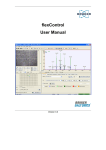


![1 Drücken Sie den [MEAS/ENTER]](http://vs1.manualzilla.com/store/data/006738652_1-b310a9229ce00e9c097e8c2e8ac6def9-150x150.png)