1
Premium
S1A34003 10/2014
Premium
TSX ETC 101
Ethernet Communication Module
User Manual
S1A34003.05
10/2014
www.schneider-electric.com
The information provided in this documentation contains general descriptions and/or technical
characteristics of the performance of the products contained herein. This documentation is not
intended as a substitute for and is not to be used for determining suitability or reliability of these
products for specific user applications. It is the duty of any such user or integrator to perform the
appropriate and complete risk analysis, evaluation and testing of the products with respect to the
relevant specific application or use thereof. Neither Schneider Electric nor any of its affiliates or
subsidiaries shall be responsible or liable for misuse of the information contained herein. If you
have any suggestions for improvements or amendments or have found errors in this publication,
please notify us.
No part of this document may be reproduced in any form or by any means, electronic or
mechanical, including photocopying, without express written permission of Schneider Electric.
All pertinent state, regional, and local safety regulations must be observed when installing and
using this product. For reasons of safety and to help ensure compliance with documented system
data, only the manufacturer should perform repairs to components.
When devices are used for applications with technical safety requirements, the relevant
instructions must be followed.
Failure to use Schneider Electric software or approved software with our hardware products may
result in injury, harm, or improper operating results.
Failure to observe this information can result in injury or equipment damage.
© 2014 Schneider Electric. All rights reserved.
2
S1A34003 10/2014
Table of Contents
Safety Information . . . . . . . . . . . . . . . . . . . . . . . . . . . . .
About the Book. . . . . . . . . . . . . . . . . . . . . . . . . . . . . . . .
Chapter 1 Installation. . . . . . . . . . . . . . . . . . . . . . . . . . . . . . . . . . . .
Hardware Installation . . . . . . . . . . . . . . . . . . . . . . . . . . . . . . . . . . . . . .
Module Specifications . . . . . . . . . . . . . . . . . . . . . . . . . . . . . . . . . . . . .
Communication Specifications . . . . . . . . . . . . . . . . . . . . . . . . . . . . . .
Installing Unity Pro Ethernet Configuration Tool Software . . . . . . . . .
UnInstalling the Ethernet Configuration Tool . . . . . . . . . . . . . . . . . . . .
Chapter 2 Configuring the Ethernet Communication Module . . .
2.1 Ethernet Network Configuration Example . . . . . . . . . . . . . . . . . . . . . .
The Ethernet Network Example. . . . . . . . . . . . . . . . . . . . . . . . . . . . . .
2.2 Creating a Project in Unity Pro . . . . . . . . . . . . . . . . . . . . . . . . . . . . . .
Creating a Project in Unity Pro . . . . . . . . . . . . . . . . . . . . . . . . . . . . . .
Configuring the Size and Location of Inputs and Outputs . . . . . . . . . .
2.3 The Unity Pro FDT/DTM Interface . . . . . . . . . . . . . . . . . . . . . . . . . . . .
DTM Browser. . . . . . . . . . . . . . . . . . . . . . . . . . . . . . . . . . . . . . . . . . . .
DTM Browser Menu Commands . . . . . . . . . . . . . . . . . . . . . . . . . . . . .
Field Bus Discovery Service . . . . . . . . . . . . . . . . . . . . . . . . . . . . . . . .
Device Editor . . . . . . . . . . . . . . . . . . . . . . . . . . . . . . . . . . . . . . . . . . . .
Configuring Properties in the Device Editor. . . . . . . . . . . . . . . . . . . . .
Uploading and Downloading DTM-Based Applications . . . . . . . . . . . .
2.4 Channel Properties . . . . . . . . . . . . . . . . . . . . . . . . . . . . . . . . . . . . . . .
Channel Properties Page . . . . . . . . . . . . . . . . . . . . . . . . . . . . . . . . . .
Channel Properties - Ethernet Page . . . . . . . . . . . . . . . . . . . . . . . . . .
Channel Properties - TCP/IP Page . . . . . . . . . . . . . . . . . . . . . . . . . . .
Channel Properties - EtherNet/IP Page. . . . . . . . . . . . . . . . . . . . . . . .
2.5 Ethernet Services . . . . . . . . . . . . . . . . . . . . . . . . . . . . . . . . . . . . . . . .
Enabling Services . . . . . . . . . . . . . . . . . . . . . . . . . . . . . . . . . . . . . . . .
Configuring Access Control . . . . . . . . . . . . . . . . . . . . . . . . . . . . . . . . .
Configuring the DHCP and FDR Servers . . . . . . . . . . . . . . . . . . . . . .
Configuring QoS Ethernet Packet Tagging . . . . . . . . . . . . . . . . . . . . .
Configuring the Email Service . . . . . . . . . . . . . . . . . . . . . . . . . . . . . . .
Sending Email via the SEND_REQ Block . . . . . . . . . . . . . . . . . . . . . .
Configuring the Network Time Service . . . . . . . . . . . . . . . . . . . . . . . .
Configuring the SNMP Agent . . . . . . . . . . . . . . . . . . . . . . . . . . . . . . .
S1A34003 10/2014
9
11
13
14
17
19
21
23
25
26
26
28
29
35
37
38
41
47
51
53
55
57
58
60
61
63
65
66
68
71
78
82
85
88
91
3
2.6 Security . . . . . . . . . . . . . . . . . . . . . . . . . . . . . . . . . . . . . . . . . . . . . . . .
Security Features . . . . . . . . . . . . . . . . . . . . . . . . . . . . . . . . . . . . . . . . .
2.7 Configuring the Ethernet Communication Module as an EtherNet/IP
Adapter. . . . . . . . . . . . . . . . . . . . . . . . . . . . . . . . . . . . . . . . . . . . . . . . .
Introducing the Local Slave . . . . . . . . . . . . . . . . . . . . . . . . . . . . . . . . .
Configuring a Local Slave . . . . . . . . . . . . . . . . . . . . . . . . . . . . . . . . . .
Local Slave Inputs and Outputs . . . . . . . . . . . . . . . . . . . . . . . . . . . . . .
Chapter 3 Adding Devices to an Ethernet Network . . . . . . . . . . .
3.1 Hardware Catalog . . . . . . . . . . . . . . . . . . . . . . . . . . . . . . . . . . . . . . . .
Adding a DTM to the Unity Pro Hardware Catalog . . . . . . . . . . . . . . .
Add an EDS File to the Unity Pro Hardware Catalog. . . . . . . . . . . . . .
Updating the Unity Pro Hardware Catalog . . . . . . . . . . . . . . . . . . . . . .
Remove an EDS File from the Unity Pro Hardware Catalog . . . . . . . .
3.2 Adding an EtherNet/IP Device to the Network . . . . . . . . . . . . . . . . . . .
Setting Up Your Network . . . . . . . . . . . . . . . . . . . . . . . . . . . . . . . . . . .
Adding an STB NIC 2212 Remote Device . . . . . . . . . . . . . . . . . . . . . .
Configuring STB NIC 2212 Properties . . . . . . . . . . . . . . . . . . . . . . . . .
Configuring EtherNet/IP Connections . . . . . . . . . . . . . . . . . . . . . . . . .
Connecting to the Advantys STB Island. . . . . . . . . . . . . . . . . . . . . . . .
Configuring I/O Items . . . . . . . . . . . . . . . . . . . . . . . . . . . . . . . . . . . . . .
3.3 Adding a Modbus TCP Device to the Network. . . . . . . . . . . . . . . . . . .
Setting Up Your Network . . . . . . . . . . . . . . . . . . . . . . . . . . . . . . . . . . .
Adding an STB NIP 2212 Remote Device . . . . . . . . . . . . . . . . . . . . . .
Configuring STB NIP 2212 Properties . . . . . . . . . . . . . . . . . . . . . . . . .
Connecting to the Advantys STB Island. . . . . . . . . . . . . . . . . . . . . . . .
Configuring I/O Items . . . . . . . . . . . . . . . . . . . . . . . . . . . . . . . . . . . . . .
Chapter 4 Working With Derived Data Types . . . . . . . . . . . . . . . .
Creating and Updating Derived Data Types . . . . . . . . . . . . . . . . . . . .
Working with Derived Data Type Variables . . . . . . . . . . . . . . . . . . . . .
Effect of Activating and De-activating Devices on I/O %MW Memory
Addresses . . . . . . . . . . . . . . . . . . . . . . . . . . . . . . . . . . . . . . . . . . . . . .
Chapter 5 Optimizing Performance . . . . . . . . . . . . . . . . . . . . . . . .
5.1 Selecting a Switch . . . . . . . . . . . . . . . . . . . . . . . . . . . . . . . . . . . . . . . .
Role of a Switch in an Ethernet Network . . . . . . . . . . . . . . . . . . . . . . .
Transmission Speed, Duplex and Auto-Negotiation . . . . . . . . . . . . . .
Quality of Service (QoS) . . . . . . . . . . . . . . . . . . . . . . . . . . . . . . . . . . .
IGMP Snooping . . . . . . . . . . . . . . . . . . . . . . . . . . . . . . . . . . . . . . . . . .
4
94
94
96
97
99
104
111
112
113
114
117
119
121
122
124
126
132
138
142
157
158
160
162
171
175
185
186
188
198
201
202
203
204
205
206
S1A34003 10/2014
Rapid Spanning Tree Protocol (RSTP) . . . . . . . . . . . . . . . . . . . . . . . .
Virtual Local Area Network (VLAN) . . . . . . . . . . . . . . . . . . . . . . . . . . .
Port Mirroring. . . . . . . . . . . . . . . . . . . . . . . . . . . . . . . . . . . . . . . . . . . .
Simple Network Management Protocol (SNMP) Agent . . . . . . . . . . . .
5.2 Control Application Design . . . . . . . . . . . . . . . . . . . . . . . . . . . . . . . . .
Message Types . . . . . . . . . . . . . . . . . . . . . . . . . . . . . . . . . . . . . . . . . .
Message Connection Types . . . . . . . . . . . . . . . . . . . . . . . . . . . . . . . .
TCP and CIP Connections . . . . . . . . . . . . . . . . . . . . . . . . . . . . . . . . .
Message Priority . . . . . . . . . . . . . . . . . . . . . . . . . . . . . . . . . . . . . . . . .
Messaging Performance . . . . . . . . . . . . . . . . . . . . . . . . . . . . . . . . . . .
Message Frequency . . . . . . . . . . . . . . . . . . . . . . . . . . . . . . . . . . . . . .
Allocating Network Bandwidth . . . . . . . . . . . . . . . . . . . . . . . . . . . . . . .
Estimating Message Traverse and Response Times . . . . . . . . . . . . .
5.3 Projecting Ethernet Network Performance . . . . . . . . . . . . . . . . . . . . .
Network Load and Bandwidth Calculation Example . . . . . . . . . . . . . .
Chapter 6 CIP Objects . . . . . . . . . . . . . . . . . . . . . . . . . . . . . . . . . . .
Identity Object . . . . . . . . . . . . . . . . . . . . . . . . . . . . . . . . . . . . . . . . . . .
Assembly Object . . . . . . . . . . . . . . . . . . . . . . . . . . . . . . . . . . . . . . . . .
Connection Manager Object . . . . . . . . . . . . . . . . . . . . . . . . . . . . . . . .
Modbus Object . . . . . . . . . . . . . . . . . . . . . . . . . . . . . . . . . . . . . . . . . .
Quality Of Service (QoS) Object . . . . . . . . . . . . . . . . . . . . . . . . . . . . .
TCP/IP Interface Object. . . . . . . . . . . . . . . . . . . . . . . . . . . . . . . . . . . .
Ethernet Link Object . . . . . . . . . . . . . . . . . . . . . . . . . . . . . . . . . . . . . .
EtherNet/IP Interface Diagnostics Object . . . . . . . . . . . . . . . . . . . . . .
EtherNet/IP IO Scanner Diagnostics Object . . . . . . . . . . . . . . . . . . . .
IO Connection Diagnostics Object. . . . . . . . . . . . . . . . . . . . . . . . . . . .
EtherNet/IP Explicit Connection Diagnostics Object . . . . . . . . . . . . . .
EtherNet/IP Explicit Connection Diagnostics List Object . . . . . . . . . . .
Chapter 7 Online Action . . . . . . . . . . . . . . . . . . . . . . . . . . . . . . . . .
Accessing CIP Objects . . . . . . . . . . . . . . . . . . . . . . . . . . . . . . . . . . . .
Editing Port Configuration Properties for Remote EtherNet/IP Devices
Pinging a Network Device . . . . . . . . . . . . . . . . . . . . . . . . . . . . . . . . . .
Viewing and Editing Online Settings for a Remote Device . . . . . . . . .
Chapter 8 Explicit Messaging . . . . . . . . . . . . . . . . . . . . . . . . . . . . .
8.1 Explicit Messaging Using the SEND_REQ Block . . . . . . . . . . . . . . . .
Configuring Explicit Messaging Using SEND_REQ . . . . . . . . . . . . . .
Configuring the SEND_REQ Management Parameter . . . . . . . . . . . .
S1A34003 10/2014
207
208
210
211
212
213
215
217
218
219
220
222
224
226
226
231
233
235
237
239
241
243
245
250
253
255
259
261
263
264
266
268
270
273
274
275
277
5
8.2 EtherNet/IP Explicit Messaging Using SEND_REQ. . . . . . . . . . . . . . .
Explicit Messaging Services. . . . . . . . . . . . . . . . . . . . . . . . . . . . . . . . .
Configuring EtherNet/IP Explicit Messaging Using SEND_REQ . . . . .
EtherNet/IP Explicit Message Example: Get_Attribute_Single . . . . . .
EtherNet/IP Explicit Message Example: Read Modbus Object . . . . . .
EtherNet/IP Explicit Message Example: Write Modbus Object . . . . . .
8.3 Modbus TCP Explicit Messaging Using SEND_REQ . . . . . . . . . . . . .
Modbus TCP Explicit Messaging Request Codes . . . . . . . . . . . . . . . .
Configuring Modbus TCP Explicit Messaging Using SEND_REQ . . . .
Modbus TCP Explicit Message Example: Read Registers . . . . . . . . .
Modbus TCP Explicit Message Example: Write Registers. . . . . . . . . .
Modbus TCP Explicit Message Example: Read Holding Registers . . .
Modbus TCP Explicit Message Example: Write Multiple Registers . . .
8.4 Explicit Messaging via the Unity Pro GUI. . . . . . . . . . . . . . . . . . . . . . .
Sending Explicit Messages to EtherNet/IP Devices. . . . . . . . . . . . . . .
Sending Explicit Messages to Modbus TCP Devices . . . . . . . . . . . . .
Chapter 9 Diagnostics. . . . . . . . . . . . . . . . . . . . . . . . . . . . . . . . . . .
9.1 Module Hardware Diagnostics . . . . . . . . . . . . . . . . . . . . . . . . . . . . . . .
LED Indicators for the Ethernet Communication Module . . . . . . . . . . .
9.2 Unity Pro Software Diagnostics . . . . . . . . . . . . . . . . . . . . . . . . . . . . . .
Using the Diagnostic Window . . . . . . . . . . . . . . . . . . . . . . . . . . . . . . .
Ethernet Port Diagnostics . . . . . . . . . . . . . . . . . . . . . . . . . . . . . . . . . .
Bandwidth Diagnostics. . . . . . . . . . . . . . . . . . . . . . . . . . . . . . . . . . . . .
Email Diagnostics. . . . . . . . . . . . . . . . . . . . . . . . . . . . . . . . . . . . . . . . .
Network Time Service Diagnostics . . . . . . . . . . . . . . . . . . . . . . . . . . .
Local Slave / Connection Diagnostics . . . . . . . . . . . . . . . . . . . . . . . . .
Local Slave or Connection I/O Value Diagnostics . . . . . . . . . . . . . . . .
Logging . . . . . . . . . . . . . . . . . . . . . . . . . . . . . . . . . . . . . . . . . . . . . . . .
9.3 CPU I/O Block Diagnostics . . . . . . . . . . . . . . . . . . . . . . . . . . . . . . . . .
Accessing the Unity Pro Diagnostic Tools . . . . . . . . . . . . . . . . . . . . . .
Communication Channel Diagnostics in Unity Pro. . . . . . . . . . . . . . . .
Communication Module Diagnostics in Unity Pro . . . . . . . . . . . . . . . .
Chapter 10 Replacing the Ethernet Communication Module . . . .
Replacing the Ethernet Communication Module . . . . . . . . . . . . . . . . .
6
278
279
281
283
288
293
298
299
300
302
304
306
308
310
311
314
317
318
318
320
321
324
328
331
333
336
340
342
344
345
348
351
357
357
S1A34003 10/2014
Chapter 11 Embedded Web Pages . . . . . . . . . . . . . . . . . . . . . . . . . .
11.1 Accessing the Embedded Web Server . . . . . . . . . . . . . . . . . . . . . . . .
Introducing the Embedded Web Pages . . . . . . . . . . . . . . . . . . . . . . . .
Accessing the Home Page . . . . . . . . . . . . . . . . . . . . . . . . . . . . . . . . .
Using and Editing a Username and Passwords . . . . . . . . . . . . . . . . .
11.2 Monitoring the Unity Pro Application . . . . . . . . . . . . . . . . . . . . . . . . . .
Using the Monitoring Page . . . . . . . . . . . . . . . . . . . . . . . . . . . . . . . . .
Data Editor (Standard). . . . . . . . . . . . . . . . . . . . . . . . . . . . . . . . . . . . .
Working With Data Templates . . . . . . . . . . . . . . . . . . . . . . . . . . . . . . .
Data Editor (Lite) . . . . . . . . . . . . . . . . . . . . . . . . . . . . . . . . . . . . . . . . .
11.3 Diagnostics . . . . . . . . . . . . . . . . . . . . . . . . . . . . . . . . . . . . . . . . . . . . .
Using the Diagnostics Page . . . . . . . . . . . . . . . . . . . . . . . . . . . . . . . .
Status Summary . . . . . . . . . . . . . . . . . . . . . . . . . . . . . . . . . . . . . . . . .
Rack Viewer . . . . . . . . . . . . . . . . . . . . . . . . . . . . . . . . . . . . . . . . . . . .
Processor Load . . . . . . . . . . . . . . . . . . . . . . . . . . . . . . . . . . . . . . . . . .
Scanner Status . . . . . . . . . . . . . . . . . . . . . . . . . . . . . . . . . . . . . . . . . .
Messaging . . . . . . . . . . . . . . . . . . . . . . . . . . . . . . . . . . . . . . . . . . . . . .
Ethernet Statistics . . . . . . . . . . . . . . . . . . . . . . . . . . . . . . . . . . . . . . . .
QoS Configuration . . . . . . . . . . . . . . . . . . . . . . . . . . . . . . . . . . . . . . . .
Email Diagnostics . . . . . . . . . . . . . . . . . . . . . . . . . . . . . . . . . . . . . . . .
Network Time Service Diagnostics . . . . . . . . . . . . . . . . . . . . . . . . . . .
Properties . . . . . . . . . . . . . . . . . . . . . . . . . . . . . . . . . . . . . . . . . . . . . .
Appendices
.........................................
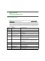
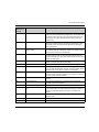
Appendix A Detected Error Codes. . . . . . . . . . . . . . . . . . . . . . . . . . .
Explicit Messaging: Communication and Operation Reports . . . . . . .
Sending Email via SEND_REQ: Communication and Operation
Reports . . . . . . . . . . . . . . . . . . . . . . . . . . . . . . . . . . . . . . . . . . . . . . . .
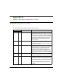
Appendix B CIP General Status Codes . . . . . . . . . . . . . . . . . . . . . . .
CIP General Status Codes . . . . . . . . . . . . . . . . . . . . . . . . . . . . . . . . .
Appendix C Modbus Exception Response Codes . . . . . . . . . . . . . .
MODBUS Exception Response Codes . . . . . . . . . . . . . . . . . . . . . . . .
Appendix D Email Detected Error Response Codes . . . . . . . . . . . .
Electronic Mail Notification Service Detected Error Response Codes
Glossary
Index
S1A34003 10/2014
.........................................
.........................................
359
360
361
362
363
366
367
368
373
377
379
380
381
384
386
389
391
393
396
398
401
403
405
407
408
411
413
413
417
417
419
419
421
423
7
8
S1A34003 10/2014
Safety Information
Important Information
NOTICE
Read these instructions carefully, and look at the equipment to become familiar with the device
before trying to install, operate, or maintain it. The following special messages may appear
throughout this documentation or on the equipment to warn of potential hazards or to call attention
to information that clarifies or simplifies a procedure.
S1A34003 10/2014
9
PLEASE NOTE
Electrical equipment should be installed, operated, serviced, and maintained only by qualified
personnel. No responsibility is assumed by Schneider Electric for any consequences arising out of
the use of this material.
A qualified person is one who has skills and knowledge related to the construction and operation
of electrical equipment and its installation, and has received safety training to recognize and avoid
the hazards involved.
10
S1A34003 10/2014
About the Book
At a Glance
Document Scope
This manual describes the use of the Premium TSX ETC 101 Ethernet communication module.
This manual describes the creation of a complete configuration. The features and functions of the
module are explained in the course of constructing this configuration.
The specific configuration settings contained in this manual are intended to be used for
instructional purposes only. The settings required for your specific configuration will differ from the
examples presented in this manual.
Validity Note
The Ethernet communication module described in this document requires Unity Pro version 8.0 or
later.
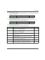
Related Documents
For additional information, refer to the online help files for the Unity Pro software, and to the
following technical publications:
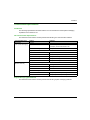
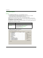
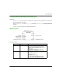
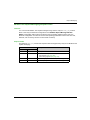
Title of Documentation
Reference Number
Advantys STB EtherNet/IP Network Interface Applications Guide
31008204
You can download these technical publications and other technical information from our website
at www.schneider-electric.com.
S1A34003 10/2014
11
12
S1A34003 10/2014
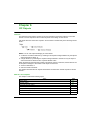
Premium
Installation
S1A34003 10/2014
Chapter 1
Installation
Installation
Overview
The Ethernet communication module serves as the interface between a Premium PLC and other
Ethernet network devices by means of either the EtherNet/IP or the Modbus TCP communication
protocol. This chapter shows you how to install the module by:
inserting it into a PLC backplane
connecting it to an Ethernet network
installing the Unity Pro Ethernet Configuration Tool software
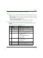
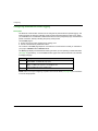
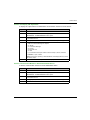
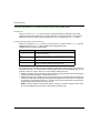
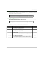
What Is in This Chapter?
This chapter contains the following topics:
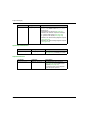
Topic
Page
Hardware Installation
14
Module Specifications
17
Communication Specifications
19
Installing Unity Pro Ethernet Configuration Tool Software
21
UnInstalling the Ethernet Configuration Tool
23
S1A34003 10/2014
13
Installation
Hardware Installation
Overview
The following information describes how to install the TSX ETC 101 Ethernet communication
module.
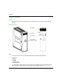
External Features
LEDs
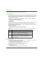
The TSX ETC 101 communication module presents the following LED indicators:
Running
Error
Status
Activity
Module Status
Network Status
For a description of these LEDs, and how to use them to diagnose the communication module,
refer to the topic LED Indicators for the Ethernet Communication Module (see page 318).
14
S1A34003 10/2014
Installation
Tools Required
One medium sized (size 2) Phillips-head screw driver.
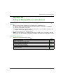
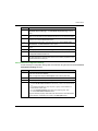
Mounting the Module
The module is mounted in the rack slot of a Premium or Atrium PLC station. It can be installed in
any available slot (except in the offset X Bus racks). To mount the communication module:
Step
Action
1
Place the prongs at the lower back of the
module into the centering holes on the
lower part of the rack.
2
Swivel the module up and back to bring it
into contact with the rack and the pin
connectors.
3
Tighten the screw on the upper part of the
module to hold the module in place on the
rack.
Note: Maximum tightening torque is
2.0. N.m. (17.7 lb-in)
S1A34003 10/2014
Illustration
15
Installation
Wiring the Ethernet Connector
WARNING
HAZARD OF ELECTRICAL SHOCK OR BURN
Connect the ground wire to the protective ground (PE) terminal before you establish any further
connections. When you remove connections, disconnect the ground wire last. For noise
immunity, EMC compliance, and safety, connect the Ethernet cable shield to PE ground at the
Ethernet switch.
Failure to follow these instructions can result in death, serious injury, or equipment
damage.
The TSX ETC 101 communication module communicates over an EtherNet/IP network through a
single RJ45 connector located in the upper half of the module.
16
S1A34003 10/2014
Installation
Module Specifications
Specifications
TSX ETC 101 specifications include:
Ports
Communication Ports
One auto-sensing 10/100Base-T shielded twisted pair (RJ-45
connector) port.
Electrical
Bus Current Required
@5V: 400 mA
Power Dissipation
2W
Fuse
None
Operating Conditions
Temperature
0...+60° C
Humidity
0...95% Rh non-condensing @ 60° C
Altitude
2000 m (6561.68 ft)
Storage Conditions
Temperature
–40...+85° C
Humidity
0...95% Rh non-condensing @ 60° C
Altitude
3000 m (9842.52 ft) transport
Software Compatibility
The Ethernet communication module is compatible with Unity Pro programming software version
5.0 and higher.
Standards
The Ethernet communication module complies with the following standards:
UL 508
CSA 22.2-142
CE
EMI EN55011
EN61131-2
FM 3611 Class 1 Div2 Groups ABCD
IEC61131-2
IEEE 802.3 2002
ODVA
S1A34003 10/2014
17
Installation
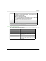
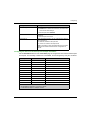
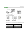
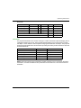
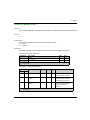
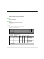
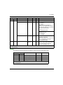
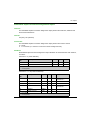
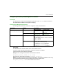
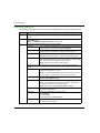
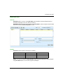
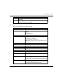
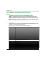
Communication Modules per Station
The maximum number of communication modules—including but not limited to TSX ETC 101
Ethernet communication modules—you can install in a single station is determined by the CPU
serving that station
18
CPU
Maximum Number of Communication Modules per Station
TSX H57 24
2
TSX H57 44
4
TSX P57 104
1
TSX P57 154
1
TSX P57 204
2
TSX P57 0244
1
TSX P57 254
2
TSX P57 304
3
TSX P57 354
3
TSX P57 454
4
TSX P57 554
4
TSX P57 1634
0
TSX P57 2634
1
TSX P57 3634
2
TSX P57 4634
3
TSX P57 5634
3
TSX P57 6634
3
S1A34003 10/2014
Installation
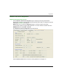
Communication Specifications
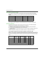
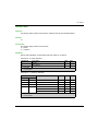
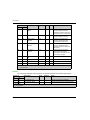
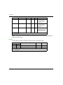
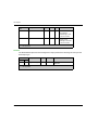
Introduction
The following specifications describe both the I/O communication and the explicit messaging
capacities of the TSX ETC 101.
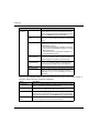
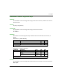
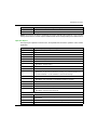
I/O Communication Specifications
The Ethernet communication module presents the following I/O communication features:
Communication type
Feature
EtherNet/IP
(CIP Implicit Messaging)
Scanner
Capacity
Maximum number of devices
128 devices (125 devices as scanner + 3 devices
as adapter) shared with Modbus TCP
Maximum message size
512 bytes
Adapter
Modbus TCP
(Modbus Scanner)
Maximum number of instances
3 adapter instances
Maximum number of connections
2 connections per instance
Maximum message size
511 bytes including header
Inputs
505 bytes excluding header
Outputs
509 bytes excluding header
Maximum number of registers
Read
125 registers
Write
120 registers
Maximum number of devices
128 devices shared with EtherNet/IP
Maximum message size
Read
250 bytes (125 words) excluding header
Write
240 bytes (120 words) excluding header
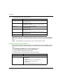
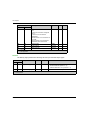
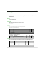
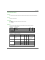
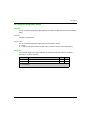
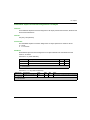
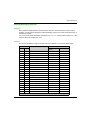
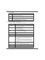
Explicit Messaging Specifications
The Ethernet communication module presents the following explicit messaging features:
S1A34003 10/2014
19
Installation
Communication type
Feature
EtherNet/IP
(CIP Explicit
Messaging)
Client
Capacity
Maximum number of simultaneous connections
16 connections
Maximum number of concurrent requests
16 requests, shared with Modbus TCP
Server
Maximum number of simultaneous connections
32 connections
Maximum messaging size
Modbus TCP
(Modbus Scanner)
Read
250 bytes
Write
240 bytes
Client
Maximum number of simultaneous connections
16 connections
Maximum number of concurrent requests
16 requests, shared with EtherNet/IP
Server
Maximum number of simultaneous requests
128 requests
Maximum number of simultaneous connections
32 connections
Maximum message size
20
Read
250 bytes (125 words) excluding header
Write
240 bytes (120 words) excluding header
S1A34003 10/2014
Installation
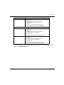
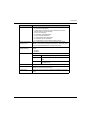
Installing Unity Pro Ethernet Configuration Tool Software
Overview
Accessing Unity Pro Configuration Tool Software depends on the version of Unity Pro that you are
using:
Unity Pro version 6.0 and higher: The module configuration software is already included in the
Unity Pro installation.
Unity Pro version 5.0: You need to install the Unity Pro Ethernet Configuration Tool software,
which you can obtain from the following website:
http://www.global-download.schneiderelectric.com/8525773E00058BDC/all/DA00A87B8BB30386852577940058D66C
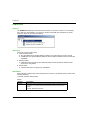
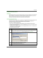
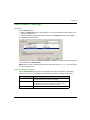
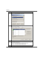
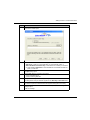
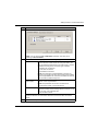
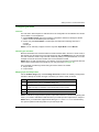
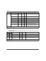
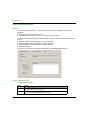
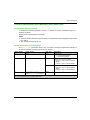
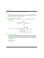
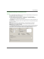
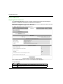
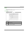
Installing Unity Pro Ethernet Configuration Tool Software for Unity Pro Version 5.0
To install this software, navigate to navigate to the root of the installation files and run the file
Setup.exe.
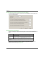
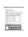
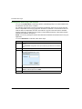
The setup process displays the following setup screens:
Step
Screen
Description
1
Welcome
Click Next to continue.
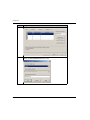
2
ReadMe and
Release Notes Display
Indicate whether to display the ReadMe file.
Click Next to continue.
3
ReadMe
(Optional) Displays the ReadMe file, if selected above.
Click Next to continue.
4
License Agreement
Displays the software license.
Select I accept..., then click Next to continue.
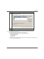
5
Customer Information
Enter the following data:
your first and last names
company name
identify for whom the software is installed:
anyone who uses this computer
only for yourself
Click Next to continue.
6
Destination Folder
Identify where the application will be installed. Either:
Accept the default path
Click Change... and specify a new path
Click Next to continue.
7
Ready to Install
Click Next to continue.
8
Status
Progress bar indicates the status of the installation.
When complete, click Next to continue.
9
Install Complete
Click Finish.
S1A34003 10/2014
21
Installation
The installation process described above copies the following objects to your PC:
the Unity Pro Ethernet Configuration Tool
a Generic EtherNet/IP DTM
a Generic Modbus TCP DTM
NOTE: A DTM is a small software driver that defines and enables a device.
Updating Hardware Catalog
For installations of Unity Pro version 5.0 and higher, the next step is to update the
Hardware Catalog. Updating the Hardware Catalog adds your new Ethernet communication
module to the list of available modules and devices that you can add to your Unity Pro application.
Refer to the topic Updating the Unity Pro Hardware Catalog (see page 117) for step-by-step
instructions.
22
S1A34003 10/2014
Installation
UnInstalling the Ethernet Configuration Tool
Introduction
Use the Add or Remove Programs utility provided by the Windows™ operating system to
uninstall the Unity Pro Ethernet Configuration Tool.
To completely uninstall the Ethernet Configuration Tool, remove each of the following three DTMs,
one at a time:
Un-Installing Ethernet Configuration Tool DTMs
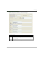
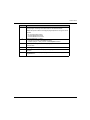
To remove the three Ethernet Configuration Tool DTMs:
Step
Action
1
Open the Windows Control Panel: Start →Settings →Control Panel.
2
In the Control Panel, double click on Add or Remove Programs.
3
In the Add or Remove Programs window, select the
Change or Remove Programs page.
4
Select the first of the three DTMs to remove (for example, the
Generic EtherNet/IP DTM), then click Remove.
5
Repeat step 4 for each of the remaining 2 DTMs: Generic Modbus DTM and
Unity Pro Ethernet Configuration Tool.
S1A34003 10/2014
23
Installation
24
S1A34003 10/2014
Premium
Configuring
S1A34003 10/2014
Chapter 2
Configuring the Ethernet Communication Module
Configuring the Ethernet Communication Module
Overview
This chapter shows you how to use Unity Pro programming software to select and configure the
Ethernet communication module.
NOTE: The instructions presented in this chapter include specific choices made for a sample
project. Your Unity Pro project may include different choices that are appropriate for your specific
configuration.
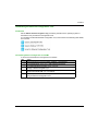
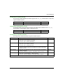
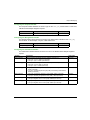
What Is in This Chapter?
This chapter contains the following sections:
Section
Topic
Page
2.1
Ethernet Network Configuration Example
26
2.2
Creating a Project in Unity Pro
28
2.3
The Unity Pro FDT/DTM Interface
37
2.4
Channel Properties
57
2.5
Ethernet Services
65
2.6
Security
94
2.7
Configuring the Ethernet Communication Module as an EtherNet/IP Adapter
96
S1A34003 10/2014
25
Configuring
Section 2.1
Ethernet Network Configuration Example
Ethernet Network Configuration Example
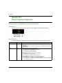
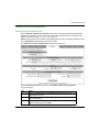
The Ethernet Network Example
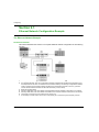
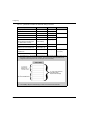
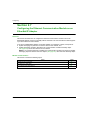
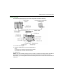
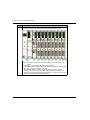
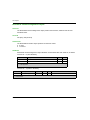
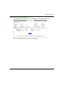
The Ethernet Network
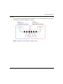
This manual describes the creation of a complete Ethernet network configuration for the following
topology:
1
2
3
4
5
6
7
26
Primary PLC incorporating the TSX ETC 101 Ethernet communication module
PC equipped with both Unity Pro configuration software (upgraded with the Ethernet Configuration Tool
that ships with the TSX ETC 101 Ethernet communication module), and Advantys configuration software,
used to configure communication settings for Ethernet communication module in the PLC (1) and the
remote network interface modules on the STB I/O islands (4 and 5, below)
Ethernet managed switch
Advantys STB island, with an STB NIC 2212 EtherNet/IP network interface module plus 8 I/O modules
Advantys STB island, with an STB NIP 2212 Modbus TCP network interface module plus 8 I/O modules
Third-party PLC that scans a local slave in the primary PLC
A secondary PLC that “listens” to the scan of the primary PLC local slave by the third-party scanner
S1A34003 10/2014
Configuring
Multiple Roles of the PLC and Ethernet Communication Module
The PLC, and in particular the TSX ETC 101 Ethernet communication module, can be configured
to simultaneously perform multiple roles with respect to other network devices. In this sample
network, you will learn how to configure the communication module to operate as:
a scanner of devices that use the EtherNet/IP (4) and the Modbus TCP (5) protocols
an adapter—also known as a local slave—that produces output data that both the remote thirdparty PLC (6) and secondary PLC (7) can read as input data
a DHCP server that provides IP address settings to other devices on the Ethernet network
an FDR server that provides operational settings to the devices on the Ethernet network that
also receive their IP addresses from the DHCP server, above
S1A34003 10/2014
27
Configuring
Section 2.2
Creating a Project in Unity Pro
Creating a Project in Unity Pro
Overview
This section shows you how to add modules—including the TSX ETC 101 Ethernet
communication module—to your project, using Unity Pro.
NOTE: For detailed information about how to use Unity Pro, refer to the online help and
documentation DVD that come with Unity Pro.
What Is in This Section?
This section contains the following topics:
Topic
28
Page
Creating a Project in Unity Pro
29
Configuring the Size and Location of Inputs and Outputs
35
S1A34003 10/2014
Configuring
Creating a Project in Unity Pro
Introduction
This topic shows you how to create a new Unity Pro project, and add to the new project the
following components:
a CPU
a power supply
a TSX ETC 101 Ethernet communication module
NOTE: The following example uses Unity Pro version 7.0, or higher.
Creating and Saving a New Unity Pro Project
Use Unity Pro to create a new project. The following steps describe the creation of a project for the
sample network:
Step
Action
1
Open Unity Pro.
2
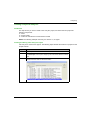
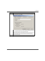
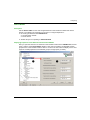
In the Unity Pro main menu, select File →New....
The New Project window opens displaying a list of Schneider-Electric controller
types.
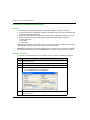
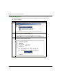
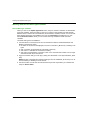
3
In the New Project window, expand the Premium node and select a CPU. In this
example, select the TSX P57 4634M controller:
S1A34003 10/2014
29
Configuring
Step
Action
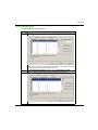
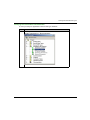
4
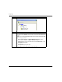
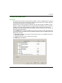
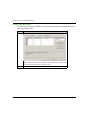
Click OK. Unity Pro displays the Project Browser, below.
5
To save the project, select File →Save. The Save As dialog opens.
6
In the Save As dialog, type in a File name—which will be the name of your Unity
Pro project—then click Save. Unity Pro saves your project to the specified path
location.
NOTE: You can change the default location Unity Pro uses to store project files.
Before saving your project:
1 Select Tools →Options. The Options Management window opens.
2 In the left pane, navigate to Options →General →Paths.
3 In the right pane, type in a new path location for the Project path. You can
also edit the:
Import/Export file path
XVM path
Project settings templates path
4 Click OK close the window and save your path edits.
30
S1A34003 10/2014
Configuring
Adding a Power Supply to the New Unity Pro Project
When you added the CPU to the project, above, Unity Pro may also have added a power supply
to the project. If not, the next step is to manually add a power supply to your Unity Pro project:
Step
Action
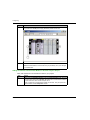
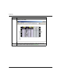
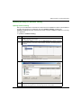
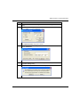
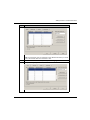
7
In the Project Browser, double click Local Bus. Unity Pro displays both the:
Local Bus window with the selected CPU in the second position, and
Hardware catalog displaying the Local Bus tab, below:
S1A34003 10/2014
31
Configuring
Step
Action
8
In the Hardware catalog, under the Supply node, use your mouse to select then
drag a TSX PSY 2600M power supply to the first position in the rack.
9
In the File menu, select Save, to save your edits.
NOTE: Schneider-Electric recommends that you periodically save your changes
as you make edits.
Adding an Ethernet Communication Module to the New Unity Pro Project
Next, add an Ethernet communication module to your project:
32
Step
Action
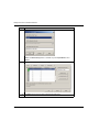
10
Returning to the Hardware catalog, under the Communication node, use your
mouse to select then drag a TSX ETC 101.2 Ethernet communication module to
an open slot in the rack—in this example, slot 2.
When you drop the communication module into the rack, Unity Pro opens the
communication module Properties window.
S1A34003 10/2014
Configuring
Step
Action
11
In the General page of the module properties window, type in an alias name for
the communication module: ETC01:
When you change the alias name, Unity Pro changes the base input and output
type and variable names to match the edited alias name.
NOTE: Schneider Electric recommends that you assign a unique alias name to
each communication module.This practice helps you distinguish between
modules of the same type.
12
S1A34003 10/2014
In the File menu, select Save, to save your edits.
33
Configuring
34
Step
Action
13
Click OK to close the Properties window. The Local Bus now displays the three
modules you have added:
14
The next step is to configure the located memory space in the CPU for the
communication module’s inputs and outputs (see page 35).
S1A34003 10/2014
Configuring
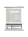
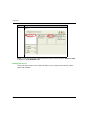
Configuring the Size and Location of Inputs and Outputs
Overview
Use the Configuration page of the communication module’s Properties window to configure:
the size and starting address of inputs
the size and starting address of outputs
The following steps present one example of how to configure the size and location of inputs and
outputs. Your own project configuration may differ.
Setting Input and Output Memory Addresses and Naming the Module
The Properties window opens when you double-click the left mouse button on the image of the
TSX ETC 101 communication module in either the Local Bus window, or the Project Browser.
When you select the Configuration page, it displays the network—or Alias—name. This is the
name assigned to the network channel when the communication module was added to the project.
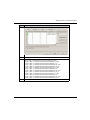
Use the Configuration page to edit the communication module inputs and outputs, as follows:
To input the above settings, take the following steps:
Step
Action
1
In the communication module’s Properties window, select the Configuration
page.
S1A34003 10/2014
35
Configuring
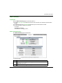
Step
Action
2
Type in the size and starting position of the inputs and outputs, as follows:
In the Inputs area:
In the %MW index field, type in a starting address for inputs—in this
example: 1.
In the Max size field, type in the maximum number of 16-bit words dedicated
to inputs—in this example:100.
In the Outputs area:
In the %MW index field, type in a starting address for outputs—in this
example: 101.
In the Max size field, type in the maximum number of 16-bit words dedicated
to outputs—in this example: 100.
Notes:
The inputs and outputs can be located at any available address. Allow
separateness-overlapping space to inputs and outputs, It is important only
that the space allocated to inputs and outputs do not overlap.
Unity Pro automatically reserves space for two arrays of 32 bytes, as follows:
for connection health bits (see page 191), located at the beginning of the
space configured for inputs
for connection control bits (see page 195), located at the beginning of the
space configured for outputs
Confirm that the %MW range you assign to both inputs and outputs is
available in the CPU. For more information, refer to the Unity Pro help file
topic Processor Configuration Screen.
3
In Unity Pro select Edit →Validate (or click the Validate
the address and size settings for inputs and outputs.
button) to save
Completing the Ethernet Network Configuration
After configuring settings for inputs and outputs, the next step is to configure the communication
module settings—beginning with Channel Properties—and then configure remote Ethernet
network devices (see page 111).
NOTE: After you input configuration settings for the communication module and remote devices,
return to the Configuration page of the communication module’s Properties window and click the
Update application button. This creates derived data type (DDT) variables (see page 186) that
display the following information and commands for your Unity Pro project:
36
connection health bits, that display the status of each connection
connection control bits, you can use to toggle each connection on and off
the value of input and output items
module and device configuration settings
free memory space that has been reserved, but not yet allocated
S1A34003 10/2014
Configuring
Section 2.3
The Unity Pro FDT/DTM Interface
The Unity Pro FDT/DTM Interface
Overview
The section describes the use of DTMs within Unity Pro.
What Is in This Section?
This section contains the following topics:
Topic
Page
DTM Browser
38
DTM Browser Menu Commands
41
Field Bus Discovery Service
47
Device Editor
51
Configuring Properties in the Device Editor
53
Uploading and Downloading DTM-Based Applications
55
S1A34003 10/2014
37
Configuring
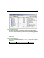
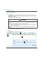
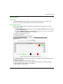
DTM Browser
Overview
The DTM Browser displays a hierarchical list of DTMs—in the form of nodes on a connectivity
tree—that have been added to your Unity Pro project. Each DTM node represents an actual
module or device in your Ethernet network.
Node Types
There are 3 types of DTM nodes:
Communication DTMs:
Any COM DTM can be plugged directly under the root node (Host PC) at the 1st level
A COM DTM can support Gateway DTMs or Device DTMs as children if their protocols are
compatible
Gateway DTMs:
A Gateway DTM can support other Gateway DTMs or Device DTMs as children if their
protocols are compatible.
Device DTMs:
A Device DTM does not support any child DTMs
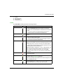
Node Names
Each DTM has a default name when inserted into the browser. The default name consists of the
following elements:
<Channel: Address> Device Name
Where:
38
Element
Description
channel
This is the name of the channel communication media, to which the device
is plugged in. This name is read from the DTM and is set by the device
vendor.
Example: EtherNet/IP, Modbus
S1A34003 10/2014
Configuring
Element
Description
address
The bus address of the device, which can be:
The connection point on its parent gateway network
The slot number in the modular device parent internal bus
Example: the device IP address
device name
The default name is determined by the vendor in the device DTM, but can
be edited by the user.
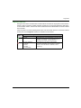
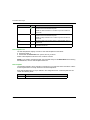
Node Status
The DTM Browser displays the status of each DTM node in the connectivity tree, as follows:.
Status
Description
Built / Not-built
A blue check mark
superimposed on a device icon
indicates that node, or one of its sub-nodes, is not built. This
means that some property of the node has changed, and the
information stored in the physical device is no longer
consistent with the local project.
Connected / Disconnected
A connected DTM is denoted in bold text. An unconnected
DTM appears in plain text.
NOTE:
Connecting a DTM to its physical device automatically
connects higher level parent nodes up to the root node.
Disconnecting a DTM from its physical device
automatically disconnects its lower level child nodes.
NOTE: Connecting or disconnecting a DTM to or from its
device does not also connect or disconnect Unity Pro to or
from the PLC. DTMs can be connected/disconnected while
Unity Pro is either offline or online.
Installed / Not-installed
A red superimposed on a device icon indicates the DTM for
that device is not installed on the PC.
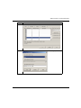
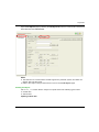
Handling Invalid Nodes
As indicated above, a red superimposed on a node indicates the DTM for that node is not
installed on the PC. To resolve this situation, click the right mouse button on the node to open a
pop-up menu with the following two commands:
Command
Description
Delete
Removes the selected node (and its sub-nodes) from the DTM Browser.
S1A34003 10/2014
39
Configuring
40
Command
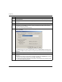
Description
Properties
Opens the following dialog, which you can use to identify the name of the
missing DTM:
S1A34003 10/2014
Configuring
DTM Browser Menu Commands
Overview
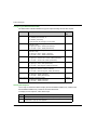
The DTM Browser includes a pop-up, contextual (right-click) menu that displays commands for
the currently selected DTM. The list of available commands consists of:
universal commands, as determined by the selected node level:
host PC node (level 1)
communication module node (level 2)
remote device node (level 3)
device-specific commands, as determined by the device DTM
Host PC Node Commands
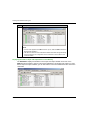
The Host PC node contextual menu includes the following commands:
Name
Add
1
Check DTM
devices1
Description
Opens the Add dialog — containing a subset of the Hardware
Catalog, allowing the selection of a communication module DTM.
Checks the current project for invalid DTMs or DTMs that are not
installed in the PC. If the results of the check include invalid or notinstalled DTMs, they are displayed in the User errors tab in the
information window and a red
DTM Browser.
is superimposed over their icons in the
DTM services
Displays the communication DTMs selection, as well as the device
topology, their respective IP addresses, and connection state. In this
dialog, for each device you can connect, disconnect, load from devices,
or store to devices. You can also choose to stop communication or
continue activity when detected errors occur.
DTM hardware
catalog
Displays the DTM catalog tab of the Hardware Catalog dialog.
Expand all2
Displays every DTM in the project.
Collapse all2
Displays only the communication DTMs in the project.
1. This command also appears in the Unity Pro Edit menu.
2. This command also appears in the Unity Pro View menu.
S1A34003 10/2014
41
Configuring
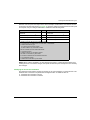
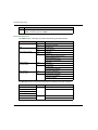
Communication Module and Remote Device Node Commands
The DTM Browser’s contextual menu has the following items:
Name
Open
1
Description
This opens the Device Editor for the selected communication module.
NOTE: Double-clicking the left mouse button on the DTM in the DTM Browser also
opens this window.
Add 1
This opens the Add dialog, displaying a subset of the Hardware Catalog, allowing
the selection of a DTM.
NOTE: Unity Pro filters the content of the Add dialog, so that it displays only DTMs
that are compatible with the selected DTM selected.
Delete1
If the selected DTM allows this function, this deletes the selected DTM and its subnode DTMs from the DTM connectivity tree.
Deletion from the DTM connectivity tree does not affect the DTM’s link to the I/O
scanning table.
Field Bus
Discovery
This scans the connected physical devices to create the corresponding field bus
topology. Refer to the Field Bus Discovery Service topic.
Connect1
This connects the DTM (see page 45) to its physical device on the network. This
connection does not depend on the PLC online/offline status of the Unity Pro project
application.
NOTE: Connecting a gateway or device DTM implicitly connects its parent DTM.
Disconnect1
This disconnects the DTM (see page 45) from its physical device. This
disconnection depends on the PLC online/offline status of the Unity Pro project
application.
NOTE: Disconnecting a gateway or device DTM implicitly disconnects its parent
DTM.
Load data from
This loads data from the physical device on the network to the DTM.
device1
Store data to
This loads data from the DTM to the physical device on the network.
device1
Copy
This command is disabled.
Paste
This command is disabled.
Device menu
This command opens a sub-menu that contains device-specific commands, as
determined by the device vendor.
For details, refer to the Communication Module Commands topic (see page 43).
Device menu 2
This command opens a sub-menu that contains device-specific commands, as
determined by the device vendor.
For details, refer to the Communication Module Commands topic (see page 43).
Properties1
Opens the Ethernet communication module Properties window.
1. This command also appears in the Unity Pro Edit menu.
2. This command also appears in the Unity Pro View menu.
42
S1A34003 10/2014
Configuring
Name
Description
Print device1
If this optional function is supported by a DTM, this function displays the device
documentation — including configuration settings — in the PC’s default Internet
browser, which can then be printed.
NOTE: Device information can be printed:
for only one device DTM at a time, when that DTM is not open for editing in the
Device Editor.
only when the DTM is disconnected from the physical device.
Zoom out2
This returns to the display of the entire DTM connectivity tree.
Expand all2
This displays DTMs below the selected DTM.
Collapse all2
This displays only the selected DTM.
1. This command also appears in the Unity Pro Edit menu.
2. This command also appears in the Unity Pro View menu.
Communication Module Commands
When you select Device menu in the main contextual menu for the communication module, a submenu with the following commands is displayed:
Name
Description
Offline Parameter
This command is disabled.
Online Parameter
This command is disabled.
Compare
This compares 2 devices, either online or offline.
Configuration
This opens the Device Editor for the selected
communication module, when the module and its DTM
are disconnected.
Observe
This command is disabled.
Diagnosis
This opens the Diagnosis Window for the selected
communication module, when the module and its DTM
are connected.
S1A34003 10/2014
43
Configuring
Name
Additional
functions
Description
Add EDS to library
Opens the EDS File Wizard, which you can use to add
a device EDS file to the Unity Pro EDS device library.
Unity Pro displays the contents of EDS files as DTMs for
use in the DTM Browser and Device Editor.
Remove EDS from
library
Opens the EDS Deletion from Device Library window,
which you can use to delete an EDS file from the device
library.
Online Action
Opens the Online Action window. Depending upon the
protocol(s) a remote device supports, you can use the
Online Action window to:
Ping a remote EtherNet/IP or Modbus TCP device
view and write to EtherNet/IP properties in a remote
EtherNet/IP device
view and write to port configuration properties in a
remote EtherNet/IP device
EtherNet/IP
Explicit Message
Opens the EtherNet/IP Explicit Message
(see page 311) window, which you can use to send
explicit messages to EtherNet/IP remote devices.
Modbus TCP
Explicit Message
Opens the Modbus TCP Explicit Message
(see page 314) window, which you can use to send
explicit messages to Modbus TCP remote devices.
About
Advanced Mode
Displays or hides expert-level properties that help define
Ethernet connections. See the Enabling Advanced
Mode topic (see page 46) for instruction on how to use
this feature.
When you select Device menu 2 in the main contextual menu for the communication module, a
sub-menu with the following commands is displayed:
44
Name
Description
Configuration
This opens the Device Editor for the selected communication module,
when the module and its DTM are disconnected.
Diagnosis
This opens the Diagnosis Window for the selected communication
module, when the module and its DTM are connected.
Add EDS to library
Opens the EDS File Wizard, which you can use to add a device EDS
file to the Unity Pro EDS device library. Unity Pro displays the contents
of EDS files as DTMs for use in the DTM Browser and Device Editor.
Remove EDS from
library
Opens the EDS Deletion from Device Library window, which you
can use to delete an EDS file from the device library.
S1A34003 10/2014
Configuring
Name
Description
Online Action
Opens the Online Action window. Depending upon the protocol(s) a
remote device supports, you can use the Online Action window to:
Ping a remote EtherNet/IP or Modbus TCP device
view and write to EtherNet/IP properties in a remote EtherNet/IP
device
view and write to port configuration properties in a remote
EtherNet/IP device
EtherNet/IP
Explicit Message
Opens the EtherNet/IP Explicit Message (see page 311) window,
which you can use to send explicit messages to EtherNet/IP remote
devices.
Modbus TCP
Explicit Message
Opens the Modbus TCP Explicit Message (see page 314) window,
which you can use to send explicit messages to Modbus TCP remote
devices.
Advanced Mode
Displays or hides expert-level properties that help define Ethernet
connections. See the Enabling Advanced Mode topic (see page 46)
for instruction on how to use this feature.
Connecting and Disconnecting a Device or Module DTM
A device or module DTM can be either connected to, or disconnected from, the physical device or
module.
When a device and its DTM are...
You can use the Ethernet configuration tool to...
Connected
Monitor and diagnose the real-time operation of the
device or module
Disconnected
Configure a communication module or remote device
by editing its properties
NOTE: Distinguish between:
connecting and disconnecting a DTM and the associated physical device using commands in
the DTM Browser
— and —
placing Unity Pro in online or offline operating mode using commands in the Unity Pro PLC
menu
You can connect a DTM to, or disconnect a DTM from a device or module using the contextual
pop-up menu in the DTM Browser. The DTM Browser indicates the relationship between the
DTM and the remote module or device: a connected DTM is displayed in bold text; a disconnected
DTM is displayed in normal text.
S1A34003 10/2014
45
Configuring
To connect a DTM to, or disconnect a DTM from its respective module or device, follow these
steps:
Step
Action
1
In the DTM Browser select the DTM that you want to connect to, or disconnect
from, the physical communication module or remote device.
NOTE: If the module or device name appears in:
bold text, it is connected and only the Disconnect command is enabled.
normal text, it is disconnected and only the Connect command is enabled.
2
Click the right-mouse button.
Result: A pop-up menu opens.
3
Select one of the following commands:
Connect
Disconnect
NOTE: The Connect and Disconnect commands are also available in the Unity
Pro Edit menu.
Enabling Advanced Mode
Use the contextual menu in the DTM Browser to toggle Unity Pro in or out of Advanced Mode,
thereby displaying or hiding expert-level properties that help define Ethernet connections. These
properties are identified by the
icon.
NOTE: To maintain system performance, confirm that Advanced Mode properties are configured
only by persons with a solid understanding of communication protocols.
To toggle Advanced Mode on and off:
Step
Action
1
Close both the Diagnosis Window and every instance of the Device Editor
before attempting to toggle Advanced Mode on or off.
NOTE: If the Device Editor or the Diagnosis Window is open, the
Advanced Mode status — on or off — cannot be changed.
46
2
In the DTM Browser, right-click the communication module.
Result: A pop-up menu opens.
3
To toggle ON advanced mode, select Device Menu →Advanced Mode.
4
To toggle OFF advanced mode, repeat steps 1 through 3, above.
S1A34003 10/2014
Configuring
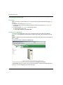
Field Bus Discovery Service
Introduction
Use the field bus discovery service to detect and add to your Unity Pro application, network devices
that are situated on a local network. The field bus discovery service is available only when the
Ethernet communication module DTM is connected to its physical device.
Only the first level devices below the communication DTM are detected.
Performing Field Bus Discovery
The results of the scanning process is compared to the registered DTMs in the DTM catalog of the
computer. If a match is found in the DTM catalog for a scanned device, the results are
accompanied with a matching type that gives the accuracy of the match.
These are the available matching types:
Exact match: Every identification attribute matches. The correct device type was found.
Generic match: At least the Vendor and device Type ID attributes match. The support level of
the DTM is “Generic Support.”
Uncertain match: At least the Vendor and device Type ID attributes match. The support level
of the DTM is not “Generic Support.”
Use the field bus discovery service:
Step
Action
1
In the DTM Browser, select an appropriate DTM.
NOTE: The field bus discovery service limits its search to the range of IP addresses that is preconfigured for the selected channel in the Channel Properties page (see page 58).
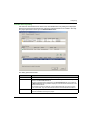
2
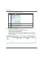
Right-click the DTM and scroll to Field bus discovery to open the dialog box:
3
Under these conditions, select a channel and a protocol:
The DTM has more than one channel.
The channel supports more than one protocol.
4
Click on OK. The service starts to detect devices on the selected channel.
S1A34003 10/2014
47
Configuring
Step
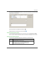
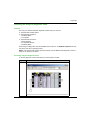
Action
5
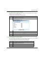
If at least one matched device has been found, the Field Bus Discovery dialog displays a list of
Scanned Devices.
6
Use the controls of the Field Bus Discovery dialog to select the devices to add to your Unity Pro
application.
7
After you have selected the devices you want to add in the Field Bus Discovery dialog, click OK.
8
If the field bus discovery process finds at least one device with an IP address that is already used
in the project, you are asked if you want to continue and replace the existing project device(s):
Yes: Proceed to the next step.
No: Cancel automatic field bus discovery.
9
The device properties dialog (below) opens, displaying the default name for the first discovered
device to be added:
In the General page of the device properties dialog, type in the Alias name for the device to be
added, then click OK. The dialog closes, then re-opens if there is another device to be added to the
application.
48
10
Repeat the above step for each additional discovered device.
11
After you finish adding devices to the application, configure each device for operation as part of the
application:
Disconnect the Ethernet communication module from its DTM. In the DTM Browser, select the
Ethernet communication module, then select Edit →Disconnect.
Configure the new device properties in the DTMs for both the Ethernet communication module,
and the newly added remote device.
S1A34003 10/2014
Configuring
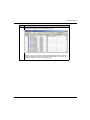
Field Bus Discovery Dialog
If at least one matched device has been found, the Field Bus Discovery dialog box is displayed
listing the scanned and matched devices. Select the matched devices to be created in the Unity
Pro project (which then shows up in the Selected Devices list:
This dialog presents these lists:
List
Description
Scanned Devices
The devices (matched and unmatched) found during the scan.
Matched Devices
The matched DTMs found in the workstation DTM catalog for the device that you
selected in the Scanned Devices list.
Each time a scanned device is selected in the Scanned Devices list, the contents of
the Matched Devices list is updated to display the matched device DTMs found for the
selected scanned device.
The matching process can yield one or more matched devices for a given scanned
device. In this case, only one DTM was discovered for the selected scanned device.
Selected Devices
This list displays the device DTMs that have been selected in the Matched Devices list,
which will be added to the Unity Pro project.
S1A34003 10/2014
49
Configuring
The lists use the following colored icons:
Color
Meaning
Green
The device has been selected.
Yellow
The device has been matched.
Red
The device has not been matched.
Black
Information about the address of the scanned device:
In the Scanned Devices list, the device has an address identical to one of the DTMs in
the Unity Pro project
In the Matched Devices list, the device will be assigned an address identical to one of
the DTMs in the Unity Pro project
NOTE: An icon can consist of two colors. For example, a search can discover a device that:
has a matching DTM, and
has an IP address identical to a device already added to the Unity Pro application
In this case, the icon next to the discovered device would be:
half yellow and half black before it is selected, and
half green and half black after it is selected
This dialog has five buttons:
50
Button
Use this button to...
Add All
Automatically add the most closely matched (according to the matching types listed above)
device DTM for each found device in the Matched Devices list to the Selected Devices list.
Add One
Add the matched device DTM selected in the Matched Devices list.
Remove
Remove one or more devices from the Selected Devices list.
OK
Insert the device DTMs in the Selected Devices list into the Unity Pro project.
If there are one or more devices in the Selected Devices list that have the same address in
the Unity Pro project, a message box opens asking if you want to continue.
If you click OK, devices in the Unity Pro project that have identical addresses as the selected
devices are deleted and replaced by the DTMs selected in the Selected Devices list.
Cancel
Cancel the field bus discovery scan and do nothing. Information in the three lists is discarded.
S1A34003 10/2014
Configuring
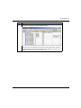
Device Editor
Description
Use the Device Editor to view and configure Ethernet communication modules and remote
devices. The collection of properties you can view or configure depends on:
the node type selected in the DTM Browser:
communication module
remote device
whether Unity Pro is operating in Advanced Mode
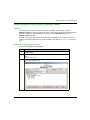
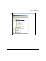
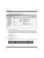
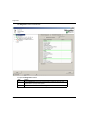
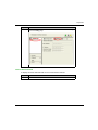
Displaying Properties of the Ethernet Communication Module
After you open the TSX ETC 101 Ethernet communication module in the DTM Browser, the left
pane (1, below) of the Device Editor displays a tree control containing configurable property
groups for the communication module. Click on a node in the tree control to display one or more
pages of module properties for the selected group in the right pane (2, below).
S1A34003 10/2014
51
Configuring
Property Types
The Device Editor displays an icon next to many device properties. The following three icons are
displayed:
This icon...
Indicates the property is...
Read-only. The property value cannot be edited in this page.
Read-write. The property value can be edited in this page.
An expert-level communication protocol property that is displayed only when
Advanced Mode is enabled.
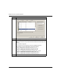
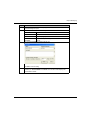
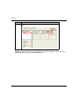
Displaying Property Definitions
Many property configuration pages provide an on-screen definition of the property you are editing.
To display a property definition in the Description section of the page, select that property in the
property list. The following screen displays a description of the Gateway IP Address property.
NOTE: The page displayed above can be accessed by opening an Ethernet communication
module in the Device Editor, and then selecting Channel Properties →TCP/IP in the navigation
tree.
52
S1A34003 10/2014
Configuring
Configuring Properties in the Device Editor
Configuring Properties
The Device Editor can be opened from the DTM Browser.
To open the DTM Browser select Tools →DTM Browser in the Unity Pro main menu.
To use the Device Editor:
Step
Description
1
Confirm that the DTM you want to use is not connected to the actual communication module or device. If
necessary, disconnect the DTM from the module or device (see page 45).
2
In the DTM Browser, select the Ethernet network node you want to configure, which can be either:
an Ethernet communication module
— or —
a remote device
3
With a node selected in the DTM Browser, do one of the following:
In the Unity Pro main menu, select Edit →Open.
— or —
In the DTM Browser click the right mouse button and, in the pop-up menu, select Open.
The Device Editor appears. It displays the configurable properties for the selected module or device:
S1A34003 10/2014
53
Configuring
Step
Description
4
Expand the navigation tree and select a node in the left window pane to display its properties in the right
pane. The list of configurable properties varies, depending on the node type — communication module or
remote device — selected in the DTM Browser.
5
While you edit a parameter, Unity Pro displays an icon — next to the field you are editing and in the
navigation tree — indicating the parameter value is being edited. Unity Pro displays one of the following
icons:
This icon...
Indicates the importance of the parameter being edited is...
High: Editing this parameter may limit or deny access to the module or device.
Low: Editing this parameter will not limit or deny access to the module or device.
6
After you finish editing a page, click:
Apply to save your edits and keep the page open.
— or —
OK to save your edits and close the page.
NOTE: Your edits will not take effect until they are successfully downloaded from your PC to the CPU and
from the CPU to the communication modules and network devices.
54
S1A34003 10/2014
Configuring
Uploading and Downloading DTM-Based Applications
Introduction
You can use Unity Pro to download an application file from your PC to the PLC, and to upload an
application file from the PLC to your PC.
To perform a successful upload, confirm that the application file includes specific upload-related
information as part of the application.
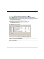
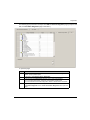
Downloading DTM-Based Applications
Unity Pro applications that include DTM files require more memory than traditional Unity Pro
applications. The following products employ DTMs for network configuration:
140 NOC 771 01 Ethernet Communication Module for Quantum
TSX ETC 101 Ethernet Communication Module for Premium
BMX NOC 0401 Ethernet Communication Module for M340
In some cases, the configurations created for these modules—and the data associated with
them—will require more memory than is available in the CPU.
If the amount of memory required by an application exceeds the amount of memory that is
available in the CPU, Unity Pro displays a message during the build process, before the application
is downloaded to the PLC.
When this situation occurs, exclude the additional upload-related information from the application
to complete the build and enable the application download. To do this, make the following
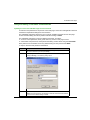
configuration change in Unity Pro:
Step
Action
1
In the main menu, select Tools →Project Settings... The Project Settings window
opens.
2
In the left pane of the Project Settings window, select General →
PLC embedded data.
S1A34003 10/2014
55
Configuring
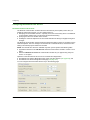
Step
Action
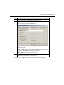
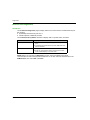
3
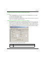
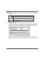
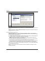
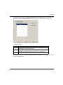
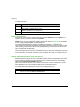
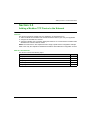
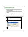
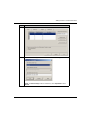
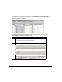
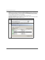
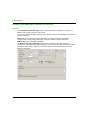
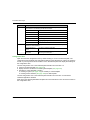
In the right pane, de-select Upload information:
4
Click OK to save your changes and close the Project Settings window.
After the Upload information setting is disabled, you can build the application and download it to
the PLC.
NOTE: An application in which the Upload information setting has been disabled cannot later be
uploaded from the PLC to the PC.
Uploading DTM-Based Applications
DTM-based applications that were successfully downloaded to Unity Pro—with the project’s
Upload information setting enabled—can later be uploaded from the PLC to the PC if the target
PC has the following files installed on it:
a version of Unity Pro that is equal to or higher than the version used to create the application
the master DTMs for the modules included in the configuration
NOTE: The Ethernet Configuration Tool installation CD contains the Master DTMs for the
Ethernet communication modules, referenced above.
the device DTMs for the DTM-based devices attached to the network (confirm that the DTMs
are of the same or higher revision as each device DTM used in the configuration)
the device EDS files for any EtherNet/IP device used in the configuration (confirm that the EDS
files are of the same or higher revision as each device EDS file used in the configuration)
After the above components have been installed on the target PC, you can upload a DTM-based
Unity Pro application from a PLC.
NOTE: Confirm that each of the above DTM components is installed on the target PC before
attempting the upload.
56
S1A34003 10/2014
Configuring
Section 2.4
Channel Properties
Channel Properties
Overview
This section describes how to configure channel properties for the Ethernet network.
What Is in This Section?
This section contains the following topics:
Topic
Page
Channel Properties Page
58
Channel Properties - Ethernet Page
60
Channel Properties - TCP/IP Page
61
Channel Properties - EtherNet/IP Page
63
S1A34003 10/2014
57
Configuring
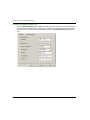
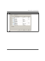
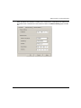
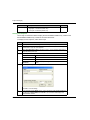
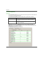
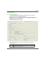
Channel Properties Page
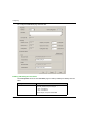
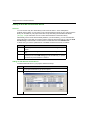
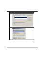
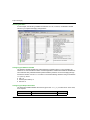
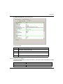
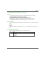
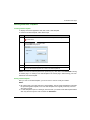
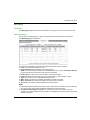
Description
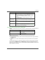
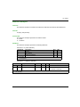
Use the Channel Properties page to:
select the IP address to use for:
connecting module or device DTMs to physical devices, and
sending explicit messages to Modbus TCP and EtherNet/IP devices
view your PC’s IP address settings
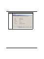
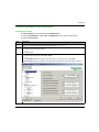
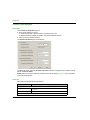
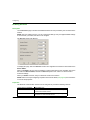
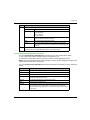
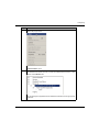
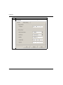
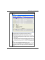
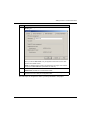
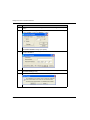
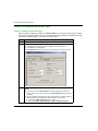
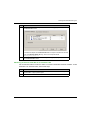
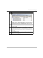
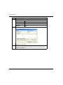
The Channel Properties page looks like this:
To display this page, select the Channel Properties node in the navigation tree located on the left
side of the Device Editor.
NOTE: Refer to the topic Configuring Properties in the Device Editor (see page 53) for instructions
on how to edit properties.
Properties
This page presents the following properties:
Name
Description
Source Address area:
Source IP Address:
A list of IP addresses assigned to network interface cards installed
on your PC.
Sub-Network Mask:
The subnet mask associated with the selected Source IP Address.
EtherNet/IP Network Detection area:
58
S1A34003 10/2014
Configuring
Name
Description
Begin detection
range address
The starting IP address of the address range for automatic field bus
discovery of EtherNet/IP devices.
End detection
range address
The ending IP address of the address range for automatic field bus
discovery of EtherNet/IP devices.
Modbus TCP Network Detection area:
Begin detection
range address
The starting IP address of the address range for automatic field bus
discovery of Modbus TCP devices.
End detection
range address
The ending IP address of the address range for automatic field bus
discovery of Modbus TCP devices.
S1A34003 10/2014
59
Configuring
Channel Properties - Ethernet Page
Description
Use the Ethernet page to:
view and edit the Connection Speed, which includes both the:
transmission speed, and
duplex mode
view the Frame Format
The Ethernet page looks like this:
To display this page, select the Channel Properties →Ethernet node in the navigation tree
located on the left side of the Device Editor.
NOTE: Refer to the topic Configuring Properties in the Device Editor (see page 53) for instructions
on how to edit properties.
Properties
This page presents the following properties:
Name
Description
Connection Speed
The transmission speed and duplex mode for the network. Values
include:
Auto 10/100 Mb (default)
100 Mb Half
100 Mb Full
10 Mb Half
10 Mb Full
NOTE: Schneider Electric recommends the default setting—Auto
10/100 Mb. This setting causes the connected devices to perform
auto-negotiation and thereby determine the fastest common
transmission rate and duplex mode.
Frame Format
60
Ethernet II is the only available value (read-only).
S1A34003 10/2014
Configuring
Channel Properties - TCP/IP Page
Description
Use the TCP/IP page to:
select a Configuration mode, which specifies how the communication module obtains its IP
addressing settings, and
edit the IP addressing settings that will be used if the Configuration mode is set to Static
The TCP/IP page looks like this:
To display this page, select the Channel Properties →TCP/IP node in the navigation tree located
on the left side of the Device Editor.
NOTE: Refer to the topic Configuring Properties in the Device Editor (see page 53) for instructions
on how to edit properties.
Selecting a Configuration Mode
Use the Configuration list to specify a configuration mode. The configuration mode setting
determines how the communication module obtains its IP address at startup. Choices are:
Configuration Mode
Description
Static
The module uses the scanner IP address, gateway IP address,
and sub-network mask configured in this page.
Flash Memory
The module uses the IP address configured via the TCP/IP object
and stored flash memory. An IP address configured by this
process survives both a warm and a cold re-start.
BOOTP
The module uses an IP address assigned by a BOOTP server.
S1A34003 10/2014
61
Configuring
Setting the Module Addresses in Static Mode
Three IP address properties need to be configured for the Ethernet communication module in
Static configuration mode:
Property
Description
Scanner IP Address
The 32-bit identifier—consisting of both a network address and a
host address—assigned to a device connected to a TCP/IP
Internet network using the Internet Protocol (IP).
Sub-Network Mask
The 32-bit value used to hide (or mask) the network portion of the
IP address and thereby reveal the host address of a device on a
network using the IP protocol.
Gateway Address
The address of a device, if any, that serves as a gateway to the
communication module.
Default Address Configurations
The communication module uses a default address configuration when it is not configured or when
a duplicate IP address is detected. The default address is based on the MAC address of the
module and makes it possible for several Schneider Electric devices to use their default network
configuration on the same network.
The module uses the following default address configurations:
Default IP Address
This default address starts with 10.10 and uses the last two bytes of the MAC address. As an
example, a device with the MAC address of 00:00:54:10:8A:05 has a default IP address of
10.10.138.5 (0x8A=138, 0x05=5).
Default Sub-Network Mask
The default address is 255.0.0.0 (a class A mask).
Default Gateway Address
The default gateway address is identical to the default IP address.
Duplicate Address Checking
Before going online, the module sends out at least four ARP (Address Resolution Protocol)
messages with a proposed IP address:
if an answer is returned:
another network device is already using the proposed IP address
the module will not use the proposed IP address, but will instead use the default IP address
if an answer is not returned:
the module is assigned the proposed IP address (along with the associated network
parameters.)
NOTE: When powering up an entire network, some switches may be slow to complete the power
up process. THis slow switch responce can cause some ARP messages to be dropped. To help
improve performance when powering up an entire network, confirm that the network switches
complete their power up cycle before powering up the PLCs.
62
S1A34003 10/2014
Configuring
Channel Properties - EtherNet/IP Page
Description
The EtherNet/IP page is displayed only when Unity Pro is operating in Advanced Mode
(see page 46). Advanced mode properties are identified by the
icon.
Use the EtherNet/IP page to configure the following communication module properties:
properties that determine how the communication module, as a scanner, opens connections for
both implicit and explicit messages
the frequency for transmitting produced data over implicit messaging connections
the timeout period for explicit messaging connections
the behavior of the communication module—as a scanner—when:
the application is stopped, or
the communication module receives a reset service request
The EtherNet/IP page looks like this:
To display this page, select the Channel Properties →EtherNet/IP node in the navigation tree
located on the left side of the Device Editor.
NOTE: Refer to the topic Configuring Properties in the Device Editor (see page 53) for instructions
on how to edit properties.
S1A34003 10/2014
63
Configuring
Properties
Note: Users experienced in the configuration of EtherNet/IP networks can edit the following readwrite properties.
Name
Description
Timeout
FW_Open IO Connection Timing
The amount of time the communication module waits for the
Forward_Open IO messaging transaction to open an implicit
messaging connection. Default = 5000 ms
FW_Open EM Connection Timing
The amount of time the communication module waits for the
Forward_Open IO messaging transaction to open an explicit
messaging connection. Default = 3000 ms
EM Connected RPI
The value used to set the T->O (target to originator) and O->T
(originator to target) requested packet interval (RPI) for explicit
message connections. This value is used to calculate the lifetime
of a connection. Default = 10000 ms.
EM Request Timeout
The amount of time the communication module waits between a
request and reply of an explicit message. Default =10 s.
Output
64
Allow reset explicit message
The behavior of the communication module—as scanner—when
it receives a reset service request:
TRUE indicates the module will accept the request and reset
itself.
FALSE indicates the module ignores the reset service request
and continues uninterrupted operations.
Default = FALSE
Behavior when CPU state is STOP
The state of the communication module when the CPU
application goes into a STOP state:
TRUE indicates that the module enters STOP state (implicit
connections are closed).
FALSE indicates that the module enters IDLE state (implicit
connections are not closed).
Default = FALSE
S1A34003 10/2014
Configuring
Section 2.5
Ethernet Services
Ethernet Services
Overview
This section describes how to enable and configure Ethernet services provided by the
TSX ETC 101 communication module.
What Is in This Section?
This section contains the following topics:
Topic
Page
Enabling Services
66
Configuring Access Control
68
Configuring the DHCP and FDR Servers
71
Configuring QoS Ethernet Packet Tagging
78
Configuring the Email Service
82
Sending Email via the SEND_REQ Block
85
Configuring the Network Time Service
88
Configuring the SNMP Agent
91
S1A34003 10/2014
65
Configuring
Enabling Services
Description
Use the Services page to enable and disable Ethernet services provided by the communications
module.
NOTE: After you enable a service, you can configure its settings. Unity Pro applies default settings
to each service you enable, but elect not to configure.
The Services page looks like this:
To display this page, select the Services node in the navigation tree located on the left side of the
Device Editor.
When you Enable a service, Unity Pro displays a node for that service in the navigation tree on the
left side of the Device Editor, beneath the Services parent node. Click on a service node to
access its settings.
When you Disable a service, Unity Pro hides the node for that service.
NOTE: Refer to the topic Configuring Properties in the Device Editor (see page 53) for instructions
on how to edit properties.
Properties
The Ethernet communication module can be configured to provide the following services:
66
If this service is enabled...
The module can...
Access Control
deny access to the Ethernet communication module by
unauthorized network devices.
Address Server
provide both IP addressing parameters and operating
parameters to other Ethernet devices.
S1A34003 10/2014
Configuring
If this service is enabled...
The module can...
Email
enable the sending—but not receiving—of email messages
from the PLC application to a standard SMTP server.
I/O Communication Control
allow the Unity Pro application to control the enabling and
disabling of individual connections between the
communication module and remote I/O devices.
NOTE:
The application can open and close individual
connections using the control bits located at the
beginning of the output area.
If this service is disabled the user—via the application
program—cannot toggle on and off connection control
bits
Network Time Service
provide the source time synchronization signal for the PLC
controller, which manages an internal clock to maintain this
time.
QoS Tagging
add Differentiated Services Code Point (DSCP) tags to
Ethernet packets so that network switches can prioritize the
transmission and forwarding of Ethernet packets.
NOTE: Before enabling QoS tagging, confirm that the
devices connected to the Ethernet communication module
support QoS tagging.
SNMP
serve as an SNMP v1 agent
provide trap information to up to two devices configured
as SNMP managers.
NOTE: The SNMP service is enabled by default and cannot
be disabled.
S1A34003 10/2014
67
Configuring
Configuring Access Control
Description
Use the Access Control page to restrict access to the Ethernet communication module in its role
as either a Modbus TCP or EtherNet/IP server. When access control is enabled in the Services
page, add the IP addresses of the following devices to the list of Authorized Addresses to permit
communication with that device:
the Ethernet communication module itself, so that the module can use EtherNet/IP explicit
messaging for any of the following purposes:
obtaining diagnostic data
resetting the module
changing the IP address
any client device that may send a request to the Ethernet communication module, in its role as
either Modbus TCP or EtherNet/IP server
your own maintenance PC, so that you can communicate with the PLC via Unity Pro to configure
and diagnose your application, and to view the module’s web pages
any target device to which the Ethernet communication module may send a Modbus TCP
explicit message
NOTE: You need not add to list the IP address of devices that will be the target of EtherNet/IP
explicit messages.
When access control is disabled in the Services page, the Ethernet communication module will
accept Modbus TCP and EtherNet/IP requests from any device.
68
S1A34003 10/2014
Configuring
The following graphic depicts the Access Control page immediately after a new row has been
added to the list of Authorized Addresses, but before the new item has been configured:
To display this page:
Step
Description
1
Select the Services node in the navigation tree located on the left side of the
Device Editor. The Services page opens.
2
In the Services page, set the Access Control field to Enabled and click either
OK or Apply. The Access Control node appears in the navigation tree.
3
Select the Access Control node in the navigation tree.
NOTE: Refer to the topic Configuring Properties in the Device Editor (see page 53) for instructions
on how to edit properties.
S1A34003 10/2014
69
Configuring
Adding and Removing Devices in the Authorized Address List
To add a device to the Authorized Addresses list:
Step
Description
1
In the Access Control page, click Add.
A new row appears in the Authorized Addresses list, displaying:
a red exclamation point, indicating editing has begun, and
a placeholder IP address of 0.0.0.0
2
Double-click the left mouse button on the placeholder IP address.
The IP address field expands and becomes editable.
3
In the new IP address field, type in the IP address of the device which will be able
to access the communication module, then press Enter.
4
Repeat steps 1 through 3, above, for each additional device to which you want
to grant access to the communication module.
5
Refer to the topic Configuring Properties in the Device Editor (see page 53) for
instructions on how to save your configuration edits.
To remove a device from the Authorized Addresses list, select its IP address in the list, then click
Remove. The selected IP address is removed.
70
S1A34003 10/2014
Configuring
Configuring the DHCP and FDR Servers
Description
The Ethernet communication module includes both a DHCP and a Faulty Device Replacement
(FDR) server. The DHCP server provides IP address settings to networked Ethernet devices. The
FDR server that provides operating parameter settings to replacement Ethernet devices that are
equipped with FDR client functionality.
Use the Address Server page to:
enable and disable the communication module’s FDR service
view an automatically generated list of devices included in the communication module’s
Ethernet configuration, displaying for each device:
IP addressing parameters, and
whether the device’s IP addressing parameters are provided by the communication module’s
embedded DHCP server
manually add remote devices—that are not part of the communication module’s Ethernet
configuration—to the communication module’s DHCP client list
NOTE: Confirm that each device you manually add is equipped with DHCP client software, and
is configured to subscribe to the communication module’s IP addressing service.
The Address Server page looks like this:
S1A34003 10/2014
71
Configuring
To display this page:
Step
Description
1
Select the Services node in the navigation tree located on the left side of the
Device Editor. The Services page opens.
2
In the Services page, set the Address Server field to Enabled. The Address
Server node appears in the navigation tree.
3
Select the Address Server node in the navigation tree.
Enabling the FDR Service
To enable the communication module’s FDR service, set the FDR Server field to Enabled. To
disable the service, toggle the same field to Disabled.
NOTE: Refer to the topic Configuring Properties in the Device Editor (see page 51) for instructions
on how to apply edited properties to networked devices.
Any networked Ethernet device equipped with FDR client software can subscribe to the
communication module’s FDR service. The communication module can store up to 1 MB of FDR
client operating parameter files. When this file storage capacity is reached, the module can not
store any additional client FDR files.
The communication module can store FDR client files for up to 128 devices, depending on the size
of each stored file. For example, if the size of each FDR client file is small—not more than 8 Kb—
the module could store up to the maximum of 128 parameter files.
Manually Adding Remote Devices to the DHCP Service
Remote devices that are part of the communication module’s Ethernet configuration—and which
have subscribed to the communication module’s DHCP IP addressing service—automatically
appear in the Automatically Added Devices list.
Other remote devices—that are not part of the communication module’s configuration—can be
manually added to the communication module’s DHCP IP addressing service.
To manually add networked Ethernet devices to the IP addressing service:
72
Step
Description
1
In the Address Server page, click the Add Device Manually button. Unity Pro adds
an empty row to the list of Manually Added Devices.
S1A34003 10/2014
Configuring
Step
Description
2
In the new row, configure the following parameters for the client device:
3
IP Address
Type in the IP address of the client device.
Identifier Type
Select the type of value the client device will use to identify itself
to the FDR server:
MAC address
Device Name
Identifier
Depending upon the identifier type, type in the client device
setting for the MAC address or Name.
Mask
Type in the client device subnet mask.
Gateway
Type in the gateway address used to access a remote client
device. Use 0.0.0.0 if the device is located on the same subnet as
the server.
Refer to the topic Configuring Properties in the Device Editor (see page 51) for
instructions on how to apply edited properties to networked devices.
Viewing the Auto-Generated DHCP Client List
The list of Automatically Added Devices includes a row for each remote device that is:
part of the communication module’s Ethernet configuration, and
configured to subscribe to the communication module’s DHCP addressing service
NOTE: You cannot add devices to this list in this page. Instead, use the configuration pages for the
remote device to subscribe to this service.
The list of Automatically Added Devices contains the following information for each networked
device:
Property
Description
Device Number
The number assigned to the device in the Unity Pro configuration.
IP Address
The client device IP address.
Enable DHCP
TRUE indicates that the device subscribes to the DHCP service.
Identifier Type
Indicates the mechanism used by the server to recognize the client (MAC
address or DHCP device name).
Identifier
The actual MAC address or DHCP device name.
Mask
The client device subnet mask.
Gateway
The IP address a DHCP client device will use to access other devices that
are not located on the local subnet. A value of 0.0.0.0 constrains the
DHCP client device by allowing it to communicate only with devices on the
local subnet.
S1A34003 10/2014
73
Configuring
Subscribing to the DHCP Service for a Device that is Part of the Configuration
An Ethernet device—that is part of the communication module Ethernet configuration—can
subscribe to the DHCP IP addressing service. To subscribe to the DHCP service for a specific
device, follow these steps:
Step
Action
1
In the DTM Browser, select the Ethernet communication module that is connected
to the remote device that you want to add to the DHCP service. In the following
example, the communication module with the alias name of ETC01 is selected:
NOTE: The selected module is connected to the STB NIC 2212 network interface
device bearing the alias name NIC2212_01, which is the module you want to add to
the DHCP service.
74
S1A34003 10/2014
Configuring
Step
Action
2
With ETC01 selected in the DTM Browser, click the right mouse button, and select
Open in the pop-up menu.:
The Device Editor opens.
3
In the navigation tree on the left side of the Device Editor, expand the Device List
node and select the device for which you want to enable the DHCP service. In this
example, select NIC2212_01:
Unity Pro displays the properties for the selected remote device in the right pane of
the window.
S1A34003 10/2014
75
Configuring
76
Step
Action
4
In the right pane of the window, select the Address Setting tab to display the
following page:
S1A34003 10/2014
Configuring
Step
Action
5
In the Address Server area of this page, configure the following properties:
DHCP for this device
Identified by
Select Enabled
The choices are:
MAC Address, or
Device Name
Select Device Name.
6
Identifier
Unity Pro has automatically added the device name
NIC2212_01. For the purpose of this example, accept
the default value.
Subnet Mask
Unity Pro has automatically applied the same subnet
mask used for the Ethernet communication module.
For the purpose of this example, accept the default
value of 255.255.255.0.
Gateway
Unity Pro has automatically applied the same
gateway used for the Ethernet communication
module. For the purpose of this example, accept the
default value of 0.0.0.0.
Click OK to save your edits.
NOTE: Refer to the topic Configuring Properties in the Device Editor (see page 51)
for more information on editing and saving property settings in this window.
S1A34003 10/2014
77
Configuring
Configuring QoS Ethernet Packet Tagging
Description
The Ethernet communication module can be configured to perform Ethernet packet tagging. The
module supports the OSI layer 3 Quality of Service (QoS) standard defined in RFC-2475. When
you enable QoS, the module adds a differentiated services code point (DSCP) tag to each Ethernet
packet it transmits, thereby indicating the priority of that packet.
Use the QoS page to:
specify the source of QoS packet priority settings, and
view or edit QoS DSCP prioritization values
The contents of the QoS page depends on the Ethernet communication module you selected for
your project: TSX ETC 101 or TSX ETC 101.2.
The QoS page displays five EtherNet/IP traffic types when you are operating in Advanced Mode
(see page 46) (see below), or two EtherNet/IP traffic types when Advanced Mode is de-selected.
To display this page:
Step
Description
1
Select the Services node in the navigation tree located on the left side of the
Device Editor. The Services page opens.
2
In the Services page, set the QoS Tagging field to Enabled, then click OK or
Apply. The QoS node appears in the navigation tree.
3
Select the QoS node in the navigation tree.
NOTE: Refer to the topic Configuring Properties in the Device Editor (see page 53) for instructions
on how to edit properties.
78
S1A34003 10/2014
Configuring
The QoS Page for the TSX ETC 101.2 Ethernet Communication Module
The following QoS page displays the default values for the TSX ETC 101.2 module displays when
operating in Advanced Mode:
S1A34003 10/2014
79
Configuring
The QoS Page for the TSX ETC 101 Ethernet Communication Module
The following QoS page displays the default values for the TSX ETC 101 module displays when
operating in Advanced Mode:
Specifying the Source of QoS Settings
The five QoS prioritization values can be set either from the communication module’s flash
memory, or in this page. To specify the QoS configuration source, set the Use value from field to
either:
Setting
Description
Configuration1
The communication module uses the settings input in the Type of Traffic
section of this page.
Flash1
The communication module uses the settings saved in the module’s flash
memory. The fields in the Type of Traffic section are read-only.
1. Schneider Electric recommends that QoS values be set in the configuration, and not by
saving settings to flash memory. Settings saved to flash memory will be lost if the module is
replaced.
NOTE: You can also edit QoS configuration settings by using explicit messages to set the
attributes of the QoS CIP object (see page 241).
80
S1A34003 10/2014
Configuring
Type of Traffic Settings
QoS tagging lets you prioritize Ethernet packet streams based on the type of traffic in that stream.
The communication module recognizes the traffic types described below. When the Use value
from field is set to Configuration, you can edit the prioritization values in this page. Each traffic
type can have a prioritization value from 0... 63.
Traffic Type
Default
DSCP Value for IO Data Scheduled Priority Messages (EtherNet/IP)
47
DSCP Value for Explicit Message (Modbus TCP & EtherNet/IP)
27
DSCP Value for IO Data Urgent Priority Messages (EtherNet/IP)1
55
DSCP Value for IO Data High Priority Messages (Modbus TCP & EtherNet/IP)1 43
DSCP Value for IO Data Low Priority Messages (EtherNet/IP)1
31
DSCP Value for Network Time Protocol Messages
59
1. Visible only when Advanced Mode (see page 46) is enabled.
To effectively implement QoS settings in your Ethernet network:
use network switches that support QoS
consistently apply DSCP values to network devices and switches that support DSCP
verify that switches apply a consistent set of rules for sorting DSCP tags, when transmitting and
receiving Ethernet packets
NOTE: The QoS settings for Scheduled, High, and Low priority messages also apply to input and
output priority messages for a remote device. You can configure these settings for a remote device
(see page 134) in the Device Editor by selecting a device connection node, then opening the
connection’s General page.
S1A34003 10/2014
81
Configuring
Configuring the Email Service
Using the Email Service
Use the Simple Mail Transfer Protocol (SMTP) service to configure up to three (3) Email
messages. The PLC uses the Email messages you configure to notify specified Email recipients
about meaningful run-time events—for example, a change in the value of a variable, or a threshold
overrun.
NOTE: The Email service is available only when you first perform the following tasks:
upgrade the firmware in the TSX ETC 101 Ethernet communication module to version 2.01 or
higher
select the TSX ETC 101.2 Ethernet communication module for your project using Unity Pro
version 7.0 or higher
Email messages are transmitted by the execution of a SEND_REQ (see page 85) function block
included in your application logic.
NOTE: To successfully send an Email message using the SEND_REQ block, synchronize the
SMTP service and PLC application—i.e., activate the SMTP service whenever the PLC is in RUN
mode.
You can configure the Email service only in the Email Configuration page of Unity Pro. You can
diagnose the operation of the Email service in the diagnostic pages of both the Unity Pro software
(see page 331) and the communication module web pages (see page 398).
82
S1A34003 10/2014
Configuring
Configuring Email Service Parameters
Use the following page to configure up to three Email messages:
To display this page:
Step
Description
1
Select the Services node in the navigation tree located on the left side of the
Device Editor. The Services page opens.
2
In the Services page, set the Email field to Enabled. The Email node appears
in the navigation tree.
3
Select the Email node in the navigation tree.
S1A34003 10/2014
83
Configuring
Viewing and Configuring Email Settings
The configurable Email service parameters include the following:
Parameter
Description
SMTP Server Configuration:
SMTP Server IP Address: The IP address of the SMTP server that will relay Email
messages.
SMTP Server Port:
TCP port used by the SMTP server. Default = 25.
Password Authentication:
Authentication:
Is client authentication by the SMTP Email server:
Disabled (default)
Enabled
Login:
If the SMTP server is configured for client authentication, the
user name, up to 64 characters.
Password:
If the SMTP server is configured for client authentication, the
client password string, up to 64 characters.
Email Header 1...3:
84
From:
The Email address of the sender, up to 64 characters.
To:
The Email addresses of the targeted recipients, up to 128
characters.
Subject:
The static part of the Email message, up to 32 characters.
S1A34003 10/2014
Configuring
Sending Email via the SEND_REQ Block
Using SEND_REQ to Send Pre-configured Email Messages
Use the SEND_REQ block in your application to programmatically send any of three email
messages you previously configured in Unity Pro (see page 82).
NOTE: To successfully send an Email message using the SEND_REQ block, synchronize the
SMTP service and PLC application—i.e., activate the SMTP service whenever the PLC is in RUN
mode.
FBD Representation
Input Parameters
The following table describes the input parameters:
Parameter
Data type
Description
ADR
Array [0...5] of INT
The path to the destination device, which has an
addresses ending in SYS; for example,
rack.slot.channel.SYS.
Use the EF ADDR to convert from the string format
to the array of INT. For example, if the module is
configured at rack 0, slot 4, channel 0, use:
ADDR(‘0.4.0.SYS’).
CODE
INT
Use the request code 0x37 (write Object) to send
the SMTP request to the TSX ETC 101 Ethernet
communication module.
EMIS
Array [n...m] of INT
Character string to be sent. The maximum length
of data to send is 246 bytes. Refer to the following
description of the EMIS parameter structure.
S1A34003 10/2014
85
Configuring
The EMIS parameter contains the character string to be sent
EMIS Description
Value
Byte
Word
Category
0x96
0 (low byte)
0
Segment
0x15
1 (high byte)
Type
0
2 (low byte)
Reserved byte 1
0
3 (high byte)
Reserved byte 2
0
4 (low byt)e
Number of characters (n1)
starting with the following byte
(i.e. Mail header number)
n1
(must be ≤240)
5 (high byte)
Mail header number
1, 2, 3
6 (low byte
Number of characters (n2) to be
added to the email subject line
n2
(must be ≤(n1–2))
7 (high byte)
n2 characters added to email
<user defined>
8...245 (max)
subject line1
Body of email message1, 2
86
1
2
3
4...122 (max)
(= (n1–2)/2)
<user defined>
1
The following (n1– 2)/2 words (up to a maximum of 119)) contain the data in ASCII format
that will be copied into the email message. The first n2 characters are added to the
configured email subject and the rest are part of the email body:
2
Use the $N (or $n) two-character tag to insert a line break in the email text.
S1A34003 10/2014
Configuring
Input/Output Parameters
The following table describes the GEST management parameter, which is the only input/output
parameter:
Parameter
Data type
Description
GEST
Array [0...3] of INT
The management parameter, consisting
of 4 words.
The GEST management parameter presents the following structure:
Description
Word Order
MSB
LSB
System-managed
data
1
Exchange number
Activity bit—the first bit of the first
word. It indicates the execution
status of the communication:
1 = Email is being sent
0 = Email complete
2
Operation report
(see page 411)
Communication report
(see page 411)
3
Timeout
4
Length: the size of the data buffer.
User-managed
data
Output Parameters
The following table describes the RECP received data parameter, which is the only output
parameter:
Parameter
Data type
Description
RECP
Array [n...m] of INT
The request does not return data.
S1A34003 10/2014
87
Configuring
Configuring the Network Time Service
The Network Time Protocol Client
The Ethernet communication module includes a network time protocol (NTP) client. After you
enable the network time service, you can configure the it by:
identifying two external NTP servers—a primary server, and a secondary server—the Ethernet
communication module uses to synchronize its internal time setting
specifying the time zone location of the module
enabling the automatic adjustment of the module internal time setting for daylight saving time
changes
The Ethernet communication module sends its internal time setting to the PLC controller over the
shared backplane. The PLC manages an internal clock to maintain this time, and uses the time
setting to time-stamp system events and I/O data.
NOTE: The network time service is available only when you first perform the following tasks:
upgrade the firmware in the TSX ETC 101 Ethernet communication module to version 2.01 or
higher
select the TSX ETC 101.2 Ethernet communication module for your project using Unity Pro
version 7.0 or higher
Operation of the network time service can be monitored and diagnosed in:
the Network Time Service Diagnostics page of the Unity Pro software (see page 333), and
the Network Time Service Diagnostics web page (see page 401)
You can configure the network time service only in the following page:
88
S1A34003 10/2014
Configuring
To display this page:
Step
Description
1
Select the Services node in the navigation tree located on the left side of the
Device Editor. The Services page opens.
2
In the Services page, set the Network Time Service field to Enabled. The
Network Time Service node appears in the navigation tree.
3
Select the Network Time Service node in the navigation tree.
Viewing and Configuring Network Time Service Settings
The following settings can be viewed and edited in this page:
Property
Description
NTP Server Configuration:
Primary NTP Server
IP Address
The IP address of the NTP server, from which the Ethernet
communication module first requests a time setting.
Secondary NTP Server
IP Address
The IP address of the back-up NTP server, from which the
Ethernet communication module requests a time setting, after
not receiving a response from the primary NTP server.
Polling Period
The frequency (1...120 seconds) the Ethernet communication
module uses for requesting a time setting from the NTP server.
Default = 18 seconds.
Time Zone:
Time Zone Setting
The time zone associated with the Ethernet communication
module, selected from a list that includes time zones around the
globe. Default = Greenwich Mean Time (GMT) + 0 minutes.
Timezone Offset
The number of minutes (–1439...+1439) used to adjust the Time
Zone Setting. Default = 0 minutes.
Daylight Saving:
Automatically adjust
clock for daylight saving
Enabled: turns ON the automatic clock adjustment for daylight
savings.
Disabled: turns OFF the automatic clock adjustment for
daylight savings.
Default = Disabled.
If automatic adjustment of the clock for daylight savings is
enabled, use the next two fields to configure daylight saving
adjustments.
S1A34003 10/2014
89
Configuring
Property
Description
Start Daylight Saving
Month
Select the month daylight savings begins.
Default = March.
Day of Week
Select the day of the week daylight savings
begins. Default = Sunday.
Week#
Select the week of the month that daylight
savings begins. Default = 1 (first week of the
month).
Month
Select the month daylight savings ends.
Default = November.
Day of Week
Select the day of the week daylight savings
ends. Default = Sunday.
Week#
Select the week of the month that daylight
savings ends. Default = 1 (first week of the
month).
End Daylight Saving
90
S1A34003 10/2014
Configuring
Configuring the SNMP Agent
Description
The Ethernet communication module includes an SNMP v1 agent. An SNMP agent is a software
component running on the communication module that allows access to the module’s diagnostic
and management information via the SNMP service.
SNMP browsers, network management software, and other tools typically use SNMP to access
this data. In addition, the SNMP agent can be configured with the IP address of up to two devices—
typically PC’s running network management software—to be the target of event driven trap
messages. These trap messages inform the management device of events such as cold start, and
detected authentication failures.
Use the SNMP page to configure the SNMP agent in the communication module. The SNMP agent
can connect to and communicate with up to 2 SNMP managers as part of an SNMP service. The
SNMP service includes:
authentication checking, by the Ethernet communication module, of any SNMP manager that
sends SNMP requests
management of event, or trap, reporting by the module
The SNMP page looks like this:
S1A34003 10/2014
91
Configuring
To display this page:
Step
Description
1
Select the Services node in the navigation tree located on the left side of the
Device Editor. The Services page opens.
2
In the Services page, set the SNMP field to Enabled, then click either OK or
Apply. The SNMP node appears in the navigation tree.
3
Select the SNMP node in the navigation tree.
NOTE: Refer to the topic Configuring Properties in the Device Editor (see page 53) for instructions
on how to edit properties.
Viewing and Configuring SNMP Properties
NOTE: The sysName SNMP parameter is neither editable nor visible in the Unity Pro Ethernet
Configuration Tool software. By default, the sysName is set to the Ethernet communication module
part number.
The following properties can be viewed and edited in the SNMP page:
Property
Description
IP Address Managers:
IP Address Manager 1
The IP address of the first SNMP manager to which the
SNMP agent sends notices of traps.
IP Address Manager 2
The IP address of the second SNMP manager to which
the SNMP agent sends notices of traps.
Agent:
Location
The device location (32 characters maximum)
Contact
Information describing the person to contact for device
maintenance (32 characters maximum)
SNMP Manager
Select either:
TRUE: the Location and Contact information are
editable in this page
FALSE: Location and Contact settings are not editable
in this page
Community Names:
92
Get
Password required by the SNMP agent before executing
read commands from an SNMP manager.
Default = public.
Set
Password required by the SNMP agent before executing
write commands from an SNMP manager.
Default = public
S1A34003 10/2014
Configuring
Property
Description
Trap
Password an SNMP manager requires from the SNMP
agent before the manager will accept trap notices from the
agent. Default = public
Security:
Enable Authentication Failure
Trap
S1A34003 10/2014
TRUE causes the SNMP agent to send a trap notification
message to the SNMP manager if an unauthorized
manager sends a Get or Set command to the agent.
Default = FALSE.
93
Configuring
Section 2.6
Security
Security
Security Features
Security and HTTP, FTP, and TFTP Services
You can enhance security for your project by disabling the FTP/TFTP and HTTP services at times
when you do not need to use them. The module uses the HTTP service to provide access to the
embedded webpages. The module uses the FTP and TFTP services to support various features
including firmware upgrades, and FDR services.
The module’s HTTP, FTP, and TFTP services can be disabled or enabled using the DTM Browser
Security screen.
HTTP, FTP, and TFTP services are disabled by default in DTM instances created using
TSX ETC 101 module firmware version 2.04 or later and Unity Pro 8.1 or later. They are enabled
by default in instances created using previous versions of Unity Pro.
You can use Unity Pro to enable or disable HTTP, FTP, and TFTP services as described in the
following procedure.
If the HTTP, FTP, or TFTP services have been enabled with Unity Pro, they can also be enabled
or disabled at run time using a DATA_EXCH function block. (See the Communication Block Library
for Unity Pro.)
Using Unity Pro to Enable and Disable Firmware Upgrade & FDR and Web Access Services
Perform the following steps to enable or disable FTP/TFTP or HTTP services on the module.
Step
94
Action
1
In the Unity Pro main menu, select Tools →DTM Browser to open the
DTM Browser.
2
Confirm that the DTM you want to use is not connected to the actual
communication module or device. If necessary, disconnect the DTM from the
module or device (see page 42).
3
In the DTM Browser, select the module. Right-click and select Open to open
the Device Editor.
4
Click the Security node in the navigation tree in the left panel to open the
Security screen.
5
On the Security screen, choose the appropriate setting: (Enabled or Disabled)
for the service or services.
S1A34003 10/2014
Configuring
Step
6
Action
Click:
Apply to save the changes and keep the window
- or OK to save the changes and close the window
The edits do not take effect until they are successfully downloaded from your PC to the CPU and
from the CPU to the communication modules and network devices.
S1A34003 10/2014
95
Configuring
Section 2.7
Configuring the Ethernet Communication Module as an EtherNet/IP Adapter
Configuring the Ethernet Communication Module as an
EtherNet/IP Adapter
Overview
This section describes how to configure the Ethernet communication module to act as an
EtherNet/IP adapter, using a functionality called Local Slave. The communication module supports
up to three instances of local slaves.
In its role as a EtherNet/IP adapter, the module initiates no messages. Instead, it responds to:
implicit messaging requests from a scanner device in the network, and
explicit messaging requests—directed to the communication module’s assembly object
(see page 235)—from other devices on the network
NOTE: If no local slave instance is enabled, the communication module can respond to explicit
messaging requests directed at its CIP objects (see page 231) other than the assembly object.
What Is in This Section?
This section contains the following topics:
Topic
Introducing the Local Slave
97
Configuring a Local Slave
99
Local Slave Inputs and Outputs
96
Page
104
S1A34003 10/2014
Configuring
Introducing the Local Slave
Local Slave Networking Example
The Ethernet communication module supports up to three instances of the local slave functionality.
The local slave functionality allows other scanners on the network to read from, and write to, the
Ethernet communication module using implicit messaging. Each local slave instance can accept
one exclusive owner connection and one listen only connection. Through a local slave, a remote
scanner can access the communication module’s CIP Assembly object (see page 235). The local
slave function is especially beneficial for peer to peer data exchanges at a repetitive rate.
NOTE:
The Ethernet communication module can provide three local slave adapter instances, while
simultaneously performing as a scanner. These roles are not mutually exclusive.
The local slave is exclusively an EtherNet/IP functionality.
The sample configuration, above, includes the following scanners and adapters:
A primary PLC (1) with one local slave instance enabled. The PLC performs the following
functions:
scans I/O data from remote devices (4 and 5)
scans input data from its own local slave instance
A third party scanner (6)—which lacks adapter capability, and therefore cannot itself be scanned
by the primary PLC (1)—performs the following functions:
S1A34003 10/2014
97
Configuring
collects data from other sources (not part of this network)
writes data to inputs of the primary PLC’s local slave
scans the primary PLC’s local slave’s output data via an exclusive owner connection
A secondary scanner (7), which also scans the primary PLC’s local slave—for the very same
output data scanned by the third party scanner—via a listen only connection
NOTE:
Because the third party scanner (6) and the secondary scanner (8) both receive the same data
produced by the local slave, the requested packet interval (RPI) settings of the third party
scanner’s exclusive owner connection are the same as those of the secondary scanner’s listen
only connection.
By enabling a local slave on the primary PLC (1):
PLC (1) allows the third party PLC (6) to write to it at a repetitive rate, even if PLC (6) is not
capable of acting as an adapter.
the secondary PLC (7) is able to scan the primary PLC (1) at a repetitive rate, rather than
through application intensive explicit messaging.
The topics in this section show you how to use Unity Pro software installed in the PC (2, above) to
configure a local slave, and to create input and output items in support of the peer-to-peer data
transfers between and among scanners.
98
S1A34003 10/2014
Configuring
Configuring a Local Slave
Description
The Ethernet communication module presents three identical Local Slave configuration pages.
Use each pages to configure a separate local slave instance. Create a local slave instance by:
enabling and naming each local slave
specifying the size of local slave input and output assemblies
configuring local slave variable names
To display this page, select one of the three Local Slave nodes in the navigation tree located on
the left side of the Device Editor.
NOTE: Refer to the topic Configuring Properties in the Device Editor (see page 51) for instructions
on how to edit properties.
The following steps describe a sample configuration for Local Slave 1. Your configuration may be
different.
Configuration Example: Local Slave 1
In the sample network configuration (see page 97), the application in the third-party PLC produces
data, which is available in the PLC’s Ethernet communication module as inputs. In this example,
the third-party device produces the following information:
production totals for manufacturing line A
production totals for manufacturing line B
the number of production interruption events for line A
the number of production interruption events for line B
Any information that needs to be passed to the third-party device—for example, confirmation that
data from the third-party device has been received by the PLC—is accessible in the third-party
device as input data. In this example, the third-party device is programmed to scan Local Slave 1
for this confirmation.
When configuring inputs and outputs in both the local slave and the third-party PLC, associate
inputs and outputs as follows:
Associate these local slave items:
With these third-party PLC items:
Outputs (T to O)—assembly instance 101
Inputs—assembly instance 101
Inputs (O to T)—assembly instance 102
Outputs—assembly instance 102
S1A34003 10/2014
99
Configuring
The configured Local Slave page looks like this:
Enabling and Naming the Local Slave
Use the Properties section of the Local Slave page to enable (or disable) and identify the local
slave.
Setting
Description
Number
The unique number—or identifier—assigned to the
device. By default, Unity Pro assigns:
000 = local slave 1
001 = local slave 2
002 = local slave 3
In this example, accept the default 000.
100
S1A34003 10/2014
Configuring
Setting
Description
Active Configuration
Enabled activates the local slave.
Disabled de-activates the local slave, but retains the
current local slave settings.
In this example, select Enabled.
Comment
An optional free text comment field up to 80 characters
maximum.
In this example, leave blank.
Connection bit
Auto-generated integer (0 to 127) indicating the offset of
the connection’s:
health bit, located in the input area
control bit, located in the output area
Note: This setting is auto-generated after the local slave
settings are entered and the network configuration is
saved.
Configuring the Size of Local Slave Input and Output Assemblies
Use the Assemblies section of the Local Slave page to configure the size of the local slave inputs
and outputs. The assembly numbers are non-editable, and are assigned by Unity Pro as follows:
Assembly number
Local slave number
Used for connection
101
1
T->O 1
102
1
O->T Exclusive Owner
103
1
Configuration
199
1
O->T Listen Only
111
2
T->O
112
2
O->T Exclusive Owner
113
2
Configuration
200
2
O->T Listen Only
121
3
T->O
122
3
O->T Exclusive Owner
123
3
Configuration
201
3
O->T Listen Only
1. In this table:
O indicates the originator—or scanner—device
T indicates the target—or adapter—device
S1A34003 10/2014
101
Configuring
The Local Slave assembly settings include:.
Setting
Description
Outputs (T->O)
A read-only value (see table, above).
In this example, 101.
Outputs (T->O) Size
The maximum size—in bytes—reserved for local slave outputs.
An integer from 1 to 509.
In this example, only two output bytes are used: type in 2.
Inputs (O->T)
A read-only value (see table, above).
In this example, 102.
Inputs (O->T) Size
The maximum size—in bytes—reserved for local slave inputs. An
integer from 0 to 509.
In this example, only eight input bytes are used: type in 8.
Configuration
A read-only value (see table, above).
In this example, 103.
Configuration Size
A read-only value set to 0.
NOTE: When using explicit messaging to read the Ethernet communication module’s assembly
object, allocate sufficient room for the response, because the size of the response will equal the
sum of:
NOTE:
the assembly size + Reply service (1 byte) + General Status (1 byte)
Configuring Local Slave I/O Variable Names
Each input and output that Unity Pro creates for your application has both a non-editable structure
name (used by Unity Pro to internally identify input and output items) and an editable variable
name.
Use the I/O Structure Name section of the Local Slave page to:
view and edit local slave input and output variable names
view non-editable local slave structure names
The following property settings have been made in this example:
Setting
Description
Input:
Structure Name
The read-only name for input structures. By default, it is the
concatenation of:
the prefix T_
the alias device name—in this case ETC01
the device number—in this case 01
the suffix _IN
In this case, the default would be T_ETC01_01_IN.
102
S1A34003 10/2014
Configuring
Setting
Description
Variable Name
The editable base name for input variables. By default, it is the
concatenation of:
the alias device name—in this case ETC01
the device number—in this case 01
the suffix _IN
In this case, the default would be ETC01_01_IN.
For this example, accept the default variable name.
Output:
Structure Name
The read-only name for output structures. By default, it is the
concatenation of:
the prefix T_
the alias device name—in this case ETC01
the device number—in this case 01
the suffix _OUT
Variable Name
The editable base name for output variables. By default, it is the
concatenation of:
the alias device name—in this case ETC01
the device number—in this case 01
the suffix _OUT
In this case, the default would be T_ETC01_01_OUT.
In this case, the default would be ETC01_01_OUT.
For this example, accept the default variable name.
If you have edited one or more variable names, you can restore the default variable names by
clicking on the Default Name button.
S1A34003 10/2014
103
Configuring
Local Slave Inputs and Outputs
Introduction
The Ethernet communication module serves as an adapter when the Active Configuration field
is set to Enabled in the configuration window for one (or more) of the module’s local slave nodes.
When a local slave instance of an Ethernet communication module is enabled, the designated
memory location allocated to that instance is exposed to, and can be accessed by, other devices.
The I/O data exchange, between the remote device and the local slave, is configured as part of the
remote device’s configuration settings.
Configuring the I/O Items
You can configure input and output items in groups of 1 or more single bits, 8-bit bytes, 16-bit
words, 32-bit dwords, or 32-bit IEEE floating values. The number of items you create depends
upon the data type and size of each item.
The process for creating and defining I/O items for the local slave is the same as for any adapter
class device, and depends upon the type of items you wish to create.
In support of the ongoing configuration example, the following items are required:
4 input word items
1 output word item
NOTE: The items created, below, are designed to hold data received from, or sent to, the thirdparty scanner. In addition to these items, it is necessary to include logic in the application programs
in which the Ethernet communication module and the third-party scanner, respectively, are
included. Writing this code is beyond the scope of this example.
104
S1A34003 10/2014
Configuring
Creating Input Word Items
To create input items for local slave 01:
Step
1
Action
Select the Input tab to open that page:
NOTE: In this example, each row represents a byte. Because the items you create
will be a 16-bit words, each item consists of 2 rows.
2
In the Default Item Name Root input box type: ProductionTotal_LineA.
3
Starting at the beginning of the table, select the first two rows: 0 and 1:
S1A34003 10/2014
105
Configuring
Step
106
Action
4
Click the Define Item(s) button.
Result: The Item Name Definition dialog opens:
5
Select WORD as the New Item(s) Data Type, then click OK.
Result: A new item is created:
6
Click Apply to save the new items, and leave the page open.
7
Repeat steps 2 - 6 for each new word item you need to create. In this example,
that includes the following items:
Rows 2-3, Default Items Name Root: ProductionTotal_LineB
Rows 4-5: Default Items Name Root: Events_LineA
Rows 6-7: Default Items Name Root: Events_LineB
8
Create output words.
S1A34003 10/2014
Configuring
Creating Output Word Items
To create output items for local slave 01:
Step
1
Action
Click the Output tab to open the following page:
NOTE: In this example, each row represents a byte. Because the only item you will
create is a 16-bit word, you will select 2 rows.
2
S1A34003 10/2014
In the Default Item Name Root input box type: DataReceived.
107
Configuring
Step
108
Action
3
Starting at the beginning of the table, select the first 2 rows, 0 and 1:
4
Click the Define Item(s) button.
Result: The Item Name Definition dialog opens:
S1A34003 10/2014
Configuring
Step
Action
5
Select WORD as the New Item(s) Data Type, then click OK.
Result: A new item is created:
6
Click OK to close the Items window.
7
Select File →Save to save your edits.
Using Local Slave Inputs and Outputs
The inputs and outputs created, above, are used as follows:
The third-party device updates values of the following variables:
ProductionTotal_LineA
ProductionTotal_LineB
Events_LineA
Events_LineB
The Ethernet communication module updates value of the DataReceived variable in the thirdparty device at the configured RPI.
S1A34003 10/2014
109
Configuring
110
S1A34003 10/2014
Premium
Adding Devices to an Ethernet Network
S1A34003 10/2014
Chapter 3
Adding Devices to an Ethernet Network
Adding Devices to an Ethernet Network
Overview
This chapter presents examples of how to add devices to, and how to configure these device for
operations on, your Ethernet network.
What Is in This Chapter?
This chapter contains the following sections:
Section
Topic
Page
3.1
Hardware Catalog
112
3.2
Adding an EtherNet/IP Device to the Network
121
3.3
Adding a Modbus TCP Device to the Network
157
S1A34003 10/2014
111
Adding Devices to an Ethernet Network
Section 3.1
Hardware Catalog
Hardware Catalog
Overview
Unity Pro includes a collection of modules and devices—called the Hardware Catalog—that you
can add to a Unity Pro project. EtherNet/IP and Modbus TCP devices are located in the hardware
catalog’s DTM Catalog page. Each device in the catalog is represented by a DTM that defines the
parameters of the module or device.
Not every device on the market today offer device-specific DTMs. Some devices are instead
defined by a device-specific EDS file. Unity Pro displays each EDS file in the form of a DTM. In this
way, you can use Unity Pro to configure these Ethernet/IP devices—defined by an EDS file—in the
same way you would configure a DTM-defined device.
Other devices lack both a DTM and an EDS file. You can configure these devices by using a
Generic DTM that is included in the DTM Catalog page.
This section address the topics:
how to add a DTM to the catalog
how to add an EDS file to the catalog
how to update the catalog
how to remove an EDS file from the catalog
What Is in This Section?
This section contains the following topics:
Topic
112
Page
Adding a DTM to the Unity Pro Hardware Catalog
113
Add an EDS File to the Unity Pro Hardware Catalog
114
Updating the Unity Pro Hardware Catalog
117
Remove an EDS File from the Unity Pro Hardware Catalog
119
S1A34003 10/2014
Adding Devices to an Ethernet Network
Adding a DTM to the Unity Pro Hardware Catalog
A Manufacturer Defined Process
Before a you can add a DTM to the Unity Pro Hardware Catalog, install it on the host PC—the
same PC that is running Unity Pro—by means of an installation process defined by the device
manufacturer.
Consult your device documentation, provided by the device manufacturer, for information
describing how to install a device DTM on your PC.
For instructions on how to install the TSX ETC 101 Ethernet communication module, refer to the
topic Installing Unity Pro Ethernet Configuration Tool Software (see page 21).
NOTE: After you successfully install a device DTM on your PC, update the Unity Pro
Hardware Catalog (see page 117) so the new DTM is visible in the catalog and available to be
added to a Unity Pro project.
S1A34003 10/2014
113
Adding Devices to an Ethernet Network
Add an EDS File to the Unity Pro Hardware Catalog
Overview
Unity Pro includes a wizard you can use to add one or more EDS files to the Unity Pro
Hardware Catalog. The wizard presents a series of instruction screens that:
simplify the process of adding EDS files to the catalog, and
provide a redundancy check in case you attempt to add duplicate EDS files to the catalog
NOTE: The Unity Pro Hardware Catalog displays a partial collection of DTMs and EDS files
registered with the ODVA. This library includes DTMs and EDS files for products not manufactured
or sold by Schneider Electric. The non-Schneider Electric EDS files are identified by vendor in the
catalog. Please contact the identified device’s manufacturer for inquiries regarding the
corresponding non-Schneider Electric EDS files.
Adding EDS Files
To add one or more EDS files to the library:
Step
114
Action
1
If the DTM Browser is not already open, in the Unity Pro main menu select Tools
→DTM Browser.
2
In the DTM Browser, select a communication module, then click the right mouse
button.
A pop-up menu opens.
3
In the pop-up menu, select Device menu →Add EDS to library.
The introductory page of the wizard opens.
S1A34003 10/2014
Adding Devices to an Ethernet Network
Step
Action
4
Click Next.
Page 2 of the wizard opens:
5
In the Select the Location of the EDS File(s) section, select either:
Add File(s), to add one or more EDS files you will individually select, or
Add all the EDS from the Directory, to add all files from a folder you will select.
Select Look in Subfolders to also add EDS files in subfolders beneath the
folder you selected.
6
Click the Browse button.
The Open dialog opens.
7
Use the Open dialog to navigate to and select:
one or more EDS files, or
a folder containing EDS files
8
After you have made your selections), click Open.
The dialog closes and your selection appears in the Directory or File Name field.
9
Click Next.
The wizard compares the selected EDS files against existing files in the library.
10
S1A34003 10/2014
(Conditional) If one or more selected EDS files is a duplicate, a File Already Exists
message opens.
Close the message.
115
Adding Devices to an Ethernet Network
Step
11
Action
Page 3 of the wizard opens indicating the Status of each device you attempted to
add:
a green check mark
indicates the EDS file can be added
a blue informational icon
a red exclamation point
indicates a redundant file
indicates an invalid EDS file
(Optional) Select a file in the list, then click View Selected File to open it.
116
12
Click Next to add the non-duplicate files.
Page 4 of the wizard opens, indicating the action is complete.
13
Click Finish to close the wizard.
14
The next step is to update the Unity Pro Hardware Catalog (see page 117), so that
the newly added device is available for inclusion in a Unity Pro project.
S1A34003 10/2014
Adding Devices to an Ethernet Network
Updating the Unity Pro Hardware Catalog
Updating Hardware Catalog
After you have followed the manufacturer’s instructions and installed a module or device DTM on
your PC, the next step is to update the Unity Pro Hardware Catalog. Updating the
Hardware Catalog makes the new Ethernet module or device available for addition to your Unity
Pro application.
To update the Hardware Catalog:
Step
Action
1
In the Unity Pro main menu, select Tools →Hardware Catalog. The
Hardware Catalog window opens.
2
In the Hardware Catalog window, select the DTM Catalog tab to display a module
and device DTM list. At the time of initial software installation, the catalog displays
no devices:
3
Click the External Update Tool button. The FDT/DTM Catalog window opens:
4
In the FDT/DTM Catalog window, click Update. The window refreshes itself, as
indicated by the progress bar in the lower right corner of the window.
S1A34003 10/2014
117
Adding Devices to an Ethernet Network
118
Step
Action
5
After the update has finished, click Close. The FDT/DTM Catalog window closes
and the Hardware Catalog displays.
6
In the Hardware Catalog window, click Reload catalog to refresh the DTM list.
S1A34003 10/2014
Adding Devices to an Ethernet Network
Remove an EDS File from the Unity Pro Hardware Catalog
Overview
You can remove a module or device from the list of available devices in the Unity Pro
Hardware Catalog by removing its EDS file. When you remove an EDS file from the library, the
device or module is no longer displayed by Unity Pro in the DTM Catalog page of the
Hardware Catalog window.
However, removing an EDS file from the library does not delete the file. Instead, the EDS file
remains in its stored location and can again be added to the catalog (see page 114) at a future
time.
Removing an EDS File from the Catalog
To remove an EDS file from the catalog:
Step
Action
1
If the DTM Browser is not already open, in the Unity Pro main menu select Tools
→DTM Browser.
2
In the DTM Browser, select a communication module, then click the right mouse
button.
A pop-up menu opens.
3
In the pop-up menu, select Device menu →Remove EDS from library.
The following window opens:
S1A34003 10/2014
119
Adding Devices to an Ethernet Network
Step
Action
4
Use the selection lists in the heading of this window to specify how EDS files will be
displayed:
Display
Sort by
Filters the list of displayed EDS files; select:
All EDS (no filtering)
Only Devices
Only Chassis
Only Modules
Sorts the list of displayed EDS files; select:
File Name
Manufacturer
Category
Device Name
Displayed Name
The description displayed for each device; select:
Catalog Name
Product Name
120
5
In the Device Library tree control, navigate to and select the EDS file you want to
remove.
6
(Optional) Click the View Selected File button to display the read-only contents of
the selected EDS file.
7
Click the Delete Selected File button. A message box opens.
8
Click Yes to remove the selected EDS file from the list.
9
When you have finished removing EDS files, click Close.
10
The next step is to update the Hardware Catalog (see page 117).
S1A34003 10/2014
Adding Devices to an Ethernet Network
Section 3.2
Adding an EtherNet/IP Device to the Network
Adding an EtherNet/IP Device to the Network
Overview
This section extends the sample Unity Pro application, by describing how to:
add an STB NIC 2212 EtherNet/IP network interface module to your Unity Pro application
configure the STB NIC 2212 module
configure EtherNet/IP connections linking the TSX ETC 101 communication module and the
STB NIC 2212 network interface module
configure I/O items for the Advantys Island
NOTE: The instructions in this chapter describe a single, specific device configuration example.
Refer to the Unity Pro help files for additional information about alternative configuration choices.
What Is in This Section?
This section contains the following topics:
Topic
Page
Setting Up Your Network
122
Adding an STB NIC 2212 Remote Device
124
Configuring STB NIC 2212 Properties
126
Configuring EtherNet/IP Connections
132
Connecting to the Advantys STB Island
138
Configuring I/O Items
142
S1A34003 10/2014
121
Adding Devices to an Ethernet Network
Setting Up Your Network
Overview
This sample network includes the following hardware and software:
a controller rack with:
TSX PSY 2600 M, 115/230 VAC power supply
TSX P57 4634, 14A controller
TSX ETC 101, Ethernet communication module
a remote STB Advantys island with:
STB NIC 2212 EtherNet/IP network interface module
STB PDT 3100 power distribution module
STB DDI 3230 2 pt digital input module
STB DDO 3200 2 pt digital output module
STB DDI 3420 4 pt digital input module
STB DDO 3410 4 pt digital output module
STB DDI 3610 6 pt digital input module
STB DDO 3600 6 pt digital output module
STB AVI 1270 2 pt analog input module
STB AVO 1250 2 pt analog output module
a PC running both Unity Pro (version 5.0 or higher) and Advantys configuration software
(version 5.0 or higher)
an Ethernet managed switch that is connected to the both the controller and island by means of
twisted pair Ethernet cable and RJ45 connectors.
122
S1A34003 10/2014
Adding Devices to an Ethernet Network
Network Topology
The Ethernet network devices used in this configuration include the following:
To re-create this example:
use the IP addresses for your own configuration’s:
PC
TSX ETC 101 Ethernet communication module
STB NIC 2212 network interface module
check wiring
NOTE: Unity Pro software running in the PC is used to configure the TSX P57 4634 controller. In
this example, the PC is indirectly wired to the CPU’s Ethernet port via the Ethernet switch.
Alternatively, you could bypass the switch and directly wire the PC to either the CPU’s Modbus or
USB ports.
S1A34003 10/2014
123
Adding Devices to an Ethernet Network
Adding an STB NIC 2212 Remote Device
Overview
You can use the Unity Pro device library to add a remote device—in this example the
STB NIC 2212 module—to your project. Only a remote device that is part of your Unity Pro device
library can be added to your project. Refer to the topic describing the Add EDS File Wizard
(see page 114) for instructions on how to add a device EDS file to the device library.
Alternatively, with a remote device already added to your device library, you can use automatic
device discovery to populate your project. Perform automatic device discovery by using the Field
bus discovery command with a communication module selected in the DTM Browser.
In either case, you need to update the list of available modules and devices, as follows:
Step
Action
1
In the Unity Pro main menu, select Tools →Hardware Catalog to display that
window.
2
In the Hardware Catalog window, click on the DTM Catalog tab to open that
page.
2
In the DTM Catalog page, click Reload catalog. The list of available devices,
as displayed both in the DTM Catalog page and the Add dialog, is updated
and reflects any device additions or deletions.
Adding an STB NIC 2212 Remote Device
To add the STB NIC 2212 to your project, follow these steps:
124
Step
Action
1
In the DTM Browser, select the Ethernet communication module node, and then
click the right mouse button. A pop-up menu opens.
2
In the pop-up menu, select Add... The following dialog opens:
S1A34003 10/2014
Adding Devices to an Ethernet Network
Step
Action
3
In the Add dialog, select the STBNIC2212, then click Add DTM. The Properties
window for the STB NIC 2212 network interface module opens.
4
In the General page of the Properties window, edit the default Alias name,
because retaining the original default name can result in duplicate module names.
In this example, type in the name NIC2212_01:
When you edit the Alias name, Unity Pro applies it as the base for both structure
and variable names.
NOTE: No additional editing needs to be performed in the pages of this window.
Except for the Alias name field, parameters are read-only.
5
Click OK. Unity Pro adds the new STB NIC 2212 network interface module to the
DTM Browser, beneath the communication module.
6
Refer to the topic Configuring Properties in the Device Editor (see page 53) for
instructions on how to save your configuration edits.
The next step is to configure the device you have just added to the project.
S1A34003 10/2014
125
Adding Devices to an Ethernet Network
Configuring STB NIC 2212 Properties
Overview
Use the pages of the Device Editor to view and edit settings for a remote device. Before you can
edit the device settings, disconnect the DTM from the remote device (see page 45).
To display the DTM settings for a remote device, select the device name, which is found under the
Device List node in the left pane of the Device Editor.
For the purposes of this example, which configures an STB NIC 2212 network interface module,
select the node named NIC2212 01. The Device Editor displays the following pages:
Properties
Address Setting
NOTE: Refer to the topic Configuring Properties in the Device Editor (see page 53) for instructions
on how to edit properties.
126
S1A34003 10/2014
Adding Devices to an Ethernet Network
Configuring the Properties Page
The Properties page for an STB NIC 2212 network interface module looks like this:
The following settings are used in this sample configuration. Use settings that are appropriate for
your actual application:
Step
Action
1
In the Properties section of the page, edit the following:
Number
The relative position of the device in the list, from 0 to 127.
For this example, accept the default of 003.
Active Configuration
Enabled: adds this device to the Unity Pro project
configuration
Disabled: removes this device from the Unity Pro
project configuration
Accept the default setting of Enabled.
S1A34003 10/2014
127
Adding Devices to an Ethernet Network
Step
Action
2
In the IO Structure Name section of the page, edit the following:
Input area:
Structure Name
(Read-only) Unity Pro automatically assigns a structure
name based on the variable name, in this case
T_NIC2212_01_IN.
Variable Name
Accept the auto-generated input variable name (based on
the alias name (see page 124)): NIC2212_01_IN.
Output area:
128
Structure Name
(Read-only) Unity Pro automatically assigns a structure
name based on the variable name, in this case
T_NIC2212_01_OUT.
Variable Name
Accept the auto-generated output variable name (based
on the alias name): NIC2212_01_OUT.
Default Name button
Restores the default variable and structure names. For this
example, custom names are used instead of the default
names.
S1A34003 10/2014
Adding Devices to an Ethernet Network
Step
Action
3
In the Items Management section of the page, edit the following:
Import mode
Automatic: Select this if I/O items are pre-defined for
the device in its DTM, and will not subsequently be
edited. These items are automatically created and
added to the configuration, and later updated if the
items list if the device DTM changes. These autocreated items cannot be edited in the Device Editor.
Manual: Select this if I/O items will be manually created
or edited. If the device DTM pre-defines I/O items,
those pre-defined I/O items are automatically created
and added to the configuration, and can later be
manually edited in the Device Editor. The I/O items list
is not affected by changes to the device DTM.
NOTE:
Because the STB NIC 2212 DTM does not contain pre-
configured input and output items, select Manual.
To view I/O items, navigate to and select the Items
node in the left pane of the Device Editor, as follows:
Reimport Items
4
S1A34003 10/2014
Imports the I/O items list from the device DTM, overwriting
any manual I/O item edits. Enabled only when Import
mode is set to Manual.
Click Apply to save your edits, and leave the window open for further edits.
129
Adding Devices to an Ethernet Network
Configuring the Address Setting Page
Use the Address Setting page to enable the DHCP client in the STB NIC 2212 network interface
module. When the DHCP client is enabled in the remote device, it will obtain its IP address from
the DHCP server in the Ethernet communication module. The Address Setting page looks like
this:
130
S1A34003 10/2014
Adding Devices to an Ethernet Network
The following settings are used in this sample configuration. Use settings that are appropriate for
your actual application:
Step
Action
1
In the Address Settings page, edit the following:
IP Address
By default:
the first three octet values equal the first three octet
values of the Ethernet communication module, and
the fourth octet value equals this device Number
setting—in this case, the default value would be 004.
In our continuing example, type in the address
192.168.1.6.
DHCP for this Device
Enabled activates the DHCP client in this device. The
device obtains its IP address from the DHCP service
provided by the Ethernet communication module and
appears on the auto-generated DHCP client list.
Disabled (the default) de-activates the DHCP client in
this device.
Select Enabled.
Identified by
If DHCP for this Device is Enabled, this indicates the
device identifier type:
MAC Address, or
Device Name
Select Device Name.
2
Identifier
If DHCP for this Device is Enabled, the specific device
MAC Address or Name value.
Accept the default setting of NIC2212_01 (based on the
Alias name).
Mask
The device subnet mask. The default = 255.255.255.0.
Accept the default value.
Gateway
The gateway address used to reach this device. The
default of 0.0.0.0 indicates this device is located on the
same subnet as the Ethernet communication module.
Accept the default value.
Click OK to save your edits.
The next step is to configure the connection between the communication module and the remote
device.
S1A34003 10/2014
131
Adding Devices to an Ethernet Network
Configuring EtherNet/IP Connections
Overview
An EtherNet/IP connection provides a communication link between two or more devices.
Properties for a single connection can be configured in the DTMs for the connected devices.
Use the Device Editor to view and edit connection settings. The following example presents
settings for a connection between the TSX ETC 101 communication module and a remote
STB NIC 2212 network interface module. Configuration edits are made to the DTMs for each
device.
For DTM edits, disconnect the selected DTM from the actual module or device (see page 45).
NOTE: Refer to the topic Configuring Properties in the Device Editor (see page 53) for instructions
on how to edit properties.
Configuring Connection Settings in the Communication Module DTM
Unity Pro automatically creates a connection between a communication module and remote
device, when the remote device is added to the Unity Pro project. Thereafter, many edits to the
connection can be made in the DTM for the remote device. However, some of the connection
parameters can also be configured in the DTM for the communication module, as demonstrated
below.
The following connection settings for this sample configuration can be set in the DTM for the
communication module. Use settings that are appropriate for your actual application:
Step
Action
1
Open the DTM for the communications module—in this example NOC01—by
selecting it in the Device Editor, then do one of the following:
in the main menu, select Edit →Open, or
click the right mouse button, and select Open in the pop-up menu
The communication module DTM opens in the Device Editor.
2
132
In the navigation pane (on the left side of the Device Editor) select the node
representing the connection from the communication module to the remote device,
in this case:
Device List →NIC2212_01 →Read Input / Write Output Data
S1A34003 10/2014
Adding Devices to an Ethernet Network
Step
Action
3
Click on the Connection Settings tab to open the following page:
NOTE: You can view the Time-out Multiplier parameter, when Unity Pro is
operating in Advanced Mode.
4
In the Connection Settings page, edit the following settings:
Connection Bit
(Read-only) The offset for both the health bit and the control bit
for this connection. Offset values are auto-generated by the
Unity Pro Ethernet Configuration Tool, beginning at 0, and are
prioritized according to the connection type, as follows:
1 Modbus TCP connections
2 local slave connections
3 EtherNet/IP connections
NOTE: The initial value of this EtherNet/IP connection is 1,
because only a single local slave has previously been enabled.
When a single Modbus TCP connection is created, the value of
this connection bit offset changes to 2.
Request Packet
Interval (RPI)
The refresh period for this connection, from 2 to 65535 ms.
Default = 12 ms. Type in 30 ms.
NOTE: This parameter can be set in the DTM for the
communication module or the remote device.
Time-out Multiplier This setting, multiplied against the RPI, produces a value that
triggers an inactivity timeout. Setting selections include: x4, x8,
x16, x32, x64, x128, x256 and x512.
Accept the default of x4.
NOTE: The Connection Information page is read-only when the communication
module is selected. This information needs to be set in the DTM for the remote
device.
5
S1A34003 10/2014
Click OK to save your settings.
133
Adding Devices to an Ethernet Network
Configuring Connection Settings in the Remote Device DTM
Connections between a communication module and remote device can be created and edited in
the DTM for the remote device.
In this example, the following configuration edits are made to the connection that Unity Pro
automatically created, when the remote device was added to the project. Use settings that are
appropriate for your actual application:
Step
Action
1
Open the DTM for the remote device—in this example NIC2212_01—by selecting it in the Device Editor,
then do one of the following:
in the main menu, select Edit →Open, or
click the right mouse button, and select Open in the pop-up menu
2
In the navigation pane (on the left side of the Device Editor), confirm that the remote device connection is of
the type Read Input / Write Output Data. To view the connection type, select NIC2212_01 in the left pane
of the Device Editor. If the connection type is not of the type Read Input / Write Output Data, delete the
existing connection and add a new one, as follows:
The remote device DTM opens in the Device Editor.
134
a
With the connection selected in the left pane, click the Remove Connection button. The
existing connection is removed.
b
Click the Add Connection button. The Select the connection to add dialog opens.
c
Use the scroll buttons on the drop down list to display and select the Read Input / Write
Output Data connection type.
d
Click OK to close the Select the connection to add dialog. The new connection node
appears.
e
Click Apply to save the new connection, leaving the Device Editor open for additional edits.
S1A34003 10/2014
Adding Devices to an Ethernet Network
Step
Action
3
With the Read Input / Write Output Data node selected, click on the General tab:
S1A34003 10/2014
135
Adding Devices to an Ethernet Network
Step
Action
4
In the General page, edit the following settings:
RPI
The refresh period for this connection. Accept the value of 30 ms. (This parameter can be set
in the DTM for the communication module or the remote device.)
Input size
The number of bytes reserved for input data, from 0 to 505. Type in 19.
NOTE: Unity Pro reserves input data in increments of 2 bytes (1 word). In this example,
typing in the value of 19 bytes reserves 20 bytes of input memory.
Input mode
The transmission type:
Multicast
Point to Point
Accept the default selection of Multicast.
Input type
Input priority
Ethernet packet type—fixed or variable length—to be transmitted. Only Fixed length packets
are supported.
The transmission priority. The value depends upon the device DTM. Values can include:
Low
High
Scheduled
NOTE: For remote modules that support more than one priority value, you can use this
setting to specify the order in which the Ethernet communication module will handle packets.
For more information, refer to the topic describing QoS Packet Prioritization (see page 78).
For the purpose of this example, accept the default selection of Scheduled.
Input trigger
The transmission trigger. Values can include:
Cyclic
Change of state or application
For input I/O data, select Cyclic.
Output size
The number of bytes reserved for output data, from to 509. Type in 6.
NOTE: Unity Pro reserves output data in increments of 2 bytes (1 word).
Output mode
Accept the default selection of Point to Point.
Output type
(Read-only). Only Fixed length packets are supported.
Output priority Accept the default selection of Scheduled.
136
S1A34003 10/2014
Adding Devices to an Ethernet Network
Step
Action
5
Click on the Identity Check tab to open the following page:
6
In the Identity Check page, set rules for comparing the identity of the remote device, as defined by its DTM
or EDS file, against the identity of the actual remote device located on the network. Complete the following
settings:
Check Identity Define the rule Unity Pro will use in comparing the configured versus the actual remote
device. Settings include:
Must match exactly—the DTM or EDS file exactly matches the remote device
Disable—no checking occurs; the identity portion of the connection is filled with zero
values (the default setting)
Must be compatible—if the remote device is not the same as defined by the DTM/EDS,
it emulates the DTM/EDS definitions
None—no checking occurs; the identity portion of the connection is omitted
Custom—enables the following 6 parameter settings, to be set individually.
For this example, select Disable.
If Check identity is set to Custom, complete the following 6 fields:
Compatibility
Mode
True—for each of the following selected tests, the DTM/EDS and remote device need
only be compatible
False—for each of the following selected tests, the DTM/EDS and the remote device
need to match exactly
Minor Version
Major Version
Product Code
For each of the parameters to the left, select one of the following settings:
Compatible—include the parameter in the test
Not checked—do not include the parameter in the test
Product Type
Product
Vendor
7
Click OK to save your settings.
The next step is to configure I/O settings.
S1A34003 10/2014
137
Adding Devices to an Ethernet Network
Connecting to the Advantys STB Island
Overview
In this example, you will use the Advantys configuration software running on your PC to:
connect the Advantys configuration software to the STB NIC 2212 and the 8 I/O modules that
comprise the Advantys STB island
upload Advantys STB island configuration to the Advantys configuration software in your PC
display a fieldbus image for the Advantys STB island showing the relative location of:
status information
input data
output data
Using the data presented in the fieldbus image, you can use Unity Pro to create input and output
items that map to specific status, input, output, and output echo data.
NOTE: Before proceeding with the following instructions, confirm that you have auto-configured
the Advantys STB island by pressing the RST button on the front of the STB NIC 2212 module.
Making the Connection
To connect to the STB NIC 2212 and I/O modules using the Advantys configuration software:
Step
138
Action
1
Startup the Advantys configuration software on your PC. A dialog opens displaying
available project types.
2
Select STB.
3
Select File →New Workspace. The New Workspace window opens (below).
4
For this example, type in the following field values:
for the field Workspace File type in Advantys
for the field Island File type in Advantys_01
5
Click OK. The Advantys configuration software displays an empty DIN rail in the
center of the screen.
S1A34003 10/2014
Adding Devices to an Ethernet Network
Step
Action
6
Select Online →Connection Settings. The Connection Settings window opens
(below).
7
In the Connection Settings window, accept the Modbus Node ID default setting of
1, select TCP/IP, and click the Settings... button:
8
In the Remote IP Address field, type in the IP address for the STB NIC 2212, in this
example: 192.168.1.6.
9
Click OK to close the TCP/IP Parameters dialog, and click OK again to close the
Connection Settings dialog.
The TCP/IP Parameters dialog opens (below).
10
S1A34003 10/2014
Select Online →Connect. The Data Transfer dialog opens (below):
139
Adding Devices to an Ethernet Network
Step
11
Action
Select Upload in the Data Transfer dialog. The island workspace is populated with
island data and shows the STB NIC 2212 and the island modules (below):
Note: A box appears beneath each module containing one or two integers—for
example
. These integers serve the following purpose:
The left-side integer (3 in this example) identifies the module’s physical position—
left to right—among the modules in the rack.
The right-side integer (1 in this example) identifies the module’s relative
position—left to right—among only data producing/receiving modules. If the
module is not a data producing/receiving module (e.g. a power supply, or end of
segment module) no right-side integer appears.
140
S1A34003 10/2014
Adding Devices to an Ethernet Network
Step
12
Action
Select Island →I/O Image Overview. The I/O Image window opens to the Fieldbus
Image page:
Each table cell contains one of the following alpha-numeric indicators:
S indicates a status bit for the STB NIC 2212 network interface module
an integer identifies the relative position—from left to right—of a data
producing/receiving module with input or output data in that cell. For example:
the STB DDI 3230 input module is the first data producing or receiving module
in the rack; its data is designated by the integer 1 in bits 0 - 3 of word 2 in the
Input Data table
the STB DDO 3600 output module is the sixth data producing module in the
rack; its status and output echo data is designated by the integer 6 in bits 8 13 of word 4 and in bits 0 - 5 of word 5 in the Input Data table; its output data
is designated by the integer 6 in bits 8 - 13 of word 1 in the Output Data table
Notes:
Select a cell in either the Input Data or Output Data tables to display—in the middle
of the page—a description of the cell data and its source module.
Convert the size of the Input Data table and the Output Data table from words to
bytes (i.e. divide by 2), then use that data as the values for the Input Size (19) and
Output Size (6) parameters when configuring the remote device’s connection
properties.
S1A34003 10/2014
141
Adding Devices to an Ethernet Network
Configuring I/O Items
Overview
The final task in this example is to add I/O items to the configuration of the STB NIC 2212 and its
8 I/O modules. To accomplish this:
use the Advantys configuration software to identify the relative position of each I/O module’s
inputs and outputs
use the Unity Pro Device Editor to create input and output items, defining each item’s:
name
data type
I/O Item Types and Sizes
The goal is to create a collection of input items and output items that equal the input size and output
size specified for the STB NIC 2212 (see page 134). In this example, items need to be created for:
19 bytes of inputs
6 bytes of outputs
The Unity Pro Device Editor provides great flexibility in creating input and output items. You can
create input and output items in groups of 1 or more single bits, 8-bit bytes, 16-bit words, 32-bit
dwords, or 32-bit IEEE floating values. The number of items you create depends upon the data
type and size of each item.
In the sample project, the following items were created:
discrete bits for digital inputs and outputs
8-bit bytes or 16-bit words for analog inputs and outputs
Mapping Input and Output Items
Use the Fieldbus Image page of the I/O Image Overview window in the Advantys configuration
software to identify the number and type of I/O items you need to create, as follows:
Step
Action
1
In the Advantys configuration software, select Island →I/O Image Overview. The
I/O Image window opens to the Fieldbus Image page.
2
Select the first cell (word 1, cell 0) in the Input Data table to display—in the middle
of the page—a description of the cell data and its source module.
3
Make a note of the word, bit(s), module and item information for that cell.
4
Repeat steps 2 and 3 for each cell containing either an S or an integer.
NOTE: The Fieldbus Image presents input and output data in the form of 16-bit words (starting with
word 1). You need to rearrange this data for the Unity Pro Ethernet Configuration Tool, which
presents the same data in the form of 8-bit bytes (starting with byte 0).
NOTE: When you create items, align items of data type WORD and DWORD on a 16-bit boundary.
142
S1A34003 10/2014
Adding Devices to an Ethernet Network
This process yields the following tables of input and output data:
Input Data:
Advantys Fieldbus Image
Unity Pro EIP Items STB Module
Word
Bit(s)
Byte
Bit(s)
1
0-15
0
0-7
1
0-7
2
0-1
2
0-1
DDI 3230
input status
output data echo
6-7
DDO 3200
output status
3
0-3
DDI 3420
input data
0-3
4-7
DDI 3420
input status
4
0-3
DDO 3410
output data echo
4-7
DDO 3410
output status
5
0-5
DDI 3610
input data
6-7
NA
not used
6
0-5
DDI 3610
input status
6-7
NA
not used
7
0-5
DDO 3600
output data echo
6-7
NA
not used
8
0-5
DDO 3600
output status
8
6-7
NA
not used
9
0-7
AVI 1270
input data ch 1
14-15
0-5
6-7
8-13
14-15
0-5
6-15
8
9
10
S1A34003 10/2014
high byte status
DDO 3200
8-13
7
input data
2-3
4-7
6
DDI 3230
4-5
12-15
5
low byte status
4-5
8-11
4
NIC 2212
2-3
6-7
3
Description
0-15
10
0-7
11
0-7
0-7
12
0-7
AVI 1270
input status ch 1
8-15
13
0-7
NA
not used
14
0-7
AVI 1270
input data ch 2
15
0-7
0-15
0-7
16
0-7
AVI 1270
input status ch 2
8-15
17
0-7
AVO 1250
output status ch 1
0-7
18
0-7
AVO 1250
output status ch 2
8-15
NA
NA
NA
not used
143
Adding Devices to an Ethernet Network
Output Data:
Advantys Fieldbus Image
Unity Pro EIP Items Module
Word
Bit(s)
Byte
Bit(s)
1
0-1
0
0-1
DDO 3200
output data
2-5
DDO 3410
output data
2-5
6-7
8-13
6-7
NA
not used
1
0-5
DDO 3600
output data
6-7
NA
not used
2
0-7
AVO 1250
output data ch 1
3
0-7
4
0-7
AVO 1250
output data ch 2
5
0-7
14-15
2
0-15
3
0-15
Description
This example shows you how to create 19 bytes of inputs and 6 bytes of outputs. To more
efficiently use space, this example creates items in the following sequence:
input bit items
input byte and word items
output bit items
output byte and word items
Creating Input Bit Items
To create input bit items for the STB NIC 2212 example, beginning with 16 discrete inputs for
NIC 2212 status:
Step
Action
1
In the DTM Browser, select the communication module:
2
Do one of the following:
in the main menu, select Edit →Open, or
click the right mouse button, then select Open in the pop-up menu.
The Device Editor opens, displaying the DTM for the communication module.
144
S1A34003 10/2014
Adding Devices to an Ethernet Network
Step
Action
3
In the left pane of the Device Editor, navigate to and select the Items node for the
STB NIC 2212 network interface module:
4
The Items window opens:
5
Select the Input (bit) tab to display that page.
6
In the Input (bit) page, type the following default root name—representing device
status—into the Default Items Name Root input box type: NIC2212_01_st.
S1A34003 10/2014
145
Adding Devices to an Ethernet Network
Step
Action
7
In the Items List, select the first 16 rows in the table. (You may need to use the right
scroll bar to select some rows at the bottom of this range.) These rows represent bits
0-7 in both byte 0 and byte 1
8
Click the Define Item(s) button.The Item Name Definition dialog opens:
NOTE: This example displays the last nine—or bottom-most—part of the range.
Note: The asterisk (*) indicates a series of discrete items with the same root name
will be created.
146
S1A34003 10/2014
Adding Devices to an Ethernet Network
Step
9
Action
Accept the default Item Name and click OK. 16 discrete input items are created:
10
Click Apply to save the items, and leave the page open.
11
Repeat steps 6 - 10 for each group of discrete input items you need to create. In this
example, that includes items for each of the following groups:
Byte: 2, Bits: 0-1, Default Items Name Root: DDI3230_in_data
Byte: 2, Bits: 2-3, Default Items Name Root: DDI3230_in_st
Byte: 2, Bits: 4-5, Default Items Name Root: DDO3200_out_echo
Byte: 2, Bits: 6-7, Default Items Name Root: DDO3200_out_st
Byte: 3, Bits: 0-3, Default Items Name Root: DDI3420_in_data
Byte: 3, Bits: 4-7, Default Items Name Root: DDI3420_in_st
Byte: 4, Bits: 0-3, Default Items Name Root: DDO3410_out_echo
Byte: 4, Bits: 4-7, Default Items Name Root: DDO3410_out_st
Byte: 5, Bits: 0-5, Default Items Name Root: DDI3610_in_data
Byte: 6, Bits: 0-5, Default Items Name Root: DDI3610_in_st
Byte: 7, Bits: 0-5, Default Items Name Root: DDO3600_out_echo
Byte: 8, Bits: 0-5, Default Items Name Root: DDO3600_out_st
12
The next task is to create input bytes and words.
S1A34003 10/2014
147
Adding Devices to an Ethernet Network
Creating Input Items
To create input items for the STB NIC 2212 example, begin an input data byte containing low byte
status for the STB NIC 2212 module:
Step
1
Action
Select the Input tab to return to that page:
NOTE: In this example, both the Offset/Device and Offset/Connection columns
represent the byte address. The items you create will be either an 8-bit byte or a
16-bit word
2
148
In the Default Item Name Root input box type: NIC2212_01_LO_st.
S1A34003 10/2014
Adding Devices to an Ethernet Network
Step
Action
3
Starting at the available whole input word, select the single row at byte 8:
4
Click the Define Item(s) button.The Item Name Definition dialog opens:
S1A34003 10/2014
149
Adding Devices to an Ethernet Network
Step
Action
5
Select Byte as the New Item(s) Data Type, then click OK. A new item is created:
6
Click Apply to save the new items, and leave the page open.
7
Repeat steps 2 - 6 for each byte or word input item you need to create.
NOTE: The number of rows you select for an item depends on the item type. If an
item is a:
byte: select a single row
word: select two rows, beginning at the next available whole word
In this example, you will create items for each of the following:
Byte 9: Default Items Name Root: NIC2212_01_HI_st
Word 10: Default Items Name Root: AVI1270_CH1_data
Byte: 12, Default Items Name Root: AVI1270_CH1_inst
Word: 14-15, Default Items Name Root: AVI1270_CH2_in_data
Byte: 16, Default Items Name Root: AVI1270_CH2_in_st
Byte: 17, Default Items Name Root: AVO1250_CH1_out_st
Byte: 18, Default Items Name Root: AVO1250_CH2_out_st
8
150
The next task is to create output bits.
S1A34003 10/2014
Adding Devices to an Ethernet Network
Creating Output Bit Items
To create output bit items for the STB NIC 2212 example, beginning with 2 output bits for the
STB DDO3200 module:
Step
1
Action
Select the Output (bit) tab to open the following page:
NOTE: Both the Offset/Device and Offset/Connection columns represent the
byte address of an output, while the Position in Byte column indicates the bit
position—within the byte—of each discrete output item.
2
S1A34003 10/2014
In the Default Items Name Root input box type: DDO3200_out_data.
151
Adding Devices to an Ethernet Network
Step
Action
3
In the Items List, select the rows that correspond to bits 0-1 in byte 0—i.e., the first
2 rows:
4
Click the Define Item(s) button.The Item Name Definition dialog opens:
NOTE: The asterisk (*) indicates a series of discrete items with the same root name
will be created.
152
S1A34003 10/2014
Adding Devices to an Ethernet Network
Step
Action
5
Accept the default output name and click OK. 2 discrete output items are created:
6
Click Apply to save the new items, and leave the page open.
7
Repeat steps 2 - 6 for each group of discrete output items you need to create. In
this example, that includes items for each of the following groups:
Byte: 0, Bits: 2-5, Default Items Name Root: DDO3410_out_data
Byte: 1, Bits: 0-5, Default Items Name Root: DDO3600_out_data
8
The next task is to create output bytes and words.
S1A34003 10/2014
153
Adding Devices to an Ethernet Network
Creating Numeric Output Items
To create output items for the STB NIC 2212, example, beginning with a output data word for the
STB AVO 1250 module:
Step
1
Action
Click on the Output tab to open the following page:
NOTE: In this example, both the Offset/Device and Offset/Connection columns
represent the byte address. The items you create will be 16-bit words comprising
2 bytes.
2
154
In the Default Item Name Root input box type: AVO1250_CH1_out_data.
S1A34003 10/2014
Adding Devices to an Ethernet Network
Step
Action
3
Starting at the next available whole word, select 2 rows: 2 and 3:
4
Click the Define Item(s) button.The Item Name Definition dialog opens:
S1A34003 10/2014
155
Adding Devices to an Ethernet Network
Step
156
Action
5
Accept the default output name and click OK. the following output word item is
created:
6
Click Apply to save the new item and leave the page open.
7
Repeat steps 2 - 6 for the AVO 1250 channel 2 output data at bytes 4 and 5.
8
Click OK to close the Items window.
9
Select File →Save to save your edits.
S1A34003 10/2014
Adding Devices to an Ethernet Network
Section 3.3
Adding a Modbus TCP Device to the Network
Adding a Modbus TCP Device to the Network
Overview
This section extends the sample Unity Pro application, by describing how to:
add an STB NIP 2212 Modbus TCP network interface module to your Unity Pro application
configure the STB NIP 2212 module
configure a Modbus TCP connection linking the TSX ETC 101 communication module and the
STB NIP 2212 network interface module
NOTE: The instructions in this chapter describe a single, specific device configuration example.
Refer to the Unity Pro help files for additional information about alternative configuration choices.
What Is in This Section?
This section contains the following topics:
Topic
Page
Setting Up Your Network
158
Adding an STB NIP 2212 Remote Device
160
Configuring STB NIP 2212 Properties
162
Connecting to the Advantys STB Island
171
Configuring I/O Items
175
S1A34003 10/2014
157
Adding Devices to an Ethernet Network
Setting Up Your Network
Overview
This sample network includes the following hardware and software:
a controller rack with:
TSX PSY 2600 M, 115/230 VAC power supply
TSX P57 4634 controller
TSX ETC 101, Ethernet communication module
a remote STB Advantys island with:
STB NIP 2212 Modbus TCP network interface module
STB PDT 3100 power distribution module
STB DDI 3230 2 pt digital input module
STB DDO 3200 2 pt digital output module
STB DDI 3420 4 pt digital input module
STB DDO 3410 4 pt digital output module
STB DDI 3610 6 pt digital input module
STB DDO 3600 6 pt digital output module
STB AVI 1270 2 pt analog input module
STB AVO 1250 2 pt analog output module
a PC running both Unity Pro (version 5.0 or higher) and Advantys configuration software
(version 5.0 or higher)
an Ethernet managed switch that is connected to the both the controller and island by means of
twisted pair Ethernet cable and RJ45 connectors.
158
S1A34003 10/2014
Adding Devices to an Ethernet Network
Network Topology
The Ethernet network devices used in this configuration include the following:
To re-create this example:
use the IP addresses for your own configuration’s:
PC
TSX ETC 101 Ethernet communication module
STB NIP 2212 network interface module
check wiring
NOTE: Unity Pro software running in the PC is used to configure the TSX P57 4634 controller. In
this example, the PC is indirectly wired to the CPU’s Ethernet port via the Ethernet switch.
Alternatively, you could bypass the switch and directly wire the PC to either the CPU’s Modbus or
USB ports.
S1A34003 10/2014
159
Adding Devices to an Ethernet Network
Adding an STB NIP 2212 Remote Device
Overview
Use the generic Modbus DTM selection, in the Add dialog, to select and insert an STB NIP 2212
module to your project.
Adding an STB NIP 2212 Remote Device
To add the STB NIP 2212 to your project, follow these steps:
160
Step
Action
1
In the DTM Browser, select the Ethernet communication module node, and then
click the right mouse button. A pop-up menu opens.
2
In the menu, select Add... The following dialog opens:
3
In the Add dialog, select the STBNIP2212, then click Add DTM. The Properties
window for the STB NIP 2212 network interface module opens.
S1A34003 10/2014
Adding Devices to an Ethernet Network
Step
Action
4
In the General page of the Properties window, edit the default Alias name to read
NIP2212_01:
When you edit the Alias name, Unity Pro applies it as the base name for both
structure and variable names.
NOTE: No additional editing needs to be performed in the pages of this window.
Except for the Alias name field, parameters are read-only.
5
Click OK. Unity Pro adds the new STB NIP 2212 network interface module to the
DTM Browser, beneath the communication module.
6
Refer to the topic Configuring Properties in the Device Editor (see page 53) for
instructions on how to save your configuration edits.
The next step is to configure the device you have just added to the project.
S1A34003 10/2014
161
Adding Devices to an Ethernet Network
Configuring STB NIP 2212 Properties
Overview
Use the pages of the Device Editor to view and edit settings for a remote device. To edit the device
settings, disconnect the DTM from the remote device (see page 45).
To display the DTM settings for a remote device, select the device name, which is found under the
Device List node in the left pane of the Device Editor.
For the purposes of this example, which configures an STB NIP 2212 network interface module,
select the node named NIP2212_01. The Device Editor displays the following pages:
Properties
Address Setting
Request Setting
NOTE: Refer to the topic Configuring Properties in the Device Editor (see page 53) for instructions
on how to edit properties.
Configuring the Properties Page
Use the Properties page to:
add the remote device to, or remove it from, the configuration
edit the base name for variables and data structures used by the remote device
indicate how input and output items will be created and edited
162
S1A34003 10/2014
Adding Devices to an Ethernet Network
The Properties page for an STB NIP 2212 network interface module looks like this:
The following settings are used in this sample configuration. Use settings that are appropriate for
your actual application:
Step
Action
1
In the Properties section of the page, edit the following:
Number
The relative position of the device in the list, from
0...127.
For this example, accept the default of 004.
Active Configuration
Enabled: adds this device to the Unity Pro project
configuration
Disabled: removes this device from the Unity Pro
project configuration
Accept the default setting of Enabled.
S1A34003 10/2014
163
Adding Devices to an Ethernet Network
Step
Action
2
In the IO Structure Name section of the page, edit the following:
Input area:
Structure Name
(Read-only) Unity Pro automatically assigns a
structure name based on the variable name, in this
case T_NIP2212_01_IN.
Variable Name
Accept the auto-generated variable name (based on
the alias name (see page 160)): NIP2212_01_IN.
Output area:
3
Structure Name
(Read-only) Unity Pro automatically assigns a
structure name based on the variable name, in this
case T_NIP2212_01_OUT.
Variable Name
Accept the auto-generated variable name (based on
the alias name): NIP2212_01_OUT.
Default Name button
Restores the default variable and structure names.
For this example, custom names are used.
In the Items Management section of the page, edit the following:
Import mode
Automatic: I/O items are taken from the device
DTM and updated if the items list in the device
DTM changes. Items cannot be edited in the
Device Editor.
Manual: I/O items are manually added in the
Device Editor. The I/O items list is not affected by
changes to the device DTM.
In this example, select Manual.
Reimport Items
4
Imports the I/O items list from the device DTM,
overwriting any manual I/O item edits. Enabled only
when Import mode is set to Manual.
Click Apply to save your edits, and leave the window open for further edits.
Configuring the Address Setting Page
Use the Address Setting page to:
configure the IP address for the remote device
enable, or disable, DHCP client software for the remote device
164
S1A34003 10/2014
Adding Devices to an Ethernet Network
When the DHCP client software is enabled in the remote device, it will obtain its IP address from
the DHCP server in the Ethernet communication module. The Address Setting page looks like
this:
S1A34003 10/2014
165
Adding Devices to an Ethernet Network
The following settings are used in this sample configuration. Use settings that are appropriate for
your actual application:
Step
Action
1
In the Address Settings page, edit the following:
IP Address
By default:
the first three octet values equal the first three
octet values of the Ethernet communication
module, and
the fourth octet value equals this device Number
setting—in this case, 004.
In this example, the IP address is 192.169.1.7.
DHCP for this Device
Enabled activates the DHCP client in this device.
The device obtains its IP address from the DHCP
service provided by the Ethernet communication
module and appears on the auto-generated
DHCP client list.
Disabled (the default) de-activates the DHCP
client in this device.
Select Enabled.
Identified by
If DHCP for this Device is Enabled, this indicates
the device identifier type:
MAC Address, or
Device Name
Select Device Name.
2
Identifier
If DHCP for this Device is Enabled, the specific
device MAC Address or Name value.
Type in NIP2212_01.
Mask
The device subnet mask. The default =
255.255.255.0.
Accept the default value.
Gateway
The gateway address used to reach this device. The
default of 0.0.0.0 indicates this device is located on
the same subnet as the Ethernet communication
module.
Accept the default value.
Click Apply to save your edits, and leave the window open for further edits.
The next step is to configure the connection between the communication module and the remote
device.
166
S1A34003 10/2014
Adding Devices to an Ethernet Network
Configuring the Request Setting Page
Use the Request Setting page to add, configure, and remove Modbus requests for the remote
device. Each request represents a separate link between the communication module and the
remote device.
The Request Setting page for an STB NIP 2212 network interface module looks like this:
The Add Request function is enabled only when Import Mode is set to Manual.
S1A34003 10/2014
167
Adding Devices to an Ethernet Network
The following settings are used in this sample configuration. Use settings that are appropriate for
your actual application:
168
S1A34003 10/2014
Adding Devices to an Ethernet Network
Step
Action
1
In the Request Settings page, edit the following:
Connection Bit
(Read-only) The offset for both the health bit and the control bit for this connection.
Offset values are auto-generated by the Unity Pro Ethernet Configuration Tool—
starting at 0—based on the connection type, in the following order:
1. Modbus TCP connections
2. Local Slave connections
3. EtherNet/IP connections
NOTE: When this Modbus TCP connection is created, the offset values for the
previously created local slave and EtherNet/IP connections are incremented by 1:
the local slave connection bit is set to 1, and the EtherNet/IP connection bit value is
set to 2.
Unit ID
The number of the device, or module, that is the target of the connection. A value of:
255 (the default) used to access the Ethernet communication module itself
254 causes no Modbus message to be sent; the module reports an event
0...253 identifies the device number of the target device, behind a Modbus TCP
to Modbus gateway
NOTE: When accessing data in the Ethernet communication module itself, use 255.
When accessing data in the application running in the PLC, use a value from 0 to
254 (a value of 1 is recommended).
Because the remote device itself is the request target, accept the default value of
255.
Health Timeout The maximum allowed period, in milliseconds, between device responses, from
0...120000 ms in increments of 5 ms. When this setting is exceeded, the health
timeout bit is set to 1. The default = 1500 ms. Accept the default value of 1500.
Repetitive Rate The data scan rate, from 0...60000 ms, in intervals of 5 ms. The default = 60 ms.
Accept the default value of 60.
RD Address
Address in the remote device of the input data image. The input data image begins
at word 45391. Because there is an offset of 40000 in the Premium platform, type in
a value of 5391.
RD Length
The number of words in the remote device, from 0...125, that the communication
module will read. Because the Modbus device will be configured for 18 words of
input items, type in a value of 18.
Last Value
The behavior of inputs in the application in the event communication is lost:
Hold Value (the default)
Set To Zero
Accept the default.
WR Address
Address in the remote device of the output data image. The output data image
begins at word 40000. Because there is an offset of 40000 in the Premium platform,
type in a value of 0.
WR Length
The number of words in the remote device, from 0 to 120, to which the
communication module will write. Because the Modbus device will be configured for
5 words of output items, type in a value of 5.
S1A34003 10/2014
169
Adding Devices to an Ethernet Network
Step
Action
2
Click OK to save your edits, and close the window.
The next step is to connect the Unity Pro project to the Advantys Island.
170
S1A34003 10/2014
Adding Devices to an Ethernet Network
Connecting to the Advantys STB Island
Overview
In this example, you will use the Advantys configuration software running on your PC to:
connect the Advantys configuration software to the STB NIP 2212 and the 8 I/O modules that
comprise the Advantys STB island
upload Advantys STB island configuration to the Advantys configuration software in your PC
display a fieldbus image for the Advantys STB island showing the relative location of:
input data
output data
Using the data presented in the fieldbus image, you can use Unity Pro to create input and output
items that map to specific input, output, and output echo data.
NOTE: Before proceeding with the following instructions, confirm that you have auto-configured
the Advantys STB island by pressing the RST button on the front of the STB NIP 2212 module.
Making the Connection
To connect to the STB NIP 2212 and I/O modules using the Advantys configuration software:
Step
Action
1
Startup the Advantys configuration software on your PC. A dialog opens displaying
available project types.
2
Select STB.
3
Select File →New Workspace. The New Workspace window opens (below).
4
For this example, type in the following field values:
for the field Workspace File type in Advantys
for the field Island File type in Advantys_02
5
Click OK. The Advantys configuration software displays an empty DIN rail in the
center of the screen.
S1A34003 10/2014
171
Adding Devices to an Ethernet Network
Step
Action
6
Select Online →Connection Settings. The Connection Settings window opens
(below).
7
In the Connection Settings window, accept the Modbus Node ID default setting of
1, select TCP/IP, and click the Settings... button:
8
In the Remote IP Address field, type in the IP address for the STB NIP 2212, in this
example: 192.168.1.7.
9
Click OK to close the TCP/IP Parameters dialog, and click OK again to close the
Connection Settings dialog.
The TCP/IP Parameters dialog opens (below).
10
172
Select Online →Connect. The Data Transfer dialog opens (below):
S1A34003 10/2014
Adding Devices to an Ethernet Network
Step
11
Action
Select Upload in the Data Transfer dialog. The island workspace is populated with
island data and shows the STB NIP 2212 and the island modules (below):
Note: A box appears beneath each module containing one or two integers—for
example
. These integers serve the following purpose:
The left-side integer (3 in this example) identifies the module’s physical position—
left to right—among the modules in the rack.
The right-side integer (1 in this example) identifies the module’s relative
position—left to right—among only data producing/receiving modules. If the
module is not a data producing/receiving module (e.g. a power supply, or end of
segment module) no right-side integer appears.
S1A34003 10/2014
173
Adding Devices to an Ethernet Network
Step
12
Action
Select Island →I/O Image Overview. The I/O Image window opens to the Fieldbus
Image page:
Each table cell contains an integer that identifies the relative rack position of a data
producing/receiving module with input or output data in that cell. For example:
the STB DDI 3230 input module is the first data producing or receiving module in
the rack; its data and status information is indicated by the integer 1 in bits 0...1
of registers 45392 and 45393 in the Input Data table
the STB DDO 3600 output module is the sixth data producing module in the rack;
its output echo and status data is designated by the integer 6 in bits 0 - 5 of
register 45402 and in bits 0 - 5 of register 45403 in the Input Data table; its output
data is designated by the integer 6 in bits 0 - 5 of register 40003 in the Output
Data table
NOTE:
Select a cell in either the Input Data or Output Data tables to display—in the
middle of the page—a description of the cell data and its source module.
Convert the size of the Input Data table and the Output Data table from words
to bytes (i.e. divide by 2), then use that information when setting the RD Length
(inputs) and WR Length (outputs) parameters in the Request Setting page for
the remote Modbus TCP device.
174
S1A34003 10/2014
Adding Devices to an Ethernet Network
Configuring I/O Items
Overview
The next task in this example is to add I/O items to the configuration of the STB NIP 2212 and its
8 I/O modules. To accomplish this:
use the Modbus Image page of the Advantys configuration software to identify the relative
position of each I/O module’s inputs and outputs
use the Unity Pro Device Editor to create input and output items, defining each item’s:
name
data type
NOTE: You can manually configure I/O items only when Input Mode is set to Manual.
I/O Item Types and Sizes
Because the Modbus TCP network interface module transmits data in the form of 16-bit words, in
this example you will create every input and output item using the WORD data type. This remains
true even if the item contains only a few bits of data. Bit-packing is not permitted when, as in this
example, the remote device is a Modbus TCP network interface module.
NOTE: When you add more devices to your network, it may be necessary to increase the size and
index location of both inputs and outputs for your Unity Pro project (see page 35).
In this example, the following number and type of items need to be created:
18 input words
5 output words
Mapping Input and Output Items
Use the Fieldbus Image page of the I/O Image Overview window in the Advantys configuration
software to identify the number and type of I/O items you need to create, as follows:
Step
Action
1
In the Advantys configuration software, select Island →I/O Image Overview. The
I/O Image window opens to the Modbus Image page.
2
Select the cell 0 of the first word (45392) in the Input Data table to display—in the
middle of the page—a description of the cell data and its source module.
3
Make a note of the register number and item information for that word.
4
Repeat steps 2 and 3 for each word.
NOTE: The Modbus Image presents input and output data in the form of 16-bit words (starting with
word 1). You need to maintain this data format as you create input and output items in Unity Pro.
NOTE: When you create items, align items of data type WORD and DWORD on a 16-bit boundary.
This process yields the following tables of input and output data:
S1A34003 10/2014
175
Adding Devices to an Ethernet Network
Input Data (Read):
Advantys Modbus Image
Unity Pro Items
Register
Bit(s)
Bytes
Bit(s)
45392
0-1
0
0-1
1
not used
2
0-1
3
not used
4
0-1
5
not used
45393
45394
45395
45396
45397
45398
45399
45400
45401
45402
45403
45404
45405
45406
45407
176
0-1
0-1
0-1
0-3
0-3
0-3
0-3
0-5
0-5
0-5
0-5
0-15
0-7
0-15
0-7
6
0-1
7
not used
8
0-3
9
not used
10
0-3
11
not used
12
0-3
13
not used
14
0-3
15
not used
16
0-5
17
not used
18
0-5
19
not used
20
0-5
21
not used
22
0-5
23
not used
24
0-7
25
0-7
26
0-7
27
not used
28
0-7
29
0-7
30
0-7
31
not used
STB Module
Description
DDI 3230
input data
DDI 3230
input status
DDO 3200
output data echo
DDO 3200
output status
DDI 3420
input data
DDI 3420
input status
DDO 3410
output data echo
DDO 3410
output status
DDI 3610
input data
DDI 3610
input status
DDO 3600
output data echo
DDO 3600
output status
AVI 1270
input data ch 1
AVI 1270
input status ch 1
AVI 1270
input data ch 2
AVI 1270
input status ch 2
S1A34003 10/2014
Adding Devices to an Ethernet Network
Advantys Modbus Image
Unity Pro Items
Register
Bit(s)
Bytes
Bit(s)
45408
0-7
32
0-7
33
not used
45409
0-7
34
0-7
35
not used
STB Module
Description
AVI 1270
output status ch 1
AVI 1270
output status ch 2
STB Module
Description
DDO 3200
output data
DDO 3410
output data
DDO 3600
output data
AVO 1250
output data ch 1
AVO 1250
output data ch 2
Output Data (Write):
Advantys Modbus Image
Unity Pro Items
Register
Bit(s)
Byte
Bit(s)
40001
0-1
0
0-1
1
not used
2
0-3
3
not used
4
0-5
5
not used
40002
40003
40004
40005
0-3
0-5
0-15
0-15
6
0-7
7
0-7
8
0-7
9
0-7
This example shows you how to create 18 words of inputs and 5 words of outputs. This example
creates items in the following sequence:
input word items
output word items
S1A34003 10/2014
177
Adding Devices to an Ethernet Network
Creating Input Word Items
To create input items for the STB NIP 2212 example, beginning with an input word for the
DDI 3230 input module:
Step
Action
1
In the DTM Browser, select the communication module:
2
Do one of the following:
in the main menu, select Edit →Open, or
click the right mouse button, then select Open in the pop-up menu.
3
In the left pane of the Device Editor, navigate to and select the Items node for the
STB NIP 2212 network interface module:
The Device Editor opens, displaying the DTM for the communication module.
178
S1A34003 10/2014
Adding Devices to an Ethernet Network
Step
4
Action
Select the Input tab to open that page:
NOTE: In this example, each row represents a byte. Because the items you create
will be a 16-bit words, each item consists of 2 rows.
5
In the Default Item Name Root input box type: DDI3230_in_data.
6
Starting at the beginning of the table, select the first two rows: 0 and 1:
S1A34003 10/2014
179
Adding Devices to an Ethernet Network
Step
7
Action
Click the Define Item(s) button.The Item Name Definition dialog opens:
NOTE: The Define Item(s) button is enabled only when Input Mode is set to
Manual.
180
8
Select WORD as the New Item(s) Data Type, then click OK. A new item is created:
9
Click Apply to save the new items, and leave the page open.
S1A34003 10/2014
Adding Devices to an Ethernet Network
Step
Action
10
Repeat steps 2 - 6 for each new word item you need to create. In this example, that
includes the following items:
Rows 2-3, Default Items Name Root: DDI3230_in_st
Rows 4-5: Default Items Name Root: DDO3200_out_echo
Rows 6-7: Default Items Name Root: DDO3200_out_st
Rows 8-9: Default Items Name Root: DDI3420_in_data
Rows 10-11: Default Items Name Root: DDI3420_in_st
Rows 12-13: Default Items Name Root: DDO3410_out_echo
Rows 14-15: Default Items Name Root: DDO3410_out_st
Rows 16-17: Default Items Name Root: DDI3610_in_data
Rows 18-19: Default Items Name Root: DDI3610_in_st
Rows 20-21: Default Items Name Root: DDO3600_out_echo
Rows 22-23: Default Items Name Root: DDO3600_out_st
Rows 24-25: Default Items Name Root: AVI1270_CH1_in_data
Rows 26-27: Default Items Name Root: AVI1270_CH1_in_st
Rows 28-29: Default Items Name Root: AVI1270_CH2_in_data
Rows 30-31: Default Items Name Root: AVI1270_CH2_in_st
Rows 32-33: Default Items Name Root: AVO1250_CH1_out_st
Rows 34-35: Default Items Name Root: AVO1250_CH2_out_st
11
The next task is to create output words.
S1A34003 10/2014
181
Adding Devices to an Ethernet Network
Creating Output Word Items
To create output items for the STB NIP 2212, example, beginning with an output data word for the
DDO 3200 output module:
Step
1
Action
Click on the Output tab to open the following page:
NOTE: In this example, each row represents a byte. Because the items you create
will be a 16-bit words, each item consists of 2 rows.
2
182
In the Default Item Name Root input box type: DDO3200_out_data.
S1A34003 10/2014
Adding Devices to an Ethernet Network
Step
Action
3
Starting at the beginning of the table, select the first 2 rows, 0 and 1:
4
Click the Define Item(s) button.The Item Name Definition dialog opens:
NOTE: The Define Item(s) button is enabled only when Input Mode is set to
Manual.
S1A34003 10/2014
183
Adding Devices to an Ethernet Network
Step
Action
5
Select WORD as the New Item(s) Data Type, then click OK. A new item is
created:
6
Click Apply to save the new item and leave the page open.
7
Repeat steps 2 - 6 for each new word item you need to create. In this example, that
includes the following items:
Rows 2-3, Default Items Name Root: DDO3410_out_data
Rows 4-5: Default Items Name Root: DDO3600_out_data
Rows 6-7: Default Items Name Root: AVO1250_CH1_out_data
Rows 8-9: Default Items Name Root: AVO1250_CH2_out_data
8
Click OK to close the Items window.
9
Select File →Save to save your edits.
The next task is to update the Unity Pro application (see page 186).
184
S1A34003 10/2014
Premium
Working With Derived Data Types
S1A34003 10/2014
Chapter 4
Working With Derived Data Types
Working With Derived Data Types
Overview
This chapter describes how to complete your project by creating, updating, and viewing derived
data type (DDT) variables in Unity Pro.
What Is in This Chapter?
This chapter contains the following topics:
Topic
Page
Creating and Updating Derived Data Types
186
Working with Derived Data Type Variables
188
Effect of Activating and De-activating Devices on I/O %MW Memory Addresses
198
S1A34003 10/2014
185
Working With Derived Data Types
Creating and Updating Derived Data Types
Creating or Updating Derived Data Types
After you have completed your edits in the Device Editor, the next step is to let Unity Pro create
the necessary program objects—in the form of derived data types (DDTs) and variables—that will
support your network design. To do this, follow these steps:
Step
Action
1
In the Project Browser, navigate to and select the communication module.
2
Do one of the following:
click the right mouse button, and select Open in the pop-up menu, or
in the Edit menu, select Open.
The Configuration page of the Ethernet communication module opens, below:
3
Click the Update application button.
NOTE:
Every time you use the Device Editor to make changes to your Unity Pro
project, return to this screen and click the Update application button to save
your edits.
Unity Pro refreshes the collection of DDTs and variables—by adding, editing, or
deleting previously generated DDTs and variables—each time you:
click on the Update application button, above, or
select either Build →Build Changes or Build →Rebuild All Project
186
S1A34003 10/2014
Working With Derived Data Types
Step
4
S1A34003 10/2014
Action
Click OK. The Project Browser displays the new or edited derived data types,
below:
187
Working With Derived Data Types
Working with Derived Data Type Variables
Derived Data Type Variables
When you click on the Update application button, Unity Pro creates a collection of derived data
types and variables. These are used by Unity Pro to support communication and data transfer
between the PLC and the various local slaves, remote devices, and their I/O items. You can access
these derived data types and variables in the Unity Pro Data Editor and add them to a userdefined Animation Table, where you can monitor read-only variables and edit read-write
variables.
Use these data types and variables to:
188
view the status of connections from the communication module to remote EtherNet/IP and
Modbus TCP devices, where:
the status of connections is displayed in the form of a HEALTH_BITS array consisting of 32
bytes
each connection is represented by a single bit in the array
a bit value of 1 indicates the connection is healthy
a bit value of 0 indicates the connection is lost, or the communication module can no longer
communicate with the remote device
toggle a connection ON (1) or OFF (0) by writing to a selected bit in a 32 byte CONTROL_BITS
array
NOTE: Be alert to the distinction between toggling a bit in the CONTROL_BITS array on or off
versus enabling or disabling a remote device.
monitor the value of local slave and remote device input and output items you created in the
Unity Pro Device Editor
S1A34003 10/2014
Working With Derived Data Types
Identifying Derived Variables in the Data Editor
To view your Unity Pro application’s derived data type variables:
Step
Description
1
In the Project Browser, navigate to and double-click the left mouse button on
Variables & FB instances →Derived Variables:
S1A34003 10/2014
189
Working With Derived Data Types
Step
Description
2
The Data Editor opens, displaying the Variables page:
NOTE:
A check mark appears in the DDT checkbox. (If not, select the DDT checkbox to
display these variables.)
The red arrow and lock icons indicate the variable name was auto-generated by
Unity Pro based on the configuration of the local slave or remote device and
cannot be edited.
Displaying the Order of Input and Output Items in PLC Memory
The Data Editor displays the address of each input and output variable. Click once on the
Address column header to sort input and output addresses in ascending order. When you open
the first input and output variables, you can see both the connection health bits and the connection
control bits:
190
S1A34003 10/2014
Working With Derived Data Types
Note the order of inputs and outputs in the above example. Recall that the user defines the size
and location of inputs and outputs (see page 35). However, within the reserved area for both inputs
and outputs, Unity Pro assigns addresses to variables in the following order:
Inputs
Order
Outputs
1
Control bits 1
Modbus TCP input variables 2
2
Modbus TCP output variables 2
Local Slave input variables 3
3
Local Slave output variables 3
EtherNet/IP input variables 2
4
EtherNet/IP output variables 2
Health bits
1
1. Health and control bits are sub-ordered as follows:
i. by device type: a. Modbus TCP; b. local slave; c. EtherNet/IP
ii. within each device type:
a. by device or local slave number
b. within a device: by connection number
2. Device variables are sub-ordered as follows:
i. by device number
ii. within a device: by connection number
iii. within a connection: by item offset
3. Local slave variables are sub-ordered as follows:
i. by local slave number
ii. within each local slave: by item offset
NOTE: When a device is added to or removed from the project, or when the active status of an
existing device or a local slave changes, the specific location of inputs and outputs in PLC memory
also changes.
Identifying the Connection Health Bits
The Ethernet communication module can support up to 128 connections to remote devices. The
health of each connection is represented in a single bit value. A health bit value of:
1 indicates the connection is active
0 indicates the connection is inactive
S1A34003 10/2014
191
Working With Derived Data Types
The health bits are contained in a 32-byte array in the Variables page of the Data Editor. To
display offline this byte array, first sort the variables in ascending order of address, then open the
first input variable as shown below:
To determine which health bit is mapped to a specific remote device connection, in the
Device Editor for the Ethernet communications
Step
Action
1
In the Device Editor for the Ethernet communication module, under the Device List
node, navigate to and select:
for Modbus TCP devices: the main device node
for EtherNet/IP devices: a connection node
2
For a Modbus TCP device, open the Request Setting page and look for the
Connection Bit number:
In the above example (which displays the left portion of a truncated Request Setting
page), the Connection Bit value of 0 maps to the first bit in the first byte of the
HEALTH_BITS_IN array, which can be represented as HEALTH_BITS_IN[0].0.
192
S1A34003 10/2014
Working With Derived Data Types
Step
Action
3
For an EtherNet/IP device, open the Connection Settings page and look for the
Connection Bit number:
In the above example, the Connection Bit value of 2 maps to the third bit in the first
byte of the HEALTH_BITS_IN array, which can be represented as
HEALTH_BITS_IN[0].2.
4
For a local slave, open the local slave configuration page (see page 99) and look for
the Connection Bit number.
Monitoring Connection Health Bits in an Animation Table
Use an animation table to monitor the status of connection health bits and other variables. To add
health bits to an animation table, follow these steps:
Step
Action
1
In the Project Browser, select the Animation Tables node and click the right
mouse button. A pop-up menu opens.
2
Select New Animation Table.
S1A34003 10/2014
193
Working With Derived Data Types
Step
Action
3
In the New Animation Table dialog, type in values for the following fields:
Name
Type in a name for the new animation table. In this
example, type in Connection_Health_Bits.
Number of
animated characters
Accept the default value of 100.
The completed dialog looks like this:
4
Click OK. The dialog closes and the new Connection_Health_Bits animation table
opens.
5
Double-click on the first empty row in the Name column, then click the ellipsis button
. The Instance Selection dialog opens.
194
S1A34003 10/2014
Working With Derived Data Types
Step
Action
6
In the Instance Selection dialog, navigate to and select the entire
HEALTH_BITS_IN array:
7
Click OK to add the array to the Connection_Health_Bits animation table:
Keep in mind that each row represents a byte, which contains eight individual
connection health bits. When the DTM for the Ethernet communication module is
connected to the physical module, the Value field displays a value for the entire byte.
Modifying Connection Control Bits in an Animation Table
You can also use an animation table to modify the value of a control bit, toggling it on or off.
NOTE: Using control bits to toggle a connection on or off (as described below) is the preferred way
of regulating communication with a remote device. Toggling a connection control bit on and off
does not affect the address location of I/O items. In either case—on or off—the I/O items remain a
part of the configuration at the same address locations.
S1A34003 10/2014
195
Working With Derived Data Types
NOTE: By contrast, enabling and disabling the Active Configuration property for a device or local
slave either adds I/O items to, or removes I/O items from, the application. This has the rippling
effect of changing the addresses not only for the items of the enabled/disabled device, but also for
I/O items relating to other devices in the configuration.
The following example shows you how to add connection control bits to the
Connection_Health_Bits animation table that you created, above, and use the animation table’s
Modification function to toggle control bits on or off:
Step
Action
1
With the Connection)_Health_Bits animation table open, double-click on the next
empty row in the Name column, then click the ellipsis button
Instance Selection dialog opens.
2
196
. The
In the Instance Selection dialog, navigate to and select the entire
CONTROL_BITS_OUT array:
S1A34003 10/2014
Working With Derived Data Types
Step
Action
3
Click OK to add the control bit array to the Connection_Health_Bits animation
table:
Keep in mind that each row represents a byte, which contains eight individual
connection control bits. When the DTM for the Ethernet communication module is
connected to the physical module, the Value field displays a value for the entire
byte.
4
With the DTM for the Ethernet communication module connected to the physical
module, double click in the Value column for the row (byte) that contains the control
bit you want to toggle.
5
Type a value that toggles the bit (or bits) in the byte you want to change to on or off.
For example, suppose the Value field of the control bit displays an initial value of 7.
This indicates that the first three (0, 1, and 2) are not established. If you intend to
establish the third connection (connection 2), modify the corresponding bit to 0 (type
a value of 3).
NOTE: When the control bit is 0, the connection is established. When the control bit
is 1, the connection is closed.
6
S1A34003 10/2014
On your keyboard, press Enter. The control bit for the third connection (i.e.
connection number 2) is toggled off.
197
Working With Derived Data Types
Effect of Activating and De-activating Devices on I/O %MW Memory Addresses
Introduction
Unity Pro assigns a located address in %MW memory to each input and output variable for a
remote device and local slave, when that device or slave is activated.
In addition, Unity Pro removes from %MW memory each located variable address whenever the
related device or slave is de-activated.
In each case, because of the ordered structure of I/O items in PLC memory (see page 190), the
activation and de-activation of a single device causes a rippling effect on the address locations of
other I/O variables throughout the application.
Because activating and de-activating devices can cause substantial changes to located variable
addresses, Schneider Electric recommends the following practices:
Activate every device and local slave your application is likely to use, and allow these devices
to remain activated.
If it subsequently becomes necessary to disable communications to a device or slave, instead
of de-activating it, use the appropriate control bits to toggle off all connections to that slave or
device (see page 195).
When configuring function blocks in Unity Pro, instead of directly assigning input and output pins
to a specific %MW address, do the following: assign specific input and output pins only to the
derived data types and variables automatically created by Unity Pro.
The Sample Network
The sample network is a part of the same physical network that has been the subject of our
continuing configuration example, and includes:
the Ethernet communication module, named ETC01
an STB NIC 2212 EtherNet/IP network interface module with I/O modules, named NIC2212_01
Note that, when a new network is created, Unity Pro presents three local slave nodes that can be
activated and pre-assigns them device numbers 000, 001, and 002. By default, each local slave is
not activated. Therefore, each local slave’s inputs and outputs are not initially assigned a %MW
memory address.
The following example describes the effect of activating a local slave function after another remote
device has already been configured and added to the network. In this ca
The sample Ethernet network has been configured as follows:
Total network inputs and outputs are set in the Configuration page of the Ethernet
communication module in Unity Pro:
100 input words are reserved, beginning at %MW01
100 output words are reserved, beginning at %MW101
198
Connection bits for the project include:
32 input bytes (16 words) for health bits with an instance name of ETC01_IN
32 output bytes (16 words) for control bits with an instance name of ETC01_OUT
Local slave inputs and outputs include:
S1A34003 10/2014
Working With Derived Data Types
8 input bytes (4 words) are reserved with an instance name of ETC01_LS1_IN
2 output bytes (1 word) is reserved with an instance name of ETC01_LS1_OUT
Remote EtherNet/IP device inputs and outputs include:
19 input bytes (10 words) are reserved with an instance name of NIC2212_01_IN
6 output bytes (3 words) are reserved with an instance name of NIC2212_01_OUT
I/O Assignment Without an Activated Local Slave
When you click the Update application button in the Ethernet communication module
Configuration page, with the local slave de-activated, Unity Pro auto-generates a collection of
variables in support of the application’s I/O items at the following instance locations:
Note the address locations of the remote EtherNet/IP device’s inputs (%MW17) and outputs
(%MW117). As you will see, below, when the local slave is activated, these address locations will
change.
I/O Assignment With an Activated Local Slave
The following example displays input and output variables for the same project. However, in this
example the Active Configuration setting for the first local slave was set to Enabled in the local
slave configuration page (see page 99), before the input and output variables were created. As a
result clicking the Update application button in the Ethernet communication module
Configuration page generated the following collection of variables:
S1A34003 10/2014
199
Working With Derived Data Types
Notice how the address locations for the remote EtherNet/IP device have shifted:
inputs (NIC2212_01_IN) have shifted from %MW17 to %MW21
outputs (NIC2212_01_OUT) have shifted from %MW117 to %MW118
This shift of %MW input and output memory address assignments occurs because the local slave
was activated, and local slave I/O variables are placed in a located memory address position
ahead of remote EtherNet/IP device I/O variables.
A similar shift of addresses would occur—with respect to both local slave and EtherNet/IP device
I/O variable addresses—if a Modbus TCP remote device is activated. This is because Modbus
TCP device I/O variables are places in a located memory address position ahead of both local
slave and EtherNet/IP I/O variables.
As stated above, a way to avoid this shift of I/O memory addresses is to activate every local slave
and remote device that your project may require, and then allow them to remain active. To later
disable a device, use the appropriate control bits to toggle off every connection to that device.
200
S1A34003 10/2014
Premium
Optimizing Performance
S1A34003 10/2014
Chapter 5
Optimizing Performance
Optimizing Performance
Overview
This chapter describes how to optimize the performance of your Ethernet network.
What Is in This Chapter?
This chapter contains the following sections:
Section
Topic
Page
5.1
Selecting a Switch
202
5.2
Control Application Design
212
5.3
Projecting Ethernet Network Performance
226
S1A34003 10/2014
201
Optimizing Performance
Section 5.1
Selecting a Switch
Selecting a Switch
Overview
This section describes how to select an Ethernet switch for your network.
What Is in This Section?
This section contains the following topics:
Topic
202
Page
Role of a Switch in an Ethernet Network
203
Transmission Speed, Duplex and Auto-Negotiation
204
Quality of Service (QoS)
205
IGMP Snooping
206
Rapid Spanning Tree Protocol (RSTP)
207
Virtual Local Area Network (VLAN)
208
Port Mirroring
210
Simple Network Management Protocol (SNMP) Agent
211
S1A34003 10/2014
Optimizing Performance
Role of a Switch in an Ethernet Network
Overview
Schneider Electric recommends the use of managed switches—not unmanaged switches or
hubs—in process control networks. A managed switch provides more functionality than an
unmanaged switch, including the ability to:
turn switch ports on or off
configure port speed and duplex settings
control and monitor message traffic within segments
prioritize message traffic
Recommended Switch Features
When acquiring an Ethernet switch for your process control network, confirm that the switch
includes the following features:
Multiple speed (10/100/1000 Mbps)
Full duplex
QoS
IGMP snooping
RSTP
VLAN support
Port mirroring
SNMP agent
S1A34003 10/2014
203
Optimizing Performance
Transmission Speed, Duplex and Auto-Negotiation
Introduction
Most Ethernet switches support multiple transmission speeds, full- and half-duplex
communication, and offer auto-negotiation capability. Hubs, by contrast, are not designed to
support full duplex transmissions.
Duplex
Full duplex enables a switch port to both transmit and receive messages simultaneously, over two
dedicated communication channels. Half duplex, by contrast, permits a port to transmit or receive
messages in only one direction at a time. Signal collisions are possible in half duplex
communications—because messages are transmitted and received over a single channel. Half
duplex communications can cause poor performance and message loss.
Auto-Negotiation
Auto-negotiation permits a switch port—connected to a remote device that also supports autonegotiation—to automatically configure itself for the maximum speed and duplex configuration
supported by both devices. However, it may be necessary to manually configure the speed and
duplex settings of the switch port, if its peer device does not possess auto-negotiation capability.
Recommendation
Schneider Electric recommends that you employ only switches that support:
both auto-negotiation and manual configuration of speed and duplex settings
multiple speeds: 10/100/1000 Mbps
both full duplex and half duplex
204
S1A34003 10/2014
Optimizing Performance
Quality of Service (QoS)
Introduction
A switch that supports QoS packet tagging can be configured to deliver higher priority messages
before messages with a lower (or no) priority. This enhances system determinism and increases
the timely delivery of prioritized messages.
In the absence of QoS tagging, the switch delivers various application messages on a first-in firstout basis. This can result in poor system performance caused by the long forwarding delay—and
late delivery—of high priority application messages, which may be handled after lower priority
messages.
Types of QoS
The tagging types are based on the switch configuration:
Tagging type
Priority mapping rule Description
Explicit (QoS tag in
Ethernet packet)
DSCP or TOS field in
IP header
Each IP based Ethernet packet contains a
value in the DSCP or TOS field in its IP
header, indicating the QoS priority. The
switch forwards packets based on this priority.
VLAN tag in Ethernet
header
Each Ethernet packet contains a value in the
priority field in the VLAN tag in its Ethernet
header, indicating the QoS priority. The
switch forwards packets based on this priority.
Port based
Switch ports are mapped to different QoS
priorities. For example, switch port 1 is
mapped to QoS priority 1, switch port 2 is
mapped to QoS priority 2, etc.
Implicit
Recommendation
Schneider Electric recommends the use of devices—including switches—that support explicit QoS
tagging.
NOTE: Some switches that support QoS tagging have this feature disabled by default. Confirm that
QoS is enabled when deploying each switch.
S1A34003 10/2014
205
Optimizing Performance
IGMP Snooping
Multicast Messaging
Internet Group Management Protocol (IGMP) is an essential feature of multicast messaging. IGMP
instructs routers and switches to forward Ethernet multicast packets to only those device ports that
have requested these packets.
In the absence of IGMP snooping, a switch forwards multicast packets out of all its ports, resulting
in greater network traffic, wasted network bandwidth, and degraded network performance.
Configure one Ethernet network switch as the IGMP querier. This switch periodically polls the field
devices connected to the network, which causes all connected devices to issue an IGMP Multicast
Group Join message. The group message is received by all network switches, which update their
multicast addressing information databases in response.
Similarly, when an Ethernet device transmits an IGMP Multicast Group Leave message, all
network switches update their multicast addressing information databases by removing the device
from their databases.
Multicast messaging reduces network traffic by:
requiring that a message be sent only once
sending the message only to devices for which the message is intended
Recommendation
Schneider Electric recommend the following:
employ switches that support IGMP V2 or higher
because IGMP snooping may be disabled by default, enable IGMP snooping for each network
switch
confirm that one switch is configured as the IGMP querier
206
S1A34003 10/2014
Optimizing Performance
Rapid Spanning Tree Protocol (RSTP)
RSTP
Rapid Spanning Tree Protocol (RSTP) is an OSI layer 2 protocol defined by IEEE 802.1D 2004
that performs the following functions:
it creates a loop-free logical network path for Ethernet devices that are part of a topology that
includes redundant physical paths
it automatically restores network communication—by activating redundant links—in the event
the network experiences a broken link
RSTP software, operating simultaneously in every network switch, obtains information from each
switch which enables the software to create a hierarchical logical network topology. RSTP is a
flexible protocol that can be implemented on many physical topologies, including ring, mesh, or a
combination of ring and mesh.
Recommendation
Schneider Electric recommends the following practices:
Use RSTP instead of STP: RSTP provides a faster recovery time than STP
NOTE: Recovery time is the time that elapses between the moment a broken link is detected to
the moment network service is restored. Recovery time depends on:
the number of switches in the topology: the more switches, the longer the recovery time
the processing speed of the switches in the topology: the slower the speed, the longer the
recovery time
the bandwidth, traffic load, and topology pattern
If the switch is part of a topology with redundant physical paths: enable RSTP.
If the switch is part of a topology that does not include redundant physical paths: disable
RSTP—in this case, disabling RSTP improves network performance.
S1A34003 10/2014
207
Optimizing Performance
Virtual Local Area Network (VLAN)
Introduction
Use VLANs to divide a larger network into smaller virtual groups of devices, and to split a switch
into many virtual network switches. VLANs permit the creation of logically separate groups of
network devices, without having to physically re-wire those devices.
When a switch receives a message directed to a specific VLAN, it forwards that message only to
the switch ports connected to devices that are members of that VLAN. The switch does not send
the message to other ports.
A VLAN reduces network traffic, blocks multicast and broadcast traffic from other VLANs, provides
separation between VLANs, and improves system performance.
VLAN Types
Depending upon the switch features, there many different ways to define and implement VLANs:
Tagging type
Mapping rule
Description
Explicit (VLAN tag in
Ethernet packet)
Tag based
Each VLAN group is assigned a unique VLAN ID, which is included in
each Ethernet packet. The switch forwards packets based on VLAN ID.
Implicit (no VLAN tag
in Ethernet packet)
Port based
Switch ports are assigned to different VLANs, when the switch is
configured (see example, below.)
MAC based
A switch maps VLAN group membership—and forwards Ethernet
frames—based on device MAC address.
Protocol based
A switch maps VLAN group membership—and forwards Ethernet
frames—based on message protocol.
IP-subnet based
A switch maps VLAN group membership—and forwards Ethernet
frames—based on IP subnet portion of the target address.
208
S1A34003 10/2014
Optimizing Performance
Example
In the port-based VLAN example, below, switch ports 1, 2, and 3 are assigned to VLAN A, while
switch ports 4, 5, and 6 are assigned to VLAN B:
NOTE: A single port can be a member of multiple VLANs.
S1A34003 10/2014
209
Optimizing Performance
Port Mirroring
Introduction
Port mirroring lets you troubleshoot switch port transmissions by copying the traffic that passes
through one port (the source or mirrored port) and sending the copied transmission to a second
port (the destination or mirror) port, where the packets can be examined.
In the following example, the data packets transmitted over port 1 are copied and sent to port 6.
To troubleshoot port 1, a PC with packet sniffing software is used to analyze the traffic on port 6
and thereby troubleshoot port 1.
A
B
target device of port 1 transmissions
PC with packet sniffing software connected to port 6, which mirrors port 1 transmissions
Port mirroring does not affect the normal forwarding behavior of the mirrored port. In many
switches, you can configure port mirroring so that you can forward and examine:
only the incoming packets of a single mirrored port
only the outgoing packets of a single mirrored port
both the incoming and outgoing packets of a single mirrored port
the packets of several mirrored ports—or the whole switch
A packet sniffer’s troubleshooting features should include:
analyzing network performance
monitoring network activity
Recommendation
Schneider Electric recommends implementing port mirroring as follows:
Use a destination or mirror port only for port mirroring and not for any other purpose. Connect
only the PC with packet sniffer to the mirroring port.
When configuring the switch, confirm that port mirroring is designed to forward packets—e.g.,
incoming, outgoing, or both—to meet your requirements.
A packet sniffer’s troubleshooting features should include the capabilities of analyzing network
performance and monitoring network activity.
210
S1A34003 10/2014
Optimizing Performance
Simple Network Management Protocol (SNMP) Agent
An SNMP agent is a software component that responds to queries about the management data of
the switch, and reports events to another device acting as an SNMP manager.
The management data for a switch can include:
operational state information (interface status, mode of operation, etc.)
configuration parameters (IP address, features enabled / disabled, timer values, etc.)
performance statistics (frame counters, event logs, etc.)
If a switch is equipped with SNMP agent software, a designated SNMP manager can:
retrieve management data about the switch
control the switch by editing its configuration settings
receive traps—or notices of events—affecting the state of the switch
S1A34003 10/2014
211
Optimizing Performance
Section 5.2
Control Application Design
Control Application Design
Overview
In a control system, control and automation are achieved by processing and delivering various
application service messages.
Understanding messages, allocating network bandwidth among messages, and determining the
time required for a message to traverse the network are all major performance considerations of
your control application design.
What Is in This Section?
This section contains the following topics:
Topic
212
Page
Message Types
213
Message Connection Types
215
TCP and CIP Connections
217
Message Priority
218
Messaging Performance
219
Message Frequency
220
Allocating Network Bandwidth
222
Estimating Message Traverse and Response Times
224
S1A34003 10/2014
Optimizing Performance
Message Types
Overview
Two types of industrial Ethernet message types are supported by the Ethernet communication
module:
Message Type
Includes...
Explicit
Non-time critical management data
Read/write application data
Implicit
Real-time I/O data
Real-time control data
Real-time synchronization data
Explicit Messages
Explicit messages transmit information used for device configuration and diagnostics, and for data
collection. In explicit messaging, the client issues a request; the server receives, processes, and
sends a response back to the client.
You can specify a response timeout value, indicating how long the client waits for a response from
the server. If the client does not receive a response from the server within the response timeout
period, the client reissues its request. The length of the response timeout will vary depending on
the requirements of your application.
Examples of explicit messages include: SNMP messages, FTP messages, CIP establish
connection messages, EtherNet/IP query and response messages, and DHCP messages.
The characteristics of explicit messaging are:
point-to-point client-server mode
variable size
variable frequency
long response time
long connection timeout
Explicit messages can be sent as either connected or unconnected, depending on the frequency
of your need for data, and on the level of service required:
Message type
Characteristics
Connected
Begins when an originating device initiates a connection by sending
a request to a target device.
The connection is established when the originator receives a
successful response from the target.
A CIP connected message has a higher priority and provides better
service, but requires a greater amount of resources from both the
target and originator devices.
Used for recurring requests, and for high priority parameter
monitoring.
Typically use short response timeout settings.
S1A34003 10/2014
213
Optimizing Performance
Message type
Characteristics
Unconnected
Less resource intensive.
Used for less frequent requests, and for lower priority parameter
monitoring.
Typically use very long response timeout settings.
NOTE: The response timeout can be configured using the EM Request Timeout parameter
(located in the Channel Properties →EtherNet/IP page).
Implicit Messages
Implicit messages consist of packets of data that are time critical. Implicit messages are used for
real-time control and synchronization. Examples of implicit messages include: real-time I/O data,
motion control data, functional diagnostic data, real-time synchronization data, and network
topology management data.
Implicit messages require determinism and high performance in message processing and delivery.
The characteristics of implicit messaging are:
producer/consumer mode (EtherNet/IP) or client/server mode (Modbus TCP)
small, fixed data size
fixed frequency
short response time
short connection timeout
214
S1A34003 10/2014
Optimizing Performance
Message Connection Types
Introduction
The transmission of most messages require a point-to-point connection between a transmitter and
receiver.
For all types of explicit messages, the connection automatically closes when the communication
ends, or is timed-out.
For implicit messages, keep the connection open. If the I/O connection—CIP for EtherNet/IP, TCP
for Modbus TCP—the transmission stops. In this case, the scanner employs the TCP implicit
messaging connection to dynamically re-establish the CIP connection.
Calculating the Connection Timeout
For CIP connections, you can control the connection timeout setting by specifying both the network
multiplier and the requested packet interval (RPI in ms):
Timeout = Network Multiplier x RPI
NOTE: You can locate and configure these values in the Unity Pro Ethernet Configuration Tool.
Open the DTM Editor for the Ethernet communication module, then edit the following settings:
the network multiple is the Time-out Multiplier parameter found in the Device List →<device>
→<connection> →Connection Settings page, and
the RPI is the EM Connection RPI parameter found in the Channel Properties →EtherNet/IP
page
A large timeout value may affect the ability of the network to optimize the availability of connection
resources, re-establish connections, and update I/O data when the connection is lost.
A small timeout value may unnecessarily cause the frequent closing and re-establishing of
connections.
It is preferable to use a larger timeout value for explicit messaging connections, and a smaller
timeout value for implicit messaging connections. The specific value you employ depends on your
application requirements.
S1A34003 10/2014
215
Optimizing Performance
Connection Types and Protocols
The connection type and transport protocol employed depends upon the message type and
message protocol, as follows:
Message Type
Message Protocol
Connection Type
Connection Protocol
Explicit
EtherNet/IP
CIP, TCP
TCP/IP
Modbus TCP
TCP
TCP/IP
FTP
TCP
TCP/IP
HTML (web)
TCP
TCP/IP
SMTP
TCP
TCP/IP
SNMP
N/A
UDP/IP
SNTP
N/A
UDP/IP
Implicit
DHCP
N/A
UDP/IP
BOOTP
N/A
UDP/IP
EtherNet/IP
CIP, TCP
UDP/IP
Modbus TCP
TCP
TCP/IP
IGMP
N/A
IP
RSTP
N/A
Ethernet
Connection- Overhead
Any message transmission includes overhead, which consumes network bandwidth and
processing time. The smaller the size of the data transmitted, the relatively greater the portion of
the message allocated to overhead.
Consequently, it makes sense to design your I/O messaging by consolidating data from multiple
I/O devices—with similar processing capabilities and performance needs—and transmitting it
through a single adapter. This design conserves bandwidth, saves network resources, and
improves performance.
216
S1A34003 10/2014
Optimizing Performance
TCP and CIP Connections
Number of Connections Supported
The Ethernet communication module employs both TCP and CIP connections to support both
implicit and explicit messages, as follows:
Connection Type
Maximum Number of Connections per Module
CIP
256
TCP
128
NOTE:
A single TCP connection can support multiple CIP connections.
The maximum number of TCP connections does not include connections dedicated to other
services, for example, FTP and Web connections.
S1A34003 10/2014
217
Optimizing Performance
Message Priority
QoS
The routers and switches that comprise your network infrastructure cannot distinguish between
explicit message and implicit messages. However, these devices—including the Ethernet
communication module—can support QoS Ethernet packet tagging.
Using Qos tagging, these devices can handle messages they send and receive according to each
message’s tagged priority, forwarding higher priority messages before lower priority messages.
218
S1A34003 10/2014
Optimizing Performance
Messaging Performance
Maximum Messaging Load
The Ethernet communication module supports a the following maximum messaging loads:
Message Type
Maximum Messaging Load
Implicit (EtherNet/IP plus Modbus TCP)
12000 packets per second, with no
simultaneous explicit messages
Explicit (EtherNet/IP plus Modbus TCP)
120 packets per second, with a maximum of
6000 simultaneous implicit messages
S1A34003 10/2014
219
Optimizing Performance
Message Frequency
Introduction
The term message frequency refers to how often a device transmits a particular type of message.
Message frequency directly affects control network load and performance, as well as the CPU
capacity of every network device that processes these messages.
Depending on your application requirements, real-time I/O data can be transmitted using implicit
messaging as follows:
on a cyclic basis, at the request packet interval (RPI) rate, or
upon the occurrence of a change of state event
Cyclic Real-Time I/O Messaging
Much of the load on an Ethernet control network consists of cyclic real-time I/O data.
Consequently, carefully consider how to set the RPI value for transmitting these messages:
A small RPI value results in more frequent, and more numerous, message transmissions. This
increases network load, and may waste network resources and degrade system performance.
Conversely, a larger RPI value—for example, one that is equal (or nearly equal) to the
frequency of your application’s need for new data—can result in your application not receiving
the most current data. Also, if a connection is lost, the time to re-establish the connection will be
relatively long, because the connection timeout is proportional to the RPI.
Schneider Electric recommends setting RPI to 50% of the actual frequency by which your
application requires data for cyclic real-time I/O messaging.
NOTE: The I/O scanner can simultaneously communicate with different I/O adapters at different
RPI rates. This enhances the ability of the PLC to control and monitor different devices with varying
processing capacities.
Change of State I/O Messaging
For change of state triggered real-time I/O data messages:
output transmissions occur at the rate of the PLC controller application cycle time
input transmissions occur whenever an input event is detected by an input device
Consequently, for an I/O device with a rapid response and transmission time, using a direct
connection to the I/O device may be more efficient than using a rack optimized connection. In this
design, because only the single device input data is sent, the size of the frequently transmitted
message is potentially much smaller than would be the case if the message contained data from
every I/O device on the remote island.
NOTE: A change of state (versus cyclic) triggered real-time I/O message usually reduces network
load. Configure the change of state message with a longer connection timeout value.
RSTP and IGMP Messaging
RSTP and IGMP messages usually consume a very small amount of network bandwidth. Set up
the IGMP query period based on your application requirements.
220
S1A34003 10/2014
Optimizing Performance
Scheduling Certain Explicit Messages
Depending on your application requirements, you can also configure certain explicit messages to
be transmitted either cyclically or upon the occurrence of a change of state event. For example,
you can periodically monitor a device using SNMP query, Web pages, EtherNet/IP, and Modbus
TCP. The cyclic period should be configured so that the total load consumed by explicit messaging
does not exceed 10% of network capacity.
S1A34003 10/2014
221
Optimizing Performance
Allocating Network Bandwidth
Introduction
Maximum network bandwidth equals your network speed, for example 100 Mbps. When designing
your control network, allocate network bandwidth among the control application messages
required by your application.
NOTE: Schneider Electric recommends you reserve at least the following amounts for processing
explicit messaging:
10% of network bandwidth
10% of CPU processing capacity for each network device
Message Load and Message Bandwidth
Message Load—in packets per second (PPS)—represents the number of packets in a single
message that are received and sent within one second. Message Load can be estimated as
follows:
Message Load =
(number of packets per connection) x (number of connections) / RPI
The number of packets per connection value depends on the capacity of the device, and can be
either:
1: for connections that support uni-directional communication
2: for connections that support input and output (for producer/consumer mode) or request and
response (for client/server mode) per one time bi-directional exchange, or
The connection can be used for either explicit or implicit messaging. For UDP-based explicit
messaging, assume that each client represents one connection, and that messages are
transmitted cyclically.
Message Bandwidth (in bits) can be calculated as follows:
Message Bandwidth = message packet size (bits) x Message Load
Based on the portion of network bandwidth you want to allocate to a particular message, you can
use the Message Load and Message Bandwidth formulae to calculate the fastest RPI for the
message.
Device Load and Device Bandwidth
Device Load—measured in number of packets—represents the load contributed by messages
received and sent by a device within one second. Device Load is the sum of the Message Load
values for every message handled by the device.
If the Device Load exceeds the device’s processing capability, performance of both the device and
the network is degraded.
NOTE: Schneider Electric recommends that Device Load not exceed 90% of CPU processing
capacity of each device.
222
S1A34003 10/2014
Optimizing Performance
Device Bandwidth—measured in bits—is the sum of the Message Bandwidth values for messages
handled by the device
In your control application design, determine whether the I/O scanner device can handle the load
contributed by every I/O adapter device. To do this, perform the following steps:
1 Calculate the implicit messaging load and bandwidth for each remote device.
2 Sum the load and bandwidth estimates for every remote device.
3 Compare the total implicit messaging load and bandwidth against the maximum implicit
messaging capacity of the device acting as I/O scanner.
If the projected total load or bandwidth for a communication module acting as an I/O scanner
exceeds its implicit messaging load or bandwidth limits, consider one or more of the following
corrective actions:
If the I/O adapter supports rack optimized connections, and if a single rack of digital I/O uses
multiple direct connections, replace the direct connections with a single rack optimized
connection, if possible.
Increase the RPI setting for a device where possible.
Add another communication module to act as an I/O scanner, and re-design the network in
order to share the load.
Network Load and Network Bandwidth
Network Load—measured in number of packets—can be estimated as the sum of the Device Load
of the adapter devices, or of the scanner devices.
Network Bandwidth—measured in bits—can be estimated as the sum of the Device Bandwidth of
the adapter devices, or of the scanner devices.
NOTE: Schneider Electric recommends that Network Load not exceed 90% of maximum network
bandwidth.
If necessary, you may need to optimize your control application design by:
adjusting device RPI settings
changing connection types (e.g., from direct to rack optimized)
modify the configuration
change the network topology
S1A34003 10/2014
223
Optimizing Performance
Estimating Message Traverse and Response Times
Message Traverse Time
Message Traverse Time is defined as the time required for a message to travel from its point of
origin to its targeted destination over a network path. As the messages travels over the network
path, it may pass through—and be forwarded by—a number of intermediate network devices,
including switches and routers.
Message Traverse Time is impacted by several factors, including, for example, the following:
the number of forwarding network devices
the transmission delay of each forwarding device
network load
message priority
Message Traverse Time can be estimated by determining the transmission delay (the store and
forward delay) of intermediate network devices and counting the number of such devices.
Assuming each forwarding device is a switch, and each switch presents the same transmission
delay, the following formula can be used:
Message Traverse Time =
(Switch Transmission Delay) x (Number of Switches)
Schneider Electric recommends that you estimate a worst-case Message Traverse Time, as
follows:
Step
Description
1
Determine the worst case network load.
2
Obtain switch performance information, under varying network loads, and use
the worst case—i.e., the largest—transmission delay value.
3
Determine the logical network topology that yields the longest path—i.e. the
greatest number of switches—through which a message passes.
4
Using the largest transmission delay value and the largest number of
forwarding switches, use the formula (above) to calculate a worst-cast
Message Traverse Time.
Message Response Time
After calculating Message Traverse Time (above), you can next measure Message Response
Time, which measures the total time required for:
a message to travel from a client device over the network to a server
the message to be processed by the server
the server response to travel back to the client over the network
Message Response Time can be calculated as follows:
Message Response Time =
(2 x (Message Traverse Time)) + (Server Processing Time)
224
S1A34003 10/2014
Optimizing Performance
In the above formula, ‘2’ indicates a round trip required for client/server communication.
After Message Response Time is calculated, you can determine and configure the following
parameters, both of which are found in the Channel Properties →EtherNet/IP page of the Unity
Pro Ethernet Configuration Tool:
EM Request Timeout value, and
EM Connection RPI
S1A34003 10/2014
225
Optimizing Performance
Section 5.3
Projecting Ethernet Network Performance
Projecting Ethernet Network Performance
Network Load and Bandwidth Calculation Example
Network Devices
This example estimates the performance for an Ethernet network composed of the following
devices:
a PLC that controls 3 remote I/O stations (A, B, and C)
TSX ETC 101 Ethernet communication module, acting as the local I/O scanner, installed in the
PLC rack
an 8-port Ethernet managed switch
a PC running used to obtain diagnostic data via explicit messages running the following
software:
Unity Pro
the Unity Pro Ethernet Configuration Tool
4 remote devices, acting as:
an I/O adapter (A) for a rack of I/O modules
a second I/O adapter (B) for a rack of I/O modules
a remote I/O drive (C)
a remote I/O scanner (D)
Unity Pro software running in the PC is used to configure the CPU controller.
For programming purposes you need a connection to the PLC either through the CPU’s Ethernet
port or other supported programming paths.
226
S1A34003 10/2014
Optimizing Performance
Network Diagram
The proposed network diagram looks like this:
Network Load and Bandwidth Limits
When performing calculations, keep in mind that the Ethernet module and remote devices cannot
exceed their implicit messaging and bandwidth limits:
Device
Load Limits
Bandwidth Limits
Ethernet Communication Module
12000 pps
80 Mbps
I/O Adapter (A)
8000 pps
70 Mbps
I/O Adapter (B)
8000 pps
70 Mbps
I/O Drive (C)
8000 pps
70 Mbps
I/O Scanner (D)
12000 pps
80 Mbps
Switch
16000 pps
90 Mbps
S1A34003 10/2014
227
Optimizing Performance
Remote Device Connections and RPI
For the purpose of this example, it is assumed that the remote devices require the following
numbers of CIP connections, and are configured for the stated requested packet interval (RPI)
settings:
Device
CIP I/O Connections
RPI Setting
I/O Packet Size
I/O Adapter (A)
5
20 ms
8000 bits
I/O Adapter (B)
2
30 ms
4096 bits
I/O Drive (C)
2
30 ms
8000 bits
I/O Scanner (D)
2
50 ms
8000 bits
For the purposes of this example, it is also assumed that every connection is bi-directional.
I/O Scanner Calculations
The Ethernet communication module, acting as local I/O scanner, has to handle the implicit
messaging load contributed by the remote devices. Your task is to:
1 estimate the implicit messaging load and bandwidth contributed by each remote device
2 sum the load and bandwidth values for each remote device
3 compare the total load and bandwidth against the maximum implicit messaging capacity of the
local I/O scanner
Recall that the implicit messaging load calculation formula for a single remote device is:
Load = (number of packets per connection) x (number of connections) / RPI
Because every connection is assumed to be bi-directional, the number of packets per connection
value is 2. Consequently, the estimated implicit messaging load contributed by each device, and
the total implicit messaging load the local I/O scanner has to handle can be estimated as follows:
Load:
228
Device
Number of
packets per
connection
X
Number of
connections
÷
RPI
=
Load
I/O Adapter (A)
2
X
5
÷
20 ms
=
500 pps
I/O Adapter (B)
2
X
2
÷
30 ms
=
134 pps
I/O Drive (C)
2
X
2
÷
30 ms
=
134 pps
I/O Scanner (D)
2
X
2
÷
50 ms
=
80 pps
Total
=
848 pps
Switch
=
848 pps
S1A34003 10/2014
Optimizing Performance
Bandwidth:
Device
Packet size
X
Load
=
Bandwidth
I/O Adapter (A)
8000 bits
X
500 pps
=
4 Mbps
I/O Adapter (B)
4096 bits
X
134 pps
=
0.554 Mbps
I/O Drive (C)
8000 bits
X
134 pps
=
1.07 Mbps
I/O Scanner (D)
8000 bits
X
80 pps
=
0.64 Mbps
Total
=
6.26 Mbps
Switch
=
6.26 Mbps
Conclusion
The projected total load for the module—848 pps—is within the device implicit messaging limit of
12000 data packets per second. The projected total bandwidth for the communication module—
6.26 Mbps—is also within the device implicit messaging bandwidth limit of 80 Mbps. The projected
total load and bandwidth for the remote devices (including the switch) are also within their 90% load
and bandwidth limits:
Device
90% of Load Limit
90% of Bandwidth Limit
Ethernet Communication Module
10800 pps
72 Mbps
I/O Adapter (A)
7200 pps
63 Mbps
I/O Adapter (B)
7200 pps
63 Mbps
I/O Drive (C)
7200 pps
63 Mbps
I/O Scanner (D)
10800 pps
72 Mbps
NOTE: Although message load contributed by explicit messaging are not included in the above
calculations, such load contributions are presumed to be less than 10% of the device load and
bandwidth.
S1A34003 10/2014
229
Optimizing Performance
230
S1A34003 10/2014
Premium
CIP objects
S1A34003 10/2014
Chapter 6
CIP Objects
CIP Objects
Overview
The Ethernet communication module can access CIP data and services located in connected
devices. The CIP objects and their content depends on the design of each device.
CIP object data and content are exposed—and accessed—hierarchically in the following nested
levels:
NOTE: You can use explicit messaging to access either:
a collection of instance attributes, by including in the explicit message address only the object’s
class and instance values, or
a single attribute, by extending the explicit message address to include not only the object’s
class and instance values but also a specific attribute value
When the Ethernet communication module’s local slave service is activated, remote devices can
send explicit messages to the module’s CIP object structure and:
access module data, or
execute module commands
This chapter describes the CIP objects the Ethernet communication module exposes to remote
devices.
What Is in This Chapter?
This chapter contains the following topics:
Topic
Page
Identity Object
233
Assembly Object
235
Connection Manager Object
237
Modbus Object
239
Quality Of Service (QoS) Object
241
TCP/IP Interface Object
243
Ethernet Link Object
245
S1A34003 10/2014
231
CIP objects
Topic
232
Page
EtherNet/IP Interface Diagnostics Object
250
EtherNet/IP IO Scanner Diagnostics Object
253
IO Connection Diagnostics Object
255
EtherNet/IP Explicit Connection Diagnostics Object
259
EtherNet/IP Explicit Connection Diagnostics List Object
261
S1A34003 10/2014
CIP objects
Identity Object
Overview
The Identity object presents the instances, attributes and services described below.
Class ID
01
Instance IDs
The Identity object presents two instances:
0: class
1: instance
Attributes
Identity object attributes are associated with each instance, as follows:
Instance ID = 0 (class attributes):
Attribute ID
Description
GET
SET
01
Revision
X
—
02
Max Instance
X
—
X = supported
— = not supported
Instance ID = 1 (instance attributes):
Attribute ID
hex
Description
Type
GET
SET
dec
01
01
Vendor ID
UINT
X
—
02
02
Device Type
UINT
X
—
03
03
Product Code
UINT
X
—
04
04
Revision
STRUCT
X
—
Major
USINT
Minor
USINT
X = supported
— = not supported
S1A34003 10/2014
233
CIP objects
Attribute ID
Description
Type
GET
SET
hex
dec
05
05
Status
bit 2:
0x01=the module is configured
bits 4-7:
0x03=no I/O connections
established
0x06=at least 1 I/O connection in
run mode
0x07=at least 1 I/O connection
established, all in IDLE mode
Word
X
—
06
06
Serial Number
UDINT
X
—
07
07
Product Name
STRING
X
—
18
24
Modbus Identity
STRUCT
X
—
X = supported
— = not supported
Services
The Identity object performs the following services upon the listed object types:
Service ID
hex
dec
01
01
Description
Class
Instance
Get_Attributes_All
X
X
Notes
Returns:
all class attributes (instance = 0)
instance attributes 1 to 7 (instance = 1)
0E
14
Get_Attribute_Single
X
X
Returns the value of the specified attribute.
X = supported
— = not supported
234
S1A34003 10/2014
CIP objects
Assembly Object
Overview
The Assembly object consists of the attributes and services described below.
NOTE: You can send an explicit message to the Assembly object only when no other connections
have been established that read from or write to this object. For example, you can send an explicit
message to the Assembly object if a local slave instance is enabled, but no other module is
scanning that local slave.
Class ID
04
Instance IDs
The Assembly object presents the following instance identifiers:
0: class
101, 102, 111, 112, 121, 122: instance
Attributes
The Assembly object consists of the following attributes:
Instance ID = 0 (class attributes):
Attribute ID
Description
GET
SET
01
Revision
X
—
02
Max Instance
X
—
03
Number of Instances
X
—
X = supported
— = not supported
Instance attributes:
Instance ID
Attribute ID
Description
Type
GET
SET
101
03
Local slave 1: T->O input data
Array of BYTE
X
—
102
Local slave 1: O>T
Array of BYTE
X
X
111
Local slave 2: T->O input data
Array of BYTE
X
—
112
Local slave 2: O>T
Array of BYTE
X
X
121
Local slave 3: T->O input data
Array of BYTE
X
—
122
Local slave 3: O>T
Array of BYTE
X
X
X = supported
— = not supported
S1A34003 10/2014
235
CIP objects
Services
The CIP Assembly object performs these services upon the listed object types:
Service ID
hex
dec
0E
14
10
16
Description
Get_Attribute_Single
Set_Attribute_Single
1
Class
Instance
Notes
X
X
Returns the value of the specified attribute
—
X
Returns these values:
0E=attribute not settable: assembly is not o->T
type
0F=permission denied: assembly is being used
by an active connection
13=config too small: the Set_Attribute_Single
command contains partial data
15=data too big: the Set_Attribute_Single
command contains too much data
X = supported
— = not supported
1. When valid, the size of the data written to the Assembly object using the Set_Attribute_Single service equals the
size of the Assembly object as configured in the target module.
236
S1A34003 10/2014
CIP objects
Connection Manager Object
Overview
The Connection Manager object presents the instances, attributes and services described below.
Class ID
06
Instance IDs
The Connection Manager object presents two instance values:
0: class
1: instance
Attributes
Connection Manager object attributes are associated with each instance, as follows:
Instance ID = 0 (class attributes):
Attribute ID
Description
GET
SET
01
Revision
X
—
02
Max Instance
X
—
X = supported
— = not supported
Instance ID = 1 (instance attributes):
Attribute ID
Description
Type
GET
SET
Value
01
Open Requests
UINT
X
X
Number of Forward Open
service requests received
02
02
Open Format
Rejects
UINT
X
X
Number of Forward Open
service requests that were
rejected due to bad format
03
03
Open Resource
Rejects
UINT
X
X
Number of Forward Open
service requests that were
rejected due to lack of
resources
hex
dec
01
X = supported
— = not supported
S1A34003 10/2014
237
CIP objects
Attribute ID
Description
Type
GET
SET
Value
hex
dec
04
04
Open Other
Rejects
UINT
X
X
Number of Forward Open
service requests that were
rejected for reasons other than
bad format or lack of resources
05
05
Close Requests
UINT
X
X
Number of Forward Close
service requests received
06
06
Close Format
Requests
UINT
X
X
Number of Forward Close
service requests that were
rejected due to bad format
07
07
Close Other
Requests
UINT
X
X
Number of Forward Close
service requests that were
rejected for reasons other than
bad format
08
08
Connection
Timeouts
UINT
X
X
Total number of connection
timeouts that occurred in
connections controlled by this
connections manager
09
09
Connection Entry
List
STRUCT
X
—
0 (Unsupported optional item
0B
11
CPU_Utilization
UINT
X
—
0 (Unsupported optional item
0C
12
MaxBuffSize
UDINT
X
—
0 (Unsupported optional item
0D
13
BufSize Remaining UDINT
X
—
0 (Unsupported optional item
X = supported
— = not supported
Services
The Connection Manager object performs the following services on the listed object types:
Service ID
Description
Class
Instance
Notes
hex
dec
01
01
Get_Attributes_All
X
X
Returns the value of all attributes.
0E
14
Get_Attribute_Single
X
X
Returns the value of the specified attribute.
X = supported
— = not supported
238
S1A34003 10/2014
CIP objects
Modbus Object
Overview
The Modbus object converts EtherNet/IP service requests to Modbus functions, and Modbus
exception codes to CIP General Status codes. It presents the instances, attributes and services
described below.
Class ID
44 (hex), 68 (decimal)
Instance IDs
The Modbus object presents two instance values:
0: class
1: instance
Attributes
The Modbus object consists of the following attributes:
Instance ID = 0 (class attributes):
Attribute ID
Description
GET
SET
01
Revision
X
—
02
Max Instance
X
—
X = supported
— = not supported
Instance ID = 1 (instance attributes):
Attribute ID
Description
Type
GET
SET
—
No instance attributes are supported
—
—
—
Services
The Modbus object performs the following services upon the listed object types:
Service ID
Description
Class
Instance
hex
dec
0E
14
Get_Attribute_Single
X
X
4B
75
Read_Discrete_Inputs
—
X
X = supported
— = not supported
S1A34003 10/2014
239
CIP objects
Service ID
Description
Class
Instance
—
X
hex
dec
4C
76
Read_Coils
4D
77
Read_Input_Registers
—
X
4E
78
Read_Holding_Registers
—
X
4F
79
Write_Coils
—
X
50
80
Write_Holding_Registers
—
X
51
81
Modbus_Passthrough
—
X
X = supported
— = not supported
240
S1A34003 10/2014
CIP objects
Quality Of Service (QoS) Object
Overview
The QoS object implements Differentiated Services Code Point (DSCP or DiffServe) values for the
purpose of providing a method of prioritizing Ethernet messages. The QoS object presents the
instances, attributes and services described below.
Class ID
48 (hex), 72 (decimal)
Instance IDs
The QoS object presents two instance values:
0: class
1: instance
Attributes
The QoS object consists of the following attributes:
Instance ID = 0 (class attributes):
Attribute ID
Description
GET
SET
01
Revision
X
—
02
Max Instance
X
—
X = supported
— = not supported
Instance ID = 1 (instance attributes):
Attribute ID
Description
Type
GET
SET
Value
04
DSCP Urgent
USINT
X
X
For CIP transport class
0/1 Urgent priority
messages, default
value = 55.
05
DSCP Scheduled
USINT
X
X
For CIP transport class
0/1 Urgent priority
messages, default
value = 47.
X = supported
— = not supported
S1A34003 10/2014
241
CIP objects
Attribute ID
Description
Type
GET
SET
Value
06
DSCP High
USINT
X
X
For CIP transport class
0/1 Urgent priority
messages, default
value = 43.
07
DSCP Low
USINT
X
X
For CIP transport class
0/1 Urgent priority
messages, default
value = 31.
08
DSCP Explicit
USINT
X
X
For CIP explicit
messages (transport
class 2/3 and UCMM),
default value = 27.
X = supported
— = not supported
NOTE: A change in the instance attribute value takes effect on device re-start, for configurations
made from flash memory.
Services
The QoS object performs the following services upon the listed object types:
Service ID
Description
Class
Instance
hex
dec
0E
14
Get_Attribute_Single
X
X
10
16
Set_Attribute_Single
—
X
X = supported
— = not supported
242
S1A34003 10/2014
CIP objects
TCP/IP Interface Object
Overview
The TCP/IP interface object presents the instances, attributes and services described below.
Class ID
F5 (hex), 245 (decimal)
Instance IDs
The TCP/IP interface object presents 2 instance values:
0: class
1: instance
Attributes
TCP/IP interface object attributes are associated with each instance, as follows:
Instance ID = 0 (class attributes):
Attribute ID
Description
GET
SET
01
Revision
X
—
02
Max Instance
X
—
X = supported
— = not supported
Instance ID = 1 (instance attributes):
Attribute ID
Description
Type
GET
SET
Value
01
Status
DWORD
X
—
0x01
02
Configuration
Capability
DWORD
X
—
0x01 = from BootP
0x11 = from flash
0x00 = other
03
Configuration Control
DWORD
X
X
0x01 = out-of-box
default
04
Physical Link Object
STRUCT
X
—
Path Size
UINT
Path
Padded
EPATH
X = supported
— = not supported
S1A34003 10/2014
243
CIP objects
Attribute ID
Description
Type
GET
SET
Value
05
Interface
Configuration
STRUCT
X
X
0x00 = out-of-box
default
X
—
06
IP Address
UDINT
Network Mask
UDINT
Gateway Address
UDINT
Name Server
UDINT
Name Server 2
UDINT
Domain Name
STRING
Host Name
STRING
X = supported
— = not supported
Services
The TCP/IP interface object performs the following services upon the listed object types:
Service ID
Description
Class
Instance
Notes
hex
dec
01
01
Get_Attributes_All
X
X
Returns the value of all
attributes.
0E
14
Get_Attribute_Single
X
X
Returns the value of the
specified attribute.
10
16
Set_Attribute_Single1
—
X
Sets the value of the
specified attribute.
X = supported
— = not supported
1. The Set_Attribute_Single service can execute only when these preconditions are satisfied:
Configure the Ethernet communication module to obtain its IP address from flash memory.
Confirm that the PLC is in stop mode.
244
S1A34003 10/2014
CIP objects
Ethernet Link Object
Overview
The Ethernet Link object consists of the instances, attributes and services described below.
Class ID
F6 (hex), 246 (decimal)
Instance IDs
The Ethernet Link object presents two instance values:
0: class
1: instance
Attributes
The Ethernet Link object presents the following attributes:
Instance ID = 0 (class attributes):
Attribute ID
Description
GET
SET
01
Revision
X
—
02
Max Instance
X
—
03
Number of Instances
X
—
X = supported
— = not supported
Instance ID = 1 (instance attributes):
Attribute ID
hex
dec
01
01
Description
Type
GET
SET
Value
Interface Speed
UDINT
X
—
Valid values include:
0, 10000000, 100000000
X = supported
— = not supported
S1A34003 10/2014
245
CIP objects
Attribute ID
hex
dec
02
02
Description
Type
GET
SET
Value
Interface Flags
DWORD
X
—
Bit 0: link status
0 = Inactive
1 = Active
Bit 1: duplex mode
0 = half duplex
1 = full duplex
Bits 2—4: negotiation status
3 = successfully negotiated speed and
duplex
4 = forced speed and link
Bit 5: manual setting requires reset
0 = automatic
1 = device need reset
Bit 6: local hardware detected error
0 = no event
1 = event detected
03
03
Physical Address
ARRAY of
6 USINT
X
—
04
04
Interface Counters
STRUCT
X
—
module MAC address
In octets
UDINT
octets received on the interface
In Ucast Packets
UDINT
unicast packets received on the
interface
In NUcast Packets
UDINT
non-unicast packets received on the
interface
In Discards
UDINT
inbound packets received on the
interface, but discarded
In Errors
UDINT
inbound packets with detected errors
(does not include in discards)
In Unknown Protos
UDINT
inbound packets with unknown protocol
Out Octets
UDINT
octets sent on the interface
Out Ucast Packets
UDINT
unicast packets sent on the interface
Out NUcast Packets
UDINT
non-unicast packets sent on the
interface
Out Discards
UDINT
outbound packets discarded
Out Errors
UDINT
outbound packets with detected errors
X = supported
— = not supported
246
S1A34003 10/2014
CIP objects
Attribute ID
hex
dec
02
02
Description
Type
GET
SET
Value
Interface Flags
DWORD
X
—
Bit 0: link status
0 = Inactive
1 = Active
Bit 1: duplex mode
0 = half duplex
1 = full duplex
Bits 2—4: negotiation status
3 = successfully negotiated speed and
duplex
4 = forced speed and link
Bit 5: manual setting requires reset
0 = automatic
1 = device need reset
Bit 6: local hardware detected error
0 = no event
1 = event detected
03
03
Physical Address
ARRAY of
6 USINT
X
—
04
04
Interface Counters
STRUCT
X
—
module MAC address
In octets
UDINT
octets received on the interface
In Ucast Packets
UDINT
unicast packets received on the
interface
In NUcast Packets
UDINT
non-unicast packets received on the
interface
In Discards
UDINT
inbound packets received on the
interface, but discarded
In Errors
UDINT
inbound packets with detected errors
(does not include in discards)
In Unknown Protos
UDINT
inbound packets with unknown protocol
Out Octets
UDINT
octets sent on the interface
Out Ucast Packets
UDINT
unicast packets sent on the interface
Out NUcast Packets
UDINT
non-unicast packets sent on the
interface
Out Discards
UDINT
outbound packets discarded
Out Errors
UDINT
outbound packets with detected errors
X = supported
— = not supported
S1A34003 10/2014
247
CIP objects
Attribute ID
hex
dec
05
05
Description
Type
GET
SET
Value
Media Counters
STRUCT
X
—
Alignment Errors
UDINT
frames that are not an integral number
of octets in length
FCS Errors
UDINT
bad CRC — frames received do not
pass the FCS check
Single Collisions
UDINT
successfully transmitted frames that
experienced exactly 1 collision
Multiple Collisions
UDINT
successfully transmitted frames that
experienced more than 1 collision
SQE Test Errors
UDINT
number of times the detected SQE test
error is generated
Deferred Transmissions
UDINT
frames for which first transmission
attempt is delayed because the medium
is busy
Late Collisions
UDINT
number of times a collision is detected
later than 512 bit times into the
transmission of a packet
Excessive Collisions
UDINT
frames that do not transmit due to
excessive collisions
MAC Transmit Errors
UDINT
frames that do not transmit due to a
detected internal MAC sublayer
transmit error
Carrier Sense Errors
UDINT
times that the carrier sense condition
was lost or not asserted when
attempting to transmit a frame
Frame Too Long
UDINT
frames received that exceed the
maximum permitted frame size
MAC Receive Errors
UDINT
frames not received on an interface due
to a detected internal MAC sublayer
receive error
X = supported
— = not supported
248
S1A34003 10/2014
CIP objects
Attribute ID
hex
dec
06
06
Description
Type
GET
SET
Value
Interface Control
STRUCT
X
X
API of the connection
Control Bits
WORD
Bit 0: Auto-negotiation
0 = disabled
1 = enabled
Note: When auto-negotiation is
enabled, 0x0C (object state conflict) is
returned when attempting to set either:
forced interface speed
or
forced duplex mode
Bit 1: forced duplex mode (if autonegotiation bit = 0)
0 = half duplex
1 = full duplex
10
16
Forced Interface Speed
UINT
Interface Label
SHORT_S X
TRING
Valid values include:
10000000, 100000000
Note: Attempting to set any other value
returns the detected error 0x09
(invalid attribute value)
—
A fixed textual string identifying the
interface, that should include ‘internal’
for internal interfaces. Maximum
number of characters is 64.
X = supported
— = not supported
Services
The Ethernet Link object performs the following services upon the listed object types:
Service ID
hex
dec
01
01
Description
Class
Instance
Get_Attributes_All
X
X
10
16
Set_Attribute_Single
—
X
0E
14
Get_Attribute_Single
X
X
4C
76
Get_and_Clear
—
X
X = supported
— = not supported
S1A34003 10/2014
249
CIP objects
EtherNet/IP Interface Diagnostics Object
Overview
The EtherNet/IP Interface Diagnostics object presents the instances, attributes and services
described below.
Class ID
350 (hex), 848 (decimal)
Instance IDs
The EtherNetP/IP Interface object presents two instance values:
0: class
1: instance
Attributes
EtherNet/IP Interface Diagnostics object attributes are associated with each instance, as follows:
Instance ID = 0 (class attributes):
Attribute ID
Description
GET
SET
01
Revision
X
—
02
Max Instance
X
—
X = supported
— = not supported
Instance ID = 1 (instance attributes):
Attribute ID
Description
Type
GET
SET
01
Protocols Supported
UINT
X
—
Value
X = supported
— = not supported
250
S1A34003 10/2014
CIP objects
Attribute ID
Description
Type
GET
SET
02
Connection Diagnostics
STRUCT
X
—
03
04
Value
Max CIP IO Connections UINT
opened
Number of Class 1 connections opened since
the last reset
Current CIP IO
Connections
UINT
Number of Class 1 connections currently
opened
Max CIP Explicit
Connections opened
UINT
Number of Class 3 connections opened since
the last reset
Current CIP Explicit
Connections
UINT
Number of Class 3 connections currently
opened
CIP Connections
Opening Errors
UINT
Increments each time a Forward Open is not
successful (Originator and Target)
CIP Connections
Timeout Errors
UINT
Increments when a connection times out
(Originator and Target)
Max EIP TCP
Connections opened
UINT
Number of TCP connections (used for EIP,
as client or server) opened since the last
reset
Current EIP TCP
Connections
UINT
Number of TCP connections (used for EIP,
as client or server) currently open
IO Messaging
Diagnostics
STRUCT
IO Production Counter
UDINT
Increments each time a Class 0/1 message is
sent
IO Consumption
Counter
UDINT
Increments each time a Class 0/1 message is
received
IO Production Send
Errors Counter
UINT
Increments each time a Class 0/1 message is
not sent
IO Consumption
Receive Errors Counter
UINT
Increments each time a consumption is
received with a detected error
Explicit Messaging
Diagnostics
STRUCT
Class 3 Msg Send
Counter
UDINT
Increments each time a Class 3 message is
sent (client and server)
Class 3 Msg Receive
Counter
UDINT
Increments each time a Class 3 message is
received (client and server)
UCMM Msg Receive
Counter
UDINT
Increments each time a UCMM message is
sent (client and server)
UCMM Msg Receive
Counter
UDINT
Increments each time a UCMM message is
received (client and server)
X
X
X
X
X = supported
— = not supported
S1A34003 10/2014
251
CIP objects
Services
The EtherNet/IP Interface Diagnostics object performs the following services upon the listed object
types:
Service ID
Description
Class
Instance
Notes
01
Get_Attributes_All
X
X
Returns the value of all attributes.
14
Get_Attribute_Single
—
X
Returns the value of the specified attribute.
76
Get_and_Clear
—
X
Returns and clears the values of all instance
attributes.
hex
dec
01
0E
4C
X = supported
— = not supported
252
S1A34003 10/2014
CIP objects
EtherNet/IP IO Scanner Diagnostics Object
Overview
The EtherNet/IP IO Scanner Diagnostics object presents the instances, attributes and services
described below.
Class ID
351 (hex), 849 (decimal)
Instance IDs
The EtherNet/IP IO Scanner Diagnostics object presents two instances:
0: class
1: instance
Attributes
EtherNet/IP IO Scanner Diagnostics object attributes are associated with each instance, as
follows:
Instance ID = 0 (class attributes):
Attribute ID
Description
GET
SET
01
Revision
X
—
02
Max Instance
X
—
X = supported
— = not supported
Instance ID = 1 (instance attributes):
Attribute ID
Description
01
IO Status Table
Type
GET
SET
STRUCT
X
—
Size
UINT
Status
ARRAY of
UNINT
X = supported
— = not supported
Services
The EtherNet/IP IO Scanner Diagnostics object performs the following services upon the listed
object types:
S1A34003 10/2014
253
CIP objects
Service ID
Description
Class
Instance
Notes
hex
dec
01
01
Get_Attributes_All
X
X
Returns the value of all attributes.
0E
14
Get_Attribute_Single
X
X
Returns the value of the specified attribute.
X = supported
— = not supported
254
S1A34003 10/2014
CIP objects
IO Connection Diagnostics Object
Overview
The IO Connection Diagnostics object presents the instances, attributes and services described
below.
Class ID
352 (hex), 850 (decimal)
Instance IDs
The IO Connection Diagnostics object presents two instance values:
0: class
1...256: instance (The instance number is the connection number in the configuration.)
Attributes
IO Connection Diagnostics object attributes are associated with each instance, as follows:
Instance ID = 0 (class attributes):
Attribute ID
Description
GET
SET
01
Revision
X
—
02
Max Instance
X
—
X = supported
— = not supported
S1A34003 10/2014
255
CIP objects
Instance ID = 1 to 256 (instance attributes):
Attribute ID
Description
Type
GET
SET
01
IO Communication
Diagnostics
STRUCT
X
X
IO Production Counter
UDINT
Value
Increments at each production
IO Consumption Counter
UDINT
Increments at each consumption
IO Production Send Errors
Counter
UINT
Increments each time a production is not
sent
IO Consumption Receive
Errors Counter
UINT
Increments each time a consumption is
received with a detected error
CIP Connection Timeout
Errors
UINT
Increments when a connection times out
CIP Connection Opening
Errors
UINT
Increments each time a connection is
unable to open
CIP Connection State
UINT
State of the Connection Bit
CIP Last Error General
Status
UINT
General status of the last error detected
on the connection
CIP Last Error Extended
Status
UINT
Extended status of the last error
detected on the connection
Input Communication Status UINT
Output Communication
Status
UINT
Communication status of the inputs (see
table, below)
Communication status of the outputs
(see table, below)
X = supported
— = not supported
256
S1A34003 10/2014
CIP objects
Attribute ID
Description
Type
GET
SET
Value
02
Connection Diagnostics
STRUCT
X
X
Production Connection ID
UDINT
Connection ID for production
Consumption Connection ID
UDINT
Connection ID for consumption
Production RPI
UDINT
RPI for production
Production API
UDINT
API for production
Consumption RPI
UDINT
RPI for consumption
Consumption API
UDINT
API for consumption
Production Connection
Parameters
UDINT
Connection parameters for production
Consumption Connection
Parameters
UDINT
Connection parameters for consumption
Local IP
UDINT
—
Local UDP Port
UINT
—
Remote IP
UDINT
—
Remote UDP Port
UINT
—
Production Multicast IP
UDINT
Multicast IP used for production (or 0)
Consumption Multicast IP
UDINT
Multicast IP used for consumption (or 0)
Protocols Supported
UDINT
Protocol supported on the connection:
1 = EtherNet/IP
X = supported
— = not supported
The following values describe the structure of the instance attributes: CIP Connection State,
Input Communication Status, and Output Communication Status:
Bit Number
Description
Values
15...3
Reserved
0
2
Idle
0 = no idle notification
1 = idle notification
1
Consumption inhibited
0 = consumption started
1 = no consumption
0
Production inhibited
0 = production started
1 = no production
S1A34003 10/2014
257
CIP objects
Services
The EtherNet/IP Interface Diagnostics object performs the following services upon the listed object
types:
Service ID
Description
Class
Instance
Notes
01
Get_Attributes_All
X
X
Returns the value of all attributes.
14
Get_Attribute_Single
—
X
Returns the value of the specified attribute.
76
Get_and_Clear
—
X
Returns and clears the values of all instance
attributes.
hex
dec
01
0E
4C
X = supported
— = not supported
258
S1A34003 10/2014
CIP objects
EtherNet/IP Explicit Connection Diagnostics Object
Overview
The EtherNet/IP Explicit Connection Diagnostics object presents the instances, attributes and
services described below.
Class ID
353 (hex), 851 (decimal)
Instance IDs
The EtherNet/IP Explicit Connection Diagnostics object presents two instance values:
0: class
1...N: instance (N = maximum concurrent number of diagnostic lists)
Attributes
EtherNet/IP Explicit Connection Diagnostics object attributes are associated with each instance,
as follows:
Instance ID = 0 (class attributes):
Attribute ID
hex
Description
Value
GET
SET
01
Revision
1
X
—
02
Max Instance
0...N
X
—
X = supported
— = not supported
Instance ID = 1 to N (instance attributes):
Attribute ID
hex
Description
01
Type
GET
SET
Value
Originator connection ID UDINT
X
—
Originator to target
connection ID
02
Originator IP
X
—
03
Originator TCP Port
UINT
X
—
04
Target connection ID
UDINT
X
—
05
Target IP
UDINT
X
—
06
Target TCP Port
UINT
X
—
UDINT
Target to originator
connection ID
X = supported
— = not supported
S1A34003 10/2014
259
CIP objects
Attribute ID
hex
Description
Type
GET
SET
Value
06
Msg Send Counter
UDINT
X
—
Incremented each
time a Class 3
CIPMessage is sent
on the connection
07
Msg Receive counter
UDINT
X
—
Increments each time
a Class 3 CIP
message is received
on the connection
X = supported
— = not supported
Services
The EtherNet/IP Explicit Connection Diagnostics object performs the following services upon the
listed object type:
Service ID
hex
dec
01
01
Description
Class
Instance
Notes
Get_Attributes_All
X
X
Returns the value of all
attributes.
X = supported
— = not supported
260
S1A34003 10/2014
CIP objects
EtherNet/IP Explicit Connection Diagnostics List Object
Overview
The EtherNet/IP Explicit Connection Diagnostics List object presents the instances, attributes and
services described below.
Class ID
354 (hex), 852 (decimal)
Instance IDs
The EtherNet/IP Explicit Connection Diagnostics List object presents two instance values:
0: class
1...N: instance
Attributes
EtherNet/IP Explicit Connection Diagnostics List object attributes are associated with each
instance, as follows:
Instance ID = 0 (class attributes):
Attribute ID
Description
GET
SET
01
Revision
X
—
02
Max Instance
X
—
X = supported
— = not supported
Instance ID = 1 to N (instance attributes):
Attribute ID
Description
Type
GET
SET
Value
01
Number of connections
UINT
X
—
Total number of opened explicit connections
X = supported
— = not supported
S1A34003 10/2014
261
CIP objects
Attribute ID
Description
Type
GET
SET
02
Explicit Messaging
Connections Diagnostic
List
ARRAY of
STRUCT
X
—
Value
Originator connection
UDINT
O->T connection ID
Originator IP
UDINT
—
ID
Originator TCP port
UINT
—
Target connection ID
UDINT
T->O connection ID
Target IP
UDINT
—
Target TCP port
UINT
—
Msg Send counter
UDINT
Increments each time a Class 3 CIP
message is sent on the connection
Msg Receive counter
UDINT
Increments each time a Class 3 CIP
message is received on the connection
X = supported
— = not supported
Services
The EtherNet/IP Explicit Connection Diagnostics object performs the following services upon the
listed object types:
Service ID
Description
Class
Instance
Notes
X
—
Returns the value of all attributes.
hex
dec
01
01
Get_Attributes_All
08
08
Create
X
—
—
09
09
Delete
—
X
—
4B
75
Explicit_Connections_Di —
agnostic_Read
X
—
X = supported
— = not supported
262
S1A34003 10/2014
Premium
Online Action
S1A34003 10/2014
Chapter 7
Online Action
Online Action
Overview
The Ethernet communication module supports online actions that let you:
display CIP objects for the communication module or a remote EtherNet/IP device
view and edit port configuration parameters for the communication module or a remote
EtherNet/IP device
ping the communication module or a remote EtherNet/IP or Modbus TCP device to confirm it is
active on the Ethernet network
connect to a remote device and then:
view the remote device’s default parameter settings
view the remote device’s current parameter settings
edit and download to the remote device its editable parameter settings
What Is in This Chapter?
This chapter contains the following topics:
Topic
Page
Accessing CIP Objects
264
Editing Port Configuration Properties for Remote EtherNet/IP Devices
266
Pinging a Network Device
268
Viewing and Editing Online Settings for a Remote Device
270
S1A34003 10/2014
263
Online Action
Accessing CIP Objects
Overview
Use the Module Information page of the Online Action window to:
retrieve and display current data describing the state of CIP objects for the selected
communication module or remote EtherNet/IP device, and
reset the selected communication module or remote EtherNet/IP device
NOTE: Before you can perform online actions for a communication module or remote device,
connect its DTM to the physical module or device. To do this, select the module or device node in
the DTM Browser, then select Edit →Connect.
The appearance of this page, and the CIP object information you can retrieve, depend upon the
operating mode of the Unity Pro software:
In this mode...
You can display data for these CIP objects...
Standard mode
Identity object (see page 233)
Advanced mode
(see page 46)
Identity object
Connection Manager object (see page 237)
TCP/IP Interface object (see page 243)
Ethernet Link object (see page 245)
QoS object (see page 241)
The Module Information page looks like this:
264
S1A34003 10/2014
Online Action
Retrieve and Display CIP Object Data
To display CIP object data for an EtherNet/IP communication module or remote device:
Step
Action
1
In the DTM Browser, select a communication module.
2
Click the right mouse button, and in the pop-up menu select Device menu →
Online Action. The Online Action window opens.
3
In the left pane of the Online Action window, select a communication module
or EtherNet/IP device.
4
In the right pane, click on the Module Information tab to open that page.
5
If Unity Pro is operating in Advanced Mode
Select one of the following CIP objects:
Identity
Connection Manager
TCP/IP
Ethernet Link
QoS
If you selected a multi-port module or device in step 3, above, select an
Interface, or port, number
NOTE: If Unity Pro is operating in Standard Mode, it will display data only for the
CIP Identity object.
6
Click the Refresh button to update the data displayed.
Reset a Communication Module or Remote EtherNet/IP Device
To reset a communication module or remote EtherNet/IP device:
Step
Action
1
In the DTM Browser, select a communication module.
2
Click the right mouse button, and in the pop-up menu select Device menu →
Online Action. The Online Action window opens.
3
In the left pane of the Online Action window, select a communication module
or EtherNet/IP device.
4
In the right pane, click on the Module Information tab to open that page.
5
Click the Reset Device button.
S1A34003 10/2014
265
Online Action
Editing Port Configuration Properties for Remote EtherNet/IP Devices
Overview
Use the Port Configuration page of the Online Action window to view and edit communication
port properties for a remote EtherNet/IP device. Specifically, you can use this page to execute a:
Get command to retrieve port configuration settings from a remote EtherNet/IP device
Set command that writes all or selected edited values to the same remote EtherNet/IP device
Configuration edits transmitted from this page are sent as EtherNet/IP explicit messages and
employ the Address and Messaging settings configured in the EtherNet/IP Explicit Messaging
window.
NOTE: Before you can perform online actions for a remote device, connect its DTM to the physical
device. To do this, select the device node in the DTM Browser, then select Edit →Connect.
The Port Configuration page looks like this:
Get Port Configuration Settings
To get settings from a remote EtherNet/IP device on the network:
Step
1
266
Action
In the DTM Browser, select the communication module upstream of the remote
EtherNet/IP device.
S1A34003 10/2014
Online Action
Step
Action
2
Click the right mouse button, and in the pop-up menu select Device menu →
EtherNet/IP Explicit Message. The EtherNet/IP Explicit Message window
opens.
3
In the EtherNet/IP Explicit Messaging page, complete the Address section.
Note: Port configuration explicit messages are sent as unconnected messages.
4
Return to the DTM Browser and again select the communication module
upstream of the remote EtherNet/IP device.
5
Click the right mouse button, and in the pop-up menu select Device menu →
Online Action. The Online Action window opens.
6
In the left pane of the Online Action window, select a remote EtherNet/IP
device.
7
In the right pane, click on the Port Configuration tab to open that page.
8
If the remote device consists of more than one port, select the port number in
the Physical Interface Instance list.
9
In the Port Configuration page, click the Get Values from Device button.
The table displays the returned values of the communication properties for the
selected remote device and port.
Edit and Set Port Configuration Settings
To edit and set port configuration settings that were retrieved using the above-described Get Port
Configuration Settings process:
Step
Action
1
Double-click the left mouse button in the Value cell for the parameter you want
to edit. The cell becomes editable.
Note: The page also displays a Description of the selected parameter.
2
Type in, or select, the new value.
3
Repeat steps 1 - 2 for each parameter you want to edit.
4
Do one of the following:
Click the Set All Values to Device to write every value to the remote device
- or if you edited parameters for only one part, or group, of the collection of
remote device values, then:
in the Set Part of Values area, select one property group, then
click the Set Values to Device button
Unity Pro sends the property value edits to the remote device via an EtherNet/IP
explicit message, and displays the results in the Description area.
S1A34003 10/2014
267
Online Action
Pinging a Network Device
Overview
Use the Unity Pro ping function to send an ICMP echo request to a target Ethernet device to
determine:
if the target device is present, and if so
the elapsed time to receive an echo response from the target device
The target device is identified by its IP address setting. Unity Pro will verify that the target address
is not a:
loopback address (127.000.000.000 to 127.255.255.255)
multicast address (224.000.000.000 to 239.255.255.255)
reserved address (240.000.000.000 to 255.255.255.255)
broadcast address
The ping function can be performed in the Ping page of the Online Action window:
Pinging a Network Device
To ping a network device:
Step
268
Action
1
In the DTM Browser, select the communication module upstream of the remote
EtherNet/IP device you want to ping.
2
Click the right mouse button and select Device Menu > →Online Action in the
pop-up menu. The Online Action window opens.
S1A34003 10/2014
Online Action
Step
3
Action
In the Online Action window, select the device you want to ping. The window
displays pages containing online information for the selected device.
NOTE: The specific collection of displayed pages depends on the type of device
selected:
the communication module
a remote EtherNet/IP device
a remote Modbus TCP device
4
Select the Ping page. To send...
a single ping, de-select the Repeat checkbox
a series of pings—1 every 100 ms—select Repeat checkbox
5
(Optional) Select Stop on Error to stop pinging an unsuccessful
communication.
6
Click Ping once to begin pinging.
7
Click Ping a second time to stop repeated pinging, where no error has been
detected.
8
The Ping Result box displays the ping outcome. Click Clear to empty the
Ping Result box.
S1A34003 10/2014
269
Online Action
Viewing and Editing Online Settings for a Remote Device
Introduction
Use the Online Parameters window to:
view the remote device’s default parameter settings
view the remote device’s current parameter settings
edit and download to the remote device its editable parameter settings
Parameter setting edits transmitted from this page are sent as EtherNet/IP explicit messages and
employ the Address and Messaging settings configured in the EtherNet/IP Explicit Messaging
window.
NOTE: Before you can view and edit online settings for a remote device, connect its DTM file to
the physical device. To do this, select the device node in the DTM Browser, then select Edit →
Connect.
To open the Online Parameters window, follow these steps:
Step
Action
1
In the DTM Browser, select the node for a remote device.
2
Click the right mouse button, and in the pop-up menu select Device menu →
Online Parameters. The Online Parameters window opens for the selected
remote device.
3
In the left pane of the Online Parameters window, select a connection node.
Unity Pro displays the parameters relating to the selected connection in the
right pane.
NOTE: The list of parameters displayed in the Online Parameters window
depends upon:
the device selected in the DTM Browser, and
the connection selected in the left pane of the Online Parameters window
270
S1A34003 10/2014
Online Action
An example of the Online Parameters window—in this case for the STB NIC 2212 remote network
interface device—looks like this:
Read-only parameters are identified by a locked icon
Editable parameters are identified by a blue arrowhead
.
.
Displaying Default Parameter Settings
To view the default parameter settings for the remote device, click the Get Values from EDS
button. Unity Pro reads the default device values from its EDS file and displays them on-screen.
Displaying Online Parameter Settings
To view the current parameter settings for the remote device, follow these steps:
Step
Action
1
With a connection selected in the left pane, click the Synchronize button. The
Synchronize Action message box opens.
2
In the message box, select Read values from the device, then click OK.
The message box closes. In the Online Parameters window:
the Status field displays the results of the read transaction
the parameter list displays current values
S1A34003 10/2014
271
Online Action
Editing Online Parameter Settings
To edit parameter settings for the remote device, follow these steps:
Step
Action
1
With a connection selected in the left pane, display either:
default device settings, or
current device settings
2
In the Value column, type in or select a new value for each setting you want to
edit.
NOTE: When you select a parameter, the Description area displays an
explanation of the parameter and its available settings.
272
3
Click the Synchronize button. The Synchronize Action message box opens.
4
In the message box, select Write data to the device, then click OK.
The message box closes. In the Online Parameters window, the Status field
displays the results of the write transaction.
S1A34003 10/2014
Premium
Explicit Messaging
S1A34003 10/2014
Chapter 8
Explicit Messaging
Explicit Messaging
Overview
The Ethernet communication module supports explicit messaging via the EtherNet/IP and Modbus
TCP protocols.
NOTE: A single Unity Pro application can contain more than 16 explicit messaging blocks, but only
16 explicit messaging blocks can be active at the same time.
This chapter describes how to use both Unity Pro function block logic and the Unity Pro interface
to send explicit messages.
What Is in This Chapter?
This chapter contains the following sections:
Section
Topic
Page
8.1
Explicit Messaging Using the SEND_REQ Block
274
8.2
EtherNet/IP Explicit Messaging Using SEND_REQ
278
8.3
Modbus TCP Explicit Messaging Using SEND_REQ
298
8.4
Explicit Messaging via the Unity Pro GUI
310
S1A34003 10/2014
273
Explicit Messaging
Section 8.1
Explicit Messaging Using the SEND_REQ Block
Explicit Messaging Using the SEND_REQ Block
Overview
This section introduces you to the SEND_REQ function block, which you can configure to send both
EtherNet/IP and Modbus TCP explicit messages.
This section describes how to configure the SEND_REQ function block’s Management parameter,
which is common to both EtherNet/IP and Modbus/TCP explicit messages.
The following sections of this chapter describe the SEND_REQ function block parameters that are
unique to the EtherNet/IP protocol and the Modbus TCP protocol, respectively.
What Is in This Section?
This section contains the following topics:
Topic
274
Page
Configuring Explicit Messaging Using SEND_REQ
275
Configuring the SEND_REQ Management Parameter
277
S1A34003 10/2014
Explicit Messaging
Configuring Explicit Messaging Using SEND_REQ
Overview
Use the SEND_REQ function block to configure both Modbus TCP and EtherNet/IP connected and
unconnected explicit messages.
The Management_Param, the Data_to_Send, and the Received_Data parameters define the
operation.
EN and ENO can be configured as additional parameters.
FBD Representation
Input Parameters
Parameter
Data type
Description
Address
Array [0...5] of INT
The path to the destination device, the content of
which can vary depending on the message
protocol. Refer to a description of the Address
parameter for:
EtherNet/IP messages (see page 281)
Modbus TCP messages (see page 300)
Request_Code
INT
For EtherNet/IP:
16#0E: CIP request
For Modbus TCP:
16#50: Generic request
16#51: Read Holding Registers request
16#52: Write Holding Registers request
S1A34003 10/2014
275
Explicit Messaging
Parameter
Data type
Description
Data_to_Send
Array [n...m] of INT
The content of this parameter is specific to the
Request_Code. Refer to the Data_to_Send
descriptions for:
EtherNet/IP CIP request (see page 281)
Modbus TCP Generic request, for example:
generic read request (see page 302)
generic write request (see page 304)
Modbus TCP Read Holding Registers request
(see page 306)
Modbus TCP Write Holding Registers request
(see page 308)
Input/Output Parameters
Parameter
Data type
Description
Management_Param
Array [0...3] of INT
The management parameter
(see page 277), consisting of 4 words.
Parameter
Data type
Description
Received_Data
Array [n...m] of INT
The EtherNet/IP (CIP) response
(see page 282) or the Modbus TCP
response (see page 301).
The structure and content depends
upon the specific protocol.
Output Parameters
276
S1A34003 10/2014
Explicit Messaging
Configuring the SEND_REQ Management Parameter
Introduction
The structure and content of the Management parameter of the SEND_REQ block is common to
both EtherNet/IP and Modbus TCP explicit messaging.
Configuring the Management Parameter
The Management parameter consists of 4 contiguous words, described below:
Data source
Data managed by the system
Data managed by the user
Register
Description
High Byte (MSB)
Low Byte (LSB)
Management_Param[0]
Exchange number
Activity Bit (bit 0) –
see below
Management_Param[1]
Operation report
(see page 409)
Communication report
(see page 408)
Management_Param[2]
Block timeout. Values include:
0 = infinite wait
other values = timeout x 100 ms, for example:
1 = 100 ms
2 = 200 ms
Management_Param[3]
Length of data sent or received:
Input (before sending request):
length of Data_to_Send parameter
Output (after receiving response):
length of Received_Data parameter
Activity Bit:
This bit indicates the execution status of the communication function.
It is set to 1 when launched, and returns to 0 when its execution is complete.
It is the first bit of the first element of the table.
Example: if the management table has been declared as follows:
Management_Param[0] ARRAY [0..3] OF INT,
the activity bit is the bit with the notation Management_Param[0].0.
NOTE: The notation previously used requires configuration of the project properties in such a way
as to authorize the extraction of bits on integer types. If this is not the case,
Management_Param[0].0 cannot be accessed in this manner.
S1A34003 10/2014
277
Explicit Messaging
Section 8.2
EtherNet/IP Explicit Messaging Using SEND_REQ
EtherNet/IP Explicit Messaging Using SEND_REQ
Overview
This section shows you how to configure SEND_REQ function block parameters for EtherNet/IP
explicit messages.
What Is in This Section?
This section contains the following topics:
Topic
278
Page
Explicit Messaging Services
279
Configuring EtherNet/IP Explicit Messaging Using SEND_REQ
281
EtherNet/IP Explicit Message Example: Get_Attribute_Single
283
EtherNet/IP Explicit Message Example: Read Modbus Object
288
EtherNet/IP Explicit Message Example: Write Modbus Object
293
S1A34003 10/2014
Explicit Messaging
Explicit Messaging Services
Overview
Every explicit message performs a service. Each service is associated with a service code (or
number). You will need to identify the explicit messaging service by its name, decimal number, or
hexadecimal number.
You can execute explicit messages using either the SEND_REQ function block in Unity Pro, or the
Unity Pro Ethernet Configuration Tool.
Services
The services available in Unity Pro include, but are not limited to, the services listed below:
Service Code
Hex
Description
Dec
Available in...
SEND_REQ
block
Unity Pro GUI
0
0
(Reserved)
—
—
1
1
Get_Attributes_All
X
X
2
2
Set_Attributes_All
X
X
3
3
Get_Attribute_List
X
—
4
4
Set_Attribute_List
X
—
5
5
Reset
X
X
6
6
Start
X
X
7
7
Stop
X
X
8
8
Create
X
X
9
9
Delete
X
X
A
10
Multiple_Service_Packet
X
—
B-C
11-12
(Reserved)
—
—
D
13
Apply_Attributes
X
X
E
14
Get_Attribute_Single
X
X
F
15
(Reserved)
—
—
10
16
Set_Attribute_Single
X
X
11
17
Find_Next_Object_Instance
X
X
12-13
18-19
(Reserved)
—
—
14
20
Error Response (DeviceNet only)
—
—
15
21
Restore
X
X
16
22
Save
X
X
"X" indicates the service is available. "—" indicates the service is not available.
S1A34003 10/2014
279
Explicit Messaging
Service Code
Hex
Dec
17
23
18
19
Description
Available in...
SEND_REQ
block
Unity Pro GUI
No Operation (NOP)
X
X
24
Get_Member
X
X
25
Set_Member
X
X
1A
26
Insert_Member
X
X
1B
27
Remove_Member
X
X
1C
28
GroupSync
X
—
1D-31
29-49
(Reserved)
—
—
"X" indicates the service is available. "—" indicates the service is not available.
280
S1A34003 10/2014
Explicit Messaging
Configuring EtherNet/IP Explicit Messaging Using SEND_REQ
Configuring the Address Parameter
To configure the Address parameter, use the ADDR function to convert a character string to an
address, as follows:
ADDR(‘{network.station}rack.slot.channel’)
NOTE:
The Xway address elements {network.station.} are required only when bridging through another
PLC station.
The channel parameter is set to 0.
Configuring the Data_to_Send Parameter
The Data_to_Send parameter varies in size. It consists of contiguous registers that include—in
sequence—both the message type and the CIP request:
Offset (words)
Length (bytes)
Data Type
0
2 bytes
INT
Description
Message type:
0 = unconnected message
1 = connected message
1
4 bytes
3
1
2
Management_Param[3]
(size of Data_to_Send) minus 6
Bytes
Bytes 4 and 3 of the IP address1:
High byte = byte 4 of the IP address
(MSB)
Low byte = byte 3 of the IP address
Bytes
Bytes 2 and 1 of the IP address1:
High byte = byte 2 of the IP address
(MSB)
Low byte = byte 1 of the IP address
Bytes
The CIP request2.
For example, the IP address 192.168.1.6 is handled as follows: byte 4 = 192, byte 3 = 168, byte 2 = 1, byte 1 = 6.
Structure the CIP request in little endian order.
S1A34003 10/2014
281
Explicit Messaging
Contents of the Received_Data Parameter
The Received_Data parameter contains only the CIP response. The length of the CIP response
varies, and is reported by Management_Param[3] after the response is received. The format of
the CIP response is described, below:
Offset
(words)
Length (bytes)
Data Type
Description
0
2
Byte
High byte (MSB): reserved
Low byte (LSB): reply service
1
2
Byte
High byte (MSB): length of additional status
Low byte (LSB): EtherNet/IP general status
2
length of additional status
Byte array
Additional Status1
...
Management_Param[3]
(size of Received_Data)
minus 4, and minus the
additional status length
Byte array
Response data
(see page 413)
1. Refer to The CIP Networks Library, Volume 1, Common Industrial Protocol at section 3-5.6 Connection Manager
Object Instance Error Codes.
NOTE: The response is structured in little endian order.
282
S1A34003 10/2014
Explicit Messaging
EtherNet/IP Explicit Message Example: Get_Attribute_Single
Overview
The following unconnected explicit messaging example shows you how to use the SEND_REQ
function block to retrieve diagnostic data from a remote device—in this case an STB NIC 2212
network interface module at IP address 192.168.1.6—using the Get_Attribute_Single service.
You can perform the same explicit messaging service using the EtherNet/IP Explicit Message
window of the Unity Pro Ethernet Configuration Tool (see page 311).
Implementing the SEND_REQ Function Block
To implement the SEND_REQ function block, you need to create and assign variables for the
following blocks:
S1A34003 10/2014
283
Explicit Messaging
Declaring Variables
In this example, the following variables were defined. You can, of course, use different variable
names in your explicit messaging configurations.
Configuring the Address Variable
The Address variable identifies the explicit message originating device—in this example, the
TSX ETC 101 communication module—and the target device. Note that the Address variable does
not include the Xway address elements {Network.Station} because we are not bridging through
another PLC station. Use the ADDR function to convert the following character string to an address:
ADDR(‘0.3.0’), where:
rack = 0
module (slot number) = 3
channel = 0
Configuring the ReqCode Variable
The ReqCode variable identifies the function type for the SEND_REQ function block—in this case,
a CIP request:
284
Variable
Description
Value (hex)
ReqCode
Code identifies a CIP request
16#000E
S1A34003 10/2014
Explicit Messaging
Configuring the DataToSend Variable
The DataToSend variable identifies the type of explicit message and the CIP request:
Variable
Description
DataToSend[0] Message type:
16#0000 (unconnected), or
16#0001 (connected)
Value
(hex)
16#0000
In this example, the message is unconnected.
DataToSend[1] First two octets of the target device IP address (192.168.1.6): 16#C0A8
High byte = byte 4: 16#C0 (192 decimal))
Low byte = byte 3: 16#A8 (168 decimal)
DataToSend[2] Last two octets of the target device IP address (192.168.1.6): 16#0106
High byte = byte 2: 16#01 (1 decimal)
Low byte = byte 1: 16#06 (6 decimal)
DataToSend[3] CIP request service information:
High byte = request size in words: 16#03 (3 decimal)
Low byte = service code: 16#0E (14 decimal)
16#030E
DataToSend[4] CIP request class information:
High byte = class: 16#04 (4 decimal)
Low byte = class segment: 16#20 (32 decimal)
16#0420
DataToSend[5] CIP request instance information:
High byte = instance: 16#64 (100 decimal)
Low byte = instance segment: 16#24 (36 decimal)
16#6424
DataToSend[6] CIP request attribute information:
High byte = attribute: 16#03 (3 decimal)
Low byte = attribute segment: 16#30 (48 decimal)
16#0330
Viewing the Response
Use a Unity Pro Animation table to display the ReceivedData variable array. Note that the
ReceivedData variable array consists of the entire data buffer.
To display the CIP response, follow these steps:
Step
Action
1
In Unity Pro, select Tools →Project Browser to open the Project Browser.
2
In the Project Browser, select the Animation Tables folder, then click the right
mouse button. A pop-up menu appears.
3
Select New Animation Table in the pop-up menu. A new animation table and its
properties dialog both open.
S1A34003 10/2014
285
Explicit Messaging
Step
Action
4
In the Properties dialog, edit the following values:
Name
Type in a table name. For this example: ReceivedData.
Functional module
Accept the default <None>.
Comment
(Optional) Type your comment here.
Number of animated Type in 100, representing the size of the data buffer in
characters
words.
5
The completed Properties dialog looks like this:
Click OK to close the dialog.
6
286
In the animation table’s Name column, type in the name of the variable assigned to
the RECP pin: ReceivedData and hit Enter. The animation table displays the
ReceivedData variable.
S1A34003 10/2014
Explicit Messaging
Step
Action
7
Expand the ReceivedData variable to display its word array, where you can view the
CIP response contained in the ReceivedData variable:
Note: Each array entry presents 2 bytes of data in little endian format, where the
least significant byte is stored in the smallest memory address. For example, ‘8E’ in
word[0] is the lower byte, and ‘00’ is the upper byte.
S1A34003 10/2014
287
Explicit Messaging
EtherNet/IP Explicit Message Example: Read Modbus Object
Overview
The following unconnected explicit messaging example shows you how to use the SEND_REQ
function block to retrieve data from a remote device (for example a 140 NOC 771 01, a
TSX ETC 101, or a BMX NOC 0401 Ethernet communication module) at IP address
192.168.1.102 using the Read_Holding_Registers service of the Modbus object (see page 239).
You can perform the same explicit messaging service using the EtherNet/IP Explicit Message
window of the Unity Pro Ethernet Configuration Tool (see page 311).
Implementing the SEND_REQ Function Block
To implement the SEND_REQ function block, you need to create and assign variables for the
following blocks:
NOTE: In the above configuration, the target module is located at slot number 4.
288
S1A34003 10/2014
Explicit Messaging
Declaring Variables
In this example, the following variables are defined. You can, of course, use different variable
names in your explicit messaging configurations.
Configuring the Address Variable
The Address variable identifies the explicit message originating device—in this example, the
TSX ETC 101 communication module—and the target device. Note that the Address variable does
not include the Xway address elements {Network.Station} because we are not bridging through
another PLC station. Use the ADDR function to convert the following character string to an address:
ADDR(‘0.4.0’), where:
rack = 0
module (slot number) = 4
channel = 0
Configuring the ReqCode Variable
The ReqCode variable identifies the function type for the SEND_REQ function block—in this case,
a CIP request:
Variable
Description
Value (hex)
ReqCode
Code identifies a CIP request
16#000E
S1A34003 10/2014
289
Explicit Messaging
Configuring the DataToSend Variable
The DataToSend variable identifies the type of explicit message and the CIP request:
Variable
Description
DataToSend[0] Message type:
16#0000 (unconnected), or
16#0001 (connected)
Value
(hex)
16#0000
In this example, the message is unconnected.
DataToSend[1] First two octets of the target device IP address
(192.168.1.102):
High byte = byte 4: 16#C0 (192 decimal))
Low byte = byte 3: 16#A8 (168 decimal)
16#C0A8
DataToSend[2] Last two octets of the target device IP address
(192.168.1.102):
High byte = byte 2: 16#01 (1 decimal)
Low byte = byte 1: 16#66 (106 decimal)
16#0166
DataToSend[3] CIP request service information (see page 239):
High byte = request size in words: 16#02 (2 decimal)
Low byte = service code: 16#4E (78 decimal)
16#024E
DataToSend[4] CIP request class information (see page 239):
High byte = class: 16#44 (68 decimal)
Low byte = class segment: 16#20 (32 decimal)
16#4420
DataToSend[5] CIP request instance information:
High byte = instance: 16#01 (1 decimal)
Low byte = instance segment: 16#24 (36 decimal)
16#0124
DataToSend[6] Starting register (for example, %MW255):
High byte = 16#00 (0 decimal)
Low byte = 16#FF (255 decimal)
16#00FF
DataToSend[7] Number of registers to read:
High byte = 16#00 (0 decimal)
Low byte = 16#05 (5 decimal)
16#0005
Viewing the Response
Use a Unity Pro Animation table to display the ReceivedData variable array. Note that the
ReceivedData variable array consists of the entire data buffer.
To display the CIP response, follow these steps:
Step
290
Action
1
In Unity Pro, select Tools →Project Browser to open the Project Browser.
2
In the Project Browser, select the Animation Tables folder, then click the right
mouse button. A pop-up menu appears.
S1A34003 10/2014
Explicit Messaging
Step
Action
3
Select New Animation Table in the pop-up menu. A new animation table and its
properties dialog both open.
4
In the Properties dialog, edit the following values:
Name
Type in a table name. For this example: ReceivedData.
Functional module
Accept the default <None>.
Comment
(Optional) Type your comment here.
Number of animated Type in 100, representing the size of the data buffer in
characters
words.
5
The completed Properties dialog looks like this:
Click OK to close the dialog.
6
S1A34003 10/2014
In the animation table’s Name column, type in the name of the variable assigned to
the RECP pin: ReceivedData and hit Enter. The animation table displays the
ReceivedData variable.
291
Explicit Messaging
Step
Action
7
Expand the ReceivedData variable to display its word array, where you can view the
CIP response contained in the ReceivedData variable:
Note: Each array entry presents 2 bytes of data in little endian format, where the
least significant byte is stored in the smallest memory address. For example, ‘CE’
in word[0] is the lower byte, and ‘00’ is the upper byte.
292
S1A34003 10/2014
Explicit Messaging
EtherNet/IP Explicit Message Example: Write Modbus Object
Overview
The following unconnected explicit messaging example shows you how to use the SEND_REQ
function block to write data to a remote device (for example a 140 NOC 771 01, a TSX ETC 101,
or a BMX NOC 0401 Ethernet communication module) at IP address 192.168.1.102 using the
Write_Holding_Registers service of the Modbus object (see page 239).
You can perform the same explicit messaging service using the EtherNet/IP Explicit Message
window of the Unity Pro Ethernet Configuration Tool (see page 311).
Implementing the SEND_REQ Function Block
To implement the SEND_REQ function block, you need to create and assign variables for the
following blocks:
NOTE: In the above configuration, the target module is located at slot number 4.
S1A34003 10/2014
293
Explicit Messaging
Declaring Variables
In this example, the following variables are defined. You can, of course, use different variable
names in your explicit messaging configurations.
Configuring the Address Variable
The Address variable identifies the explicit message originating device—in this example, the
TSX ETC 101 communication module—and the target device. Note that the Address variable does
not include the Xway address elements {Network.Station} because we are not bridging through
another PLC station. Use the ADDR function to convert the following character string to an address:
ADDR(‘0.4.0’), where:
rack = 0
module (slot number) = 4
channel = 0
Configuring the ReqCode Variable
The ReqCode variable identifies the function type for the SEND_REQ function block—in this case,
a CIP request:
294
Variable
Description
Value (hex)
ReqCode
Code identifies a CIP request
16#000E
S1A34003 10/2014
Explicit Messaging
Configuring the DataToSend Variable
The DataToSend variable identifies the type of explicit message and the CIP request:
Variable
Description
Value
DataToSend[0]
Message type:
16#0000 (unconnected), or
16#0001 (connected)
16#0000
In this example, the message is unconnected.
DataToSend[1]
First two octets of the target device IP address
(192.168.1.102):
High byte = byte 4: 16#C0 (192 decimal))
Low byte = byte 3: 16#A8 (168 decimal)
16#C0A8
DataToSend[2]
Last two octets of the target device IP address
(192.168.1.102):
High byte = byte 2: 16#01 (1 decimal)
Low byte = byte 1: 16#66 (106 decimal)
16#0166
DataToSend[3]
CIP request service information (see page 239):
High byte = request size in words: 16#02 (2 decimal)
Low byte = service code: 16#50 (80 decimal)
16#0250
CIP request class information (see page 239):
16#4420
DataToSend[4]
High byte = class: 16#44 (68 decimal)
Low byte = class segment: 16#20 (32 decimal)
DataToSend[5]
CIP request instance information:
16#0124
High byte = instance: 16#01 (1 decimal)
Low byte = instance segment: 16#24 (36 decimal)
DataToSend[6]
DataToSend[7]
Starting register:
High byte = 16#00 (00 decimal)
Low byte = 16#FF (255 decimal)
16#00FF
Number of registers to write:
16#0005
High byte = 16#00 (00 decimal)
Low byte = 16#05 (5 decimal)
DataToSend[8]
First register value:
11
High byte = 00 decimal (16#00 hex)
Low byte = 11 decimal (16#0B hex)
Second register value:
High byte = 00 decimal (16#00 hex)
Low byte = 22 decimal (16#16 hex)
22
DataToSend[10] Third register value:
High byte = 00 decimal (16#00 hex)
Low byte = 33 decimal (16#21 hex)
33
DataToSend[11] Fourth register value:
High byte = 00 decimal (16#00 hex)
Low byte = 44 decimal (16#2C hex)
44
DataToSend[9]
S1A34003 10/2014
295
Explicit Messaging
Variable
Description
Value
DataToSend[12] Fifth register value:
High byte = 00 decimal (16#00 hex)
Low byte = 55 decimal (16#37 hex)
55
Viewing the Response
Use a Unity Pro Animation table to display the ReceivedData variable array. Note that the
ReceivedData variable array consists of the entire data buffer.
To display the CIP response, follow these steps:
Step
Action
1
In Unity Pro, select Tools →Project Browser to open the Project Browser.
2
In the Project Browser, select the Animation Tables folder, then click the right
mouse button. A pop-up menu appears.
3
Select New Animation Table in the pop-up menu. A new animation table and its
properties dialog both open.
4
In the Properties dialog, edit the following values:
Name
Type in a table name. For this example: ReceivedData.
Functional module
Accept the default <None>.
Comment
(Optional) Type your comment here.
Number of animated Type in 100, representing the size of the data buffer in
characters
words.
5
The completed Properties dialog looks like this:
Click OK to close the dialog.
6
296
In the animation table’s Name column, type in the name of the variable assigned to
the RECP pin: ReceivedData and hit Enter. The animation table displays the
ReceivedData variable.
S1A34003 10/2014
Explicit Messaging
Step
Action
7
Expand the ReceivedData variable to display its word array, where you can view the
CIP response contained in the ReceivedData variable:
Note: Each array entry presents 2 bytes of data in little endian format, where the
least significant byte is stored in the smallest memory address. For example, ‘D0’ in
word[0] is the lower byte, and ‘00’ is the upper byte.
S1A34003 10/2014
297
Explicit Messaging
Section 8.3
Modbus TCP Explicit Messaging Using SEND_REQ
Modbus TCP Explicit Messaging Using SEND_REQ
Overview
This section shows you how to configure SEND_REQ function block parameters for Modbus TCP
explicit messages.
What Is in This Section?
This section contains the following topics:
Topic
298
Page
Modbus TCP Explicit Messaging Request Codes
299
Configuring Modbus TCP Explicit Messaging Using SEND_REQ
300
Modbus TCP Explicit Message Example: Read Registers
302
Modbus TCP Explicit Message Example: Write Registers
304
Modbus TCP Explicit Message Example: Read Holding Registers
306
Modbus TCP Explicit Message Example: Write Multiple Registers
308
S1A34003 10/2014
Explicit Messaging
Modbus TCP Explicit Messaging Request Codes
Overview
You can execute Modbus TCP explicit messages using either a Unity Pro SEND_REQ function
block or the Unity Pro Ethernet Configuration Tool’s Modbus Explicit Message Window.
NOTE: Configuration edits made to an Ethernet communication module from the Unity Pro
Ethernet Configuration Tool are not saved to the operating parameters stored in the CPU and,
therefore, are not sent by the CPU to the module on startup.
Request Codes
The following SEND_REQ function bloc request codes are supported by Unity Pro for Modbus TCP
explicit messaging:
Function Code
Hex
Description
Dec
E
14
CIP request
50
80
Generic Modbus request, for example:
write registers (see page 302)
read holding registers (see page 304)
51
81
Read Holding Registers Modbus request (see page 306)
52
82
Write Multiple Registers Modbus request (see page 308)
S1A34003 10/2014
299
Explicit Messaging
Configuring Modbus TCP Explicit Messaging Using SEND_REQ
Introduction
When you use the SEND_REQ block to create an explicit message for a Modbus TCP device,
configure this block the same way you would configure it for any other Modbus communication.
Refer to the Unity Pro online help for instructions on how to configure the SEND_REQ block.
Configuring ADDR Block Unit ID Settings
When you configure the SEND_REQ block, you can use the ADDR block to set the SEND_REQ block’s
Address parameter. The ADDR block presents the configuration format
ADDR(‘Rack.Slot.Channel.UnitID’) where:
The parameter...
Represents...
Rack
the number assigned to the rack containing the TSX ETC 101
communication module
Slot
the position of the TSX ETC 101 communication module in the
rack
Channel
the communication channel—which is set to a value of 0
Unit ID
the destination node address, also known as the Modbus Plus on
Ethernet Transporter (MET) mapping index value
The Unit ID value in a Modbus message indicates the destination of the message. The manner in
which the TSX ETC 101 communication module handles the Unit ID value depends upon its role
as either a server or a client. When the communication module acts as a:
server: a message with Unit ID value of 255 is directed to and processed by the communication
module itself. Other messages are passed to the CPU.
client: a message with Unit ID value of 251 is translated by the communication module into the
Unit ID value 255 before sending the message to the target device. Other values—except Unit
ID value 255—are passed to the CPU. In its role as client, the communication module will not
support the directly entered Unit ID value of 255.
NOTE: In order to submit a Unit ID value of 255 to a server, you need to enter the Unit ID value
251 into the ADDR block of the client communication module’s logic.
300
S1A34003 10/2014
Explicit Messaging
Contents of the Received_Data Parameter
The Received_Data parameter contains the Modbus response. The length of the response
varies, and is reported by Management_Param[3] after the response is received. The format of
the Modbus response is described, below:
Offset (words)
Length (bytes)
Description
0
2
First word of the Modbus response:
High byte (MSB):
if successful: Modbus Function Code
if not: Modbus function code + 16#80
Low byte (LSB):
if successful: depends on the request
if not: Modbus exception code
(see page 417)
1
Length of the
Received_Data
parameter – 2
Remainder of the Modbus response: depends on
the specific Modbus request)
NOTE: Structure the response in little endian order.
S1A34003 10/2014
301
Explicit Messaging
Modbus TCP Explicit Message Example: Read Registers
Overview
The following example shows you how to use the SEND_REQ function block to send a generic
explicit message that will read five (5) registers from a remote device at IP address 192.168.1.6,
beginning at register address 10 in the remote device.
Implementing the SEND_REQ Function Block
To implement the SEND_REQ function block, you need to create and assign variables for the
following blocks:
Configuring the Address Variable
The Address variable identifies the explicit message originating device—-in this example, the
TSX ETC 101 communication module—and the target device. Note that the Address variable does
not include the Xway address elements {Network.Station} because we are not bridging through
another PLC station. Use the ADDR function to convert the following character string to an address:
ADDR(‘0.3.0’), where:
302
rack = 0
module (slot number) = 3
channel = 0
S1A34003 10/2014
Explicit Messaging
Configuring the ReqCode Variable
The ReqCode variable identifies the function type for the SEND_REQ function block—in this case,
a generic Modbus request:
Variable
Description
Value (hex)
ReqCode
Code identifies a generic Modbus request
16#0050
Configuring the ManagParam Variable
The ManagParam[3] setting defines the length of the DataToSend variable for the SEND_REQ
function block. In this example, 9 bytes of data will be sent:
Variable
Description
Value (hex)
ManagParam[3]
Length of the DataToSend variable
16#0009
Configuring the DataToSend Variable
The DataToSend variable identifies the generic Modbus request:
Variable
Description
Value (hex)
DataToSend[0]
First two octets of the target device IP address (192.168.1.6):
High byte = byte 4: 16#C0 (192 decimal))
Low byte = byte 3: 16#A8 (168 decimal)
16#C0A8
Last two octets of the target device IP address (192.168.1.6):
16#0106
DataToSend[1]
High byte = byte 2: 16#01 (1 decimal)
Low byte = byte 1: 16#06 (6 decimal)
DataToSend[2]
High byte = Modbus function code: 16#03 (3 decimal)
Low byte = the most significant byte (MSB) of the starting read address:
16#0300
16#00 (0 decimal)
DataToSend[3]
High byte = the least significant byte (LSB) of the starting read address:
16#0A00
16#0A (10 decimal)
Low byte = Quantity of registers to read (MSB): 16#00 (0 decimal)
DataToSend[4]
High byte = unused (padding)1: 16#00 (0 decimal)
Low byte =Quantity of registers to read (LSB): 16#05 (5 decimal)
16#0005
1. When the generic Modbus request contains an odd number of bytes, the last byte of the request is swapped.
S1A34003 10/2014
303
Explicit Messaging
Modbus TCP Explicit Message Example: Write Registers
Overview
The following example shows you how to use the SEND_REQ function block to send a generic
explicit message that will write two (2) registers to a remote device at IP address 192.168.1.6,
beginning at register address 10 in the remote device.
Implementing the SEND_REQ Function Block
To implement the SEND_REQ function block, you need to create and assign variables for the
following blocks:
Configuring the Address Variable
The Address variable identifies the explicit message originating device—-in this example, the
TSX ETC 101 communication module—and the target device. Note that the Address variable does
not include the Xway address elements {Network.Station} because we are not bridging through
another PLC station. Use the ADDR function to convert the following character string to an address:
ADDR(‘0.3.0’), where:
304
rack = 0
module (slot number) = 3
channel = 0
S1A34003 10/2014
Explicit Messaging
Configuring the ReqCode Variable
The ReqCode variable identifies the function type for the SEND_REQ function block—in this case,
a generic Modbus request:
Variable
Description
Value (hex)
ReqCode
Code identifies a generic Modbus request
16#0050
Configuring the ManagParam Variable
The ManagParam[3] setting defines the length of the DataToSend variable for the SEND_REQ
function block. In this example, 14 bytes of data will be sent:
Variable
Description
Value (hex)
ManagParam[3]
Length of the DataToSend variable
16#000E
Configuring the DataToSend Variable
The DataToSend variable identifies the generic Modbus request:
Variable
Description
Value (hex)
DataToSend[0]
First two octets of the target device IP address (192.168.1.6):
High byte = byte 4: 16#C0 (192 decimal))
Low byte = byte 3: 16#A8 (168 decimal)
16#C0A8
Last two octets of the target device IP address (192.168.1.6):
16#0106
DataToSend[1]
High byte = byte 2: 16#01 (1 decimal)
Low byte = byte 1: 16#06 (6 decimal)
DataToSend[2]
High byte = Modbus function code: 16#10 (16 decimal)
Low byte = the most significant byte (MSB) of the starting write address:
16#1000
16#00 (0 decimal)
DataToSend[3]
High byte = the least significant byte (LSB) of the starting write address:
16#0A00
16#0A (10 decimal)
Low byte = Quantity of registers to write (MSB): 16#00 (0 decimal)
DataToSend[4]
High byte =Quantity of registers to write (LSB): 16#02 (2 decimal)
Low byte =Byte count: 16#04 (4 decimal)
16#0204
DataToSend[5]
High byte =Register value to write (MSB): 16#01 (1 decimal)
Low byte =Register value to write (LSB): 16#02 (2 decimal)
16#0102
DataToSend[6]
High byte =Register value to write (MSB): 16#03 (3 decimal)
Low byte =Register value to write (LSB): 16#04 (4 decimal)
16#0304
S1A34003 10/2014
305
Explicit Messaging
Modbus TCP Explicit Message Example: Read Holding Registers
Overview
The following example shows you how to use the SEND_REQ function block to configure a Modbus
Read Holding Registers explicit message that will read five (5) registers from a remote device at
IP address 192.168.1.6, starting at register address 10 in the remote device.
NOTE: This request is simpler in its configuration than, for example, the generic Modbus read
registers request (see page 302). The ReqCode setting specifies the function, so no additional
Modbus function code is required.
Implementing the SEND_REQ Function Block
To implement the SEND_REQ function block, you need to create and assign variables for the
following blocks:
Configuring the Address Variable
The Address variable identifies the explicit message originating device—-in this example, the
TSX ETC 101 communication module—and the target device. Note that the Address variable does
not include the Xway address elements {Network.Station} because we are not bridging through
another PLC station. Use the ADDR function to convert the following character string to an address:
ADDR(‘0.3.0’), where:
306
rack = 0
module (slot number) = 3
channel = 0
S1A34003 10/2014
Explicit Messaging
Configuring the ReqCode Variable
The ReqCode variable identifies the function type for the SEND_REQ function block—in this case,
a Read Holding Registers Modbus request:
Variable
Description
Value (hex)
ReqCode
Read Holding Registers Modbus request
16#0051
Configuring the ManagParam Variable
The ManagParam[3] setting defines the length of the DataToSend variable for the SEND_REQ
function block. In this example, 8 bytes of data will be sent:
Variable
Description
Value (hex)
ManagParam[3]
Length of the DataToSend variable
16#0008
Configuring the DataToSend Variable
The DataToSend variable identifies the generic Modbus request:
Variable
Description
Value (hex)
DataToSend[0]
First two octets of the target device IP address (192.168.1.6):
High byte = byte 4: 16#C0 (192 decimal))
Low byte = byte 3: 16#A8 (168 decimal)
16#C0A8
Last two octets of the target device IP address (192.168.1.6):
16#0106
DataToSend[1]
High byte = byte 2: 16#01 (1 decimal)
Low byte = byte 1: 16#06 (6 decimal)
DataToSend[2]
High byte = the most significant byte (MSB) of the starting read address:
16#000A
16#00 (0 decimal)
Low byte = the least significant byte (LSB) of the starting read address:
16#0A (10 decimal)
DataToSend[3]
High byte = the most significant bye (MSB) of the Quantity of registers to
16#0005
read: 16#00 for this type of request
Low byte =the least significant bye (LSB) of the Quantity of registers to
read: 16#05 (5 decimal)
S1A34003 10/2014
307
Explicit Messaging
Modbus TCP Explicit Message Example: Write Multiple Registers
Overview
The following example shows you how to use the SEND_REQ function block to send a Modbus
Write Multiple Registers explicit message that will write two (2) registers to a remote device at IP
address 192.168.1.6, starting at register address 10 in the remote device.
NOTE: This request is simpler in its configuration than, for example, the generic Modbus write
registers request (see page 304). The ReqCode setting specifies the function, so no additional
Modbus function code is required.
Implementing the SEND_REQ Function Block
To implement the SEND_REQ function block, you need to create and assign variables for the
following blocks:
Configuring the Address Variable
The Address variable identifies the explicit message originating device—-in this example, the
TSX ETC 101 communication module—and the target device. Note that the Address variable does
not include the Xway address elements {Network.Station} because we are not bridging through
another PLC station. Use the ADDR function to convert the following character string to an address:
ADDR(‘0.3.0’), where:
308
rack = 0
module (slot number) = 3
channel = 0
S1A34003 10/2014
Explicit Messaging
Configuring the ReqCode Variable
The ReqCode variable identifies the function type for the SEND_REQ function block—in this case,
a Modbus Write Multiple Registers request:
Variable
Description
Value (hex)
ReqCode
Modbus Write Multiple Registers request
16#0052
Configuring the ManagParam Variable
The ManagParam[3] setting defines the length of the DataToSend variable for the SEND_REQ
function block. In this example, 12 bytes of data will be sent:
Variable
Description
Value (hex)
ManagParam[3]
Length of the DataToSend variable
16#000C
Configuring the DataToSend Variable
The DataToSend variable defines the data to be sent in the Modbus Write Multiple Registers
request:
Variable
Description
Value (hex)
DataToSend[0]
First two octets of the target device IP address (192.168.1.6):
High byte = byte 4: 16#C0 (192 decimal))
Low byte = byte 3: 16#A8 (168 decimal)
16#C0A8
Last two octets of the target device IP address (192.168.1.6):
16#0106
DataToSend[1]
High byte = byte 2: 16#01 (1 decimal)
Low byte = byte 1: 16#06 (6 decimal)
DataToSend[2]
High byte = the most significant byte (MSB) of the starting write address:
16#000A
16#00 (0 decimal)
Low byte = the least significant byte (LSB) of the starting write address:
16#0A (10 decimal)
DataToSend[3]
High byte = Quantity of registers to write (MSB): 16#00 (0 decimal)
Low byte = Quantity of registers to write (LSB): 16#02 (0 decimal)
16#0002
DataToSend[4]
High byte =Register value to write (MSB): 16#AA (170 decimal)
Low byte =Register value to write (LSB): 16#BB (187 decimal)
16#AABB
DataToSend[5]
High byte =Register value to write (MSB): 16#CC (204 decimal)
Low byte =Register value to write (LSB): 16#DD (221 decimal)
16#CCDD
S1A34003 10/2014
309
Explicit Messaging
Section 8.4
Explicit Messaging via the Unity Pro GUI
Explicit Messaging via the Unity Pro GUI
What Is in This Section?
This section contains the following topics:
Topic
310
Page
Sending Explicit Messages to EtherNet/IP Devices
311
Sending Explicit Messages to Modbus TCP Devices
314
S1A34003 10/2014
Explicit Messaging
Sending Explicit Messages to EtherNet/IP Devices
Overview
Use the EtherNet/IP Explicit Message window to send an explicit message from Unity Pro to an
EtherNet/IP module or device on the network.
An explicit message can be sent as either a connected, or an unconnected message:
an unconnected message requires path — or addressing — information identifying the
destination device and, optionally, device attributes
a connected explicit message contains both path information and a connection identifier to the
target device
You can use explicit messaging to perform many different services. Not every EtherNet/IP device
supports every service.
NOTE: Before you can perform explicit messaging, connect the DTM for the upstream
communication module to the module itself. To do this, select the module node in the
DTM Browser, then select Edit →Connect.
The EtherNet/IP Explicit Message window, below, presents an example of both the configuration
of an EtherNet/IP explicit message and the response. The explicit message is addressed to a
remote STB NIC 2212 network interface module to obtain diagnostic information.
S1A34003 10/2014
311
Explicit Messaging
Sending Explicit Messages
The following steps explain how to execute the EtherNet/IP explicit message, depicted above:
Step
Action
1
In the DTM Browser, select the communication module that is upstream of the target
device.
2
Click the right mouse button, and in the pop-up menu select Device menu →EtherNet/IP
Explicit Message.
Result: The EtherNet/IP Explicit Message window opens.
3
Configure the explicit message using the following fields:
IP Address
The IP address of the target device, used to identify the target of the
explicit message. In the above example: 192.168.1.6.
Class
The class identifier of the target device, used in the construction of the
message path. An integer from 1 to 65535. In this example: 4.
Instance
The class instance of the target device, used in the construction of the
message path. An integer from 0 to 65535. In this example: 100.
Attribute
(Optional) The specific device attribute — or property — that is the
target of the explicit message, used in the construction of the message
path. An integer from 0 to 65535. In this example: 3
NOTE: Select the check box to enable this field.
NOTE: Refer to your EtherNet/IP device user manual for class, instance and attribute
values.
Number
The integer associated with the service to be performed by the explicit
message. An integer from 1 to 127.
NOTE: If you select Custom Service as the named service, type in a
service number. This field is read-only for all other services.
Name
Select the service the explicit message is intended to perform. In this
example: Get_Attribute_Single.
Enter Path
(Optional) Select this check box to enable the message path field,
where you can manually enter the entire path to the target device. In
this example, the path is not manually entered.
NOTE: Displayed only when Advanced Mode is enabled.
Data
The data to be sent to the target device, for services that send data. In
this example, leave blank.
Messaging
Select the type of explicit message to send:
Connected
Unconnected
In this example, select Unconnected.
Repeat 500 ms
312
Select this check box to re-send the explicit message every 500 ms. In
this example, leave this blank.
S1A34003 10/2014
Explicit Messaging
Step
Action
4
After your explicit message is configured, click Send to Device.
The Response area displays the data sent to the configuration tool by the target device in
hexadecimal format.
The Status area displays messages indicating whether or not the explicit message has
succeeded.
5
Click Close to close the window.
S1A34003 10/2014
313
Explicit Messaging
Sending Explicit Messages to Modbus TCP Devices
Overview
Use the Modbus Explicit Message window to send an explicit message from Unity Pro to a
Modbus TCP module or device on the network.
You can use explicit messaging to perform many different services. Not all Modbus TCP devices
support all services.
NOTE: Before you can perform explicit messaging, connect the DTM for the upstream
communication module to the module itself. To do this, select the module node in the
DTM Browser, then select Edit →Connect.
The Modbus TCP Explicit Message window, below, presents an example of both the
configuration of a Modbus TCP explicit message, and the response. In this example, the explicit
message is used to read 2 registers in the remote STB NIP 2212 network interface module,
starting at offset 5391.
314
S1A34003 10/2014
Explicit Messaging
Sending Explicit Messages
To send an explicit message to a target Modbus TCP device:
Step
Action
1
In the DTM Browser, select the communication module that is upstream of the target
device.
2
Click the right mouse button, and in the pop-up menu select Device menu →Modbus
Explicit Message.
Result: The Modbus Explicit Message window opens.
3
Configure the explicit message using the following fields:
IP Address
The IP address of the target device, used to identify the target of
the explicit message. In this example: 192.168.1.7.
Start Address
A component of the addressing path. In this example 5391.
Quantity
A component of the addressing path. In this example 2.
Read Device
Id Code
(read-only) The service the explicit message is intended to
perform. In this example Basic Device Identity. Not used in this
example.
Object Id
(read-only) Specify the object the explicit message is intended to
access. In this example 0. Not used in this example.
Refer to your Modbus TCP device user manual for Start Address, Quantity, Read Device
Id Code, and Object Id values.
Unit Id
The number of the device, or module, that is the target of the
connection. A value of:
255 (the default) used to access the Ethernet communication
module itself
0...254 identifies the device number of the target device, behind
a Modbus TCP to Modbus gateway
Number
(read-only) The integer associated with the service to be
performed by the explicit message. An integer from 0...255.
Name
Select the service the explicit message is intended to perform. In
this example ReadHoldingRegisters
Repeat 500ms
Select this check box to re-send the explicit message every
500 ms. Leave this check box de-selected.
4
After your explicit message is configured, click Send to Device.
The Response area displays any data sent to the configuration tool by the target device
in hexadecimal format.
The Status area displays messages indicating whether or not the explicit message has
succeeded.
5
Click Close to close the window.
S1A34003 10/2014
315
Explicit Messaging
316
S1A34003 10/2014
Premium
Diagnostics
S1A34003 10/2014
Chapter 9
Diagnostics
Diagnostics
Overview
This chapter describes methods of diagnosing the condition of the Ethernet communication
module provided by the:
Ethernet communication module hardware, and
Unity Pro configuration software
What Is in This Chapter?
This chapter contains the following sections:
Section
Topic
Page
9.1
Module Hardware Diagnostics
318
9.2
Unity Pro Software Diagnostics
320
9.3
CPU I/O Block Diagnostics
344
S1A34003 10/2014
317
Diagnostics
Section 9.1
Module Hardware Diagnostics
Module Hardware Diagnostics
LED Indicators for the Ethernet Communication Module
LED Indicators
The TSX ETC 101 Ethernet communication module displays the following LED indicators:
LED Descriptions
Use the LED display to diagnose the state of the Ethernet communication module, as follows:
LED
Color
Description
RUN
Green
Off: Indicates that the module is not communicating with the CPU over the
backplane.
Steady Green: Indicates that the module is communicating with the CPU over
the backplane.
ERR
Red
Off: Indicates one of the following states:
Power is not being supplied to the module.
The module is running a self test.
The module is operating normally.
Steady Red: Indicates one of the following states:
The module is not operational.
The module has detected at least one event.
Flashing Red: The module is in one of the following states:
The module is not configured, or is being configured.
The module is not receiving an X-Bus variable that should come periodically
or cyclically from the PLC.
318
S1A34003 10/2014
Diagnostics
LED
Color
Description
STS
Amber
Off: No power is being supplied to the module, or the module is not operational.
Steady Amber: The module is configured and operational.
Two flashes: The module does not have valid IP parameters.
Three flashes: The Ethernet link is not connected.
Four flashes: The module has detected a duplicate IP address.
Five flashes: The module is configured as a BOOTP client and is waiting for a
BOOTP server response.
Six flashes: The module is using its default IP configuration.
Seven flashes: The module has detected a configuration error.
Note: If more than one of the above conditions is detected, the module will display
the condition identified by the sequence of fewest flashes.
ACT
Amber
MOD STATUS
Green/ Red Off: Power is not being supplied to the module.
Steady Green: The module is operating normally.
Flashing Green: The module has not been configured.
Steady Red: The module has detected a major event.
Flashing Red: The module has detected a recoverable event.
NET STATUS
Green/ Red Off: Power is not being supplied to the module or the module does not have an
IP address assigned.
Steady Green: The module has established at least one CIP connection.
Flashing Green: The module has obtained an IP address but has not
established any CIP connections.
Steady Red: The module has detected that its IP address is a duplicate IP
address.
Flashing Red: One or more exclusive owner CIP connections (with the module
as target) have timed out, and all the timed-out exclusive owner CIP
connections have not yet been re-established.
S1A34003 10/2014
Off: There is no transmit or receive activity on the Ethernet link.
Flashes Amber: Indicates transmit or receive activity.
319
Diagnostics
Section 9.2
Unity Pro Software Diagnostics
Unity Pro Software Diagnostics
Overview
This section describes the diagnostic tools, provided by the Unity Pro configuration software, that
you can use to monitor the condition of the Ethernet communication module.
What Is in This Section?
This section contains the following topics:
Topic
320
Page
Using the Diagnostic Window
321
Ethernet Port Diagnostics
324
Bandwidth Diagnostics
328
Email Diagnostics
331
Network Time Service Diagnostics
333
Local Slave / Connection Diagnostics
336
Local Slave or Connection I/O Value Diagnostics
340
Logging
342
S1A34003 10/2014
Diagnostics
Using the Diagnostic Window
Introduction
Use the Diagnostic window to display:
LED icons (in the left pane of the window) that indicate the operating status of modules, devices
and connections
pages (in the right pane of the window) that present diagnostic data for the following:
the communication module
local slave nodes activated for the communication module
EtherNet/IP connections between the communication module and a remote EtherNet/IP
device
NOTE: Before you can open the Diagnostic window, connect the DTM for the target
communication module to the physical module itself. To do this, select the module node in the
DTM Browser, then select Edit →Connect.
S1A34003 10/2014
321
Diagnostics
The Diagnostic window looks like this:
To open the Diagnostic window:
322
Step
Action
1
In the DTM Browser, select the communication module and click the right
mouse button. A pop-up menu opens.
2
In the menu, select Device menu →Diagnostic.
S1A34003 10/2014
Diagnostics
Diagnostic LED Icons
During the time that a communication module DTM is connected to the physical communication
module, Unity Pro sends an explicit message request once per second to detect the state of the
communication module, and the state of the remote devices and EtherNet/IP connections linked
to that module.
Unity Pro places one of the following status icons over the module, device or connection nodes in
the left pane of the Diagnostic window to indicate its current status:
This
icon...
Indicates the following state for a...
Communication module
Connection to a remote device
Run state
The health bit for every EtherNet/IP connection and
Modbus TCP request, to a remote device or to a
sub-device or module, is set to active (1).
One of the following:
unknown
started
stopped
not connected
The health bit for at least one EtherNet/IP
connection or Modbus TCP request, to a remote
device or to a sub-device or module, is set to
inactive (0).
S1A34003 10/2014
323
Diagnostics
Ethernet Port Diagnostics
Introduction
Use the Ethernet Diagnostic page to display data for the communication module’s Ethernet port
that is either:
dynamically refreshed every 500 ms, or
a static snapshot of Ethernet port data
Use the Refresh Every 500ms checkbox to display static or dynamic data, as follows:
When the checkbox is...
This page...
Selected
Displays data that is dynamically updated every 500 ms,
and
Increments the number at the top of the table each time
data is refreshed
De-selected
Displays static data, and
Does not Increment the number at the top of the table,
which instead displays a constant value
NOTE: Before you can open the Diagnostic window, connect the DTM for the target
communication module to the physical module itself. To do this, select the module node in the
DTM Browser, then select Edit →Connect.
324
S1A34003 10/2014
Diagnostics
The Ethernet Diagnostic page looks like this:
To open this page:
Step
Action
1
In the DTM Browser, select the communication module and click the right
mouse button. A pop-up menu opens.
2
In the menu, select Device menu →Diagnostic.
3
In the left pane of the Diagnostic window, select the communication module
node.
4
Click on the Ethernet Diagnostic tab to open that page.
Ethernet Diagnostic Parameters
The Ethernet Diagnostic page displays the following parameters for the communication module’s
single Ethernet port:
Parameter
Description
General parameters:
Interface Speed
S1A34003 10/2014
Valid values include: 0, 10, 100 Mbits/second
325
Diagnostics
Parameter
Description
Interface Flags
Bit 0—Link Status: 0 = Inactive; 1 = Active
Bit 1—Duplex Mode (see below)
Bits 2...4—Negotiation Status (see below)
Bit 5—Manual Setting Requires Reset (see below)
Bit 6—Local Hardware Fault (see below)
Duplex Mode
0 = half duplex; 1 = full duplex
Negotiation Status
3 = successfully negotiated speed and duplex
4 = forced speed and link
Manual Setting Requires Reset
0 = automatic; 1 = device requires reset
Local Hardware Fault
0 = no event; 1 = event detected
Physical Address
Module MAC Address
Input parameters:
Octets
Octets received on the interface
Unicast Packets
Unicast packets received on the interface
Non-Unicast Packets
Non-unicast packets received on the interface
Discards
Inbound packets received on the interface, but discarded
Errors
Inbound packets that contain detected errors (excludes In Discards)
Unknown Protocols
Inbound packets with unknown protocol
Output parameters:
Octets
Octets received on the interface
Unicast Packets
Unicast packets received on the interface
Non-Unicast Packets
Non-unicast packets received on the interface
Discards
Inbound packets received on the interface, but discarded
Errors
Outbound packets that contain detected errors (excludes
In Discards)
Unknown Protocols
Outbound packets with unknown protocol
Error counter parameters:
Alignment Errors
326
Frames that are not an integral number of octets in length
FCS Errors
Frames received that do not pass the FCS check
Single Collisions
Successfully transmitted frames that experienced exactly one
collision
Multiple Collisions
Successfully transmitted frames that experienced more than one
collision
SQE Test Errors
Number of times the SQE test error is detected
Deferred Transmissions
Frames for which first transmission attempt is delayed because the
medium is busy
S1A34003 10/2014
Diagnostics
Parameter
Description
Late Collisions
Number of times a collision is detected later than 512 bittimes into
the transmission of a packet
Excessive Collisions
Frames for which transmission does not succeed due to excessive
collisions
MAC Transmit Errors
Frames for which transmission fails due to a detected internal MAC
sublayer transmit error
Carrier Sense Errors
Times that the carrier sense condition was lost or not asserted when
attempting to transmit a frame
Frame Too Long
Frames received that exceed the maximum permitted frame size
MAC Receive Errors
Frames for which reception on an interface does not succeed due to
a detected internal MAC sublayer receive error
S1A34003 10/2014
327
Diagnostics
Bandwidth Diagnostics
Introduction
Use the Bandwidth Diagnostic page to display either dynamically generated or static data for the
communication module’s bandwidth usage.
Use the Refresh Every 500ms checkbox to display static or dynamic data, as follows:
When the checkbox is...
This page...
Selected
Displays data that is dynamically updated every 500 ms, and
Increments the number at the top of the table each time data is
refreshed
De-selected
Displays static data, and
Does not Increment the number at the top of the table, which instead
displays a constant value
NOTE: Before you can open the Diagnostic window, connect the DTM for the target
communication module to the physical module itself. To do this, select the module node in the
DTM Browser, then select Edit →Connect.
The Bandwidth Diagnostic page looks like this:
328
S1A34003 10/2014
Diagnostics
To open this page:
Step
Action
1
In the DTM Browser, select the communication module and click the right mouse
button. A pop-up menu opens.
2
In the menu, select Device menu →Diagnostic. The Diagnostic window opens.
3
In the left pane of the Diagnostic window, select the communication module node.
4
Click on the Bandwidth Diagnostic tab to open that page.
Bandwidth Diagnostic Parameters
The Bandwidth Diagnostic page displays the following parameters for the communication
module:
Parameter
Description
I/O - Scanner:
EtherNet/IP Sent
The number of EtherNet/IP packets the module has sent,
since the last reset, in packets/second.
EtherNet/IP Received
The number of EtherNet/IP packets the module has received,
since the last reset, in packets/second.
Modbus TCP Requests
The number of Modbus TCP requests the module has sent,
since the last reset, in packets/second.
Modbus TCP Responses
The number of Modbus TCP responses the module has
received, since the last reset, in packets/second.
I/O - Adapter:
EtherNet/IP Sent
The number of EtherNet/IP packets the module has sent—in
the role of a local slave—since the last reset, in
packets/second.
EtherNet/IP Received
The number of EtherNet/IP packets the module has
received—in the role of a local slave—since the last reset, in
packets/second.
I/O - Module
Module Capacity
The maximum number of packets that the module can
process, in packets per second.
Module Utilization
The percentage of communication module capacity being
used by the application.
Messaging - Client:
EtherNet/IP Activity
The number of I/O messages sent by the module—using the
EtherNet/IP protocol—since last reset, in packets per second.
Modbus TCP Activity
The number of I/O messages sent by the module—using the
Modbus TCP protocol—since last reset, in packets per
second.
S1A34003 10/2014
329
Diagnostics
Parameter
Description
Messaging - Server:
EtherNet/IP Activity
The number of I/O messages received by the module—using
the EtherNet/IP protocol—since last reset, in packets per
second.
Modbus TCP Activity
The number of I/O messages received by the module—using
the Modbus TCP protocol—since last reset, in packets per
second.
Module:
Processor Utilization
330
The percent of Ethernet communication module processor
capacity used by the present level of communication activity.
S1A34003 10/2014
Diagnostics
Email Diagnostics
Diagnosing SMTP Transmissions
Use the Email Diagnostic page to display dynamically generated data describing the
communication module’s Email message transmissions.
NOTE: Before you can open the Diagnostic window, connect the DTM for the target
communication module to the physical module itself. To do this, select the module node in the
DTM Browser, then select Edit →Connect.
The Email Diagnostic page looks like this:
Click the Reset Counter button to reset the counting statistics on this page to 0.
To open this page:
Step
Action
1
In the DTM Browser, select the communication module and click the right
mouse button. A pop-up menu opens.
S1A34003 10/2014
331
Diagnostics
Step
Action
2
In the menu, select Device menu →Diagnostic. The Diagnostic window
opens.
3
In the left pane of the Diagnostic window, select the communication module
node.
4
Click on the Email Diagnostic tab to open that page.
Email diagnostic Parameters
Email service parameters include the following:
Parameter
Description
Refresh Every 500ms
Select this to dynamically update this page every 500ms. The number of
times this page has been refreshed appears immediately to the right (in
this example, 192.
Email Service
The status of this service in the Ethernet communication module:
green = operational (OK)
orange = not operational (NOK)
Remote Email Server Status
The connection status between Ethernet communication module and the
SMTP server:
green = operational (OK)
red = not operational (NOK)
NOTE: Status is checked at start-up and at least every 30 minutes after
start-up.
SMTP Server IP Address
IP address of the SMTP server
Sender
The three header fields of the last Email message sent.
Receivers
Subject
Number of Emails Sent
Total number of emails sent and successfully acknowledged by the SMTP
server.
Time Since Last Email
Counts the number of seconds since the last email was successfully sent.
Last Error
Hexadecimal code describing the reason for the last unsuccessful Email
transmission (see page 419). The value “0” indicates no detected
transmission errors.
Time Since Last Email
Counts the number of seconds since the last email was successfully sent.
Number of Errors
Total number of emails that either:
could not be sent
were sent but were not successfully acknowledged by the SMTP server
Email Service Not Reachable
332
Number of times the SMTP server could not be reached. (Link checked
every 30 minutes.)
S1A34003 10/2014
Diagnostics
Network Time Service Diagnostics
Diagnosing the Network Time Service
Use the Network Time Service Diagnostic page to display dynamically generated data
describing the operation of the network time protocol (NTP) service that you configured in the NTP
Client page (see page 88) in Unity Pro.
NOTE: Before you can open the Diagnostic window, connect the DTM for the target
communication module to the physical module itself. To do this, select the module node in the
DTM Browser, then select Edit →Connect.
The Network Time Service Diagnostic page looks like this:
Click the Reset Counter button to reset the counting statistics on this page to 0.
S1A34003 10/2014
333
Diagnostics
To open this page:
Step
Action
1
In the DTM Browser, select the communication module and click the right
mouse button. A pop-up menu opens.
2
In the menu, select Device menu →Diagnostic. The Diagnostic window
opens.
3
In the left pane of the Diagnostic window, select the communication module
node.
4
Click on the NTP Diagnostic tab to open that page.
Network Time Service Diagnostic Parameters
Time synchronization service parameters are in the table:
Parameter
Description
Refresh Every 500ms
Select this to dynamically update this page every 500ms. The
number of times this page has been refreshed appears immediately
to the right (in this example, 785).
Network Time Service
Operational status of the service in the module:
green = Operational
orange = Service Disabled
Network Time Server
Status
Communication status of the NTP server:
green = the NTP server is reachable
red = the NTP server is not reachable
Last Update
Elapsed time, in seconds, since the most recent NTP server
update.
Current Date
System date
Current Time
System time in hh:mm:ss format
DST Status
The actual working status of the automatic daylight savings service:
ON = automatic adjustment of daylight savings is enabled and
the current date and time reflect the daylight savings time
adjustment
OFF = automatic adjustment of daylight savings is disabled; or
automatic adjustment of daylight savings is enabled, but the
current date and time may not reflect the daylight savings time
adjustment
334
Quality
The correction, in seconds, applied to the local counter at every
NTP server update.Numbers greater than 0 indicate increasingly
excessive traffic condition or NTP server overload.
Requests
Total number of client requests sent to the NTP server
Responses
Total number of server responses sent from the NTP server
Errors
Total number of unanswered NTP requests
S1A34003 10/2014
Diagnostics
Parameter
Description
Last Error
Last detected error code received from the NTP client:
0: good NTP configuration
1: late NTP server response (can be caused by excessive
network traffic or server overload)
2: NTP not configured
3: invalid NTP parameter setting
4: NTP component disabled
7: unrecoverable NTP transmission
9: invalid NTP server IP address
15: invalid syntax in the custom time zone rules file
Primary / Secondary
NTP Server IP
The IP address of the primary and the secondary NTP server
Auto Adjust Clock for
Daylight Savings
The configuration setting of the daylight savings adjustment
service:
enabled
disabled
DST Start / DST End
Specifies the day that daylight savings time begins and ends:
NOTE: A green LED to the right of the primary or secondary NTP
server IP address identifies the currently active server.
Month
The month daylight savings time starts or ends
Day of Week
The day of the week daylight savings time starts or
ends
Week#
The occurrence of the specified day within the
specified month.
Time Zone
Time zone plus or minus Universal Time, Coordinated (UTC)
Offset
The time, in minutes, to be combined with the selected Time Zone
selection to produce the system time.
Polling Period
The frequency the NTP client requests time updates from the NTP
server
S1A34003 10/2014
335
Diagnostics
Local Slave / Connection Diagnostics
Introduction
The Local Slave Diagnostic page and the EIP Connection Diagnostic page present common
information. Use the:
Local Slave Diagnostic page to display I/O status and production/consumption information for
a selected local slave
EIP Connection Diagnostic page to display I/O status and production/consumption
information for a connection of a remote EtherNet/IP device
Use the Refresh Every 500ms checkbox to display static or dynamic data, as follows:
When the checkbox is...
This page...
Selected
Displays data that is dynamically updated every 500 ms,
and
Increments the number at the top of the table each time
data is refreshed
De-selected
Displays static data, and
Does not Increment the number at the top of the table,
which instead displays a constant value
NOTE: Before you can open the Diagnostic window, connect the communication module or
remote device DTM to the physical module or device. To do this, select the appropriate node in the
DTM Browser, then select Edit →Connect.
336
S1A34003 10/2014
Diagnostics
The following figure presents an example of the EIP Connection Diagnostic page. (Except for the
title, the Local Slave Diagnostic page is the same.)
To open this page:
Step
Action
1
In the DTM Browser, select the communication module and click the right mouse
button. A pop-up menu opens.
2
In the menu, select Device menu →Diagnostic.
3
In the left pane of the Diagnostic window, click on one of the following:
for local slave diagnostics, select the communication module node
for remote device connection diagnostics, select a remote device connection
4
Depending upon you selection in step 3, above, click on either the
Local Slave Diagnostic tab or the EIP Connection Diagnostic tab to open that
page.
S1A34003 10/2014
337
Diagnostics
Diagnostic Parameters
This page displays the following diagnostic parameters for the selected local slave or connection:
Parameter
Description
Status (see page 339):
Input
An integer representing input status.
Output
An integer representing output status.
General
An integer representing basic connection status.
Extended
An integer representing extended connection status.
Counter:
Frame Error
Increments each time a frame is not sent by missing resources or
is impossible to send.
Time-Out
Increments each time a connection times out.
Refused
Increments when connection is refused by the remote station.
Production
Increments each time a message is produced.
Consumption
Increments each time a message is consumed.
Production Byte
Total of produced messages, in bytes, since the communication
module was last reset.
Consumption Byte
Total of consumed messages, in bytes, since the communication
module wa last reset.
Theoretical Packets per second
Packets per second calculated sing current configuration value.
Real Packets per second
Actual number of packets per second generated by this
connection.
Diagnostic:
Production Connection ID
The connection ID.
Consumption Connection ID
The connection ID.
O -> T API
Accepted packet interval (API) of the output connection.
T -> O API
Accepted packet interval (API) of the input connection.
O -> T RPI
Requested packet interval (RPI) of the output connection.
T -> O RPI
Requested packet interval (RPI) of the input connection.
Socket Diagnostics:
338
Socket ID
Internal Identification of the socket.
Remote IP Address
IP address of the remote station, for this connection.
Remote Port
Port number of the remote station, for this connection.
Local IP Address
IP address of the communication module, for this connection.
Local Port
Port number of the communication module, for this connection.
S1A34003 10/2014
Diagnostics
Connection Status Codes
The Input and Output Status diagnostic parameters (see page 338), in the preceding table, can
present the following values:
Input/Output Status (dec)
Description
0
OK
33
Time-out
53
IDLE
54
Connection established
58
Not connected (TCP)
65
Not connected (CIP)
68
Connection establishing
70
Not connected (EPIC)
77
Scanner stopped
S1A34003 10/2014
339
Diagnostics
Local Slave or Connection I/O Value Diagnostics
Introduction
Use the I/O Values page to display both the input data image and output data image for the
selected local slave or connection.
Use the Refresh Every 500ms checkbox to display static or dynamic data, as follows:
When the checkbox is...
This page...
Selected
Displays data that is dynamically updated every 500 ms,
and
Increments the number at the top of the table each time
data is refreshed
De-selected
Displays static data, and
Does not Increment the number at the top of the table,
which instead displays a constant value
NOTE: Before you can open the Diagnostic window, connect the communication module or
remote device DTM to the physical module or device. To do this, select the appropriate node in the
DTM Browser, then select Edit →Connect.
To open this page:
340
Step
Action
1
In the DTM Browser, select the communication module and click the right
mouse button. A pop-up menu opens.
2
In the menu, select Device menu →Diagnostic.
3
In the left pane of the Diagnostic window, click on one of the following:
the communication module node, or
a connection node
4
Click on the I/O Values tab to open that page.
S1A34003 10/2014
Diagnostics
The following example depicts the I/O Values page for a remote device connection:
Local Slave / Connection I/O Values
This page displays the following parameters for either a local slave or a remote device connection
input and output values:
Parameter
Description
Input/Output
data display
A display of the local slave or remote device input or output data
image.
Length
The number of bytes in the input or output data image.
Status
The Scanner Diagnostic object’s scanner status (see page 253),
with respect to the read of the input or output data image.
S1A34003 10/2014
341
Diagnostics
Logging
Description
Unity Pro maintains a log of events for:
the Unity Pro embedded FDT container
each Ethernet communication module DTM, and
each EtherNet/IP remote device DTM
Events relating to the Unity Pro FDT container are displayed in the FDT log event page of the
Output Window.
Events relating to a communication module or remote EtherNet/IP device are displayed:
in configuration mode: in the Device Editor, by selecting the Logging node in the left pane
in diagnostic mode: in the Diagnostics window, by selecting the Logging node in the left pane
The following is a sample of the events log displayed in the Diagnostics window:
Logging Attributes
The Logging window displays the result of an operation or function performed by Unity Pro. Each
log entry includes the following attributes:
Attribute
Description
Date/Time
The time the event occurred, displayed in the format: yyyy-mm--dd
hh:mm:ss
Log Level
342
The level of event importance. Values include:
Information
A successfully completed operation.
Warning
An operation that Unity Pro completed, but which may
lead to a subsequent detected error.
Error
An operation that Unity Pro was unable to complete.
S1A34003 10/2014
Diagnostics
Attribute
Description
Message
A brief description of the core meaning of the event.
Detail Message
A more detailed description of the event, which may include parameter
names, location paths, etc.
S1A34003 10/2014
343
Diagnostics
Section 9.3
CPU I/O Block Diagnostics
CPU I/O Block Diagnostics
Overview
The CPU’s I/O Block contains diagnostic information relating to the operation of the TSX ETC 101
Ethernet communication module. This information can be accessed in Unity Pro at runtime. This
section describes the available I/O Block data, and how to access it.
What Is in This Section?
This section contains the following topics:
Topic
344
Page
Accessing the Unity Pro Diagnostic Tools
345
Communication Channel Diagnostics in Unity Pro
348
Communication Module Diagnostics in Unity Pro
351
S1A34003 10/2014
Diagnostics
Accessing the Unity Pro Diagnostic Tools
Overview
The Unity Pro software provides diagnostic tools that let you view the:
communication module status
communication module’s:
detected faults
I/O objects
communication channel’s:
MAC Address
IP Address settings
detected faults
These Unity Pro diagnostic tools are available in the TSX ETC 101 Module Properties window,
only when Unity Pro is operating online.
NOTE: If the module and software are disconnected, use the Master DTM diagnostic screen in
Unity Pro to check the I/O status.
Accessing Unity Pro Diagnostic Tools
To access diagnostic tools for the Ethernet communication module:
Step
Action
1
Open the Unity Pro project backplane diagram, below:
S1A34003 10/2014
345
Diagnostics
Step
Action
2
Do one of the following:
double click the left mouse button on the communication module in the
window above, or
click the right mouse button on the communication module, then select
Open Module... in the popup menu
The Ethernet Module window opens:
346
S1A34003 10/2014
Diagnostics
Step
Action
3
Navigate the Ethernet Module window using the following features:
1 Module status icons
2 Channel area
These three indicators display the module’s status in
online mode.
Select a node to display parameters for either:
the communication module, or
a communication channel
3 Page tabs
Select a page to display module or channel
properties:
for the communication module:
Overview
Fault
I/O Objects
for a communication channel:
Configuration
Debug
Fault
4 General parameters
View communication channel parameters:
Function displays the configured communication
function and is read-only.
Task displays the task (configured MAST) and is
read-only.
5 Mode parameters
S1A34003 10/2014
Displays parameters for the mode you select by
opening a page.
347
Diagnostics
Communication Channel Diagnostics in Unity Pro
Overview
Select a communication channel in the Channel area to access the:
Configuration page, where you can:
edit the EtherNet/IP Module name
edit input and output data size and location settings
launch the Unity Pro EtherNet/IP configuration tool
Refer to the description of the Configuration page (see page 35) for more information.
Debug page, which displays the communication module’s:
MAC Address
IP Address settings
Fault page, which displays active detected faults for the communication channel
MAC Address
To display the MAC Address of the communication module:
348
Step
Action
1
In the Channel area, select the communication channel. The following pages
are displayed:
Configuration
Debug
Default
S1A34003 10/2014
Diagnostics
Step
Action
2
To display the communication module’s MAC Address and IP Address settings,
click on the Debug page:
Channel Detected Faults
To display the active detected faults on the communication channel:
Step
Action
1
In the Channel area, select the communication channel.
S1A34003 10/2014
349
Diagnostics
Step
Action
2
To display the communication module’s active detected faults, click on the Fault
page:
NOTE: You can also access the channel detected error bit (CH_ERROR) by using the Unity Pro
Animation Table to display the %Ir.m.ch.ERR object.
350
S1A34003 10/2014
Diagnostics
Communication Module Diagnostics in Unity Pro
Overview
Use the Ethernet Module window in Unity Pro to diagnose the TSX ETC 101 Ethernet
communication module. In this window, you can access:
three icons that reflect the current status of selected LEDs
the Overview page, where you can view a description of the module
Fault page, which displays active detected faults for the communication module
I/O Objects page, where you can view and manage I/O objects for the module
Module Status Icons
The Ethernet Module window displays three icons that reflect the current status of the following
LEDs:
Run
ERR
STS
Refer to the description of LED indicators (see page 318) for information on how to use these
icons.
Accessing Module Detected Faults
To display the active detected faults on the communication module:
Step
Action
1
In the Channel area, select the communication module. The following pages
are displayed:
Overview
Fault
I/O Objects
S1A34003 10/2014
351
Diagnostics
Step
Action
2
To display the communication module’s active detected faults, click on the Fault
page:
NOTE: You can also access the module detected error bit by using the Unity Pro Animation Table
to display the %Ir.m.MOD.ERR object.
Managing I/O Objects
Use the I/O Objects page to view module I/O objects, and to manage the association of these
objects with variables.
352
S1A34003 10/2014
Diagnostics
Open the I/O Objects page by selecting the I/O Objects tab, after the communication module has
been selected in the Channel area:
NOTE:
The TSX ETC 101 communication module supports only Channel, System, and Status I/O
Objects. Not evert bit is used.
Refer to the Unity Pro help for instructions on how to use the I/O Objects page.
Reading I/O Objects
Use a READ_STS function block in Unity Pro to update each of the following types of data:
module data
channel data
Updating module data:
S1A34003 10/2014
353
Diagnostics
To display module information, follow these steps:
Step
Action
1
Configure the READ_STS function block, as follows:
Where:
r = rack or station number
m = module or slot number
MOD = a constant indicating module data
2
To view the data updated by the READ_STS function block, enter the corresponding
direct addresses in the Unity Pro Animation table, or use them in your program logic:
Object
Description
%Ir.m.MOD.ERR
Module detected error bit
%Ir.m.MOD.ERR is implicitly updated based on %Ir.m.0.ERR
%MWr.m.MOD.0
Exchange Status:
Bit 0: reading of module status in progress
%MWr.m.MOD.1
Exchange Report:
Bit 0: error detected while reading module status
%MWr.m.MOD.2
Bit 0: internal fault detected
Bit 1: operational fault detected
Bit 2: not used
Bit 3: self test
Bit 4: not used
Bit 5: configuration fault detected
Bit 6: missing module or off
Bit 7: not used
354
S1A34003 10/2014
Diagnostics
Updating channel data:
To display channel information, follow these steps:
Step
Action
1
Configure the READ_STS function block, as follows:
Where:
r = rack or station number
m = module or slot number
ch = channel number—set to 0 for ETC transactions
2
To view the data updated by the READ_STS function block, enter the corresponding
direct addresses in the Unity Pro Animation table, or use them in your program logic:
Object
Description
Standard Symbol
%Ir.m.ch.ERR
Channel error detected bit
CH_ERROR
%Ir.m.ch.0
Status of Ethernet services:
—
Bit 0: EIP Scanner (0 = OK, 1 = NOK)
—
Bit 1: EIP Adapter (0 = OK, 1 = NOK)
—
Bit 2: EIP Client (0 = OK, 1 = NOK)
—
Bit 3: EIP Server (0 = OK, 1 = NOK)
—
Bit 4: Modbus scanner (0 = OK, 1 = NOK)
—
Bit 5: Modbus TCP Client (0 = OK, 1 = NOK) —
Bit 6: Modbus TCP Server (0 = OK, 1 = NOK) —
%MWr.m.ch.0
%MWr.m.ch.1
Bit 7: FDR Server (0 = OK, 1 = NOK)
—
Bit 8–Bit 15: reserved
—
Exchange Status
EXCH_STS
Bit 0: reading of status words of the channel
in progress
STS_IN_PROG
Bit 1: command write in progress
CMD_IN_PROG
Exchange Report:
EXCH_RPT
Bit 0: error detected while reading channel
status
STS_ERR
Bit 1: error detected while writing a command CMD_ERR
to the channel
S1A34003 10/2014
355
Diagnostics
Step
Action
2
cont’d
%MWr.m.ch.2
%MWr.m.ch.3
Standard channel status (low byte):
—
Bits 0...3: reserved (0)
—
Bit 4: internal fault detected
—
Bit 5: configuration fault detected
—
Bit 6: X-Bus communication fault detected
—
Bit 7: application fault detected
(conf fault detected)
—
High byte:
—
Bits 0...7: reserved (0)
—
Ethernet Port Global Status:
—
Bit 0: configuration error detected
—
Bit 1: the Ethernet interface is disabled
—
Bit 2: duplicate IP address detected
—
Bit 3: reserved
—
Bit 4: the Ethernet link is disconnected
—
Bit 5: the module is in the process of obtaining —
an IP address
Bits 6...15: reserved
%MWr.m.ch.4
—
IP address:
—
During normal operation, the double word
—
%MDr.m.c.4 contains the IP address
configured or served to the module.
In Configuration Error detected state, the
—
double word %MDr.m.c.4 contains the
default IP address of the module.
When a duplicate IP address is detected,
—
the double word %MDr.m.c.4 contains the
served or configured duplicate IP address.
When the module is waiting for a BOOTP
—
response, the double word %MDr.m.c.4
contains the IP address 0.0.0.0.
356
S1A34003 10/2014
Premium
Replacing the Communication Module
S1A34003 10/2014
Chapter 10
Replacing the Ethernet Communication Module
Replacing the Ethernet Communication Module
Replacing the Ethernet Communication Module
Overview
Replacing The module involves removing the old module and mounting a new one in its place
When to Replace
You can replace the communication module at any time using another module with compatible
firmware. A module can be replaced when power to the module is either:
off (cold swap), or
on (hot swap)
The replacement module obtains its operating parameters over the backplane connection from the
CPU. The transfer occurs either immediately (hot swap) or when power is next cycled to the device
(cold swap).
NOTE: The operating parameters that the CPU sends to a replacement module do not include any
parameter values that were edited in the original module using explicit messaging "SET"
commands.
To install the replacement module, follow the instructions in the module mounting procedure
(see page 15).
S1A34003 10/2014
357
Replacing the Communication Module
358
S1A34003 10/2014
Premium
Embedded Web Pages
S1A34003 10/2014
Chapter 11
Embedded Web Pages
Embedded Web Pages
Overview
This chapter describes the embedded web pages for the TSX ETC 101 Ethernet communication
module.
The communication module includes a Hypertext Transfer Protocol (HTTP) server. The server
transmits web pages for the purpose of monitoring, diagnosing, and controlling remote access to
the communication module. The server provides easy access to the communication module from
standard internet browsers, including—but not limited to—Internet Explorer.
What Is in This Chapter?
This chapter contains the following sections:
Section
Topic
Page
11.1
Accessing the Embedded Web Server
360
11.2
Monitoring the Unity Pro Application
366
11.3
Diagnostics
379
S1A34003 10/2014
359
Embedded Web Pages
Section 11.1
Accessing the Embedded Web Server
Accessing the Embedded Web Server
Introduction
This section introduces the TSX ETC 101 communication module’s embedded web server, and
describes how to access—and to control access to—the web pages.
What Is in This Section?
This section contains the following topics:
Topic
360
Page
Introducing the Embedded Web Pages
361
Accessing the Home Page
362
Using and Editing a Username and Passwords
363
S1A34003 10/2014
Embedded Web Pages
Introducing the Embedded Web Pages
Introduction
Use the TSX ETC 101 Ethernet communication module’s embedded web server pages to:
display real-time diagnostic data for both the module and other networked devices
read the values of—and write values to—Unity Pro application variables
manage and control access to the embedded web pages by assigning separate passwords for:
viewing the diagnostic web pages, and
using the Data Editor to write values to Unity Pro application variables
Requirements
The embedded web server presents module data in the form or standard HTML web pages.
Access the embedded web pages using Internet Explorer version 4.0 or higher, running the Java
Runtime Environment (JRE) version 1.6 or higher.
S1A34003 10/2014
361
Embedded Web Pages
Accessing the Home Page
On First Use
Before you begin to use the TSX ETC 101 communication module’s embedded web pages, you
need to:
navigate to the web server (see page 362)
access web page content by inputting the default username and password (see page 363)
combination
change passwords (see page 364) that are required for:
accessing web pages, and
writing data values using the Data Editor
Navigating to the Web Server
To access the embedded web server, open an Internet browser, then enter the IP address
(see page 61) of the Ethernet communication module in the format: http://IP address, then click
Enter.
NOTE: If a DNS name has been assigned to the module, the DNS name can be used instead of
the IP address.
The web server opens, displaying the Home page:
Use the Home page as the point of entry to the communication module’s embedded web server.
From here, you can navigate to every other web page.
362
S1A34003 10/2014
Embedded Web Pages
Using and Editing a Username and Passwords
Inputting the Username and Web Page Access Password
A username and password are required to access web page content and edit application data. All
username and password settings are case sensitive.
The embedded web pages support the use of a single, editable username for both web page
access and data editing. The factory-default username setting is USER.
The embedded web pages require two different passwords, as follows:
an HTTP access password, which grants read-only access to web page content
a data editor write password, which permits the editing of data values using the Data Editor
Each password can be edited. The factory default setting for each password is USER.
To input a username and password combination
Step
Description
1
After navigating to the embedded web server (see page 362), select one of the
main menu selections (for example, Setup).
2
Select a page name from the list of pages on the left side of the page (for
example, Security). The following dialog opens:
3
Type in the required Username and Password combination, then click OK.
NOTE: In the above example, the settings for both the Username and Password
remain set to the default setting of USER.
S1A34003 10/2014
363
Embedded Web Pages
Editing the Username and Passwords
The single username and both passwords can be edited in the Security web page. To edit
username and passwords, follow these steps:
364
Step
Description
1
Navigate to and open the web server, (see page 362) using the IP address of the
communication module. The Home page opens.
2
From the Home page, click on the Setup main menu item. If required, input the username
and web page password (see page 363).
The Setup page opens:
S1A34003 10/2014
Embedded Web Pages
Step
Description
3
On the left side of the page, click on the Security node. (If required, input the Username and
web page access Password.)
The Security page opens:
4
To change the username and password combination used for web page access, in the
HTTP access rights section of the page, enter values for the following fields:
Username:
To change the username: type in a new username
To retain the current username (for example, if you are changing only
the password): type in the current username
New password:
To change the password: type in a new password
To keep the current password (for example, if you are changing only the
Confirm
password:
Type in the same password entered in the New password field, above.
username): type in the current password
5
Click the Save User button.
6
To change the password used for writing data values in the Data Editor, in the
Data Editor Write Password section of the page, enter values for the following fields:
Data Editor write Type in the current password that is required to write data using the
password:
Data Editor.
7
S1A34003 10/2014
New write
password:
Type in the new Data Editor password.
Confirm write
password:
Type in the same password entered in the New write password field,
above.
Click the Change Write Password button.
365
Embedded Web Pages
Section 11.2
Monitoring the Unity Pro Application
Monitoring the Unity Pro Application
Overview
This section describes how to use the TSX ETC 101 Ethernet communication module’s embedded
web pages to monitor the Unity Pro application.
What Is in This Section?
This section contains the following topics:
Topic
366
Page
Using the Monitoring Page
367
Data Editor (Standard)
368
Working With Data Templates
373
Data Editor (Lite)
377
S1A34003 10/2014
Embedded Web Pages
Using the Monitoring Page
Monitoring Page
Click on the main menu Monitoring command to display the Monitoring page:
To access a monitoring service, click on either of the following links:
Data Editor Lite
Data Editor Standard
S1A34003 10/2014
367
Embedded Web Pages
Data Editor (Standard)
Overview
The Data Editor is a Java applet that dynamically displays run-time application data. Use the
Data Editor to create and edit data monitoring tables that provide read/write access to application
data and device registers.
NOTE: Write access is password protected.
WARNING
Unintended Equipment Operation
The data editor makes it possible to write to application variables and change application data
values.
Use passwords to strictly limit access to write data functionality.
Do not use weak passwords, including the default password and other obvious passwords.
Limit access to trained personnel.
Failure to follow these instructions can result in death, serious injury, or equipment
damage.
This topic describes the Data Editor user interface.
Data Editor
The Data Editor presents the following controls:
368
S1A34003 10/2014
Embedded Web Pages
1
2
3
4
Toolbar
Data template list
Data template
Configuration Area
Toolbar
The Data Editor toolbar presents the following features:
Command or Field
New
Icon
Description
If a node in the data template list is selected, this command
opens the New table dialog for the creation of a new data
template. The new data template is inserted below the selected
node.
If a row in the currently open data template is selected, this
command inserts a new row below the selected row.
Save
Saves changes made to both the data template list and each data
template.
Copy
If a node in the data template list is selected, this command
copies the selected data template.
If an item (or row) in the currently open data template is selected,
this command to copies the selected item.
Paste
If the root, or Empty, node is selected in the data template list,
this command pastes a previously copied data template into the
list.
If an empty item (or row) in the currently open data template is
selected, this command pastes a previously copied item into the
data template item at the selected row.
NOTE: When adding a copied item, or row, to a data template, the
paste command will overwrite item data in the selected row. To
insert a copied row between existing rows, first use the New
command to create an empty row, then paste the copied data into
the new row.
Delete
Deletes the selected data template from the list, or the selected item
from the data template.
Change password
Opens the Change password dialog, where you can change the
Data Editor Write (see page 363) password.
NOTE: The Data Editor Write password can also be changed in the
Setup →Security web page.
Read PLC symbols
S1A34003 10/2014
Loads the existing Unity Pro symbol—or variable—names into the
Lookup Variable dialog. Variables that have been loaded into this
dialog can be added to the currently open data template.
369
Embedded Web Pages
Command or Field
Icon
Start animation
Description
Starts the dynamic display of value and status for the items
contained in the selected data template.
NOTE: The Start animation icon is visible only when animation is
turned OFF.
Stop animation
Stops the dynamic display of value and status for the items
contained in the selected data template.
NOTE: The Stop animation icon is visible only when animation is
turned ON.
Rate
—
The refresh rate of the dynamic display of data template items, in
milliseconds.
IP address
—
The IP address of the Ethernet communication module and its
embedded web server.
Data Template List
The data template list displays a node for each data template that was either:
previously saved, or
created after the Data Editor was opened, but not yet saved
Select a data template in this list to view or edit its contents.
NOTE: If you create a new data template, then navigate away from the Data Editor before clicking
the Save button, the new data template will be lost.
Data Template
Use the data template—when animation is turned ON—to monitor the status and values of items
for the template that is currently selected in the data template list.
Each data template item (or row) is defined in the configuration area. A data template item can
contain the following fields:
370
Field
Description
Symbol
Contains the names of Unity Pro symbols (variables).
S1A34003 10/2014
Embedded Web Pages
Field
Description
Address
Contains direct addresses and the addresses of Unity Pro symbols (variables).
Any direct address can be viewed by entering its reference in this field. Valid
direct addresses include:
%Mi
same as for 0X coils
%Ii
same as 1x for discreet inputs
%IWi
same as 3x for input registers
%MWi, %MDi, %MFi
same as 4x for holding registers
NOTE:
A single bit of any word address (for example, %MWi, %IWi) can be
specified by appending ".j" to the address, where "j" is a bit index in the
range of 0 (LSB) to 15 (MSB). For example, bit 4 of the value at %MW101
would be specified as %MW101.4.
A direct address can include an index specification that allows it to be
treated as an array variable. Indexed addressing can be used with a %Mi,
%MWi, %MDi, or %MFi address by appending "[j]" to the address of the
beginning of the array, where "j" is an unsigned integer value. For example,
the third value of an array of float values starting at %MF201 would be
specified as %MF201[2].
Data type
Value
S1A34003 10/2014
Contains the data type of the symbol (variable) or direct address. Symbol
(variable) data types appear automatically when the symbol (variable) is
located. Set direct address data types from a drop-down list. The following data
types are valid:
INT
16-bit signed integer
UINT
16-bit unsigned integer
DINT
32-bit signed integer
UDINT
32-bit unsigned integer
REAL
32-bit IEEE floating point
TIME
32-bit unsigned integer (in ms)
DATE
Date (32-bit BCD)
TOD
Time of day (32-bit BCD)
BOOL
1 bit discrete (Boolean)
When animation has started, this field displays the value of the symbol
(variable) or direct address. This field is updated continuously.
371
Embedded Web Pages
Field
Description
Format
Contains the format type for displaying the value of the symbol (variable) or
direct address. The following formats are available:
Status
bool
Boolean
dec
Decimal
hex
Hexadecimal
binary
Binary
ASCII
bytes displayed as ASCII characters
time
day_hr_min_sec_ms
date
YYYY-MM-DD or HH:MM:SS
Contains messages describing the status of communication with the symbol
(variable) or direct address:
if communication is
normal
The status message reads OK
if communication is
interrupted
The status field displays a system message
describing the interruption
Configuration Area
Open and close the configuration area by double-clicking on a row in the data template. The
configuration area will display the configuration settings for the selected row. Use the up and down
arrows on your keyboard to move between rows in the data template and display their settings in
the configuration area.
Use the configuration area—when data template animation is turned OFF—to:
create a new data template (see page 373)
display the items contained in an existing data template (see page 374)
add items to a data template, including:
inserting a symbol (see page 375) (or variable) to a data template
inserting a direct address (see page 375) to a data template
Use the configuration area—when data template animation is turned ON—to write data to
read/write application variables.
Refer to the topic Working With Data Templates for more information on how to use the controls in
the configuration area.
372
S1A34003 10/2014
Embedded Web Pages
Working With Data Templates
Creating a Data Template
To display and access application data, first create a data template.
To create a new data template, follow these steps:
Step
Description
1
Confirm that Data Editor animation is OFF. If necessary, click the Stop animation
toolbar button.
2
Click the New table
toolbar button.
The New table dialog opens:
3
In the Table name field, type in the name of the new data template.
4
Click Ok.
The new data template appears as a node in the data template list.
NOTE: Save the new data template before performing any other task in the Data Editor. Moving
to another page—or creating a new data template in the current page—before saving your work
deletes the new data template.
Saving a Data Template
After you save a new data template, you can re-use it to view or modify its contents.
NOTE:
Be careful when you modify and save a data template. The last saved modification overwrites
the pre-existing data template, even if the data template was originally created by someone
other than yourself.
If a data template is open for viewing by someone else, your edits to that data template will be
seen only when that person next accesses the Data Editor.
S1A34003 10/2014
373
Embedded Web Pages
To save a new data template, follow these steps:
Step
Description
1
Click the Save
toolbar button.
The Save application dialog opens:
2
In the Password field, type in the Web Page (HTTP) Access password.
3
Click Ok.
The new data template is saved.
NOTE: The default password is USER.
Displaying an Existing Data Template
When you open a saved data template, you can use it to:
edit its contents by inserting either a variable or a direct address
monitor the value and status of data items
write data values to a read/write variables
The data template list, located on the left side of the Data Editor, displays the saved data
templates. Select a data template node from the list to display that template’s data items in the
spreadsheet on the right:
374
S1A34003 10/2014
Embedded Web Pages
Inserting a Symbol (Variable) Into a Data Template
You can add Unity Pro variables—also called symbols—into a data template. After a variable is
added, you can view or modify its value.
To add a symbol to a data template, follow these steps:
Step
Description
1
In the data template spreadsheet, double-click on an empty row.
The Data Editor configuration area opens.
2
In the configuration area, click on the ellipsis button (...).
The Lookup Variable dialog opens:
3
Select the variable (symbol) you want to add to your data template.
4
Click OK.
The variable name is displayed in the Symbol field of the row selected in the data template.
5
In the configuration area, click Apply. The selected row is updated.
6
Save your edits.
Inserting a Direct Address Into a Data Template
You can add Unity Pro direct address items—also called located registers—into a data template.
After a direct address item is added, you can view or modify its value.
To add a direct address item to a data template, follow these steps:
Step
Description
1
In the data template spreadsheet, double-click on an empty row.
The Data Editor configuration area opens.
2
In the Address field of the configuration area, type in the item’s direct address.
3
In the configuration area, click Apply. The selected row is updated.
4
Save your edits.
S1A34003 10/2014
375
Embedded Web Pages
Modifying Data Values Using a Data Template
You can use the Data Editor to write data values to a variable (symbol) or to a direct address item,
and send the new value to the controller.
For example, suppose that you have programmed a pushbutton object to jog a motor when the
button is depressed and to stop jogging when the button is released. If communications are lost
while the button is depressed, the motor will continue to jog even when the button is released.
Graphic objects are not designed to be used to control situations like this, unless other interlock
methods are installed in the system.
NOTE: You can only modify the value of data items that are defined as read/write in the Unity Pro
application.
To use the Data Editor to edit data, follow these steps:
Step
Description
1
In the data template spreadsheet, double-click on the item you want to write
data to.
The Data Editor configuration area opens, displaying the fields for the selected
item.
2
In the Value field, type in the desired data value.
3
Click Apply.
The Enter password dialog opens:
4
In the Password field, type in the Write Data password.
5
Click OK. The new value is sent to the controller.
NOTE: The default password is USER.
376
S1A34003 10/2014
Embedded Web Pages
Data Editor (Lite)
Overview
Data Editor Lite is a version of the Data Editor that is smaller in size and therefore faster to
download, especially for use via a dial-up connection.
Data Editor Lite presents the same interface as the Data Editor, with the exception that its toolbar
does not include the Read PLC Symbols function:
Variables
Data Editor Lite accepts the following IEC variables:
Address
Type
Display
%MW IEC internal word
INT
DECIMAL
%MD IEC double word
DINT
DECIMAL
%M IEC internal bits
BOOL
BOOLEAN
NOTE: You cannot access the Lookup Variable dialog and insert symbols into a data template
using Data Editor Lite. You can insert only direct addresses.
S1A34003 10/2014
377
Embedded Web Pages
Re-Using Data Editor Templates
Data Editor Lite can reuse the same templates created with the Data Editor. However, Data
Editor templates can use a wider range of variable types than Data Editor Lite. When Data Editor
Lite encounters a variable it cannot manage, it displays Not Supported as the data type. In this
case, the variable cannot be edited using Data Editor Lite.
378
S1A34003 10/2014
Embedded Web Pages
Section 11.3
Diagnostics
Diagnostics
Overview
This section describes the diagnostic services provided by the TSX ETC 101 Ethernet
communication module.
What Is in This Section?
This section contains the following topics:
Topic
Page
Using the Diagnostics Page
380
Status Summary
381
Rack Viewer
384
Processor Load
386
Scanner Status
389
Messaging
391
Ethernet Statistics
393
QoS Configuration
396
Email Diagnostics
398
Network Time Service Diagnostics
401
Properties
403
S1A34003 10/2014
379
Embedded Web Pages
Using the Diagnostics Page
Diagnostics Page
Click on the main menu Diagnostics command to display the Diagnostics page:
To access a monitoring service, click on either of the following links:
Status Summary (see page 381)
Rack Viewer (see page 384)
Ethernet:
Processor Load (see page 386)
Scanner Status (see page 389)
Messaging (see page 391)
QoS Information (see page 396)
Ethernet Statistics (see page 393)
Network Time Service (see page 401)
Email (see page 398)
380
Properties (see page 403)
S1A34003 10/2014
Embedded Web Pages
Status Summary
Introduction
Use the Status Summary page to view the status of:
the LEDs (see page 318) located on the front of the TSX ETC 101 Ethernet communication
module
the Ethernet services (see page 66) supported by the communication module
the communication module in its role as:
scanner
Modbus TCP server
EtherNet/IP messaging server
Status Summary Display
The Status Summary page looks like this:
To open this page:
Step
Action
1
Starting at the Home page, click the Diagnostics main menu item. The
Diagnostics page opens.
2
On the left side of the Diagnostics page, select Ethernet →Status Summary.
S1A34003 10/2014
381
Embedded Web Pages
Step
Action
3
If necessary, type in the HTTP web access password.
NOTE: The default password is USER.
Status Summary Data
The LEDs section of the page can present the following operational states:
LED
Color
Text Descriptions
RUN
Green
Ready for operation
Gray
Not ready for operation
ERR
Red
Fault detected
STS (Ethernet status)
Gray
No fault detected
Green
In operation
Red
Duplicate IP
Waiting for BootP server response
Default IP Address in use
Configuration error detected
MOD STATUS
(module status)
Green
In operation
Red
Not configured
Fault detected
Recoverable fault detected
NET STATUS
(network status)
Green
Connections established
Red
No EtherNet/IP connections
Connection error detected
Duplicate IP address
The Services section of the page can present the following functional conditions:
Function
Color
Text Descriptions
DHCP Server
—
Enabled
FDR Server
Disabled
QoS Tagging
Access Control
Network Time Service
Email Service
382
—
Enabled
Disabled
S1A34003 10/2014
Embedded Web Pages
Function
Color
Text Descriptions
Scanner Status
Green
Working properly
Red
At least one connection is bad
Gray
Not configured
S1A34003 10/2014
383
Embedded Web Pages
Rack Viewer
Introduction
Use the Rack Viewer to access web pages that describe the identity, placement, configuration and
operation of modules in the Premium rack.
To view information describing a specific module—including the TSX ETC 101 Ethernet
communication module—click on the image of that module in the Rack Viewer.
Rack Display
The Rack Viewer looks like this, when it is first opened:
To open this page:
Step
Action
1
Starting at the Home page, click the Diagnostics main menu item. The
Diagnostics page opens.
2
On the left side of the Diagnostics page, select Rack Viewer.
3
If necessary, type in the HTTP web access password.
NOTE: The default password is USER.
384
S1A34003 10/2014
Embedded Web Pages
Rack Viewer Displaying the TSX ETC 101
When you click on the TSX ETC 101 in the rack display, the following web page opens:
Click on the blue Back arrow to return to the rack display.
S1A34003 10/2014
385
Embedded Web Pages
Processor Load
Introduction
Use the Processor Load web page to display dynamically generated data for the TSX ETC 101
communication module’s bandwidth usage.
Processor Load Display
The Processor Load page looks like this:
NOTE: The background color for the Processor Utilization and Module Utilization values varies,
depending upon the percentage of utilization. If utilization is:
386
90% to 100%—background color is RED
80% to 89.99%—background color is YELLOW
0% to 79.99%—background color is GRAY
S1A34003 10/2014
Embedded Web Pages
To open this page:
Step
Action
1
Starting at the Home page, click the Diagnostics main menu item. The
Diagnostics page opens.
2
On the left side of the Diagnostics page, select Ethernet →Processor Load.
3
If necessary, type in the HTTP web access password.
NOTE: The default password is USER.
Processor Load Parameters
The Processor Load page displays the following parameters for the communication module:
Parameter
Description
Module Load:
Processor Utilization
The percent of Ethernet communication module processor capacity used by the
present level of communication activity. The background color of the value changes,
depending on the percentage utilization.
I/O Scanner:
EtherNet/IP Sent (writes)
The number of EtherNet/IP packets the module has sent, since the last reset, in
packets/second.
EtherNet/IP Received (read)
The number of EtherNet/IP packets the module has received, since the last reset, in
packets/second.
Modbus TCP Requests
The number of Modbus TCP requests the module has sent, since the last reset, in
packets/second.
Modbus TCP Responses
The number of Modbus TCP responses the module has received, since the last reset,
in packets/second.
I/O Adapter:
EtherNet/IP Sent (writes)
The number of EtherNet/IP packets the module has sent—in the role of a local
slave—since the last reset, in packets/second.
EtherNet/IP Received (read)
The number of EtherNet/IP packets the module has received—in the role of a local
slave—since the last reset, in packets/second.
I/O - Module
Module Capacity
The maximum number of packets that the module can process, in packets per
second.
Module Utilization
The percentage of communication module capacity being used by the application.
The background color of the value changes, depending on the percentage utilization.
Messaging - Client:
EtherNet/IP activity
S1A34003 10/2014
The number of I/O messages sent by the module—using the EtherNet/IP protocol—
since last reset, in packets per second.
387
Embedded Web Pages
Parameter
Description
Modbus TCP activity
The number of I/O messages sent by the module—using the Modbus TCP protocol—
since last reset, in packets per second.
Messaging - Server:
EtherNet/IP activity
The number of I/O messages received by the module—using the EtherNet/IP
protocol—since last reset, in packets per second.
Modbus TCP activity
The number of I/O messages received by the module—using the Modbus TCP
protocol—since last reset, in packets per second.
388
S1A34003 10/2014
Embedded Web Pages
Scanner Status
Introduction
The Scanner Status web page displays read-only data describing the current state of the
TSX ETC 101 Ethernet communication module in its role as I/O scanner.
Scanner Status Display
The top of the page displays the following general diagnostic information about the scanner:
I/O scanning status
A value of Operational indicates that the values in the Scanner Status grid are reporting the
state of scanned devices.
A value of Stopped indicates the local system is not scanning. In this case, any data that
appears in the Scanner Status grid is meaningless.
Number of transactions per second
Number of connections
The Scanner Status web page looks like this:
In the Scanner Status grid, the colors that appear in each block indicate the following states for
specific remote devices:
GREEN indicates that a device is being scanned
BLACK indicates that I/O scanning of the specific device has been intentionally disabled
GRAY indicates an device that is not configured
RED indicates a suspect device
S1A34003 10/2014
389
Embedded Web Pages
NOTE: A green Scanner Status indicator in the grid can remain green for a remote scanned
device after the Ethernet cable is detached from that device. This situation can occur if the health
timeout value for that device is set to 0.
NOTE: To avoid this result—and to help promote the accurate reporting of I/O scanning health—
configure an operational health timeout value in the range 1...65535 (in 1 ms increments).
The grid also indicates the protocol used to communicate with the remote device:
MB: indicates a Modbus TCP connection
EIP: indicates an EtherNet/IP connection
To open this page:
Step
Action
1
Starting at the Home page, click the Diagnostics main menu item. The
Diagnostics page opens.
2
On the left side of the Diagnostics page, select Ethernet →Scanner Status.
3
If necessary, type in the HTTP web access password.
NOTE: The default password is USER.
390
S1A34003 10/2014
Embedded Web Pages
Messaging
Introduction
The Messaging page provides current information on the open TCP connections on port 502.
Messaging Display
The top of the page displays the number of messages sent and received by local port 502.
The Messaging page looks like this:
The display grid provides the following information about each active connection:
Conn.: the connection number—1 to 64
Remote address: the IP address of the remote device
NOTE: If the remote device includes an embedded web server, click on the Remote address
to open that server and view the remote device’s web pages.
Remote port: the TCP port for the connection on the remote device
Local port: the TCP port for the connection on the Ethernet communication module
Type: the connection type—EtherNet/IP or Modbus TCP
Mess. Sent: the number of messages transmitted over this connection
Mess. Received: the number of messages received by this connection
Error Sent: the number of events detected on this connection
NOTE:
Following a request to close a connection, the PLC may hold the connection open in its memory
for a few minutes, during which the display will reflect the open connection.
The Number of Messages received is not reset after a port 502 connection is closed.
Therefore, the count indicates the total number of messages that have been received since the
module was started
S1A34003 10/2014
391
Embedded Web Pages
To open this page:
Step
Action
1
Starting at the Home page, click the Diagnostics main menu item. The
Diagnostics page opens.
2
On the left side of the Diagnostics page, select Ethernet →Messaging.
3
If necessary, type in the HTTP web access password.
NOTE: The default password is USER.
392
S1A34003 10/2014
Embedded Web Pages
Ethernet Statistics
Introduction
The Ethernet Statistics page provides information about the status, transmit and receive
statistics, and detected errors for the web server embedded in the TSX ETC 101 communication
module.
Ethernet Statistics Display
The Ethernet Statistics page looks like this:
Click the Reset counters button to reset the counting statistics to zero.
To open this page:
Step
Action
1
Starting at the Home page, click the Diagnostics main menu item. The
Diagnostics page opens.
2
On the left side of the Diagnostics page, select Ethernet →
Ethernet Statistics.
S1A34003 10/2014
393
Embedded Web Pages
Step
Action
3
If necessary, type in the HTTP web access password.
NOTE: The default password is USER.
Ethernet Statistics
The Ethernet Statistics page displays the following data for the Ethernet communication module.
Ethernet configuration data:
Hostname
The name assigned to the communication module
MAC Address
The factory assigned Media Access Control (MAC) address,
consisting of 6 hexidecimal octet values
IP Address
The Internet Protocol (IP) address (see page 61) that has been
assigned to the communication module
Subnet Mask
The subnet mask (see page 61) that has been assigned to the
communication module
Gateway Address
The IP address of the remote device (see page 61), if any, that
serves as a gateway to the communication module
Port Statistics:
Speed (Operational)
Baud rate: 0, 10 or 100 Mbits/second
Duplex (Operational)
Twisted Pair—Full Link, or Twisted Pair—Half Link
Frames transmit OK
The number of frames that have been successfully
transmitted
Frames received OK
The number of frames that have been successfully
received
Collisions
The number of times a collision between two successfully
transmitted packets was detected on the link
Excessive collisions
The number of times the transmitter has not succeeded
after 16 attempts to transmit a frame, due to repeated
collisions
Late collisions
The number of times a collision was detected after the
slot time of the channel had elapsed
CRC errors
The number of times a CRC (FCS) error was detected on
an incoming frame
Number Bytes Received
The number of inbound bytes received on the interface
Number Inbound Packets Error The number of inbound packets that contain detected
errors (not included in discards)
Number Inbound Packets
Discard
394
The number of inbound packets received on the interface,
but discarded
S1A34003 10/2014
Embedded Web Pages
Number Bytes Sent
The number of outbound bytes transmitted on the
interface
Number Outbound Packets
Error
The number of outbound packets that contain detected
errors (not included in discards)
Number Outbound Packets
Discard
The number of outbound packets discarded while
attempting to send them
S1A34003 10/2014
395
Embedded Web Pages
QoS Configuration
Introduction
The TSX ETC 101 Ethernet communication module supports the OSI layer 3 Quality of Service
(QoS) standard defined in RFC-2475. When the QoS is enabled, the module adds a differentiated
services code point (DSCP) tag to each Ethernet packet it transmits, thereby indicating the priority
of that packet.
The QoS Configuration page displays both the:
status of the QoS Ethernet packet tagging service—enabled or disabled, and
the QoS service configuration settings
NOTE: The QoS service is enabled in the Services page, and the configuration settings are input
in the QoS page, of the Unity Pro Ethernet Configuration Tool.
QoS Configuration Display
The QoS Configuration page looks like this:
This page is read-only.
To open this page:
396
Step
Action
1
Starting at the Home page, click the Diagnostics main menu item. The
Diagnostics page opens.
S1A34003 10/2014
Embedded Web Pages
Step
Action
2
On the left side of the Diagnostics page, select Ethernet →
QoS Configuration.
3
If necessary, type in the HTTP web access password.
NOTE: The default password is USER.
S1A34003 10/2014
397
Embedded Web Pages
Email Diagnostics
Diagnosing Email Transmissions
Use the Email Diagnostics web page to display dynamically generated data describing the
TSX ETC 101 Ethernet communication module Email transmissions.
NOTE: The Email service is enabled in the Services page, and the configuration settings are input
in the Email Configuration page of the module DTM.
The Email Diagnostics web page looks like this:
Click the Reset Counter button to reset to 0 the Email Service Statistics.
To open this page:
398
Step
Action
1
Starting at the Home page, click the Diagnostics main menu item. The
Diagnostics page opens.
S1A34003 10/2014
Embedded Web Pages
Step
Action
2
On the left side of the Diagnostics page, select Ethernet →Email
Diagnostics.
3
If necessary, type in the HTTP web access password.
NOTE: The default password is USER.
Email diagnostic Parameters
Email service parameters include the following:
Parameter
Description
Email Service:
Status
The status of this service in the Ethernet communication
module:
Operational
Service Disabled
Email Server:
Status
The connection status between Ethernet communication
module and the Email server:
check mark = connected
no check mark = not connected
NOTE: Status is checked at start-up and at least every 30
minutes after start-up.
IP Address
IP address of the Email server
Information of Last Email Header Used:
Sender Address:
Content of the From field in the last used Email header
Recipient Address:
Content of the To field in the last used Email header
Subject:
Content of the Subject field in the last used Email header
Email Service Statistics:
Number of Emails Sent
Total number of Emails sent and successfully acknowledged
by the Email server.
Number of Responses from
Email Server
Total number of responses received from the Email server
Number of Errors
Total number of Emails that either:
could not be sent
were sent but were not successfully acknowledged by the
Email server
Last Error
Hexadecimal code describing the reason for the last
unsuccessful Email transmission (see page 419). The value
“0” indicates no detected transmission errors.
S1A34003 10/2014
399
Embedded Web Pages
400
Parameter
Description
Time elapses since last Email
successfully sent (sec)
Counts the number of seconds since the last Email was
successfully sent.
Number of times link to the
server down
Number of times the Email server could not be reached.
(Link checked every 30 minutes.)
S1A34003 10/2014
Embedded Web Pages
Network Time Service Diagnostics
Diagnosing the Network Time Service
Use the Network Time Service Diagnostic web page to display dynamically generated data
describing the operation of the network time protocol (NTP) service that you configured in the
Network Time Service page (see page 88) in Unity Pro.
NOTE: The E-mail service is enabled in the Services page, and the configuration settings are input
in the Network time Service page of the module DTM.
The Network Time Service Diagnostics web page looks like t his:
Click the Reset Counter button to reset to 0 the Network Time Service Statistics.
To open this page:
Step
Action
1
Starting at the Home page, click the Diagnostics main menu item. The
Diagnostics page opens.
2
On the left side of the Diagnostics page, select Ethernet →Network Time
Service Diagnostics.
3
If necessary, type in the HTTP web access password.
NOTE: The default password is USER.
S1A34003 10/2014
401
Embedded Web Pages
Network Time Service Diagnostic Parameters
Time synchronization service parameters are in the table:
Parameter
Description
Network Time Service:
Status
Operational status of the service in the module:
Operational
Service Disabled
Date and Time Status:
Date:
System date
Time:
System time
DST Status
The actual working status of the automatic daylight savings
service:
ON = automatic adjustment of daylight savings is enabled and
the current date and time reflect the daylight savings time
adjustment
OFF = automatic adjustment of daylight savings is disabled; or
automatic adjustment of daylight savings is enabled, but the
current date and time may not reflect the daylight savings time
adjustment
Time Zone
Time zone plus or minus Universal Time, Coordinated (UTC)
NTP Server:
Status
Connection status of the NTP server:
check mark = the NTP server is reachable
no check mark = the NTP server is not reachable
IP Address
The IP address of the NTP server
Type
The NTP server currently active:
Primary
Secondary
Network Time Service Statistics:
402
Number of Requests:
Total number of client requests sent to the NTP server
Number of Responses:
Total number of server responses sent from the NTP server
Number of Errors:
Total number of unanswered NTP requests
Last Error
Last detected error code received from the NTP client:
0: good NTP configuration
1: late NTP server response (can be caused by excessive
network traffic or server overload)
2: NTP not configured
3: invalid NTP parameter setting
4: NTP component disabled
7: unrecoverable NTP transmission
9: invalid NTP server IP address
15: invalid syntax in the custom time zone rules file
S1A34003 10/2014
Embedded Web Pages
Properties
Introduction
The Properties web page displays read-only data describing the particular TSX ETC 101 Ethernet
communication module installed in your system.
Properties Display
The Properties page looks like this:
To open this page:
Step
Action
1
Starting at the Home page, click the Diagnostics main menu item. The
Diagnostics page opens.
2
On the left side of the Diagnostics page, select Properties.
3
If necessary, type in the HTTP web access password.
NOTE: The default password is USER.
S1A34003 10/2014
403
Embedded Web Pages
404
S1A34003 10/2014
Premium
S1A34003 10/2014
Appendices
What Is in This Appendix?
The appendix contains the following chapters:
Chapter
A
S1A34003 10/2014
Chapter Name
Page
Detected Error Codes
407
B
CIP General Status Codes
413
C
Modbus Exception Response Codes
417
D
Email Detected Error Response Codes
419
405
406
S1A34003 10/2014
Premium
Detected Error Codes
S1A34003 10/2014
Appendix A
Detected Error Codes
Detected Error Codes
Overview
This chapter contains a list of codes that describe the status of Ethernet communication module
messages.
What Is in This Chapter?
This chapter contains the following topics:
Topic
Page
Explicit Messaging: Communication and Operation Reports
408
Sending Email via SEND_REQ: Communication and Operation Reports
411
S1A34003 10/2014
407
Detected Error Codes
Explicit Messaging: Communication and Operation Reports
Overview
Communication and operation reports are part of the management parameters.
NOTE: It is recommended that communication function reports be tested at the end of their
execution and before the next activation. On cold start-up, confirm that all communication function
management parameters are checked and reset to 0.
NOTE: It may be helpful to use the %S21 to examine the first cycle after a cold or warm start. For
more information, refer to Unity Pro online help for %S21.
Communication Report
This report is common to every explicit messaging function. It is significant when the value of the
activity bit switches from 1 to 0. The reports with a value between 16#01 and 16#FE concern errors
detected by the processor that executed the function.
The different values of this report are indicated in the following table:
408
Value
Communication report (least significant byte)
16#00
Correct exchange
16#01
Exchange stop on timeout
16#02
Exchange stop on user request (CANCEL)
16#03
Incorrect address format
16#04
Incorrect destination address
16#05
Incorrect management parameter format
16#06
Incorrect specific parameters
16#07
Error detected in sending to the destination
16#08
Reserved
16#09
Insufficient receive buffer size
16#0A
Insufficient send buffer size
16#0B
No system resources: the number of simultaneous communication EFs exceeds the
maximum that can be managed by the processor
16#0C
Incorrect exchange number
16#0D
No telegram received
16#0E
Incorrect length
16#0F
Telegram service not configured
16#10
Network module missing
16#11
Request missing
16#12
Application server already active
S1A34003 10/2014
Detected Error Codes
Value
Communication report (least significant byte)
16#13
UNI-TE V2 transaction number incorrect
16#FF
Message refused
NOTE: The function can detect a parameter error before activating the exchange. In this case the
activity bit remains at 0, and the report is initialized with values corresponding to the detected error.
Operation Report
This report byte is specific to each function, and specifies the result of the operation on the remote
application:
Value
Operation report (most significant byte)
16#05
Length mismatch (CIP)
16#07
Bad IP address
16#08
Application error
16#09
Network is down
16#0A
Connection reset by peer
16#0C
Communication function not active
16#0D
Modbus TCP: transaction timed out
EtherNet/IP: request timeout
16#0F
No route to remote host
16#13
Connection refused
16#15
Modbus TCP: no resources
EtherNet/IP: no resources to handle the message; or an internal detected error; or
no buffer available; or no link available; or cannot send message
16#16
Remote address not allowed
16#18
Modbus TCP: concurrent connections or transactions limit reached
EtherNet/IP: TCP connection or encapsulation session in progress
16#19
Connection timed out
16#22
Modbus TCP: invalid response
16#23
Modbus TCP: invalid device ID response
16#30
Modbus TCP: remote host is down
EtherNet/IP: connection open timed out
16#80...16#87: Forward_Open response detected errors:
16#80
Internal detected error
16#81
Configuration detected error: the length of the explicit message, or the RPI rate, needs
to be adjusted
16#82
Device detected error: target device does not support this service
16#83
Device resource detected error: no resource is available to open the connection
S1A34003 10/2014
409
Detected Error Codes
Value
Operation report (most significant byte)
16#84
System resource evebt: unable to reach the device
16#85
Data sheet detected error: incorrect EDS file
16#86
Invalid connection size
16#90...16#9F: Register session response detected errors:
410
16#90
Target device does not have sufficient resources
16#98
Target device does not recognize message encapsulation header
16#9F
Unknown detected error from target
S1A34003 10/2014
Detected Error Codes
Sending Email via SEND_REQ: Communication and Operation Reports
At a Glance
The communication and operation reports are part of the management parameters.
Operation and Communication Reports
The TSX ETC 101 returns the following combination of operation and communication report values
when the SEND_REQ function is used to send email messages.
Operation report
(hex)
Communication
report (hex)
Description
16#FE
16#00
Operation success
16#FD
16#00
Operation error detected
16#05
16#FF
Length error detected
16#00
16#01
Exchange stop on timeout
16#02
Exchange stop on user request (CANCEL)
16#03
Incorrect address format
16#04
Incorrect destination address
16#05
Incorrect management parameter format
16#06
Incorrect specific parameters
16#07
Error detected in sending to the destination
16#08
Reserved
16#09
Insufficient receive buffer size
16#0A
Insufficient send buffer size
16#0B
No system resources: the number of simultaneous
communication EFs exceeds the maximum that
can be managed by the processor
16#0C
Incorrect exchange number
16#0D
No telegram received
16#0E
Incorrect length
16#0F
Telegram service not configured
16#10
Network module missing
16#11
Request missing
16#12
Application server already active
16#13
UNI-TE V2 transaction number incorrect
16#FF
Message refused
S1A34003 10/2014
411
Detected Error Codes
412
S1A34003 10/2014
Premium
CIP General Status Codes
S1A34003 10/2014
Appendix B
CIP General Status Codes
CIP General Status Codes
CIP General Status Codes
NOTE: Taken by permission from The CIP Networks Library, Volume 1, Common Industrial
Protocol (CIP™), Edition 3.6, April 2009.
The following table lists the status codes that may be present in the general status code field of a
detected error response message. Note that the extended code field is available for use in further
describing any general status code. Extended status codes are unique to each general status code
within each object. Each object manages the extended status values and value ranges (including
vendor specific). All extended status values are reserved unless otherwise indicated within the
object definition.
General
Status Code
(in hex)
Status Name
00
Success
Service was successfully performed by the object specified.
01
Connection unsuccessful
A connection related service was unsuccessful along the
connection path.
02
Resource unavailable
Resources needed for the object to perform the requested service
were unavailable.
03
Invalid parameter value
See status code 0x20, which is the preferred value to use for this
condition.
04
Path segment error
The path segment identifier or the segment syntax was not
understood by the processing node. Path processing stops when a
path segment error is detected.
05
Path destination unknown
The path is referencing an object class, instance, or structure
element that is not known or is not contained in the processing
node. Path processing stops when a path destination unknown
error is detected.
06
Partial transfer
Only part of the expected data was transferred.
07
Connection lost
The messaging connection was lost.
08
Service not supported
The requested service was not implemented or was not defined for
this object class/instance.
09
Invalid attribute value
Invalid attribute data detected.
0A
Attribute list error
An attribute in the Get_Attribute_List or Set_Attribute_List response
has a non-zero status.
S1A34003 10/2014
Description of Status
413
CIP General Status Codes
General
Status Code
(in hex)
Status Name
0B
Already in requested mode/state The object is already in the mode/state being requested by the
service.
0C
Object state conflict
The object cannot perform the requested service in its current
mode/state.
0D
Object already exists
The requested instance of object to be created already exists.
0E
Attribute not settable
A request to modify a non-modifiable attribute was received.
0F
Privilege violation
A permission/privilege check was unsuccessful.
10
Device state conflict
The device’s current mode/state prohibits the execution of the
requested service.
11
Reply data too large
The data to be transmitted in the response buffer is larger than the
allocated response buffer.
12
Fragmentation of a primitive
value
The service specified an operation that is going to fragment a
primitive data value, i.e., half a REAL data type.
13
Not enough data
The service did not supply enough data to perform the specified
operation.
14
Attribute not supported
The attribute specified in the request is not supported.
15
Too much data
The service supplied more data than was expected.
16
Object does not exist
The object specified does not exist in the device.
17
Service fragmentation sequence The fragmentation sequence for this service is not currently active
not in progress
for this data.
18
No stored attribute data
The attribute data of this object was not saved prior to the requested
service.
19
Store operation unsuccessful
The attribute data of this object was not saved due to an
unsuccessful attempt.
1A
Routing unsuccessful, request
packet too large
The service request package was too large for transmission on a
network in the path to the destination. The routing device was
forced to abort the service.
1B
Routing unsuccessful, response The service response packet was too large for transmission on a
packet too large
network in the path from the destination. The routing device was
forced to abort the service.
1C
Missing attribute list entry data
The service did not supply an attribute in a list of attributes that was
needed by the service to perform the requested behavior.
1D
Invalid attribute value list
The service is returning the list of attributes supplied with status
information for those attributes that were invalid.
1E
Embedded service error
An embedded service resulted in a detected error.
414
Description of Status
S1A34003 10/2014
CIP General Status Codes
General
Status Code
(in hex)
Status Name
Description of Status
1F
Vendor specific error
A vendor specific error has been detected. The additional code field
of the error response defines the particular error encountered. Use
this general code only when none of the codes presented in this
table or within an object class definition accurately reflect the
detected error.
20
Invalid parameter
A parameter associated with the request was invalid. This code is
used when a parameter does not meet the requirements of this
specification and/or the requirements defined in an application
object specification.
21
Write-once value or medium
already written
An attempt was made to write to a write-once medium (e.g., WORM
drive, PROM) that has already been written, or to modify a value
that cannot be changed once established.
22
Invalid reply received
An invalid reply is received (e.g., reply service code does not match
the request service code, or reply message is shorter than the
minimum expected reply size). This status code an serve for other
causes of invalid replies.
23
Buffer overflow
The message received is larger than the receiving buffer can
handle. The entire message was discarded.
24
Message format error
The format of the received message is not supported by the server.
25
Key failure in path
The key segment that was included as the first segment in the path
does not match the destination module. The object specific status
indicates which part of the key check was unsuccessful.
26
Path size invalid
The size of the path that was sent with the service request is either
not large enough to allow the request to be routed to an object or
too much routing data was included.
27
Unexpected attribute in list
An attempt was made to set an attribute that is not able to be set at
this time.
28
Invalid member ID
The member ID specified in the request does not exist in the
specified class/instance/attribute.
29
Member not settable
A request to modify a non-modifiable member was received.
2A
Group 2 only server — general
error
This detected error code may only be reported by DeviceNet group
2 only servers with 4 Kb or less code space and only in place of
service not supported, attribute not support, or attribute not
settable.
2B
Unknown Modbus error
A CIP to Modbus translator received an unknown Modbus
exception code.
2C
Attribute not gettable
A request to read a non-readable attribute was received.
2D - CF
–
Reserved by CIP for future extensions.
S1A34003 10/2014
415
CIP General Status Codes
General
Status Code
(in hex)
Status Name
Description of Status
D0 - FF
Reserved for object class and
service errors
This range of detected error codes is used to indicate object class
specific detected errors. Use this range only when none of the
codes presented in this table accurately reflect the error that is
detected.
416
S1A34003 10/2014
Premium
Modbus Exception Response Codes
S1A34003 10/2014
Appendix C
Modbus Exception Response Codes
Modbus Exception Response Codes
MODBUS Exception Response Codes
The MODBUS exception response codes include the following:
Status
Response
Description
Hex)
(Dec)
0x8101
33025
Illegal Function
The function code received in the query is not an
allowable action for the server (or slave). This may be
because the function code is only applicable to newer
devices, and was not implemented in the unit selected.
It could also indicate that the server (or slave) is in the
wrong state to process a request of this type. This
code is also returned when attempting to write to a
read-only attribute.
0x8102
33026
Illegal Data Address
The data address received in the query is not an
allowable address for the server (or slave). More
specifically, the combination of reference number and
transfer length is invalid.
0x8103
33027
Illegal Data Value
A value contained in the query data field is not an
allowable value for server (or slave). This indicates an
invalid request structure. It specifically does NOT
mean that a data item submitted for storage in a
register has a value outside the expectation of the
application program, because the MODBUS protocol
does not test the significance of any particular register
value.
0x8104
33028
Slave Device Failure
An unrecoverable event occurred while the server (or
slave) was attempting to perform the requested action.
0x8105
33029
Acknowledge
Specialized use in conjunction with programming
commands: The server (or slave) has accepted the
request and is processing it, but a long duration of time
will be required to do so. This response is returned so
that a timeout in the client (or master) will not occur.
The client (or master) can next send a Poll Program
Complete message to determine if processing is
completed.
S1A34003 10/2014
417
Modbus Exception Response Codes
Status
Response
Description
Hex)
(Dec)
0x8106
33030
Slave Device Busy
Specialized use in conjunction with programming
commands: The server (or slave) is engaged in
processing a long–duration program command. The
client (or master) should retransmit the message later
when the server (or slave) is free.
0x8107
33031
Negative Acknowledge
Specialized use in conjunction with programming
commands: The request attempts to initiate a program
function that is not supported by the server (slave).
0x8108
33032
Memory Parity Error
Specialized use in conjunction with function codes 20
and 21 and reference type 6, indicating that the
extended file area did not pass a consistency check.
0x810A
33034
Gateway Path
Unavailable
Specialized use in conjunction with gateways,
indicates that the gateway was unable to allocate an
internal communication path from the input port to the
output port for processing the request. Usually means
that the gateway is misconfigured or overloaded.
0x810B
33035
Gateway Target Device
Failed to Respond
Specialized use in conjunction with gateways,
indicates that no response was obtained from the
target device. Usually means that the device is not
present on the network.
The preceding MODBUS exception response codes are derived from the MODBUS Application
Protocol Specification V1.1b as distributed by the Modbus Organization, Inc. at
http://www.Modbus-IDA.com.
418
S1A34003 10/2014
Premium
Email Detected Error Response Codes
S1A34003 10/2014
Appendix D
Email Detected Error Response Codes
Email Detected Error Response Codes
Electronic Mail Notification Service Detected Error Response Codes
SMTP Codes
The following codes are available only on the Unity Pro DTM and web page diagnostic screens for
the electronic mail notification service:
Code (hex)
Description
5100
Internal error detected
5101
SMTP component not operational
5102
Mail header not configured
5103
Invalid mail header value detected (1, 2, or 3)
5104
Cannot connect to SMTP server
5105
Error detected during transmitting content of email body to SMTP server
5106
Closing SMTP connection with the server returned a detected error
message
5107
SMTP HELO request unsuccessful
5108
SMTP MAIL request unsuccessful — SMTP server may require
authentication
5109
SMTP RCPT request unsuccessful
510A
No recipient accepted by the SMTP server
510B
SMTP DATA request unsuccessful
510C
Send email request contains an invalid length
510D
Authentication unsuccessful
510E
A reset component request was received while the connection was open
S1A34003 10/2014
419
Email Detected Error Response Codes
420
S1A34003 10/2014
Premium
Glossary
S1A34003 10/2014
Glossary
D
DTM
(device type manager) A DTM is a device driver running on the host PC. It provides a unified
structure for accessing device parameters, configuring and operating the devices, and diagnosing
events. DTMs can range from a simple Graphical User Interface for setting device parameters to
a highly sophisticated application capable of performing complex real-time calculations for
diagnosis and maintenance purposes. In the context of a DTM, a device can be a communications
module or a remote device on the network.
E
Explicit Messaging
TCP/IP-based messaging for Modbus TCP and EtherNet/IP. It is used for point-to-point,
client/server messages that include both data—typically unscheduled information between a client
and a server—and routing information. In EtherNet/IP, Explicit Messaging is considered Class 3
type messaging, and can be connection-based or connectionless.
R
RPI
(requested packet interval) The time period between cyclic data transmissions requested by the
Scanner. EtherNet/IP devices will publish data at the rate specified by the RPI assigned to them
by the Scanner. Modbus TCP devices will receive message requests from the Scanner at each
RPI.
S1A34003 10/2014
421
Glossary
422
S1A34003 10/2014
Premium
Index
S1A34003 10/2014
Index
0-9
D
140 NOC 780 00
device editor, 53
DTM browser, 41
data editor
creating a data template, 373
direct address, 375
lite, 377
modify data, 376
saving a data template, 373
variables, 375
data editor (standard), 368
data template
displaying a data template, 374
derived data types, 188
creating, 186
derived variables, 189
device bandwidth, 223
device discovery, 47
device editor, 51
DTM browser, 53
device load, 222
DHCP, 71
DHCP client, 74
diagnostics, 321
bandwidth, 328, 386
connection, 336
Email, 331, 398
Ethernet port, 324
Ethernet statistics, 393
local slave, 336
messaging, 391
network time service, 401
NTP, 333
processor load, 386
properties, 403
QoS, 396
rack viewer, 384
scanner status, 389
status summary, 381
diagnostics web page, 380
download, 55
DTM
add, 113
A
access control, 68
add remote device, 124, 160
address
I/O, 190
advanced mode
DTM browser, 46
Advantys STB island
connecting to, 138, 171
assembly object, 235, 239
auto-negotiation, 204
B
Bandwidth Diagnostics, 328
C
channel properties, 58
CIP objects, 231
configuring
properties in device editor, 53
connection
diagnostics, 336
I/O, 340
overhead, 216
protocol, 216
type, 216
connection manager object, 237
connection timeout
calculating, 215
control bits, 193
S1A34003 10/2014
423
Index
DTM Browser, 38
DTM browser
advanced mode, 46
configuring properties in device editor, 53
DTM browser menu commands, 41
E
EDS file
add, 114
remove, 119
Email
configuring, 82
diagnostics, 331, 398
Ethernet
connection speed, 60
frame format, 60
Ethernet diagnostics, 324
Ethernet link object, 245
Ethernet statistics, 393
EtherNet/IP explicit connection diagnostics
object, 259, 261
EtherNet/IP interface diagnostics object, 250
EtherNet/IP IO Scanner Diagnostics object,
253
EtherNet/IP settings, 63
explicit message, 213
EtherNet/IP, 311
generic Modbus Read request, 302
generic Modbus Write request, 304
Get_Attribute_Single, 283
Modbus TCP, 314
Modbus Write Multiple Registers, 308
Read Holding Registers, 306
Read Modbus Object, 288
Write Modbus Object, 293
explicit messaging, 275
communication report, 408
Modbus TCP request codes, 299
operation report, 408
F
FDR, 71
field bus discovery, 47
424
full-duplex, 204
H
hardware catalog
updating, 117
health bits, 191
home web page, 362
I
I/O
connection, 340
local slave, 340
I/O variable addresses
activating/de-activating devices, 198
identity object, 233
IGMP snooping, 206
implicit message, 214
inputs
address, 190
location, 35
size, 35
IO connection diagnostics object, 255
IP address, 61
L
LEDs, 318
load
example, 226
limits, 219
local slave, 97
configuring, 99
diagnostics, 336
I/O, 104, 340
logging, 342
M
menu commands
DTM browser, 41
message
priority, 218
message bandwidth, 222
S1A34003 10/2014
Index
message frequency, 220
message load, 222
message response time, 224
message traverse time, 224
messages
types, 213
messaging, 391
monitoring web page, 367
N
network
example, 26
network bandwidth, 223
network example, 122, 158
network load, 223
network time service, 88
diagnostics, 401
NTP
diagnostics, 333
O
online action
CIP object, 264
display CIP object data, 265
get port configuration, 266
ping, 268
port configuration, 266
reset, 265
set port configuration, 267
online parameters, 270
outputs
address, 190
location, 35
size, 35
P
password
data editor write, 364
web page access, 364
web pages, 363
ping, 268
port diagnostics, 324
S1A34003 10/2014
port mirroring, 210
processor load, 386
Q
QoS, 78, 205, 218, 396
QoS object, 241
R
rack viewer, 384
remote device
configuring, 126, 162
replacement, 357
RSTP, 207
S
scanner status, 389
SEND_REQ, 283, 288, 293, 302, 304, 306,
308
Email messages, 85
explicit messaging, 275
services
enabling, 66
SMTP codes, 419
SNMP agent, 91, 211
specifications, 17
communication, 19
status summary, 381
STB NIC 2212
configuring I/O items, 142
STB NIP 2212
configuring I/O items, 175
switch
managed, 203
recommended features, 203
T
TCP/IP interface object, 243
timeout
connection, 215
425
Index
U
uninstall, 23
Unity Pro
create project, 29
download application, 55
upload application, 56
upload, 56
username, 364
V
variables
derived, 189
VLAN, 208
W
web pages
data editor (standard), 368
diagnostics, 380
Ethernet statistics, 393
home, 362
messaging, 391
monitoring, 367
password, 363
processor load, 386
properties, 403
QoS, 396
rack viewer, 384
scanner status, 389
status summary, 381
426
S1A34003 10/2014