1
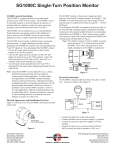
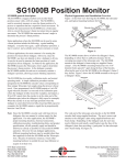
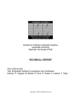
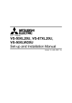
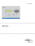
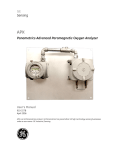
SpeedTalker-DN (XP)
DeviceNet Shaft Speed Sensor with Alarms
USER’S MANUAL
6111 Blue Circle Drive
Minnetonka, MN 55343
Phone: 952.930.0100
Fax: 952.930.0130
ISO 9001:2000 Certified
Free Catalog and Application Assistance
1.800.328.6170
Visit Us Online
www.electro-sensors.com
990-002300 Revision B
Organization
1.
2.
Overview
Operation
3.
Setup
4.
2.1
2.2
2.3
Indicator LEDs
Speed measurement
Alarm Functions
3
3
4
3.1
3.2
3.3
3.4
3.5
3.6
Mechanical installation
Wiring, power-up, getting on-line
Set MAC ID, Baud Rate
Configure parameters
Configure scanner
Interpreting I/O data
5
6
6
6
7
7
4.1
Object model
4.1.1
Objects present
4.1.2
Object interfaces
4.1.3
Objects that affect behavior
4.1.4
Object instance attributes
Identity Object
Message Router Object
DeviceNet Object
Assembly Object
Explicit Messaging Connection Object
Poll I/O Connection Object
COS I/O Connection Object
Speed (application) Object
Alarm (application) Object
I/O Data Format
4.2.1
I/O Assembly instances
4.2.2
Format of I/O Assembly data
4.2.3
I/O Assembly data attribute mapping
Device Configuration
4.3.1
Config. param. listing (EDS), effect on behavior
4.3.2
Configuration parameter mapping (EDS)
4.3.3
Configuration parameter groups (EDS)
Device Profile
4.2
4.3
5.
page
Specifications
8
8
9
9
9
9
9
10
10
11
11
12
13
13
13
14
14
15
16
2
1.
Overview
The SpeedTalker-DN (XP) continuously monitors rotating shaft speed, providing measured RPM and
the status of up to four alarm functions over DeviceNet.
Measurable speed ranges from 0.0 to 6,553.5 RPM. Each configurable alarm function has on/off,
overspeed/underspeed, speed threshold, delay time and minimum on-time settings.
All configuration is handled over DeviceNet with parameter settings stored in non-volatile memory. An
electronic data sheet file (EDS) is provided to aid configuration.
Speed measurement and alarm status are provided over the Poll I/O connection. Alarm status is also
provided over the COS I/O connection for applications requiring sensor-initiated underspeed and/or
overspeed notification (e.g. ‘zero-speed’ sensing).
2.
Operation
2.1
Indicator LEDs
The Network Status and Module Status indicators are located inside the enclosure (remove round cover
to view them). They are provided to aid setup, diagnostics and troubleshooting. Their operation is
standard DeviceNet.
LED state
Off
Flashing Green
Green
Flashing Red
Red
Flashing Red/Green
Network Status (NS)
Not powered / not on-line
On-line, not connected
On-line, connected
IO connection timed-out
Comm fault
Module Status (MS)
Not powered
Device Standby
Device Operational
Minor Fault
Unrecoverable Fault
Device Self-Testing
2.2
Speed measurement
SpeedTalker-DN (XP) detects alternating magnetic pulses from a shaft-mounted rotating Pulser Disk
or Pulser Wrap and converts the pulse frequency into measured speed (RPM) units. The RPM value is
given in the Measured Speed attribute of the Speed object and is also part of the Assembly object’s Data
attribute (Poll I/O connection). See the Device Profile for details.
The Measured Speed is governed by two configuration parameters:
Target Pulses/Rev (PPR)
Set this to the pulses per revolution of the Pulser Disk/Wrap used.
Note that the Target PPR is one-half the number of Pulser Disk/Wrap magnets.
Minimum measurable speed
Sets the minimum shaft speed (RPM) below which the measured RPM will be zero. This is particularly
useful in slower speed applications to reduce the time taken to detect zero RPM.
3
2.3
Alarm functions
Four configurable alarm functions (Alarm 4...1) are provided for detecting underspeed or overspeed
conditions. Each may be used individually or in any combination with the others. All have identical
capabilities and each works independently of the others.
The states (Alarmed/Not-Alarmed) of the four alarm functions are given in the low four bits of the
Alarm Status attribute of the Alarm object and is part of the Assembly object’s Data attribute (Poll I/O
connection).
Alarm Status is also available over the COS I/O connection for applications requiring sensor-initiated
underspeed and/or overspeed notification. See the Device Profile for details.
The following three configuration parameters apply to all four alarm functions:
Alarm 4...1 ON/OFF
The low four bits of this parameter selectively turn the alarm functions ON/OFF.
Alarm 4...1 Over/Under
The low four bits of this parameter set alarm overspeed/underspeed functionality for the alarm functions.
When set for overspeed, a function becomes alarmed when measured speed is greater than the
Overspeed Alarmed trip-point and becomes not-alarmed when it is less than the Not-Alarmed trip-point.
When set for underspeed, a function becomes alarmed when measured speed is less than the Underspeed
Alarmed trip-point and becomes not-alarmed when it is greater than the Not-Alarmed trip-point.
Alarm threshold hysteresis
Works with each function’s Alarm Threshold and Over/Under setting to determine the RPM trip-point
for exiting the Alarmed state. It has no effect on the RPM trip-point for entering the Alarmed state.
Over/Underspeed Alarmed trip-point:
Alarm Threshold
Overspeed Not-Alarmed trip-point:
(1 - %Hysteresis/100) * Alarm Threshold
Underspeed Not-Alarmed trip-point:
(1 + %Hysteresis/100) * Alarm Threshold
Example
for %Hysteresis = 1%, Alarm Threshold = 100.0 RPM, Overspeed:
Alarmed trip-point = 100 RPM, Not-Alarmed trip-point = 99.0 RPM
Each alarm function has the following configuration parameters:
Alarm threshold
Sets the RPM trip-point for entering the Alarmed state. Also works with the Alarm threshold hysteresis
and the function’s Over/Under setting to determine the RPM trip-point for exiting the Alarmed state.
Over/Underspeed Alarmed trip-point:
Alarm Threshold
Overspeed Not-Alarmed trip-point:
(1 - %Hysteresis/100) * Alarm Threshold
Underspeed Not-Alarmed trip-point:
(1 + %Hysteresis/100) * Alarm Threshold
Alarm ON delay
Sets the time that measured speed must be continuously at alarm levels before the function enters
the Alarmed state. This setting is useful for avoiding nuisance alarms resulting from transient speed
excursions into alarm levels.
Alarm ON minimum time
Sets the minimum time a function stays Alarmed once it has entered the Alarmed state.
4
3.
Setup
3.1
Mechanical installation
The SpeedTalker-DN (XP) may be mounted on rigid conduit or with the mounting bracket assembly
(provided).
The gap (A) between the sensing head and the Pulser Disk/Wrap must be 1/16 to 1/4 inch.
The center line of the magnets (B) must allign with the center of the sensing head as the Pulser Disk/
Wrap rotates.
After mounting, remove the round cover and pull network cable through the conduit port into the
enclosure.
B
A
With Pulser Disk Target
�
A
A
With Pulser Wrap Target
5
3.2
1.
Wiring, power-up and getting on-line
After mounting and pulling DeviceNet cable into the enclosure, remove the connector plug from
its socket and connect the color-coded DeviceNet cable wires to the corresponding connector
plug terminals.
�����������
����������
������
������������
��������
MS
�������������
��������������
NS
2.
3.
4.
3.3
1.
2.
3.4
1.
2.
3.
Connector terminals and Indicator LEDs
Re-install the connector plug.
If the network is powered, the LEDs will sequence through a brief test:
Network Status OFF, Module Status GREEN-RED-GREEN, Network Status GREEN-REDOFF.
If there are no MAC ID or Baud Rate conflicts on the network, the Network Status LED should
then flash GREEN indicating the node is on-line but not connected.
Set MAC ID, Baud Rate (DeviceNet Commissioning Tool required)
Once on-line, scan the network to find the SpeedTalker-DN (XP). Once found, you may change
the MAC ID and/or Baud Rate. The factory defaults are MAC ID 63 and Baud Rate 125k.
MAC ID changes take effect immediately, initiating a reset sequence similar to that of power-on.
Baud Rate changes don’t take effect until SpeedTalker-DN (XP) power is cycled off/on.
Configure SpeedTalker parameters (DeviceNet Configuration Tool required)
Register the SpeedTalker-DN (XP) EDS file with your DeviceNet Configuration Tool. Your
DeviceNet Configuration Tool uses this file to create a user-friendly interface to the configuration
parameters.
Speed configuration parameters:
2.1
Target Pulses/Rev (PPR)
Enter the PPR for the Pulser Disk/Wrap used.
Note: The PPR is one-half the number of Pulser Disk/Wrap magnets.
2.2
Minimum measurable speed
Enter the minimum shaft speed (RPM) below which you want the measured RPM to be
zero.
Speed parameters may be changed in either order. Changes take effect immediately.
Alarm configuration parameters:
Set the configuration parameters for any/all desired Alarm functions.
Alarm parameters may be changed in any order. Changes take effect immediately.
6
3.5
1.
2.
Configure Scanner (DeviceNet Configuration Tool required)
Add the SpeedTalker to the Scanner’s scanlist:
Select the SpeedTalker-DN (XP) from the Scanner’s list of available devices and add it to the
scanlist.
Select and map the SpeedTalker Inputs:
2.1
Select the desired SpeedTalker-DN (XP) input (Poll or COS) from the Scanner’s list of
available inputs.
The Poll connection produces the Assembly Object’s data attribute value (Class ID = 4,
Instance = 101, Attribute = 3).
The COS connection produces the Alarm Object’s Alarm Status attribute value (Class ID
= 101, Instance = 1, Attribute = 16).
2.2
Map the selected input to the desired Scanner memory locations.
For the Poll connection, set the byte offset and bit length to map the desired Data
Component (Speed Value, Alarm Status or both) from the I/O Assembly. See 4.2 I/O
Data Format for details.
For Speed Value only, set the byte offset to 0 and bit length to 16.
For Alarm Status only, set the byte offset to 2 and bit length to 8.
For both, set the byte offset to 0 and bit length to 24.
3.6
1.
Interpreting I/O data
Speed Value
Data type:
16-bit unsigned integer (UINT)
User-units:
RPM
Resolution: 0.1 RPM
Minimum value (0x0000) represents 0.0 RPM
Maximum value (0xFFFF) represents 6,553.5 RPM.
Source:
Speed Object’s Measured Speed attribute (class/inst./attr. 100/1/3)
2.
Alarm Status
Data type:
8-bit boolean (BYTE)
Bit assignment:
Bit 0 Alarm 1 status
Bit 1 Alarm 2 status
Bit 2 Alarm 3 status
Bit 3 Alarm 4 status
Bit 4 0 (unused)
Bit 5 0 (unused)
Bit 6 0 (unused)
Bit 7 0 (unused)
Bit encoding:
0 - Not Alarmed
1 - Alarmed
Source:
Alarm Object’s Alarm Status attribute (class/inst./attr. 101/1/16)
7
4.
Device Profile
4.1
Object model
Alarm Object
(application)
Speed Object
(application)
Identity
Object
Assembly
Object
(input)
Message
Router
DeviceNet
Object
I/O
Connection Class
Explicit
Message
DeviceNet Network
4.1.1
Objects present (generic device profile)
4.1.2
Object Interfaces
Object
Identity
Message Router
DeviceNet
Assembly
Connection
Speed (application)
Alarm (application)
Object
Identity
Message Router
DeviceNet
Assembly
Connection(s)
Speed (application)
Alarm (application)
Class ID code
1
2
3
4
5
100
101
Optional/required
Required
Required
Required
Required
Required
[> 1 app. obj. req’d]
[> 1 app. obj. req’d]
# Instances
1
1
1
1
3 (Exp Mes, Poll I/O, COS I/O)
1
1
Interface
Message Router
Explicit Messaging Connection Instance
Message Router
Poll I/O Connection or Message Router
Message Router
Assembly or Message Router
COS I/O Connection, Assembly or Message Router
8
4.1.3
Objects that affect behavior
Object
Identity
Message Router
DeviceNet
Assembly
Connection
Speed (application)
Effect on behavior
Supports the Reset service
No effect
Configures port attributes (baud, MAC ID, BOI proc.)
Defines I/O data format
Contains the number of logical ports into or out of device
Configures pulser-disk ppr, minimum measurable speed
Configures speed thresholds, time delays, min. ON times, over/under functionality,
ON/OFF and hysteresis for Alarm 4... Alarm 1 functions
Alarm (application)
4.1.4
Object instance attributes (by Class, Instance)
Identity Object (Class ID = 1, Instance = 1)
Attrib. ID
1
2
3
Access Rule
Get
Get
Get
4
Get
5
6
7
8
Get
Get
Get
Get
Name
Vendor ID
Device Type
Product Code
Revision
Major rev.
Minor rev.
Status
Serial Number
Product Name
State
Data Type
UINT
UINT
UINT
STRUCT of
USINT
USINT
WORD
UDINT
SHORT- STRING
USINT
Value
804
0 (generic profile)
1
----[realtime code]
[unique code]
“SpeedTalker-DN (XP)”
0-5 (like MS)
Message Router Object (Class ID = 2, Instance = 1)
No externally visible interface to this object instance.
DeviceNet Object (Class ID = 3, Instance = 1)
Attrib ID
1
2
3
4
Access Rule
Get/Set
Get/Set
Get/Set
Get/Set
5
Get
Name
MAC ID
Baud Rate
BOI
Bus-Off Counter
Allocation Info
Allocation Choice
Master’s MAC ID
Assembly Object (Class ID = 4, Instance = 101)
Data Type
USINT
USINT
BOOL
USINT
STRUCT of:
BYTE
USINT
Attrib ID
Access Rule
Name
Data Type
3
Get
Data
Array of bytes:
Value
63 (fac. def.)
0 (fac. def. 125k)
0 (fac. def. OFF)
0 (reset val)
[alloc byte]
[master MAC ID dependent]
Value
Speed (low)
Speed (high)
Alarm4...1
9
Explicit Messaging Connection Object (Class ID = 5, Instance = 1)
Attribute
ID
1
2
3
4
5
6
7
8
9
12
13
14
15
16
17
Access
Rule
Get
Get
Get
Get
Get
Get
Get
Get
Get/Set
Get
Get
Get
Get
Get
Get
Name
State
instance_type
transportClass_trigger
produced_connection_id
consumed_connection_id
initial_comm_characteristics
produced_connection_size
consumed_connection_size
expected_packet_rate
watchdog_timeout_action
produced_conn_path_length
produced_connection_path
consumed_conn_path_length
consumed_connection_path
production_inhibit_time
Data
Type
USINT
USINT
BYTE
UINT
UINT
BYTE
UINT
UINT
UINT
USINT
UINT
EPATH
UINT
EPATH
UINT
Poll I/O Connection Object (Class ID = 5, Instance = 2)
Attribute Access
Data
Name
ID
Rule
Type
1
Get
State
USINT
2
Get
instance_type
USINT
3
Get
transportClass_trigger
BYTE
4
Get
produced_connection_id
UINT
5
Get
consumed_connection_id
UINT
6
Get
initial_comm_characteristics
BYTE
7
Get
produced_connection_size
UINT
8
Get
consumed_connection_size
UINT
9
Get/Set
expected_packet_rate
UINT
12
Get
watchdog_timeout_action
USINT
13
Get
produced_conn_path_length
UINT
14
Get
produced_connection_path
EPATH
15
Get
consumed_conn_path_length
UINT
16
Get
consumed_connection_path
EPATH
17
Get/Set
production_inhibit_time
UINT
Value
0x00 (reset)
0x00 (explicit)
0x83
[slave MAC ID dependent]
[slave MAC ID dependent]
0x21 (prod grp 2, cons grp 2)
37
37
2500 (default in mS)
1 (default - auto delete)
0 (default)
Empty
0 (default)
Empty
0 (mS)
Value
0x00 (reset)
0x01 (I/O)
0x83
[slave MAC ID dependent]
[slave MAC ID dependent]
0x01 (prod grp 1, cons grp 2)
3
0
[must be set]
0 (default - Timed Out state)
6
“20 04 24 65 30 03”
6
“20 64 24 01 30 04”
0 (mS)
10
COS I/O Connection Object (Class ID = 5, Instance = 4)
Attribute
ID
1
2
3
4
5
6
7
8
9
12
13
14
15
16
17
Access
Rule
Get
Get
Get
Get
Get
Get
Get
Get
Get/Set
Get
Get
Get
Get
Get
Get/Set
Name
State
instance_type
transportClass_trigger
produced_connection_id
consumed_connection_id
initial_comm_characteristics
produced_connection_size
consumed_connection_size
expected_packet_rate
watchdog_timeout_action
produced_conn_path_length
produced_connection_path
consumed_conn_path_length
consumed_connection_path
production_inhibit_time
Data
Type
USINT
USINT
BYTE
UINT
UINT
BYTE
UINT
UINT
UINT
USINT
UINT
EPATH
UINT
EPATH
UINT
Value
0x00 (reset)
0x01 (I/O)
0x12 or 0x10 [per ack setting]
[slave MAC ID dependent]
[slave MAC ID dependent]
0x01 or 0x0F [per ack setting]
1
0
[must be set]
0 (default - Timed Out state)
6
“20 65 24 01 30 10”
6
“20 64 24 01 30 04”
0 (mS)
Speed (application) Object (Class ID = 100, Instance = 1)
Attribute
ID
1
2
3
Access
Rule
Get/Set
Get/Set
Get
Name
PPR
Minimum Speed
Measured Speed
Data
Type
UINT
UINT
UINT
Value
8 (fac. def), range: 1 -> 256
10 (fac. def.), range: 1 -> 65535
[measured RPM]
11
Alarm (application) Object (Class ID = 101, Instance = 1)
Attribute
ID
1
2
3
4
5
6
7
8
9
10
11
12
13
14
Access
Rule
Get/Set
Get/Set
Get/Set
Get/Set
Get/Set
Get/Set
Get/Set
Get/Set
Get/Set
Get/Set
Get/Set
Get/Set
Get/Set
Name
Alarm 1 Threshold
Alarm 1 On Delay Time
Alarm 1 On Minimum Time
Alarm 2 Threshold
Alarm 2 On Delay Time
Alarm 2 On Minimum Time
Alarm 3 Threshold
Alarm 3 On Delay Time
Alarm 3 On Minimum Time
Alarm 4 Threshold
Alarm 4 On Delay Time
Alarm 4 On Minimum Time
Threshold % Hysteresis
Alarm 4...1 Overspeed/Underspeed
Get/Set
Select
Data
Type
UINT
USINT
USINT
UINT
USINT
USINT
UINT
USINT
USINT
UINT
USINT
USINT
USINT
BYTE
15
Get/Set
Alarm 4...1 On/Off Settings
BYTE
16
Get
Alarm (4...1) Status
BYTE
Value
10 (fac. def), range 1 -> 65535
0 (fac. def), range 0 -> 250
0 (fac. def), range 0 -> 250
10 (fac. def), range 1 -> 65535
0 (fac. def), range 0 -> 250
0 (fac. def), range 0 -> 250
10 (fac. def), range 1 -> 65535
0 (fac. def), range 0 -> 250
0 (fac. def), range 0 -> 250
10 (fac. def), range 1 -> 65535
0 (fac. def), range 0 -> 250
0 (fac. def), range 0 -> 250
10 (fac. def), range 0 -> 250
0x00 (fac. def),
bit encoding: 1 OVER, 0 UNDER
0x00 (fac. def),
bit encoding: 1 ON, 0 OFF
bit encoding:
1 ALARMED, 0 NOT ALARMED
Application Object (Speed, Alarm) attribute user units:
Speed settings/measurements are in RPM.
Time settings are in seconds.
Hysteresis settings are in %.
Application Object (Speed, Alarm) attribute encoding:
User-units resolution for all integer type (UINT, USINT) attributes (except PPR) is 0.1 (e.g.
integer change of 1 equals 0.1 change in RPM, seconds or %).
User-units resolution for PPR attribute is 1 (integer change of 1 equals PPR change of 1).
Bit assignment for BYTE type attributes
Bit 7
--
Bit 6
--
Bit 5
--
Bit 4
--
Bit 3
Alarm 4
Bit 2
Alarm 3
Bit 1
Alarm 2
Bit 0
Alarm 1
12
4.2
I/O Data Format
4.2.1
I/O Assembly Instances
Number
1
4.2.2
Byte
0
1
2
Type
Input
Name
Input data
Format of I/O Assembly Data
Bit 7
Bit 6
Bit 5
0
0
0
Bit 4
Bit 3
Speed Value Low
Speed Value High
0
Alarm4
4.2.3 I/O Assembly Data Attribute Mapping
Class
Data Component
Name
Number
Name
Speed Value
Alarm Status
Notes:
Speed
Alarm
100
101
Inst.
Number
1
1
Bit 2
Bit 1
Bit 0
Alarm3
Alarm2
Alarm1
Attribute
Name
Number
Meas. Speed
Status
3
16
Data
Type
UINT
BYTE
Speed Value resolution is 0.1 (UINT change of 1 equals 0.1 change in RPM).
I/O Assembly Data (class/inst./attr. 4/101/3) is produced by the Poll connection.
Alarm Status (class/inst./attr. 101/1/16) is produced by the COS connection.
13
4.3
Device Configuration
Configurable parameters and definition of public interface
4.3.1
Configuration parameter listing (EDS) and effect on behavior
4.3.2
Configuration Parameter Mapping (EDS)
Number
Name
1
Target pulses/rev
2
Minimum meas. speed
3
Measured speed (read-only)
4
Alarm 1 threshold
5
Alarm 1 ON delay
6
Alarm 1 ON min time
7
Alarm 2 threshold
8
Alarm 2 ON delay
9
Alarm 2 ON min time
10
Alarm 3 threshold
11
Alarm 3 ON delay
12
Alarm 3 ON min time
13
Alarm 4 threshold
14
Alarm 4 ON delay
15
Alarm 4 ON min time
16
Alarm threshold hysteresis
17
Alarm 4...1 OVER/UNDER
18
Alarm 4...1 ON/OFF
19
Alarm (4...1) status (read-only)
Number
Name
1
2
3
4
5
6
7
8
9
10
11
12
13
14
15
16
17
18
19
Target pulses/rev
Minimum measurable speed
Measured speed (read-only)
Alarm 1 threshold
Alarm 1 ON delay
Alarm 1 ON min time
Alarm 2 threshold
Alarm 2 ON delay
Alarm 2 ON min time
Alarm 3 threshold
Alarm 3 ON delay
Alarm 3 ON min time
Alarm 4 threshold
Alarm 4 ON delay
Alarm 4 ON min time
Alarm threshold hysteresis
Alarm 4...1 Over/Under
Alarm 4...1 ON/OFF
Alarm (4...1) status (read-only)
Effect on behavior
Sets target +/- pulses per revolution for correct RPM reading
Sets the actual speed below which the measured speed is 0
[not write-able - no effect on behavior]
Sets speed levels for Alarm1 Overspeed/Underspeed functions
Time that meas. speed must be at alarm-level for alarmed state
Minimum time Alarm 1 stays alarmed
Sets speed levels for Alarm2 Overspeed/Underspeed functions
Time that meas. speed must be at alarm-level for alarmed state
Minimum time Alarm 2 stays alarmed
Sets speed levels for Alarm3 Overspeed/Underspeed functions
Time that meas. speed must be at alarm-level for alarmed state
Minimum time Alarm 3 stays alarmed
Sets speed levels for Alarm4 Overspeed/Underspeed functions
Time that meas. speed must be at alarm-level for alarmed state
Minimum time Alarm 4 stays alarmed
Sets hysteresis - applies to all Alarm thresholds
bits 3...0 select Alarm 4...1 functions: 1-Overspeed / 0-Under
bits 3...0 turn Alarm 4...1 functions on/off: 1-ON / 0-OFF
[not write-able - no effect on behavior]
Name
Speed
Speed
Speed
Alarm
Alarm
Alarm
Alarm
Alarm
Alarm
Alarm
Alarm
Alarm
Alarm
Alarm
Alarm
Alarm
Alarm
Alarm
Alarm
Class
Number
100
100
100
101
101
101
101
101
101
101
101
101
101
101
101
101
101
101
101
Inst.
Number
1
1
1
1
1
1
1
1
1
1
1
1
1
1
1
1
1
1
1
Attrib.
Number
1
2
3
1
2
3
4
5
6
7
8
9
10
11
12
13
14
15
16
Data Type
UINT
UINT
UINT
UINT
USINT
USINT
UINT
USINT
USINT
UINT
USINT
USINT
UINT
USINT
USINT
USINT
BYTE
BYTE
BYTE
14
4.3.3
Configuration Parameter Groups (EDS)
Group
Number
Group
Name
1
Speed Configuration
2
Alarm Configuration
3
Monitor
Parameter
Number
1
2
3
4
5
6
7
8
9
10
11
12
13
14
15
16
17
18
19
3
19
Parameter
Name
Target pulses/rev
Minimum measurable speed
Measured speed (read-only)
Alarm 1 threshold
Alarm 1 ON delay
Alarm 1 ON min time
Alarm 2 threshold
Alarm 2 ON delay
Alarm 2 ON min time
Alarm 3 threshold
Alarm 3 ON delay
Alarm 3 ON min time
Alarm 4 threshold
Alarm 4 ON delay
Alarm 4 ON min time
Alarm threshold hysteresis
Alarm 4...1 Over/Under
Alarm 4...1 ON/OFF
Alarm (4...1) status (read-only)
Measured speed (read-only)
Alarm (4...1) status (read-only)
Note: The configuration parameters are defined in the Electronic Data Sheet (EDS) only. The
SpeedTalker_DN (XP) does not contain Parameter Objects.
15
5.
Specifications
Measurable shaft speed range
0.0 to 6,553.5 RPM
Pulse frequency range
0.0112 to 31,250 Hz
Measurement accuracy (over temp)
0.02% max error (frequency)
Measurement/setting resolution
0.1 RPM
Pulser Disk/Wrap pulses/revolution
1 to 256 PPR
Airgap (sensing head to Disk/Wrap)
1/16 to 1/4 inch (2 to 6 mm)
Operating Power (network supplied)
11Vdc (60mA) to 25Vdc (40 mA)
DeviceNet implementation
Node type
Connections
Profile
Baud rates
Indicators
Connector
Configuration
Operating Temperature
-40 to 85 °C (-40 to 185 °F)
Enclosure hazardous locations ratings
Group 2 Only slave
Poll, COS, Explicit Message
Generic Device
125k, 250k, 500k
Module, Network Status
Open style
Electronic Data Sheet (EDS)
Class I, Div 1, Group C, D
Class II Groups E, F, G
UL File: E249019
Weight (with bracket)
2.45 Lb (1.11 kg)
Dimensions (with bracket)
(in inches)
0.25
1.84
4.40
1.38
4.81
3.90
4.00
2.38
1" NPT
1.250
0.260
2.750
1.630
0.560
0.316
Specifications are subject to change without notice.
16