1
CHAPTER 5 SAMPLE PROGRAMMING SESSION USING GUI SOFTWARE
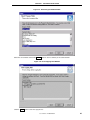
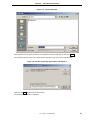
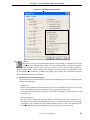
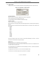
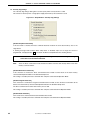
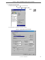
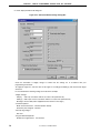
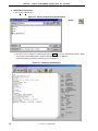
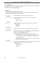
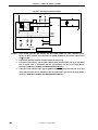
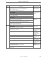
<6> Set the other items in accordance with your programming environment. Especially, set Communication
interface to device and Supply oscillator in accordance with the specifications of the device selected.
Specify a flash memory range to be manipulated as Operation Mode (the flash memory range that can be
set is defined by the parameter file in accordance with the specifications of the device).
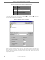
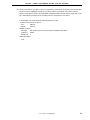
In this example, it is assumed that the following settings are made.
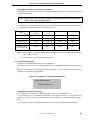
<Communication interface to device>
Port:
SIO-H/S
Speed:
625 kHz
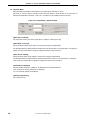
<Supply oscillator>
On Target:
Not checked (The clock of the PG-FP4 is supplied to the target.)
Frequency:
6 MHz
Multiply rate:
5
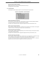
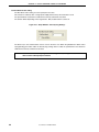
<Operation Mode>
Chip
User’s Manual U15260EJ4V0UM
73