1
RESCUE ROBOT
GO TING LOONG
A thesis submitted in fulfillment of the
requirements for the award of the degree of
Bachelor of Engineering (Electrical-Mechatronics)
Faculty of Electrical Engineering
Universiti Teknologi Malaysia
JUNE 2012
ii
iii
Acknowledgements
First and foremost, I would like to take this opportunity to express
my sincerest gratitude towards my project supervisor, Dr. Zool Hilmi Ismail
for all his guidance, advice, trust and freedom gave to me in the process of
conducts this project.
My outmost thanks also go to my family members who have given
me support throughout the process of conducts this project and my academic
years. Without the support and encouragement from them, I might not be
able to become who I am today.
Last but not least, my sincere appreciation also extends to all my
fellow friends and course mate for your constructive suggestions and
encouragement. The teaching and tips from you are definitely useful for me
to conduct this project.
iv
Abstract
This project presents the development of a low-cost Rescue Robot
where it encompasses into three main parts: mechanical design, wireless
remote control and wireless video transmission.
In the mechanical design, track wheels have been used rather than
conventional wheels to enable the robot to travel through different type
surface or rough terrain. Beside, a pair of lifting arm with has been attached
to the body of the rescue robot in order to climb up the stair or obstacle.
Moreover, a wireless camera has been attached to the robot as a
monitoring system. With the monitoring system, the robot operator is able to
search for survivor or any harmful device.
Last but not least, the robot has been designed by wireless control so
that the operator able to remote controls the robot. The wireless control
allows the operator away from the harmful environment or harmful device
and avoids the wire or cable interrupts the robot motion.
v
Abstrak
Projek ini membincangkan reka bentuk Rescue Robot yang berkos rendah.
Project ini dibahagikan kepada tiga bahagian utama iaitu reka bentuk mekanikal
untuk struktur robot, kawalan jauh tanpa wayar dan penghantaran video tanpa wayar.
Reka bentuk mekanikal untuk struktur robot, roda lipan dipilih dan digunakan
untuk membolehkan Rescue Robot menjalan di atas permukaan yang berlainan.
Selain daripada itu, sepasang lengan mekanikal dipasangkan kepada Rescue Robot.
Tujuan memasanglkan lengan mekanikal adalah membolehkan Rescue Robot
mengatasi tangga atau halangan.
Satu IP kamera tanpa wayar dipasangkan kepada robot tersebut untuk
mengawal and merakamkan “live video” sekeliling Rescue Robot. Dengan kawalan
secara tanpa wayar, operator robot tersebut dapat mengawal situasi kawasan bencana
dan mencari mangsa yang terselamat di kawasan bencana.
Untuk mengelakkan operator Rescue Robot terancam daripada benda atau
alat yang membahayakan, Rescue Robot direka bentuk dengan kawalan jauh tanpa
wayar. Dengan sistem kawalan secara tanpa wayar, robot tersebut tidak akan
mengacaukan operasi robot.
vi
Table of Contents
CHAPTER
TITLE
Acknowledgements
iii
Abstract
iv
Abstrak
v
Table of Contents
vi
List of Table
ix
List of Figure
x
List of Abbreviations
1
2
PAGE
xiii
Introduction
1
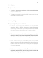
1.1 Overview
1
1.2 Problem Statement
2
1.3 Objectives
5
1.4 Scope of Project
5
Theory and Literature Review
6
2.1 Introduction
6
2.2 Previous Related Works
6
2.2.1 ROBHAZ-DT3
6
2.2.2 Hibiscus
7
2.2.3 Darmstadt Rescue Robot
8
vii
2.2.4 Sandia Gemini-Scout Mine Rescue Robot
3
9
Methodology
3.1 Introduction
11
3.2 Mechanical Design of Robot Structure
11
3.2.1 Main Robot Structure (Tracked Wheel Design)
12
3.2.2 Mechanism Arms Design
13
3.2.3 Track Wheel Motion Design
15
3.3 Components and Electrical Circuitry
16
3.3.1 PIC 16F877A Microcontroller
16
3.3.2 Motor Driver L298
19
3.3.3 Voltage Regulator LM7805
21
3.3.4 PS2 Starter Kit and PS2 Wireless Controller
22
3.3.5 Apexis Wireless IP Camera
24
3.4 Programming and Software Design
25
3.4.1 Flow Chart
27
3.4.2 Microcontroller P16F877A Configuration
30
3.4.3 PS2 Starter Kit Protocol
30
3.4.4 PS2 Starter Kit Signal Processing
31
3.4.4.1 Button Control (Digital Control)
31
3.4.4.2 Joystick Control (Analog Control)
32
3.4.5 Pulse Width Modulation Module
34
viii
4
5
Result and Discussion
35
4.1 Actual Robot
35
4.2 Applications
36
4.3 Live Video
39
Conclusion and Recommendation
41
5.1 Conclusion
41
5.2 Limitations
42
5.3 Recommendation
42
Reference
43
Appendix A
45
Appendix B
53
ix
List of Table
TABLE NO
3.1
TITLE
Major Components Used In This Project
PAGE
16
x
List of Figure
FIGURE NO
TITLE
PAGE
1.1
The statistics of Natural disaster (1990 - 2000)
2
1.2
Mohd Zamri Ramli, Engineering Seismology and
3
Engineering Earthquake Research Group (E-Seer) of the
faculty of civil engineering, Universiti Teknologi
Malaysia
1.3
Dr Norhisham Bakhary, Engineering Seismology and
4
Engineering Earthquake Research Group (E-Seer) of the
faculty of civil engineering, Universiti Teknologi
Malaysia
2.1
ROBHAZ-DT3
7
2.2
Hibiscus
7
2.3
Darmstadt Rescue Robot
8
2.4
Sandia Gemini-Scout Mine Rescue Robot
9
3.1
Three Dimensions Drawing of the Rescue Robot
12
3.2
Rover 5 Tank Chassis Set
12
3.3
Mechanism Arm
14
3.4
Original motor shaft and modified motor shaft
14
3.5
The Tracked Wheel and the Tracked Wheel Coupling
15
3.6
Pin Diagram of PIC16F877A
16
3.7
Circuit Connection of PIC16F877A
17
xi
3.8
Motor Drivers Enable Pin Connection
18
3.9
Motor Driver L298`
19
3.10
Tracked Wheel Motor Driver Circuit Connection
19
3.11
Arms Motor Driver Circuit Connection
20
3.12
Voltage Regulator (LM7805)
21
3.13
Circuit Connection of LM7805
21
3.14
Wireless PS2 Controller
22
3.15
PS2 Controller Starter Kit
23
3.16
Apexis Wireless IP Camera
24
3.17
MPLAB IDE Work Place
25
3.18
USB ICSP PIC Programmer V2010
26
3.19
PS2 Starter Kit Protocol
30
3.20
Syntax of PS2 Starter Kit (Digital Control)
32
3.21
The declaration of four unsigned character for analog
32
control
3.22
Syntax of PS2 Starter Kit (Analog Control)
34
3.23
PWM Module Initialization
34
4.1
Front view of Rescue Robot
35
4.2
Top view of Rescue Robot
36
4.3
Moving on the grass Surface
36
4.4
Moving on the rock surface
37
4.5
Moving on the sand surface
37
4.6
Moving on the unsafe condition
38
xii
4.7
The live video received by laptop
`39
4.8
The live video received by smart phone
39
4.9
The live video received by Laptop and Smart Phone
40
simultaneously
xiii
List of Abbreviations
PS2
-
PlayStation 2
IP
-
Internet protocol
PIC
-
Peripheral Interface Controller
UART
-
Universal Asynchronous Receiver/Transmitter
IC
-
Integrated Circuit
1
CHAPTER 1
INTRODUCTION
1.1
Overview
A robot can be defined as a programmable, self-controlled device consisting
of electronic, electrical, or mechanical units. More generally, it is a machine that
functions in place of a living agent. Robots are especially desirable for certain work
functions because, unlike humans, they never get tired; they can endure physical
conditions that are uncomfortable or even dangerous; they can operate in airless
conditions; they do not get bored by repetition; and they cannot be distracted from
the task at hand.
Due to the several advantages of the robot, it has been used for industry
production and domestic application. One of the domestic robots is V-Bot Robotic
Vacuum Cleaner (RV-8) which having smart cleaning program that enables sequence
of four cleaning movements and several sensor such as Cliff-avoidance sensor to
prevents V-Bot from falling down staircases. In industry application, the robots are
use to position car frames, bolt pieces together, and even do welds and priming.
From the statement above, it is known that the robot is very useful and
helpful for our human being. However, the robot may have other function other than
helping human being in their life. In fact, the robot may save our life as well when
the robot was used it the rescue propose. In the country having natural disaster like
Japan, China and Philippines, the development of the rescue robot is gaining
momentum. However, the development trend in Malaysia is still far behind those
2
countries. In fact, Malaysia may face the natural disaster in the future according the
research of several researchers and experts.
1.2
Problem Statement
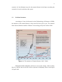
According to Centre for Research on the Epidemiology of Disasters (CRED),
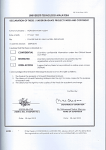
the statistics of the natural disaster is keep increase from year to year. The statistics
below showed that the number of disaster is increasing yearly from 1990 to 2000.
Figure 1.1: The statistics of Natural disaster (1990 - 2000)
Malaysians think earthquakes will never occur in the country. But in reality,
they do, with the most recent one with its epicentre in Manjung, Perak, occurring on
29 April 2009.
3
In fact, Malaysia has a small history of earthquakes. The region around Sabah,
especially around Ranau, Kudat and Lahad Datu, is no stranger to earthquakes, and
according to a seismological expert, it is not uncommon for two or three to strike the
area yearly.
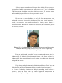
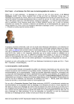
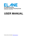
Beside, according to the Engineering Seismology and Engineering
Earthquake Research Group (E-Seer) of the faculty of civil engineering, Universiti
Teknologi Malaysia, there is a possibility of a much larger earthquake occurring in
Malaysia, especially if the earthquakes in Indonesia trigger the inactive fault lines
running in peninsular Malaysia.
Figure 1.2: Mohd Zamri Ramli, Engineering Seismology and Engineering
Earthquake Research Group (E-Seer) of the faculty of civil engineering,
Universiti Teknologi Malaysia
Dr Norhisham Bakhary, another researcher from E-Seer, says that with the
exception of the Penang Bridge and KLCC, buildings or structures in Malaysia are
not designed to resist the force of an earthquake.This means that if an earthquake
with a high magnitude occurred in Malaysia, there is a high possibility that most
buildings would collapse.
Dr Norhisham says that buildings in this country are only designed for a top
or “normal” load and not for a lateral or side-to-side load which earthquakes cause.
He adds that for buildings to be able to withstand earthquakes, structural members
have to be bigger in size, besides many other design considerations. This means more
material is needed for construction, which translates into higher costs.
4
“Nobody wants to spend that much because they think it will never happen. I
have spoken to building owners but no one really seems to care,” says Dr Norhisham.
“The firemen can‟t check the connections which are covered. Do we have to wait
until something happens before we take any preventive action?”
He says that to ensure buildings are still safe after an earthquake, postearthquake assessment is essential, which would first entail visual inspection. If
needed, non-destructive tests can be conducted to identify unseen damage in
structural members. Based on the results of the assessment, the rehabilitation process
can proceed, if required.
Figure 1.3: Dr Norhisham Bakhary, Engineering Seismology and Engineering
Earthquake Research Group (E-Seer) of the faculty of civil engineering,
Universiti Teknologi Malaysia
From the statistics and research of several researcher and experts, there is a
high possibility for Malaysia facing the natural disaster in the future and there is a
high possibility that most buildings in would collapse since Malaysian do not take
earthquake into account.
If the disaster suddenly happens in Malaysia, are Malaysia Polis Force and
Malaysian Fire and Rescue Department able to rescue the victim immediately?
As a leader of technology institution in Malaysia, something should be done to
prevent or reduce the affect before any disaster happens in Malaysia with the
advanced technology knowledge.
5
1.3
Objectives
The objectives of this project are:
1. To develop a low-cost rescue robot that have highly potential and demand in
the present and future market.
2. To design a robot to search for the survivor in the disaster area and assist the
rescue worker in the rescue mission.
1.4
Scope of Project
The scopes of study of this project are as followed:
1. In the robot structure design, track wheels have been used rather than
conventional wheels to enable the robot to travel through different type
surface or rough terrain. Besides, a pair of lifting arm with has been attached
to the body of the rescue robot in order to climb up the stair or obstacle.
2. The wireless control system and the wireless monitoring system was used in
this project to allows the robot operator away from the harmful environment
or harmful device and avoids the wire or cable interrupts the robot motion.
3. For the wireless control system, wireless PS2 controller and Cytron PS2
Starter kits was used to control the robot motion. Beside, the microcontroller
P16F877A interface was used as the main processing unit and C language as
the programming language.
4. For the wireless monitoring system, a wireless IP camera has been attached to
the robot as a monitoring system. The video from the wireless IP camera can
directly view by using computer, laptop or smart phone.
6
CHAPTER 2
THEORY AND LITERATURE REVIEW
2.1
Introduction
This chapter reviews the paper works, researches, books, article and journals which
are related to this title. The theoretical and methodological recommendations from
these academic materials have been studied so that the advantages could be applied
to this project.
2.2
Previous Related Works
2.2.1
ROBHAZ-DT3
ROBHAZ-DT3, the Robot for Hazardous Application, has been created for Korean
troops in Iraq. It was jointly developed by Yujin Robot and the state-run Korea
Institute of Science and Technology. It is equipped with portable remote controlled
station and wireless communication of Image & data.
7
Figure 2.1: ROBHAZ-DT3
It is equipped with laser sensors; this enables the remotely-operated bot to
create a map of the place where a disaster has taken place. Infrared cameras are used
to detect victims. The robot also features foldable arms, four cameras and a set of
temperature sensors. The ROBHAZ-DT3 has a unique set of tank treads that enable
it to adapt easily to uneven terrain. Note that the design allows waterproof, great
flexibility; earlier (and smaller) versions were able to climb stairs.
2.2.2
Hibiscus
Figure 2.2: Hibiscus
Chiba Institute of Technology Japan has developed a new rescue robot named
Hibiscus. This robot‟s main purpose is to look for survivors in case of disasters like
8
earthquakes which are common in Japan. It has an infrared thermal camera which
can detect trapped survivors in the rubble by their heat signature. With the max speed
of 1.1 meters per second, this robot communicates to operator via Wi-Fi 802.11g and
is using a SH-4 processor. Dimensions are 370 mm x 650 mm x 180 mm and weighs
is 22.5 kg. It is powered by a 3700 mAh Lithium Polymer battery which lasts for 60
minutes. It has six independent crawlers and has two flipper arms which allow it to
move over obstacles effortlessly.
2.2.3
Darmstadt Rescue Robot
Figure 2.3: Darmstadt Rescue Robot
The Team Hector Darmstadt established at the Technische Universität
Darmstadt within the PhD program Cooperative, Adaptive and Responsive
Monitoring in Mixed Mode Environments, funded by the German Research
Foundation (DFG). This program addresses the exciting and challenging research
areas of navigation and coordination of multiple autonomous vehicles as well as
monitoring in mixed mode environments that are characterized by the heterogeneity
resources, capabilities and connectivity.
9
The experience in hardware and software of autonomous robots has already
been successfully applied to RoboCup soccer, and there have been studies in
simulation on cooperative control. Different algorithms were developed from
computer vision for people detection and object recognition which can now be
applied to Search and Rescue scenarios. Finally, team members from mechanical
engineering are focusing on the design and experimental evaluation of unmanned
aerial and ground vehicles for environmental monitoring and surveillance
applications.
The team's name was recently changed from "Darmstadt Rescue Robot
Team" to "Hector Darmstadt", which stands for Heterogeneous Cooperating Teams
of Robots.
2.2.4
Sandia Gemini-Scout Mine Rescue Robot
Figure 2.4: Sandia Gemini-Scout Mine Rescue Robot
Gemini-Scout robot, a product of Sandia Labs, can withstand explosions,
crawl over boulders, find its way through 18 inches of water, and navigate through
10
rubble piles. Gemini-Scout having a boot to deliver food, air packs, and medicine to
miners trapped underground before human rescue teams can arrive. But while
Gemini-Scout is impressive, it's not the only rescue robot that first responder teams
have in their arsenal.
Gemini-Scout Mine Rescue Robot is less than 61cm (4 feet) long and 30.5cm
(2 feet) tall, and it is nimble enough to navigate around tight corners and over safety.
Sandia engineers had to build something intuitive for new operators who need to
learn the system quickly, so they used an Xbox 360 game controller to direct the
robot.
To ensure functionality in flooded tunnels, Gemini-Scout‟s controls and
equipment needed to be waterproof. It‟s able to navigate through 45cm (18 inches) of
water, crawl over boulders and rubble piles, and move in ahead of rescuers to
evaluate potentially hazardous environments and help in rescue operations planning.
11
CHAPTER 3
METHODOLOGY
3.1
Introduction
This chapter discussed the complete development process of the rescue robot
including the structure and mechanism, circuitry and also software.
3.2
Mechanical Design of Robot Structure
This section discusses the mechanical design of robot structure and modification of
the original component.
12
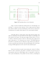
Figure 3.1: Three Dimensions Drawing of the Rescue Robot
3.2.1
Main Robot Structure (Tracked Wheel Design)
Figure 3.2: Rover 5 Tank Chassis Set
13
In order to travel on the racked uneven terrain, tracked wheel is the main
component of the rescue robot. Several tracked wheel have been studied in order to
choose the most suitable tracked wheel for this project. The design, shape, price,
function, limitation of each tracked wheel have been considered. The tracked wheels
was used in this project is Rover 5 Tank Chassis Set.
Rover 5 Tank Chassis Set was chose because there are several advantages of
it. The clearance can be adjusted by rotating the gearboxes in five-degree increments.
“Stretchy” rubber treads maintain tension as the clearance is raised. Besides, inside
of the chassis are 4 noise suppression coils at the bottom and a battery holder that
accepts 6x AA batteries.
Moreover, Rover 5 Tank Chassis Set consists of four motor spaces to install
four motors in the robot structure. In this project, four motors have been installed in
the robot structure. Two motors are used to control the robot motion and there are
named as Tracked Wheel Motors. Another two motors is used to control the
mechanism arms motion and there are named as Arm Motors.
3.2.2
Mechanism Arms Design
The applications of the rescue motor are the real situation may face a lot of obstacles
or stair. In order to move over uneven terrain and up and down stairs, the robot
structure was modified by adding two mechanism arms at the front of the tank
chassis. The mechanism arms were made by removing two tracked wheel from
another Rover 5 Tank Chassis Set. The mechanism arms are support a thin stainless
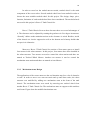
steel beam. Figure show the modified mechanism arm.
14
Figure 3.3: Mechanism Arm
Besides, the motor shaft for the Arms Motor has replaced by a longer steel
shaft in order to attach the mechanism arms to the robot structure. Figure 3.4 show
the original motor shaft and modified motor shaft. The above one is the modified
motor shaft and the below one is the original motor shaft.
Figure 3.4: Original motor shaft and modified motor shaft
15
3.3.3
Track Wheel Motion Design
In the original design, six motors were expected for the whole robot motion
and mechanism arms motion. Due to the limitation of robot structure space, it is very
difficult to install six motors on the robot structure.
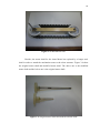
This problem has been overcome by adding a coupling between the tracked
wheel and it is named as Tracked Wheel Coupling. The coupling couples together
the two wheels so that the two tracked wheel on one side can be move by a single
motor. Figure 3.5 show the wheel of the tracked wheel and the Tracked Wheel
Coupling
Figure 3.5: The Tracked Wheel and the Tracked Wheel Coupling
16
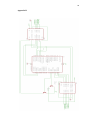
3.3
Components and Electrical Circuitry
This section discusses the electrical circuitry design and components used.
The full circuit connection is show in Appendix B. Table shows the major
components used in this project.
Table 3.1: Major Components Used In This Project
NO.
Components
Quantity
1
PIC16F877A
1
2
L298
2
3
PIC Starter Kits
1
4
PS2 wireless Controller
1
5
PS2 Starter Kit
1
6
Apexis Wireless IP Camera
1
7
Transistor BC547
2
3.3.1
PIC 16F877A Microcontroller
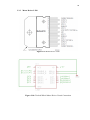
Figure 3.6: Pin Diagram of PIC16F877A
17
Figure 3.7: Circuit Connection of PIC16F877A
Figure 3.6 shows the architecture of PIC16F877A and Figure 3.7 shows the
circuit connection of PIC16F877A. Microcontroller PIC16F877A is a 40 pins
microcontroller which has five I/O ports. PIC16F877A is chosen to be used as the
main processing unit for the rescue robot because it has high enough performance but
with cheaper price, which is only cost about RM20. Besides, this microcontroller has
2 PWM modules with 10 bits resolutions.
The transmitter pin (TX) and receiver pin (RX) is used to communicate with
PS2 Starter Kit. Eight pins of the PIC16F877A are used to control the direction of
four motors. The two pins RC1 and RC2 are used to control the speed of the motors
by Pulse Width Modulation (PWM). Due to the microcontroller only have two PWM
outputs, it is impossible to control four motor speeds simultaneously.
18
The problem has overcome by control the enable pin of the motor diver L298
by two microcontroller pins RB1 and RB0 which connect to a transistor BC547. The
connection is show as Figure. When the output logic of the microcontroller pins RB1
or RB2 is set to 1, the enable pin of the motor drivers L298 will be set to 1 to enable
the motor driver or vice versa.
Figure 3.8: Motor Drivers Enable Pin Connection
By manipulate the programming, only one of the motor drivers will be enable
its corresponding microcontroller pin is set to 1 and another motor driver will be
disabling. As a result, the PWM value will be passing to one of the motor driver only
so that the two different PWM value can be use by only two PWM output. The
connection able the motor speed turning and motor speed control for four DC motors.
Beside, an external crystal of 20Mhz is connected to the PIC18F4550 at pin
15 and 16 as shown in Figure to establish oscillation. For 20Mhz crystal, two 15pF
capacitors are used for oscillator stability purpose.
19
3.3.2
Motor Driver L298
Figure 3.9: Motor Driver L298
Figure 3.10: Tracked Wheel Motor Driver Circuit Connection
20
Figure 3.11: Arms Motor Driver Circuit Connection
Figure 3.9 show the architecture of Motor Driver IC L298 and Figure 3.10
and Figure 3.11 shows the circuit connection. L298 is a high current four channels
driver which is suitable to used for controlling the two DC motors per motor driver
for bidirectional. It is capable of delivering up to 2.5A current output per channel.
Each Motor Driver IC L298 consists of four inputs and four outputs. Four
inputs are connecting to the microcontroller and four outputs are connecting to the
four terminals of two motors. The logic power supply for Motor Driver IC L298 is
5V which is connected to the pin 9 of the IC, while motor power supply for the
motor in this project is 7.4V connected to pin 4 of the IC. The PWM signal from
PIC16F877A is connected to the two enable pin of L298, which are pin 6 and pin 11
in order to control the speed of the motor. Since the PWM signal used is 8 bits, hence
the range of PWM signal used is 0 to 255, with 255 as the maximum speed.
Since the circuit does not require current sensing, pin 1 and pin 15 of Motor
Driver IC L298 is connected to the ground. As mention in the previous part, the
microcontroller only has two PWM outputs, thus it is impossible to control four
motor speeds simultaneously. This problem has been solved by controlling the
21
enable pin (pin 9) of the motor diver L298. The enable pin (pin 9) of the motor diver
L298 is connected to a transistor of BC547 which to two microcontroller pins RB1 or
RB0 and 5V. The connection is showed in the Figure 3.8.
3.3.3
Voltage Regulator LM7805
Figure 3.12: Voltage Regulator (LM7805)
Figure 3.13: Circuit Connection of LM7805
Figure 3.12 shows LM7805 architecture and Figure 3.13shows the circuit
connection of circuit connection for LM7805.
LM7805 is used to supply a stable output voltage 5V to microcontroller
PIC18F4550, motor driver L298 as the logic power supply. LM7805 has internal
current limiting, thermal shut down and safe operating area protection capability. The
output current can goes up to 1A. A heat sinking has been attached to the IC LM7805
to protect the IC from overheat and damage.
22
3.3.4
PS2 Starter Kit and PS2 Wireless Controller
The situation around the rescue robot is unsafe and unpredictable. This is
very difficult to program the rescue robot autonomously. The robot is design to
operate manually by the PS2 controller.
Figure 3.14: Wireless PS2 Controller
Figure 3.14 show Wireless PS2 Controller. PS2 is abbreviation for
Playstation2. Playstation2 wireless controller 2.4 GHz and Cytron PS2 Controller
Starter Kit were utilized to remote control the rescue robot. Play Station 2 (PS2)
controller has been chosen because it easy to obtain from any game store and it offers
good human manual input for control system.
But the major problem to achieve this is the socket for PS2 and the protocol
to communicate with it. PS2 socket is very unique and difficult to obtain. Besides,
protocol to obtain the status (digital and analog) of each button and analog stick on
PS2 controller is difficult.
23
This problem has overcome by using the Cytron PS2 Starter Kit, reading Joystick button‟s state will be easier. It offers a standard connector for Sony PS2
controller to plug-in.
Moreover, the Cytron PS2 Starter Kit is using serial communication over
UART and only require four simply connection on it there are transmitter (TX),
receiver (RX), voltage supply 5V and Ground. Indeed the TX and RX are cross
connected to TX (pin 25) and RX (pin 26) on microcontroller 16F877A. Cross
connection mean the transmitter (TX) of PS2 Starter Kit is connected to the receiver
(RX) of microcontroller 16F877A while the receiver (RX) of PS2 Starter Kit is
connected to the transmitter (TX) of microcontroller 16F877A. The connection
enables the two devices to communicate and transfer data with each other.
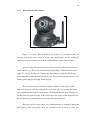
Figure 3.15: PS2 Controller Starter Kit
24
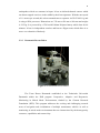
3.3.5
Apexis Wireless IP CAmera
Figure 3.16: Apexis Wireless IP Camera
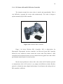
Figure 3.16 show Apexis Wireless IP Camera. As mention before the
situation around the rescue robot is unsafe and unpredictable, Apexis wireless IP
camera was used to monitor and send the captured image to the robot operator.
Apexis wireless IP camera was chose because it has built in servo motor to
rotate camera view. The camera has maximum pitch angle 2
angle 2
and maximum yaw
. Apexis Wireless IP Camera it has the moderate resolution and cheaper
price compared to other wireless IP camera. The video provided by the camera is of a
middle quality but good enough for this project.
The live video can be viewed by computer, laptop or smart phone. This
makes the operator‟s life easier because the live video can view in many ways and
more suitable for the usage of rescue robot. Normally the disaster area is always do
not the electricity power supply, if the electricity power supply of the laptop ran out,
the operator can use smart phone to access the wireless IP camera.
Moreover, the live video can be view simultaneously by computer, laptop and
smart phone. This allows more than one operator to access the live video. The
25
operation mechanism of Apexis wireless IP camera is creating a wireless network
connection around it. The live video can be viewed by connecting the wireless
network with laptop or smart phone. Besides, the Apexis wireless IP camera do not
need software to operate, the wireless IP camera can use any web browser to view
the live video.
3.4
Programming and Software Design
This section discusses the software development process. MPLAB IDE
version 8.63 is used for writing program. C language is used to program the PIC
microcontroller 16F877A. PICkit 2 programmer is used for burning the program into
the microcontroller by using USB programmer.
Program flow chart is also included in the next section. Figure 3.17 shows the
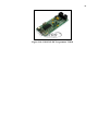
programming workplace of MPLAB IDE. Figure 3.18 shows the USB programmer
used for burning program into microcontroller.
Figure 3.17: MPLAB IDE Work Place
26
Figure 3.18: USB ICSP PIC Programmer V2010
27
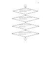
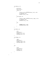
3.4.1
Flow Chart
The rescue robot function mainly base on the signal received from the PS2 controller.
The program flow chart is showed as below.
Start
Received & Reading the signal from the PS2
controller
3
Analog / Digital
Digital
Up Button is pressed.
Analog
Left joystick is moved.
Robot moves forward.
2
Down Button is pressed.
Robot moves backward.
Right Button is pressed.
Robot moves to right.
Left Button is pressed.
Robot moves to left.
1
28
1
Triangle Button is pressed.
Lift the arms up.
Cross Button is pressed.
Lift the arms down.
3
29
2
Left joystick is move to up direction.
Robot moves forward.
Left joystick is move to down direction.
Robot moves backward.
Left joystick is move to left direction.
Robot moves to left.
Left joystick is move to right direction.
Robot moves to right.
3
30
3.4.2
Microcontroller P16F877A Configuration
The syntax for the configuration bits is __CONFIG ( 0x3F32 ). The
hexadecimal code 3F32 is equivalent to the binary code 0011 1111 0011 0010. The
configuration bits for the PIC microcontroller 16F877A consists of 14 bits only, the
most significance two bits are ignored.
For bits 0 to 1 is 1o which refer to the HS oscillator. For bit 2 is set to 0 to
disable the Watchdog Timer. For bit 3 is set to 0 to disable Power-up Timer Enable.
For bit 6 is set to 0 to disable Brown-out Reset. Bit 7 is for Low-Voltage (SingleSupply) In-Circuit Serial Programming Enable bit was set to 0 so that RB3 is digital
I/O, HV on MCLR must be used for programming.
Bit 8 is set to 1 to off Data EEPROM code protection. Bit 9 and 10 is set to
11 to off the write protection and all program memory may be written to by EECON
control. Bit 11 is set to 1 to disable In-Circuit Debugger. Bit 13 is set 1 to off Code
protection. Bits 4, 5 and 12 is Unimplemented and Read as „1‟.
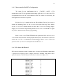
3.4.3
PS2 Starter Kit Protocol
PS2 wireless controller consist 30 buttons on it. In order to differentiate which button
is pressed, PS2 starter Kit uses a unique protocol by defining each button with a
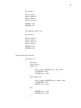
particular number. The PS2 Starter Kit Protocol is showed as Figure 3.19.
#define p_select
#define p_joyl
#define p_joyr
#define p_start
#define p_up
#define p_right
#define p_down
#define p_left
#define p_l2
#define p_r2
#define p_l1
#define p_r1
0
1
2
3
4
5
6
7
8
9
10
11
31
#define p_triangle
#define p_circle
#define p_cross
#define p_square
#define p_joy_lx
#define p_joy_ly
#define p_joy_rx
#define p_joy_ry
#define p_joy_lu
#define p_joy_ld
#define p_joy_ll
#define p_joy_lr
#define p_joy_ru
#define p_joy_rd
#define p_joy_rl
#define p_joy_rr
#define p_con_status
#define p_motor1
#define p_motor2
12
13
14
15
16
17
18
19
20
21
22
23
24
25
26
27
28
29
30
Figure 3.19: PS2 Starter Kit Protocol
3.4.4
PS2 Starter Kit Signal Processing
This section discusses the signal processing of the PS2 Starter Kit. Initially, the logic
of all buttons is 1. The button will be set to 0, when it has been pressed.
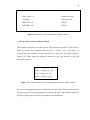
3.4.4.1 Button Control (Digital Control)
The button of the PS2 is used the Digital Logic to control it. When the button is
pressed, the logic state of the up button is equal to 0. Then, the if loop condition
become true, the if loop will be executed. The syntax for the PS2 controller up button
signal processing is show in Figure 3.20.
32
if(skps(p_up)==0)
{
body_motor = 1;
// motor selection
forward();
//move forward
SPEEDL=230;
// PWM
SPEEDR=230;
// PWM
}
Figure 3.20: Syntax of PS2 Starter Kit (Digital Control)
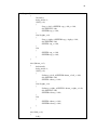
3.4.4.2 Joystick Control (Analog Control)
The joystick of the PS2 is used the joystick angle (analog) to control it. The syntax is
begin by declare four unsigned characters up_v, down_v, left_v and right_v to
represent the four ordinary direction which are up, down, left and right as show in
Figure 3.21. Then, equal the unsigned character to the four direction of the PS2
Starter Kit protocol.
up_v=skps(p_joy_ru);
down_v=skps(p_joy_rd);
left_v=skps(p_joy_ll);
right_v=skps(p_joy_lr);
Figure 3.21: The declaration of four unsigned character for analog control
Next, use the unsigned characters to determine the direction of the joystick. Besides,
by using loop in the loop programming technique, the other four direction which are
up-left, up-right, down- left and down-right can be determined.
33
else if(up_v>0)
{
forward();
body_motor=1;
if(left_v>0)
{
if(up_v>left_v)SPEEDL=up_v-left_v+140;
else SPEEDL=140;
SPEEDR=up_v+140;
}
else if(right_v>0)
{
if(up_v>right_v)SPEEDR=up_v-right_v+140;
else SPEEDR=140;
SPEEDL=up_v+140;
}
else
{
SPEEDL=up_v+140;
SPEEDR=up_v+140;
}
}
else if(down_v>0)
{
backward();
body_motor=1;
if(left_v>0)
{
if(down_v>left_v)SPEEDR=down_v-left_v+140;
else SPEEDR=140;
SPEEDL=down_v+140;
}
else if(right_v>0)
{
if(down_v>right_v)SPEEDL=down_v-right_v+140;
else SPEEDL=140;
SPEEDR=down_v+140;
}
else
{
SPEEDL=down_v+140;
SPEEDR=down_v+140;
}
}
else if(left_v>0)
{
left();
34
body_motor=1;
SPEEDL=left_v+120;
SPEEDR=left_v+120;
}
else if(right_v>0)
{
right();
body_motor=1;
SPEEDL=right_v+120;
SPEEDR=right_v+120;
}
Figure 3.22: Syntax of PS2 Starter Kit (Analog Control)
3.4.5
Pulse Width Modulation Module
In order to use the PWM of the microcontroller to control the motors speed,
the registers CCP1CON and CCP2CON is set to 0b00001100 to enable the PWM
mode of the microcontroller. The PR2 register is set to 255, which means that the
period of the PWM is set to 255. T2CON is set to 4 that enables the timer2. Figure
3.23 shows the initialization code for PWM.
PR2 = 255;
T2CON = 0b00000100;
CCP1CON = 0b00001100;
CCP2CON = 0b00001100;
Figure 3.23: PWM Module Initialization
35
CHAPTER 4
RESULT AND DISCUSSION
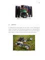
4.1
Actual Robot
Figure 4.1 show the front view and the top view of the actual robot.
Figure 4.1: Front view of Rescue Robot
36
Figure 4.2: Top view of Rescue Robot
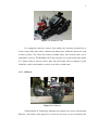
4.2
Applications
As mentioned in the early chapter, the rescue robot is used to monitoring the
situation of the disaster area. The situation of the disaster area is unpredictable and
unsafely. The rescue robot would have the ability to move in the several kind of
surface. Figure 4.3 to Figure 4.6 show the robot move in the various surfaces.
Figure 4.3: Moving on the grass Surface
37
Figure 4.4: Moving on the rock surface
Figure 4.5: Moving on the sand surface
38
Figure 4.6: Moving on the unsafe condition
39
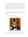
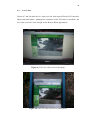
4.3
Live Video
Figures 4.7 and 4.8 show the live video received from Apexis Wireless IP Camera by
laptop and smart phone. Although the resolution of the IP camera is moderate, the
live video received is clear enough for the Rescue Robot applications.
Figure 4.7: The live video received by laptop
Figure 4.8: The live video received by smart phone
40
As mention in the previous chapter, the video from Apexis Wireless IP
Camera can be view simultaneously by computer, laptop and smart phone. Figure 4.9
show the simultaneous video received by laptop and smart phone.
Figure 4.9: The live video received by Laptop and Smart Phone simultaneously
41
CHAPTER 5
CONCLUSION AND RECOMMENDATION
5.1
Conclusion
In conclusion, the rescue robot is able to be remotely controlled by the robot
operator. The live video around the rescue robot is able to feedback to the operator
using the wireless IP camera. Since the operator is able to control the rescue robot
and monitor the situation around the rescue robot, the rescue worker can away from
the dangerous and harmful disaster area and reduce the risk of injury
Beside, the rescue robot is capable to travel on the several type of surface and
avoid the specific obstacles using a modified tracked wheel structure and mechanism
arms. Thus it enables the rescue robot to executes its duty smoothly and
independently.
The objectives of the project are fulfilled.
42
5.2
Limitations
There are some limitations of this project, which are stated follows:
1. The robot structure is modified from original Rover 5 Tank Chassis Set
which made from the plastic material. The plastic material is not strong
enough and hard to modify by welding.
2. The PS2 controller is able to the rescue robot in the range of 2 m only.
3. The wireless IP camera is very high power consume device, a bid battery is
need to operate the wireless IP camera.
4. The original motor of Rover 5 Tank Chassis Set is not enough torque to left
the mechanism arms from flat position ( ).
5.3
Recommendation
For future development purpose, few suggestions are recommended as
follows:
1. Do not modify the original Rover 5 Tank Chassis Set, but direct made a new
tracked wheel platform with metal material.
2. Use other stronger wireless control device to replace the PS2 controller and
PS2 Starter Kit in order to control the rescue robot in bigger range.
3. The Apexis wireless IP camera can be replace by a lower power consume
camera or any live vision device.
4. A high torque DC motor or stepper can be use to replace the original motor of
Rover 5 Tank Chassis Set.
43
REFERENCES
[1] Mary Bellis(2012). The Definition of a Robot. About.com Guide
[2] Engineering Seismology and Earthquake Engineering Research (e-SEER).
(2009). Research Group: Retrived June, 28, 2012, from
http://utm.simple.my/content.php?id=109&cid=81&lang=1
[3] Joseph Loh, and Rashvinjeet S. Bedi (2009, October 11). Unshaken
Complacency. The Star. Retrieved October 11,2009, from
http://thestar.com.my/news/story.asp?file=/2009/10/11/focus/4882460&sec=foc
us
[4] Lee, W., & Park, C. (2004). RoboCup2004 – US Open.
[5] Lee, W., Kang, S., Kim, M., & Park, M. (2004). ROBHAZ-DT3 : Teleoperated
Mobile Platform with Passively Adaptive Double-Track for Hazardous
Environment Applications, 1, 33-38.
[6] Ohno, K., & Yoshida, T. (2009). RoboCupRescue 2009 - Robot League Team <
Pelican United ( JAPAN ) > Rescue Robot League Pelican United ( Japan ).
[7] Germany, H. D., Graber, T., Kohlbrecher, S., Meyer, J., & Petersen, K. (2011).
RoboCupRescue 2011 - Robot League Team, (1).
[8] Soltanzadeh, A. H., Chitsazan, A., Azizah, S., & Ghazali, S. A. (2010).
RoboCupRescue 2010 - Robot League Team, 2009.
[9] Azizah, S., & Ghazali, S. A. (2009). RoboCupRescue 2009 - Robot League
Team.
[10]
Soltanzadeh, A. H., Rajabi, A. H., Alizadeh, A., Eftekhari, G., & Soltanzadeh,
M. (2011). RoboCupRescue 2011 - Robot League Team, 1.
[11]
Billah, M., Ahmed, M., & Farhana, S. (2008). Walking Hexapod Robot in
Disaster Recovery : Developing Algorithm for Terrain Negotiation and
Navigation, 328-333.
[12]
Kadous, M. W., Sheh, R. K.-man, & Sammut, C. (2006). Effective User
Interface Design for Rescue Robotics.
[13]
M.Tandy, S.Winkvist, and K.Young(2010). Competing in the RoboCup
Rescue Robot League. 1 – 15. None
44
[14]
Mohd Syawal Bin Mohamed Abdul Fatah(2006). Tracked Wheel
Development and Implementation for Mobile Robot. Bachelor Degree,
Universiti Teknologi Malaysia, Skudai.
[15]
Lim Choong Honn(2008). Development of A Wireless Mobile Robot.
Bachelor Degree, Universiti Teknologi Malaysia, Skudai.
[16]
Lee Wai Kun(2010), Wheeled Mobile Robot with Motion Control. Bachelor
Degree, Universiti Teknologi Malaysia, Skudai.
[17]
Singapore Robotic(2010). Jaguar Platform User Manual, Singapore:
Singapore Robotic
[18]
Cytron Technologies Sdn. Bhd(2008). PS2 Controller Starter Kit. Skudai,
Johor: Cytron Technologies Sdn. Bhd.
[19]
Microchip Technology Inc(2003). PIC16F87XA Data Sheet. U.S.A:
Microchip Technology Inc.
[20]
Fairchid Semiconductor(2001). MC78XX/LM78XX/MC78XXA 3-Terminal
1A Positive Voltage Gegulator. U.S.A: Fairchid Semiconductor
[21]
STMicroelectronics(2000). Dual Full-Bridge Driver L298. U.S.A:
STMicroelectronicsote
[22]
Shenzhen Apexis Electronic Co.,Ltd(2011), IP Camera Remote Pan/Tilt
Rotate User Manual. China: Shenzhen Apexis Electronic Co.,Ltd(2011)
45
Appendix A
//include
#include <pic.h>
//configuration
__CONFIG ( 0x3F32 );
//
define
#define SPEEDL
#define SPEEDR
CCPR1L
CCPR2L
//Selector for motor driver
#define arm_motor RB1
#define body_motor RB2
//left body motor
#define motor_la
#define motor_lb
RC4
RC5
//right body motor
#define motor_ra
#define motor_rb
RC0
RC3
//left lift motor
#definelmotor_armla RB6
#definelmotor_armlb RB5
//right lift motor
#define lmotor_armra RB4
#define lmotor_armrb RB7
//skps protocol
#definep_select
#define p_joyl
#define p_joyr
#define p_start
#define p_up
#define p_right
#define p_down
#define p_left
#definep_l2
#definep_r2
#define p_l1
#define p_r1
#define p_triangle
#define p_circle
0
1
2
3
4
5
6
7
8
9
10
11
12
13
46
#define p_cross
#definep_square
#define p_joy_lx
#definep_joy_ly
#define p_joy_rx
#define p_joy_ry
#define p_joy_lu
#define p_joy_ld
#define p_joy_ll
#define p_joy_lr
#define p_joy_ru
#define p_joy_rd
#define p_joy_rl
#define p_joy_rr
14
15
16
17
18
19
20
21
22
23
24
25
26
27
#definep_con_status
#define p_motor1
#define p_motor2
28
29
30
//
function prototype
//===========================================================
void init(void);
void forward(void);
void stop (void);
void backward (void);
void reverse (void);
void left(void);
void right(void);
void uart_send(unsigned char data);
unsigned char uart_rec(void);
unsigned char skps(unsigned char data);
void skps_vibrate(unsigned char motor, unsigned char value);
//
main function
//===========================================================
void main(void)
{
unsigned char up_v, down_v, left_v, right_v;
init();
stop();
//initialize microcontroller
//stop all motor
47
while(1)
{
//read joy stick value process
//===========================================================
up_v=skps(p_joy_ru);
down_v=skps(p_joy_rd);
left_v=skps(p_joy_ll);
right_v=skps(p_joy_lr);
//button control for mobilility
if(skps(p_up)==0)
//check "up" button
{
body_motor = 1;
forward();
SPEEDL=230;
SPEEDR=230;
//move forward
}
else if(skps(p_down)==0)
{
body_motor = 1;
backward();
SPEEDL=230;
SPEEDR=230;
}
//check "down" button
else if(skps(p_left)==0)
{
body_motor = 1;
left();
SPEEDL=230;
SPEEDR=230;
}
//check "left" button
else if(skps(p_right)==0)
{
body_motor = 1;
right();
SPEEDL=230;
SPEEDR=230;
}
//check "right" button
else if(skps(p_triangle)==0)
//move backward
//rotate left
//rotate right
48
{
arm_motor=1;
lmotor_armla=1;
lmotor_armlb=0;
lmotor_armra=1;
lmotor_armrb=0;
SPEEDL=230;
SPEEDR=230;
}
else if(skps(p_cross)==0)
{
arm_motor=1;
lmotor_armla=0;
lmotor_armlb=1;
lmotor_armra=0;
lmotor_armrb=1;
SPEEDL=230;
SPEEDR=230;
}
//analog control for mobility
else if(up_v>0)
{
forward();
body_motor=1;
if(left_v>0)
{
if(up_v>left_v)SPEEDL=up_v-left_v+140;
else SPEEDL=140;
SPEEDR=up_v+140;
}
else if(right_v>0)
{
if(up_v>right_v)SPEEDR=up_v-right_v+140;
else SPEEDR=140;
SPEEDL=up_v+140;
}
else
{
SPEEDL=up_v+140;
SPEEDR=up_v+140;
}
}
49
else if(down_v>0)
{
backward();
body_motor=1;
if(left_v>0)
{
if(down_v>left_v)SPEEDR=down_v-left_v+140;
else SPEEDR=140;
SPEEDL=down_v+140;
}
else if(right_v>0)
{
if(down_v>right_v)SPEEDL=down_v-right_v+140;
else SPEEDL=140;
SPEEDR=down_v+140;
}
else
{
SPEEDL=down_v+140;
SPEEDR=down_v+140;
}
}
else if(left_v>0)
{
left();
body_motor=1;
SPEEDL=left_v+120;
SPEEDR=left_v+120;
}
else if(right_v>0)
{
right();
body_motor=1;
SPEEDL=right_v+120;
SPEEDR=right_v+120;
}
else
{
stop();
body_motor=0;
SPEEDL=255;
SPEEDR=255;
}
}
}
50
//===========================================================
// initailization
//===========================================================
void init()
{
// motor PWM configuration
PR2 = 255;
T2CON =
0b00000100;
CCP1CON = 0b00001100;
// set period register
//
// config for RC1 to generate PWM ( for more detail refer datasheet section
'capture/compare/pwm')
CCP2CON = 0b00001100;
// config for RC2 to generate PWM
// Tris configuration (input or output)
TRISA = 0b00000011;
TRISB = 0b00000000;
TRISC = 0b10000000;
TRISD = 0b00000000;
TRISE = 0b00000000;
//set RA0 and RA2 pin as input,other as output
//set RB0-RB4 pin as input, other as output
//set PORTC pin as output
/set all PORTD pin as output
//setup USART
SPBRG = 0x81;
BRGH = 1;
TXEN = 1;
TX9 = 0;
CREN = 1;
SPEN = 1;
RX9 = 0;
RCIE = 0;
// enable all unmasked interrupt
GIE = 0;
PEIE = 0;
}
//set baud rate to 9600 for 20Mhz
//baud rate high speed option
//enable transmission
//enable reception
//enable serial port
//disable interrupt on eachdata received
51
//===========================================================
// uart function
//===========================================================
void uart_send(unsigned char data) //function to send out a byte via uart
{
while(TXIF==0);
//wait for previous data to finish send out
TXREG=data;
//send new data
}
unsigned char uart_rec(void)
{
unsigned char temp;
while(RCIF==0);
temp=RCREG;
return temp;
}
//function to wait for a byte receive from uart
//wait for data to received
//return the received data
//===========================================================
// skps function
//===========================================================
unsigned char skps(unsigned char data)
{
//information on ps controller
uart_send(data);
return uart_rec();
}
//function to read button and joystick
void skps_vibrate(unsigned char motor, unsigned char value)
{
//function to control the vibrator motor
uart_send(motor);
//on ps controller
uart_send(value);
}
//===========================================================
// motor control function
//===========================================================
void forward ()
{
motor_ra = 0;
motor_rb = 1;
motor_la = 0;
motor_lb = 1;
}
52
void backward ()
{
motor_ra = 1;
motor_rb = 0;
motor_la = 1;
motor_lb = 0;
}
void left()
{
motor_la = 1;
motor_lb = 0;
motor_ra = 0;
motor_rb = 1;
}
void right()
{
motor_la = 0;
motor_lb = 1;
motor_ra = 1;
motor_rb = 0;
}
void stop()
{
motor_la = 0;
motor_lb = 0;
motor_ra = 0;
motor_rb = 0;
lmotor_armla = 0;
lmotor_armlb = 0;
lmotor_armra = 0;
lmotor_armrb = 0;
arm_motor = 0;
body_motor = 0;
}
53
Appendix B