1
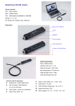
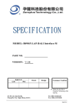
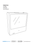
The Zeroplus Logic Analyzer
Installation Guide
Index
Preface ............................................................................................................. 2
1 Features of the Zeroplus Logic Analyzer ................................................ 3
1.1
1.2
1.3
1.4
Package Contents............................................................................................ 3
Introduction ...................................................................................................... 5
Hardware Specifications................................................................................... 8
System Requirements ...................................................................................... 9
1.4.1 Operating System Requirements .......................................................... 9
1.4.2 Hardware System Requirements........................................................... 9
1.5 Device Maintenance and Safety..................................................................... 10
2 Installation................................................................................................ 12
2.1
2.2
2.3
2.4
Software Installation ....................................................................................... 12
Hardware Installation ..................................................................................... 14
Tips and Advice .............................................................................................. 16
Flow of software operation ............................................................................. 18
3 Introduction to Logic Analysis ............................................................... 19
3.1 Logic Analysis ................................................................................................ 19
Task 1. Clock Source (Frequency) and RAM Size set up.................... 19
Task 2. Trigger Properties Setup ......................................................... 21
Task 3. Signal/Bus Trigger Edge Setup ............................................... 26
Task 4. Run to Acquire Data ................................................................ 26
3.2 Bus Logic Analysis ......................................................................................... 28
The Zeroplus Logic Analyzer Installation Guide
Page 1
The Zeroplus Logic Analyzer
Installation Guide
Preface
This Quick Start Guide is designed to help new and intermediate users navigate and
perform common tasks with the Zeroplus Logic Analyzer. Despite its simple packaging
and interface, the Logic Analyzer is a sophisticated measurement and analysis tool. It is
also a highly sensitive electrical current sensing device. Users must carefully read
instructions and procedures pertaining to installation and operation. Any instrument
connected to the unit should be properly grounded. A pair of anti-static gloves is strongly
recommended when performing a task with the device. To ensure accuracy and
consistency of output data, use of the bundled components is strongly recommended.
User opinions are very important to Zeroplus. Please contact our engineering team
by telephone, fax or email with your questions or feedback. Thank you for choosing
the Zeroplus Logic Analyzer.
The Zeroplus Logic Analyzer Installation Guide
Page 2
The Zeroplus Logic Analyzer
Installation Guide
1
Features of the Zeroplus Logic Analyzer
In this chapter, users will learn about the package contents, description, hardware
specifications, system requirements, and safety issues of the Zeroplus Logic Analyzer.
Though this chapter is purely informative, we highly recommend reading this carefully to
ensure safety and accuracy when performing any operation with the Zeroplus Logic
Analyzer.
1.1
Package Contents
Verify the package contents before discarding packing materials. The following
components should be included with your product. For assistance, please contact our
nearest distributor.
Table 1-1: Parts list for retail packages
Models
LAP-16128U
LAP-32128U-A
Logic Analyzer
1
1
16-Pin Testing
0
1
Cable
8-Pin Testing Cable
2
2
Probe
20
36
USB Cable
1
1
Getting Started
1
1
Guide
Driver CD**
1
1
1-PinTesting Cable
1
1
(White)
2-Pin Testing Cable
1
1
(Black)
LAP-321000U-A
1
1
2
36
1
1
1
1
1
* This Driver CD consists of a multilingual software interface program, as well as a
multilingual User’s Manual.
The Zeroplus Logic Analyzer Installation Guide
Page 3
The Zeroplus Logic Analyzer
Installation Guide
16-Pin x 1
8-Pin x 2
Fig. 1-1: Logic Analyzer
Fig. 1-3: Probes
(varied depending on models)
Fig. 1-2: Testing Cables
Fig. 1-4: USB Cable
Fig. 1-5: Getting Started Guide
Fig. 1-6: Driver CD
Fig. 1-7: 1-Pin External Clock Wire
(White)
Fig. 1-8: 2-Pin Ground Wire
(Black)
The Zeroplus Logic Analyzer Installation Guide
Page 4
The Zeroplus Logic Analyzer
Installation Guide
1.2
Introduction
Zeroplus
Logic
Analyzer
models
LAP-16128U,
LAP-32128U-A
and
LAP-321000U-A all share the same external features as illustrated in the following
figures.
Fig. 1-9: A view of the Zeroplus Logic Analyzer LAP-A Series. see Fig 1-12 for detailed
information on the Signal Connectors.
Fig. 1-10: Side view of the Zeroplus Logic Analyzer, which draws its power
from the USB connection.
The Zeroplus Logic Analyzer Installation Guide
Page 5
The Zeroplus Logic Analyzer
Installation Guide
Fig. 1-11: The above illustration demonstrates how the Base Stand Support may be
adjusted. Gently pull the plate away from the analyzer, rotate it 90° and release it.
Fig. 1-12: Rear view of the Zeroplus Logic Analyzer LAP-A Series.
Port A: A0 ~ A7
Port B: B0 ~ B7
Port C: C0 ~ C7
Port D: D0 ~ D7
For signal transmission to
active other instruments.
For the External Clock
connection.
The Zeroplus Logic Analyzer Installation Guide
For extended modules
or devices not
designated to be
analyzed.
For grounding test
circuits.
Page 6
The Zeroplus Logic Analyzer
Installation Guide
: List of functional pins in each model.
Models
LAP-16128U
Port A ( A0~A7)
X
Port B ( B0~B7)
X
Port C ( C0~B7)
Port D ( D0~B7)
R_O
X
T_O
X
S_O
X
CLK
GND
VDD
IOA
IOB
IOC
GND
X
X
X
X
X
X
X
LAP-32128U-A
X
X
X
X
X
X
X
LAP-321000U-A
X
X
X
X
X
X
X
X
X
X
X
X
X
X
X
X
X
X
X
X
X
Table 1-2: Definitions and Functions of pins for all models.
CLK
Clock
GND
Ground
Connects a given external module to be analyzed.
Two pins used for grounding the Logic Analyzer with a
given external module to be analyzed.
Table 1-3: Definitions and Functions of pins for advanced models (1).
R_O
Read (Out)
T_O
Trigger (Out)
S_O
Start (Out)
When the Logic Analyzer is about to upload data from
memory to the PC, the R_O will send a Rising Edge
signal of DC3.3V. When the upload is finished, a
Falling Edge signal is sent.
When a trigger condition is established, the T_O will
send a Rising Edge signal of DC3.3V. When memory
is full, a Falling Edge signal is sent.
When a user initiates a sampling task by clicking the
RUN icon in the window or clicking the START button
on the device, the R_O will send a Rising Edge signal
of DC3.3V. When the Logic Analyzer finishes
uploading, a falling edge signal is sent.
The Zeroplus Logic Analyzer Installation Guide
Page 7
The Zeroplus Logic Analyzer
Installation Guide
Table 1-4: Definitions and Functions of pins for advance models (2).
VDD
Voltage Drain
(Semiconductor)
IOA
Ext. I/O Module A
IOB
IOC
GND
Ext. I/O Module B
Ext. I/O Module C
Ground
1.3
Provides +3.3 V for external modules by draining
voltage from the Logic Analyzer.
Transmits signals from an external model or device
not being tested.
Same as IOA.
Same as IOA.
Grounds external devices, in sequence
Hardware Specifications
Table 1-5: Hardware specifications of LAP-A Model.
Items\Type
Interface
Operating System
Power Supply
Channels
Bandwidth
Memory
Memory Depth
(Per Channel)
Internal Clock Rate
(asynchronous)
Max External Clock
(synchronous)
Trigger Channels
Trigger Condition
Pre-Trigger/
Post-Trigger
Trigger Level
Trigger Count
Max Trigger Page
Enable Channel
Buses Data Decoded
LAP-16128U
LAP-32128U-A
LAP-321000U-A
USB 2.0 (1.1)
98SE/ME/2000/XP
USB 1.1 (USB 2.0 Recommended)
16
32
75MHz
4M Bits
128 Kbits
1 MBits
100 ~ 200 MHz
Max 100MHz
16 Channels
32 Channels
Edge/Pattern
Yes
1 Level
1-65535
Max 8191
16
Enable Delay
Compression
128 KBits
32
Yes
Start: Edge and Pattern
End: 1-65535
16 Channel
Compression
The Zeroplus Logic Analyzer Installation Guide
24 Channel Compression 1-255
Page 8
The Zeroplus Logic Analyzer
Installation Guide
1.4
System Requirements
This section discusses basic operating system and hardware requirements for the
Logic Analyzer. Software and hardware capabilities may vary depending on PC
configuration,. This manual assumes proper installation of a supported operating
system as listed below.
1.4.1 Operating System Requirements
In this sub-section, we share our experiences testing the Zeroplus Logic Analyzer on
the following Microsoft Windows operating systems. Since the Zeroplus Logic Analyzer
requires operating system support of the USB protocol, Windows 95r2 and earlier OS
versions are incompatible.
1)
2)
3)
4)
Windows 98, 98 Second Edition - supported
Windows ME –supported
Windows 2000 Professional, Server Family - supported
Windows XP Home, Professional Editions (32-Bit versions) - supported
1.4.2 Hardware System Requirements
z
CPU
Windows NT, 98, 98 SE
166 MHz, or above.
Windows 2000, XP
300 MHz, or above (strongly suggest 900 MHz, or above).
We have tested various 32-Bit and 64-Bit CPUs. Overall, we find that all
32-Bit CPUs work very well with Logic Analyzer software. Moreover, we find that
AMD’s 64-Bit CPUs, except Opteron, with a 64-Bit Windows operating system,
work just fine with Logic Analyzer; no significant problems occur.
z
Memory
Windows NT, 98, 98 SE
128 MB or above (64 MB minimum).
Windows 2000, XP
256 MB or above (128 MB minimum).
z
Hard Drive
At least 100 Mb available space.
z
USB
USB 1.1 compatible (recommend USB 2.0).
z
Display Devices (recommended)
1. 17” monitor with 1024x786 resolution or higher.
2. 8MB SDRAM on Video Card.
The Zeroplus Logic Analyzer Installation Guide
Page 9
The Zeroplus Logic Analyzer
Installation Guide
1.5
Device Maintenance and Safety
Follow these instructions for proper operation and storage of the Logic Analyzer.
Table 1-7: General Advice
Cautions
•
•
•
•
Do not place heavy objects on the Zeroplus Logic Analyzer.
Avoid hard impacts and rough handling.
Protect the Logic Analyzer from static discharge.
Do not disassemble the Zeroplus Logic Analyzer; this will void
the warranty and could affect its operation.
Cleaning
•
•
Use a soft, damp cloth with a mild detergent to clean.
Do not immerse or spray any liquid on the Zeroplus Logic
Analyzer..
Do not use harsh chemicals or cleaners containing substances
such as benzene, toluene, xylene or acetone.
•
Table 1-8: Electrical Specifications
Items
Minimum
Typical
Maximum
Working Voltage
DC 4.5 V
DC 5.0 V
DC 5.5 V
Current at Rest
200 mA
Current at Work
400 mA
Power at Rest
1W
Power at Work
2W
Error in Phase Off*
± 1.5 ns
Vinput of Testing Channels
± DC 30 V
VReference
DC -6V
DC +6 V
Input Resistance
500KΩ/10pF
Working Temperature
5°C
70°C
Storage Temperature
-40°C
80°C
Table 1-9* refer to the User Manual for error analysis calculation.
The Zeroplus Logic Analyzer Installation Guide
Page 10
The Zeroplus Logic Analyzer
Installation Guide
WARNING
•
•
•
•
•
: Operating Environment
Avoid direct sunlight
Use in a dust free, non-conductive environment (see Note )
Relative Humidity: < 80%
Altitude: < 2000m
Temperature: 0 ~ 40 degrees C
This is a Class A product which may cause radio interference in a
domestic environment.
Note: EN 61010-1:2001 specify degrees of pollution and their
requirements. Logic Analyzer falls under Level 2.
Pollution refers to ‘addition of foreign matter, solid, liquid or
gaseous (ionized gases), that may produce a reduction of
dielectric strength or surface resistivity’.
Pollution Degree 1: No pollution or only dry, non-conductive
pollution occurs. This pollution has no effect.
Pollution Degree 2: Normally only non-conductive pollution
occurs. Occasionally, however, temporary conductivity caused by
condensation must be expected.
Pollution Degree 3: Conductive pollution occurs or dry,
non-conductive pollution occurs which becomes conductive due
to condensation. In such conditions, equipment is normally
protected against exposure to direct sunlight, precipitation and
wind, but neither temperature nor humidity is controlled.
Storage
Environment
Relative Humidity: < 80%
Temperature: 0 ~ 50 Degrees C
Conclusion
After reading this section, users should have a basic grasp of the Logic Analyzer. A
complete understanding of the Safety and Care Recommendations section is a
critical prerequisite of any further operation as presented in the User Manual.
The Zeroplus Logic Analyzer Installation Guide
Page 11
The Zeroplus Logic Analyzer
Installation Guide
2
Installation
This chapter describes installation of the Logic Analyzer hardware and software.
Software installation steps must be followed precisely to ensure successful installation.
2.1
Software Installation
In this section, users will learn how to install the software interface and drivers. As
with proper installation of many USB devices, the Logic Analyzer application and driver
software must be installed prior to connection of the hardware. The following steps
illustrate an installation of a Zeroplus LAP-32128U-A Logic Analyzer. The other two
models mentioned in Chapter 1 would follow identical procedures.
Step 1. Insert the driver CD-ROM in the PC CD drive.
Step 2. Execute the installation program. Go to the START menu, click START,
click Run, click Browse, select Setup.exe file in the appropriate model
folder and then click OK. It is recommended that all other programs are
closed while installation proceeds.
Step 3. Choose the desired language.
Step 4. Click Next to proceed with the Install wizard
Step 5. Select “I accept the term in this license agreement, ” and click Next.
Step 6. Enter User and Organization name.
Step 7. Choose the setup type. We recommend Complete for most users.
Step 8. Click Install to confirm settings and begin actual installation.
Step 9. Click Yes to acknowledge the Microsoft Digital Signature message and
continue the installation.
Step 10. Click Finish to complete the installation.
Step 11. Click Yes to restart the PC.
The Zeroplus Logic Analyzer Installation Guide
Page 12
The Zeroplus Logic Analyzer
Installation Guide
The Zeroplus Logic Analyzer Installation Guide
Page 13
The Zeroplus Logic Analyzer
Installation Guide
2.2
Hardware Installation
Hardware installation simply involves connecting the Logic Analyzer to your
computer with the included USB Cable as shown in Figures 2-4 and 2-5.
1. Plug the fixed end of the cables into
the LA (Fig.2-1).
Fig. 2-1
2. Plug the loose ends into the
connectors on the circuit board to be
analyzed (Fig.2-2).
Note: The following sequence must be
observed when connecting the
connectors into the circuit board: A0 =
Brown, A1 = Red, A2=Orange and so
on.
Fig. 2-2
3. The circuit board must be grounded to
the Logic Analyzer with the
connecting cables (Fig.2-3).
Fig. 2-3
Step 1 Step 2 -
Plug the thin male end of the USB cable into the laptop or PC.
Plug the square female end into the logic analyzer.
The Zeroplus Logic Analyzer Installation Guide
Page 14
The Zeroplus Logic Analyzer
Installation Guide
4. Plug the square end of the USB cable
into the Logic Analyzer (Fig.2-4).
Fig. 2-4
5. Plug the thin end into the computer
(Fig.2-5).
Fig. 2-5
At this point, the computer should be able to detect the Logic Analyzer and finalize the
installation for hardware connection. For further information, refer to the Troubleshooting
and Frequently Asked Questions (FAQ) chapters in the User Manual.
Fig. 2-6: An assembly of Laptop, Logic Analyzer, and a testing board.
The Zeroplus Logic Analyzer Installation Guide
Page 15
The Zeroplus Logic Analyzer
Installation Guide
2.3
Tips and Advice
1.
When testing a circuit board, make sure that the internal sampling frequency (within
the Logic Analyzer) is at least four times the external board frequency.
2.
If the signal connector does not work well with the pins on the test board, try using the
supplied probes.
Fig. 2-7: Probes supplied with the Zeroplus.
3. Usages of probes
3-1. Take the loose end of the cable and
insert it into the clip.
Fig. 2-8
3-2. Compress the probe as shown to
reveal 2 metal prongs (Fig.2-8).
3-3. Place the metal prongs on a metal
connector on the motherboard and
release the fingers so that the
prongs grip the metal connector
(Fig.2-9).
Fig. 2-9
The Zeroplus Logic Analyzer Installation Guide
Page 16
The Zeroplus Logic Analyzer
Installation Guide
4.
The Logic Analyzer will connect to the Zeroplus server for software updates if an
internet connection is available.
5.
Unwanted signals can be filtered out using the Enable or Enable Delay functions.
6.
When measuring for a long period, Compression makes memory more efficient.
7.
Trigger condition depends on the test board. If triggering does not work well, try
narrowing the trigger conditions and optimize them repeatedly.
8.
If a test board has a lower frequency than Logic Analyzer, sample signals according
to the external clock.
9.
When clocking by an external clock, filter extra signals with the Enable function.
10. Unused channels may be removed from the Bus/Signal display using Bus/Signal
(Menu) Î Channel Setup.
The Zeroplus Logic Analyzer Installation Guide
Page 17
The Zeroplus Logic Analyzer
Installation Guide
2.4
Flow of software operation
The Zeroplus Logic Analyzer Installation Guide
Page 18
The Zeroplus Logic Analyzer
Installation Guide
3
Introduction to Logic Analysis
Chapter 3 gives detailed instructions in performing two basic analysis operations
and five advance analysis applications with the Logic Analyzer. The basic analytical
operations are the Logic Analysis and the Bus Analysis, which are fundamental to all
further applications.
3.1
Logic Analysis
Logic Analysis is meant for a single signal analysis. Section 3.1 gives detailed
instructions on the software’s basic setup.
Basic Software setup of the Logic Analysis
Task 1. Clock Source (Frequency) and RAM Size set up
Step 1. Click
icon or Click Sampling Setup from Bus/Signal on the menu bar,
the dialogue as shown in Fig 3-1 will appear.
Fig 3-1 – Clock Source
The Zeroplus Logic Analyzer Installation Guide
Page 19
The Zeroplus Logic Analyzer
Installation Guide
Step 2. Internal Clock (Asynchronous Clock)
Click on Internal Clock, and then select the Frequency from the pull down
menu to set up the frequency of the device under test (DUT). The frequency
of the Internal Clock must be at least four times higher then the frequency
of the Oscillator on the DUT. Or, select the frequency
from
the pull down menu on Tool Bar as Fig 3-2 shows.
Tip: Connect the signal output pin of the tested board to the Signal connector of
Logic Analyzer to measure it using the internal clock of Logic Analyzer.
Fig 3-2 – Clock source drop down menu
External Clock (Synchronous Clock)
Click on External Clock, and then select “Rising Edge” or “Falling Edge” as the
trigger condition of the DUT. In the Frequency column, type the frequency of
the oscillator on the DUT.
Tip: The External Clock is applied when the frequency of the oscillator on the
tested board is less then 100MHz. Connect the output pin of oscillator on the
tested board to the CLK pin of Logic Analyzer as shown in Fig 3-3.
The Zeroplus Logic Analyzer Installation Guide
Page 20
The Zeroplus Logic Analyzer
Installation Guide
Step 3. RAM size
Click on the RAM size
from the pull down menu on the
Sampling Setup dialogue as shown in Fig 3-3.
Fig 3-3 – RAM Size
Tip: The relationship between RAM size, Enable,
as shown in Table 3-1 and Fig 3-3.
Compression and channels
Table 3-1 RAM size vs Enable, and RAM size vs Compression and channels
RAM
sizes/
channel
Channels
available
Compression
Mode &
Enable Mode
RAM
size/
channel
Channels
available
Compression
Mode &
Enable Mode
LAP-16128U
2K ~ 128K
16 channels
Available
256K
16 channels
Disable
LAP-32128U-A
2K ~ 128K
32 channels
Available
256K
16 channels
Disable
LAP-321000U-A
2K ~ 1M
32 channels
Available
2M
16 channels
Disable
Model No.
Task 2. Trigger Properties Setup
icon or Click Properties from the Trigger on the Menu Bar. The
Step 1. Click
dialogue will appear as shown in Fig 3-4.
Fig 3-4 – Trigger Properties
The Zeroplus Logic Analyzer Installation Guide
Page 21
The Zeroplus Logic Analyzer
Installation Guide
Step 2. Trigger Level Setup
Click the drop down menu of Trigger Level on Ports A , B , C and D to select
the Trigger Level as the voltage level that a trigger source signal must reach
before the trigger circuit initiates a sweep.
Tip: There are four commonly used preset voltages for Trigger Level, TTL,
CMOS (5V), CMOS (3.3V), and ECL. Users also may define their own
voltage from -6V to +6V to fit with their DUT.
Port A represents the pins from A0 ~ A7 on the signal connector of the Logic
Analyzer, and so do Ports B, C and D. The voltage of each port may be
configured independently.
Fig 3-5 – Trigger Properties Error
Step 3. Trigger Count.
Type the numbers or select the number from the pull down menu of the Count
on the Tool Bar or Click the pull down menu of the Trigger
Count on the Trigger Properties dialogue as shown in Fig 3-5
The system will be triggered where the Trigger Count is set as shown in
Figs 3-6,3-7 and Fig 3-8.
Fig 3-6 – Trigger Count Drop down Menu
The Zeroplus Logic Analyzer Installation Guide
Page 22
The Zeroplus Logic Analyzer
Installation Guide
Fig 3-7 – Trigger Count Screen shot 1
Fig 3-8 – Trigger Count Screen shot 2
Step 4. Trigger Page/ Delay Time and Clock
The Trigger Page and The Delay Time and Clock can’t be applied at the
same time.
1. Trigger Page:
Click Trigger Page, then Type the numbers or select the numbers from the pull
down menu of the Page
on the Tool Bar or Click the pull down
menu of the Trigger Page on the “Trigger Delay” page of the Trigger Properties
dialogue as shown in Figs 3-9,3-10 and 3-11. The page numbers selected will
be displayed on the screen.
Tip: The Trigger bar (T bar) will not be displayed when the set up of the Trigger
page is more than 1
Fig 3-9 – Trigger Page
The Zeroplus Logic Analyzer Installation Guide
Page 23
The Zeroplus Logic Analyzer
Installation Guide
Fig 3-10 – Trigger Position
Fig 3-11 – Trigger Position and screen
2. Delay Time and Clock
Click the Delay Time and Clock, then type the numbers into the column of the
Trigger Delay Time or type numbers into the Trigger Delay Clock at the
“Trigger Delay” page of the Trigger Properties dialogue as 0 and Fig 0. Or
type the numbers into the column of Trigger Delay
on
the Tool Bar. The system will display the wave start.
Tip: The formula of Delay Time and Clock is “ Trigger Delay Time = Trigger
Delay Clock * (1/ Frequency)”.
The Zeroplus Logic Analyzer Installation Guide
Page 24
The Zeroplus Logic Analyzer
Installation Guide
Step 5. Type the percentages or select the percentages from the pull down menu of the
on the Tool Bar or Click the pull down menu of the Trigger
Position on the “Trigger Delay” page of the Trigger Properties dialogue as
shown in Figs 3-12, 3-13, 3-14, and 3-15, The Trigger Position percentages
selected will be displayed where counted from the right side of the screen of the
system.
Fig 3-12 – Trigger Position Drop down menu
Fig 3-13 – Trigger Position 0%
Fig 3-14 – Trigger Position 10%
Fig 3-15 – Trigger Position 70%
Step 6. Click OK to confirm the setup and exit the Trigger Properties dialogue.
The Zeroplus Logic Analyzer Installation Guide
Page 25
The Zeroplus Logic Analyzer
Installation Guide
Task 3. Signal/Bus Trigger Edge Setup
Highlight a designated signal, and then set its required trigger edge.
1. Left click
to set the signal trigger edge as shown in Fig 3-16.
2. Right click
to set the signal trigger edge as shown in Fig 3-17.
3. Click Trigger on the menu bar and choose a trigger from the list of triggers
as shown in Fig 3-18.
Fig 3-16 – Trigger Left click
Fig 3-17 – Trigger Right Click
Fig 3-18 – Trigger menu
Task 4. Run to Acquire Data
1. Single Run
Click the Single Run
icon from the tool bar or press START button on top of
Logic Analyzer (or press F5), then activate the signal from the DUT to the Logic
Analyzer to acquire the data shown in the wave display area.
2. Repetitive Run
Click the Repetitive Run
icon from the tool bar, then activate continuous
signal to the Logic Analyzer to acquire the repetitive Data, and then click the
stop
icon to end the repetitive run.
Tip: Click
icon to view all the data, and then select the wave analysis tools to
analyze the waves.
The Zeroplus Logic Analyzer Installation Guide
Page 26
The Zeroplus Logic Analyzer
Installation Guide
Fig 3-19 –Click
icon to view all the data
3. Stop to End Run
Click the Stop
icon to End the Run.
Tip: If the status stays displays “Waiting…” with no signal output as shown in Fig 3-20,
click the stop
icon to end the run, check the setup again, and try the run
process again.
Fig 3-20 – Waiting Status
The Zeroplus Logic Analyzer Installation Guide
Page 27
The Zeroplus Logic Analyzer
Installation Guide
3.2
Bus Logic Analysis
Section 4.2 presents detailed instructions about logic analysis with a set of grouped
signals, which is known as Bus Logic Analysis.
Basic Software setup of the Bus Logic Analysis
Step 1. Set up the RAM size, Frequency, Trigger level and Trigger position as
described in Section 3.1.
Step 2. Group Signals into a Bus
Click Channels setup on Bus/Signal of menu bar, or click
The dialogue window shown in Fig 3-21 will appear.
icon.
Fig 3-21 – Channel setup
Rename the bus and set up the signals of the bus as shown in Fig 3-22.
Fig 3-22 – Renaming Bus
1. Click the column with blue, then type the given name of the bus, and then
press enter to confirm it.
2. Go to the relative channels show as shown in the example and, go to
numbers 1,2,3,4,5 which are located on column A and row Bus1. Click
them, to become purple, to set these segments of signals.
3. Click OK to get the result as shown in 0 area 1.
The Zeroplus Logic Analyzer Installation Guide
Page 28
The Zeroplus Logic Analyzer
Installation Guide
Fig 3-23 – Channel setup Window
Tip: Channels Setup
In Dialogue of Channels Setup, there isn’t only Add Bus/Signal, but also
Delete Bus/Signal, Delete All, Restore Defaults functions provided.
1. Delete Bus/Signal, first highlight the bus or channels on area 6 of Fig 3-23,
then click Delete Bus/Signal to delete it.
2. Delete All, click Delete All to delete all bus/signals on area 6 of Fig 3-23.
3. Restore Defaults, click Restore Defaults to restore the dialogue of
Channels Setup as shown in Fig 3-21.
Step 3. Set Trigger condition
1. Highlight the bus which will be triggered then click
icon or select Bus
from the Trigger of the Menu bar, the dialogue window as shown in Fig.
3-24 will appear.
Fig 3-24 – Bus Trigger Setup
Tip: or double click on trigger column of the bus as shown in Fig 3-25.
The Zeroplus Logic Analyzer Installation Guide
Page 29
The Zeroplus Logic Analyzer
Installation Guide
Fig 3-25 – Trigger Column
2. Set Binary, Hexadecimal or Decimal as the signal of the bus to represent
the value(see Fig 3-24).
3. Set “= =” and type the value of bus into value column to set the trigger
condition of the bus.
4. Click OK,
Step 4. Click run and activate the signal from the tested board to the system to get
the result as shown in Fig 3-26.
Tip: Click
icon to view all data, and then select the wave analysis tools to
analyze the waves.
Set Value is 5E as Hexadecimal, and set Operator equal to “= =”, then click
OK, Click run and activate the signal from the tested board to the system to
get the result as the trigger happens on 0X5E.
Fig 3-26 – Bus Trigger Setup
The Zeroplus Logic Analyzer Installation Guide
Page 30