1
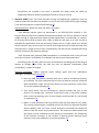
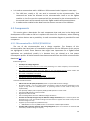
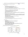
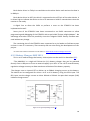
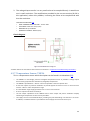
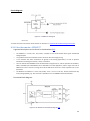
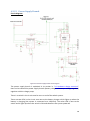
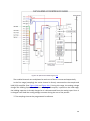
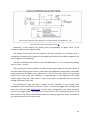
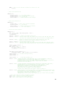
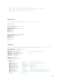
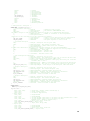
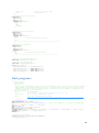
When the feature is enabled, the REFO pin of the PIC24 provides a clock signal derived
from the internal PIC24 clock without software intervention.
4.2.10 Crystal Oscillator
A crystal oscillator is used to generate the clock source of the PIC24 microcontroller. It is
a 12MHz TXC crystal (part number 7B-12.000MEEQ-T).
Circuit diagram
Figure 4.2.10: 12MHz Crystal Circuit Diagram
4.2.11 Connectors
The microcontroller is connected to three different connectors: Stereo Jack, IDC10 and
USB. The purpose and function of these connectors have already been described in “4.1
Hardware design overview”. Here you can find their connection diagrams and some
additional explanations.
I2C implemented interface:
Figure 4.2.11a: Stereo Jack Connector Circuit Diagram
An I2C bus connection has been implemented for the Stereo Jack connector. The I2C
protocol dictates that both the SDA (Serial Data) and SCL (Serial Clock) lines are of opendrain design, thus, pull-up resistors are needed. Pulling the line to ground is considered a
logical zero while letting the line float is a logical one.
26