1
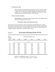
Automatic reclosing function for high voltage networks Function block description Document ID: VERSION 1.0 Budapest, November 2010. IED-EP+ Automatic reclosing function for high-voltage networks User’s manual version information Version Preliminary Version 1.0 VERSION 1.0 Date 24.11.2009. 18.06.2010 05.10.2010 11.11.2010. Modification Preliminary version, without technical information Technical information added Naming revision First edition 2/14 Compiled by Petri Petri Csipke Petri IED-EP+ Automatic reclosing function for high-voltage networks CONTENTS 1 Automatic reclosing function for high voltage networks ......................................................4 1.1 Application ....................................................................................................................4 1.2 Mode of operation ........................................................................................................5 1.2.1 Starting the HV automatic reclosing cycle ..........................................................5 1.2.2 Starting the dead time counter ..............................................................................6 1.2.3 The dead time .......................................................................................................6 1.2.4 Special dead time for the first cycle ......................................................................6 1.2.5 Reduced dead time ...............................................................................................7 1.2.6 Three-phase trip ....................................................................................................7 1.2.7 Checking the ready state of the circuit breaker ....................................................7 1.2.8 Reclosing with synchronous state supervision .....................................................7 1.2.9 Reclosing with synchronous switching .................................................................8 1.2.10 Impulse duration of the CLOSE command ...........................................................8 1.2.11 Behavior after reclosing ........................................................................................8 1.2.12 Behavior after manual close command ................................................................8 1.2.13 Behavior in case of evolving fault .........................................................................9 1.2.14 The final trip ..........................................................................................................9 1.2.15 “Action time” ..........................................................................................................9 1.2.16 Accelerating trip commands .................................................................................9 1.2.17 Dynamic blocking conditions ............................................................................. 10 1.2.18 “Not Ready” conditions ...................................................................................... 10 1.3 Technical summary ................................................................................................... 11 1.3.1 Technical data .................................................................................................... 11 1.3.2 Summary of the parameters .............................................................................. 11 1.3.3 Summary of the generated output signals ......................................................... 13 1.3.4 Summary of the input signals............................................................................. 14 1.3.5 The symbol of the function block ....................................................................... 14 VERSION 1.0 3/14 IED-EP+ Automatic reclosing function for high-voltage networks 1 Automatic reclosing function for high voltage networks 1.1 Application The HV automatic reclosing function for high voltage networks can realize up to four shots of reclosing. The dead time can be set individually for each reclosing and separately for singlephase faults and for multi-phase faults. The starting signal of the cycles can be generated by any combination of the protection functions or external signals of the binary inputs. The selection is made by graphic equation programming. The automatic reclosing function is triggered if as a consequence of a fault a protection function generates a trip command to the circuit breaker and the protection function resets because the fault current drops to zero or the circuit breaker’s auxiliary contact signals open state. According to the preset parameter values, either of these two conditions starts counting the dead time, at the end of which the HV automatic reclosing function generates a close command automatically. If the fault still exists or reappears, then within the "Reclaim time” (according to parameter setting REC79_Rec_TPar_), started at the close command, the protection functions picks up again and the subsequent cycle is started. If no pickup is detected within this time, then the HV automatic reclosing cycle resets and a new fault will start the procedure with the first cycle again. There are some additional requirements to perform automatic reclosing: The HV automatic reclosing function can be blocked by the variable REC79_Blk_GrO_, for which the user has to compose a graphic logical equation. After a pickup of the protection function, a timer starts to measure the “Action time” (the duration of which depends on parameter setting REC79_Act_TPar_ (Action time)). The trip command must be generated within this time to start reclosing cycles, or else the HV automatic function enters dynamic blocked state. At the moment of generating the close command, the circuit breaker must be ready for operation, which is signaled via binary input REC79_CBRdy_GrO_ (CB Ready). The preset parameter value REC79_CBTO_TPar_ (CB Supervision time) decides how long the HV automatic reclosing function is allowed to wait at the end of the dead time for this signal. If the signal is not received during this dead time extension, then the HV automatic reclosing function terminates and after a “dynamic blocking time” (depending on the preset parameter value REC79_DynBlk_TPar_ (Dynamic Blocking time)) the function resets. Depending on the preset parameter value, the HV automatic reclosing function can influence the operation of the protection functions as well. The binary outputs of the HV automatic reclosing function, indicating the running cycle, can be applied for this purpose in the graphic equation editor. (See Chapter 1.3.5) In case of a manual close command which is assigned to the logic variable REC79_ManCl_GrO_ (Manual Close) using graphic equation programming, a preset parameter value decides how long the HV automatic reclosing function should be disabled after the manual close command. The duration of the close command depends on preset parameter value REC79_Close_TPar_ (Close command time), but the close command terminates if any of the protection functions issues a trip command. VERSION 1.0 4/14 IED-EP+ Automatic reclosing function for high-voltage networks 1.2 Mode of operation The HV automatic reclosing function can control up to four reclosing cycles. Depending on the preset parameter value REC79_CycEn_EPar_ (Reclosing cycles), there are different modes of operation: Disabled 1. Enabled 1.2. Enabled 1.2.3. Enabled 1.2.3.4. Enabled No automatic reclosing is selected, Only one automatic reclosing cycle is selected, Two automatic reclosing cycles are activated, Three automatic reclosing cycles are activated, All automatic reclosing cycles are activated. The function can be switched Off /On using the parameter REC79_Op_EPar_ (Operation). The user can also block the HV automatic reclosing function applying the graphic equation editor. The binary status variable to be programmed is REC79_Blk_GrO_ (Block). If the device is generally blocked, then the HV automatic reclosing function is also blocked. 1.2.1 Starting the HV automatic reclosing cycle Depending on the present parameter value REC79_St_EPar_ (Reclosing started by), the HV automatic reclosing function can be started either by resetting of the TRIP command (setting: Trip reset) or by the binary signal indicating the open state of the circuit breaker (setting: CB open). If the reset state of the TRIP command is selected to start the HV automatic reclosing function, then the conditions are defined by the user applying the graphic equation editor. The binary status variable to be programmed is: REC79_Tr_GrO_ (AutoReclosing Start). If the open state of the circuit breaker is selected to start the HV automatic reclosing function, then additionally to programming the REC79_Tr_GrO_ (AutoReclosing Start) signal, the conditions for detecting the open state of the CB are defined by the user applying the graphic equation editor. The binary status variable to be programmed is: REC79_CBOpen_GrO_ (CB OPEN single-pole). This signal is TRUE if at least one of the poles is open. The HV automatic reclosing function gets the trip commands of the protection functions intended to trigger the reclosing function. The conditions for detecting the triggered state of the protection functions are defined by the user applying the graphic equation editor. The binary status variable to be programmed is: REC79_Tr_GrO_ (AutoReclosing Start). This signal starts a dedicated timer, the elapsed time of which is compared to the preset parameter value REC79_MaxSt_TPar_ (Start-signal Max.Tim). The HV automatic reclosing function enters the dynamic blocking state: If the parameter selected for REC79_St_EPar_ (Reclosing started by) is “Trip reset”, and the trip impulse is too long If the parameter selected for REC79_St_EPar_ (Reclosing started by) is “CB open”, then during the runtime of the timer CB open signal is received) For dynamic blocking state see Chapter 1.2.17. VERSION 1.0 5/14 IED-EP+ Automatic reclosing function for high-voltage networks 1.2.2 Starting the dead time counter In the base case, the dead time counter of any reclosing cycle is started by the starting signal (See Chapter 1.2.1) but starting can be delayed. The delay is activated if the value of the REC79_DtDel_GrO_ (Dead Time St.Delay) status signal is TRUE. The conditions are defined by the user applying the graphic equation editor. This delay is limited by the timer parameter REC79_DtDel_TPar_ (DeadTime Max.Delay). 1.2.3 The dead time For all four reclosing cycles, separate dead times can be defined for single-phase trip commands (as a consequence of single-phase faults) and for three-phase trip commands (as a consequence of multi-phase faults). The timer parameters for single-phase trip commands are: REC79_1PhDT1_TPar_ 1. Dead Time 1Ph REC79_1PhDT2_TPar_ 2. Dead Time 1Ph REC79_1PhDT3_TPar_ 3. Dead Time 1Ph REC79_1PhDT4_TPar_ 4. Dead Time 1Ph The timer parameters for three-phase trip commands are: REC79_3PhDT1_TPar_1 1. Dead Time 3Ph REC79_3PhDT2_TPar_ 2. Dead Time 3Ph REC79_3PhDT3_TPar_ 3. Dead Time 3Ph REC79_3PhDT4_TPar_ 4. Dead Time 3Ph The different dead time settings can be justified as follows: in case of a single-phase fault, only the circuit breakers of the faulty phase open. In this case, due to the capacitive coupling of the healthy phases, the extinction of the secondary electric arc at the fault location can be delayed. Consequently, a longer dead time is needed for the fault current to die out than in the case of a three-phase open state, when no coupled voltage can sustain the fault current. From other point of view, in case of a transmission line connecting two power systems, only a shorter dead time is allowed for the three-phase open state because, due to the possible power unbalance between the interconnected systems, a large angle difference can be reached if the dead time is too long. If only a single phase is open, then the two connected healthy phases and the ground can sustain the synchronous operation of both power systems. 1.2.4 Special dead time for the first cycle This special dead time can be necessary for the following reason: Assume a line between substations A and B, and a protection system without tele-protection. In the event of a three-phase fault near substation B, the protection at A generates a trip command according to the second zone’s time setting only, and starts measuring the dead time with considerable delay as compared to the protection at B, which generates a trip command immediately due to the close-in fault. If the three-phase dead time is too short, the HV automatic reclosing at B may attempt to close the circuit breaker during the running time of the second zone trip at A, which means that the fault is not cleared yet. Consequently, a prolonged dead time is needed if the fault was detected in the first zone. The preset timer parameter value is REC79_3PhDT1_TPar_2 (1. special DT 3Ph). VERSION 1.0 6/14 IED-EP+ Automatic reclosing function for high-voltage networks The special dead time is valid if the REC79_1cyc3PhFlt_GrO_ (3PhFault for Spec.DT1) status signal is TRUE. The conditions are defined by the user applying the graphic equation editor. 1.2.5 Reduced dead time Dead time reduction may be applicable under the following circumstances: If healthy voltage is measured in all three phases during the dead time, this means that no fault exists on the line. In this case, the expiry of the normal dead time need not be waited for, a reclosing attempt can be initiated immediately. The dead time is terminated immediately if the REC79_RDT_GrO_ (Reduced DeadTime) status signal is TRUE. The conditions are defined by the user applying the graphic equation editor. 1.2.6 Three-phase trip The HV automatic reclosing function is prepared to get the general trip command as programmed to the binary input status variable REC79_Tr_GrO_ (AutoReclosing Start) and the three-phase trip signal REC79_3PhTr_GrO_ (3Ph Trip). If no three-phase trip signal is received, then it performs automatic reclosing cycles with the dead times according to the setting for single phase cycles. The three-phase cycles are controlled by the status variable REC79_3PhTr_GrO_ (3Ph Trip). If this is TRUE, three-phase cycles are performed. The conditions are defined by the user applying the graphic equation editor. If, during the cycles, the three-phase dead time is applied once, then all subsequent cycles will consider the three-phase dead time settings, too. Three-phase reclosing can be disabled by the preset parameter value REC79_3PhRecBlk_BPar_ (Disable 3Ph Rec.). If the value of this parameter is TRUE, then if a three-phase trip command is received, the HV automatic reclosing function enters “Dynamic blocked” state. For dynamic blocked state, see Chapter 1.2.17. 1.2.7 Checking the ready state of the circuit breaker At the end of the dead time, reclosing is possible only if the circuit breaker can perform the command. The binary variable REC79_CBRdy_GrO_ (CB Ready) indicates this state. The conditions are defined by the user applying the graphic equation editor. If the circuit breaker is not ready, the controller functions wait for a pre-programmed time for this state. The waiting time is defined by the user as parameter value REC79_CBTO_TPar_ (CB Supervision time). If this condition is not fulfilled during the waiting time, then the HV automatic reclosing function enters “Dynamic blocked” state. For dynamic blocked state, see Chapter 1.2.17. 1.2.8 Reclosing with synchronous state supervision Reclosing is possible only if the conditions required by the “synchro-check” function are fulfilled. This state is signaled by the binary variable REC79_SynRel_GrO_ (SYNC Release). The conditions are defined by the user applying the graphic equation editor. The HV automatic reclosing function waits for a pre-programmed time for this signal. This time is defined by the user as parameter value REC79_SYN1_TPar_ (Sync-check Max.Tim). If the “SYNC Release” signal is not received during the running time of this timer, then the VERSION 1.0 7/14 IED-EP+ Automatic reclosing function for high-voltage networks “synchronous switch” operation is started (See Chapter REC79_ClReq_GrI_ (CloseRequ.SynSwitch) is generated. 1.2.9) and the signal 1.2.9 Reclosing with synchronous switching If the conditions of the synchronous state are not fulfilled, another timer starts. This waiting time is defined by the user as parameter value REC79_SYN2_TPar_ (Sync-switch Max.Tim). This separate function controls the generation of the close command in case of relatively rotating voltage vectors on both sides of the circuit breaker to make contact at the synchronous state of the rotating vectors. For this calculation, the closing time of the circuit breaker must be defined. This mode of operation is indicated by the output variable REC79_ClReq_GrI_ (CloseRequ. SynSwitch). If no switching is possible during the running time of this timer, then the HV automatic reclosing function enters “Dynamic blocked” state and resets. For dynamic blocked state, see Chapter 1.2.17. 1.2.10 Impulse duration of the CLOSE command The “Close” impulse is generated as one of the output status signals of the HV automatic reclosing function REC79_Close_GrI_ (Close command). This signal is common to all three phases. The impulse duration is defined by the user setting the timer parameter REC79_Close_TPar_ (Close command time). 1.2.11 Behavior after reclosing When the close command is generated, a timer is started to measure the “Reclaim time”. The duration is defined by the parameter value REC79_Rec_TPar_ (Reclaim time), but it is prolonged up to the reset of the close command (if the close command duration is longer then the reclaim time set). If the fault is detected again during this time, then the sequence of the HV automatic reclosing cycles continues. If no fault is detected, then at the expiry of the reclaim time the reclosing is evaluated as successful and the function resets. If fault is detected after the expiry of this timer, then the cycles restart with the first reclosing cycle. If the user programmed the status variable REC79_St_GrO_ (Protection Start) and it gets TRUE during the Reclaim time, then the HV automatic reclosing function continues even if the trip command is received after the expiry of the Reclaim time. 1.2.12 Behavior after manual close command This state of manual close command is signaled by the binary variable REC79_ManCl_GrO_ (Manual Close). The conditions are defined by the user applying the graphic equation editor. After a manual close command, the HV automatic reclosing function enters “Not Ready” state for the time period defined by parameter REC79_MC_TPar_ (Block after Man.Close). For “Not Ready” state, see Chapter 1.2.18. VERSION 1.0 8/14 IED-EP+ Automatic reclosing function for high-voltage networks If the manual close command is received during the running time of any of the cycles, then the HV automatic reclosing function enters “Dynamic blocked” state and resets. For dynamic blocked state, see Chapter 1.2.17. 1.2.13 Behavior in case of evolving fault In case of evolving faults (when a single-phase fault detected changes to multi-phase fault), the behavior of the automatic reclosing function is controlled by the preset parameter value REC79_EvoFlt_EPar_ (Evolving fault). The options are “Block Reclosing” or “Start 3Ph Rec.” . If “Block Reclosing” is selected, the HV automatic reclosing function enters dynamic blocked state (See Chapter 1.2.17.), and the subsequent reclosing command is not generated. If “Start 3Ph Rec.” is selected, the HV automatic reclosing function goes on performing the subsequent cycle according to the three-phase parameters. 1.2.14 The final trip If the fault still exists at the end of the last cycle, the HV automatic reclosing function trips and generates the signal for final trip: REC79_FinTr_GrI_ (Final Trip). The same final trip signal is generated in case of an evolving fault if “Block Reclosing” is selected (see Chapter 1.2.13). After final trip, the HV automatic reclosing function enters “Dynamic blocked” state. For dynamic blocked state, see Chapter 1.2.17. A final trip command is also generated if, after a multi-phase fault, a fault is detected again during the dead time. 1.2.15 “Action time” The user can compose a binary status variable to indicate the start of the protection functions, the operation of which is related to the HV automatic reclosing function. This status variable is REC79_St_GrO_ (Protection Start). This signal starts the “Action time”, the duration of which is defined by the preset parameter value REC79_Act_TPar_ (Action time). During the running time, the HV automatic reclosing function waits for the trip command. If no trip command is received, then the HV automatic reclosing function enters “Dynamic blocked” state. For dynamic blocked state, see Chapter 1.2.17. 1.2.16 Accelerating trip commands Depending on boolean parameter settings, the automatic reclosing function block can accelerate trip commands of the individual reclosing cycles. This means that the output “TrAcc” of the function block gets active for the first starting state of the protection function or at the end of the dead time of the running cycle, if the dedicated parameter enables acceleration. This signal needs user-programmed graphic equations to generate the accelerated trip command. VERSION 1.0 9/14 IED-EP+ Automatic reclosing function for high-voltage networks 1.2.17 Dynamic blocking conditions There are several conditions to result dynamic blocked state of the HV automatic reclosing function. This state becomes valid if any of the conditions of the dynamic blocking get TRUE during the running time of any of the reclosing cycles. At the time of the change to start the dynamic blocked state a timer is started, the running duration of which is defined by the time parameter REC79_DynBlk_TPar_ (Dynamic Blocking time). During its running time, no reclosing command is generated. The conditions to start the dynamic blocked state are: There is no trip command during the “Action time” (See Chapter 1.2.15). The duration of the starting impulse for the HV automatic reclosing function is too long (See Chapter 1.2.1). If no “CB ready” signal is received at the intended time of reclosing command (See Chapter 1.2.7) The dead time is prolonged further then the preset parameter value REC79_DtDel_TPar_ (DeadTime Max.Delay) (See Chapter 1.2.2). The waiting time for the “SYNC Release” signal is too long (See Chapter 1.2.9) After the final trip command (See Chapter 1.2.14). In case of a manual close command (See Chapter 1.2.12) or a manual open command (if the status variable REC79_CBOpen_GrO_ (CB OPEN single-pole) gets TRUE without REC79_Tr_GrO_ (AutoReclosing Start)). In case of a three-phase trip command if the preset parameter REC79_3PhRecBlk_BPar_ (Disable 3Ph Rec.) is set to TRUE. (See Chapter 1.2.6) In case of evolving faults, if the parameter setting for REC79_EvoFlt_EPar_ (Evolving fault) is “Block Reclosing” (See Chapter 1.2.13) In case of a general block (the device is blocked, see Chapter 1.2). In a dynamic blocked state, the REC79_Blocked_GrI_ (Blocked) status signal is TRUE (similar to “Not ready” conditions). 1.2.18 “Not Ready” conditions There are several conditions to result “Not Ready” state of the HV automatic reclosing function. This state becomes valid if any of the conditions of the blocking get TRUE outside the running time of the reclosing cycles. Reclosing is disabled by the parameter REC79_Op_EPar_ (Operation) if it is selected to “Off”. (See Chapter 1.2) No reclosing cycles are selected by the parameter REC79_CycEn_EPar_ (Reclosing cycles) if it is set to “Disabled” (See Chapter 1.2) The circuit breaker is not ready for operation: the result of the graphic programming of the binary variable REC79_CBRdy_GrO_ (CB Ready) is FALSE. (See Chapter 1.2.7) After a manual close command (See Chapter 1.2.12) If the parameter REC79_CBState_BPar_ (CB State Monitoring) is set to TRUE and the circuit breaker is in Open state, i.e., the value of the REC79_CBOpen_GrO_ (CB OPEN single-pole) status variable gets TRUE. The starting signal for automatic reclosing is selected by parameter REC79_St_EPar_ (Reclosing started by) to be “CB open” and the circuit breaker is in Open state. In case of a general block (the device is blocked, see Chapter 1.2). In a “Not ready” state, the REC79_Blocked_GrI_ (Blocked) status signal is TRUE (similar to “Dynamic blocking” conditions). VERSION 1.0 10/14 IED-EP+ Automatic reclosing function for high-voltage networks 1.3 Technical summary 1.3.1 Technical data Function Accuracy Operating time ±1% of setting value or ±30 ms Table 1-1 Technical data of the HV automatic reclosing function 1.3.2 Summary of the parameters Enumerated parameters Parameter name Title Selection range Default Switching ON/OFF the HV automatic reclosing function (See Chapter 1.2) REC79_Op_EPar_ Operation Off, On On Selection of the number of reclosing sequences (See Chapter 1.2) Reclosing Disabled, 1. Enabled, 1.2. Enabled, REC79_CycEn_EPar_ 1. Enabled Cycles 1.2.3. Enabled, 1.2.3.4. Enabled Selection of triggering the dead time counter (trip signal reset or circuit breaker open position, see Chapter 1.2.1) Reclosing REC79_St_EPar_ Trip reset, CB open Trip reset Started by Selection of behavior in case of evolving fault (block reclosing or perform three-phase automatic reclosing cycle, see Chapter 1.2.13) Evolving Block REC79_EvoFlt_EPar_ Block Reclosing, Start 3Ph Rec. Fault Reclosing Tables 1-2 The enumerated parameters of the HV automatic reclosing function VERSION 1.0 11/14 IED-EP+ Automatic reclosing function for high-voltage networks Timer parameters Parameter name Title Unit Min Max Step Default Dead time setting for the first reclosing cycle for single-phase fault (See Chapter 1.2.3) REC79_1PhDT1_TPar_ 1. Dead Time 1Ph msec 0 100000 10 500 Dead time setting for the second reclosing cycle for single-phase fault (See Chapter 1.2.3) REC79_1PhDT2_TPar_ 2. Dead Time 1Ph msec 10 100000 10 600 Dead time setting for the third reclosing cycle for single-phase fault (See Chapter 1.2.3) REC79_1PhDT3_TPar_ 3. Dead Time 1Ph msec 10 100000 10 700 Dead time setting for the fourth reclosing cycle for single-phase fault (See Chapter 1.2.3) REC79_1PhDT4_TPar_ 4. Dead Time 1Ph msec 10 100000 10 800 Dead time setting for the first reclosing cycle for multi-phase fault (See Chapter 1.2.3) REC79_3PhDT1_TPar_1 1. Dead Time 3Ph msec 0 100000 10 1000 Special dead time setting for the first reclosing cycle for multi-phase fault (See Chapter 1.2.4) REC79_3PhDT1_TPar_2 1. Special DT 3Ph msec 0 100000 10 1350 Dead time setting for the second reclosing cycle for multi-phase fault (See Chapter 1.2.3) REC79_3PhDT2_TPar_ 2. Dead Time 3Ph msec 10 100000 10 2000 Dead time setting for the third reclosing cycle for multi-phase fault (See Chapter 1.2.3) REC79_3PhDT3_TPar_ 3. Dead Time 3Ph msec 10 100000 10 3000 Dead time setting for the fourth reclosing cycle for multi-phase fault (See Chapter 1.2.3) REC79_3PhDT4_TPar_ 4. Dead Time 3Ph msec 10 100000 10 4000 Reclaim time setting (See Chapter 1.2.11) REC79_Rec_TPar_ Reclaim Time msec 100 100000 10 2000 Impulse duration setting for the CLOSE command (See Chapter 1.2.10) REC79_Close_TPar_ Close Command Time msec 10 10000 10 100 Setting of the dynamic blocking time (See Chapter 1.2.17) REC79_DynBlk_TPar_ Dynamic Blocking msec 10 100000 10 1500 Time Setting of the blocking time after manual close command REC79_MC_TPar_ Block after Man.Close msec 0 100000 10 1000 Setting of the action time (See Chapter 1.2.15) REC79_Act_TPar_ Action Time msec 0 20000 10 1000 Limitation of the starting signal (See Chapter 1.2.1) REC79_MaxSt_TPar_ Start Signal Max Time msec 0 10000 10 1000 Delaying the start of the dead-time counter (See Chapter 1.2.2) REC79_DtDel_TPar_ DeadTime Max Delay msec 0 100000 10 3000 Waiting time for circuit breaker ready signal (See Chapter 1.2.7) REC79_CBTO_TPar_ CB Supervision Time msec 10 100000 10 1000 Waiting time for synchronous state signal (See Chapter 1.2.8) REC79_SYN1_TPar_ Syn Check Max Time msec 500 100000 10 10000 Waiting time for synchronous switching (See Chapter 1.2.9) REC79_SYN2_TPar_ SynSw Max Time msec 500 100000 10 10000 Table 1-3 Timer parameters of the HV automatic reclosing function VERSION 1.0 12/14 IED-EP+ Automatic reclosing function for high-voltage networks Boolean parameters Parameter name REC79_CBState_BPar_ REC79_3PhRecBlk_BPar_ REC79_Acc1_BPar_ REC79_Acc2_BPar_ REC79_Acc3_BPar_ REC79_Acc4_BPar_ REC79_Acc5_BPar_ Title CB State Monitoring Disable 3Ph Rec. Accelerate 1.Trip Accelerate 2.Trip Accelerate 3.Trip Accelerate 4.Trip Accelerate FinTrip Default 0 0 0 0 0 0 0 Explanation Enable CB state monitoring for “Not Ready” state (See Chapter 1.2.18) Disable three-phase reclosing (See Chapter 1.2.6) Accelerate trip command starting cycle 1 (See Chapter 1.2.16) Accelerate trip command starting cycle 2 (See Chapter 1.2.16) Accelerate trip command starting cycle 3 (See Chapter 1.2.16) Accelerate trip command starting cycle 4 (See Chapter 1.2.16) Accelerate final trip command (See Chapter 1.2.16) Table 1-4 Boolean parameters of the HV automatic reclosing function 1.3.3 Summary of the generated output signals The binary output status signals of the HV automatic reclosing function are listed in Table 1-5. Binary status signal Title REC79_Close_GrI_ Close command REC79_FinTr_GrI_ Final Trip REC79_ClReq_GrI_ CloseRequ. SynSwitch REC79_Blocked_GrI_ Blocked REC79_TrAcc_GrI Acceleration Explanation Close command of the HV automatic reclosing function. See Chapter 1.2.10 Indication of final trip state. See Chapter 1.2.14 The closing requires synchronous switching. See Chapter 1.2.9. The HV automatic reclosing function is in blocked state. See Chapter 1.2.17 and Chapter 1.2.18 Trip command acceleration. See Chapter 1.2.16 Table 1-5 The binary output status signals of the HV automatic reclosing function VERSION 1.0 13/14 IED-EP+ Automatic reclosing function for high-voltage networks 1.3.4 Summary of the input signals Binary status signals The HV automatic reclosing function has binary input status signals. The conditions are defined by the user applying the graphic equation editor. The binary input status signals of the HV automatic reclosing function are listed in Table 1-6. Binary status signal REC79_St_GrO_ REC79_Tr_GrO_ REC79_3PhTr_GrO_ REC79_ManCl_GrO_ REC79_CBRdy_GrO_ REC79_DtDel_GrO_ REC79_CBOpen_GrO_ REC79_1cyc3PhFlt_GrO_ REC79_SynRel_GrO_ REC79_Blk_GrO_ REC79_RDT_GrO_ Title Protection Start AutoReclosing Start 3Ph Trip Manual Close CB Ready Dead Time St.Delay CB OPEN single-pole 3PhFault for Spec.DT1 SYNC Release Block Reduced DeadTime Explanation See Chapter 1.2.1 See Chapter 1.2.1 See Chapter 1.2.6 See Chapter 1.2.12 See Chapter 1.2.7 See Chapter 1.2.2 See Chapter 1.2.1 See Chapter 1.2.4 See Chapter 1.2.8 See Chapter 1.2 See Chapter 1.2.5 Table 1-6 The binary input signal of the HV automatic reclosing function 1.3.5 The symbol of the function block Figure 1-1 The function block of the HV automatic reclosing function The names of the input and output signals are parts of the “Binary status signal” names listed in Table 1-5 and Table 1-6. VERSION 1.0 14/14