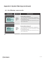
1
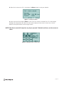
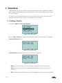
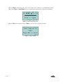
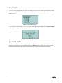
www.sesadesign.com
FARMING PROCESS CONTROLLER
Operational
Manual
Version 1.1
Firmware Version 1.0
page I
Contents
WARRANTY4
DISCLAIMER4
1. Introduction
5
1.1 Overview5
1.2 Specifications6
2. Installation
7
2.1 Mounting the iFarm
7
2.2 Connecting to the iFarm
8
3. Operating the iFarm
9
3.1 Main Screen Display
9
3.2 Navigation9
3.3 Using the Menu System
12
3.4 System Setup
13
4. eUnits
18
4.1 Configuring eUnits
20
4.2 Calibrating eUnits
22
5. Power
24
5.1 Setting Power
6. Alarms
24
26
6.1 Setting Alarms
7. Timelines
7.1 Creating a Timeline
8. Profiles
26
28
28
31
8.1 Set Active Profile
31
8.2 Start New Profile
31
8.3 Save Profile
32
page 1
9. Grow Plans
33
9.1 Creating a Grow Plan
33
9.2 Grow Plan Menu Overview
36
Appendix 1. Quick Start
37
A1.1 Unit Configuration
37
A1.2 Connecting External Devices
38
A1.3 Connecting the eUnit Sensors
39
A1.4 Configuring External Devices - Light Source
40
A1.5 Configuring External Devices - Humidity Sensor
43
Appendix 2. System Warnings
48
A2.1 List of Warnings - setting mismatch
48
A2.2 List of Warnings - power override
49
Appendix 3. Software / Firmware
50
Contact Information
50
page 2
DANGER
Electrocution Hazard!
The system uses live mains voltage!!! Always disconnect the power to the controller and the
external power eUnits before wiring, service or maintenance.
Do not open the iFarm Controller box! There are no user serviceable parts in the device. Any
changes of the internal circuit will void the warranty.
Note:
Install all electrical equipment and wiring in accordance with national and local electric codes.
Note:
The controller is not designed for immersion in water. Please install it in dry locations only
(0-80% RH non-condensing). The controller and additional eUnits can be installed in an approved water-resistant enclosure. The sensors should be installed according to their installation guides.
The Light and Humi sensors provided with the Starter Kit can work in humid (0-95%), noncondensing environments. The sensors operational is temperature 0-70°C. Please refer to
eUnits’ datasheet for operational instructions.
page 3
WARRANTY
Sesa Design Inc. (the “Company”) warrants that all manufactured products are, to the best of its
knowledge, free of defective material and workmanship and warrants the components for the following
period from the date of purchase:
iFarm Controller (the “Product”): one (1) year
This Warranty is extended to the original purchaser of the Product (the “Buyer”) from the date the
Product was purchased. This Warranty does not cover damages from abuse, misuse, accidental breakage, or units that have been modified, altered, or installed in a manner other than that which is specified
in the installation and operation manual. The Company must be contacted prior to return shipment of
the Product for a return authorization. No returns of the Product will be accepted without a return authorization.
This Warranty is applicable only if the Product has been properly stored, installed, and maintained per
the installation and operation manual and used for its intended purpose. This limited Warranty does not
apply when the Product has been installed in or operated under unusual conditions or environments
including, but not limited to, high humidity, high temperature conditions, rain, or inclement weather of
any kind.
If the Buyer’s claim for return authorization complies with the aforementioned restrictions, the Product
shall, at the sole discretion of the Company, be replaced or repaired at no charge.
The Buyer is purchasing the Product “as is,” and this Warranty is provided in lieu of all other warranty
or condition provisions, express or implied, pursuant to the laws of the Province of Nova Scotia and the
Federal laws of Canada, applicable therein, including but not limited to, implied warranties or conditions
of fitness or merchantability for a particular purpose or merchantable quality.
DISCLAIMER
In no event or circumstance shall the Company be liable to the Buyer or any third party for
damages in excess of the price paid for the Product, or for any loss of use, inability to use,
inconvenience, commercial loss, loss of time, lost profits or savings, incidental, consequential,
indirect, special damages, or any other damages arising out of the Buyer’s use or misuse of
the Product, negligence, or willful misconduct.
This Disclaimer is made to the fullest extent allowed pursuant to the laws of the Province of
Nova Scotia and the Federal laws of Canada, applicable therein, and is specifically made to
specify that the liability of the Company under this limited Warranty, or any claimed extension
thereof, shall be to replace or repair the Product or refund the price paid for the Product.
page 4
1. Introduction
1.1 Overview
Bridging the gap between green thumbs & green technology
Farming has come a long way since the days of the horse and plow and the farmer’s almanac. Long
considered an art, modern farming is more about the precise monitoring of the growing environment
and the application of science and technology to improve results. Traditionally the cost to implement
sophisticated measurement and control tools was outside the reach of the hobbyist or small commercial
operation. The iFarm combines state of the art monitoring and control technologies in a single, cost
effective package. Using the iFarm you can recreate well-known ideal growing conditions, controlling fans,
pumps, and lights to maximize your results.
Think of the iFarm as the command and control center for your garden or greenhouse. With the right
sensors and external devices it can independently monitor and control variables such as: temperature,
humidity, light intensity, pH, EC/TDS, CO2 and others.
A
External eUnits Input
B
C
D
USB Cable Connector
External eUnit
Power Input
External eUnit
Power Input
Multi-Function
Menu Buttons
Power Cable
Connector
page 5
1.2 Specifications
Physical Specifications
• Dimensions: 138mm (H) x 113mm (W) x 45mm (D)
• Weight: 320 g
• Display: Monochrome, 128 x 24 pixels, color backlight
• Operating temperature: 0°C - 75°C
Electrical
• 115 VAC/60Hz operating power
• Four built in outlets (3 Amps each)
• Up to four channels (15 Amps each)
• Four external unit connectors
• USB connector
Functional
• Independent operation of all connected devices
(Can implement a number of tasks independently or as an integral system)
• Up to 16 external units (sensors, power, communication)
• Eight power scenarios
• Eight alarms
• Eight timelines can control every minute of 24 hours
• Every power scenario controlled by timeline, timer and up to two sensors
• Alarms can be set on sensors or power
• Up to 15 profiles can be stored on the device
• Grow plan schedules different profiles in a timeline
• Coloured backlight changes according to events
• Alarms makes a sound according to their priority
page 6
2. Installation
2.1 Mounting the iFarm
1. Mount the iFarm controller in a dry area away from direct sunlight, condensing humidity, water, rain, or
extreme temperatures, in an easily accessible location at approximately eye level.
Mounting
Holes
Mounting
Holes
FIGURE 2.1.1 iFarm controller with mounting holes
WARNING!
The iFarm controller should be mounted in a dry environment. If the unit is mounted in a moist
environment, it must be in a moisture-protected box to prevent moisture damage.
2. The iFarm is supplied with an external power cord. Make sure there is a power outlet within
approximately 6 feet of where the iFarm controller is mounted.
FIGURE 2.1.2 iFarm controller power cord connector
NOTE: Use only the supplied power cord to ensure proper operation and support full power
ability.
3. Use appropriate hardware for mounting the unit. Don’t forget to take into account the weight of the
iFarm power cord, as well as any external devices and sensor eUnits that may be plugged in to the
controller.
4. Mount the iFarm controller flat against the wall using the two holes on each side of the unit. Mounting
screws are not included in the box. Appropriate hardware will depend on the mounting surface. You
may want to raise the iFarm away from the wall slightly to ensure easy access to the side external power
ports.
page 7
FIGURE 2.1.3 iFarm controller external power receptacles
NOTE: The iFarm features four external power receptacles, two on each side of the iFarm.
2.2 Connecting to the iFarm
NOTE: Software is not required for the iFarm controller to function properly. All settings and
device changes can be made from the iFarm controller.
1. To download the optional iFarm software, visit www.sesadesign.com/software and follow the
download instructions.
2. Plug the connector into the USB port on the iFarm controller, and the USB cable into an available
USB port on your computer.
USB Mini-B
Connector
Power Line 1 - Lights
Power Line 3 - Fan
Power Line 2 - Water/
Misters
iFarm controller with three external devices
connected
page 8
3. Operating the iFarm
3.1 Main Screen Display
The iFarm LCD display shows two main areas of information. The left side of the screen shows data from
the attached sensors (if sensors are present), with sensors plugged into the A Input port on the top line,
and sensors plugged into ports B, C and D below.
The right side of the screen displays the controller status, current active profile, current grow plan stage,
and the current time (see Figure 3.1.1).
Current
Sensor
Inputs
Sensor Icon
(Humidity, Light,
CO2,etc.)
Current Active Profile
A
Light
B
Humidity
Current
Grow Plan
Status
C
CO2
D
Time
Current Time
FIGURE 3.1.1 iFarm controller home screen
Current Unit of
Measurement
(%, Lux, °C, etc.)
Current Sensor
Status
Current Sensor
Port
(High, Low, OK, etc.)
(A, B, C, D)
FIGURE 3.1.2
Sensor information on Home Screen
NOTE: The sensor icon on the main screen will change if the sensor type is changed.
3.2 Navigation
The four main buttons on the primary iFarm Controller can be used to navigate the internal menu visible
on the LCD screen. The Exit, Power, Sensors, and Menu buttons allow you to configure the device.
Each button also has an associated arrow above it.These arrows represent how to move with the iFarm
menu structure, once you enter a specific Menu tree.
FIGURE 3.2.1 Multi-Function Menu Buttons
page 9
3.2
Navigation (continued)
The Exit button functions as an “Escape” button; when navigating menus with submenu items, press
Exit to return to the previous submenu item, the previous menu level, or press repeatedly from any
menu to return to the home screen.
FIGURE 3.2.2 Multi-Function Navigation Buttons
The Menu button on the far right is used to access the main iFarm menu. This Menu button also
functions as an “Enter” key to select/save button, and is also used to move from item to item when
configuring sensors or through certain device menus.
FIGURE 3.2.3 Main Menu
The Power button will open an overview window which shows all enabled and configured Power
Entities. This button is also used as the Up button when navigating through sub-menus or scrolling
through options.
FIGURE 3.2.4 Power Menu
page 10
The Sensors button will open an overview window that shows which ports have sensors attached,
as well as the current reading from the sensor. In the case of sensors with multiple readings or
measurements, they will be listed as Port designation followed by a number indicating the reading
number, for example B1, B2, B3. This button is also used the Down button when navigating through
sub-menus or scrolling through options.
FIGURE 3.2.5 Sensors Menu
The iFarm has an Emergency Stop feature, which is accessed by pressing the menu and exit buttons
simultaneously.
The iFarm will return to the home screen if left idle for 2 minutes, and the LCD screen backlight will dim
when not in use. The dimmer setting can be configured under Menu » System » Display » Dimmer.
To disable the Dimmer, leave Dimmer setting at 0.
page 11
3.3 Using the Menu System
The Main menu has 5 sub-items, Profiles, iFarm, eUnits, Grow Plan, and System, providing
access to all the required configuration and control settings for the iFarm.
MENU ITEM
PROFILES
iFARM
eUNITS
GROW PLAN
page 12
OPTIONS
FUNCTION
Set active profile
Choose Default or one of up to 15 programmed
profiles
Start new profile
Set up to 15 individual profiles
Save profile
Save an active profile
Delete profile
Delete a profile; active profiles cannot be deleted
Set Alarms
Set up to 8 Alarm profiles, Select timing model, Set
eUnit port, Configure parameters, Choose sound
Set Power
Choose settings for any available power eUnits.
Power Out: PLine 1-4 (external power units),
Timeline, Timer, & Sensors
Set Timeline
Set Timeline 1-8
Show Time Line
Show visual representation of timelines
24 hour or 15 minute view
Show eUnits
Display data from any available eUnits
Configure eUnit
View list of configurable units; Set eUnit parameters
(units, number of samples, etc.)
Calibrate eUnit
Calibrate applicable eUnit (e.g. CO2 or other
chemical sensor)
Set Defaults
Reset to default settings for individual eUnits
eUnit info
View eUnit Version, Calibration, Configuration, and
Status
Enable
Enable/Disable Grow Plan
Current
Set current position in the grow plan; View current
position
Duration
Set duration of one stage, and stages per plan; View
current settings
Plan Setup
Assign profiles to stages and idle state; View current
settings
3.4 System Setup
MENU ITEM
OPTIONS
DISPLAY
FUNCTION
Line #1 - 4
Choose what information should appear on the home screen.
Information can be assigned to Lines #1 - 4
Format
Select a 24 or 12 hour clock
Dimmer
Set the amount of time the controller must be idle before the screen
will automatically dim
Set the current time (hours, minutes, seconds)
TIME
Yes/No
Enable or disable sound, and control volume
Time
Set the time for an alarm delay
POWER FORCE
Yes/No
Enable manual power force
ALARMS ON
POWER
Yes/No
Enable alarms on power lines
SET DEFAULTS
Yes/No
Reset ALL default settings
SOUND
ALARM DELAY
SYSTEM INFO
Display iFarm unit & firmware version information and unit serial
number
page 13
3.4.1 Display
The Display settings (Menu » System » Display) control the information displayed on the home
screen of the iFarm controller. The settings for Lines #1 - #4 represent the four display areas on the left
hand side of the screen.
FIGURE 3.4.1 Display Menu
In the default settings, Line #1 corresponds to Port A, Line #2 corresponds to Port B, Line #3
corresponds to Port C, and Line #4 corresponds to Port D. Each line can be configured to display either
an available Port, the current time, or no display.
NOTE: Only connected units will be shown as display options.
The time format can also be set to 12 or 24 hour clock in the Display menu (Menu » System »
Display » Format).
3.4.2 Time
To set the current time, navigate to Menu » System » Time. Use the up or down arrows to adjust
and use the menu button to toggle between hours, minutes, and seconds. Press Enter when complete
to return to the System Menu.
FIGURE 3.4.2 Setting the TIme
page 14
3.4.3 Sound
To enable or disable the sound function, navigate to Menu » System » Sound. Use the up or down
arrow buttons to select the desired setting, and press Enter to save.
When the sound is disabled, any alarms sound will be overridden. Alarms will appear on the LCD display,
but the alarm will not sound.
FIGURE 3.4.3 Setting the Volume
3.4.4 Alarm Delay
The alarm delay allows you to configure a set delay between the time when a timeline, and associated
devices are activated, and when any alarm is enabled. This allows time for the devices associated with the
timeline to begin working, and the environmental variables to stabilize before an alarm is sounded.
FIGURE 3.4.4 Setting an Alarm Delay
NOTE: The alarm delay is only applied to TimeLine operated alarms. It has no effect for
alarms set to Always.
For example, a system with a pump and water level meter has an alarm set for the when water level
is below the meter. There is a physical delay between when the pump starts to operate and when
the actual water level rises. If the alarm is set to the same timeline as the pump, it will be operated
immediately.
Setting an alarm delay can prevent the alarm sounding before the pump has a chance to take effect.
To set an alarm delay, navigate to Menu » System » Alarm Delay. Use the up or down arrows to
select the number of seconds delay, and press Enter to save.
page 15
3.4.5 Power Force
The Power Force option, when set to yes, allows you to force any particular Power Entity to ON, OFF or
AUTO. To enable or disable manual power force, navigate to Menu » System » Power Force. Use
the Up or Down arrows to select the desired setting and press Enter to save. Press Exit to return to
the main menu.
FIGURE 3.4.5.1 Enabling Manual Power Force
When Power Force is enabled, press Power to access the Power Entity overview dialog, where you are
now able to manually toggle each individual Power Entity ON, OFF or AUTO.
FIGURE 3.4.5.2 Setting the Manual Power Force
NOTE: Forced Power Entity will override other Power Entities with the same power output.
3.4.6 Alarms on Power
To enable or disable alarms on power lines, navigate to Menu » System » Alarms on Power. Use
the Up or Down arrow buttons to select yes or no, and press Enter to save.
FIGURE 3.4.6 Enabling Alarms on Power lines
page 16
3.4.7 Set Defaults
To restore the iFarm controller to factory default settings, navigate to Menu » System » Set Defaults.
Use the Up or Down arrow buttons to select yes or no, and press Enter to save. The LCD will show
Done! when complete.
FIGURE 3.4.7 Resetting all Default Settings
3.4.8 System Info
To view the iFarm controller system information, navigate to Menu » System » System Info. This
screen displays the controller version, Firmware version, FreeRTOS version, and unit Serial Number.
FIGURE 3.4.8 System Information Screen
page 17
4. eUnits
eUnits states for “external units” and can be one of three types:
1. Sensing unit. The sensing unit may include a builtin sensor (Humi, aLight e.t.c), or external probes
(PH, TDS e.t.c). The eUnit conected to extenal probe called adaptor eUnit.
2. Power unit. The power unit controls external power devices and isolated from the operated voltage.
It also senses the output so if there is no demanded voltage on the output, you’ll get a notification (or
Alarm can be operated). The Power eUnits are available in different voltage ranges – 12VDC, 24VDC,
24VAC and 110VAC.
3. Communication unit. These unit provides wireless communication – WIFI, GPRS and Wireless
extension modules. Also there are two special communication modules – hub and extender. Both
are used for increase connection wire length. WIFI and GPRS module also have log memory for
stand alone logging
page 18
Once an eUnit is plugged in to the iFarm controller through a port on the top of the controller, the eUnit
can be controlled by the iFarm. Sensor eUnits are configured by navigating to Menu » eUnits.
To edit an eUnit’s settings, press the Enter button, and then use the Up or Down arrow buttons to
navigate to eUnits. In this menu you can configure, calibrate, reset defaults, or view the eUnit info.
Current Reading
Units
(Lux)
Sensor Type
(Light)
Current Unit of
Measurement
Sensor Icon
(Humidity, Light,
CO2,etc)
(%, Lux, °C, etc)
Current Sensor
Status
Current Sensor
Port
Port
Status
(High, Low, OK.)
(A, B, C,D)
FIGURE 4a Sensor information on Home
Screen
FIGURE 4b Sensor eUnits ports on the top of the iFarm controller
NOTE: Each different eUnit has different available parameters for configuration and calibration.
page 19
4.1 Configuring eUnits
To configure an eUnit, select Configure eUnit from the eUnit menu by pressing the Enter button, and
then use the Up or Down arrow buttons to navigate to the desired eUnit. Only available eUnits will be
listed, and if there are no available units, the screen will display No units to configure! Configuration
options will differ depending on the type of eUnit.
NOTE: Please refer to eUnit’s datasheet for detailed operation description.
FIGURE 4.1 eUnits Menu
4.1.1 Light Sensor eUnit
FIGURE 4.1.1 Light Sensor Configuration
For example, if the eUnit is a light sensor, the units can be set to Lux or Kilo Lux, and the numbers of
samples required to report a setting can be set. Once you have configured the settings, press the Enter
button to save them.
The screen will show Done! once the setting has been successfully changed.
page 20
4.1.2 Temperature Sensor eUnit
FIGURE 4.1.2 Temperature Sensor Configuration
For the eUnit Temperature sensor, the units can be changed from Celsius to Fahrenheit.
There is also a Heater Feature which can be set to On or Off. The Heater setting should be used with
Extreme Caution. It is designed to heat up the temperature sensor to remove any excess moisture from
the sensor, but using it will result in inaccurate temperature readings, as the heater heats up the sensor
itself. The Heater should be used for specific periods of time, and turned off when not needed. Once the
settings have been configured press Enter to save them.
The screen will show Done! once the setting has been successfully changed. When the heater is on, an
icon appears on the home screen.
page 21
4.2 Calibrating eUnits
Some sensor eUnits may require calibration. As an example the CO2 sensor can be calibrated to either
400PPM or 0PPM. Each sensor will have a different calibration process. Follow the sensor eUnit manual
to perform a calibration procedure.
NOTE: Please refer to eUnit’s datasheet for detailed operation description.
FIGURE 4.2.1 Calibrating a CO2 Sensor
If there are no units that are able to be calibrated, you will see a No unIts to calibrate dialog screen.
FIGURE 4.2.2 No Units to Calibrate Screen
page 22
4.2.1 Resetting the Defaults
Navigate to Menu » eUnits » Set Defaults. Select the eUnit you want to reset and press Enter. Use
the Up and Down arrow buttons to select yes or no, and press Enter to reset the sensor to its factory
defaults.
FIGURE 4.2.3 Reset eUnit Defaults Screen
4.2.2 eUnit Info
Navigate to Menu » eUnits » eUnit info and then select an eUnit. The screen will display which port
the eUnit is plugged in to, the version, whether the eUnit is able to be calibrated, if the eUnit can be
configured, and the eUnit status.
FIGURE 4.2.4 eUnit Information Screen
page 23
5. Power
5.1 Setting Power
The iFarm is equipped with eight programmable power settings (Power Entities) to control external power
devices. To reach the Power entity configuration page navigate to Menu » iFarm » Set Power.
A power port can be one of the four built-in PLines or other connected external power eUnits.
As an example we will be setting Power 1 to control a lamp based on light sensor settings.
1. To Set Power navigate to Menu » iFarm » Set Power.
FIGURE 5.1.1 Set Power 1 to PLine 1
2. Using the Up and Down arrow buttons on the front of the iFarm device, highlight Power 1: None.
Press the Enter button.
3. Using the Up and Down arrow buttons, scroll through the options and Select PLine 1 (where our
lamp is plugged in) as the Power Out and press the Enter button to enter the Power Configuration
dialog.
FIGURE 5.1.2 Power Configuration Dialog
4. Using the Up and Down arrow buttons on the iFarm device, scroll through the available PLines to
choose PLine1, where we connected our light source. Press the Enter button to confirm and move the
cursor to the Timeline option.
5. Use the Up and Down arrow buttons to Select Always and press the Enter button to confirm and
move the cursor to the Timer option.
6. Leave the Timer at 0 00 to disable a timer for the Power Unit.
7. Once you have set the timer, press the Enter button to move to the Sensor 1 settings.
page 24
8. Use the Up and Down arrow buttons to scroll through the available sensor units. Only those units
plugged into the iFarm are available to choose. Once a sensor is selected, the parameters specific to the
selected sensor will appear. For this example, Select A1:Light.
FIGURE 5.1.3 Selecting PLine Sensor 1
9. Adjust the sensor to the desired parameters and press the Enter button to save your selection.
FIGURE 5.1.4 Setting Sensor 1 (light) parameters
10. A Done! message on the iFarm controller screen indicates that your Power settings have been
saved successfully.
FIGURE 5.1.5 Settings Saved
page 25
6. Alarms
6.1 Setting Alarms
The iFarm is equipped with eight programmable alarm settings, to help communicate important
events to you. To reach the Alarm configuration page navigate to Menu » iFarm » Set Alarms.
FIGURE 6.1.1 Set Alarms Menu
Alarms are grouped in sets of two, to create four priority settings. Each priority level is differentiated
by different screen lighting and increased alarm sound intensity. Alarm 1 and Alarm 2 indicate the
lowest priority level, and Alarm 7 and Alarm 8 represent the highest priority level. Priority level also
indicates the order in which alarms will be shown, with the highest priority (Alarm 7 and Alarm 8)
being shown first.
As an example we will be setting Alarm 1 to provide an alert if the light drops below 150 Lux.
1. Select Alarm 1 from the Set Alarms menu.
2. Set the timing to Always and press Enter to save.
FIGURE 6.1.2 Set Alarm Timing
For each alarm, the timing can be set to Always, so that the alarm will respond any time the
parameters are exceeded, or the timing can be assigned a specific timeline, so the alarm only
responds when the corresponding timeline is active.
The cursor will automatically move to the next option, which allows you to choose the sensor eUnit
that will provide the information that we will use to trigger the Alarm.
3. Use the Up and Down arrow buttons to navigate to the A1: Light eUnit and press Enter to save.
Once a sensor is selected its specific parameters will be displayed.
4. Use the Up and Down arrow buttons to navigate between the equal, greater than, or less than
symbols, and press the Enter button to select less than.
page 26
5. Adjust the lux amount to 150 Lux and press the Enter button to save your selection.
FIGURE 6.1.3 Set Alarms Parameters
6. Set the sound to ON and press Enter to save. Even if the sound is turned off, the LCD screen display
backlight will change colour to indicate an alarm and the display will also show an alarm icon, with the
details of which port and eUnit are causing the alarm.
NOTE: The Alarm sound will stop when any key is pressed. To disable an Alarm, set the sensor to
None.
FIGURE 6.1.4 Alarm Notification on Home Screen
page 27
7. Timelines
To get optimal results, the iFarm controller can be programmed with specific conditions for individual
growth stages and sequenced profiles for full growth plans. The basis of this approach is the creation
and use of Timelines.
A Timeline is a series of time based intervals that can be used to control specific external devices in
conjunction with eUnit sensors. There are 8 configurable time lines available.
7.1 Creating a Timeline
1. Navigate to Menu » iFarm » Set Timeline.
FIGURE 7.1.1 Set TimeLine Menu
2. Use the Up and Down arrow buttons to choose which timeline you’d like to edit (# 1-8 available).
3. Select Use Preset yes/no.
FIGURE 7.1.2 Select Timeline Preset
4. Select Preset if applicable (None, Pulse, Flip, Always On, Always Off).
FIGURE 7.1.3 Select Preset Type
None: Use manual setting, or if no manual settings entered, return to the previous option.
Pulse: Pulse Power On and Off with configurable timing (periods of off time can still be set
manually).
Flip: Flip power on and off for equal amounts of time (periods of on time can still be set manually).
page 28
Always On: Power is always on (periods of off time can still be set manually).
Always Off: Power is always off (periods of on time can still be set manually).
5. Set Period and Duration if Pulse or Flip preset is selected.
FIGURE 7.1.4 Set Preset Parameters
The Timeline screen shows two bars, and a cursor indicating which is currently selected. The top bar
represents a 15 minute timeline, and the bottom bar represents 1 minute increments.
Time being currently edited
Arrow indicates
section being edited
Timeline in 15 minute increments
Timeline in 1 minute increments
Indicates which bar
is being edited
6. Use the Up and Down arrow buttons to select which bar you want to edit, and press Enter to
select.
FIGURE 7.1.5 Editing the Time Line
7. Use the Up and Down arrow buttons move the cursor left and right across the timeline bar. The time
currently being affected is displayed at the top center of the LCD.
page 29
8. Press Enter to change the status to on or off. Periods when the power is on are indicated by a solid
block. Both Enter and Left/Right buttons can be pressed simultaneuosly to allow for faster editing.
FIGURE 7.1.6 On periods Indicated by Blocks
9. Press Exit once complete, and press Enter to save the Time Line when prompted.
FIGURE 7.1.7 Saving a TimeLine
page 30
8. Profiles
The iFarm is designed to make the transition from one crop or growing configuration easy with its ability
to create, save, and enable Profiles.
A Profile is simply a collection of settings for your eUnit sensors, Alarms, system settings and external
devices. Once you have configured all connected devices and sensors, and set any specific alarms or
interactions navigate to the profiles menu (Menu » Profiles ) via the main navigation buttons.
FIGURE 8.1 Profiles Menu
8.1 Set Active Profile
Use this to select a pre-saved Profile, and load its settings. Every setting made on the iFarm is
automatically stored in the “Active” profile. This profile is displayed on the top of the event log.
8.2 Start New Profile
Use this to create a new profile within the iFarm. Select Start new profile and press the Enter button
to enter the submenu.
FIGURE 8.2 Start New Profile
Use the Up and Down arrow buttons to move to an open slot and press Enter to save. A new Profile
will be created, numbered with the number of the slot you used to create it. There will be no data or
settings in the new profile until you configure the device and save the settings to your new profile.
NOTE: Start New Profile can be used as a fast reset to the current profile - just save it to the
active profile (marked with an asterisk).
page 31
8.3 Save Profile
Once you have configured the iFarm with your settings, you may save this setup to a Profile for use later.
Simply select Save Profile and navigate to the slot you wish to use for these settings. Press the Enter
button to save.
FIGURE 8.3.1 Choose New Profile Slot
If the Profile slot you are using to save is not empty, a warning dialog will appear. Use the Up and Down
arrow buttons to select Yes to save your profile.
FIGURE 8.3.2 Overwrite Existing Profile
8.4
Delete Profile
If you have old Profiles that are no longer needed, you can delete them using the Delete Profile function.
Navigate to the profile you wish to delete and press the Enter button to Delete. You will be presented
with a confirmation dialog. You are not able to delete the current active Profile in the iFarm.
page 32
9. Grow Plans
9.1 Creating a Grow Plan
As you become more familiar with the operation of the iFarm you are able to combine profiles and
associated timelines to Grow Plans. Grow plans allow you to assign specific profiles to stages of your
growing cycle.
For example, the first two weeks of a particular cycle may require more light and less humidity, while
the subsequent 3 weeks require less light and more humidity. Using profiles that take eUnit sensor
data and operate your climate control systems to create ideal growing conditions mean the iFarm can
independently maximize the efficiency and results you see.
You must configure your Profiles and any associated Timelines prior to creating a Grow Plan.
1. To begin the Navigate to Menu » Grow Plan.
FIGURE 9.1.1 Grow Plan Menu
2. You will see the main Grow Plan dialog. Press Enter, and use the Up and Down arrow buttons to
enable a Grow Plan.
3. The Repeat option allows you to set whether the Grow Plan will repeat at the end of its duration, or
not. To toggle press Enter, and use the Up and Down arrow buttons to choose Yes or No. If Repeat is
not enabled, settings will change to Idle state when the Grow Plan is completed.
FIGURE 9.1.2 Select Grow Plan Settings
page 33
4. Current allows you to set the current stage and day of the Grow Plan. This is useful if you are
integrating the iFarm in the middle of a growing cycle.
FIGURE 9.1.3 Set Grow Plan Stage
S = Current Stage
D = Current Day within the Current Stage
5. Duration allows you to configure the overall duration of both stages and the overall Grow Plan.
Setting a Stage duration will apply to all stages within the plan. The Plan duration will be display as
weeks when the Stage length is set to 7 days, and months when over 27 Days.
FIGURE 9.1.4 Set Grow Plan Stage Duration
S = Number of Stages within the Plan
P = Duration of each Stage within the Plan
6. Once you have configured your plan you can associate profiles with the stages you defined in the
previous stage.
FIGURE 9.1.5 Set Profile for each Stage
page 34
7. Select Plan Setup from the Grow Plan menu.
8. Using the Up and Down arrow buttons and the Enter button to select a specific profile, assign one
of your user created profiles to each stage of the grow plan.
9. When a Grow Plan is enabled it will be displayed on the main screen of the iFarm and include what
Profile is currently active, and what Stage/Day the Grow Plan is in.
FIGURE 9.1.6 Home Screen Displays Current Stage and Day of Grow Plan
NOTE: If no “Repeat” is enabled, the “Idle” stage will be entered.
page 35
9.2 Grow Plan Menu Overview
MENU ITEM
OPTIONS
FUNCTION
Yes/No
Enable or Disable a growth plan
Yes/No
Choose whether to repeat a growth plan
Stage
Select the current stage of the growth plan (Stage 1-4))
Day
Select the current day of the growth plan (Day 1-7)
Stage
Select how long the current stage will last (1-31 Days)
Plan
Select the duration of the current plan (1-16 Weeks/Stages)
Week 1-4
Select a profile for each week of the plan
Idle
Select a profile for Idle status
ENABLE
REPEAT
CURRENT
DURATION
PLAN SETUP
page 36
Appendix 1. Quick Start
To illustrate a quick setup of the iFarm, we are going to use a sample scenario showing how to set up
the iFarm to control a lamp, a fan, and a mister, using sample settings.
A1.1 Unit Configuration
The iFarm is a powerful command and control device, and is capable of virtually endless configurations.
In order to clearly explain basic functionality and programming steps we will use the following
configuration in this quick setup section.
For the purpose of this scenario, we will be connecting a lamp, a misting system, and a fan to the iFarm
controller. Following the same basic steps outlined below you will be able to add virtually any external
device that meets the power output requirements.
Power Line 1 - Lights
Power Line 3 - Fan
Power Line 2 - Water/
Misters
iFarm controller with three external devices
connected
Adding other External Devices, and configuring multiple actions/reactions will follow the same process
as described below. The iFarm is truly only limited by your imagination and available eUnit Sensors and
External Devices.
page 37
A1.2 Connecting External Devices
Once the iFarm controller is securely mounted, connect the power cords to the appropriate power
receptacle on the iFarm controller. These can include items such as lights, fans, water sources, and
humidifiers.
1. Plug the lamp or light source into Power Line 1 (PLine1). The lamp, pump, and fan can draw up to 3
Amps (330 watts or 110 volts) each.
2. Plug the water pump or irrigation system into Power Line 2 (PLine 2).
3. Plug the fan into Power Line 3 (PLine3).
WARNING!
The power cord supplied with the iFarm controller is specifically designed to be used for high
power output; if all four power outputs are being used, the iFarm must be plugged in with the
supplied power cord. The iFarm controller can supply a maximum of 3 Amps to each external
device.
page 38
A1.3 Connecting the eUnit Sensors
The iFarm controller has four ports for sensor eUnits, located on the top of the controller, These are
labelled A, B, C, and D.
FIGURE A1.3.1 Sensor eUnits ports on the top of the iFarm controller
1. Remove the rubber plug from Port A and plug in the light sensor. Only remove the rubber plug from
the ports that are in use.
Light Sensor
2. Remove the rubber plug, and insert the Humidity sensor into Port B.
Humidity sensor
Sensor data is immediately shown on the iFarm controller home screen. This display can be configured
to show the ports in a different order, or to show other information (such as current time or temperature).
Please refer to Section 3.1 for more information on configuring the iFarm display.
FIGURE A1.3.2 iFarm controller screen with humidity sensor connected
page 39
A1.4 Configuring External Devices - Light Source
We now have three external devices connected to the iFarm, and two sensor eUnits. The sensor eUnits
are the tools that allow the iFarm to understand its environment, and control the actions of any external
devices.
To configure an external device, such as your light source, use the navigation buttons on the front of the
iFarm to navigate to Menu » iFarm » Set Power.
To begin, we will be setting Power Line 1 (The power port we plugged the lamp into) to correspond to
port A (The port we plugged the light sensor into).
Power entities are the tools used to program how any attached external devices are operated. You
can associate multiple Power Entities and sensor eUnits to external devices connected through the
integrated Power Lines.
When you first open the Set Power menu upon initial configuration of the iFarm, all Power settings will
be set to “None”, which means that no power is operated by this power entity.
1. Using the Up and Down arrow buttons on the front of the iFarm device, highlight Power 1: None.
Press the Enter button.
FIGURE A1.4.1 Set Power 1 to PLine 1
2. Using the Up and Down arrow buttons, scroll through the options and Select PLine 1 (this is
where our lamp is plugged in) as the Power Out and press the Enter button to enter the Power 1
Configuration dialog.
NOTE: In order to disable a power enity, set power output to “None” and press enter.
page 40
FIGURE A1.4.2 Power Configuration Dialog
3. There are 5 options in the Power Configuration dialog:
Power out: Defines which Power Line is being targeted.
Timeline: Sets whether the following parameters are Always followed, or followed within the
associated Timeline.
Timer: Controls the duration for power entity operation. Restarts every minute.
Sensor 1: Assigns a Sensor to the Power Entity, and allows you to configure Sensor parameters.
Sensor 2: Assigns a secondary Sensor to the Power Entity, and allows you to configure Sensor
parameters.
NOTE: If both sensors are assigned, both condidtions must be met in order to operate the power.
4. Using the Up and Down arrow buttons on the iFarm device, scroll through the available PLines to
choose PLine1, where we connected our light source. Press the Enter button to confirm and move the
blinking cursor to the Timeline option.
5. Use the Up and Down arrow buttons to select Always and press the Enter button to confirm and
move the blinking cursor to the Timer option.
NOTE: Choosing Always means that the PLine will always follow the parameters listed in the
Timer, Sensor 1 and Sensor 2 settings. By default, no power (electricity) is routed to the
device and the timer/sensor settings can modify that state.
The Timer setting will toggle the state of the connect external device OFF/ON or more specifically, No
Power/Power according to the time set here. Time is configured as 0:00 where it stands for minutes and
seconds. Set the Timer to 0 to disable timer options for this Power Entity.
NOTE: If sensors are assigned, the power output will be operated according to the sensors
during the timer period. Otherwise the power will be ON for the period set by the timer.
6. Once you have set your timer, press the Enter button to move to the Sensor 1 settings.
page 41
7. Use the Up and Down arrow buttons to scroll through the available Sensor units. Only those units
plugged into the iFarm are available to choose. Select A1: Light using the Up and Down arrows and
press the Enter button to save. The parameters available for the light sensor will appear.
FIGURE A1.4.3 Selecting PLine Sensor 1
NOTE: Only available sensor options will be shown. If no sensor is plugged in, no options will
be available.
For this test we want the PLine1 (the lamp) to be turned on whenever the Light Sensor detects the
ambient light to be below 150 Lux.
8. Use the Up and Down arrow buttons to navigate between the equal, greater than, or less than
symbols, and press the Enter button to select less than.
9. Adjust the lux amount to 01 50 Lux and press the Enter button to save your selection.
FIGURE A1.4.4 Setting Sensor 1 (light) parameters
NOTE: The iFarm controller will automatically recognize the appropriate units for each sensor. If
the sensor units in the Power Entity do not correspond to the units in the iFarm settings a
warning message will appear, and the power will not be operated.
10. A Done! message on the iFarm controller screen indicates that your settings have been saved
successfully.
FIGURE A1.4.5 Settings Saved
page 42
11. To test your setup, cover the Light Sensor with your hand, which should automatically turn on your
lamp.
NOTE: If a sensor eUnit is unplugged while assigned to a Power Entity, a warning alarm sound
will occur, and a warning icon will appear on the controller home screen.
NOTE: You can configure multiple Power Entities for a single power output.
There may be cases when you want to control different device behaviors based on
environmental variables.
A1.5 Configuring External Devices - Humidity Sensor
Now that you have your light sensor configured and the lamp scheduled to turn on when needed, we will
configure the Humidity sensor and associated devices next.
FIGURE A1.5.1.1 Humidity Sensor
A1.5.1 Humidity
To configure the water system use the Up and Down arrow buttons on the front of the iFarm to
navigate to Menu » iFarm » Set Power.
We will now be setting Power Line 2 (The power port we plugged the our Water System into) to
correspond to sensor Port B (The port we plugged the Humidity sensor into).
1. Using the Up and Down arrow buttons on the front of the iFarm device, highlight Power 2: None.
Press the Enter button.
2. Using the Up and Down arrow buttons, scroll through the options and Select PLine 2 (this is where
our water source is plugged in) as the Power Out and press the Enter button to enter the Power 2
Configuration dialog.
FIGURE A1.5.1.2 Power 2 Configuration Dialog
page 43
3. Using the Up and Down arrow buttons on the iFarm device, scroll through the available PLines to
choose PLine2, where we connected our misting system. Press the Enter button to confirm and move
the blinking cursor to the Timeline option.
4. Use the Up and Down arrow buttons to select Always and press the Enter button to confirm and
move the blinking cursor to the Timer option.
When the Timeline is set to Always, the external device will be turned on at consistent intervals
according to the time interval you set in the Timer setting.
NOTE: Choosing Always means that the PLine will always follow the parameters listed
in the Timer, Sensor 1 and Sensor 2 settings. If none of them set, the power
output will constantly turned ON.
The Timer setting will toggle the state of the connect external device OFF/ON or more specifically, No
Power/Power according to the time set here. Time is configured as 0:00 where it stands for Minutes and
Seconds.
5. Set the Timer to 45 seconds by using the menu button to navigate between minutes and seconds,
and using the Up and Down arrow buttons to select 45. This means the misting system will be turned
on for 45 seconds once every minute. When the external device is active (ie. when the water source is
turned on), the iFarm controller LCD screen backlight will flash green and the active Power entity(s) label
will appear on the screen to indicate activity.
FIGURE A1.5.1.3 Setting Power 2 Timer
6. Once you have set your timer, press the Enter button to move to the Sensor 1 settings.
7. Use the Up and Down arrow buttons to scroll through the available Sensor units. Only those Sensor
eUnits plugged into the iFarm are available to be selected. You will see 4 available options, including the
A1:Light Sensor we have already configured.
FIGURE A1.5.1.4 Selecting Humidity Sensor
page 44
NOTE: The Humi sensor eUnit reports Humidity, Temperature, and VPD. Temperature & Humidity
are measured, while VPD is a calculated variable based on Temperature & Humidity. The
Humidity measurement is temperature corrected.
The Humi sensor eUnit will provide you with 3 values: B1:Humi, B2:Temp, and B3:VPD.
8. Select B1: Humi using the Up and Down arrow buttons and press the Enter button to save. The
parameters available for the Humidity sensor will appear.
For this test we want the PLine2 (the misting system) to be turned on whenever the Humidity Sensor
detects that the relative Humidity has dropped to be below 50% relative Humidity.
9. Use the Up and Down arrow buttons to navigate between the equal, greater than, or less than
symbols, and press the Enter button to select less than.
10. Adjust the Humidity setting to 50.00% and press the Enter button to save your selection.
11. There is no need to have an additional Sensor on this Power Entity so leave Sensor 2 set to None
and press Enter to save your settings.
FIGURE A1.5.1.5 Setting Sensor 1 Parameters
12. A Done! message on the iFarm controller screen indicates that your settings have been saved
successfully.
FIGURE A1.5.1.6 Settings Saved
NOTE: If the eUnit status changed during the setup process (i.e. sensor eUnit was removed), the
conditions pending on the removed sensor will be voided.
A1.5.2 Temperature
To configure the fan or air circulation system use the navigation buttons on the front of the iFarm to
navigate to Menu » iFarm » Set Power.
We will now be setting Power Line 3 (The power port we plugged the our fan into) to correspond to
sensor port B (The port we plugged the Humidity sensor into).
page 45
1. Using the Up and Down arrows on the front of the iFarm device, highlight Power 3: None. Press
the Enter button.
FIGURE A1.5.2.1 Setting Power 3
2. Using the Up and Down arrows, scroll through the options and Select PLine 3 (this is where
our Fan System is plugged in) as the Power Out and press the Enter button to enter the Power 3
Configuration dialog.
3. Using the Up and Down arrows on the iFarm device, scroll through the available PLines to choose
PLine3, where we connected our fan system. Press the Enter button to confirm and move the blinking
cursor to the Timeline option.
4. Use the Up and Down arrows to select Always and press the Enter button to confirm and move
the blinking cursor to the Timer option.
When the Timeline is set to Always, the External Device will be turned on at consistent intervals
according to the time interval you set in the Timer setting.
The Timer setting will toggle the state of the connect external device OFF/ON or more specifically, No
Power/Power according to the time set here. Time is configured as 0:00 where it stands for Minutes and
Seconds.
5. Leave the Timer at 0 00 to set no timer for this PLine.
FIGURE A1.5.2.2 Setting Power 3 Timeline and Timer
6. Once you have selected your time, press the Enter button to move to the Sensor 1 settings.
7. Use the Up and Down arrow buttons to scroll through the available Sensor units. (Only those Sensor
eUnits plugged into the iFarm are available to be selected.) You will see 4 available options, including the
A1:Light Sensor we have already configured.
The Humi sensor eUnit will provide you with 3 values: B1:Humi, B2:Temp, and B3:VPD.
page 46
8. Select B2: TEMP using the Up and Down arrow buttons and press the Enter button to save. The
parameters available for the Temperature sensor will appear.
FIGURE A1.5.2.3 Selecting Temperature Sensor
For this test we want the PLine3 (the Fan system) to be turned on whenever the Temperature Sensor
detects that the relative temperature has risen above 25° Celcius.
9. Use the Up and Down arrow buttons to navigate between the equal, greater than, or less than
symbols, and press the Enter button to select greater than.
10. Adjust the Temperature setting to 25.00°C and press the Enter button to save your selection.
FIGURE A1.5.2.4 Setting Temperature Sensor Parameters
11. There is no need to have an additional sensor on this Power Entity so leave Sensor 2 set to None
and press Enter to save your settings.
12. A Done! message on the iFarm controller screen indicates that your settings have been saved
successfully.
FIGURE A1.5.2.5 Settings Saved
We now have 3 devices connected to our iFarm controller and have configured 3 sensors that will ensure
that the light never drops below 150 Lux, the humidity never drops below 50% and the temperature
never rises above 25° Celcius.
The process for adding additional devices and sensors will always follow the same pattern as described
above, with the main difference being the available settings on the sensors you are using, and the
choices you make in terms of external device activation.
page 47
Appendix 2. System Warnings
The system warnings are generated when there is a inconsistency between the iFarm controller settings
and the actual eUnit connected to the device.
NOTE: When system warning is displayed, the affected eUnit is inactive until the issue is
resolved.
A2.1 List of Warnings - setting mismatch
SCREENSHOT
WARNING
DESCRIPTION
Sensor Warning
ENABLE
S
Power /
Alarm
This warning indicates the sensor associated with a Power
Entity / Alarm is not reading correctly or not connected.
Double check your connections and/or the placement of your
sensors.
Only connecting the right sensor to the right port will remove
the warning; connecting a different sensor to the port will
not remove the warning. This warning is also generated for
Alarms.
Unit Warning
U
Power /
Alaram
P
Power
This warning indicates the measurement units for a eUnit
sensor assigned to the listed Power Entity / Alarm do
not match the measurement units as set in the eUnit’s
configuration. The Units are set automatically according to
current eUnit’s setting. There are two ways to fix it - either
change the measurement units of the eUnit or reassign the
entity (power or alarm). This warning is generated for Power
and Alarms.
Power Warning
This warning indicates there is no valid power eUnit
connected, in the case where an external device has been
connected to the iFarm via one of the Input Ports, using a
Power eUnit, and it has been disconnected.
Reconnect the external Power eUnit to clear the warning.
page 48
Appendix 2. System Warnings (continued)
A2.2 List of Warnings - power override
SCREENSHOT
WARNING
DESCRIPTION
Power entity is always on
ENABLE
Power
Forced
ON
This warning indicates the power entity is forced to ON
state in Power menu. This state will override other settings
for selected power output.
The warning will dismissed when the Power Entity set to
“auto” in power menu.
Power entity is always off
Power
Forced
OFF
This warning indicates the power entity is forced to OFF
state in Power menu. This state will override other settings
for selected power output.
The warning will dismissed when the Power Entity set to
“auto” in power menu.
page 49
Appendix 3. Software / Firmware
Software
iFarmCommander - iFarm command centre. Please visit www.sesadesign.com/ifarm for more
information.
Firmware
iFarm firmware is based on FreeRTOS ( www.freertos.org) and can be upgraded by iFarmCommander
software.
Please refer iFarmCommander user manual for upgrade instructions.
Contact Information
Sesa Design Inc.
2 Bluewater Road, Suite 240
Bedford, Nova Scotia
Canada B4B 1G7
© Copyright 2014
www.sesadesign.com
page 50
- Notes page 51
- Notes page 52