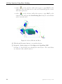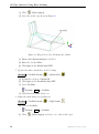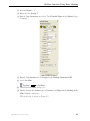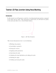
1
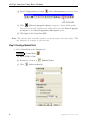
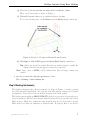
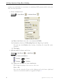
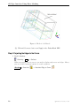
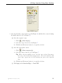
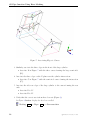
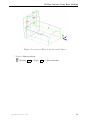
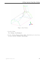
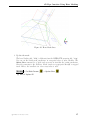
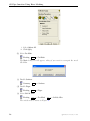
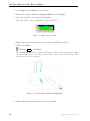
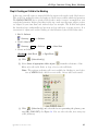
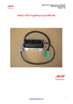
Tutorial: 3D Pipe Junction Using Hexa Meshing
Introduction
In this tutorial, you will generate a mesh for a three-dimensional pipe junction. After
checking the quality of the first mesh, you will create an O-Grid in the blocking to improve
mesh quality. Figure 1 shows the 3D pipe geometry.
Figure 1: 3D Pipe Geometry
This tutorial demonstrates how to do the following:
• Creating parts for geometry.
• Creating the material point.
• Blocking the geometry.
• Projecting edges to the curves.
• Moving the vertices.
• Generating the mesh.
• Checking the mesh quality.
• Creating an O-Grid in the blocking.
• Verifying and saving the mesh.
c ANSYS, Inc. February 11, 2010
1
3D Pipe Junction Using Hexa Meshing
Prerequisites
This tutorial assumes that you are familiar with the menu structure in ANSYS ICEM
CFD and that you have read about this functionality. Some of the steps in setup and the
procedure will not be shown explicitly.
For details about hexa mesh generation, refer to the Chapter, Hexa, in ANSYS ICEM
CFD user manual.
Conventions
Some of the basic conventions used in this tutorial are:
• The icon to the left of the text (here, Blocking) suggests that you have to select the
option from the display tree.
Blocking
• The arrow mark with the text LMB in the box the suggests that you have to click
the left-mouse button to enable or disable an option (here, Vertices).
LMB
−→ Vertices
• The arrow mark with the text RMB in the box the suggests that you have to click
the right-mouse button to enable or disable an option (here, Numbers).
RMB
−→ Numbers
For detailed information about GUI and text conventions, refer to the document, Getting
Started with ANSYS ICEM CFD.
Preparation
1. Download the ICEM hexa 3dpipe FILES.zip file from the ANSYS Customer Portal. It contains the necessary input geometry file (hexa 3dpipe.tin).
2. Start ANSYS ICEM CFD and open the geometry (hexa 3dpipe.tin).
File > Geometry > Open Geometry...
Step 1: Creating Parts
In the first two tutorials, the parts were already defined. For this and the remaining
tutorials, the initial geometry is contained in a single part. You will put the geometry
into different parts to define different boundary regions.
2
c ANSYS, Inc. February 11, 2010
3D Pipe Junction Using Hexa Meshing
1. Enable Surfaces under Geometry in the Model display control tree.
2. Select Create Part option in the display tree.
RMB
−→ Parts
LMB
−→ Create Part
3. Create a new part for the largest semi-cylinder.
(a) Enter CYL1 for Part in the Create Part DEZ.
(b) Retain the selection of
entities).
(Create Part by Selection) and click
(Select
The Select geometry selection toolbar will appear.
c ANSYS, Inc. February 11, 2010
3
3D Pipe Junction Using Hexa Meshing
(c) Disable Toggle selection of points
, Toggle selection of curves
, and
Toggle selection of bodies
(material region definition) to avoid the selection
of entities other than surfaces.
(d) Ensure to enable Toggle selection of surfaces
.
Note: Entity types can also be deactivated by disabling them in the Model
display control tree.
(e) Select the largest semi-cylinder.
(f) Click the middle-mouse button to accept the selection.
(g) Click Apply in the Create Part DEZ.
The new part CYL1 will be added to the Model display control tree (see Figure 2).
Figure 2: CYL1 in Model Display Control Tree
4. Similarly, create new parts for the smaller semi-cylinder (CYL2), cylinder ends (INL
and OUT), and symmetry planes (SYM). See Figure 3.
When in continuation mode after pressing the middle-mouse button or Apply, you
can type in a new Part name and continue to select the surface(s) without reinvoking the function.
4
c ANSYS, Inc. February 11, 2010
3D Pipe Junction Using Hexa Meshing
Figure 3: 3D Pipe Geometry and its Surface Parts
5. Create a new part comprising all the curves in the geometry.
(a) Enter CURVES for Part in the Create Part DEZ.
(b) Retain the selection of
entities).
(Create Part by Selection) and click
(c) Enable Toggle selection of curves
(d) Disable Toggle selection of surfaces
bar.
(e) Click
(Select
in the Select geometry selection toolbar.
in the Select geometry selection tool-
(Select all appropriate objects) or type a to select all the curves.
You need not click the middle-mouse button when using Select all appropriate
objects or Select all appropriate visible objects option.
(f) Click Apply in the Create Part DEZ.
6. Create a new part comprising all the points in the geometry.
(a) Enter POINTS for Part in the Create Part DEZ.
(b) Retain the selection of
entities).
(Create Part by Selection) and click
(c) Enable Toggle selection of points
c ANSYS, Inc. February 11, 2010
(Select
in the Select geometry selection toolbar.
5
3D Pipe Junction Using Hexa Meshing
(d) Disable Toggle selection of curves
(e) Click
in the Select geometry selection toolbar.
(Select all appropriate objects) or type a to select all the points.
You need not click the middle-mouse button when using the Select all appropriate objects or the Select all appropriate visible objects option.
(f) Click Apply in the Create Part DEZ.
Note: The selection logic is flexible and there are many ways to select the entities. This
step illustrates an example of selection logic.
Step 2: Creating a Material Point
1. Select Create Body in the Geometry tab.
Geometry > Create Body
(a) Enter FLUID for Part.
(b) Retain the selection of
(c) Click
6
(Material Point).
(Select location(s)).
c ANSYS, Inc. February 11, 2010
3D Pipe Junction Using Hexa Meshing
(d) Select two locations such that the midpoint lies within the volume.
These can be two points as shown in Figure 4.
(e) Click middle-mouse button to accept the selection of points.
To see the selected points, enable Points under the Model display control tree
Figure 4: Selection of Points for Material Point Creation
(f) Click Apply so that FLUID appears in Parts in Model display control tree.
Tip: Rotate the model to confirm that the new material point is within the
volume and does not just appear so from one perspective.
Note: Parts (such as GEOM) will be deleted when they no longer contain any
entities.
2. Save the geometry file (3d-pipe-geometry-1.tin).
File > Geometry > Save Geometry As...
Step 3: Blocking the Geometry
The blocking strategy for the 3D pipe geometry (as shown in Figure 3) involves creating
two blocks from the initial block—one each for each half cylinder, forming an L-shaped
configuration. You need to create an O-Grid to improve the mesh quality.
The blocking functionality in ANSYS ICEM CFD provides a projection based mesh generation environment. All block faces between different materials are projected to the closest
CAD surfaces. Block faces within the same material may also be associated to specific
CAD surfaces to allow for definition of internal walls. In general, there is no need to
c ANSYS, Inc. February 11, 2010
7
3D Pipe Junction Using Hexa Meshing
perform any individual face associations to underlying CAD geometry which reduces the
time for mesh generation.
1. Create an initial block.
Blocking > Create Block
> Initialize Blocks
(a) Ensure that Part is set to the correct material (FLUID).
(b) Retain the selection of 3D Bounding Box in the Type drop-down list.
You need not select Entities when creating a bounding box around the entire
geometry.
(c) Click Apply.
2. Split the initial block into sub-blocks.
Blocking > Split Block
> Split Block
(a) Enable Curves and Surfaces.
Geometry
LMB
−→ Curves
Geometry
LMB
−→ Surfaces
(b) Display the left view for better visualization.
The L-shaped topology is best seen in a side view.
View > Left
You can also select the X-axis in the display triad in the lower right hand
corner to re-orient the model as it appears in Figure 5.
8
c ANSYS, Inc. February 11, 2010
3D Pipe Junction Using Hexa Meshing
(c) Split the initial block vertically.
i. Click
(Select edge(s)) and select one of the horizontal edges.
ii. Position the new edge near the front end of the small cylinder.
iii. Click the middle-mouse button to accept the new position.
(d) Split the initial block horizontally.
i. Click
(Select edge(s)) and select one of the vertical edges.
ii. Position the new edge near the top of the large cylinder.
iii. Click the middle-mouse button to accept the new position.
Figure 5 shows the split block.
Figure 5: Geometry Showing Split Block Locations
3. Delete unnecessary upper block.
Blocking > Delete Block
(a) Click
(Select block(s)), select the block to be deleted as shown in Figure 6.
c ANSYS, Inc. February 11, 2010
9
3D Pipe Junction Using Hexa Meshing
Figure 6: Block to be Deleted
(b) Click middle-mouse button and Apply in the Delete Block DEZ.
Step 4: Projecting the Edges to the Curves
1. Disable Surfaces.
Geometry
LMB
−→ Surfaces
When associating edges to curves, you need to display only curves and edges. Hence,
you can disable unwanted entities to avoid confusion.
Blocking > Associate
10
> Associate Edge to Curve
c ANSYS, Inc. February 11, 2010
3D Pipe Junction Using Hexa Meshing
2. Associate the three edges at the top (A in Figure 7) with the three curves forming
the small semi-circle (A’ in Figure 7).
(a) Select the required edges.
i. Click
(Select edge(s)).
ii. Select the edges denoted by A in Figure 7.
iii. Click the middle-mouse button to accept the selection.
(b) Select the appropriate curves.
i. Click
(Select compcurve(s)).
ii. Select the curves denoted by A’ in Figure 7.
Tip: When selecting multiple curves, the first curve selected determines
the curve color of the final grouped curve. To avoid confusion with
green edges, experts try to avoid selecting the green curve segments
first.
iii. Click the middle-mouse button to accept the selection.
(c) Click Apply in the Associate Edge -> Curve DEZ.
c ANSYS, Inc. February 11, 2010
11
3D Pipe Junction Using Hexa Meshing
Figure 7: Associating Edges to Curves
3. Similarly, associate the three edges in the front of the large cylinder.
• Associate B in Figure 7 with the three curves forming the large semi-circle
(B’).
4. Associate the three edges on the Y-plane near the cylinder intersections.
• Associate C in Figure 7 with the semi-circle curve forming the intersection
(C’).
5. Associate the side rear edges of the large cylinder to the curves forming the rear
ends.
• Associate D to D’.
• Associate E to E’.
6. Verify that the correct associations have been set (Figure 8).
In Figure 8 Surfaces display has also been enabled.
Blocking
12
RMB
−→ Edges
LMB
−→ Show association
c ANSYS, Inc. February 11, 2010
3D Pipe Junction Using Hexa Meshing
Figure 8: Projection of Edges to the Associated Curves
7. Deselect Show association.
Blocking
RMB
c ANSYS, Inc. February 11, 2010
−→ Edges
LMB
−→ Show association
13
3D Pipe Junction Using Hexa Meshing
Step 5: Moving the Vertices
1. Move all the vertices onto the geometry.
Blocking > Associate
> Snap Project Vertices
(a) Retain the selection of All Visible for Vertex Select.
(b) Click Apply.
2. Manually move the vertices.
Blocking > Move Vertex
(a) Click
cylinder.
> Move Vertex
(Select vert(s)) and select one of the vertices in green on the smaller
(b) Move the vertex along the associated curve such that the edges along the
smaller cylinder are nearly equidistant.
Select the Vertex. Pressing the left-mouse button drag the vertex along the
curve.
(c) Similarly, move the other vertices to appropriate locations on the geometry
(Figure 9).
Note: To optimize mesh quality, the vertices should be spaced to minimize the
average deviation of the edges from the curve. To achieve the most even
distribution with this half cylinder case, place the vertices approximately
60 degrees apart (180◦ half circle/3 edges = 60◦ per edge.)
14
c ANSYS, Inc. February 11, 2010
3D Pipe Junction Using Hexa Meshing
Figure 9: Moved Vertices
3. Save the blocking.
File > Blocking > Save Blocking As...
4. Provide a filename (3D-pipe-geometry.blk) so that the file can be reloaded at a
later time, using File > Blocking > Open Blocking....
c ANSYS, Inc. February 11, 2010
15
3D Pipe Junction Using Hexa Meshing
Step 6: Generating the Mesh
For this model, you will set the sizes on the parts, rather than on individual surfaces or
curves.
1. Set the sizes on the parts to generate the mesh.
Mesh > Part Mesh Setup
(a) Left-click on max size.
The MAX SIZE dialog box will open.
(b) Enter 10 for max size.
(c) Click Accept.
(d) Decrease max size for CYL2 to 5.
(e) Enter 1 for height for CYL1 and CYL2.
(f) Enter 1.2 for height ratio for CYL1 and CYL2.
(g) Click Apply and Dismiss in the Part Mesh Setup dialog box.
2. Select Hexa Sizes (see Figure 10).
Geometry
RMB
−→ Surfaces
LMB
−→ Hexa Sizes
The “quad” along the surface represents the max size, the thickness represents the
height, while the number is the height ratio.
16
c ANSYS, Inc. February 11, 2010
3D Pipe Junction Using Hexa Meshing
Figure 10: Hexa Mesh Sizes
3. Update the mesh.
The hexa blocking file (.blk) is different from the ICEM CFD geometry file (.tin).
You can set the entity mesh parameters at any point before or after blocking. The
Update Sizes command is a quick and easy way to translate the entity parameters
from the geometry to the blocking. Mesh counts are propagated through a mapped
mesh. Hence, the smallest size across any index is used.
Blocking > Pre Mesh Params
> Update Sizes
(a) Enable Update All.
c ANSYS, Inc. February 11, 2010
17
3D Pipe Junction Using Hexa Meshing
i. Select Update All.
ii. Click Apply.
(b) Select Pre-Mesh.
Blocking
LMB
−→ Pre-Mesh
The Mesh dialog box will appear, asking if you want to recompute the mesh.
Click Yes.
(c) Disable Surfaces.
Geometry
LMB
−→ Surfaces
(d) Disable Edges.
Blocking
LMB
−→ Edges
(e) Select Solid & Wire.
Blocking
RMB
−→ Pre-Mesh
LMB
−→ Solid & Wire
The initial mesh is shown in Figure 11.
18
c ANSYS, Inc. February 11, 2010
3D Pipe Junction Using Hexa Meshing
Figure 11: Initial Mesh Display
Step 7: Checking the Mesh Quality
The major quality criteria for a hexa mesh are angle, determinant, and warpage. Refer
to the User’s Guide for details on the available quality measures.
Blocking > Pre-Mesh Quality Histograms
c ANSYS, Inc. February 11, 2010
19
3D Pipe Junction Using Hexa Meshing
1. Select Angle in the Criterion drop-down list.
2. Retain the default settings for Histogram Options and click Apply.
3. Select the worst two bars from the histogram.
The selected bars will be highlighted in pink (Figure 12).
Figure 12: Histogram of Angle
4. Right-click in the histogram window and ensure that Show is enabled.
5. Deselect Pre-Mesh.
Blocking
LMB
−→ Pre-Mesh
The highlighted elements are shown in Figure 13. Most of the bad elements (with
the worst angles) are on the block corners. This is due to the H-grid nature of the
mesh within a curved geometry.
Figure 13: Worst Quality Elements Highlighted
6. Right-click in the histogram window and select Done.
20
c ANSYS, Inc. February 11, 2010
3D Pipe Junction Using Hexa Meshing
Step 8: Creating an O-Grid in the Blocking
In this step, you will create an internal O-Grid to improve the angles in the block corners.
This is the best method for fixing bad angles in block corners within cylindrical geometry.
The ANSYS ICEM CFD has a specific O-Grid tool to make it easy to accomplish on even
complicated geometry. Before proceeding to this step, make sure that your surface vertices
are aligned as you want them and internal edges are straight. The O-Grid tool offsets
the boundary faces orthogonally and you may end up with twice as many vertices. It is
convenient to adjust your surface blocking to ideal locations before O-Grid than after.
1. Enable Surfaces.
Geometry
LMB
−→ Surfaces
2. Disable Hexa Sizes.
Geometry
RMB
−→ Surfaces
LMB
−→ Hexa Sizes
3. Create an O-Grid.
Blocking > Split Block
(a) Click
> Ogrid Block
(Select block(s)).
(b) Select Select all appropriate visible objects
from the selection tool bar.
Enter v for all visible blocks or drag a box to select all blocks.
Note: The option a indicating all is not available for blocking to avoid selection of VORFN blocks, which are not visible, but are still in the model.
(c) Click
(Select face(s)) and select the faces representing the planar geometry (INL, SYM, OUT). See Figure 14. You can also select the faces using any
of the following:
c ANSYS, Inc. February 11, 2010
21
3D Pipe Junction Using Hexa Meshing
• Select
in the selection toolbar that appears or type Shft-D on the
keyboard. This will allow you to select two diagonally opposite corners
that make up the face.
• Select
in the selection toolbar that appears or type Shft-P on the
keyboard. This will open the Select Blocking parts dialog box and will allow
you to select the faces.
Figure 14: Selected Blocks and Faces
(d) Click the middle-mouse button to accept the selection.
(e) Retain the default settings and click Apply in the Ogrid Block DEZ.
In Figure 15, the O-Grid passes through the selected faces. The radial blocks
are adjacent to the cylinder surfaces.
22
c ANSYS, Inc. February 11, 2010
3D Pipe Junction Using Hexa Meshing
Figure 15: Blocking with the O-Grid Structure
4. Modify the O-Grid.
Blocking > Edit Block
> Modify Ogrid
(a) Retain the selection of Rescale Ogrid in the Method drop-down list.
(b) Retain the selection of All Visible for Block Select.
c ANSYS, Inc. February 11, 2010
23
3D Pipe Junction Using Hexa Meshing
(c) Click
(Select edge(s)).
(d) Select the radial edge shown in Figure 16.
Figure 16: Edge Selected for Modifying the O-Grid
(e) Ensure that Absolute distance is disabled.
(f) Enter 0.5 for the Offset.
(g) Click Apply in the Modify Ogrid DEZ.
5. Update the surface mesh sizes on the blocking.
Blocking > Pre-Mesh Params
> Update Sizes
(a) Retain the selection of Update All.
(b) Click Apply in the Recalculate Sizes DEZ.
(c) Select Pre-Mesh.
Blocking
LMB
−→ Pre-Mesh
(d) Click Yes in the Mesh dialog box.
6. Refine the mesh using edge parameters.
Blocking > Pre-Mesh Params
> Edge Params
(a) Deselect Pre-Mesh.
Blocking
(b) Click
24
LMB
−→ Pre-Mesh
(Select edge(s)) and select one of the radial edges.
c ANSYS, Inc. February 11, 2010
3D Pipe Junction Using Hexa Meshing
(c) Increase Nodes to 7.
(d) Enter 0.2 for Spacing 1.
(e) Enable Copy Parameters and select To All Parallel Edges in the Method dropdown list.
(f) Enable Copy absolute and click Apply in the Meshing Parameters DEZ.
(g) Select Pre-Mesh.
Blocking
LMB
−→ Pre-Mesh
(h) Click Yes in the Mesh dialog box.
(i) Disable Curves and Surfaces under Geometry and Edges under Blocking in the
Model display control tree.
The final mesh is shown in Figure 17.
c ANSYS, Inc. February 11, 2010
25
3D Pipe Junction Using Hexa Meshing
Figure 17: The Final Mesh
Step 9: Verifying and Saving the Mesh
1. Check the mesh quality.
Blocking > Pre-Mesh Quality Histograms
(a) Select Angle in the Criterion drop-down list and click Apply.
You can see the improved mesh quality in the histogram.
(b) Select Determinant 2 × 2 × 2 in the Criterion drop-down list and click Apply.
2. Save the mesh in unstructured format.
Pre-Mesh Convert to Unstruct Mesh
26
c ANSYS, Inc. February 11, 2010
3D Pipe Junction Using Hexa Meshing
This saves the .uns file as the mesh in the working directory and automatically
loads it.
3. Save the project file (3D-pipe-geometry-final.prj).
File > Save Project As...
4. Exit the current session.
File > Exit
c ANSYS, Inc. February 11, 2010
27
3D Pipe Junction Using Hexa Meshing
28
c ANSYS, Inc. February 11, 2010