1
Eye3-VTracker – In Car Video System Specifications
Function & Technical Requirements Document
November, 2011
This document contains proprietary and copyrighted information subject to change without notice. The information
in this document shall not be duplicated, used, or disclosed in whole or in part outside of Eye3Data © 2006 - 2011.
Any distribution of this material without the written consent of Eye3Data is strictly prohibited.
Eye3-VTracker – In Car Video System Specifications
Table of Contents
1.
Introduction to EYE3-VTRACKER ........................................................................................ 3
2.
Components and Features ........................................................................................................ 3
2.1
System Recording Module and Mounting Assembly .......................................................... 3
2.2
Video and Audio DVR Features and Capabilities ............................................................... 3
2.3
Remote Connection and Download of Audio/Video data for Playback .............................. 4
2.4
Eye3-VTracker Storage and Other Accessories .................................................................. 4
3.
Installation & Environment Specifications.............................................................................. 5
4.
Playback Management ........................................................................................................... 10
4.1
Play Recordings ................................................................................................................. 10
4.2
Play Events......................................................................................................................... 11
5.
Eye3-VTracker Data Management Software ........................................................................ 11
5.1
Eye3-VTracker Analysis/Playback Software .................................................................... 11
5.2
Eye3-VTracker Remote Management Software ................................................................ 12
5.3
Eye3-VTracker Auto-Download Software ........................................................................ 12
5.4
Eye3-VTracker Central Management Software (CMS) .................................................... 13
5.5
Eye3-VTracker Management Reporting ............................................................................ 13
This document contains proprietary and copyrighted information subject to change without notice. The information
in this document shall not be duplicated, used, or disclosed in whole or in part outside of Eye3Data © 2006 - 2011.
Any distribution of this material without the written consent of Eye3Data is strictly prohibited.
Eye3-VTracker – In Car Video System Specifications
1.
Introduction to EYE3-VTRACKER
The Next Generation in Video Surveillance has arrived! Eye3Data's VTRACKER Digital Cruiser Video
Solution leverages state of the art Video Surveillance Technologies, with a true Solid State based
scalable architecture. The solution combines the power of GPS and Wireless technologies, all in a
compact and lightweight unit which is easy to install just about anywhere in the vehicle.
2.
Components and Features
2.1 System Recording Module and Mounting Assembly
a) Eye3-VTracker has been designed with an ultra-compact case, extremely low weight, high
temperature resistance and vibration resistant
b) The system runs on low voltage, low-current architecture suitable for mobile mounting (buses, cars,
vans, trucks, trains, etc.) or fixed locations
c) Quick release and removable recording module with tamperproof lock and secure controls.
d) Individual wire connections for Audio, Video, Power, Inputs/Outputs and accessory assemblies
e) 8 V~ 36 V DC, output 12V/3Amp regulated power for use with cameras, inputs/outputs and
accessory assemblies
f) Full support of NTSC or PAL video inputs and outputs, Audio channels
g) Communications supported through Build-in 3G/ EDGE/ CDMA, WIFI for wireless Transmission,
TCP/IP network interface and USB connection to PC’s
h) Handheld IR Controller with On-Screen Display (OSD) for all operations of Eye3-VTracker
i) Support Solid State SD card 8/16/32/64.
2.2 Video and Audio DVR Features and Capabilities
a)
Eye3-VTracker comes in 4 channels Video/Audio with H.264 Wireless Transfer, Dual streaming
transfer for each channel to provides the excellent recording performance.
b) 4 channels for video input, full-motion (30FPS/Camera) continuous or priority video recording and
live display (Support 1 channel Real-time D1, 4CH D1 at 12 fps/ 15fps.)
c) 4 channels of high-fidelity, digitally recorded, synchronized audio matched to 4 video channels
d) Continuous recording is available while in playback mode
e) User Friendly criteria to playback only events associated with the Video
f) Automatic timer to resume the live display if the unit is idle for a user defined timings
g) Linux 2.6 Embedded with H.264 video compression for high quality, low storage recording and
playback
h) Support powerful CMS (Central Monitoring System) for superior live view, GPS tracking, and alarm
information.
i)
User-Selectable settings for quality and audio record enable/disable for each video channel
j)
12v Power supply for multiple devices such as cameras, sensors, relays and other accessories
k) Selectable frame rate with event triggered burst recording speeds up to 30 FPS/Camera
l)
Total 19 Sensors (There are 8 alarms, Inertia, Over Speed, Low Speed, Motion, Camera Blind, Video
Loss, Ignition and 2 Relay sensor output) with selectable pre-alarm and post-alarm recording times
m) Dedicated Panic button provided to driver at all time for emergency alarms
n) TV output channel for live video and recorded video viewing
o) There are no buttons in the front of the unit to view, modify or erases the recorded data. All access is
provided using client software and with proper authentication.
p) The system includes a buffer memory for pre-event recording only. The buffer is programmable
through the system set-up menu to be capable of capturing up to 15 minutes of video prior to the
recorder being activated. The buffer time is adjustable.
This document contains proprietary and copyrighted information subject to change without notice. The information
in this document shall not be duplicated, used, or disclosed in whole or in part outside of Eye3Data © 2006 - 2011.
Any distribution of this material without the written consent of Eye3Data is strictly prohibited.
Eye3-VTracker – In Car Video System Specifications
q)
r)
The system shall have available a crash record activation feature that creates an EVENT when
involved in a collision. Please refer to Inertia Sensor Module as an accessory.
The system is able to protect recorded Events to insure that they are not recorded over or erased.
2.3 Remote Connection and Download of Audio/Video data for Playback
a)
b)
c)
d)
e)
f)
b)
Handheld Infra-Red controller with OSD for quick access to recorded video and setting menus
USB Connection for file transfer, PC-based file transfer and settings management
PC based client software for live viewing, playback video, playback events associated video and
downloading capabilities
Eye3-VTracker has the capability of downloading data in multiple methods and sizes
Video and Audio data are synchronized, stored in incremental packets of 15minutes, 30 minutes, 45
minutes or 60 minutes.
Video and Audio data can be downloaded in 4 ways :
i)
Wireless download if the vehicle is detected in a WIFI zone
ii)
Download of Event Data to a USB Thumb Drive
iii)
Download of audio/video data to a laptop
iv)
Removing cartridge from the docking station and carrying it to the administrative office
for download
Eye3-VTracker has the capability to enable a live view or playback audio/video inside the vehicle
using its Remote Management software (a laptop must exist in the vehicle to use this facility)
2.4 Eye3-VTracker Storage and Other Accessories
a) Eye3-VTracker can store both video and audio data on Solid State Secure Digital (SD) Card
technology with capacities ranging up to 64 Gigabytes.
b) Eye3-VTracker Removable SD-Card. The Eye3-VTracker unit comes with a removable SD-Card
storage which is locked into the main unit, prevents removal of the actual SD-Card except by
authorized individuals with a key. A GPS version of the unit is required to take advantage of the GPS
tracking features of the Eye3-VTracker.
c) Lock Box. The entire Eye3-VTracker unit is stored neatly inside a keyed lock box. The Lock box is a
ventilated Steel case that prevents unauthorized access to the Eye3-VTracker.
d) Inertia Sensor. The Eye3-VTracker unit can be connected to an Inertia Sensor Module. This external
device monitors the X, Y, Z co-ordinates of the bus. Sensitivity levels of the X, Y, Z co-ordinates are
pre-established. The unit senses deviations to the X, Y, Z co-ordinates and creates Alarms/Event
notifications of drastic changes to the X, Y, Z co-ordinates. The Inertia Sensor module is used to
monitor Driver behavior, prior to the time of incident. The Inertia Sensor module is used to monitor
Driver behavior, prior to the time of incident. Inertia Sensor module can be use to capture outside
temperature environment with Low and High Temperature events.
e) Remote Control Head is an optional accessory that is primarily used by Law Enforcement and other
Emergency type vehicles along with an LCD display. The primary purpose of the Remote Control
head is to allow the operator to view live and preview earlier recordings.
f)
The Eye3-VTracker has (1) USB port in the front of the unit, to download event data directly to a
laptop or to upload revisions to the firmware on the Mobile unit.
This document contains proprietary and copyrighted information subject to change without notice. The information
in this document shall not be duplicated, used, or disclosed in whole or in part outside of Eye3Data © 2006 - 2011.
Any distribution of this material without the written consent of Eye3Data is strictly prohibited.
Eye3-VTracker – In Car Video System Specifications
g) A build-in WIFI Module (optional) is available and can be installed to enable wireless connectivity
with remote locations. The WIFI module will be effective only while the bus is in a WIFI Hot zone. A
Remote Management Software (RMS) will be required on the Remote-end to establish connectivity
with the vehicle and obtain a live view of cameras (Remote Management Software details will be
provided later). The WIFI 802.11g module will also be used to wirelessly download video and/or
events data to a remote AUTO-DOWNLOAD Server. This is an optional accessory and may be
replaced by a generic Wireless-Router available in any electronics store.
Eye3-VTracker can also be monitored remotely using build-in 3G and CDMA networks provided by
Verizon, Sprint and AT&T. A static IP address is required to facilitate this advanced feature.
h) An external Wireless G-Router for Mobile Broadband can be attached to the Eye3-VTracker unit to
allow remote viewing of the cameras.
3.
Installation & Environment Specifications
a)
b)
c)
d)
e)
Eye3-VTracker uses only regulated 12-volt DC or 24-volt DC (2 ~ 3 Amps) certified power supply
for installation in vehicles. The unit can handle power ranges from 7v ~ 28v DC.
Do not attach powered input leads that exceed 12-volt DC at 1.5 Amps OR 5-volt DC at 1.5 Amps
supply on any one connection.
Eye3-VTracker unit may be operated in a totally sealed enclosure with no cooling airflow, ensure
that the operating temperature of the unit does not exceed 140°F (60°C) or that the standing
temperature does not exceed 175°F (80°C). The minimum operating temperature for the Eye3VTracker product is -20°F (-28°C). If the minimum temperature is expected to exceed, connect an
auxiliary heat source.
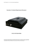
Eye3-VTracker Dimensions:
Main Unit
Height
Width
Depth
Weight
2.1 “
5.2 “
6.6 “
2.4 lb
General Installation Specifications
Power:
Moisture:
It is recommended that the unit be connected to the vehicle ignition. Battery power
is used only when the vehicle is running. The unit could drain any vehicle battery
over time if the ignition is not turned off or if the system is not powered properly to
the vehicle power panel.
Connection:
Connect only to appropriate power supply and ensure proper
grounding of the circuit. Use of Relays is encouraged for power supply and wired
sensors to prevent fluctuations in power supply which could adversely affect the
Eye3-VTracker mobile unit.
Protect unit and connections from environmental sources of moisture
and liquid spills.
This document contains proprietary and copyrighted information subject to change without notice. The information
in this document shall not be duplicated, used, or disclosed in whole or in part outside of Eye3Data © 2006 - 2011.
Any distribution of this material without the written consent of Eye3Data is strictly prohibited.
Eye3-VTracker – In Car Video System Specifications
Temp:
Ventilation:
Vibration:
Clearance:
Wiring:
Access:
Injury:
Do not install where unit temperature will exceed F140°F (60°C), fall
below -20°F (-28°C) or store the unit where temperatures rise above
175°F (80°C). Avoid direct exposure to sunlight.
Provide sufficient ventilation with a minimum of 6 inches cooling
clearance to ensure proper operating temperature for the unit.
If necessary, provide additional shock mounting to prevent damage and
wear by excessive vibration.
Front clearance of 16.5 cm or 6.49 inch is required to slide the recording module
from the mounting assembly.
Install where mounting assembly wires have sufficient clearance and will not be
crimped or subject to wire insulation damages due to vibration.
Secure the Eye3-VTracker unit so that passengers or drivers cannot
tamper or damage the unit, cameras, wires or other accessories. Do not
mount where access to any other vehicle component will be restricted.
Install the unit, cameras, accessories and wires so that no injuries can be caused
through impact with equipment during vehicle operation. Ensure that all
transportation regulations are followed to avoid passenger injury should they come
in contact with the installed equipment.
This document contains proprietary and copyrighted information subject to change without notice. The information
in this document shall not be duplicated, used, or disclosed in whole or in part outside of Eye3Data © 2006 - 2011.
Any distribution of this material without the written consent of Eye3Data is strictly prohibited.
Eye3-VTracker – In Car Video System Specifications
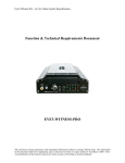
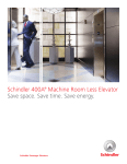
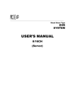
f)
Eye3-VTracker Technical Schematic Layout
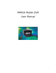
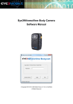
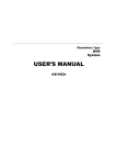
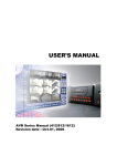
g)
Eye3-VTracker System Tree and Default Settings
This document contains proprietary and copyrighted information subject to change without notice. The information
in this document shall not be duplicated, used, or disclosed in whole or in part outside of Eye3Data © 2006 - 2011.
Any distribution of this material without the written consent of Eye3Data is strictly prohibited.
Eye3-VTracker – In Car Video System Specifications
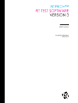
Options
System
Date / Time
Date Mode
Weekday Start
Weekday End
Time Sync
Daylight Time
General
Unit ID
Record File Size
Idle Time
Time Switch
Video Type
Audible Alarm
Priority Record
HDD O/W
Network
IP Address
Subnet Mask
Gateway
Security
Register Info
Company Name
Vehicle Number
Driver Name
Device Info
Camera
Camera 1
Camera 2
Camera 3
Camera 4
Camera Num
Rate (FPS)
Resolution
Time Insert
Schedule
Event Setup
Sensor 1
Sensor 2
Sensor 3
Sensor 4
Sensor 5
Sensor 6
Sensor 7
Sensor 8
X Sensitive (g)
Y Sensitive (g)
Z Sensitive (g)
Speed Source
Default Setting
Current date and time
MM/DD/YY
Monday
Friday
NO
NO
000
15
100
OFF
NTSC
NO (for all)
Disable
YES
192.168.0.100
255.255.255.0
192.168.0.1
Yes
XYZ
123
ABC
001
Label = No Label
Label = No Label
Label = No Label
Label = No Label
04
30
CIF
ON
Quality = 1
Quality = 1
Quality = 1
Quality = 1
Audio = Yes
Audio = Yes
Audio = Yes
Audio = Yes
ON, Everyday: 00:00 – 23:59
NO or NC depending on usage & Configuration
NO or NC depending on usage & Configuration
NO or NC depending on usage & Configuration
NO or NC depending on usage & Configuration
NO or NC depending on usage & Configuration
NO or NC depending on usage & Configuration
NO or NC depending on usage & Configuration
NO or NC depending on usage & Configuration
0.2
0.2
0.2
GPS if available or Odometer
This document contains proprietary and copyrighted information subject to change without notice. The information
in this document shall not be duplicated, used, or disclosed in whole or in part outside of Eye3Data © 2006 - 2011.
Any distribution of this material without the written consent of Eye3Data is strictly prohibited.
Eye3-VTracker – In Car Video System Specifications
h)
Eye3-VTracker GPS Functionality
Eye3-VTracker GPS features are available only when the system is ordered with GPS. The GPS
connection port is located on the rear of the Docking Station. To enable the GPS features, a GPS
antenna (either generic or provided along with GPS unit) needs to be connected to the GPS port.
Once connected, and placed outside the vehicle facing towards the sky, the GPS unit is activated.
GPS data appearing on the screen is limited to the following:
i. N for Longitude
ii. W for Latitude
iii. Vehicle Speed
i)
Additionally, GPS also tracks the values of the GPS (N, W and Speed) which is embedded on the video.
This information can be translated using any mapping software to display the true location of the
vehicle. (Mapping software needs to be purchased separately and is not provided with the Eye3VTracker unit).
Eye3-VTracker PTZ Functionality
The Eye3-VTracker can support PTZ (Pan/Tilt/Zoom) cameras and control via the IR Remote
control via the RS-485/RS422 port located on the rear of the Docking Station.
j)
a) All 4 or 8 channels can have PTZ cameras
b) Supports 16 protocols; which include Pelco-D, Pelco-P, DSCP, FastDome, PIH 1016, PIH 1017
and Pelco06 to Pelco15. If a corresponding protocol is not found in this list, please contact us
directly. We can provide technical support to add the missing protocol if PTZ details are
provided.
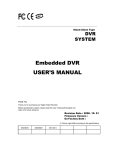
Eye3-VTracker Mini-LED Display
On most occasions the Eye3-VTracker unit is installed either in the overhead panel or underneath
the driver seat. In both instances the unit is not visible to the driver. Eye3-VTracker Mini-LED
Display is installed on the dash-board of the vehicle, providing bus driver information related to the
vitals of the Eye3-VTracker Unit. The unit consists of red and green LED’s for Power, HDD, Record,
Video Loss, Audio Loss and Alarm. The unit is always visible to the driver and is able to provide
customers advanced notice if the system is not functioning properly.
4.
Playback Management
The Eye3-VTracker has a very simple and easy to use Playback Management System. The system
plays back recordings in 2 ways:
a)
b)
4.1
View list of recordings, select the date/time of recording and Press START
View list of Events in the Event Folder and Select Event to be played. The system will play the
pre-event recording (up to 15 seconds) and then the post-recording (up to 300 seconds).
Play Recordings
a)
The system allows users to enter specific dates for the playback. The oldest record time is a
quick reference for the oldest recording available on the unit. Enter the date and time using the
handheld IR Controller and press START.\
This document contains proprietary and copyrighted information subject to change without notice. The information
in this document shall not be duplicated, used, or disclosed in whole or in part outside of Eye3Data © 2006 - 2011.
Any distribution of this material without the written consent of Eye3Data is strictly prohibited.
Eye3-VTracker – In Car Video System Specifications
b)
A calendar function is also available which displays in yellow, days for which recording is
available. Blue color indicates no recording.
c)
While the selected Video is playing back, user can select the camera number (1,2, 3 or 4) on
the remote menu or the control panel to jump to the specific time in the clip.
d)
The system is capable of downloading data to a CF card while in playback mode. The data
file created on the CF Card is a .M65 format and can be opened in the Analysis software
e)
While the video is playing, the system has the capability to display associated text on the
channel. The following text can be displayed on the screen :
I.
II.
III.
IV.
V.
VI.
VII.
4.2
Driver ID
Vehicle ID
Camera Label
GPS Coordinates
Date
Time
Sensor label
Play Events
a)
The system allows users to select from a display of sensor triggered events. The user can
scroll down, find the event to play and press ENTER.
b)
The Event display screen would display the event #, date the event was created, time the
event was created and Sensor Type or what triggered the Event.
c)
While the video is playing, the system has the capability to display associated text on the
channel. The following text can be displayed on the screen :
1. Driver ID
2. Vehicle ID
3. Camera Label
4. GPS Coordinates
5. Date
6. Time
7. Sensor label
** The same criteria will be used later in the Query & Reporting section. Users will be able to
query/extract video and audio data based on the criteria mentioned above.
5.
Eye3-VTracker Data Management Software
The Eye3-VTracker system is accompanied with an extensive list of applications to Download, View
and Analyze Video and Event data and produce Ad-Hoc Management Reports. Following is a list of
applications packaged with the Eye3-VTracker:
5.1
Eye3-VTracker Analysis/Playback Software
This document contains proprietary and copyrighted information subject to change without notice. The information
in this document shall not be duplicated, used, or disclosed in whole or in part outside of Eye3Data © 2006 - 2011.
Any distribution of this material without the written consent of Eye3Data is strictly prohibited.
Eye3-VTracker – In Car Video System Specifications
The Analysis software is a dashboard driven application that allows the user to analyze a
recording clip downloaded by either of the 4 methods of download. Depending on the type
of download, the unit generates either a .CAR or .M65 or .p10, p11, .p12 or .p13 file. Any of
these files may be opened in the Analysis software to get a view of the Video, Audio, GPS
location, Speed, Event Data, Inertia Sensor data etc.
The Eye3-VTracker unit can be configured to record data in increments of 15minutes, 30
minutes or 45 minutes. When data is downloaded using either of the 4 methods of
download, the data file contains the pre-defined minutes of video data. It is recommended to
set the Eye3-VTracker to create data in 15 minute packets.
The Analysis playback software works with different kinds of mapping software to display
the vehicle location. The Google version of the software requires an internet connection and
enables the customer to track the vehicle across county, city and state lines. The Google
maps version is licensed and available at an incremental cost.
5.2
Eye3-VTracker Remote Management Software
The Remote Management Software provides the customer the ability to remotely view
cameras inside the bus over a Wireless connection. To access the Remote management
software, the bus either has to be in a WIFI network or a cellular network. To access
video/audio data via a Cellular network, a separate WIFI card from either SPRINT OR
VERIZON is required.
The remote management software has the ability to view up to 16 buses in one single
session, this could equate to 1 camera each from 16 buses or a combination of cameras from
a number of buses. Each bus needs to have a unique static IP address, which needs to be
configured on RMS.
The Remote Management software provides the capability to change the configuration on
the bus/vehicle system remotely, search for video/audio data on the bus and download it to
a local machine for viewing locally. More details about the software can be found on the RMS
User Manual.
5.3
Eye3-VTracker Auto-Download Software
The Auto-download server is installed at the facility where audio/video data needs to be
captured. The Auto-download server is an advanced application that can manage, monitor
and connect to multiple vehicle units concurrently (depending on network bandwidth).
While the connection is established, the server would trigger a scheduled download of Video
and/or events from the vehicle to the Auto-download server.
The Auto-download method of download requires a ROUTER to be installed in each vehicle
and either a one or more ACCESS points installed in the administrative building. When a
vehicle arrives at the location/garage and turns the ignition off, a wireless connection is
established between the vehicle and the Access Point. Depending on the auto-download
server configuration, the bus can download either “ONLY EVENTS” or “VIDEO and EVENTS”
to the auto-download server. Typically, customers are interested in downloading only
“EVENTS” taking into consideration the network bandwidth available on the wireless
network.
This document contains proprietary and copyrighted information subject to change without notice. The information
in this document shall not be duplicated, used, or disclosed in whole or in part outside of Eye3Data © 2006 - 2011.
Any distribution of this material without the written consent of Eye3Data is strictly prohibited.
Eye3-VTracker – In Car Video System Specifications
Each Vehicle that arrives is added into a queue and video data (if any events are available) is
downloaded on a FIFO ( First come first serve basis).
5.4
Eye3-VTracker Central Management Software (CMS)
This software is primarily used by a central monitoring facility to view live video or playback
from a remote location, typically via a wireless network. The CMS software allows the
vehicle and the administration to communicate via SMS or Instant Video Alarm Notifications.
CMS include remotely live view, record file download, local recording, GPS tracking and
playback, strong log system and vehicle group management.
5.5
Eye3-VTracker Management Reporting
Our Eye3 VTracker, while acting as a fully functional digital video recorder, also has the capability to
record a wide array of sensor and event data. These special data sets, or metadata, are embedded in our
secure proprietary video format in two ways. Portions of this metadata are recorded in the 50 byte video
filename, while the other are pulled out by our codec processing engine. Below is an example of a decoded
file name:
File 1 :: 0000000000000000-100812-041507-043007-12u212000000.264
Channel Name/Driver Name: 0000000000000000
Clip Date: 08/12/10
Clip Start Time: 04:15:07 am
Clip End Time: 04:30:07 am
Type: NTSC
Resolution: CIF
Frames Per Second: 30
Recording Mode: Alarm Recording
Protected: Yes
Channel: 2
Global UID: {27A11E23-C30E-4EBF-AE8F-8CF53AEF9004}
The channel name and driver name sections are defined in the DVR and are customizable. These are
hard coded into the DVR via a firmware menu system. The data and time stamps are generated via the
internal clock of the DVR. This clock can be synchronized via GPS or NTP (NTP recommended for Delaware
State Police application). The following fields freeing to the video data is also derived from the DVR’s
configuration. As you can see this particular file was generated through channel (camera) 2 at 30 frames per
second and using event based recording.
Once the file is generated, the DVR acts as the active storage device for vehicle, when the vehicle
returns to the depot or yard, the stored files are transferred wirelessly to the Auto Download/FTP Server.
The Auto Download Server stores the files in a tree-style directory structure as follows:
<drive letter>:/<storage location>/<vehicle id>/<date>/<channel>/<file_name.nvr>
Incomplete downloads are automatically flagged and restarted when the vehicle returns the next time.
This ensures complete data integrity even in the case of an emergency or shortened down time.
Our Auto Download Server handles the job of extracting the video data and saving it to a central
server, while an FTP routine handles extraction of log and metadata files and places in the same location with
This document contains proprietary and copyrighted information subject to change without notice. The information
in this document shall not be duplicated, used, or disclosed in whole or in part outside of Eye3Data © 2006 - 2011.
Any distribution of this material without the written consent of Eye3Data is strictly prohibited.
Eye3-VTracker – In Car Video System Specifications
respect to device/vehicle. Each device has its own folder containing video data and the unparsed log and
metadata files. Our Data Management Engine takes control at this point.
When new files are introduced to the system, our Data Management Engine examines new
information, processes the data, and inserts it into an SQL database. This database contains several tables
including vehicle information, driver information, device information, metadata information, video data
information and other calculated fields.
SQL Database contains the following tables:
Vehicle
Driver
Device
Data
vehicle_id, make, model, year, plate_num, etc.
driver_id, first, last, dob, contact_info_fields, hire_date, etc.
device_id, type, accessories (binary yes/no fields), last_download
record_guid, vehicle_id, driver_id, device_id, meta_data_fields [gps, inertia, temp, etc],
calculated_fields, time_stamp, video_index.
Notes
From these tables, our front end can query the database by any combination of columns. For
instance you can generate a report about all the male drivers who were active between 12am and 1am. From
this report you will see distance traveled, idle time, number of events on each sensor (brakes, meter, etc) as
well as calculated inertia statistics and projected revenue. From that report you can then view the video
corollary to the resulting dataset. There are of course report templates for things like shift statistics,
productivity, maintenance projections, etc. You will also have access to each drivers profile and able to make
notes regarding any of the collected data.
For further details on the RMS and Auto-download configurations, please contact our Technical
support hot line at (513) 770-0550.
This document contains proprietary and copyrighted information subject to change without notice. The information
in this document shall not be duplicated, used, or disclosed in whole or in part outside of Eye3Data © 2006 - 2011.
Any distribution of this material without the written consent of Eye3Data is strictly prohibited.