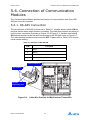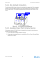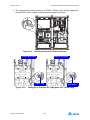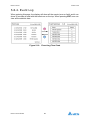
1
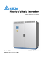
PhotoVoltaic Inverter RPI-C500 PV Inverter Version: 1.0.0 Modified: May 27, 2013 2:19 pm Installation Reference TABLE OF CONTENTS TABLE OF CONTENTS 1. Introduction 1 1.1. About This Manual . . . . . . . . . . . . . . . . . . . . . . . . . . . . . . . . . . . . 1 1.2. Valid Models. . . . . . . . . . . . . . . . . . . . . . . . . . . . . . . . . . . . . . . . . 1 1.3. Target Group . . . . . . . . . . . . . . . . . . . . . . . . . . . . . . . . . . . . . . . . 1 2. Safety 2 2.1. System Usage . . . . . . . . . . . . . . . . . . . . . . . . . . . . . . . . . . . . . . . 2 2.2. Disconnecting. . . . . . . . . . . . . . . . . . . . . . . . . . . . . . . . . . . . . . . . 2 3. Product Overview 4 3.1. Product Description . . . . . . . . . . . . . . . . . . . . . . . . . . . . . . . . . . . 4 3.2. Product View . . . . . . . . . . . . . . . . . . . . . . . . . . . . . . . . . . . . . . . . 4 3.2.1. Exterior Front View ................................................................. 4 3.2.2. Exterior Triangle View............................................................. 5 3.2.3. Interior Front View .................................................................. 6 3.3. Features . . . . . . . . . . . . . . . . . . . . . . . . . . . . . . . . . . . . . . . . . . . . 6 3.4. Identify the Inverter. . . . . . . . . . . . . . . . . . . . . . . . . . . . . . . . . . . . 7 4. Transportation 8 4.1. Delivery Options and Recommended Vehicle . . . . . . . . . . . . . . . 8 4.2. Using a Forklift . . . . . . . . . . . . . . . . . . . . . . . . . . . . . . . . . . . . . . . 8 4.3. Using a Crane . . . . . . . . . . . . . . . . . . . . . . . . . . . . . . . . . . . . . . 10 4.4. Package Contents . . . . . . . . . . . . . . . . . . . . . . . . . . . . . . . . . . . 11 4.5. Installation Site Requirements . . . . . . . . . . . . . . . . . . . . . . . . . . 12 4.5.1. Site Space ............................................................................ 12 INSTALLATION MANUAL I TABLE OF CONTENTS 5. Installation 13 5.1. Preparing the Installation Site . . . . . . . . . . . . . . . . . . . . . . . . . . 13 5.1.1. Building a base ..................................................................... 13 5.1.2. Using the ground as a base.................................................. 13 5.2. Recommended Tools . . . . . . . . . . . . . . . . . . . . . . . . . . . . . . . . . 14 5.3. DC Connection . . . . . . . . . . . . . . . . . . . . . . . . . . . . . . . . . . . . . . 14 5.4. AC Connection . . . . . . . . . . . . . . . . . . . . . . . . . . . . . . . . . . . . . . 15 5.5. PE Connection . . . . . . . . . . . . . . . . . . . . . . . . . . . . . . . . . . . . . . 16 5.6. Connection of Communication Modules. . . . . . . . . . . . . . . . . . . 17 5.6.1. RS-485 Connection .............................................................. 17 5.6.2. Dry Contact Connection........................................................ 19 5.6.3. Auxiliary Power from External Source .................................. 19 5.7. First Time Powering Up . . . . . . . . . . . . . . . . . . . . . . . . . . . . . . . 21 5.7.1. Before Powering Up.............................................................. 21 5.7.2. Powering Up the Inverter and Self-test................................. 21 5.8. LCD Flowchart . . . . . . . . . . . . . . . . . . . . . . . . . . . . . . . . . . . . . . 23 5.8.1. Home Page........................................................................... 23 5.8.2. Power Meter ......................................................................... 24 5.8.3. Energy Log ........................................................................... 24 5.8.4. Event Log.............................................................................. 25 5.8.5. Operation Data ..................................................................... 26 5.8.6. Inverter Information............................................................... 27 5.8.7. Settings................................................................................. 27 5.8.7.1. Personal Settings ........................................................... 28 5.8.7.2. Coefficient Settings ........................................................ 28 5.8.7.3. Install Settings................................................................ 29 INSTALLATION MANUAL II TABLE OF CONTENTS 6. Troubleshooting 32 6.1. Measurement Index . . . . . . . . . . . . . . . . . . . . . . . . . . . . . . . . . . 32 6.2. Error Message and Troubleshooting . . . . . . . . . . . . . . . . . . . . . 36 7. Maintenance 41 7.1. Replacing components. . . . . . . . . . . . . . . . . . . . . . . . . . . . . . . . 41 7.1.1. Replacing a Fan Module....................................................... 41 7.1.2. Replacing an Air Filter .......................................................... 44 Appedix A. Technical Data 46 Appedix B. Contact Information 50 INSTALLATION MANUAL III CONVENTIONS Conventions General Conventions The following conventions are used in this manual: Example: Indicates information used to demonstrate or explain an associated concept. Note: Indicates additional information that is relevant to the current process or procedure. ! ! WARNING! Warning information appears before the text it references to emphasize that the content may prevent damage to the device or equipment. CAUTION! CAUTIONS APPEAR BEFORE THE TEXT IT REFERENCES. CAUTIONS APPEAR IN CAPITAL LETTERS TO EMPHASIZE THAT THE MESSAGE CONTAINS VITAL HEALTH AND SAFETY INFORMATION. Typographical Conventions The following typographical conventions are used in this document: Italics Indicates denotes references to other titles, directories, files, paths, and/or programs. Screen Display width Indicates computer output shown on a computer screen, including menus, prompts, responses to input, and error messages. Bold type Indicates keyboard keys that are pressed by the user. INSTALLATION REFERENCE IV COPYRIGHT Copyright The ownership and all intellectual property rights of this Installation Reference (this “Manual”), including but not limited to the content, data and figures contained herein are vested by Delta Electronics, Inc. (“Delta”). The Manual can only be applied to operation or use of the product. Any disposition, duplication, dissemination, reproduction, modification, translation, extraction or any other usage to the Manual is prohibited without obtaining Delta’s prior written permission. As the product will be developed and improved continuously, Delta may modify or update the Manual from time to time without any notice. Delta will do its best efforts to keep the Manual updated and maintain the accuracy of the Manual. Delta disclaims any kinds or forms of warranty, guarantee or undertaking, either expressly or implicitly, including but not limited to the completeness, accuracy, non-infringement, merchantability or fitness for particular purpose or usage. Copyright © 2013 Delta Electronics, Inc. All Rights Reserved. INSTALLATION REFERENCE V INTRODUCTION ABOUT THIS MANUAL 1. Introduction 1.1. About This Manual This manual provides the detail information of specification, installation procedures and all related function setting about the RPI-C500 PV Inverter. Installation technicians must be well-trained and qualified for installing solar system and must follow all the safety instruction and installation procedures. 1.2. Valid Models This user manual describes the installation procedures, maintenance, technical data and safety instruction of the following solar inverter models under Delta brand. RPI-C500 PV Inverter 1.3. Target Group The guidelines in this manual provide instructions for a person who is well training and skillful for the installation of the central inverter. INSTALLATION GUIDE 1 SAFETY SYSTEM USAGE 2. Safety 2.1. System Usage See the system usage in the following diagram: Public Grid PV Array 3Ph DC Distribution box (3 Phase/N/PE) AC Distribution box 3 Phase Transformer Figure 2-1. System Usage 2.2. Disconnecting Isolation of the device must always occur under load-free conditions. ! CAUTION! RISK OF LETHAL ELECTRIC SHOCK. It is admitted to work on the PV Inverter only after switching the relative power sources. The VDE regulations must be followed: Disconnect Ensure that the device cannot be reconnected Ensure that no voltage is present Ground and short-circuit the unit if necessary (not on the DC side) If necessary, cover or shield any adjacent live components The following power sources must be isolated: Grid voltage for grid feeding Grid voltage for internal power supply (optional) DC voltage from the photovoltaic generator Simply switching off the main AC and DC switches is not sufficient to ensure proper isolation of the device. The main switches only separate the power circuit from the grid and the photovoltaic generator. ! CAUTION! RISK OF LETHAL ELECTRIC SHOCK. Dangerous accidental-contact voltages can be present in the PV Inverter even when the main AC and DC switches are switched off! Wait at least 5 minutes after switching off the PV Inverter. INSTALLATION GUIDE 2 SAFETY DISCONNECTING The DC voltage is isolated using the internal or external DC input fuses, or using an external circuit breaker if present. Isolation by removing the DC input fuses must occur under load-free conditions. The device contains capacitors on the AC and DC sides that must discharge once the device has been switched off. After switching off, dangerous accidental-contact voltages remain within the device for several minutes. If there is a fault in the device, these voltages may also be present for a longer period of time. Wait at least 5 minutes after switching off the device before opening the device. ! CAUTION! RISK OF LETHAL ELECTRIC SHOCK. Dangerous accidental-contact voltages can be present in the PV Inverter even when the main AC and DC switches are switched off! Wait at least 5 minutes after switching off the PV Inverter. INSTALLATION GUIDE 3 PRODUCT OVERVIEW PRODUCT DESCRIPTION 3. Product Overview 3.1. Product Description The Delta RPI inverter models include the RPI-C500. It is manufactured to meet high standards of quality and to maximize the yield of every solar plant (up to 98.5% efficiency). The RPI series include a IP-54 protection level enclosure and corrosion resistant features to ensure the protection of the inverter within an indoor or outdoor environment. 3.2. Product View 3.2.1. Exterior Front View Air Outlets LCD/LED Display Buttons Emergency Power Off (EPO) Figure 3-1. Exterior Front View INSTALLATION MANUAL 4 PRODUCT OVERVIEW EXTERIOR TRIANGLE VIEW 3.2.2. Exterior Triangle View Air Inlet Figure 3-2. INSTALLATION MANUAL Exterior Rear View 5 PRODUCT OVERVIEW INTERIOR FRONT VIEW 3.2.3. Interior Front View AC Terminals DC Terminals AC Surge Arrester AC Surge Arrester / Fuse Holder Net Wire Location GND Wire Location Figure 3-3. Interior Front View 3.3. Features The following are important features of the product(s) described in this manual: High efficiency, peak 98.5%, EUR 98.0% 3 Phase (3 Lines + PE) 500kVA solar inverter Wide input range (450-1000Vdc) Wide MPPT range (450-820Vdc) 1 MPP Trackers 5” Graphic LCD display (Adjustable contrast & brightness) IP-54 protective level (electrics) INSTALLATION MANUAL 6 PRODUCT OVERVIEW IDENTIFY THE INVERTER 3.4. Identify the Inverter Please refer to the following image for identifying the inverter. Figure 3-4. INSTALLATION MANUAL Inverter Identification 7 TRANSPORTATION DELIVERY OPTIONS AND RECOMMENDED VEHICLE 4. Transportation 4.1. Delivery Options and Recommended Vehicle Any equipment used for the transport of the central inverter must be suitable for the weight of the central inverter. The following equipment can be used for the transport of the central inverter: Forklift or crane (Recommended) Hoisting steel cables Hoisting hooks Steel rings 4.2. Using a Forklift To move the central inverter using a forklift: 1. Place the forks of the forklift under the unit. Figure 4-1. INSTALLATION GUIDE Moving the Central Inverter 8 TRANSPORTATION USING A FORKLIFT 2. Move the inverter to the installation base. The steps to install the inverter on the base depend on whether the unit is packed in a shipping crate: If the unit is not packed in a shipping crate, place it directly on the installation base. If the unit is packed in a shipping crate, follow these steps: a. Using a claw hammer or pry bar, remove the crate's wood top and side panels. b. Remove the central inverter anchor hardware that attaches it to the shipping pallet. Figure 4-2. Unpacking the Shipping Crate c. Remove the central inverter from the pallet and place it on the installation base. Figure 4-3. INSTALLATION GUIDE Removing the Central Inverter from the Pallet 9 TRANSPORTATION USING A CRANE 4.3. Using a Crane To move the central inverter using a crane: 1. Move the inverter to the installation base. The steps to install the inverter on the base depend on whether the unit is packed in a shipping crate: If the unit is packed in a shipping crate, follow these steps: a. Using a claw hammer or pry bar, remove the crate's wood top and side panels. b. Remove the central inverter anchor hardware that attaches it to the shipping pallet. Figure 4-4. Unpacking the Shipping Crate 2. Remove the top cover of the inverter. Figure 4-5. INSTALLATION GUIDE Removing the Inverter’s Top Cover 10 TRANSPORTATION PACKAGE CONTENTS 3. Attach the hoisting hooks and cables to the steel rings on the inverter. Crane hook Steel ring Hoisting hook Figure 4-6. Attaching the Hoisting Cables 4. Attach the crane hook to the steel ring on the hoisting cables. 5. Place the inverter on the installation base. 6. Remove the hoisting cables. 4.4. Package Contents Table 4-1: Package Content Object Qty Description Central Inverter 1 RPI-C500 PV Inverter Installation Manual 1 The Instruction to provide the information of safety, Installation, specification, etc. Key 2 Open/Close the door of the inverter Cable Gland 22 Prevent dust and water via cable INSTALLATION GUIDE 11 TRANSPORTATION INSTALLATION SITE REQUIREMENTS 4.5. Installation Site Requirements 4.5.1. Site Space Make sure the room for system loading and the destination installation site meet the space requirements described in this section. 40cm 20 100cm cm 20 cm 100cm Figure 4-7. Inverter Space Requirements The loading site should provide enough space to unpack the entire system and release the container. See the following dimensions: Full height of the system package on shipping pallet: 2210 mm (87 inches) Width of the system package, front: 1820 mm (72 inches) Length of the shipping pallet: 1090 mm (43 inches) Width of the system: 1600 mm (63 inches) Height of the system: 1950 mm (77 inches) Depth of the system: 800 mm (31 inches) INSTALLATION GUIDE 12 INSTALLATION PREPARING THE INSTALLATION SITE 5. Installation 5.1. Preparing the Installation Site Prior to unpacking the system, make sure that you read and understand all environmental and space requirements. 5.1.1. Building a base Build an installation base using the dimensions from the following illustration. Figure 5-1. Installation Base Dimensions 5.1.2. Using the ground as a base Install the inverter directly on the ground and dig a trench below to run the cables. Trench Figure 5-2. Ground as a base INSTALLATION GUIDE 13 INSTALLATION RECOMMENDED TOOLS 5.2. Recommended Tools Only use tools that have been recommended to install the unit. Power meter (power analyzer) Voltmeter Current meter Adjustable / Torque / Socket Wrench Screwdriver 5.3. DC Connection Connect the power cable from the DC distribution box to the PV Inverter through the input power cable gland shown in Figure 5-3. DC+ DC- Figure 5-3. DC Connection INSTALLATION GUIDE 14 INSTALLATION AC CONNECTION 5.4. AC Connection AC Figure 5-4. AC Connection INSTALLATION GUIDE 15 INSTALLATION PE CONNECTION 5.5. PE Connection PE connection point can be accessed to the bus bar by either the AC or DC side. DC side AC side Figure 5-5. PE Connection INSTALLATION GUIDE 16 INSTALLATION CONNECTION OF COMMUNICATION MODULES 5.6. Connection of Communication Modules The Communication Module provide the function of communication with 2-port RS485 and 2-port dry contacts. 5.6.1. RS-485 Connection The pin definition of RS-485 is shown as in Table 5-1. Installer should switch ON the terminal resistor when single inverter is installed. The cable wire position and wiring of multi-inverter connection is shown as Figure 5-6 & Figure 5-7. Installer must switch ON terminal resister at the first and last devices on the RS-485 chain as Figure 5-7. The other terminal resisters must be switch OFF. Please refer to Table 5-3 for the terminal resister setting. Table 5-1: Definition of RS-485 PIN PIN Function 4 DATA- 5 DATA+ 7 VCC(+12V) 8 GND Terminal Resistor Dry Contact RS-485 Expanding port Figure 5-6. INSTALLATION GUIDE Cable Wire Position for Multi-inverter Connection 17 INSTALLATION RS-485 CONNECTION Inverter 1 Inverter 2 Inverter n PC RS485/USB or RS485/RS232 Figure 5-7. Multi-inverter Connection Illustration Table 5-2: RS-485 Data Format Baud ratey 9600 Data bit 8 Stop bit 1 Parity N/A Table 5-3: Terminal Resister Setting ON SW ON Terminal Resistor SW OFF SW OFF 1 INSTALLATION GUIDE 2 ON 18 1 2 OFF OFF ON OFF OFF ON ON ON INSTALLATION DRY CONTACT CONNECTION 5.6.2. Dry Contact Connection Provide 2 set of Dry Contact function for gird and fault respectively. When inverter is on grid, COM & NO2 will be shorted. When the Hardware Fail is detected, COM & NO1 will be shorted. This might be programmable according to the request of customer. COM pin NO 2 ON GRID COM NO 1 COM FAULT Figure 5-8. Dry Contact Port & Assignments 5.6.3. Auxiliary Power from External Source If the power source of AC Aux Power is changed from internal to external source, please follow the below steps: 1. Loosen the internal wiring (solid line in figure). 2. Power cable of external source is connected to AC Aux Power Terminal Block (dotted line in figure). INSTALLATION GUIDE 19 INSTALLATION AUXILIARY POWER FROM EXTERNAL SOURCE 3. The requirement of external source is 3P3W - 270Vac ±15% and the capacity is at least 2KW. Other voltage required should consult with Delta. Figure 5-9. Auxiliary Power from External Source Positive Grounding Negative Grounding DC+ DC- Fuse Holder Fuse Holder Figure 5-10. Configure to Positive (DC+)/Negative (DC-) Grounding INSTALLATION GUIDE 20 INSTALLATION FIRST TIME POWERING UP 5.7. First Time Powering Up 5.7.1. Before Powering Up 1. Check the PV array. Note: The PV array open circuit DC voltage must be greater than 500Vdc and less than 1000Vdc. a. Measure the PV array open circuit DC voltage across the DC positive (+) and negative (-) terminals in DC distribution. 2. Check the AC utility voltage. Use an AC voltmeter to measure the AC utility voltage. The voltage level should be at the nominal value of 270 Vac Line-Line. 5.7.2. Powering Up the Inverter and Self-test 1. Configure the PV inverter settings. To provide power to the inverter, switch on the DC switch. The LCD display would be worked normally after 40seconds. a. For the first time start-up, the Select Country screen is displayed. Highlight a country in the list by pressing the up or down buttons and press ENT to select or EXIT to cancel. b. Verify the language you selected is correct by pressing ENT for Yes or EXIT for No. Select No to return to the previous screen. c. The Select Language screen is displayed. Highlight a language by pressing the up or down buttons and press ENT to select or EXIT to cancel and return to the first screen. d. The Main Menu screen is displayed. Highlight E-Today by pressing the up or down buttons and press ENT to select or EXIT to cancel. e. The E-Today screen is displayed while the inverter performs a self-test. If the self-test passes. the System Boot Countdown screen is displayed. If the self-test fails, the test is performed again. f. The System Boot Countdown screen is displayed and the countdown begins. Press EXIT to return to the Main Menu screen. g. The Main Menu screen is displayed. Highlight Power Meter by pressing the up or down buttons and press ENT to select. h. The Power Meter screen is displayed. Confirm input and output information and press EXIT to return to the main menu screen. INSTALLATION GUIDE 21 INSTALLATION POWERING UP THE INVERTER AND SELF-TEST i. The Main Menu screen is displayed and the setup is complete. EXIT Select Country– 1/ 1 Confirm Country 21. Jun 2010 13:50 China Select Language 21. Jun 2010 13:50 ENT Germany LV Germany MV India Taiwan 21. Jun 2010 13:50 English Are you sure you to set country ENT China EXIT No Deutsch Francais Italiano Espanol Nederlands Yes (A) (B) (C) ENT Menu E-Today: 21. Jun 2010 13:50 0kWh R untime: 0.0Hrs E-Today Power Meter ENT 500 Event Log 375 Inverter Information E-Today: 0kWh 21. Jun 2010 13:50 R untime: 0.0Hrs Power: 0.0 kW Countdown 33s 500 PASS 375 250 250 125 125 0 Settings Fail 0.0 kW Standby Energy Log Operation Data 21. Jun 2010 13:50 Power: 4 8 12 (D) 16 20 0 24 4 8 12 (E) 16 20 24 (F) EXIT Menu Power Meter 21. Jun 2010 13:50 E-Today Power Meter EXIT Energy Log Event Log Operation Data Inverter Information Settings (I) P V I Input1 245.0 500 490 Menu 21. Jun 2010 13:50 Input2 245.0 500 490 Today Energy: Today R untime: Today Earning: Today CO2 Saved: Output 480.0 270 1026 0 0 0 0 kWh Hours € t. 21. Jun 2010 13:50 E-Today kW V A Power Meter ENT Energy Log Event Log Operation Data Inverter Information Settings (H) (G) Figure 5-11. Configuration Screens Note: If Auxiliary Power is powered externally, the LCD display should be turn on before inverter working. Refer to Auxiliary Power from External Source. INSTALLATION GUIDE 22 INSTALLATION LCD FLOWCHART 5.8. LCD Flowchart Press EXIT button will enter menu page (Figure 5-12), E-today is the home page for the following items in this section. Figure 5-12. Menu Page 5.8.1. Home Page When inverter is operating normally, LCD will show home page as Figure 5-13, user can get the information of output power, inverter status, E-today, date and time. Figure 5-13. Home Page INSTALLATION GUIDE 23 INSTALLATION POWER METER 5.8.2. Power Meter This page shows the information about input and output power. Figure 5-14. Power Meter Page 5.8.3. Energy Log After pressing ENT in this page, user can view the historical data about power generating yearly, monthly, and daily. Figure 5-15. INSTALLATION GUIDE Energy Log Flow Chart 24 INSTALLATION EVENT LOG 5.8.4. Event Log When entering this page, the display will show all the events (error or fault) and it can show 30 records at most with the latest one on the top. When pressing ENT, user can view all the statistic data. Figure 5-16. Event Log Flow Chart INSTALLATION GUIDE 25 INSTALLATION OPERATION DATA 5.8.5. Operation Data Has 4 pages, record the maximum and/or minimum values of history, including voltage, current, power and temperature. Figure 5-17. INSTALLATION GUIDE Operation Data Flow Chart 26 INSTALLATION INVERTER INFORMATION 5.8.6. Inverter Information This page has the following information: serial number, firmware version, installation date and inverter ID. If user wants to change inverter ID, please refer to Settings. Figure 5-18. Inverter Information Page 5.8.7. Settings The Settings menu includes Personal Setting, Coefficients setting, Install Setting, Active/Reactive Power Control, and FRT. Figure 5-19. Setting Page INSTALLATION GUIDE 27 INSTALLATION SETTINGS 5.8.7.1. Personal Settings User can set Language, Date, Time, Screen Saver, LCD brightness and contrast in Personal Settings. Screen Saver can adjust from 5min-60min. When over the setting time limitation without using button functions, the LDC backlight will turn off automatically. Brightness and Contrast can adjust the level 1-5 (low- high). Figure 5-20. Personal Settings Page 5.8.7.2. Coefficient Settings Users can set the following parameters according their needs. Figure 5-21. Coefficient Settings Page INSTALLATION GUIDE 28 INSTALLATION SETTINGS 5.8.7.3. Install Settings Correct passwords are requested when entering Install Settings. Install Settings for user and installation technician are different. The password can not be revised. After confirmation as the general user password, user can set Inverter ID, and Insulation. ! CAUTION! CAUTIONS APPEAR BEFORE THE TEXT IT REFERENCES. CAUTIONS APPEAR IN CAPITAL LETTERS TO EMPHASIZE THAT THE MESSAGE CONTAINS VITAL HEALTH AND SAFETY INFORMATION. Insulation Inverter will meansure the impedance between Array and PE before connect to grid. If the impedance between Array and PE is lower then the value that set in Insulation Settings, inverter will stop connecting to grid. There are 4 modes users can select in Insulation settings: ON, Positive Ground, Negative Ground, or Disable. Installer can also select different impedance according to the actual situation. Figure 5-22. Install Setting Page -User Mode Figure 5-23. Insulation Setting After confirmation as the installation technician passwords, system will add setting optionsof DC-Injection, Return to Factory, Country and Grid Setting. In Grid Setting selection, technician can adjust the parameter for protection (OVR, UVR, OFR, UFR, etc.) to Utility. Before setting of the protection to Utility in Grid Settings page, please INSTALLATION GUIDE 29 INSTALLATION SETTINGS set country as "Custom." Return to Factory will turn inverter to default setting and delete all the records of event and energy. Figure 5-24. Install Setting Page -Installer Mode Figure 5-25. Grid Setting Page There are 19 parameters in Grid Settings page. User can refer to Table 5-4. for the function of each parameter. Table 5-4: Grid Setting Parameters Parameter Description Vac High Off Inverter will be disconnected from grid if the phase voltage of AC rises to this value. Vac High On Inverter will be reconnected to grid if the phase voltage of AC drops to this value. INSTALLATION GUIDE 30 INSTALLATION SETTINGS Table 5-4: Grid Setting Parameters (Continued) Parameter Description Vac High Off T If AC voltage reaches to the value of Vac High Off, inverter will be disconnected in this time. Vac Low Off Inverter will be disconnected from grid if the phase voltage of AC drops to this value. Vac Low On Inverter will be reconnected to grid if the phase voltage of AC rises to this value. Vac Low Off T If AC voltage reaches to the value of Vac Low Off, inverter will be disconnected in this time. Vac High Off Slow The function is same as Vac High Off, but the value must be lower than former. Vac High On Slow The function is same as Vac High On, but the value must be lower than former. Vac High Off Slow T The function is same as Vac High Off T, but the time must be longer than former. Vac Low Off Slow The function is same as Vac Low Off, but the value must be higher than former. Vac Low On Slow The function is same as Vac Low On, but the value must be higher than former. Vac Low Off Slow T The function is same as Vac High Off T, but the time must be longer than former. Fac High Off Inverter will be disconnected from grid if AC frequency rises to this value. Fac High On Inverter will be reconnected to grid if AC frequency drops to this value. Fac High Off T If AC frequency reaches to the value of Fac High Off, inverter will be disconnected in this time. Fac Low Off Inverter will be disconnected from if AC frequency drops to this value. Fac Low On Inverter will be reconnected to grid if AC frequency rises to this value. Fac Low Off T If AC frequency reaches to the value of Fac Low Off, inverter will be disconnected in this time. Reconnection Time The countdown time before inverter connected to grid. Note: Once you change any item listed above, the country will be turn to "Custom". You can go back the original country via re-selecting the country in the page "Install settings" - "Country". INSTALLATION GUIDE 31 TROUBLESHOOTING MEASUREMENT INDEX 6. Troubleshooting 6.1. Measurement Index Please refer to the following tables for definition of Measurement Index. Figure 6-1. Measurement Index (1 of 3) Figure 6-2. Measurement Index (2 of 3) INSTALLATION GUIDE 32 TROUBLESHOOTING MEASUREMENT INDEX Figure 6-3. Measurement Index (3 of 3) Table 6-1: Measurement Index No. Measurement Meaning 1 E-Today Total energy generated today 2 Runtime Operation time today 3 Power Actual power is generating 4 Input1 - P Power of DC Input1 5 Input1 - V Voltage of DC Input1 6 Input1 - I Current of DC Input1 7 Input2 - P Power of DC Input2 8 Input2 - V Voltage of DC Input2 9 Input2 - I Current of DC Input2 10 Output - P Power of AC output 11 Output - V Voltage of AC output 12 Output - I Current of AC output 13 Today Energy Accumulate electricity generated today 14 Today Runtime Accumulated operation time today 15 Today Earning Accumulated dollars amount earned today INSTALLATION GUIDE 33 TROUBLESHOOTING MEASUREMENT INDEX Table 6-1: Measurement Index (Continued) No. Measurement Meaning 16 Today CO2 saved Accumulated CO2 emission retrenched today 17 Life Energy Total energy generated to present time 18 Life Runtime Accumulated operation time to present time 19 Total CO2 saved Accumulated CO2 emission retrenched to present time 20 Total Earning Accumulated the total amount of money earned 21 Peak Month The maximum energy generated of one month in that year. 22 E-Year Total energy generated in that year 23 Year CO2 saved Accumulated CO2 emission retrenched in that year 24 Peak Day The maximum energy generated of one day in that month 25 E-Month Total energy generated in that month 26 Month CO2 saved Accumulated CO2 emission retrenched in that month 27 Peak Hour The maximum energy generated of one hour in that day 28 E-Day Total energy generated in that day 29 Day CO2 saved Accumulated CO2 emission retrenched in that day 30 Input1 Voltage Maximum The maximum DC Input1 voltage from history 31 Input1 Current Maximum The maximum DC Input1 current from history 32 Input1 Power Maximum The maximum DC Input1 power from history 33 Input2 Voltage Maximum The maximum DC Input2 voltage from history 34 Input2 Current Maximum The maximum DC Input2 current from history 35 Input2 Power Maximum The maximum DC Input2 power from history 36 L1 Voltage Maximum The maximum L1 phase voltage from history 37 L1 Current Maximum The maximum L1 phase current from history 38 L1 Power Maximum The maximum L1 phase power from history 39 L2 Voltage Maximum The maximum L2 phase voltage from history 40 L2 Current Maximum The maximum L2 phase current from history 41 L2 Power Maximum The maximum L2 phase power from history 42 L3 Voltage Maximum The maximum L3 phase voltage from history 43 L3 Current Maximum The maximum L3 phase current from history 44 L3 Power Maximum The maximum L3 phase power from history 45 Output Voltage Maximum The maximum Grid voltage from history 46 Output Current Maximum The maximum output current from history 47 Output Power Maximum The maximum output power from history INSTALLATION GUIDE 34 TROUBLESHOOTING MEASUREMENT INDEX Table 6-1: Measurement Index (Continued) No. Measurement 48 Output Frequency Maximum The maximum Grid frequency from history 49 Inside Max. The maximum inverter inner temperature value 50 Heatsink-R Max. The maximum Heatsink-R temperature value 51 Heatsink-S Max. The maximum Heatsink-S temperature value 52 Heatsink-T Max. The maximum Heatsink-T temperature value 53 Heatsink-U Max. The maximum Heatsink-U temperature value 54 Heatsink-V Max. The maximum Heatsink-V temperature value 55 Heatsink-W Max. The maximum Heatsink-W temperature value 56 Inside Min. The minimum inverter inner temperature value 57 Heatsink-R Min. The minimum Heatsink-R temperature value 58 Heatsink-S Min. The minimum Heatsink-S temperature value 59 Heatsink-T Min. The minimum Heatsink-T temperature value 60 Heatsink-U Min. The minimum Heatsink-U temperature value 61 Heatsink-V Min. The minimum Heatsink-V temperature value 62 Heatsink-W Min. The minimum Heatsink-W temperature value INSTALLATION GUIDE Meaning 35 TROUBLESHOOTING ERROR MESSAGE AND TROUBLESHOOTING 6.2. Error Message and Troubleshooting Ones can check the Error Message on LCD then make simple and quick trouble shooting according to the following table. Table 6-2: Error Messages Message on LCD AC Freq High AC Freq Low Grid Quality Possible cause Action 1. Actual utility frequency is over the OFR setting 1. Check the utility frequency on the inverterterminal 2. Incorrect country setting 2. Check country setting 3. Detection circuit malfunction 3. Check the detection circuit inside the inverter 1. Actual utility frequency is under the UFR setting 1. Check the utility frequency on the inverter terminal 2. Incorrect country setting 2. Check country setting 3. Detection circuit malfunction 3. Check the detection circuit inside the inverter Non-linear load in Grid and near to inverter 1. Wrong AC connection HW Connect Fail No Grid AC Volt Low AC Volt High 2. Detection circuit malfunction 1. Check the AC connection based on the manual 2. Check the detection circuit inside the inverter 1. AC breaker is OFF 1. Switch on AC breaker 2. Grid is disconnected 2. Check the connection in AC and make sure it connects to inverter 1. Actual utility voltage is under the UVR setting 1. Check the utility voltage connection to the inverter terminal 2. Incorrect country or Grid setting 2. Check country & Grid setting 3. Wrong AC connections 3. Check the connection in AC 4. Detection circuit malfunction 4. Check the detection circuit inside the inverter 1. Actual utility voltage is over the OVR setting 1. Check the utility voltage on the inverter terminal 2. Utility voltage is over the Slow OVR setting during operation 2. Check country & Grid setting 3. Incorrect country or Grid setting 4. Detection circuit malfunction INSTALLATION GUIDE Grid connection of inverter need to be far away from non-linear load if necessary 36 3. Check the detection circuit inside the inverter TROUBLESHOOTING ERROR MESSAGE AND TROUBLESHOOTING Table 6-2: Error Messages (Continued) Message on LCD Solar1 High Insulation Possible cause Action 1. Actual Solar1 voltage is over 1000Vdc 1. Modify the solar array setting, and make the Voc less than 1000Vdc 2. Detection circuit malfunction 2. Check the detection circuit inside the inverter 1. PV array insulation fault 1. Check the insulation of Solar inputs 2. Large PV array capacitance between Plus to Ground or Minus to Ground or both. 3. Detection circuit malfunction 2. Check the capacitance, dry PV panel if necessary 3. Check the detection circuit inside the inverter Table 6-3: Warning Message Message on LCD Solar1 Low Possible cause Action 1. Actual Solar1 voltage is under the limit 1. Check the Solar1 voltage connection to the inverter terminal 2. Some devices were damaged inside the inverter if the actual Solar1 voltage is close to "0" 2. Check the detection circuit inside the inverter 3. Detection circuit malfunction 1. One or more fans are locked 2. One or more fans are defective HW FAN EPO 1. Remove the object that stuck in the fan(s) 3. One ore more fans are disconnected 2. Replace the defective fan(s) 4. Detection circuit malfunction 4. Check the detection circuit inside the inverter 3. Check the connections of all fans 1. Replease the EPO (Release with N.C ) EPO button is activated 2. Check the connection of EPO DC Surge SPD on DC Side damaged 1. Contact the connections of DC SPD 2. Check the DC SPD if damaged AC Surge SPD on AC Side damaged 1. Contact the connection of AC SPD 2. Check the AC SPD if damaged INSTALLATION GUIDE 37 TROUBLESHOOTING ERROR MESSAGE AND TROUBLESHOOTING Table 6-4: Fault Message Message Possible cause 1. Utility waveform is abnormal 2. Detection circuit malfunction HW DC Injection Action 1. Check the utility waveform. Grid connection of inverter need to be far away from non-linear load if necessary 2. Check the detection circuit inside the inverter Temperature HW NTC1 Fail 1. The ambient is over 60°C (The installation is abnormal) 1. Check the installation ambient and environment 2. Detection circuit malfunction 2. Check the detection circuit inside the inverter 1. Ambient temperature >105°C or 1. Check the installation ambient and environment <-40°C 2. Detection circuit malfunction 1. Ambient temperature is <-30°C 2. Detection circuit malfunction Temperature 1. Ambient temperature >125°C or HW NTC2 Fail <-30°C 2. Detection circuit malfunction 1. Ambient temperature >125°C or HW NTC3 Fail <-30°C 2. Detection circuit malfunction 1. Ambient temperature >125°C or HW NTC4 Fail <-30°C 2. Detection circuit malfunction 1. Insufficient input power HW DSP ADC1 2. Auxiliary power circuitry malfunction 3. Detection circuit malfunction 2. Check the detection circuit inside the inverter (RTM1) 1. Check the installation ambient and environment 2. Check the detection circuit inside the inverter (RTM1, RTDR1, RTDS1, RTDT1, RTDU1, RTDV1 and RTDW1) 1. Check the installation ambient and environment 2. Check the detection circuit inside the inverter 1. Check the installation ambient and environment 2. Check the detection circuit inside the inverter 1. Check the installation ambient and environment 2. Check the detection circuit inside the inverter 1. Check the input voltage, must > 450Vdc 2. Check the auxiliary circuitry inside the inverter 3. Check the detection circuit inside the inverter 1. Insufficient input power HW DSP ADC3 2. Auxiliary power circuitry malfunction 3. Detection circuit malfunction 1. Check the input voltage, must > 450Vdc 2. Check the auxiliary circuitry inside the inverter 3. Check the detection circuit inside the inverter INSTALLATION GUIDE 38 TROUBLESHOOTING ERROR MESSAGE AND TROUBLESHOOTING Table 6-4: Fault Message (Continued) Message Possible cause 1. Insufficient input power HW Red ADC1 2. Auxiliary power circuitry malfunction 3. Detection circuit malfunction Action 1. Check the input voltage, must > 450Vdc 2. Check the auxiliary circuitry inside the inverter 3. Check the detection circuit inside the inverter 1. Insufficient input power HW Red ADC2 2. Auxiliary power circuitry malfunction 3. Detection circuit malfunction 1. Check the input voltage, must > 450Vdc 2. Check the auxiliary circuitry inside the inverter 3. Check the detection circuit inside the inverter 1. Red. CPU is idling HW COMM2 HW COMM1 HW Connect Fail Relay Test Short Relay Test Open 2. The communication connection is disconnected INSTALLATION GUIDE 2. Check the connection between Red. CPU and DSP 1. DSP is idling 1. Check reset and crystal in DSP 2. The communication connection is disconnected 2. Check the connection between DSP and COMM 3. The communication circuit malfunction 3. Check the communication circuit 1. Power line is disconnected inside the inverter 1. Check the power lines inside the inverter 2. Driver or switching device malfunction in inverter stage 2. Check driver & switching device in inverter stage 3. Current feedback circuit is defective 3. Check the current feedback circuit inside the inverter 1. Contactor coil is abnormal 1. Replace the defective contactor coil 2. The driver circuit for the contactor malfunction 3. The detection accuracy is not correct for Vgrid and Vout 2. Check the driver circuit inside the inverter 3. Check the Vgrid and Vout voltage detection accuracy 1. Driver circuit for Contactor is defective 1. Check the driver circuit for contactor 2. Contactor coil is defective 2. Replace the defective contactor coil 3. Detection circuit malfunction (Inverter Voltage) 4. The detection accuracy is not correct for Vgrid and Vout HW Bus OVR 1. Check reset and crystal in Red. CPU 3. Check the detection circuit inside the inverter 4. Check the Vgrid and Vout voltage detection accuracy 1. Power BackFeed Occured (DC Power < AC Power) 1. Check the connection between Solar Panel and Inverter 2. Something wrong with AC Frequency PLL 2. Check the Vgrid and Vout voltage detection accuracy 39 TROUBLESHOOTING ERROR MESSAGE AND TROUBLESHOOTING Table 6-4: Fault Message (Continued) Message AC Current High Possible cause Action 1. Surge occurs during operation 1. N/A 2. Driver for inverter stage is defective 2. Check the driver circuit in inverter stage 3. Switching device is defective 3. Check all switching devices in inverter stage 4. Detection circuit malfunction 4. Check the detect circuit inside the inverter HW CT A Fail HW CT B Fail HW CT C Fail 1. Test current loop is broken 1. Check CT Sensor Wire 2. Detection circuit malfunction 2. Check the detection circuit inside the inverter 1. Test current loop is broken 1. Check CT Sensor Wire 2. Detection circuit malfunction 2. Check the detection circuit inside the inverter 1. Test current loop is broken 1. Check CT Sensor Wire 2. Detection circuit malfunction 2. Check the detection circuit inside the inverter 1. Large Grid harmonics 1. Check the utility waveform. Grid connection of inverter need to be far away from non-linear load if necessary 2. Switching device is defective 3. Detection circuit malfunction HW AC OCR 2. Check all switching devices in inverter stage 3. Check the detection circuit inside the inverter HW ZC Fail The detection circuit for synchronal signal malfunction AC Aux Fail AC AuxPower offer incorrect output voltage DC Current High Input current detection circuit malfunction INSTALLATION GUIDE 40 Check the detection circuit for synchronal signal inside the inverter 1. Check the connection between Inverter and AC side 2. Check the output voltage of AC AuxPower (output voltage : 49.5V) Check input current detection circuit MAINTENANCE REPLACING COMPONENTS 7. Maintenance 7.1. Replacing components 7.1.1. Replacing a Fan Module 1. Loosen the screws securing the rear panel door to the chassis and then open the door. Figure 7-1. Loosening Rear Panel Door Screws INSTALLATION GUIDE 41 MAINTENANCE REPLACING A FAN MODULE 2. Disconnect the power and signal cables from the PV Inverter connectors. Figure 7-2. Disconnecting Power and Signal Cables 3. Loosen the screws securing the bottom front cover of the fan ventilation shaft and then remove the cover. Figure 7-3. Loosening Bottom Front Cover Screws INSTALLATION GUIDE 42 MAINTENANCE REPLACING A FAN MODULE 4. Remove the screws securing the fan module to the chassis and then remove the module. Figure 7-4. INSTALLATION GUIDE Loosening Fan Module Screws 43 MAINTENANCE REPLACING AN AIR FILTER 7.1.2. Replacing an Air Filter 1. Loosen the screws securing the rear panel door to the chassis and then open the door. Figure 7-5. Loosening Rear Panel Door Screws 2. Loosen the screws securing the air filter cover to the rear panel door and then open the cover. Figure 7-6. Loosening Air Filter Cover Screws INSTALLATION GUIDE 44 MAINTENANCE REPLACING AN AIR FILTER 3. Loosen the screws securing the air filter to the rear panel door. Figure 7-7. Loosening Air Filter Screws 4. Loosen the filter. Figure 7-8. Loosening the Air Filter INSTALLATION GUIDE 45 APPENDIX A Appedix A. Technical Data Type of Equipment Grid tied PV inverter Outdoor enclosure Input Absolute maximum PV input voltage 1000Vdc Operation voltage range 450Vdc – 1000Vdc Maximum power MPPT range 450Vdc - 820Vdc MPPT accuracy > 99.9% at rated power Inverter wake up voltage < 200Vdc (Aux-power on) Startup voltage 500Vdc MPP tracker 1 Input current limitation 1200A Peak efficiency 98.5% European efficiency 98% Input detection tolerance Input voltage deviation < 2% DC Switch 1000V/1250A *1 DC over voltage_ electronic shutdown DC current limitation_ current control Surge arrestor_ 1000V/40KA Type 2 Fuse 630A×4 Input protection INSTALLATION GUIDE 46 APPENDIX A Output Output capacity 500KVA Grid Three phase 3P3W Utility voltage (Normal) 270VΔ Utility frequency 50/60Hz Utility frequency range Domestic regulation (Max 50/60Hz ±5Hz) 1175A@25°CVin <550VDC 1070A@45°C 963A@60°C Output current limitation Anti-islanding Domestic regulation Output reconnect Connect to utility after utility recover and countdown finished Reconnect time Domestic regulation Output current DC component < 0.5% at rated current Output current harmonic distortion < 3% at rated power Reactive power control 0.8 leading to 0.8 lagging Active power control 1% each step Nighttime power consumption < 50 watts (without optional transformer) Detection tolerance Utility voltage deviation < 2% Utility frequency deviation < 0.03 Hz Countdown timer deviation < 1.0 sec Output power deviation < 3% at full power Power limitation Temperature sensor depend on heatsink & internal air temperature. AC Circuitry Breaker 690V/1250A AC Circuitry Breaker & Thermal protection Surge arrestor_ 600V/30kA Type 2 Protection INSTALLATION GUIDE 47 APPENDIX A Information Table A-1: Information Communication Port RS-485 Delta Protocol LED Operation: Green (flashing during countdown) Alarm: Red LCD display 5” Graphic, 320*240 pixels Display buttons 4 operational buttons Energy log Day/Month/Year 30 events recently Event times for each event Event Log EPO (Emergency power off) 1 set Dry Contact 1 set Regulatory Electrical safety IEC 62109 CE compliance Grid interface BDEW Emission EN61000-6-4 Immunity EN61000-6-2 Harmonic BDEW Operation Operating temperature -20°C~ 60°C (full power -20°C~ 45°C) Storage temperature -30°C~60°C Relative humidity 5%~95% Audible noise < 80dB Operating elevation 0 to 3000 m INSTALLATION GUIDE 48 APPENDIX A Environment Vibration ISTA 1E Shock ISTA 1E Drop ISTA 1E MTBF > 100,000 Hrs Mechanical Dimension Width 1600 mm Depth 800 mm High 1950mm Weight 1350 kg Cooling Air cooling with Fans with inlet filter Enclosure rating IP-54 (Electrics parts)/NEMA 3R INSTALLATION GUIDE 49 APPENDIX C Appedix B. Contact Information Delta Power Solutions India Pvt Ltd Ozone Manay Tech Park, "A" Block, 3rd Floor, Hosur Road, Hongasandra Village, Bangalore-560068. Tel: +91 80 6716 4777, Fax: +91 80 6716 4784. Website: www.deltaelectronicsindia.com / www.solar-inverter.com Sales Contact (All India) : Email: [email protected] Landline: +91 80 6716 4777 (Ask for Inverter Sales contact) Inverter Service Support Center (All India): Customer to register faults by calling +91-80-6716 4716 (Monday to Friday from 9:30 to 18:00 HRS) or Service Mobile Number: +91 76762 54716 (After Office Hours & other days) Email: [email protected] INSTALLATION GUIDE 50