1
Kramer Electronics, Ltd.
USER MANUAL
Model:
PL-8
Low Voltage Relay Controller
Contents
Contents
1
2
2.1
3
4
5
5.1
5.2
6
6.1
6.2
6.3
7
7.1
7.2
Introduction
Getting Started
Quick Start
Overview
Your PL-8 Low Voltage Relay Controller
Configuring the PL-8 Low Voltage Relay Controller
The K-NET PINOUT
The RS-232 PINOUT
Firmware Upgrade
Downloading from the Internet
Connecting the PC to the RS-232 Port
Upgrading Firmware
Kramer Protocol
PL-8 Commands in Protocol 2000
PL-8 Commands in Protocol 3000
1
1
2
2
3
5
6
6
7
7
7
7
12
12
15
7.3
Protocol 3000 Syntax
16
Technical Specifications
18
7.2.1
7.2.2
7.2.3
7.2.4
7.3.1
7.3.2
7.3.3
7.3.4
7.3.5
7.3.6
7.3.7
8
Operating Commands
Identification Commands
Reset Command
K-NET management commands
Host Message Format
Command Terms
Entering Commands
Command Forms
Command Chaining
Maximum String Length
Backward Support
15
15
15
15
16
17
17
18
18
18
18
Figures
Figure 1: PL-8 Low Voltage Relay Controller
Figure 2: PL-8 Underside
Figure 3: Connecting the PL-8 Low Voltage Relay Controller
Figure 4: Wiring the K-NET Connector
Figure 5: RS-232 PINOUT Connection
Figure 6: Splash Screen
Figure 7: Atmel – Flip Window
Figure 8: Device Selection Window
Figure 9: Device Selection window
Figure 10: Loading the Hex
3
4
5
6
6
8
8
9
9
10
i
Contents
Figure 11: RS-232 Window
Figure 12: Atmel – Flip Window (Connected)
Figure 13: Atmel – Flip Window (Operation Completed)
10
11
12
Tables
Table 1: PL-8 Low Voltage Relay Controller Features
Table 2: Underside Features
Table 3: RS-232 PINOUT Connection
Table 4: Protocol Definitions
Table 5: Instruction Codes for Protocol 2000
Table 6: Technical Specifications of the PL-8 Low Voltage Relay Controller
ii
4
4
6
13
13
18
KRAMER: SIMPLE CREATIVE TECHNOLOGY
Introduction
1
Introduction
Welcome to Kramer Electronics! Since 1981, Kramer Electronics has been
providing a world of unique, creative, and affordable solutions to the vast range
of problems that confront the video, audio, presentation, and broadcasting
professional on a daily basis. In recent years, we have redesigned and upgraded
most of our line, making the best even better! Our 1,000-plus different models
now appear in 11 groups 1 that are clearly defined by function.
Congratulations on purchasing your Kramer TOOLS: PL-8 Low Voltage
Relay controller, which is ideal for controlling screens, projectors, lights,
security gates, and so on via the relays.
The package includes the following items:
• PL-8 Low Voltage Relay controller
• Power adapter (12V DC Input)
• This user manual 2
2
Getting Started
We recommend that you:
• Unpack the equipment carefully and save the original box and packaging
materials for possible future shipment
• Review the contents of this user manual
• Use Kramer high performance high resolution cables 3
1 GROUP 1: Distribution Amplifiers; GROUP 2: S witchers and Routers; GROUP 3: Control S ystems; GROUP 4:
Format/Standards Converters; GROUP 5: Range Extenders and Repeater s; GROUP 6: Specialty AV Products; GR OUP 7:
Scan Converters and Scalers; GROUP 8: Cables and Connectors; GROUP 9: Roo m Connectivity; GROUP 10: Accessories
and Rack Adapters; GROUP 11: Sierra Products
2 Download up-to-date Kramer user manuals from the Internet at this URL: http://www.kramerelectronics.com
3 The complete list of Kramer cables is on our Web site at http://www.kramerelectronics.com
1
Overview
2.1 Quick Start
This Quick start chart summarizes the basic setup and operation steps:
3
Overview
The Kramer PL-8 is a high performance relay controller. It can connect to up
to eight devices. The PL-8 is intended to be used for the simplified and
centralized control of room functions (such as lighting, closing blinds, and so
on).
The PL-8:
• Features four relays that have normally open (NO) and normally closed
(NC) contacts, and four relays that have normally open (NO) contacts
• Has a LINK LED to indicate that communication is established and an
ON LED that lights when the PL-8 receives power
2
KRAMER: SIMPLE CREATIVE TECHNOLOGY
Your PL-8 Low Voltage Relay Controller
• Can be controlled by Kramer SummitView™ control units such as the
SV-551, RC-62 and RC-63
• Can be upgraded via RS-232
• Is housed in a Kramer TOOLS enclosure and is 12V DC fed
Achieving the best performance means:
• Connecting only good quality connection cables, thus avoiding
interference, deterioration in signal quality due to poor matching, and
elevated noise levels (often associated with low quality cables)
• Avoiding interference from neighboring electrical appliances and
positioning your PL-8 away from moisture, excessive sunlight and dust
Caution – No operator-serviceable parts inside unit.
Warning – Use only the Kramer Electronics input power
wall adapter that is provided with this unit 1.
Warning – Disconnect power and unplug unit from wall
before installing or removing device or servicing unit.
4
Your PL-8 Low Voltage Relay Controller
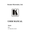
Figure 1 and Table 1 define the PL-8:
Figure 1: PL-8 Low Voltage Relay Controller
1 For example: model number AD2512C, part number 2535-000251
3
Your PL-8 Low Voltage Relay Controller
Table 1: PL-8 Low Voltage Relay Controller Features
#
Feature
1
REL Terminal Block (from 1 to 4) Connect to room items . The PINOUT is: NO: Normally Open;
C: Common Voltage; NC: Normally Closed
REL Terminal Block (from 5 to 8) Connect to room items1. The PINOUT is: NO: Normally Open;
C: Common Voltage
RS-232 Terminal Block
Connects to the RS-232 port on a PC
2
3
K-NET™ Terminal Block
PIN GND is for the Ground connection ; PIN B (-) and PIN A
Connector
(+) are for RS-485, and PIN +12V is for powering the unit
LINK LED
Illuminates when a link is established
ON LED
Illuminates when receiving power
Function
1
2
3
4
5
6
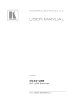
Figure 2 and Table 2 define the underside of the PL-8. On some units the
printing of the labels “RS-485 TERM” (instead of “PROGRAM”) and
“PROGRAM” (instead of “RS-485 TERM”) may be swapped around
erroneously. The correct labeling is defined in Figure 2 and Table 2.
Figure 2: PL-8 Underside
Table 2: Underside Features
#
Feature
Function
1
CONTROL DIP-switches 4
Set DIP 8 ON to use protocol 2000
Set DIP 8 0FF to use protocol 3000 over K-NET™
2
RS-485 TERM Switch
Switch for line termination of the unit
3
PROGRAM Switch
Switch to PROGRAM for firmware upgrade
1 Such as lighting, screen settings, blinds, and so on
2 K-NET is a proprietary Kramer protocol for interconnecting Kramer units
3 The ground connection is sometimes connected to the shield of the RS-485 cable (in most applications, it is not connected)
4 DIPs 1 to 7 are not used
4
KRAMER: SIMPLE CREATIVE TECHNOLOGY
Configuring the PL-8 Low Voltage Relay Controller
5
Configuring the PL-8 Low Voltage Relay Controller
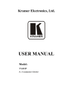
To connect the PL-8, as illustrated in the example in Figure 3, do the
following:
1. Connect the following items to the relays 1:
Window blinds to the REL 1 terminal block connector
A screen to the REL 3 terminal block connector
A projector lift to the REL 4 terminal block connector
The Kramer RB-8 8 Channel Power Controller 2 to the REL 8
terminal block connector
2. Connect a room controller via the K-NET™ terminal block connector, see
section 5.1.
Alternatively, you can connect a PC via the RS-232 port 3 (not shown in
Figure 3) 4.
Figure 3: Connecting the PL-8 Low Voltage Relay Controller
1 You can connect up to eight relays. You do not have to connect all of them
2 Refer to the Kramer RB-8 user manual at http://www.kramerelectronics.com
3 See section 5.2
4 When controlling the PL-8 via RS-232, connect the 12V terminal block connector to a 12V power supply
5
Configuring the PL-8 Low Voltage Relay Controller
5.1 The K-NET PINOUT
Figure 4 defines the K-NET™ PINOUT:
Room Controller
PINOUT
Black = GND
White = B
Green = A
Red = +12V
Figure 4: Wiring the K-NET Connector
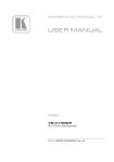
5.2 The RS-232 PINOUT
The RS-232 9-pin D-sub port PINOUT is defined in Figure 5 and Table 3:
RS-232 PINOUT
9
8
7
6
5
GND
4
3
Rx
2
1
Tx
Figure 5: RS-232 PINOUT Connection
Table 3: RS-232 PINOUT Connection
Connect this PIN on the
Terminal Block Connector:
Tx
Rx
GND
6
To this PIN on the
9-pin D-sub Connector
PIN 2
PIN 3
PIN 5
KRAMER: SIMPLE CREATIVE TECHNOLOGY
Firmware Upgrade
6
Firmware Upgrade
The PL-8 firmware is located in FLASH memory, which lets you upgrade to
the latest Kramer firmware version in minutes! The process involves:
• Downloading from the Internet (see section 6.1)
• Connecting the PC to the RS-232 port (see section 6.2)
• Upgrading Firmware (see section 6.3)
6.1
Downloading from the Internet
You can download the up-to-date file 1 from the Internet. To do so:
1. Go to our Web site at www.kramerelectronics.com and download the
file: “FLIP_PL8.zip” from the Technical Support section.
2. Extract the file: “FLIP_PL8.zip” to a folder (for example, C:\Program
Files\Kramer Flash).
3. Create a shortcut on your desktop to the file: “FLIP.EXE”.
6.2
Connecting the PC to the RS-232 Port
Before installing the latest Kramer firmware version on a PL-8 unit, do the
following:
1. Connect the RS-232 rear panel terminal block connector according to
section 5.2.
2. Disconnect the power.
3. Slide the underside switch to PROGRAM.
4. Connect the power.
6.3
Upgrading Firmware
Follow these steps to upgrade the firmware:
1. Double click the desktop icon: “Shortcut to FLIP.EXE”.
The Splash screen appears as follows:
1 The files indicated in this section are given as an example only. File names are liable to change from time to time
7
Firmware Upgrade
Figure 6: Splash Screen
2. After a few seconds, the Splash screen is replaced by the “Atmel – Flip”
window:
Figure 7: Atmel – Flip Window
3. Press the keyboard shortcut key F2 (or select the “Select” command from
the Device menu, or press the integrated circuit icon in the upper right
corner of the window).
The “Device Selection” window appears:
8
KRAMER: SIMPLE CREATIVE TECHNOLOGY
Firmware Upgrade
Figure 8: Device Selection Window
4. Click the button next to the name of the device and select from the list:
AT89C51RD2:
AT89C51RD2
T89C51RD2
Figure 9: Device Selection window
5. Click OK and select “Load Hex” from the File menu.
9
Firmware Upgrade
Figure 10: Loading the Hex
6. The Open File window opens. Select the correct HEX file that contains
the updated version of the firmware for PL-8 (for example
44M_V1p2.hex) and click Open.
7. Press the keyboard shortcut key F3 (or select the “Communication /
RS232” command from the Settings menu, or press the keys: Alt SCR).
The “RS232” window appears. Change the COM port according to the
configuration of your computer and select the 9600 baud rate:
Figure 11: RS-232 Window
10
KRAMER: SIMPLE CREATIVE TECHNOLOGY
Firmware Upgrade
8. Click Connect.
In the “Atmel – Flip” window, in the Operations Flow column, the Run
button is active, and the name of the chip appears as the name of the third
column: AT89C51RD2.
Verify that in the Buffer Information column, the “HEX File: PL8.hex”
appears.
Figure 12: Atmel – Flip Window (Connected)
9. Click Run.
After each stage of the operation is completed, the check-box for that
1
stage becomes colored green .
When the operation is completed, all 4 check-boxes will be colored green
2
and the status bar message: Memory Verify Pass appears :
1 See also the blue progress indicator on the status bar
2 If an error message: “Not Finished” shows, click Run again
11
Kramer Protocol15F
Figure 13: Atmel – Flip Window (Operation Completed)
10. Close the “Atmel – Flip” window.
11. Disconnect the power on the PL-8.
12. If required, disconnect the RS-232 terminal block connector on the PL-8
unit from the Null-modem adapter.
13. Slide the underside PROGRAM switch back to normal.
14. Connect the power to the PL-8.
7
Kramer Protocol 1
By default, the PL-8 is set to protocol 3000 (see section 7.1) but is also
compatible with Kramer’s Protocol 2000 (see section 7.2).
You can switch protocols by setting DIP-switch 8 OFF for protocol 3000 and
ON for protocol 2000.
7.1 PL-8 Commands in Protocol 2000
This RS-232/RS-485 communication protocol uses four bytes of information
as defined below. For RS-232, a null-modem connection between the
machine and controller is used. The default data rate is 9600 baud, with no
parity, 8 data bits and 1 stop bit.
1 You can download our user-friendly “Software for Calcul ating Hex Codes for Pr otocol 2000” from the technical support
section on our Web site at: http://www.kramerelectronics.com
12
KRAMER: SIMPLE CREATIVE TECHNOLOGY
Kramer Protocol
Table 4: Protocol Definitions
MSB
LSB
0
7
DESTINATION
INSTRUCTION
D
6
N5
5
N4
4
N3
3
N2
2
N1
1
N0
0
I5
5
I4
4
I3
3
I2
2
I1
1
I0
0
O3
3
O2
2
O1
1
O0
0
M2
2
M1
1
M0
0
1st byte
INPUT
1
7
I6
6
1
7
O6
6
O5
5
O4
4
1
7
OVR
6
X
5
M4
4
2nd byte
OUTPUT
3rd byte
MACHINE NUMBER
M3
3
4th byte
Bit 7 – Defined as 0.
1st BYTE:
D – “DESTINATION”:
0 - for sending information to the switchers (from the PC);
1 - for sending to the PC (from the switcher).
N5…N0 – “INSTRUCTION”
The function that is to be performed by the switcher(s) is defined by the INSTRUCTION (6 bits). Similarly, if a function is
performed via the machine’s keyboard, then these bits are set with the INSTRUCTION NO., which was performed. The
instruction codes are defined according to the table below (INSTRUCTION NO. is the value to be set for N5…N0).
2nd BYTE:
Bit 7 – Defined as 1.
I6…I0 – “INPUT”.
When switching (ie. instruction codes 1 and 2), the INPUT (7 bits) is set as the input number which is to be switched.
Similarly, if switching is done via the machine’s front-panel, then these bits are set with the INPUT NUMBER which was
switched. For other operations, these bits are defined according to the table.
3rd BYTE:
Bit 7 – Defined as 1.
O6…O0 – “OUTPUT”.
When switching (ie. instruction codes 1 and 2), the OUTPUT (7 bits) is set as the output number which is to be switched.
Similarly, if switching is done via the machine’s front-panel, then these bits are set with the OUTPUT NUMBER which was
switched. For other operations, these bits are defined according to the table.
4th BYTE:
Bit 7 – Defined as 1.
Bit 5 – Don’t care.
OVR – Machine number override.
M4…M0 – MACHINE NUMBER.
Used to address machines in a system via their machine numbers. When several machines are controlled from a single serial
port, they are usually configured together with each machine having an individual machine number. If the OVR bit is set, then
all machine numbers will accept (implement) the command, and the addressed machine will reply.
For a single machine controlled via the serial port, always set M4…M0 = 1, and make sure that the machine itself is
configured as MACHINE NUMBER = 1.
Table 5: Instruction Codes for Protocol 2000
Note: All values in the table are decimal, unless otherwise stated.
INSTRUCTION
DEFINITION FOR SPECIFIC INSTRUCTION
#
DESCRIPTION
INPUT
OUTPUT
0
44
RESET DEVICE
0
Set equal to control data
input which is to be switched
0=OFF
1=ON
0
SWITCH RELAY DATA
45
REQUEST STATUS OF RELAY
DATA OUTPUT
0
Set equal to control data
output which is to be
switched
Equal to output number
whose status is reqd
NOTE
1
2,27
3,4,27
13
Kramer Protocol
INSTRUCTION
DEFINITION FOR SPECIFIC INSTRUCTION
#
DESCRIPTION
INPUT
61
IDENTIFY MACHINE
NOTE
OUTPUT
video machine name
audio machine name
video software version
audio software version
RS422 controller name
RS422 controller version
remote control name
remote software version
Protocol 2000 revision
Control data machine name
Control data software version
Request first 4 digits
Request first suffix
Request second suffix
Request third suffix
Request first prefix
Request second prefix
Request third prefix
13
NOTES on the above table:
NOTE 1 – When the master switcher is reset, (e.g. when it is turned on), the reset code is sent to the PC. If this code is sent to
the switchers, it will reset according to the present power-down settings.
NOTES on the above table:
NOTE 1 - When the master switcher is reset, (e.g. when it is turned on), the reset code is sent to the PC. If this code is sent to
the switchers, it will reset according to the present power-down settings.
NOTE 2 - These are bi-directional definitions. That is, if the switcher receives the code, it will perform the instruction; and if
the instruction is performed (due to a keystroke operation on the front panel), then these codes are sent. For example, if the
HEX code
01
85
88
83
was sent from the PC, then the switcher (machine 3) will switch input 5 to output 8. If the user switched input 1 to output 7
via the front panel keypad, then the switcher will send HEX codes:
41
81
87
83
to the PC.
When the PC sends one of the commands in this group to the switcher, then, if the instruction is valid, the switcher replies by
sending to the PC the same four bytes that it was sent (except for the first byte, where the DESTINATION bit is set high).
NOTE 3 - SETUP # 0 is the present setting. SETUP # 1 and higher are the settings saved in the switcher's memory, (i.e. those
used for Store and Recall).
NOTE 4 - The reply to a "REQUEST" instruction is as follows: the same instruction and INPUT codes as were sent are
returned, and the OUTPUT is assigned the value of the requested parameter. The replies to instructions 10 and 11 are as per
the definitions in instructions 7 and 8 respectively. For example, if the present status of machine number 5 is breakaway
setting, then the reply to the HEX code
0B
80
80
85
would be HEX codes
4B
80
81
85
NOTE 13 - This is a request to identify the switcher/s in the system. If the OUTPUT is set as 0, and the INPUT is set as 1, 2,
5 or 7, the machine will send its name. The reply is the decimal value of the INPUT and OUTPUT. For example, for a 2216,
the reply to the request to send the audio machine name would be (HEX codes):
7D
96
90
81 (i.e. 128dec+ 22dec for 2nd byte, and 128dec+ 16dec for 3rd byte).
If the request for identification is sent with the INPUT set as 3 or 4, the appropriate machine will send its software version
number. Again, the reply would be the decimal value of the INPUT and OUTPUT - the INPUT representing the number in
front of the decimal point, and the OUTPUT representing the number after it. For example, for version 3.5, the reply to the
request to send the version number would be (HEX codes):
7D
83
85
81 (i.e. 128dec+ 3dec for 2nd byte, 128dec+ 5dec for 3rd byte).
If the OUTPUT is set as 1, then the ASCII coding of the lettering following the machine’s name is sent. For example, for the
VS-7588YC, the reply to the request to send the first suffix would be (HEX codes):
7D
D9
C3
81 (i.e. 128dec+ ASCII for “Y”; 128dec+ ASCII for “C”).
NOTE 27 –Bit 6 in the Output byte defines direction of the switched DATA (RS-232,RS- 485, RS-422). For bit 6=0 the
direction of the control DATA is from Input to Output; for bit 6=1 the direction of the reply DATA is oposite - from Output
to the Input.
14
Command
Example
Set relay On (Open)
0x02,0x81,0x80+Relay,0081
Set relay Off (Close)
0x02,0x80,0x80+Relay,0081
Read relay status
0x03,0x80,0x80+Relay,0081
KRAMER: SIMPLE CREATIVE TECHNOLOGY
Kramer Protocol
7.2 PL-8 Commands in Protocol 3000
This RS-232/RS-485 communication protocol 1 lets you control the machine
from any standard terminal software (for example, Windows®
HyperTerminal Application) and uses a data rate of 115200 baud, with no
parity, 8 data bits, and 1 stop bit. This section describes all commands sent to
the PL-8. For an explanation of the syntax and use of Protocol 3000, see
section 7.2.4.
7.2.1
Operating Commands
Following are the specific commands that the room controller (RC device)
sends to the PL-8 to operate the external devices.
Command
Syntax
Response
Relay control
RELAY RELAY_NUM, STATE
RELAY RELAY_NUM , STATE
RESULT
Command
Syntax
Response
Relay status
RELAY RELAY_NUM
RELAY RELAY_NUM
RESULT
Parameter Description:
RELAY_NUM = 1 to 8
STATE = Relay state:
‘0’ or ‘close’ to close the relay
‘1’ or ‘open’ to open the relay
Parameter Description:
RELAY_NUM = 1 to 8
7.2.2
Identification Commands
Command
Syntax
Response
Read device model
MODEL?
MODEL MACHINE_MODEL
Read device firmware
version
VERSION?
VERSION MAJOR .MINOR .BUILD .REVISION
7.2.3
Reset Command
Command
Syntax
Response
Reset device
RESET
RESET OK
7.2.4
K-NET management commands
Command
Syntax
Response
Change KNET number
Parameter Description:
KNET_ID
"1" or "Master"
"2" … (Slave)
KSET NEW_K_ID
KSET NEW_K_ID RESULT
1 Not available at the time of printing. Refer to our Web site at http://www.kramerelectronics.com for details
15
Kramer Protocol
Note:
* Command required Admin login.
* New ID will done only after device resetting
* Connecting 2 devices with same ID over one KNET network could cause unexpected behavior.
7.3 Protocol 3000 Syntax
Protocol 3000 is used to control the PL-8 via an RS-232 connection using a
PC, touch screen, other serial controller or RC type controller.
7.3.1
Host Message Format
Start
Address (optional)
Body
Delimiter
#
Destination_id@
Message
CR
7.3.1.1 Simple Command
Command string with only one command without addressing:
Start
Body
Delimiter
#
Command SP Parameter_1,Parameter_2,…
CR
7.3.1.2 Command String
Formal syntax with commands concatenation and addressing:
Start
Address
Body
Delimiter
#
Destination_id@
Command_1 Parameter1_1,Parameter1_2,…|
Command_2 Parameter2_1,Parameter2_2,…|
Command_3 Parameter3_1,Parameter3_2,…|…
CR
7.3.1.3 Device Message Format
Start
Address (optional)
Body
delimiter
~
Sender_id@
Message
CR LF
7.3.1.4 Device Long Response
Echoing command:
Start
Address (optional)
Body
Delimiter
~
Sender_id@
Command SP [Param1 ,Param2 …] result
CR LF
CR = Carriage return (ASCII 13 = 0x0D)
LF = Line feed (ASCII 10 = 0x0A)
SP = Space (ASCII 32 = 0x20)
16
KRAMER: SIMPLE CREATIVE TECHNOLOGY
Kramer Protocol
7.3.2
Command Terms
Command
A sequence of ASCII letters ('A'-'Z', 'a'-'z' and '-').
Command and parameters must be separated by at least one space.
Parameters
A sequence of alphameric ASCII characters ('0'-'9','A'-'Z','a'-'z' and some
special characters for specific commands). Parameters are separated by
commas.
Message string
Every command entered as part of a message string begins with a message
starting character and ends with a message closing character.
Note: A string can contain more than one command. Commands are
separated by a pipe ( '|' ) character.
Message starting character
'#' – For host command/query
'~' – For machine response
Device address (Optional, for K-NET)
K-NET Device ID followed by '@'
Query sign
'?' follows some commands to define a query request.
All outputs sign
'*' defines all outputs.
Message closing character
CR – For host messages; carriage return (ASCII 13)
CRLF – For machine messages; carriage return (ASCII 13) + line-feed (ASCII 10)
Command chain separator character
When a message string contains more then one command, a pipe ( '|' )
character separates each command.
Spaces between parameters or command terms are ignored.
7.3.3
Entering Commands
You can directly enter all commands using a terminal with ASCII
communications software, such as HyperTerminal, Hercules, etc. Connect the
terminal to the serial, Ethernet, or USB port on the Kramer device. To enter
CR , press the Enter key.
( LF is also sent but is ignored by command parser).
For commands sent from some non-Kramer controllers like Crestron, some
characters require special coding (such as, /X##). Refer to the controller
manual.
17
Technical Specifications
7.3.4
Command Forms
Some commands have short name syntax in addition to long name syntax to
allow faster typing. The response is always in long syntax.
7.3.5
Command Chaining
Multiple commands can be chained in the same string. Each command is
delimited by a pipe character ( '|' ). When chaining commands, enter the
message starting character and the message closing character only once, at
the beginning of the string and at the end.
Commands in the string do not execute until the closing character is entered.
A separate response is sent for every command in the chain.
7.3.6
Maximum String Length
64 characters
7.3.7
Backward Support
Protocol 2000 is transparently supported by Protocol 3000. You can switch
between protocols using a switch protocol command from either platform.
8
Technical Specifications
Table 6 includes the technical specifications:
1
Table 6: Technical Specifications of the PL-8 Low Voltage Relay Controller
INTERFACE:
RS-232 9-pin D-sub Connector
2 K-NET on terminal block connectors
OUTPUTS:
4 relays on terminal block connectors, NO: Normally Open; C: Common
Voltage; NC: Normally Closed (36V AC or DC, 2A, 60VAC maximum on
non-inductive load)
4 relays on terminal block connectors, NO: Normally Open; NC: Normally
Closed (36V AC or DC, 2A, 60VAC maximum on non-inductive load)
CONTROL:
LEDs: LINK and ON
POWER SOURCE: 12V DC 130mA
DIMENSIONS:
12.1cm x 7.18cm x 2.42cm (4.76" x 2.83" x 0.95"), W, D, H
WEIGHT:
0.3kg. (0.67lbs) approx.
ACCESSORIES:
Power supply, mounting bracket
1 Specifications are subject to change without notice
18
KRAMER: SIMPLE CREATIVE TECHNOLOGY
19
For the latest information on our products and a list of Kramer
distributors, visit our Web site: www.kramerelectronics.com,
where updates to this user manual may be found.
We welcome your questions, comments and feedback.
Safety Warning:
Disconnect the unit from the power supply before
opening/servicing.
Caution
Kramer Electronics, Ltd.
Web site: www.kramerelectronics.com
E-mail: [email protected]
P/N: 2900-000329 REV 1A