1
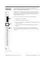
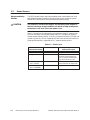
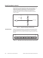
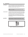
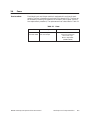
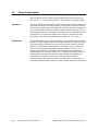
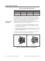
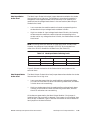
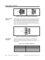
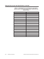
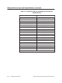
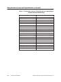
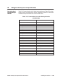
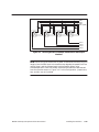
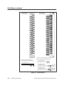
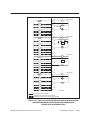
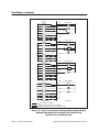
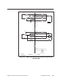
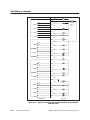
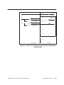
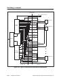
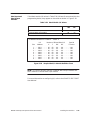
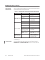
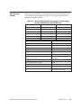
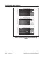
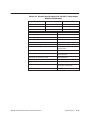
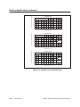
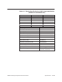
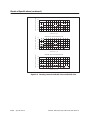
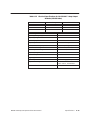
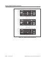
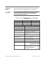
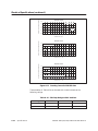
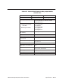
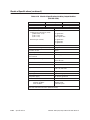
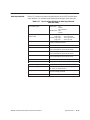
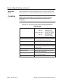
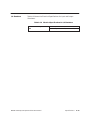
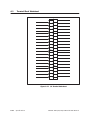
Wiring the Relay Output Modules (continued)
Table 3-14 Terminal Block Pin-out: 8-Point Relay Output Module
(PPX:505–4908)
User Connection
AR = Common 1
LED
–
User Connection
AC = Common 2
LED
–
A1 = N/O 1*
A1
A5 = N/O 2
A2
A2 = N/C 1**
A1
A6 = N/C 2
A2
A3 = Not Used
–
A7 = Not Used
–
A4 = Not Used
–
A8 = Not Used
–
BR = Common 3
–
BC = Common 4
–
B1 = N/O 3
B1
B5 = N/O 4
B2
B2 = N/C 3
B1
B6 = N/C 4
B2
B3 = Not Used
B4 = Not Used
–
B7 = Not Used
–
B8 = Not Used
–
–
CR = N/O 5
C1
CC = N/O 6
C2
C1 = N/C 5
C1
C5 = N/C 6
C2
C2 = Common 5
–
C6 = Common 6
–
C3 = Not Used
–
C7 = Not Used
–
C4 = Not Used
–
C8 = Not Used
–
DR = N/O 7
D1
DC = N/O 8
D2
D1 = N/C 7
D1
D5 = N/C 8
D2
D2 = Common 7
–
D6 = Common 8
–
D3 = Not Used
–
D7 = Not Used
–
D4 = User Coil Power (+)
–
D8 = User Coil Power (–)
–
Note: The LED follows the status of the N/O contact.
* N/O = Normally Open
** N/C = Normally Closed
3-18
Installing the Modules
SIMATIC 505 Input/Output Modules User Manual