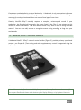
1
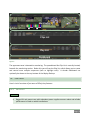
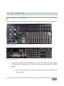
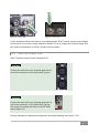
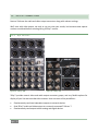
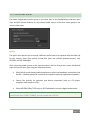
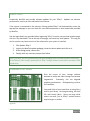
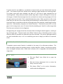
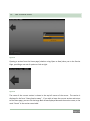
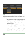
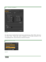
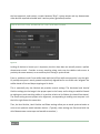
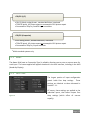
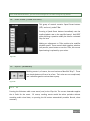
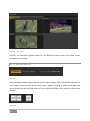
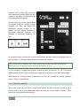
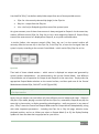
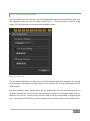
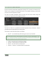
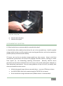
HDMI
A labeled HDMI connector on 3Play’s backplate tracks the active 3Play™ Output Mode (A or B).
Simply connect a suitable device to the HDMI connector on the backplane.
NETWORK OUTPUT
Figure 24
3Play’s Output A and Output B are available as Switcher sources to a network connected
TriCaster™. There is nothing to configure on 3Play™. Provided the two units are on the same
network (not different subnets), they will appear in the source selector menu for TriCaster’s Net
1 and Net 2 inputs as “3Play(A)” and “3Play(B),” where “3Play” is the network name for the
system. Conveniently, the output includes embedded audio, freeing up multiple TriCaster a/v
inputs for other purposes.
MULTIVIEW
3Play’s Multiview output is variously supplied by a DVI connector (3Play™ 820), or HDMI
connector (3Play™ 425) located near the interface DVI connector. Again, connect a suitable
external monitor or device. The new device should be recognized and enabled by the system
automatically. This output offers a variety of optional monitoring layouts that can be selected at
any time in the Replay Desktop.
Note: For best results, it is important to configure Multiview Output to the native resolution of
the external display (monitor or projector) connected.
3.5.5 TALLY LIGHTS
You may notice that 3Play’s backplate connections include a DB-15 port labeled Tally. This is
intended for future expansion. At the present time, the connector is not active.
Page | 25