1
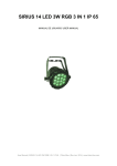
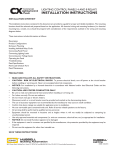
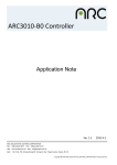
THE FLASH PRODUCER USER MANUAL HungaroFLASH LED STROBEs 1.5k Luminaires 1 HungaroFLASH LED STROBEs USER MANUAL V1 version December 2014 IMPORTANT INFORMATION The material in this manual is for information purposes only and is subject to change without notice. HungaroFLASH assumes no responsibility for any errors or omissions which may appear in this manual. For comments and suggestions regarding corrections and/or updates to this manual, please contact your nearest HungaroFLASH distributor. Warnings and Notices This product is for Professional use only! It’s not for household use. READ AND FOLLOW ALL SAFETY INSTRUCTIONS! Do not use outdoors. Do not open: there are no user serviceable part inside Use only a source of AC power that complies with local building and electrical codes and has both OVERLOAD and EARTH LEAKAGE protection ALWAYS ground the LED STROBE electrically Additional Resources for DMX512 For more information on installing DMX512 control systems, the following publication is available for purchase from the United States Institute for Theatre Technology (USITT), "Recommended Practice for DMX512: A Guide for Users and Installers, 2nd edition" (ISBN: 9780955703522). USITT Contact Information: USITT 315 South Crouse Avenue, Suite 200 Syracuse, NY 13210-1844 Phone: 1.800.938.7488 or 1.315.463.6463 www.usitt.org Additional Resources for Remote Device Management over DMX512 Networks - RDM For more information on installing RDM-DMX512 control systems, the following publication is available for purchase from the ANSI E1.20 - 2010 Entertainment Technology RDM Remote Device Management over DMX512 Networks. Copyright 2011 PLASA NA. All rights reserved. CP/2009-1017r2 Approved as an American National Standard by the ANSI Board of Standards Review on 4 January 2011 Published By: PLASA North America - 630 Ninth Avenue, Suite 609 - New York, NY 10036 - USA Phone: 1-212-244-1505 / Fax: 1-212-244-1502 Email: [email protected] For additional copies of this document contact: The ESTA Foundation - 630 Ninth Avenue, Suite 609 - New York, NY 10036 - USA Phone: 1-212-244-1505 / Fax: 1-212-244-1502 http://www.estafoundation.org HungaroFLASH Limited Two-Year Warranty HungaroFLASH offers a two-year limited warranty of its luminaires against defects in materials or workmanship from the date of delivery. A copy of HungaroFLASH two-year limited warranty containing specific terms and conditions can be obtained by contacting your local HungaroFLASH distributor. For more information please visit http://www.hungaroflash.com/dealer-list 2 HungaroFLASH LED STROBEs USER MANUAL V1 version December 2014 TABLE of CONTENTS IMPORTANT INFORMATION------------------------------------------------------------------------------ 2 WARNINGS AND NOTICES --------------------------------------------------------------------------------------------- 2 ADDITIONAL RESOURCES FOR DMX512 ------------------------------------------------------------------------------- 2 ADDITIONAL RESOURCES FOR REMOTE DEVICE MANAGEMENT OVER DMX512 NETWORKS - RDM ---------------------------- 2 HUNGAROFLASH LIMITED TWO-YEAR WARRANTY ----------------------------------------------------------------------- 2 TABLE OF CONTENTS ------------------------------------------------------------------------------------- 3 PREFACE --------------------------------------------------------------------------------------------------- 4 ABOUT THIS MANUAL ------------------------------------------------------------------------------------------------- 4 INCLUDED ITEMS -------------------------------------------------------------------------------------------------- 4 HUNGAROFLASH LED STROBE LUMINAIRE ACCESSORIES ---------------------------------------------------------------- 4 LED STROBE OVERVIEW ----------------------------------------------------------------------------------- 5 MAJOR COMPONENTS AND TERMINOLOGY --------------------------------------------------------------------------- 5 ADJUSTABLE MANUAL YOKE AND/OR CONTROL BOX ------------------------------------------------------------- 6 OLED DISPLAY / MENU SYSTEM ----------------------------------------------------------------------------------- 6 INSTALLATION AND SET UP ------------------------------------------------------------------------------ 7 POWER REQUIREMENTS------------------------------------------------------------------------------------------- 7 AC POWER OPERATION ---------------------------------------------------------------------------------------------- 7 FOR WIRING OF AC INPUT CONNECTOR, REFER TO “CONNECTING TO HUNGAROFLASH LED STROBES TO AC POWER” ON PAGE 8.----------------------------------------------------------------------------------------------------------------- 7 CONNECTING POWER ------------------------------------------------------------------------------------------------- 8 CONNECTING TO HUNGAROFLASH LED STROBE S TO AC POWER --------------------------------------------------------- 8 CONNECTING TO THE DMX512 / RDM NETWORK -------------------------------------------------------------------- 9 MOUNTING LUMINAIRE----------------------------------------------------------------------------------------------- 10 OPERATION AND PROGRAMMING---------------------------------------------------------------------- 11 OLED DISPLAY AND MENU SYSTEMS ------------------------------------------------------------------------------ 11 START SCREEN ---------------------------------------------------------------------------------------------------------- 11 OLED DISPLAY AND MENU SYSTEM NAVIGATION ------------------------------------------------------------------- 11 CONTROL MENU - MENU MAP----------------------------------------------------------------------------------- 12 DMX ADDRESS ----------------------------------------------------------------------------------------------------- 13 DMX CONTROL ------------------------------------------------------------------------------------------- 14 SINGLE CHANNEL MODE AS IT ON DISPLAY: AC-1 ------------------------------------------------------------------- 14 THREE CHANNEL MODE AS IT ON DISPLAY: AC-3 ------------------------------------------------------------------- 14 FOUR CHANNEL MODE AS IT ON DISPLAY: AC-4 -------------------------------------------------------------------- 15 SIX CHANNEL MODE AS IT ON DISPLAY: AC-6 ---------------------------------------------------------------------- 15 SEVEN CHANNEL MODE AS IT ON DISPLAY: AC-7 ------------------------------------------------------------------- 16 SEVEN CHANNEL LEGACY MODE AS IT ON DISPLAY: AC-7 LEGACY ---------------------------------------------------- 17 THREE CHANNEL MODE AS IT ON DISPLAY: 3 PIXEL---------------------------------------------------------------- 17 EIGHT CHANNEL MODE AS IT ON DISPLAY: Q7-8 ------------------------------------------------------------------- 18 TWO CHANNEL MODE AS IT ON DISPLAY: DMX NORMAL ------------------------------------------------------------- 19 TWO CHANNEL MODE AS IT ON DISPLAY: HUNGAROFLASH---------------------------------------------------------- 19 STROBE RATE DMX TIMING DETAIL --------------------------------------------------------------------------------20 STROBE DURATION DMX TIMING DETAIL --------------------------------------------------------------------------- 21 STROBE RATE DMX TIMING DETAIL HF -----------------------------------------------------------------------------22 STROBE DURATION DMX TIMING DETAIL HF -----------------------------------------------------------------------23 HUNGAROFLASH LED STROBE LUMINAIRE RDM PARAMETER IDS ---------------------------------------------------24 CLEANING AND CARE ----------------------------------------------------------------------------------- 26 SPECIAL CLEANING AND CARE INSTRUCTIONS ---------------------------------------------------------------------------26 FRONT GLASS CLEANING --------------------------------------------------------------------------------------------26 SERVICE AND MAINTENANCE ------------------------------------------------------------------------------------------26 TECHNICAL SPECIFICATIONS --------------------------------------------------------------------------- 27 HUNGAROFLASH LED STROBE LUMINAIRE OPERATIONAL SPECIFICATIONS --------------------------------------------- 27 HUNGAROFLASH LED STROBE LUMINAIRE DIMENSIONS ------------------------------------------------------------- 27 3 HungaroFLASH LED STROBEs USER MANUAL V1 version December 2014 PREFACE About this Manual The document provides installation and operation instructions for the following products: 1. HungaroFLASH 1.5k SOL - LED STROBE Luminaire 2. HungaroFLASH 1.5k RGB - LED STROBE Luminaire 3. HungaroFLASH 1.5k UV - LED STROBE Luminaire Please read all instructions before installing or using this product. Retain this manual for future reference. Additional product information and descriptions may be found on the product specification sheet. INCLUDED ITEMS Each LED STROBEs includes the following items: 1. LED STROBE Luminaire 2. MIRROR system for 600 beam angle – 3 pcs Without mirrors the beam angle is 1200 3. USER MANUAL 4. AC Power Cable POWERCON 2m cable SCHUKO plug 16A 5. Mounting BRACKETS – OMEGA type – 2 pcs HungaroFLASH LED STROBE Luminaire Accessories Part Number HFLEDPC2 HFLEDMIR3 HFLEDMBO2 Description Power Cable – 2 meter including POWERCON – to Main MIRROR system for 600 beam angle – 3 pcs Mounting BRACKETS – OMEGA type – 2 pcs Optional Accessories HFLEDPC1 Power Cable – 1 meter including POWERCON Female and connectors for cable – for the NEXT device Power connection. HFLEDDMx1 DMX Cable – including Male and Female 5-PIN XLR plug– 1 meter HFLEDHAN Adjustable Clamping Lever (steel) - 2 pcs 4 HungaroFLASH LED STROBEs USER MANUAL V1 version December 2014 LED STROBE overview Major COMPONENTs and Terminology MANUAL YOKE Release and LOCK MIRROT NET (600 beam angle) MANUAL YOKE Without MIRRORs 1200 beam angle High INTENSITY LED ARRAY (1452) FRONT GLASS (TEMPERED) CONTROL BOX Release and LOCK Mounting Brackets OMEGA TYPE receiver points CONTROL BOX AC Input AC Output DMX Input OLED DISPLAY / Menu System DMX Output 5 HungaroFLASH LED STROBEs USER MANUAL V1 version December 2014 ADJUSTABLE MANUAL YOKE and/or CONTROL BOX The following figures illustrates the end positions of the MANUAL YOKE and end positions of the CONTROL BOX Rotations. Between this two end positions the MANUAL YOKE can be locked to any position from 00 to 1500. CONTROL BOX can be locked to any position from 00 to 1800. MANUAL YOKE CONTROL BOX NOTE: For more Installation and Mounting instruction, refer to the “Mounting Luminaire” on page 10. OLED DISPLAY / MENU SYSTEM This is the start SCREEN set by HungaroFLASH factory. Each HungaroFLASH LED STROBE after first FACTORY release is look like this: DISPLAY and MENU COMPONENTS Multifunction BUTTONs NOTE: Menu orientation ROTATES AUTOMATICALLY. It has a sensor to read out mounting directions. For MENU OPERATION and PROGRAMMING details, refer to “DISPLAY and MENU SYSTEM” on page 11. 6 HungaroFLASH LED STROBEs USER MANUAL V1 version December 2014 INSTALLATION and SET UP POWER REQUIREMENTs The following LUMINAIREs operates AC input voltages from 100 to 255 VAC: 1. HungaroFLASH 1.5k SOL - LED STROBE Luminaire 2. HungaroFLASH 1.5k RGB - LED STROBE Luminaire 3. HungaroFLASH 1.5k UV - LED STROBE Luminaire AC POWER OPERATION When connected to AC source, the units operates on 100 – 255 volts AC auto-ranging. The LED STROBEs contains an AUTO-RANGING power supply. Each luminaire can draw up to 460 Watts peak power. When connected to 50Hz or 60Hz power lines, the unit AUTOMATICALLY selecting between the two operation modes to allow same functionality for both 50Hz and 60Hz. Regarding this this LED STROBES can be operates next to a HungaroFLASH XENON STROBEs, which has a same feature TABLE 1 LED STROBE CURRENT VERSUS VOLTAGE When using Daisy-chained connection method between LED strobes, only connect HungaroFLASH LED Strobes luminaires to AC Output connection of HungaroFLASH LED Strobes. DO NOT CONNECT OTHER TYPE OF LUMINAIRES OR DEVICES! Do NOT connect HungaroFLASH LED Strobes to any DIMMED circuits! Do not overload circuits! The MAXIMUM amount of LED Strobes luminaires which may be daisy-chained on ONE power feed are listed in TABLE 1, next, DO NOT EXCEED! Warning! This unit does not contain ON/OFF switch at all. Please unplug the device completely to remove the POWER from unit when not in use. Attention: The PowerCon® is a connector without 20A breaking capacity!! The PowerCon® should not be connected or disconnected under load or live! Maximum amount of units that may be daisy-chained is 3 units on 90VAC (20Amps) or 3 units on 90VAC (16Amps) or 11 units on 250VAC (20Amps) or 8 units on 250VAC (16Amps). Refer to TABLE 1 for detailed information at various Voltages. Voltage (AC) 250 240 230 220 210 200 190 180 170 160 150 140 130 120 110 100 90 TOTAL current (A) Maximum number of units1 Maximum number of units2 1,78 11 10 10 9 9 8 8 7 7 7 6 6 5 5 4 4 3 8 8 8 7 7 7 6 6 5 5 5 4 4 4 3 3 3 1,87 1,96 2,07 2,18 2,26 2,4 2,51 2,74 2,81 3,03 3,26 3,51 3,85 4,22 4,66 5,29 For wiring of AC input connector, refer to “Connecting to HungaroFLASH LED STROBEs to AC Power” on Page 8. 7 Document Number: HungaroFLASH LED STROBEs USER MANUAL version December 2014 Connecting Power Units can be powered in two ways: 1. 2. Direct connected to AC power line using AC input cable. For wiring of AC input connector, refer to CONNECT “HungaroFLASH LED STROBEs to AC Power” on this Page 8 below here. Connection from the AC OUTPUT of another HungaroFLASH LED STROBEs. When connect this way, it’s very important not to connect any other type of equipment Device. WARNING! Only connect other HungaroFLASH LED STROBEs to the AC OUTPUT (THRU) connector of a HungaroFLASH LED STROBEs. Connecting to HungaroFLASH LED STROBEs to AC Power HungaroFLASH LED STROBEs are supplied with an AC input cable -2meter- with input connector installed and 16A SCHUKO connector installed on. In case when example cable length is not enough and need to change cable to custom size by user, the following TABLE 2 describes how to connect power to your HungaroFLASH LED STROBEs. TABLE 2 HUNGAROFLASH LED STROBES LUMINAIRE AC I NPUT CONNECTIONS WIRE color Brown Blue Yellow/Green PURPOSE Main / Line / 90-240VAC Neutral Ground (Earth) Back of the HungaroFLASH LED STROBEs AC Output Connector (on unit) AC Input Connector (on unit) Neutral Neutral Main / Line Ground / Earth 8 Ground / Earth HungaroFLASH LED STROBEs USER MANUAL V1 version December 2014 CAUTION: In the event the AC INPUT cable of this Luminaire is DAMAGED, it must be replaced, by the user, with an approved cable through a HungaroFLASH distributor or Service . CONNECTING to the DMX512 / RDM Network Basic DMX512installation consists of connecting multiple HungaroFLASH LED STROBEs Luminaires together (up to 32 luminaires) in “daisy-chain” fashion. A DMX Cable runs from the control console (or DMX control source) to the DMX IN connector on the first HungaroFLASH LED STROBE luminaire. Another cable runs from the DMX OUT connector on the first unit to the next Luminaire DMX IN connector (or other DMX/RDM device to be controlled). DMX512/RDM From Console or Control DEVICE DMX Input DMX Output DMX512/RDM OUT from 1st to 2nd luminaire IN DMX Input DMX Output DMX512/RDM OUT from 2nd to 3rd luminaire IN DMX Input DMX Output DMX512/RDM OUT from 3rd to 4th luminaire IN DMX Input DMX Output Cabling must have a male 5-pin XLR connector on one end and a female 5-pin XLR connector on the other end. Note: For more information on DMX512 networking and systems or RDM networking and systems, refer to “Additional Resources for DMX512” or “Additional Resources for Remote Device Management over DMX512 Networks – RDM” on page 2. For HungaroFLASH LED STROBE luminaire DMX Mapping, refer to “DMX CONTROL” on page 14. TABLE 3 HUNGAROFLASH LED STROBES – DMX512/RDM CONNECTIONS DMX512 Signal wires Common (Drain) DMX512 DMX512 + XLR 5-PIN 1 2 3 4 5 Cabling must have a male 5pinXLR connector on one end and a female 5-pin XLR connector on the other end not used not used 9 HungaroFLASH LED STROBEs USER MANUAL V1 version December 2014 Mounting Luminaire HungaroFLASH LED STROBEs are provided with the ability to hang via truss hooks, clamps using the Mounting BRACKETs OMEGA type – 2pcs (or just 1 pc) QUICK connected to the MANUAL YOKE. Hooks, clamps sold separately. Simply attach hook, clamp, etc. to the HungaroFLASH LED STROBE Luminaire’s Mounting BRACKETs OMEGA type in the provided M10 holes. It’s recommended (and may be required by local and national safety codes) to use and install a safety cable (sold separately). When hanging the fixture, be sure to leave enough space around the luminaire to allow proper airflow for natural cooling purposes and positioning. Adjust the fixture to the desired angle. After installation release the two Adjustable Clamping Lever (steel) to the desired angel. Then tighten well by hand and index the arm of Adjustable Clamping Lever (steel) as it’s desired. Control Box is also adjustable after releasing its Adjustable Clamping Lever (steel) then tight well as its desired direction for DMX and Power Cables. Mounting with 1 MOUNTING BRACKET: Mounting with 2 MOUNTING BRACKETs: Adjustable clamping lever SAFETY GLOVES: Is sold separately and recommended for all hanging installation and may be required by national and local codes. SAFETY CABLE: Is sold separately and recommended for all hanging installation and may be required by national and local codes. Use safety cable for MANUAL YOKE like this picture. HungaroFLASH LED STORBEs luminaires may be mounted in any position. 10 HungaroFLASH LED STROBEs USER MANUAL V1 version December 2014 OPERATION and PROGRAMMING OLED DISPLAY and MENU SYSTEMs The HungaroFLASH LED STROBEs Luminaire’s DISPLAY and MENU SYSTEM provides local control for accessing the following fixture’s settings: Fixture settings Strobe DMX modes/ Settings compatibility with other systems Current fixture Temperature Current Fixture Status Information Setting the DMX512 Addresses Upon power up, the DISPLAY will show the following Starting screen: Start Screen L MULTIFUNCTIONAL Buttons Programmed DMX MODE is AC-4 (4 channel mode see “DMX MODE selection”, refer to page 15) Programmed DMX address will appear after power up (after first factory release this value is 001). If DMX presents, this DMX signal indicator is light. If you don’t see this DMX, this indicates the DMX connection has a problem - HungaroFLASH LED STROBE model type/name mark. This mark can be - W --- HungaroFLASH 1.5k SOL - LED STROBE Luminaire - RGB ---HungaroFLASH 1.5k RGB - LED STROBE Luminaire - UV --- HungaroFLASH 1.5k UV - LED STROBE Luminaire 3 MULTIFUNCTIONAL Buttons out of 4 has here functions on the START screen: - T --- Current Temperature on LEDs i --- Channel INFO. Actual channel numbers and purposes - ≡ --- MENU selector Each functions of MULTIFUNCTIONAL Buttons can be remote by for Remote Device Management over DMX512 Networks – RDM. For Remote Device Management over DMX512 Networks DISPLAY and MENU SYSTEMs, refer to the console User manual that is actually using to Remote the Luminaires. - OLED DISPLAY and MENU SYSTEM navigation The DISPLAY and MANU systems consist of several categories. Use the ≡ MENU selector on display to access and make changes. To navigate and access MENU settings/selections: Step 1. Make sure unit is powered and turned ON Step 2. Press the desired MULTIIFUNCTIONAL Button to access MENU categories Step 3. Use Up/Down MULTIFUNCTIONAL Buttons to navigate through the various options and settings. Use X MULTIFUNCTIONAL Button to navigate one step BACK or MULTIFUNCTIONAL Button to accept selection √ Step 4. Make changes as desired. Use X MULTIFUNCTIONAL Button to navigate one step BACK or √ MULTIFUNCTIONAL Button to accept selection 11 HungaroFLASH LED STROBEs USER MANUAL Control MENU - MENU MAP After START SCREEN you have 3 option to navigate in the MENU System: 12 V1 version December 2014 HungaroFLASH LED STROBEs USER MANUAL V1 version December 2014 DMX Address You can display and edit the current DMX start address for the fixture by pressing the MULTIFUNCTIONAL Button according to MENU symbol. The current DMX start address will be display in LARGE DIGITS and after this start address the next line displays the following fixture START Address according to the actual DMX channel set up calculation. To edit the DMX start address: 1. Press MENU button to entering to the MENU system. 2. Press √ 3. Press / 4. Press √ Check Mark button to save the new DMX start address. In the same moment you see the next fixture Start address. Check Mark button to begin the DMX start address editing. Up/Down arrows to change the DMX start value as desired. 13 HungaroFLASH LED STROBEs USER MANUAL V1 version December 2014 DMX Control This section contains information for operating the luminaire using one of the DMX control MODEs as set by the luminaire’s MENU SYSTEM: Single Channel Mode as it on DISPLAY: AC-1 Three Channel Mode as it on DISPLAY: AC-3 Four Channel Mode as it on DISPLAY: AC-4 Six Channel Mode as it on DISPLAY: AC-6 Seven Channel Mode as it on DISPLAY: AC-7 Seven Channel Mode as it on DISPLAY: AC-7 Legacy Three Channel Mode as it on DISPLAY: 3 PIXEL Eight Channel Mode as it on DISPLAY: Q7-8 Two Channel Mode as it on DISPLAY: DMX normal Two Channel Mode as it on DISPLAY: HungaroFLASH NOTE: These tables assume a DMX Start address of 1. When a different starting address is used, this address becomes channel 1 function and other function follow is sequence. Single Channel Mode as it on DISPLAY: AC-1 Table 4 provides DMX Channel mapping of the DMX512 control values when the HungaroFLASH LED STROBE Luminaire is in AC-1 (Single Channel DMX512 mode) (as set by the luminaire’s menu system). AC-1 TABLE 4: AC-1 CHANNEL MAPPING (SINGLE CHANNEL MODE) DMX Channel DMX value/ range DMX 0-5 1 6-249 250-255 Percent / Range% 0-1 2-97 98-100 Description Blackout FLASH RATE slow-fast CONTINUOUS – Blinder effect ”Strobe Rate DMX Timing Detail” on page 20 Three Channel Mode as it on DISPLAY: AC-3 Table 5 provides DMX Channel mapping of the DMX512 control values when the HungaroFLASH LED STROBE Luminaire is in AC-3 (Three Channel DMX512 mode) (as set by the luminaire’s menu system). TABLE 5: AC-3 CHANNEL MAPPING (THREE CHANNEL MODE) AC-3 DMX Channel DMX value/ range DMX Percent / Range% 1 0-5 6-255 0-1 2-100 2 0-255 0-100 Description FLASH intensity Blackout Min to MAX Intensity FLASH duration 0-640ms @ 50 Hz AC 0-533ms @ 60 Hz AC "Strobe Duration DMX Timing Detail" on page 21 3 0-5 6-255 0-1 2-100 FLASH rate NO FLASH! 0,5-25Hz @ 50Hz AC 0,6-30Hz @ 60Hz AC "Strobe Rate DMX Timing Detail" on page 20 14 HungaroFLASH LED STROBEs USER MANUAL V1 version December 2014 Four Channel Mode as it on DISPLAY: AC-4 Table 6 - 7 provides DMX Channel mapping of the DMX512 control values when the HungaroFLASH LED STROBE Luminaire is in AC-4 (Four Channel DMX512 mode) and AC-6 (Six channel DMX512 mode) (as set by the luminaire’s menu system). TABLE 6: AC-4 CHANNEL MAPPING (FOUR CHANNEL MODE) DMX Channel DMX value/ range DMX Percent / Range% 1 0-5 6-255 0-1 2-100 2 0-255 0-100 Description FLASH intensity Blackout Min to MAX Intensity FLASH duration 0-640ms @ 50 Hz AC 0-533ms @ 60 Hz AC 3 0-5 6-255 0-1 2-100 FLASH rate NO FLASH! 0,5-25Hz @ 50Hz AC 0,6-30Hz @ 60Hz AC AC-4 "Strobe Duration DMX Timing Detail" on page 21 "Strobe Rate DMX Timing Detail" on page 20 4 0-5 6-42 43-85 86-128 129-171 172-214 215-255 0-1 2-16 17-33 34-50 51-67 68-83 84-100 Special effect No effect! Ramp up Ramp down Ramp up than down Random Lightning Spikes Six Channel Mode as it on DISPLAY: AC-6 TABLE 7: AC-6 CHANNEL MAPPING (SIX CHANNEL MODE) Percent / Range% 1 0-5 6-255 0-1 2-100 2 0-5 6-255 0-1 2-100 3 0-5 6-255 0-1 2-100 4 0-5 6-255 0-1 2-100 5 0-255 0-100 Description MASTER FLASH intensity Blackout Min to MAX Intensity RED/ Segment 1 intensity Intensity of RED (RGB) Or SEGMENT 1 (SOL-UV) GREEN/ Segment 2 intensity Intensity of GREEN (RGB) Or SEGMENT 2 (SOL- UV) BLUE/ Segment 3 intensity Intensity of BLUE (RGB) Or SEGMENT 3 (SOL- UV) FLASH duration 0-640ms @ 50 Hz AC 0-533ms @ 60 Hz AC AC-6 DMX Channel DMX value/ range DMX "Strobe Duration DMX Timing Detail" on page 21 6 0-5 6-255 0-1 2-100 FLASH rate NO FLASH! 0,5-25Hz @ 50Hz AC 0,6-30Hz @ 60Hz AC "Strobe Rate DMX Timing Detail" on page 20 15 HungaroFLASH LED STROBEs USER MANUAL V1 version December 2014 Seven Channel Mode as it on DISPLAY: AC-7 Table 8 provides DMX Channel mapping of the DMX512 control values when the HungaroFLASH LED STROBE Luminaire is in AC-7 (Seven Channel DMX512 mode) (as set by the luminaire’s menu system). TABLE 8: AC-7 CHANNEL MAPPING (SEVEN CHANNEL MODE) DMX Channel DMX value/ range DMX Percent / Range% 1 0-5 6-255 0-1 2-100 2 0-255 0-100 Description MASTER FLASH intensity Blackout Min to MAX Intensity FLASH duration 0-640ms @ 50 Hz AC 0-533ms @ 60 Hz AC "Strobe Duration DMX Timing Detail" on page 21 3 0-5 6-255 0-1 2-100 FLASH rate NO FLASH! 0,5-25Hz @ 50Hz AC 0,6-30Hz @ 60Hz AC AC-7 "Strobe Rate DMX Timing Detail" on page 20 16 0-5 6-42 43-85 86-128 129-171 172-214 215-255 0-1 2-16 17-33 34-50 51-67 68-83 84-100 5 0-255 0-1 2-100 6 0-255 0-1 2-100 7 0-255 0-1 2-100 4 Special effect No effect! Ramp up Ramp down Ramp up than down Random Lightning Spikes RED/ Segment 1 intensity Intensity of RED (RGB) Or SEGMENT 1 (SOL- UV) GREEN/ Segment 2 intensity Intensity of GREEN (RGB) Or SEGMENT 2 (SOL- UV) BLUE/ Segment 3 intensity Intensity of BLUE (RGB) Or SEGMENT 3 (SOL- UV) HungaroFLASH LED STROBEs USER MANUAL V1 version December 2014 Seven Channel LEGACY Mode as it on DISPLAY: AC-7 Legacy Table 9 provides DMX Channel mapping of the DMX512 control values when the HungaroFLASH LED STROBE Luminaire is in AC-7 Legacy (Seven Channel DMX512 mode) (as set by the luminaire’s menu system). TABLE 9: AC-7 CHANNEL MAPPING (SEVEN CHANNEL MODE) DMX value/ range DMX Percent / Range% 1 0-5 6-255 0-1 2-100 2 0-5 6-255 0-1 2-100 3 0-5 6-255 0-1 2-100 4 0-5 6-255 0-1 2-100 5 0-255 0-100 Description MASTER FLASH intensity Blackout Min to MAX Intensity RED/ Segment 1 intensity Intensity of RED (RGB) Or SEGMENT 1 (SOL-UV) GREEN/ Segment 2 intensity Intensity of GREEN (RGB) Or SEGMENT 2 (SOL- UV) BLUE/ Segment 3 intensity Intensity of BLUE (RGB) Or SEGMENT 3 (SOL- UV) FLASH duration 0-640ms @ 50 Hz AC 0-533ms @ 60 Hz AC "Strobe Duration DMX Timing Detail" on page 21 6 0-5 6-255 0-1 2-100 FLASH rate NO FLASH! 0,5-25Hz @ 50Hz AC 0,6-30Hz @ 60Hz AC AC-7 Legacy DMX Channel "Strobe Rate DMX Timing Detail" on page 20 7 0-5 6-42 43-85 86-128 129-171 172-214 215-255 0-1 2-16 17-33 34-50 51-67 68-83 84-100 Special effect No effect! Ramp up Ramp down Ramp up than down Random Lightning Spikes Three Channel Mode as it on DISPLAY: 3 PIXEL TABLE 10: 3 PIXEL CHANNEL MAPPING (THREE CHANNEL MODE) DMX value/ range DMX Percent / Range% 1 0-5 6-255 0-1 2-100 2 0-5 6-255 0-1 2-100 3 0-5 6-255 0-1 2-100 Description RED/ Segment 1 intensity Intensity of RED (RGB) Or SEGMENT 1 (SOL-UV) GREEN/ Segment 2 intensity Intensity of GREEN (RGB) Or SEGMENT 2 (SOL- UV) BLUE/ Segment 3 intensity Intensity of BLUE (RGB) Or SEGMENT 3 (SOL- UV) 3 PIXEL DMX Channel 17 HungaroFLASH LED STROBEs USER MANUAL V1 version December 2014 Eight Channel Mode as it on DISPLAY: Q7-8 Table 11 provides DMX Channel mapping of the DMX512 control values when the HungaroFLASH LED STROBE Luminaire is in Q7-8 (Eight Channel DMX512 mode) (as set by the luminaire’s menu system). This MODE requires two strobes (Strobe 1 is RGB and Strobe 2 is a WHITE) to get it work. See the following figure for further connection information: RGB Strobe Strobe RGB Strobe Strobe TABLE 11: Q7-8 CHANNEL MAPPING (EIGHT CHANNEL MODE) DMX Channel DMX value/ range DMX Percent / Range% 1 0-5 6-255 0-1 2-100 2 0-255 0-100 Description FLASH intensity Blackout Min to MAX Intensity FLASH duration 0-640ms @ 50 Hz AC 0-533ms @ 60 Hz AC "Strobe Duration DMX Timing Detail" on page 21 3 0-5 6-255 0-1 2-100 FLASH rate NO FLASH! 0,5-25Hz @ 50Hz AC 0,6-30Hz @ 60Hz AC Q7-8 "Strobe Rate DMX Timing Detail" on page 20 18 0-5 6-42 43-85 86-128 129-171 172-214 215-255 0-1 2-16 17-33 34-50 51-67 68-83 84-100 5 0-255 0-1 2-100 6 0-255 0-1 2-100 7 0-255 0-1 2-100 Special effect No effect! Ramp up Ramp down Ramp up than down Random Lightning Spikes RED Intensity of RED (RGB) On RGB Strobe GREEN Intensity of GREEN (RGB) On RGB Strobe BLUE Intensity of BLUE (RGB) On RGB Strobe 8 0-255 0-1 2-100 Intensity of On Strobe 4 HungaroFLASH LED STROBEs USER MANUAL V1 version December 2014 Two Channel Mode as it on DISPLAY: DMX normal Table 12 provides DMX Channel mapping of the DMX512 control values when the HungaroFLASH LED STROBE Luminaire is in DMX normal mode (Two Channel DMX512 mode) (as set by the luminaire’s menu system). This MODE allow you to use HungaroFLASH LED STOBEs strobes with other HungaroFLASH XENON type strobes and perform synchronal flashing show if desired. TABLE 12: DMX NORMAL CHANNEL MAPPING (TWO CHANNEL MODE) 1 DMX value/ range DMX Percent / Range% 0-25 26-229 0-10 11-90 230-255 91-100 Description FLASH rate NO FLASH! 2-20Hz @ 50Hz AC 2,4-24Hz @ 60Hz AC CONTINUOUS – Blinder effect "Strobe Rate DMX Timing Detail" on page 22 2 0-3 4-255 0-1 2-100 DMX normal DMX Channel FLASH intensity NO FLASH! Min to MAX Intensity Two Channel Mode as it on DISPLAY: HungaroFLASH Table 13 provides DMX Channel mapping of the DMX512 control values when the HungaroFLASH LED STROBE Luminaire is in HungaroFLASH mode (Two Channel DMX512 mode) (as set by the luminaire’s menu system) TABLE 13: HUNGAROFLASH CHANNEL MAPPING (TWO CHANNEL MODE) DMX value/ range DMX Percent / Range% 1 0-3 4-255 0-1 2-100 2 0-255 0-100 Description FLASH INTENSITY NO FLASH! Min to MAX FLASH duration 20-1280ms @ 50 Hz AC 16,667-1066ms @ 60 Hz AC "Strobe Duration DMX Timing Detail" on page 23 IMPORTANT for FLASH RATE: FLASH rate has no dedicated DMX channel here and no DMX Value/percentage. This DMX MODE HungaroFLASH is compatible with AF1000 luminaires. The Luminaire in this DMX mode will FLASH every time when it receives a Higher DMX value then 4 (on DMX channel 1st) flash with a Flash DURATION as it set on coming sequence channel (duration on channel 2 nd). FLASH RATE is determined by DMX CONSOLE Repeat rate –adjustable if Console has it adjust- or programmable by user. This DMX MODE is guarantee a SYNCHRON flash with no delay. HungaroFLASH DMX Channel 19 HungaroFLASH LED STROBEs USER MANUAL V1 version December 2014 Strobe Rate DMX Timing Detail (for AC-1; -3; -4; -6; -7; -7 Legacy; -Q7-8 MODE) The chart below describes the Strobe Rate DMX parameters of the HungaroFLASH LED STROBE Luminaire for AC-1; -3; -4; -6; -7; -7 Legacy; -Q7-8 MODEs. TABLE 14: STROBE RATE DMX TIMING DETAIL Note: 20 Continuous ON Mode illuminates all LEDs without flashing. This feature is activated when Strobe Rate and Strobe Duration are both set to DMX value 255. HungaroFLASH LED STROBEs USER MANUAL V1 version December 2014 Strobe Duration DMX Timing Detail (for AC-1; -3; -4; -6; -7; -7 Legacy; -Q7-8 MODE) The chart below describes the Strobe Duration DMX parameters of the HungaroFLASH LED STROBE Luminaire. TABLE 15: STROBE DURATION DMX TIMING DETAIL Note: Continuous ON Mode illuminates all LEDs without flashing. This feature is activated when Strobe Rate and Strobe Duration are both set to DMX value 255. 21 HungaroFLASH LED STROBEs USER MANUAL V1 version December 2014 Strobe Rate DMX Timing Detail HF (for DMX normal MODE) The chart below describes the Strobe Duration DMX parameters of the HungaroFLASH LED STROBE Luminaire for DMX normal MODE. TABLE 16: STROBE RATE DMX TIMING DETAIL (FOR DMX NORMAL MODE) Note: 22 Continuous ON Mode illuminates all LEDs without flashing. This feature is activated when Strobe Rate and Strobe Duration are both set to DMX value 255. HungaroFLASH LED STROBEs USER MANUAL V1 version December 2014 Strobe Duration DMX Timing Detail HF (for HungaroFLASH MODE) The chart below describes the Strobe Duration DMX parameters of the HungaroFLASH LED STROBE Luminaire for HungaroFLASH MODE. TABLE 17: STROBE DURATION DMX TIMING DETAIL Note: Continuous ON Mode illuminates all LEDs without flashing. This feature is activated when Strobe Rate and Strobe Duration are both set to DMX value 255. 23 HungaroFLASH LED STROBEs USER MANUAL V1 version December 2014 HungaroFLASH LED STROBE Luminaire RDM Parameter IDs The following tables outline and describe all the RDM parameters IDs associated with HungaroFLASH LED STROBE Luminaires. • Table 18, “HungaroFLASH LED STROBE Luminaire RDM Product Parameters IDs” • Table 19, “HungaroFLASH LED STROBE Luminaire RDM UID” • Table 20, “HungaroFLASH LED STROBE Luminaire RDM Parameters IDs” TABLE 18: HUNGAROFLASH LED STROBE LUMINAIRE RDM PRODUCT PARAMETERS IDS Model ID 0x0001 Manufacturer Model Description Product Category HungaroFLASH LED STROBE White LED STROBE RGB LED STROBE UV 0x0101 TABLE 19: HUNGAROFLASH LED STROBE LUMINAIRE RDM UID UID MSB of ESTA 24H LSB of ESTA 2AH 1st of Unique Seq. 23H (W) 03H (RGB) 21H (UV) 2nd of Unique Seq. XXH (year) 3rd of Unique Seq. XXH (month) 4th of Unique Seq. Example: 14H = 2014 Example: 10H = Oct Number) XXH (Serial After discovery if you see example: 242A23150675 this tells you the date of Manufacturing (2015-JuneSN=75) and Model Description (LED STROBE WHITE). 24 HungaroFLASH LED STROBEs USER MANUAL V1 version December 2014 TABLE 20: HUNGAROFLASH LED STROBE LUMINAIRE RDM PARAMETERS IDS GET allowed SET allowed PID description PID value Comment Category – Network Management - - DISC_UNIQUE_BRANCH 0x0001 - - DISC_MUTE 0x0002 - - DISC_UN_MUTE 0x0003 - SUPPORTED_PARAMETERS 0x0050 - PARAMETER_DESCRIPTION 0x0051 Category - RDM Information retrieve a packed list of supported PIDs retrieve the definition of some manufacturerspecific PIDs Category – Product Information - - - DEVICE_INFO 0x0060 DEVICE_MODEL_DESCRIPTION 0x0080 MANUFACTURER_LABEL 0x0081 DEVICE_LABEL 0x0082 FACTORY_DEFAULTS 0x0090 SOFTWARE_VERSION_LABEL 0x00C0 BOOT_SOFTWARE_VERSION_ID 0x00C1 BOOT_SOFTWARE_VERSION_LABEL 0x00C2 - - - retrieve a variety of information about the device that is normally required by a controller provides a text description for the device model type provides an ASCII text response with the Manufacturer name for the device provides a means of setting a descriptive label for each device instruct a device to revert to its Factory Default user settings get a descriptive ASCII text label for the device‘s operating software version retrieve the unique Boot Software Version ID for the device et a descriptive ASCII text label for the Boot Version of the software Category - DMX512 Setup - - - - - DMX_PERSONALITY 0x00E0 DMX_PERSONALITY_DESCRIPTION 0x00E1 DMX_START_ADDRESS 0x00F0 SLOT_INFO 0x0120 SLOT_DESCRIPTION 0x0121 DEFAULT_SLOT_VALUE 0x0122 set the responder‘s DMX512 Personality get a descriptive ASCII text label for a given DMX512 Personality set or get the DMX512 start address retrieve basic information about the functionality of the DMX512 slots requesting an ASCII text description for DMX512 slot offsets requesting the default values for the given DMX512 slot offsets Category – Sensors SENSOR_DEFINITION SENSOR_VALUE 0x0200 0x0201 retrieve the definition of a specific sensor retrieve or reset sensor data Category – Power/Lamp Settings - - DEVICE_HOURS 0x0400 DEVICE_POWER_CYCLES 0x0405 retrieve the number of hours of operation the device has been in use retrieve the number of Power-up cycles for the device Category – Control - IDENTIFY_DEVICE 0x1000 used for the user to physically identify the device: supported loud, quiet RESET_DEVICE 0x1001 instruct the responder to reset itself 25 HungaroFLASH LED STROBEs USER MANUAL V1 version December 2014 CLEANING AND CARE WARNING! All cleaning should be performed with power completely removed from the luminaire. Never remove protective covers when luminaire is powered. Wear appropriate protective eye wear and gloves when cleaning the fixture. All service and maintenance, other than described herein, should be performed by a qualified technician or Authorized Service Center. Special Cleaning and Care Instructions Being a solid-state fixture, and unlike most fixtures, the HungaroFLASH LED STROBE Luminaire requires very little routine maintenance by the user. This section covers portions of the luminaire that can be removed for cleaning. The HungaroFLASH LED STROBE Luminaire special care when it comes to cleaning front GLASS assembly. Additional care needs to be taken with the plastic components because they are much easier to scratch or damage than glass. The following is a list of cleaning materials required to care for your HungaroFLASH LED STROBE Luminaire: • Lint free lens tissue • Lint or powder free gloves • Reagent grade isopropyl alcohol* • A mild soap solution. Note: Reagent grade isopropyl alcohol is good to use on the HungaroFLASH LED STROBE Luminaire plastic optics with anti-reflection coatings. If the lens is still dirty after using isopropyl alcohol, for instance if fingerprints or oil is just redistributed and not cleaned off the optic, then a mild soap and water solution can be used to gently wash the lens. Repeat the cleaning with isopropyl alcohol to eliminate streaks and soap residue. WARNING! Under no circumstances should ammonia-based cleaners, acetone, or other harsh solvents be used on or near the HungaroFLASH LED STROBE Luminaire. These types of cleaners or solvents can permanently damage the optics or housings of the fixture. If you have any questions regarding the use or care of your SL NITRO 510 LED STROBE Luminaire, please contact HungaroFLASH technical support or your local Authorized Dealer. Front GLASS Cleaning To clean the front glass: 1. Disconnect luminaire from power and allow to cool completely. 2. Apply a small amount of reagent grade isopropyl alcohol to lint-free lens tissue. 3. Wipe all debris, dirt, fingerprints, etc. from glass. 4. Using a second lint-free lens tissue, wipe off any alcohol residue. Service and Maintenance For all other service and maintenance issues, please contact your local HungaroFLASH office or an Authorized Service Center. WARNING! 26 Disassembly (other than as described herein), alterations, unauthorized service, etc. will void the product warranty. Contact your local HungaroFLASH office or an Authorized Service Center for technical support and service. HungaroFLASH LED STROBEs USER MANUAL V1 version December 2014 TECHNICAL SPECIFICATIONS HungaroFLASH LED STROBE Luminaire Operational Specifications Source Lifetime Beam Angle Light Output Color Temperature Dimming Flicker FREE for CAMERA Input Voltage (AC) Current (AC) POWER DRAW Power Connector Frequency Control Protocols Ambient Temperature Humidity Cooling Weight Housing Compliance IP Rating Operatin position High Intensity White LED Array 1452 pcs BRIDGELUX LED (0.2W ea.) 50000 hours 60 Degree (120 Degree with no OPTICs) 40 kiloLumen 6427 Kelvin (see Report) 12 bit Up to 12000 frame per second 100V to 240V (+/- 10%, auto-ranging) 4.6 Amps (100V) / 2.0 Amps (230V) 450W 20A POWERCON 50/60Hz DMX512 (1990) / DMX512A (RDM) -20 to 40 Degrees C (-4 to 104 Degrees F) 5%-95% Non-condensing Natural Air Cooling 15.4 lbs (7 kg) Die Cast Aluminum with Powder Coating cETLus marked (North American models) and CE Marked (International models) IP43 Any HungaroFLASH LED STROBE Luminaire Dimensions 173 mm 212 mm 165 mm 462 mm 1800 145 mm 241 mm 27 HungaroFLASH LED STROBEs USER MANUAL 28 V1 version December 2014