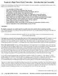
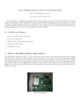
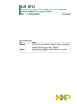
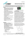
1
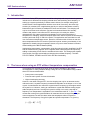
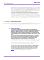
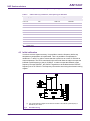
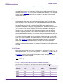
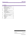
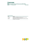
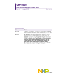
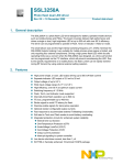
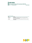
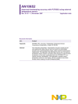
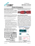
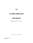
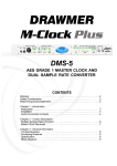
AN11247 Improved timekeeping accuracy with PCF85063, PCF8523 and PCF2123 using an external temperature sensor Rev. 1 — 17 December 2012 Application note Document information Info Content Keywords PCF85063, PCF8523, PCF2123, RTC, accuracy, timekeeping, temperature sensor, temperature compensation, crystal, 32.768 kHz Abstract The temperature dependent characteristics of quartz crystals prevent time keeping also with state-of-the-art real time clocks from being highly accurate over a wide temperature range, unless corrective measures are implemented. This application note describes how the use of an external temperature sensor, placed in a location which will be at or near the same temperature as the quartz crystal attached to the RTC, can improve accuracy considerably. If the application is already using a temperature sensor for some reason, only some extra firmware is needed without adding to the Bill Of Material (BOM). AN11247 NXP Semiconductors Improved timekeeping accuracy using an external temperature sensor Revision history Rev Date Description 01 20121217 Initial version, first release Contact information For additional information, please visit: http://www.nxp.com For sales office addresses, please send an email to: [email protected] AN11247_1 Application note All information provided in this document is subject to legal disclaimers. Rev. 1 — 17 December 2012 © NXP B.V. 2012. All rights reserved. 2 of 16 AN11247 NXP Semiconductors Improved timekeeping accuracy using an external temperature sensor 1. Introduction Real-time Clocks (RTC) have been around for a long time and many electronic systems include one for functions like keeping calendar time, tariff switching, time stamping, or waking up a system periodically to initiate certain actions, for example, doing some measurements. Not all applications need the same level of accuracy, but when high accuracy is necessary like in applications that rely on real time data where accuracy better than 5 ppm is needed, a standard RTC does not fulfil these. Time keeping can only be as accurate as its reference. Several environmental factors like humidity, vibration and pressure can influence RTC-accuracy but it is mainly the inferior characteristics of a quartz crystal over temperature, which result in deviations if temperature is changing. Several techniques have been used to improve the timekeeping accuracy achieved using 32.768 kHz crystals. This application note describes how the use of an external temperature sensor, placed in a location which will be at or near the same temperature as the RTC and its crystal can improve accuracy considerably. If the application is already using a temperature sensor, only some extra firmware is needed without adding to the Bill Of Material (BOM). Implementing temperature compensation using this method is highly simplified if the RTC has an electronic tuning register. Such a register allows influencing the clock speed by adding or subtracting counts from the oscillator divider chain. This changes the duration of the period of a single second without changing the oscillator frequency. The NXP RTCs PCF85063, PCF8563 and PCF2123 offer this functionality. 2. The issue when using an RTC without temperature compensation Time keeping can sometimes be done using the built in oscillator in the system microcontroller. In many situations though, using an RTC is unavoidable. Using a standalone RTC has several benefits: • Lower power consumption • Frees the main system for time-critical tasks • Higher timekeeping accuracy However, even when using an RTC, the time keeping can only be as accurate as the reference used. A crystal's frequency characteristic depends on the shape or 'cut' of the crystal. A manufacturer can control the crystal turnover frequency by the angle at which the crystal is cut. However, having to manufacture crystals with different cutting angles adds complexity and cost. A tuning fork crystal is usually cut in such a way that its frequency over temperature is a parabolic curve centered around 25 °C, see Fig 1. This means that a tuning fork crystal oscillator will resonate close to its target frequency at room temperature, but will slow down when the temperature either increases or decreases. The frequency of a typical crystal at a specific temperature T is given by: [ f = f 0 1 + B(T − T0 ) AN11247_1 Application note 2 ] All information provided in this document is subject to legal disclaimers. Rev. 1 — 17 December 2012 © NXP B.V. 2012. All rights reserved. 3 of 16 AN11247 NXP Semiconductors Improved timekeeping accuracy using an external temperature sensor Here f is the actual frequency, f0 is the frequency at room temperature, B is the parabolic coefficient, T is the temperature and T0 is the turnover temperature, marked by the top of the parabolic curve. Further, f0 can be considered to consist of two components as f 0 = f nom + f off Here fnom is the nominal frequency as specified and foff the offset from this nominal frequency which is a result of production spread, both at room temperature. [ ] 2 ⋅ 1 + B(T − T0 ) f − f nom ∆f The frequency deviation in ppm, can now be expressed as: = f nom f nom f = f nom + f off [ f off ∆f 2 2 = B(T − T0 ) + 1 + B(T − T0 ) f nom f nom Fig 1. ] (1) The deviation of frequency w.r.t. temperature of a typical 32.768 kHz crystal In equation (1) there are three variables that influence the frequency response as a function of temperature. These are the parabolic coefficient B, the turnover temperature T0 and the frequency offset foff at room temperature The crystal manufacturer specifies these parameters and typical values are T0 = 25°C, ∆T0 = ± 5°C and foff = 30 ppm. The coefficient B has a very small spread for various crystals of the same type, but it has the largest effect on the shape of the parabolic curve of the frequency deviation as a function AN11247_1 Application note All information provided in this document is subject to legal disclaimers. Rev. 1 — 17 December 2012 © NXP B.V. 2012. All rights reserved. 4 of 16 AN11247 NXP Semiconductors Improved timekeeping accuracy using an external temperature sensor of temperature. Variation in the turnover temperature T0 will shift the deviation curve left or right, variation in the offset at room temperature will shift it up or down. In practice the combination of variation in T0 and offset at room temperature easily causes an (in)accuracy of ±30 ppm at room temperature which corresponds to a time deviation of about 15 minutes per year. In addition, there is the effect of temperature. Typical values for B range from −0.035 ppm/°C² to −0.04 ppm/°C². In a real application, and using B = -0.04 means, that a clock built using a regular 32.768 kHz tuning fork crystal will at room temperature only have the frequency deviation resulting from the variations in T0 and foff. However, it will lose an additional two minutes per year at 10 degrees Celsius above (or below) room temperature and will lose an additional eight minutes per year at 20 degrees Celsius above (or below) room temperature. Two examples to get a better sense of the relationship between the real time and the deviation in ppm: • A clock running 1 s per day too fast has an inaccuracy of 1/(3600*24) = 11.57 ppm • A deviation of 1 s per week means 1.65 ppm 3. Possible solutions A few but not many options are available to improve the accuracy. Timekeeping accuracy can for example be improved through crystal screening, integrated crystals, keeping the crystal/RTC at a well specified temperature, or using a Temperature Compensated Crystal Oscillator (TXCO) like NXP’s PCF2127 and PCF2129. Crystal screening means to select only those crystals for which the offset foff falls within a narrower range than the normal production spread. This would need to be done by the crystal manufacturer, and limits the vertical shift of the parabolic curve within a narrower range. Besides adding to the cost, it does not alter the parabolic nature of the crystal’s frequency curve and only provides a small accuracy improvement at room temperature. Integrating the crystal in the same package as the RTC is a way of supplying RTC’s of which the performance is known. Usually a crystal screening will have taken place. It is also possible to measure foff during production and correct for it by programming a dedicated register in the RTC if such a register is implemented. It reduces the initial deviance at room temperature but as the previous option, it does nothing to alleviate the frequency deviation as a result of changing temperatures. Keeping the crystal within a narrow temperature range can be done by mounting the crystal in a temperature-controlled container but this will add considerable cost and complexity to the system. Another option is to use a 32.768 kHz temperature-compensated crystal oscillator (TCXO) as the clock source for a stand-alone RTC but obviously this will add cost too. The principle on which TCXOs are based is simple. Every crystal is optimized for a particular load capacitance. The value of this capacitance is included in the datasheet and deviations from this value will result in a shift in frequency of the oscillator. A TCXO uses this characteristic to implement a compensation mechanism. It includes a temperature sensor which measures the temperature at certain intervals. The device includes a lookup table and the temperature measurements in combination with the AN11247_1 Application note All information provided in this document is subject to legal disclaimers. Rev. 1 — 17 December 2012 © NXP B.V. 2012. All rights reserved. 5 of 16 AN11247 NXP Semiconductors Improved timekeeping accuracy using an external temperature sensor lookup table result in an output signal to apply a load-capacitance value for the integrated 32.768 kHz crystal to achieve high accuracy. Changing the load capacitance influences directly the oscillator frequency. It has the effect of flattening the parabolic curve, ideally to a perfectly straight horizontal line. By using an off-the-shelf TCXO, a high accuracy can be achieved without any development or calibration effort. Temperature compensation always implies measuring the temperature at which the crystal operates, at regular intervals. Then, according to the measured temperature, some action needs to be taken like adjustment of the crystal loading to the clock source as implemented in conventional TCXOs or using an algorithm which reads and updates registers in the RTC. The latter is the approach used in this application note for the NXP Real-Time Clocks with an electronic tuning register: PCF85063, PCF8523 and PCF2123. 4. The RTCs with a tuning register Since this application note deals specifically with the NXP RTCs which contain an electronic tuning or offset register (PCF85063, PCF8523, PCF2123) below a short introduction to these devices is given. 4.1 General Description The PCF85063, PCF8523 and PCF2123 are CMOS Real-Time Clock/calendars optimized for low power consumption. They contain a set of 8-bit registers with an autoincrementing address register, an on-chip 32.768 kHz oscillator with two integrated oscillator capacitors, a frequency divider which provides the source clock for the RealTime Clock/calendar (RTC), a programmable clock output and optionally a timer and an alarm. The Real-Time Clock family PCF85063 (three versions) is optimized for applications where very little space is available, but still contains the key features expected from a state of the art time reference. Typical applications are digital cameras, portable handheld gaming consoles, self care medical devices and printers/faxes. The PCF85063TP tracks time and date. Aside from electronic tuning, a frequency output 2 and an interrupt on every 30 s or 60 s can be enabled. It interfaces via a Fast-mode I Cbus. The PCF85063ATL and PCF85063BTL feature in addition an alarm facility and a 2 programmable countdown timer, controlled via either I C- or SPI-bus. The PCF2123 is an ultra low-power Real-Time Clock featuring the above mentioned features. It communicates via the SPI-bus with a maximum data rate of 6.25 Mbit/s. The PCF8523 is an ultra low-power Real-Time Clock which has in addition to the 2 PCF2123 an integrated battery back up circuit. It communicates via the I C-bus. Table 1 shows a quick comparison between the various types. AN11247_1 Application note All information provided in this document is subject to legal disclaimers. Rev. 1 — 17 December 2012 © NXP B.V. 2012. All rights reserved. 6 of 16 AN11247 NXP Semiconductors Improved timekeeping accuracy using an external temperature sensor Table 1. Comparison of target real time clocks Features PCF85063 family; tiny, low power PCF85063TP PCF85063ATL PCF85063BTL Ultra low power PCF2123 PCF8523 Unique features low power low power low power extremely low consumption, tiny consumption, tiny consumption, tiny power package package package consumption Type of interface IC IC SPI SPI IC Max. interface bus speed 400 kHz 400 kHz 8 MHz 6.25 MHz 1 MHz RAM 1 byte 1 byte 1 byte no no Year / leap year tracking yes / yes yes / yes yes / yes yes / yes yes / yes Year counter 2 digit 2 digit 2 digit 2 digit 2 digit (99 years) (99 years) (99 years) (99 years) (99 years) yes yes yes yes yes Programmable alarm and no (count down) timer functions yes yes yes yes Oscillator stop detector yes yes yes yes yes Battery back-up switch no no no no yes CLKOUT output push-pull push-pull push-pull open drain open drain (with CLKOE) (with CLKOE) (with CLKOE) Electronic tuning register 2 2 extremely low power consumption, battery back up 2 Programmable CLKOUT frequencies 32.768 kHz, 16.384 kHz, 8.192 kHz, 4.096 kHz, 2.048 kHz, 1.024 kHz, 1 Hz, off (CLKOUT=LOW) 32.768 kHz, 16.384 kHz, 8.192 kHz, 4.096 kHz, 2.048 kHz, 1.024 kHz, 1 Hz, off (CLKOUT=LOW) 32.768 kHz, 16.384 kHz, 8.192 kHz, 4.096 kHz, 2.048 kHz, 1.024 kHz, 1 Hz, off (CLKOUT = Hi-Z) 32.768 kHz, 16.384 kHz, 8.192 kHz, 4.096 kHz, 2.048 kHz, 1.024 kHz, 1 Hz, off (CLKOUT = Hi-Z) 32.768 kHz, 16.384 kHz, 8.192 kHz, 4.096 kHz, 1.024 kHz, 32 Hz, 1 Hz, off (CLKOUT = Hi-Z) 2 Integrated oscillator capacitors for CL = 7 pF or CL = 12.5 pF for CL = 7 pF or CL = 12.5 pF for CL = 7 pF or CL = 12.5 pF for CL = 7 pF for CL = 7 pF or CL = 12.5 pF Supply voltage range 1.8 V – 5.5 V 1.8 V – 5.5 V 1.8 V – 5.5 V 1.6 V – 5.5 V 1.6 V – 5.5 V Clock operating voltage 0.9 V – 5.5 V 0.9 V – 5.5 V 0.9 V – 6.0 V 1.1 V – 5.5 V 1.0 V – 5.5 V Typical current consumption 270 nA at VDD = 3 V 270 nA 270 nA 110 nA 150 nA Operating temperature range -40 °C to +85 °C -40 °C to +125 °C -40 °C to +85 °C -40 °C to +85 °C -40 °C to +85°C Packages HWSON8 HXSON10 U , HVQFN16, TSSOP14 [1] HXSON10 [1] [1] U , HVSON8, SO8, TSSOP14 Naked die AN11247_1 Application note All information provided in this document is subject to legal disclaimers. Rev. 1 — 17 December 2012 © NXP B.V. 2012. All rights reserved. 7 of 16 AN11247 NXP Semiconductors Improved timekeeping accuracy using an external temperature sensor For more detailed information about these devices, register structure and how to set them, please refer to the respective datasheets which are available at www.nxp.com. 4.2 Offset register The PCF85063, PCF8523 and PCF2123 incorporate an offset register which can be used to implement several functions, such as: • Accuracy tuning • Temperature compensation • Ageing adjustment The offset is made once every two hours in the normal mode (all types) or more frequent in the course mode. In course mode the offset is made for the: • PCF85063 every four minutes • PCF8523 once per minute • PCF2123 once per hour For PCF85063 and PCF8523, each LSB will introduce an offset of 4.34 ppm for the normal mode and 4.069 ppm for the course mode. The values of 4.34 ppm and 4.069 ppm are based on a nominal 32.768 kHz clock. The offset value is coded in two’s complement giving a range of +63 LSB to -64 LSB. Table 2. Offset values (in period time, not frequency) for PCF85063 and PCF8523 OFFSET[6:0] Offset value in decimal Offset value in ppm Normal mode Course mode 0111111 +63 +273.420 +256.347 0111110 +62 +269.080 +252.278 : : : : 0000010 +2 +8.680 +8.138 0000001 +1 +4.340 +4.069 0000000 [1] [1] 0 1111111 -1 -4.340 -4.069 1111110 -2 -8.680 -8.138 : : : : 1000001 -63 -273.420 -256.347 1000000 -64 -277.760 -260.416 [1] 0 [1] 0 Default value The correction is made by adding or subtracting clock correction pulses, thereby changing the period of a single second but not by changing the oscillator frequency. By adding clock pulses, the RTC is sped up (the crystal curve moves up). By subtracting clock pulses, the time slows down. Thus adding or subtracting clock pulses results in moving the curve in Fig 1 up or down in order to approach (ideally) 0 ppm accuracy at the given temperature. The offset values for PCF2123 are different and are given in Table 3. AN11247_1 Application note All information provided in this document is subject to legal disclaimers. Rev. 1 — 17 December 2012 © NXP B.V. 2012. All rights reserved. 8 of 16 AN11247 NXP Semiconductors Improved timekeeping accuracy using an external temperature sensor Table 3. Offset values (in period time, not frequency) for PCF2123 OFFSET[6:0] Offset value in decimal Offset value in ppm Normal mode Course mode 0111111 +63 +136.710 +273.420 0111110 +62 +134.540 +269.080 : : : : 0000010 +2 +4.340 +8.680 +1 +2.170 +4.340 0000001 0000000 [1] [1] 0 1111111 -1 -2.170 -4.340 1111110 -2 -4.340 -8.680 : : : : 1000001 -63 -136.710 -273.420 1000000 -64 -138.880 -277.760 [1] 0 [1] 0 Default value 4.3 Initial calibration In order to achieve highest accuracy, it is possible to tune the frequency before any temperature compensation is implemented. Thus it is possible to compensate for variations in T0 and foff in order to ensure that the crystal runs at or near 32.768 kHz at room temperature. The RTCs mentioned in this manual all have the option to output the buffered crystal frequency to the pin CLKOUT. In order to output the buffered crystal frequency at output CLKOUT, the CLKOUT signal has to be enabled and the CLKOUT frequency set to 32.768 kHz. The frequency can now be tuned using the electronic tuning register. (1) This typical application diagram shows CKLOUT enabled. The buffered crystal frequency is available at pin CLKOUT. Fig 2. AN11247_1 Application note Oscillator tuning All information provided in this document is subject to legal disclaimers. Rev. 1 — 17 December 2012 © NXP B.V. 2012. All rights reserved. 9 of 16 AN11247 NXP Semiconductors Improved timekeeping accuracy using an external temperature sensor If the required accuracy is within 1 second per day, a frequency counter with a resolution of at least 8 digits and an accuracy of 1 ppm is required. The accuracy of 1 ppm equals 32.768 mHz and thus if the clock is running at a nominal 32.768 kHz: • +1 ppm = 32768.0327 Hz; • -1 ppm = 32767.9673 Hz (1 day has 86400 s, 1s/day = 11.6 ppm). The oscillator should be tuned while the application is at the turnover temperature T0 of the crystal. The recommended workflow is given in Fig 3. In that example the clock runs by 14.6484 ppm too fast. A negative correction would maybe be expected, but the offset values in Table 2 and Table 3 refer to the period time instead of to the frequency. An increased oscillator frequency causes a shortened period time. Therefore the period time must be extended. This results in the positive correction pulse values. (1) The numbers in this example are valid only for PCF85063 and PCF8523 Fig 3. AN11247_1 Application note Offset calibration calculation workflow All information provided in this document is subject to legal disclaimers. Rev. 1 — 17 December 2012 © NXP B.V. 2012. All rights reserved. 10 of 16 AN11247 NXP Semiconductors Improved timekeeping accuracy using an external temperature sensor 5. Procedure to correct time deviations due to temperature variations In order to implement the temperature compensation algorithm described in this application note, a microcontroller (the system microcontroller) as well as an external temperature sensor to measure the ambient temperature are required. The temperature sensor must be located such that the measured temperature is a good representation of the crystal temperature. How often the temperature needs to be measured depends on the application and is a parameter to be chosen by the system designer. The microcontroller has now the additional task to initiate temperature measurement, determine the new tuning register value and to set this register in the RTC. The RTC needs to send an interrupt to the microcontroller on regular intervals, telling it to measure the temperature. If it is a low power application, where the microcontroller may be in standby, waking up the microcontroller (and the temperature sensor) obviously will increase power consumption. Thus how often this is done will be a compromise between accuracy requirements and power consumption. The interval should be chosen such, that the temperature is not expected to change much during the chosen timeframe. A value could be once per minute, or once per five minutes. In order to implement all steps correctly, details that have to be taken into account for the practical implementation are described in sections 5.1 until 5.3. 5.1 Step 1: Setting the timer The first step is to decide at which intervals the microcontroller should measure the temperature and set the timer accordingly. The RTCs described here have a freely programmable 8-bit countdown timer which can be used for this, except PCF85063TP which only offers the choice of a 30 s and a 1 minute interrupt. The timer control registers of the other RTCs determine the source clock frequency for the countdown timer and enable or disable the timer. The timer counts down from a software-loaded 8-bit binary value. At the end of every countdown, the timer sets the Timer Flag (TF). The bit TF may only be cleared by software. The asserted TF can be used to generate an interrupt (INT). Suppose that the RTC used is the PCF8523 and an interrupt to the microcontroller needs to be generated every 5 minutes. Further suppose that Timer B is used. This timer needs to be switched on by bit TBC in register Tmr_CLKOUT_ctrl at address 0Fh. The generation of interrupts is controlled via bit CTBIE (register Control_2) and should be set to enable Timer B. Register Tmr_B_reg (13h) would have to be loaded with 5, assuming a source clock frequency of 1/60 Hz which results in a clock giving one pulse per minute. This can be achieved by setting the bits TBQ[2:0] in register Tmr_B_freq_ctrl (at address 12h) to 011. This is just an example; other countdown frequencies can be selected as well as other time intervals. Refer to the datasheets for the control register settings for each type. 5.2 Step 2: Find the time deviation In order to get the time deviation that must be compensated for a given temperature, a lookup table or a second order equation (parabola) derived from measurements done during the development phase can be used. This table/equation should contain the deviation in ppm relative to the nominal conditions and is specific for the crystal used. If the type of crystal is changed, a new lookup table/equation is necessary. This can AN11247_1 Application note All information provided in this document is subject to legal disclaimers. Rev. 1 — 17 December 2012 © NXP B.V. 2012. All rights reserved. 11 of 16 AN11247 NXP Semiconductors Improved timekeeping accuracy using an external temperature sensor require quite some effort. Furthermore no compensation for the quartz crystal aging is included. For best results it is important to have an accurate initial tuning at the turn over temperature, see section 4.3. This correction method uses no feedback, so it is important to have a precise table or equation since any mistakes in this input will result in false compensation values. 5.2.1 Creating a lookup table or second order equation If the datasheet of the crystal used incorporates the parabolic curve and a table with these deviations, this can be used under the condition that the resolution of the data is high enough. Otherwise a high resolution frequency counter is necessary to measure and record how long a nominal 1s period out of the RTC actually takes when the crystal/RTC combination is subject to varying temperatures. In order to cover the whole temperature range for which the RTC is specified, measurements should be done from -40 °C to +85 °C. The oscillator frequency should not be measured by attaching the frequency meter to the OSCO pin which would add capacitance to this pin and thus detune the frequency with a Δf. In worst case the oscillator could even stop running. After the data has been collected, it can be put into an Excel spreadsheet from where the equation can be generated. A less time consuming method is to use the second order equation and the value for B given in the crystal’s datasheet. The production spread of B for a certain type of crystal is small. From equation (1) on page 4 the frequency deviation for a given temperature follows and with it the correction value can be calculated. The microcontroller can calculate the deviation between the results of this equation and the temperature measured. Alternatively the designer can create a lookup table from which the deviations are read. 5.2.2 Example Below such a lookup table is given for a crystal with B = −0.035 ppm/°C² and T0 = 25 °C for temperatures from -40 °C to +85 °C in steps of 5 °C. Tolerances in T0 and foff have not been taken into account and thus the equation used to calculate ∆f/f in Table 4 reduces to equation (2) below. For the lookup table, only the columns “Temperature T” and “Offset value in decimal” are relevant. ∆f = B (T − T0 ) 2 f nom (2) Table 4. Example lookup table (only valid for PCF85063 and PCF8523) Only the columns “Temperature T” and”Offset value in decimal” need to be included Parabolic coefficient B Temperature T Temperature offset Deviation [ppm/°C ] [°C] [°C] [ppm] (normal mode) -0.035 -40 -65 -147.88 -34 -0.035 -35 -60 -126.00 -29 -0.035 -30 -55 -105.88 -24 2 AN11247_1 Application note All information provided in this document is subject to legal disclaimers. Rev. 1 — 17 December 2012 ∆f/f Offset value in decimal © NXP B.V. 2012. All rights reserved. 12 of 16 AN11247 NXP Semiconductors Improved timekeeping accuracy using an external temperature sensor Parabolic coefficient B Temperature T Temperature offset Deviation [ppm/°C ] [°C] [°C] [ppm] (normal mode) -0.035 -25 -50 -87.50 -20 -0.035 -20 -45 -70.88 -16 -0.035 -15 -40 -56.00 -13 -0.035 -10 -35 -42.88 -10 -0.035 -5 -30 -31.50 -7 -0.035 0 -25 -21.88 -5 -0.035 5 -20 -14.00 -3 -0.035 10 -15 -7.88 -2 -0.035 15 -10 -3.50 -1 -0.035 20 -5 -0.88 0 -0.035 25 0 0.00 0 -0.035 30 5 -0.88 0 -0.035 35 10 -3.50 -1 -0.035 40 15 -7.88 -2 -0.035 45 20 -14.00 -3 -0.035 50 25 -21.88 -5 -0.035 55 30 -31.50 -7 -0.035 60 35 -42.88 -10 -0.035 65 40 -56.00 -13 -0.035 70 45 -70.88 -16 -0.035 75 50 -87.50 -20 -0.035 80 55 -105.88 -24 -0.035 85 60 -126.00 -29 2 ∆f/f Offset value in decimal 5.3 Step 3: update the electronic tuning register In the previous step the required setting for the electronic tuning register (programmable offset register) for compensating varying temperatures was found. This value must not directly be written in the register, because in section 4.3 “Initial calibration” the correct clock speed for the turnover temperature was set. Directly writing into the offset register would overwrite this setting. Therefore, the value found in the look up table must be added to the already programmed initial setting and this value must be written into the offset register. AN11247_1 Application note All information provided in this document is subject to legal disclaimers. Rev. 1 — 17 December 2012 © NXP B.V. 2012. All rights reserved. 13 of 16 AN11247 NXP Semiconductors Improved timekeeping accuracy using an external temperature sensor 6. NXP Demonstration board OM6297 A fast way to start developing an algorithm and test its working is possible by using the NXP demonstration board OM6297. This board was designed to illustrate the operation of an ultra low power SPI based real time clock (PCF2123) along with an industry standard 8-character alphanumeric LCD and an LM75B temperature sensor. The microcontroller chosen for this application is the NXP P89LPC932A1, which is a single-chip microcontroller available in various packages. In the RTC demo board, the PLCC28 package is used. The LPC932 is based on a high performance architecture which works at up to six times the rate of standard 80C51 devices. The LPC932 has many integrated functions to reduce component count, board space, and system cost. It offers 8KB of on-chip flash code memory, 768 bytes of data RAM along with 512 bytes of data EEPROM storage, and supports hardware I2C-bus and SPI-bus for communication. The LPC932 supports multiple additional I/O channels, counters/timers, PWM’s, and analog comparators. Please see the datasheet for full details. The available temperature sensor is the NXP LM75BD in a standard SO8 package. The LM75B is a pin for pin replacement for the industry standard LM75 and LM75A with an improved temperature resolution of 0.125 °C. It has a wide supply range, and an I2C-bus interface. Temperatures can range from −55 °C to +125 °C with programmable temperature thresholds. The LM75B is ideal for low-power designs, as it only uses a current of 1.0 μA in standby mode. With both the RTC and temperature sensor onboard, it is easy to start developing an application and implementing the algorithm as described here. The LCD driver chosen is the NXP PCF8562 in a plastic 48 pin TSSOP package. The PCF8562 has a wide supply voltage range, an I2C-bus interface for commands and control and can drive up to 128-segments using a 1:4 multiplex rate. The board also contains a 10-pin header that allows the LPC932A1 to be reprogrammed using serial ICP (In Circuit Programming) from a PC. A simple ICP programmer called USB-ICP is available from Future Designs, Inc. to allow any PC with a USB port to easily program the LCD demo board. The USBICP also supports other NXP microcontrollers that use standard ICP programming. Please consult FDI’s website for more details on USB-ICP. 7. References The documents listed below provide further useful information. They are available at NXP’s website www.nxp.com. AN11247_1 Application note a. Product data sheets PCF85063. b. Product data sheet PCF8523. c. Product data sheet PCF2123. d. AN10652; Improved timekeeping accuracy with PCF8563 using external temperature sensor, Rev 1, 2 November 2007. e. UM10301; User Manual for NXP Real Time Clocks, Rev 1, 23 December 2008. f. UM10204; I C-bus specification and user manual. Rev 4, 13 February 2012. 2 All information provided in this document is subject to legal disclaimers. Rev. 1 — 17 December 2012 © NXP B.V. 2012. All rights reserved. 14 of 16 AN11247 NXP Semiconductors Improved timekeeping accuracy using an external temperature sensor 8. Legal information 8.1 Definitions Draft — The document is a draft version only. The content is still under internal review and subject to formal approval, which may result in modifications or additions. NXP Semiconductors does not give any representations or warranties as to the accuracy or completeness of information included herein and shall have no liability for the consequences of use of such information. 8.2 Disclaimers Limited warranty and liability — Information in this document is believed to be accurate and reliable. However, NXP Semiconductors does not give any representations or warranties, expressed or implied, as to the accuracy or completeness of such information and shall have no liability for the consequences of use of such information. In no event shall NXP Semiconductors be liable for any indirect, incidental, punitive, special or consequential damages (including - without limitation lost profits, lost savings, business interruption, costs related to the removal or replacement of any products or rework charges) whether or not such damages are based on tort (including negligence), warranty, breach of contract or any other legal theory. Notwithstanding any damages that customer might incur for any reason whatsoever, NXP Semiconductors’ aggregate and cumulative liability towards customer for the products described herein shall be limited in accordance with the Terms and conditions of commercial sale of NXP Semiconductors. Right to make changes — NXP Semiconductors reserves the right to make changes to information published in this document, including without limitation specifications and product descriptions, at any time and without notice. This document supersedes and replaces all information supplied prior to the publication hereof. Applications — Applications that are described herein for any of these products are for illustrative purposes only. NXP Semiconductors makes no representation or warranty that such applications will be suitable for the specified use without further testing or modification. Customers are responsible for the design and operation of their applications and products using NXP Semiconductors products, and NXP Semiconductors accepts no liability for any assistance with applications or customer product design. It is customer’s sole responsibility to determine whether the NXP Semiconductors product is suitable and fit for the customer’s applications and products planned, as well as for the planned application and use of customer’s third party customer(s). Customers should provide appropriate design and operating safeguards to minimize the risks associated with their applications and products. NXP Semiconductors does not accept any liability related to any default, damage, costs or problem which is based on any weakness or default in the customer’s applications or products, or the application or use by customer’s third party customer(s). Customer is responsible for doing all necessary testing for the customer’s applications and products using NXP Semiconductors products in order to avoid a default of the applications and the products or of the application or use by customer’s third party customer(s). NXP does not accept any liability in this respect. Translations — A non-English (translated) version of a document is for reference only. The English version shall prevail in case of any discrepancy between the translated and English versions. Export control — This document as well as the item(s) described herein may be subject to export control regulations. Export might require a prior authorization from competent authorities. 8.3 Trademarks Notice: All referenced brands, product names, service names and trademarks are property of their respective owners. Suitability for use — NXP Semiconductors products are not designed, authorized or warranted to be suitable for use in life support, life-critical or safety-critical systems or equipment, nor in applications where failure or malfunction of an NXP Semiconductors product can reasonably be expected to result in personal injury, death or severe property or environmental damage. NXP Semiconductors accepts no liability for inclusion and/or use of NXP Semiconductors products in such equipment or applications and therefore such inclusion and/or use is at the customer’s own risk. AN11247_1 Application note All information provided in this document is subject to legal disclaimers. Rev. 1 — 17 December 2012 © NXP B.V. 2012. All rights reserved. 15 of 16 AN11247 NXP Semiconductors Improved timekeeping accuracy using an external temperature sensor 9. Contents 1. 2. 3. 4. 4.1 4.2 4.3 5. 5.1 5.2 5.2.1 5.2.2 5.3 6. 7. 8. 8.1 8.2 8.3 9. Introduction ......................................................... 3 The issue when using an RTC without temperature compensation ................................ 3 Possible solutions............................................... 5 The RTCs with a tuning register ........................ 6 General Description ........................................... 6 Offset register..................................................... 8 Initial calibration ................................................. 9 Procedure to correct time deviations due to temperature variations ...................................... 11 Step 1: Setting the timer................................... 11 Step 2: Find the time deviation ......................... 11 Creating a lookup table or second order equation ......................................................................... 12 Example ........................................................... 12 Step 3: update the electronic tuning register .... 13 NXP Demonstration board OM6297 ................. 14 References ......................................................... 14 Legal information .............................................. 15 Definitions ........................................................ 15 Disclaimers....................................................... 15 Trademarks ...................................................... 15 Contents ............................................................. 16 Please be aware that important notices concerning this document and the product(s) described herein, have been included in the section 'Legal information'. © NXP B.V. 2012. All rights reserved. For more information, please visit: http://www.nxp.com For sales office addresses, please send an email to: [email protected] Date of release: 17 December 2012 Document identifier: AN11247_1