1
s
Preface, Contents
SIMATIC
Process Control System PCS 7
SIMATIC Route Control
Manual
What's New
1
Product Introduction
2
Getting Started
3
ES Route Control Configuration
4
Block Library
5
Configuration Guide
6
OS Operator Control and
Monitoring
7
Dialogs / Interfaces
A
Abbreviations
B
Glossary, Index
Edition 07/2005
A5E00343836-02
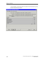
Safety Guidelines
This manual contains notices you have to observe in order to ensure your personal safety, as well as to
prevent damage to property. The notices referring to your personal safety are highlighted in the manual
by a safety alert symbol, notices referring to property damage only have no safety alert symbol. The
notices shown below are graded according to the degree of danger.
Danger
!
indicates that death or severe personal injury will result if proper precautions are not taken.
!
indicates that death or severe personal injury may result if proper precautions are not taken.
!
Warning
Caution
with a safety alert symbol indicates that minor personal injury can result if proper precautions are not
taken.
Caution
without a safety alert symbol indicates that property damage can result if proper precautions are not
taken.
Attention
indicates that an unintended result or situation can occur if the corresponding notice is not taken into
account.
If more than one degree of danger is present, the warning notice representing the highest degree of
danger will be used. A notice warning of injury to persons with a safety alert symbol may also include a
warning relating to property damage.
Qualified Personnel
The device/system may only be set up and used in conjunction with this documentation. Commissioning
and operation of a device/system may only be performed by qualified personnel. Within the context of
the safety notices in this documentation qualified persons are defined as persons who are authorized to
commission, ground and label devices, systems and circuits in accordance with established safety
practices and standards.
Prescribed Usage
Note the following:
!
Warning
This device and its components may only be used for the applications described in the catalog or the
technical description, and only in connection with devices or components from other manufacturers
which have been approved or recommended by Siemens.
Correct, reliable operation of the product requires proper transport, storage, positioning and assembly
as well as careful operation and maintenance.
Trademarks
All names identified by ® are registered trademarks of the Siemens AG.
The remaining trademarks in this publication may be trademarks whose use by third parties for their
own purposes could violate the rights of the owner.
Copyright Siemens AG 2005 All rights reserved
Disclaimer of Liability
The distribution and duplication of this document or the utilization
and transmission of its contents are not permitted without express
written permission. Offenders will be liable for damages. All rights,
including rights created by patent grant or registration of a utility
model or design, are reserved
We have reviewed the contents of this publication to ensure
consistency with the hardware and software described. Since
variance cannot be precluded entirely, we cannot guarantee full
consistency. However, the information in this publication is
reviewed regularly and any necessary corrections are included
in subsequent editions.
Siemens AG
Automation and Drives
Postfach 4848, 90327 Nuremberg, Germany
Siemens AG 2005
Technical data subject to change.
Siemens Aktiengesellschaft
A5E00343836-02
Preface
Purpose of This Manual
This manual provides a comprehensive overview of programming with
SIMATIC ROUTE CONTROL. It will help you install and commission this software.
Procedures for program creation, user program setup, and the language elements
are presented.
This manual is intended for programmers and persons involved in project planning,
commissioning, and servicing of automation systems.
We recommend that you familiarize yourself with the examples in Chapter 6
"Guide to Project Planning. "This will help you get started with programming of
SIMATIC ROUTE CONTROL.
Basic Knowledge Required
Basic knowledge of automation engineering is required to understand this manual.
In addition, knowledge of how to use computers or PC-like equipment (such as
programming devices) in the Windows 95/98/2000 or NT/XP operating systems is
assumed. Because SIMATIC ROUTE CONTROL is based on the STEP 7 / PCS 7
basic software, you should also know how to work with this basic software. For this
information, consult the manual entitled "Programming with STEP 7 / PCS 7.”
Scope of This Manual
This manual is valid for the SIMATIC ROUTE CONTROL V6.1 software package.
Changes from the Previous Version
As compared to the previous version, this documentation also contains the
following enhancements for ROUTE CONTROL V6.1:
•
Maintenance safety
•
Operating systems
•
SIMATIC S7 417-H
•
HW Configuration
Process Control System PCS 7 - SIMATIC Route Control
A5E00343836-02
iii
Preface
Further Support
If you have any technical questions, please get in touch with your Siemens
representative or agent responsible.
You will find your contact person at:
http://www.siemens.com/automation/partner
You will find a guide to the technical documentation offered for the individual
SIMATIC Products and Systems here at:
http://www.siemens.com/simatic-tech-doku-portal
The online catalog and order system is found under:
http://www.mall.ad.siemens.com/
Training Centers
Siemens offers a number of training courses to familiarize you with the
Process Control System PCS 7. Please contact your regional training center or our
central training center in D 90327 Nuremberg, Germany for details:
Telephone: +49 (911) 895-3200.
Internet:
iv
http://www.sitrain.com
Process Control System PCS 7 - SIMATIC Route Control
A5E00343836-02
Preface
Technical Support
You can reach the Technical Support for all A&D products
•
Via the Web formula for the Support Request
http://www.siemens.com/automation/support-request
•
Phone:
+ 49 180 5050 222
•
Fax:
+ 49 180 5050 223
Additional information about our Technical Support can be found on the Internet
pages http://www.siemens.com/automation/service
Service & Support on the Internet
In addition to our documentation, we offer our Know-how online on the internet at:
http://www.siemens.com/automation/service&support
where you will find the following:
•
The newsletter, which constantly provides you with up-to-date information on
your products.
•
The right documents via our Search function in Service & Support.
•
A forum, where users and experts from all over the world exchange their
experiences.
•
Your local representative for Automation & Drives.
•
Information on field service, repairs, spare parts and more under "Services".
Process Control System PCS 7 - SIMATIC Route Control
A5E00343836-02
v
Preface
vi
Process Control System PCS 7 - SIMATIC Route Control
A5E00343836-02
Contents
1
What's New
1.1
1.2
1.3
1.4
1.5
2
1-1
Welcome...................................................................................................... 1-1
What's New in SIMATIC Route Control V6.0? ............................................ 1-2
What's New in SIMATIC Route Control V6.0 SP1 ? ................................... 1-7
What's New in SIMATIC Route Control V6.1? ............................................ 1-8
What's New in SIMATIC Route Control V6.1 SP1 ? ................................. 1-10
Product Introduction
2.1
2.1.1
2.1.2
2.1.3
2.2
2.2.1
2.2.2
2.2.3
2.2.4
2.2.5
2.2.6
2.2.7
2.2.8
2.3
2.3.1
2.3.2
2.3.3
2.4
2.4.1
2.4.2
2.4.2.1
2.4.3
2.4.3.1
2.4.4
2.4.4.1
2.4.4.2
2.4.4.3
2.4.5
2.4.5.1
2.4.5.2
2.4.5.3
2.4.5.4
2.4.5.5
2.4.6
2.4.6.1
2.4.6.2
2.4.6.3
2.4.6.4
2.4.6.5
2-1
Route Control............................................................................................... 2-1
What Is Route Control? ............................................................................... 2-1
Functions of Route Control.......................................................................... 2-3
Migration of Older Projects .......................................................................... 2-3
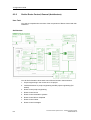
Components of Route Control ..................................................................... 2-4
Overview...................................................................................................... 2-4
Route Control Library .................................................................................. 2-4
Route Control Project Engineering.............................................................. 2-5
Route Control Wizard .................................................................................. 2-6
Route Control Server................................................................................... 2-6
Route Control Center................................................................................... 2-6
Route Control Faceplate.............................................................................. 2-7
Route Control Route Log............................................................................. 2-7
Configuration Possibilities ........................................................................... 2-8
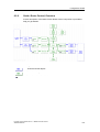
Client/Server Architecture of Route Control ................................................ 2-8
Distribution of Route Control Applications................................................... 2-8
MES Interface .............................................................................................. 2-9
Installation.................................................................................................. 2-10
Readme File with Updated Information ..................................................... 2-10
Delivery Form ............................................................................................ 2-10
Delivery Form of Route Control ................................................................. 2-10
Setup ......................................................................................................... 2-11
Installing Route Control Components........................................................ 2-11
Installation Requirements .......................................................................... 2-12
Hardware and Software (ES, OS) ............................................................. 2-12
Hardware and Software (AS)..................................................................... 2-14
Dependence on Other Components.......................................................... 2-14
Authorization.............................................................................................. 2-16
Authorization (Overview) ........................................................................... 2-16
Required Authorization .............................................................................. 2-17
Installing an Authorization ......................................................................... 2-18
Missing Authorizations............................................................................... 2-19
Missing Authorization for Route Control Server ........................................ 2-19
User Authorizations ................................................................................... 2-20
Authorization Management........................................................................ 2-20
Action when Logon Component Is Not Installed ....................................... 2-20
Introduction to Authorization Management................................................ 2-21
User Roles for Route Control .................................................................... 2-21
Defining User Authorizations ..................................................................... 2-24
Process Control System PCS 7 - SIMATIC Route Control
A5E00343836-02
iii
Contents
3
Getting Started
3.1
3.2
3.2.1
3.2.2
3.2.3
3.2.4
3.3
3.3.1
3.3.2
3.3.3
3.3.4
3.3.5
3.3.6
3.3.7
3.3.8
3.3.9
3.3.10
3.3.11
3.3.12
3.3.13
3.3.14
3.3.15
3.3.16
3.4
3.4.1
3.4.2
3.4.3
3.4.4
3.5
3.5.1
3.5.2
3.5.3
3.6
3.6.1
3.6.2
3.6.3
3.6.4
4
iv
Getting Started ............................................................................................ 3-1
Important Notes ........................................................................................... 3-3
Restriction of Quantity Framework .............................................................. 3-3
Clearing/Resetting a WinCC OS ................................................................. 3-4
Enabling Changes ....................................................................................... 3-4
SIMATIC BATCH and Route Control .......................................................... 3-4
Libraries & Blocks........................................................................................ 3-5
PLCSim........................................................................................................ 3-5
Downloading Blocks to the AS (User Blocks).............................................. 3-5
Downloading Blocks to the AS (Instance DB) ............................................. 3-6
Renaming a Process Cell or a Unit in the Plant Hierarchy.......................... 3-7
Adapting the Block Ranges (CFC) .............................................................. 3-7
Optimization: Memory Requirements in the AS .......................................... 3-7
Error Message for the SCL Compiler (CFC) ............................................... 3-9
Installing a New Route Control Library...................................................... 3-11
Copying RC_IF_ROUTE Route Blocks ..................................................... 3-11
Reserved Ranges/Block Number Limit ..................................................... 3-11
Procedure for Creating a New S7 Project with Route Control .................. 3-12
RC_IF_SFC (FB849) - Online Help ........................................................... 3-12
BSEND/BRCV vs. PUT ............................................................................. 3-12
STEP 7 Import/Export Assistant ................................................................ 3-13
LOCK Input on Element Blocks ................................................................. 3-13
Optimizing the Number of WinCC Tags .................................................... 3-13
Wizard........................................................................................................ 3-14
Route Control Wizard: Start Requirements ............................................... 3-14
Route Control Wizard: Same Properties as Industrial Ethernet ................ 3-15
Specifying the RC Server Computer Name and IP Address..................... 3-15
Chart-in-Chart Technology ........................................................................ 3-16
Configuration ............................................................................................. 3-17
Shared Directory 'RC_LOAD' on the RC Server ....................................... 3-17
Location as a Variant................................................................................. 3-17
Downloading the Server during an Active Route....................................... 3-18
WinCC / Operation & Monitoring ............................................................... 3-19
Dynamic Wizard/Compiling the Script File for the RC Dynamic Wizard ... 3-19
Additional Installation of RC Software, WinCC RC Faceplate .................. 3-19
Operating an RC Faceplate on an RC Server........................................... 3-20
Online Help in the Route Control Center................................................... 3-20
ES Route Control Configuration
4.1
4.1.1
4.1.2
4.1.3
4.1.4
4.1.5
4.1.6
4.1.7
3-1
4-1
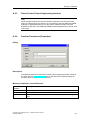
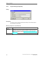
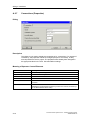
Configuration Preparation............................................................................ 4-1
Migration ...................................................................................................... 4-1
Block Changes ............................................................................................ 4-2
Migration Steps............................................................................................ 4-3
Migration of "RCS-Based-on-PCS 7 Projects" ............................................ 4-3
Migration of "RCS-Based-on-BRAUMAT Projects" ..................................... 4-4
Migration V6.0 to V6.1 ................................................................................. 4-5
Migration V6.1 to V6.1 SP1 ......................................................................... 4-6
Process Control System PCS 7 - SIMATIC Route Control
A5E00343836-02
Contents
5
Block Library
5.1
5.2
5.3
5.3.1
5.3.2
5.4
5.4.1
5.5
5.5.1
5.5.2
5.5.3
5.5.4
5.5.5
5.5.6
5.5.7
5.5.8
5.5.9
5.5.10
5.6
5.6.1
5.6.2
5.6.3
5.6.4
5.6.5
5.6.6
5.6.7
5.6.8
5.7
5.7.1
5.7.2
5.7.3
5.8
5.8.1
5.8.2
5.8.3
5.9
5.9.1
5.10
5.10.1
5.10.2
5.10.3
5.11
5.11.1
5.11.2
5.11.3
5.11.4
5.11.5
5.11.6
5.12
5.12.1
5.12.2
5.12.2.1
5.12.2.2
5.12.2.3
5.12.2.4
5-1
Route Control Blocks................................................................................... 5-1
Route Control Blocks (General)................................................................... 5-3
User Interface .............................................................................................. 5-5
Overview...................................................................................................... 5-5
Example of User-Defined Type ................................................................... 5-6
Configuration ............................................................................................... 5-8
RC_IF_CFG (FB850)................................................................................... 5-8
Routes ....................................................................................................... 5-16
RC_IF_ROUTE (FB800)............................................................................ 5-16
RC_IF_ROUTE.QREC_STA ..................................................................... 5-35
RC_IF_ROUTE.QRET_VAL...................................................................... 5-36
RC_IF_ROUTE.QMAT_DIAG ................................................................... 5-38
RC_IF_ROUTE.GETXDIAG ...................................................................... 5-39
RC_IF_ROUTE.QDIAG ............................................................................. 5-40
Example Using QRESTPOS and QRPOSERR......................................... 5-41
RC_IF_ENCODER (FC800) ...................................................................... 5-42
RC_IF_DECODER (FC801) ...................................................................... 5-44
RC_IF_ROUTE: Simulated Idle State ....................................................... 5-46
Control Elements ....................................................................................... 5-47
RC_IF_MOT_REV (FB823)....................................................................... 5-47
RC_IF_MOT_SPED (FB824) .................................................................... 5-51
RC_IF_VAL_MOT (FB825) ....................................................................... 5-55
RC_IF_MOTOR (FB822)........................................................................... 5-59
RC_IF_VALVE (FB826)............................................................................. 5-63
RC_IF_USER_CE (FB829) ....................................................................... 5-67
Control Bit Assignment .............................................................................. 5-71
Feedback Bit Assignment.......................................................................... 5-71
Sensor Elements ....................................................................................... 5-72
RC_IF_SENSOR (FB845) ......................................................................... 5-72
RC_IF_CONDUCT (FB846) ...................................................................... 5-74
RC_IF_USER_SE (FB848) ....................................................................... 5-77
Parameter Elements.................................................................................. 5-79
RC_IF_VOLUME (FC808)......................................................................... 5-80
RC_IF_TIMER (FC809)............................................................................. 5-81
RC_IF_USER_PE (FC807) ....................................................................... 5-82
Connection Elements ................................................................................ 5-84
RC_IF_LE (FB828).................................................................................... 5-84
Cross-Coupling .......................................................................................... 5-86
Overview of Cross-Coupling Blocks .......................................................... 5-86
RC_IF_XC_DIAG (FB884) ........................................................................ 5-86
RC_IF_XC_LIFE (FC884) ......................................................................... 5-91
Remote Elements ...................................................................................... 5-92
Overview of Remote Blocks ...................................................................... 5-92
RC_IF_REMOTE_CE (FB821).................................................................. 5-93
RC_IF_REMOTE_PE (FB843) .................................................................. 5-97
RC_IF_REMOTE_SE (FB842) ................................................................ 5-101
RC_IF_REMOTE_RECV (FB833)........................................................... 5-104
RC_IF_REMOTE_SEND (FB831)........................................................... 5-107
Kernel Blocks........................................................................................... 5-110
Overview of Kernel Blocks....................................................................... 5-110
Data Blocks (DB) ..................................................................................... 5-111
RC_CE_FIELD (DB99)............................................................................ 5-111
RC_CFG (DB100) ................................................................................... 5-111
RC_DATA_TG34_36 (DB405) ................................................................ 5-111
RC_FIFO1 (DB870)................................................................................. 5-111
Process Control System PCS 7 - SIMATIC Route Control
A5E00343836-02
v
Contents
5.12.2.5
5.12.2.6
5.12.2.7
5.12.2.8
5.12.2.9
5.12.2.10
5.12.2.11
5.12.2.12
5.12.2.13
5.12.2.14
5.12.2.15
5.12.2.16
5.12.2.17
5.12.2.18
5.12.2.19
5.12.2.20
5.12.2.21
5.12.3
5.12.3.1
5.12.3.2
5.12.3.3
5.12.3.4
5.12.3.5
5.12.3.6
5.12.3.7
5.12.3.8
5.12.3.9
5.12.3.10
5.12.3.11
5.12.3.12
5.12.3.13
5.12.3.14
5.12.3.15
5.12.3.16
5.12.3.17
5.12.3.18
5.12.3.19
5.12.3.20
5.12.3.21
5.12.3.22
5.12.3.23
5.12.4
5.12.4.1
5.12.4.2
5.12.4.3
5.12.4.4
5.12.4.5
5.12.4.6
5.12.4.7
5.12.4.8
5.12.4.9
5.12.4.10
5.12.4.11
5.12.4.12
5.12.4.13
5.12.4.14
5.12.4.15
vi
RC_FIFO1_SE (DB874) .......................................................................... 5-111
RC_FIFO4 (DB890)................................................................................. 5-111
RC_FIFO4_SE (DB894) .......................................................................... 5-112
RC_IDB_SEND_FIFO1 (DB590)............................................................. 5-112
RC_IDB_SEND_FIFO4 (DB593)............................................................. 5-112
RC_LE_FIELD (DB96) ............................................................................ 5-112
RC_PE_FIELD (DB97) ............................................................................ 5-112
RC_REMOTE1 to RC_REMOTE5 (DB91 to DB95)................................ 5-112
RC_ROUTE1 to RC_ROUTE300 (DB101 to DB400) ............................. 5-113
RC_SE_FIELD (DB98) ............................................................................ 5-113
RC_SYS_DB (DB410)............................................................................. 5-113
RC_TG34_TG36_DB (DB404) ................................................................ 5-113
RC_XC_1 to RC_XC_31 (DB751 to DB781)........................................... 5-113
RC_XC_JOB (DB705) ............................................................................. 5-113
RC_XC_JOB_START (DB450) ............................................................... 5-114
RC_XC_PCU (DB704) ............................................................................ 5-114
RC_XC_PUTX_1 to RC_XC_PUTX_31 (DB451 to DB481) ................... 5-114
User-Defined Types (UDT)...................................................................... 5-115
RC_ANY_UDT (UDT506)........................................................................ 5-115
RC_CE_FIELD_UDT (UDT99) ................................................................ 5-115
RC_EXT_PE_ACTV (UDT103) ............................................................... 5-115
RC_FIFO_UDT (UDT670) ....................................................................... 5-115
RC_LE_FIELD_UDT (UDT96)................................................................. 5-115
RC_PE_FIELD_UDT (UDT97) ................................................................ 5-115
RC_RE_INFO_UDT (UDT109)................................................................ 5-116
RC_RE_UDT (UDT100) .......................................................................... 5-116
RC_REM_CESEPE (UDT104) ................................................................ 5-116
RC_REQUEST_BUFFER_UDT (UDT111) ............................................. 5-116
RC_ROUTE_CFG (UDT105) .................................................................. 5-116
RC_ROUTE_CM_UDT (UDT110) ........................................................... 5-116
RC_ROUTE_TB_UDT (UDT102) ............................................................ 5-117
RC_SE_FIELD_UDT (UDT98) ................................................................ 5-117
RC_SEPU_UDT (UDT674) ..................................................................... 5-117
RC_SYS_UDT (UDT120) ........................................................................ 5-117
RC_XC_JOB_UDT (UDT705) ................................................................. 5-117
RC_XC_PCU_UDT (UDT704)................................................................. 5-117
RC_XC_PUT_DB_UDT (UDT452).......................................................... 5-118
RC_XC_PUT_SD_UDT (UDT684).......................................................... 5-118
RC_XC_PUT_UDT (UDT683) ................................................................. 5-118
RC_XC_PUTX_UDT (UDT451)............................................................... 5-118
RC_XC_UDT (UDT101) .......................................................................... 5-118
Function Blocks (FC) ............................................................................... 5-119
RC_ATTRIB_PTR (FC860) ..................................................................... 5-119
RC_CALL_KILLER (FC814).................................................................... 5-119
RC_DB_AREA_COPY (FC862) .............................................................. 5-119
RC_FC_COPY (FC863) .......................................................................... 5-119
RC_FIFO_DEBUG_SEND (FC891) ........................................................ 5-119
RC_FIFO_INPUT_FC (FC890) ............................................................... 5-119
RC_FIFO_SEND (FC803) ....................................................................... 5-120
RC_KERNEL_CALL (FC804).................................................................. 5-120
RC_LE_DGRAMM (FC825) .................................................................... 5-120
RC_LOAD_AR1 (FC861) ........................................................................ 5-120
RC_MASTER_CREATE_ERR (FC851).................................................. 5-120
RC_MAT (FC836).................................................................................... 5-120
RC_PE_COMMON (FC810).................................................................... 5-121
RC_ROUTE_CE_ERR (FC812) .............................................................. 5-124
RC_ROUTE_PE_DGRAM (FC822) ........................................................ 5-124
Process Control System PCS 7 - SIMATIC Route Control
A5E00343836-02
Contents
5.12.4.16
5.12.4.17
5.12.4.18
5.12.4.19
5.12.4.20
5.12.4.21
5.12.4.22
5.12.4.23
5.12.4.24
5.12.4.25
5.12.5
5.12.5.1
5.12.5.2
5.12.5.3
5.12.5.4
5.12.5.5
5.12.5.6
5.12.5.7
5.12.5.8
5.12.5.9
5.12.5.10
5.12.5.11
5.12.5.12
5.12.5.13
5.12.5.14
5.12.5.15
5.12.5.16
5.12.5.17
5.12.5.18
5.12.5.19
5.12.5.20
5.12.5.21
5.12.5.22
5.12.5.23
5.12.5.24
5.12.5.25
5.12.5.26
5.12.5.27
5.12.5.28
5.12.5.29
5.12.5.30
5.12.5.31
5.12.5.32
5.12.5.33
5.12.5.34
5.12.5.35
5.12.5.36
5.12.5.37
5.12.5.38
5.12.5.39
5.12.5.40
5.12.5.41
5.12.5.42
RC_ROUTE_SE_ERR (FC813)............................................................... 5-125
RC_TG34_03 (FC811) ............................................................................. 5-125
RC_UPD_CESEPE (FC823).................................................................... 5-125
RC_UPD_CESEPE_EX (FC824)............................................................. 5-125
RC_XC_CALL (FC805) ............................................................................ 5-125
RC_XC_JOB_USER (FC885).................................................................. 5-125
RC_XC_PUTX_RECV (FC882) ............................................................... 5-126
RC_XC_PUTX_SEND (FC881) ............................................................... 5-126
RC_XFER_LE (FC826) ............................................................................ 5-126
RC_XFER_MON_FLT (FC829) ............................................................... 5-126
Function Blocks (FB) ............................................................................... 5-127
RC_CALL_DIAG (FB851)........................................................................ 5-127
RC_CE_COMMON (FB827).................................................................... 5-127
RC_CLOCK (FB899) ............................................................................... 5-131
RC_MASTER_BUFFER (FB856) ............................................................ 5-131
RC_MASTER_FUNC (FB852) ................................................................ 5-132
RC_MASTER_MATERIAL (FB860) ........................................................ 5-132
RC_MASTER_MSG (FB857) .................................................................. 5-132
RC_MASTER_TIMES (FB859) ............................................................... 5-132
RC_MASTER_XC_SND (FB858)............................................................ 5-132
RC_ROUTE (FB801)................................................................................ 5-132
RC_ROUTE_GET_EXT_PE (FB818) ...................................................... 5-133
RC_ROUTE_MAT (FB819)...................................................................... 5-133
RC_ROUTE_RCE_OFF (FB804)............................................................. 5-133
RC_ROUTE_RCE_ON (FB803) .............................................................. 5-133
RC_ROUTE_STATE_OS (FB807)........................................................... 5-133
RC_ROUTE_STATES (FB809) ............................................................... 5-133
RC_ROUTE_TELEGR (FB808) ............................................................... 5-134
RC_ROUTE_TIME (FB805)..................................................................... 5-134
RC_ROUTE_XC_PE_ACTV (FB817) ...................................................... 5-134
RC_ROUTE_XC_REC (FB802)............................................................... 5-134
RC_ROUTE_XC_SEND (FB806) ............................................................ 5-134
RC_ROUTE_XC_SND_ORDER (FB816)................................................ 5-134
RC_ROUTEMASTER (FB854) ................................................................ 5-135
RC_ROUTEMASTER_TELE99 (FB855) ................................................. 5-135
RC_ROUTEMASTER_TELEGR (FB853) ................................................ 5-135
RC_SE_COMMON (FB847) .................................................................... 5-136
RC_SEND_FIFO1 (FB890)...................................................................... 5-137
RC_SEND_FIFO4 (FB891)...................................................................... 5-137
RC_TG_36 (FB813) ................................................................................. 5-138
RC_TG34_TG36 (FB812) ........................................................................ 5-138
RC_TIME_DELTA (FB879)...................................................................... 5-138
RC_TIME_RCE (FB810).......................................................................... 5-138
RC_XC_DIAG (FB897) ............................................................................ 5-138
RC_XC_FB (FB880)................................................................................. 5-138
RC_XC_INIT (FB896) .............................................................................. 5-139
RC_XC_JOB_FB (FB882) ....................................................................... 5-139
RC_XC_JOB_TIME_FB (FB885)............................................................. 5-139
RC_XC_PCU_FB (FB881)....................................................................... 5-139
RC_XC_REMOTE_RECV (FB834).......................................................... 5-139
RC_XC_REMOTE_SEND (FB832).......................................................... 5-139
RC_XC_STAT_FB (FB883) ..................................................................... 5-140
RC_ZTG (FB895) ..................................................................................... 5-140
Process Control System PCS 7 - SIMATIC Route Control
A5E00343836-02
vii
Contents
6
Configuration Guide
6.1
6.1.1
6.2
6.2.1
6.2.2
6.2.3
6.2.4
6.2.5
6.2.6
6.2.7
6.2.8
6.2.9
6.2.10
6.2.11
6.3
6.3.1
6.3.2
6.3.3
6.3.4
6.4
6.4.1
6.4.2
6.4.3
6.4.4
6.5
6.5.1
6.5.2
6.5.3
6.5.4
6.6
6.6.1
6.6.2
6.6.3
6.6.4
6.6.5
6.7
6.7.1
6.7.2
6.7.3
6.8
6.8.1
6.8.2
6.8.3
6.8.4
6.8.5
6.8.6
6.8.7
6.8.8
6.9
6.9.1
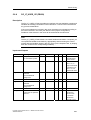
6.10
6.10.1
6.10.2
viii
6-1
Installation.................................................................................................... 6-1
Guide: Installation........................................................................................ 6-1
Introduction .................................................................................................. 6-2
Guide: Introduction ...................................................................................... 6-2
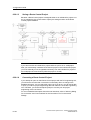
Guide: Route Control, Overview.................................................................. 6-3
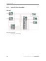
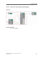
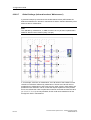
Guide: Route Control, General (Architecture) ............................................. 6-4
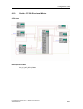
Guide: Route Control, General (Project Engineering)................................. 6-5
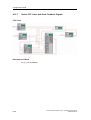
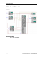
Guide: Route Control, General (Server, Client)........................................... 6-6
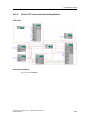
Guide: Route Control, General (AS)............................................................ 6-7
Guide: Route Control, General (User Program) .......................................... 6-8
Guide: Route Control Configuration ............................................................ 6-9
Guide: Predefined Element Types .............................................................. 6-9
Guide: Printing Out a Project..................................................................... 6-10
Guide: Setting Up a New Project............................................................... 6-11
Configuring with SIMATIC Manager.......................................................... 6-13
CFC - Overview ......................................................................................... 6-13
Route Control Blocks (Run Sequence) ..................................................... 6-14
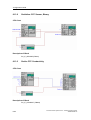
Hardware Configuration (HW Config)........................................................ 6-14
Component Configurator ........................................................................... 6-16
S7 Project .................................................................................................. 6-17
Guide: Configuring the Automation Systems ............................................ 6-17
Guide: Configuring AS-AS and AS-OS Connection .................................. 6-18
Guide: CFC Charts .................................................................................... 6-20
Guide: Route Control, SFC Type............................................................... 6-21
Route Control Wizard ................................................................................ 6-22
Guide: Route Control Wizard..................................................................... 6-22
Guide: Exporting Routes ........................................................................... 6-24
Guide: Exporting from an S7 Project to a Route Control Project .............. 6-27
Guide: Exporting a Connection Configuration (NetPro) ............................ 6-28
Configuring the Route Control Project....................................................... 6-30
Guide: Route Control Project..................................................................... 6-30
Guide: Configuring the RC Server (Redundant)........................................ 6-32
Guide: Configuring the RC Server (Standalone) ....................................... 6-33
Guide: 'Offline' Route Search .................................................................... 6-34
Guide: Cross-Reference List of Elements ................................................. 6-36
Guide CSV Interface.................................................................................. 6-37
Guide: CSV Interface................................................................................. 6-37
CSV Interface (Export Log) ....................................................................... 6-38
CSV Interface (Import Log)........................................................................ 6-39
Route Control SFC .................................................................................... 6-40
SFC: Overview........................................................................................... 6-40
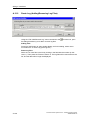
Guide: Relationship between SFC and Route,
Including Operator Dialogs ........................................................................ 6-41
SFC: Schematic......................................................................................... 6-42
SFC: Start Conditions for Holding ............................................................. 6-43
SFC: Mode Levels ..................................................................................... 6-44
SFC: S88 Status........................................................................................ 6-44
SFC: SFC Editor ........................................................................................ 6-45
SFC: Complete Interconnection ................................................................ 6-45
Route Control CFC Examples ................................................................... 6-46
Guide: CFC Overview, Examples.............................................................. 6-46
Configuration ............................................................................................. 6-48
Guide: CFC Configuring One Automation System .................................... 6-48
Guide: CFC Configuring One of Multiple Automation Systems................. 6-49
Process Control System PCS 7 - SIMATIC Route Control
A5E00343836-02
Contents
6.11
6.11.1
6.11.2
6.11.3
6.12
6.12.1
6.12.2
6.12.3
6.12.4
6.12.5
6.12.6
6.12.7
6.12.8
6.12.9
6.12.10
6.12.11
6.13
6.13.1
6.13.2
6.13.3
6.14
6.14.1
6.15
6.15.1
6.16
6.16.1
6.16.2
6.17
6.17.1
6.17.2
6.17.3
6.17.4
6.17.5
6.18
6.18.1
6.19
6.19.1
6.19.2
6.19.3
6.20
6.20.1
6.20.1.1
6.20.1.2
6.20.1.3
6.20.1.4
6.20.1.5
6.20.1.6
6.21
6.21.1
6.22
6.22.1
6.23
6.23.1
Route ......................................................................................................... 6-50
Guide: CFC Route ..................................................................................... 6-50
Guide: CFC Encoder ................................................................................. 6-51
Guide: CFC Decoder ................................................................................. 6-51
Control Elements ....................................................................................... 6-52
Guide: CFC Control Element..................................................................... 6-52
Guide: CFC Dual-State Motor ................................................................... 6-53
Guide: CFC Dual-State Motor with No Feedback ..................................... 6-54
Guide: CFC Motor with Interlocking Module.............................................. 6-55
Guide: CFC Dual-Speed Motor ................................................................. 6-56
Guide: CFC Bi-Directional Motor ............................................................... 6-57
Guide: CFC Valve with Dual Feedback Signals ........................................ 6-58
Guide: CFC Valve with Interlocking Module.............................................. 6-59
Guide: CFC Valve with Feedback ............................................................. 6-60
Guide: CFC Valve with No Feedback Signal............................................. 6-61
Guide: CFC Motor Valve ........................................................................... 6-62
Sensor Elements ....................................................................................... 6-63
Guide: CFC Sensor Element ..................................................................... 6-63
Guideline: CFC Sensor, Binary ................................................................. 6-64
Guide: CFC Conductivity ........................................................................... 6-64
Parameter Element.................................................................................... 6-65
Guide: CFC Parameter Element................................................................ 6-65
Linking Element ......................................................................................... 6-66
Guide: CFC Linking Element ..................................................................... 6-66
Route Control Client .................................................................................. 6-67
Guide: Route Control Faceplate for WinCC .............................................. 6-67
Guide: Operator Control & Monitoring....................................................... 6-68
NetPro Examples....................................................................................... 6-69
Guide: Configuring NetPro, Overview ....................................................... 6-69
Guide: Configuring NetPro with One AS ................................................... 6-70
Guide: Configuring NetPro: AS 1 of Two ASs ........................................... 6-70
Guide: Configuring NetPro: AS 2 of Two ASs ........................................... 6-71
H-Machines................................................................................................ 6-72
Route Control AS....................................................................................... 6-73
Guide: Route Control Automation System ................................................ 6-73
Route Control Server................................................................................. 6-74
Guide: Route Control Server ..................................................................... 6-74
Guide: Startup of the Route Control System ............................................. 6-75
Guide: Material Sequences during Runtime.............................................. 6-76
Route Control Special Topics .................................................................... 6-77
Remote Elements ...................................................................................... 6-77
Remote Elements, CFC Example ............................................................. 6-77
Guide: CFC Remote Elements .................................................................. 6-80
Remote Elements (NetPro Local AS)........................................................ 6-83
Remote Elements (NetPro Peer AS)......................................................... 6-83
Remote Elements (CFC Chart Local AS).................................................. 6-84
Remote Elements (CFC Chart Peer AS)................................................... 6-85
Dynamic ID Assignment ............................................................................ 6-86
Guide: Dynamic ID Assignment................................................................. 6-86
Overlapping Routes................................................................................... 6-87
Guide: Overlapping Routes ....................................................................... 6-87
Setpoints during Runtime .......................................................................... 6-88
Guide: Setpoints during Runtime (External Parameter Elements)............ 6-88
Process Control System PCS 7 - SIMATIC Route Control
A5E00343836-02
ix
Contents
6.24
6.24.1
6.24.2
6.24.3
6.25
6.25.1
6.25.2
6.25.3
6.25.4
6.25.5
6.25.6
6.25.7
6.25.8
6.25.9
6.25.10
6.25.11
6.25.12
6.25.13
6.26
6.26.1
6.26.1.1
6.26.1.2
6.26.1.3
6.26.1.4
6.26.1.5
6.26.1.6
6.26.1.7
6.26.1.8
6.26.2
6.26.2.1
6.26.2.2
6.26.2.3
6.26.2.4
6.26.2.5
6.26.2.6
6.26.2.7
6.26.2.8
6.26.2.9
6.26.2.10
6.26.2.11
6.26.2.12
6.26.2.13
6.26.3
6.26.3.1
6.26.3.2
6.26.3.3
6.26.3.4
6.26.3.5
6.26.3.6
6.26.3.7
6.26.3.8
6.26.3.9
6.26.3.10
6.26.3.11
6.26.3.12
6.26.3.13
6.26.3.14
x
Material ...................................................................................................... 6-90
Guide: Project Engineering of Material Sequences .................................. 6-90
Project Engineering of Materials................................................................ 6-90
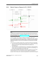
Material: Sequence Diagram for RC_IF_ROUTE...................................... 6-91
Configuring SIMATIC Manager ................................................................. 6-92
Overview.................................................................................................... 6-92
Downloading Blocks to the AS .................................................................. 6-92
CFC - Modifying Block Ranges ................................................................. 6-93
CFC - Project Engineering Routes ............................................................ 6-94
CFC - Project Engineering of Elements .................................................... 6-94
NetPro - Project Engineering of Cross-Coupling....................................... 6-94
Communication with H-Machines .............................................................. 6-95
Route Control Applications (HW Config) ................................................... 6-95
Route Control Wizard ................................................................................ 6-96
Import from an S7 Project.......................................................................... 6-96
Project Engineering of the Route Control Server ...................................... 6-98
Project Engineering of User-Defined Element Types................................ 6-99
Transfer to Route Control Project Engineering ....................................... 6-100
Configuring RC Configuration Tool ......................................................... 6-101
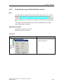
Getting Started ........................................................................................ 6-101
Starting the RC Engineering Tool............................................................ 6-101
Engineering Tool Menu ........................................................................... 6-101
Saving a Route Control Project ............................................................... 6-104
Converting a Route Control Project......................................................... 6-104
Creating a New RC Project ..................................................................... 6-105
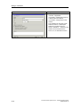
Main View of the RC Engineering Tool ................................................... 6-105
Transferring Data from an S7 Project...................................................... 6-105
Server and Redundancy Scenarios......................................................... 6-105
Global Project Settings ............................................................................ 6-106
Global Settings ........................................................................................ 6-106
Global Settings – General ....................................................................... 6-107
Global Settings – Material ....................................................................... 6-109
Runtime Parameters (External Material Configuration) .......................... 6-110
Global Settings - Rules for the Route Algorithm...................................... 6-111
Global Settings - Monitoring (Redundancy) ............................................ 6-112
Global Settings (Information about 'Maintenance').................................. 6-114
Global Settings (Monitoring of Servers and AS)...................................... 6-116
Configuration of a Route Control Server ................................................. 6-116
Configuration of a Route Control Server Pair (Redundancy)................... 6-116
Route Log (Configuration)........................................................................ 6-117
Route Log (Directory Sharing) ................................................................. 6-117
Route Log (Loading Settings on the Server)............................................ 6-118
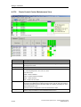
Objects..................................................................................................... 6-119
Plant Hierarchy ........................................................................................ 6-119
Locations ................................................................................................. 6-119
Locations (Properties Dialog) .................................................................. 6-120
Locations (Examples) .............................................................................. 6-121
Unit Location Type................................................................................... 6-123
Transport Set Name ................................................................................ 6-123
Mode Tables ............................................................................................ 6-123
Mode Levels ............................................................................................ 6-124
Automatic Generation of Elements.......................................................... 6-125
Deleting Elements .................................................................................... 6-125
Elements .................................................................................................. 6-125
Element Subtypes .................................................................................... 6-126
Predefined Routes.................................................................................... 6-126
Interconnecting an Element ..................................................................... 6-126
Process Control System PCS 7 - SIMATIC Route Control
A5E00343836-02
Contents
6.26.3.15
6.26.3.16
6.26.4
6.26.4.1
6.26.4.2
6.26.4.3
6.26.4.4
6.26.5
6.26.5.1
6.26.5.2
6.26.5.3
6.26.5.4
6.26.5.5
6.26.6
6.26.6.1
6.26.7
6.26.7.1
6.26.7.2
6.26.8
6.26.8.1
6.27
6.27.1
6.28
6.28.1
6.29
6.29.1
6.29.2
6.29.3
6.29.3.1
6.29.3.2
6.29.3.3
6.29.3.4
6.29.3.5
6.29.3.6
6.29.3.7
7
Partial Routes........................................................................................... 6-127
Routes ...................................................................................................... 6-128
Materials .................................................................................................. 6-129
Material (Overview) ................................................................................. 6-129
Project Engineering of Materials.............................................................. 6-129
Project Engineering of Material Groups .................................................. 6-129
Project Engineering of Permitted Successor Materials ........................... 6-129
Exporting into the Server ......................................................................... 6-130
Loading the Route Control Server ........................................................... 6-130
Case 1: Server 1 Can Be Loaded but Not Server 2 ................................ 6-131
Case 2: Server 2 Can Be Loaded but Not Server 1 ................................ 6-131
Case 3: Both Servers Can Be Loaded .................................................... 6-131
Case 4: Neither Server Can Be Loaded.................................................. 6-131
Checking Data Consistency .................................................................... 6-132
Route Control Engineering: Checking Data Consistency........................ 6-132
Mode Levels ............................................................................................ 6-133
Project Engineering of Mode Tables ....................................................... 6-133
Project Engineering of Mode Levels........................................................ 6-135
Partial Route Network.............................................................................. 6-137
Project Engineering of Partial Routes ..................................................... 6-137
Project Engineering of RC Faceplate ...................................................... 6-139
WinCC Faceplate .................................................................................... 6-139
Project Engineering of RC Center ........................................................... 6-140
Configuration of the Route Control Center .............................................. 6-140
Project Engineering of RC Server ........................................................... 6-141
Configuration of Route Control Server .................................................... 6-141
Loading the Route Control Server (Redundancy) ................................... 6-141
External Material Interface....................................................................... 6-142
Material Interface..................................................................................... 6-142
Material Interface (Architecture) .............................................................. 6-143
Material Interface (Transfer Files) ........................................................... 6-144
Material Interface (Material Master Data)................................................ 6-144
Material Interface (Successor Relationships).......................................... 6-145
Material Interface (Example) ................................................................... 6-146
Material Interface (Test) .......................................................................... 6-147
OS Operator Control and Monitoring
7.1
7.2
7.3
7.3.1
7.3.2
7.3.3
7.4
7.4.1
7.4.2
7.5
7.5.1
7.6
7.6.1
7.6.2
7.6.3
7.6.4
7.7
7.7.1
7.7.2
7-1
Overview...................................................................................................... 7-1
Using the WinCC Keyset to Call the RC Center.......................................... 7-2
Server .......................................................................................................... 7-3
RC Server: Overview................................................................................... 7-3
RC Server: Startup Sequence ..................................................................... 7-3
RC Server: Status........................................................................................ 7-4
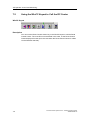
RC Block Icon for a Route ........................................................................... 7-6
RC Block Icon for a Route ........................................................................... 7-6
RC Block Icon (Display Elements)............................................................... 7-7
RC Faceplate (Client) .................................................................................. 7-8
RC Block Icon and Faceplate ...................................................................... 7-8
RC Center (Client) ....................................................................................... 7-9
RC Center (Client) ....................................................................................... 7-9
RC Server: Redundancy Failover................................................................ 7-9
RC Support for Maintenance Work ............................................................. 7-9
AS in Maintenance .................................................................................... 7-10
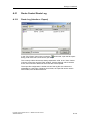
RC Routes Log .......................................................................................... 7-11
Route Log .................................................................................................. 7-11
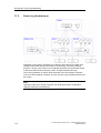
Route Log (Architecture) ........................................................................... 7-12
Process Control System PCS 7 - SIMATIC Route Control
A5E00343836-02
xi
Contents
7.8
7.8.1
7.9
7.9.1
7.9.2
7.9.3
7.9.3.1
7.9.3.2
7.9.3.3
7.9.3.4
7.9.3.5
A
Dialogs / Interfaces
A.1
A.2
A.2.1
A.2.2
A.2.3
A.2.4
A.2.5
A.2.6
A.2.7
A.2.8
A.3
A.3.1
A.3.2
A.4
A.4.1
A.4.2
A.5
A.5.1
A.5.2
A.5.3
A.5.4
A.5.5
A.5.6
A.5.7
A.6
A.6.1
A.6.2
A.6.3
A.6.4
A.7
A.7.1
A.7.2
A.7.3
A.7.4
A.8
A.8.1
A.8.2
A.8.3
A.8.4
A.9
A.9.1
A.9.1.1
A.9.2
xii
Server ........................................................................................................ 7-13
Route Log (Log File).................................................................................. 7-13
Client.......................................................................................................... 7-14
Route Log (Interface)................................................................................. 7-14
Route Log (Interface - Rights) ................................................................... 7-15
Route Log (Interface - Menu) .................................................................... 7-15
Route Log (Interface - List of Log Files) .................................................... 7-16
Route Log (Interface - Filter Functions)..................................................... 7-16
Route Log (Interface - Table of Log Data)................................................. 7-16
Route Log (Interface - Columns) ............................................................... 7-17
Route Log (Interface - Status Bar) ............................................................ 7-17
A-1
Dialogs.........................................................................................................A-1
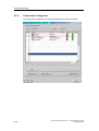
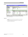
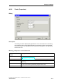
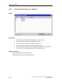
Route Control Configuration interface .........................................................A-4
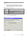
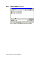
Logon Dialog................................................................................................A-4
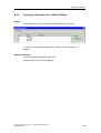
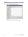
Converting a Route Control Project.............................................................A-5
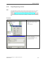
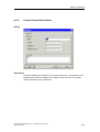
Route Control Project Engineering Interface...............................................A-7
Runtime Parameters (Properties)................................................................A-7
Project Settings (Properties)........................................................................A-8
Server (Properties) ......................................................................................A-9
Connections (Properties)...........................................................................A-10
Route (Properties) .....................................................................................A-11
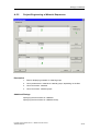
Technological Hierarchy (Process Cell) ....................................................A-12
Project Engineering of a Process Cell.......................................................A-12
Project Engineering of a Unit.....................................................................A-13
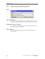
Locations ...................................................................................................A-14
Project Engineering of Plant-Neutral Locations.........................................A-14
Project Engineering of Plant-Related Locations........................................A-15
Material ......................................................................................................A-17
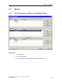
Project Engineering of Materials and Material Groups..............................A-17
Adding, Changing, and Deleting a Material...............................................A-18
Adding, Changing, and Deleting a Material Group....................................A-19
Assigning Materials to a Material Group ...................................................A-20
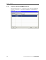
Project Engineering of Material Sequences ..............................................A-21
Specifying Successors for a Material ........................................................A-22
Specifying Successors for a Material Group .............................................A-23
Elements....................................................................................................A-24
Control Element (Properties) .....................................................................A-24
Control Element (Activation)......................................................................A-25
Control Element (Cross-Reference List) ...................................................A-27
Route Control Element (Properties) ..........................................................A-29
Sensor Elements .......................................................................................A-30
Sensor Element (Control) ..........................................................................A-30
Sensor Element (Properties) .....................................................................A-31
Sensor Element (Cross-Reference List)....................................................A-31
Route Sensor Element (Properties) ..........................................................A-32
Parameter Elements..................................................................................A-33
Parameter Element (Activation).................................................................A-33
Parameter Element (Properties)................................................................A-34
Parameter Element (Cross-Reference List) ..............................................A-35
Route Parameter Element (Properties) .....................................................A-35
Linking Elements .......................................................................................A-37
Linking Element (Properties) .....................................................................A-37
Linking Element (Cross-Reference List)....................................................A-37
Route Linking Element (Properties) ..........................................................A-38
Process Control System PCS 7 - SIMATIC Route Control
A5E00343836-02
Contents
A.10
A.10.1
A.11
A.11.1
A.12
A.12.1
A.13
A.13.1
A.13.2
A.14
A.14.1
A.15
A.15.1
A.16
A.16.1
A.17
A.17.1
A.17.2
A.17.3
A.17.4
A.17.5
A.17.6
A.17.7
A.17.8
A.17.9
A.17.10
A.18
A.18.1
A.18.2
A.18.3
A.19
A.19.1
A.19.2
A.19.3
A.19.4
A.20
A.20.1
A.20.2
A.20.3
A.20.4
A.21
A.21.1
A.22
A.22.1
A.22.2
A.22.3
A.22.4
A.22.5
A.22.6
A.23
A.23.1
A.23.2
A.23.3
A.23.4
A.23.5
A.23.6
Automation System ...................................................................................A-39
Automation System (Properties)................................................................A-39
Function ID and Level................................................................................A-40
Function ID (Properties) ............................................................................A-40
Consistency Check....................................................................................A-41
Consistency Check (Result) ......................................................................A-42
Mode Catalog ............................................................................................A-43
Mode Table (Properties)............................................................................A-43
Mode Level (Properties) ............................................................................A-44
Partial Route ..............................................................................................A-45
Partial Route (Properties) ..........................................................................A-45
Unit Location Type.....................................................................................A-47
Unit Location Type (Properties).................................................................A-47
Loading Server ..........................................................................................A-48
Loading the Route Control Server .............................................................A-48
Route Control Wizard (Export) ..................................................................A-49
Route Control Wizard: Actions ..................................................................A-49
Route Control Wizard: Selecting Actions ..................................................A-50
Route Control Wizard: Selecting a WinCC Message Server ....................A-51
Route Control Wizard: AS-OS Connection (MAC Address)......................A-52
Route Control Wizard: AS-OS Connection (TCP/IP Address) ..................A-52
Route Control Wizard: Selecting Objects To Be Exported........................A-53
Route Control Wizard: Summary...............................................................A-54
Route Control Wizard: Adapting IDs .........................................................A-55
Route Control Wizard: Result ....................................................................A-57
Route Control Wizard (Export Log) ...........................................................A-58
Network Combinations ..............................................................................A-59
Route Control Wizard: Network Constellations .........................................A-59
Route Control Wizard: Network Constellations (Examples)......................A-60
Route Control Wizard: Network Constellations (Note) ..............................A-61
Server Combinations .................................................................................A-62
Route Control Server with and without WinCC OS ...................................A-62
Route Control Configurations ....................................................................A-62
Route Control Configurations (non-redundant) .........................................A-63
Route Control Configuration (redundant) ..................................................A-64
Route Control Wizard (Import)...................................................................A-66
Route Control Wizard: How Synchronization Works .................................A-66
Route Control Wizard: Import ....................................................................A-67
Route Control Wizard (Import Log)............................................................A-70
Deleting Used Elements ............................................................................A-71
Route Control Block Icon...........................................................................A-72
RC Block Icon Interconnection ..................................................................A-72
Route Control WinCC Wizard....................................................................A-73
Route Control: WinCC Wizard (Overview) ................................................A-73
Route Control: WinCC Wizard (Start)........................................................A-74
Route Control: WinCC Wizard (Welcome Dialog) .....................................A-75
Route Control: WinCC Wizard (Instance Selection)..................................A-76
Route Control: WinCC Wizard (SFC) ........................................................A-78
Route Control: WinCC Wizard (Summary)................................................A-79
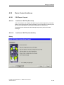
Route Control Faceplate............................................................................A-80
RC Route Faceplate ..................................................................................A-80
RC Faceplate/Status of Route...................................................................A-81
RC Faceplate (Display and Operator Control Elements) - 1/4 ..................A-82
RC Faceplate (Display and Operator Control Elements) - 2/4 ..................A-83
RC Faceplate (Display and Operator Control Elements) - 4/4 ..................A-84
RC Faceplate (Display and Operator Control Elements) - 3/4 ..................A-85
Process Control System PCS 7 - SIMATIC Route Control
A5E00343836-02
xiii
Contents
A.24
A.24.1
A.24.1.1
A.24.1.2
A.24.1.3
A.24.1.4
A.25
A.25.1
A.25.2
A.25.3
A.25.4
A.25.5
A.25.6
A.26
A.26.1
A.26.2
A.26.3
A.27
A.27.1
A.27.2
A.27.3
A.27.4
A.27.5
A.27.6
A.28
A.28.1
A.28.1.1
A.28.1.2
A.28.1.3
A.28.1.4
A.28.1.5
A.28.1.6
A.28.1.7
A.28.1.8
A.28.1.9
A.28.1.10
A.29
A.29.1
A.30
A.30.1
A.30.2
A.30.3
A.30.4
A.30.5
A.30.6
A.31
A.31.1
A.31.2
A.31.3
A.31.4
A.32
A.32.1
A.32.2
A.32.2.1
A.32.2.2
A.32.2.3
xiv
Route Control Center.................................................................................A-86
Start und Logon .........................................................................................A-86
Route Control Center: Logon.....................................................................A-86
Route Control Center: Selection of Route Control Server.........................A-86
Route Control Center: Adding a Server.....................................................A-88
Route Control Center: Find Server ............................................................A-89
Menu and Statusbar / Toolbar ...................................................................A-90
Route Control Center: Menu......................................................................A-90
Route Control Center: General Operator Control Elements......................A-92
Route Control Center: Server Status.........................................................A-93
Updating the Route Control Server ...........................................................A-94
Route Control Center: Options/Settings ....................................................A-95
Route Control Center: Status Bar..............................................................A-95
Route Properties........................................................................................A-96
Route Control Center: Route Properties ...................................................A-96
Route Control Center: Locations ...............................................................A-97
Route Control Center: Error during Route Request ..................................A-98
Interface.....................................................................................................A-99
Route Control Center: Route Overview.....................................................A-99
Route Control Center: Elements..............................................................A-100
Route Control Center: Sorting .................................................................A-101
Route Control Center: Activation Keys....................................................A-102
Route Control Center: Modes..................................................................A-103
Route Control Center: Maintenance View ...............................................A-104
Route Control Interfaces..........................................................................A-105
CSV Export / Import.................................................................................A-105
Interfaces: CSV File (Overview) ..............................................................A-105
Interfaces: CSV File (Introduction) ..........................................................A-105
Interfaces: CSV File (Global Settings).....................................................A-106
Interfaces: CSV File (Object Selection)...................................................A-108
Interfaces: CSV File (Summary)..............................................................A-109
Interfaces: CSV File (Progress Dialog) ...................................................A-110
Interfaces: CSV File (Result) ...................................................................A-111
Interfaces: CSV File (Log File) ................................................................A-112
Interfaces: CSV File (Structure)...............................................................A-113
Interfaces: CSV File (Error Messages) ....................................................A-118
S7 Project Data Import ............................................................................A-119
Interfaces: Importing S7 Project Data .....................................................A-119
Route Control Server...............................................................................A-119
RC Server: User Interface Dialog ............................................................A-119
RC Server: Switching Languages ...........................................................A-121
RC Server: Expanded Diagnostics (AS List) ...........................................A-121
RC Server: Expanded Diagnostics (Route List) ......................................A-123
RC Server: Expanded Diagnostics (OS-AS Connections) ......................A-125
RC Server: Expanded Diagnostics (Clients/RCC)...................................A-126
Route Control Route Log.........................................................................A-127
Route Log (Interface - Export) .................................................................A-127
Route Log (Adding/Removing Log Files) ................................................A-128
Route Log (Adding a Log File).................................................................A-129
Route Log (Selection of Visible Columns)...............................................A-130
Messages ................................................................................................A-131
Overview of RC Messages ......................................................................A-131
OS Messages ..........................................................................................A-132
Route Control Messages, OS..................................................................A-132
Route Control Messages, OS (System, Server)......................................A-132
Route Control Messages, OS (Route, Server) ........................................A-134
Process Control System PCS 7 - SIMATIC Route Control
A5E00343836-02
Contents
A.32.3
A.32.3.1
A.32.3.2
A.32.3.3
A.32.3.4
A.32.3.5
A.32.3.6
A.32.4
A.32.4.1
A.33
A.33.1
A.33.2
A.33.3
A.33.4
A.33.5
A.33.6
A.33.7
A.33.8
A.33.9
A.33.10
A.34
A.34.1
A.35
A.35.1
A.35.2
A.35.3
A.35.4
A.35.5
A.35.6
A.35.7
A.36
A.36.1
A.36.2
A.36.3
B
AS Messages...........................................................................................A-136
Route Control Messages, AS ..................................................................A-136
Route Control Messages, AS (System, FB850) ......................................A-136
Route Control Messages, AS (Route, FB800) ........................................A-138
Route Control Messages, AS
(Control Elements, FB822, 823, 824, 825)..............................................A-143
Route Control Messages, AS (Sensor Elements, FB845, 846) ..............A-144
Route Control Messages, AS (Remote Elements, FB831, 833) .............A-145
Operator Messages .................................................................................A-146
Route Control Messages (Operator Messages)......................................A-146
Value Ranges ..........................................................................................A-147
Overview of Valid Value Ranges .............................................................A-147
Valid Route IDs........................................................................................A-148
Valid Function Identification.....................................................................A-149
Maximum Valid Route Request Time......................................................A-149
Maximum Valid Material Acceptance Time .............................................A-149
Valid Material IDs ....................................................................................A-150
Value Range for IDs of CEs, SEs, LEs, and PEs....................................A-150
Value Range for SNDRCVDB for Remote Elements ..............................A-151
Value Range for AS Numbers .................................................................A-151
External Parameter Elements (Index) .....................................................A-152
Quantity Framework ................................................................................A-153
Quantity Framework for Route Control....................................................A-153
Diagnostics / Log .....................................................................................A-155
Diagnostic Trace......................................................................................A-155
Diagnostics Overview ..............................................................................A-155
Diagnostics for Engineering.....................................................................A-155
Diagnostics for Operator Control and Monitoring ....................................A-156
Diagnostics for Export and Import of Project Engineering Data..............A-158
Diagnostics for Cross-Coupling ...............................................................A-158
Diagnostics for RC Server .......................................................................A-159
FAQ .........................................................................................................A-159
Subsequent Modification of AS-ID ..........................................................A-159
AS Load Due to Route Execution............................................................A-160
Network Security .....................................................................................A-161
Abbreviations
B.1
B.1.1
B.1.2
B-1
General ........................................................................................................B-1
S88 Terms ...................................................................................................B-1
Abbreviations ...............................................................................................B-2
Glossary
Index
Process Control System PCS 7 - SIMATIC Route Control
A5E00343836-02
Glossary-1
Index-1
xv
Contents
xvi
Process Control System PCS 7 - SIMATIC Route Control
A5E00343836-02
1
What's New
1.1
Welcome
Welcome to SIMATIC Route Control.
Process Control System PCS 7 - SIMATIC Route Control
A5E00343836-02
1-1
What's New
1.2
What's New in SIMATIC Route Control V6.0?
In this section, you will find information about the new and expanded functions of
SIMATIC Route Control V6.0 as compared to the previous versions:
•
Route Control V5 based on BRAUMAT V5
•
Route Control V5 based on PCS 7 V5
•
Windows 2000 Capability
General
Like PCS 7, SIMATIC Route Control V6.0 can run on the Windows 2000
operating system.
•
Integration in PCS 7
User Interfaces
A major component of the Route Control V6.0 product is its integration in the
PCS 7 environment. In many areas, the user interfaces (dialogs, icons, etc.)
have been revised, simpler procedures for working with the tools have been
introduced, and a wizard and WinCC faceplate have been added. The Route
Control Wizard also includes a plausibility check of the configured element and
route blocks to detect errors early and ensure data consistency between the
project and the Route Control project.
AS-OS Connection (Route Control AS and Server)
Connection between the automation systems and the Route Control server is
carried out by means of BSEND services (in V5, this was accomplished using
alarm services).
Messages
Blocks in the Route Control library now use standard alarm services (ALARM
blocks) and communication routes to a WinCC message server. (In V5,
messages could only be sent via the Route Control server, and there were no
Route Control AS messages sent directly to WinCC.)
To avoid dependence on BRAUMAT / SISTAR library blocks (V5), the required
blocks have been integrated in the Route Control library.
Elimination of Major Sources of Error
In Route Control V6.0, the data areas in the automation systems have been
separated and revised, thus eliminating the problem of extended data blocks
that occurred in V5. As a result, route data (now located in the instance data
block of RC_IF_ROUTE, see below) are separated from the actual element list
(still DB101 to DB400).
To reduce the burden on the OB1 cycle, route blocks can now also be called in
other organization blocks.
1-2
Process Control System PCS 7 - SIMATIC Route Control
A5E00343836-02
What's New
•
Basic Package - Incremental Expansion of Number of Material Transports
The basic package for SIMATIC Route Control V6.0 supports material
transports, from project engineering to the runtime system, to operator control
and monitoring of routes and route elements, including process messages.
The basic package has a limit of 30 routes (= 30 simultaneous material
transports, maximum). An upgrade package provides an incremental
expansion to 100 or 300 material transports.
•
Option Packages
The functionality of SIMATIC Route Control V6.0 cannot yet be expanded in
Phase 1 (V6.0) by adding option packages to the basic package. Option
packages (H-Option and S7-317) will not be available until Route Control V6.1.
For additional information, see the Readme file for SIMATIC Route Control
V6.0.
•
Redundancy
Route Control provides the option of a redundant configuration for the Route
Control server that processes route requests, thus ensuring permanent
availability (see "Fault-Tolerant Route Control").
•
Integration in PCS 7 OS
Route Control V6.0 provides improved integration in the PCS 7 OS (client) with
a faceplate, a WinCC faceplate, and a cross-selection between WinCC pictures
and the Route Control Center (displaying information about a route).
Project Engineering in the Engineering System
Several important additions have been made for project engineering of the
routing system, making it easier to enter and import existing data from an S7
project in a Route Control project.
A portion of the project engineering takes place in SIMATIC Manager and
associated applications:
-
CFC: project engineering of routes
-
CFC: project engineering of elements
-
CFC: configuration of a Route Control automation system
-
NetPro: project engineering of AS-AS connections
-
NetPro: project engineering of AS-OS connections
The Route Control Wizard provides assistance to facilitate all of these aspects
of project engineering.
•
Route Control Server and Route Control Clients
Because Phase 1 does not yet have its own Route Control object manager
(OM) in SIMATIC Manager, settings for the Route Control server are made in
the Route Control Wizard, imported in the Route Control project engineering,
and then loaded from the RC project engineering onto the server computers.
Process Control System PCS 7 - SIMATIC Route Control
A5E00343836-02
1-3
What's New
•
S7 Standalone and Multiprojects
SIMATIC Route Control V6.0 supports both S7 standalone and S7
multiprojects of SIMATIC Manager. Each standalone or multiproject can have
no more than one Route Control project. If various systems are implemented
using multiple multiprojects, then several Route Control projects must also be
used. The maximum scope of a Route Control project is the multiproject.
•
Type-Based Engineering (Sample SFC for Route Control)
Route Control provides a sample SFC (SFC Typical) for the routing system,
which includes S88 status tabs with sample programming. This SFC can be
copied by the user and modified as required. The SFC provides status based
on S88. The following steps are preconfigured:
•
-
Transfer relevant parameters (source and destination locations, function
ID, material, etc.)
-
Request a route
-
Control a route (mode levels)
-
Deactivate a route
Interface to Processing Programs
The interface between SIMATIC Route Control V6.0 and the actual processing
in the automation system consists of:
•
-
SFC types created using SFC standard tools in PCS 7 V6.0 and higher
-
Route Control interface blocks for:
-
Elements and routes
-
AS-AS cross-coupling within a Route Control project
-
AS-AS cross-coupling beyond several Route Control projects
-
Diagnostics
-
Use of the preconfigured sample SFC
Plant Hierarchy in the Plant View
The plant hierarchy in SIMATIC Manager allows you to display your project
with an appropriate structure. The plant view of the Route Control engineering
system can include up to two levels of the plant hierarchy (process cell and
unit) in accordance with S88.01. These two levels are recognized by the
BATCH attributes in the hierarchy container.
To improve the structure, (bi-level) neutral containers can also be added to the
plant hierarchy in Route Control.
1-4
Process Control System PCS 7 - SIMATIC Route Control
A5E00343836-02
What's New
•
Fault-Tolerant Route Control
Route Control servers can have a redundant configuration to increase
availability (fault tolerance) and enable software updates during operation. A
master/standby failover takes place between the two Route Control servers if
redundant operation is required.
Redundancy is achieved with two Route Control servers in a redundant
configuration, whereby the servers do not require local data storage. To enable
the Route Control client applications (Route Control Center) to access the
current database of the Route Control server, the two local databases are
synchronized with respect to the project engineering. If one Route Control
server fails, the other server again reads in the project engineering database
and initiates a general request. This general request provides the new master
server with the current status of the elements and routes in the automation
systems. This strategy prevents the need for continuous synchronization of the
server data and persistent data on a hard disk. Data must only be
synchronized when a Route Control server is initially loaded from the Route
Control project engineering application (see "Loading the Server"). However,
this process is transparent to the user.
•
Route Control Interface Blocks
SIMATIC Route Control V6.0 takes advantage of the new functionality of SFC
types in the engineering system. Alternatively, SIMATIC Route Control V6.0
still provides special interface blocks with a new technical design as
communication interfaces to the processing programs in the automation
system:
•
Faceplates
A Route Control block icon and control dialog (faceplate) for the
RC_IF_ROUTE block is available for operation on the PCS 7 OS.
•
RC_IF_ROUTE
This is the central block for route activation (previously: ROUTE_CM block).
•
RC_IF_CFG
This block is used centrally one time for each automation system. Parameters
for the automation system number and the communication ID for the crosscoupling configuration are assigned in this block. The IDs can be assigned by
the Route Control Wizard. This makes it easier for you to configure the crosscoupling entries.
•
Route Control Wizard
A wizard in the context of SIMATIC Manager helps the user configure the
cross-coupling communication (communication ID). The wizard can also be
used to export the portion of configured data relevant for Route Control and
import it in the Route Control project engineering:
-
Plant hierarchy
-
Automation systems
-
AS-AS and AS-OS connection information
-
Elements
-
Route properties (route ID and fixed/dynamic specification)
Additionally, the Route Control Wizard is used to specify the relevant message
server (WinCC message OS) for Route Control and to check the element and
route IDs for consistency and plausibility.
Process Control System PCS 7 - SIMATIC Route Control
A5E00343836-02
1-5
What's New
Route Control Runtime System
•
Working in the WinCC Faceplate
The actual faceplate can be opened by means of a block icon that displays the
most important statuses of a route. This block icon shows the status of the
route in various views, enables operator control of the route, and displays the
messages currently pending for the route.
The Route Control operator prompts are displayed in the group display of
PCS 7 OS.
•
Working in the Route Control Center (RCC)
The RCC provides a highly detailed display of the route, route status, elements
and element status, and enables control operations beyond the scope of the
Route Control WinCC faceplate.
•
Authorization Management
SIMATIC Route Control V6.0 supports the SIMATIC Logon central user
management of PCS 7. In Phase 1 (V6.0), five user groups with specific names
must be created in Windows. Due to a redesign of the SIMATIC Logon
component itself, Route Control will be integrated and administered in the
Logon Admintool starting with Route Control V6.1. From a current perspective,
it will then be possible to freely select the names of the user groups.
Miscellaneous Changes
•
On and Off Delay Times for Elements
Starting with Route Control Version 6, the On and Off delay times for elements
relate to the mode level and will be valid across automation systems. These
times are absolute and are no longer relative to the preceding element, as was
the case in Version 5.
When project engineering data are migrated from Version 5 to Version 6, the
conversion tool automatically converts the element times. However, because
these times are now absolute, the maximum time has been limited to 255
seconds.
•
Element Sorting
The sort number for elements in a partial route has been eliminated from the
engineering tool because it was irrelevant with respect to the order in which
elements are switched on or off. Because Route Control V6.0 is currently
designed for transport of liquids only (and materials that can be transported
according to this concept), the sort number has been removed. This sort
number will become relevant when solid material variants are introduced
because interlocking of elements is dependent on the element sequence for
these materials.
1-6
Process Control System PCS 7 - SIMATIC Route Control
A5E00343836-02
What's New
1.3
What's New in SIMATIC Route Control V6.0 SP1 ?
Route Control V6.0 Service Pack 1 has the following new functions:
•
External material interface
It is now possible to apply material master data from an external source to the
Route Control server. In addition to the actual materials, the successor
relationships can also be defined.
Material Interface
•
Route Log
The following information is recorded in the route log:
•
Operator input by means of the Route Control Center
•
Status of a route (Start, Stop, Pause, etc., mode activation/deactivation).
•
Startup, operation, and shutdown of the Route Control server
These route logs can be displayed and saved using an application that is provided
with SIMOTION Route Control. This route log interface offers a wide range of
functions for filtering, searching, and evaluating logs.
Route Log
•
User-defined element blocks
In addition to the preset element types (control, parameter, linking, and sensor
elements), users can also define their own element types (CFC), apply them in the
Route Control project engineering, and interconnect them in partial routes.
Example for User-Defined Type
Note
You can access all changes relating to Route Control V6.0 SP1 in this online Help
system by searching for "SP1".
Process Control System PCS 7 - SIMATIC Route Control
A5E00343836-02
1-7
What's New
1.4
What's New in SIMATIC Route Control V6.1?
Integration in the PCS 7 System Setup
Beginning with SIMATIC Route Control V6.1, this product is available to you from
within the system setup for PCS 7. Similar to other add-on packages, you can
select which product you wish to install at the beginning of the system setup and
the system setup will perform the installation automatically without further
prompting, see also Installing Route Control Components
Automation License Manager (ALM)
As of version V6.1, SIMATIC Route Control supports the Automation
License Manager. The license model of Route Control has thereby been enhanced
– see also Authorization (Overview)
Route Control Maintenance Safety
Route Control V6.1 provides support to servicing personnel by enabling them to set
the automation system to "Maintenance" status. New material transports are then
prevented through this automation system - RC Support for Maintenance Work
Operating Systems
SIMATIC Route Control can now run under Windows XP Professional (RC Center,
RC Engineering) or Windows 2003 Server (RC Server) in addition to Windows
2000, see also Hardware and Software
SIMATIC S7 417-H
Route Control V6.1 now also supports SIMATIC S7 H-CPUs. In addition to the
server level, the automation systems can now also be designed and implemented
with fault-tolerance. The Route Control library has been adapted correspondingly
so that both non-H and H-machines are supported. A combination of devices is
also possible. This means a route can be controlled by both H-machines and nonH machines. See also Communication with H-Machines
HW Configuration
You can now use the HW Config application to configure the Route Control server
and get support from the Route Control Wizards when generating the named
communication connections. These connections are also downloaded to the PC
station on the target computer similar to other WinCC or BATCH servers - the
connections are then established by the Route Control server via these configured
connections, see Hardware Configuration (HW Config)
1-8
Process Control System PCS 7 - SIMATIC Route Control
A5E00343836-02
What's New
CPU Firmware
SIMATIC Route Control now also supports CPUs with firmware versions before
V3.1.0. The Route Control Wizard no longer stops with an error message; it only
shows a warning. We still recommend that you use firmware V3.1.0 or later.
SIMATIC logon
SIMATIC Route Control V6.1 is now based on the same version of SIMATIC Logon
as all other PCS7 V6.1 products. The authorization policy has not changed in
comparison to RC V6.0 or V6.0 SP1. See User Roles for Route Control.
Multiprocessor Computers
SIMATIC Route Control can not run on computers with more than one processor.
Security
With SIMATIC Route Control, the share attribute for directories is no longer
available for "everyone". It can only be used by Route Control groups
(RC_ENGINEER, RC_MAINTENANCE, RC_OPERATOR_L1 .. L3). This means
that only users belonging to one of these groups can access the shared directories
from another computer.
Material in the RC Center
Material can not be changed even during an active route (manual mode) in the
Route Control Center. Before RC V6.0 SP1, it was only possible to change the
material when the route was not active. See Route Control Center: Route
Properties.
Route Control messages
In the WinCC alarm server for Route Control messages, Route Control wizards no
longer generate messages based on the route instance for all configured routes;
they only generate messages in general form.
Example: the message "Faulty route %d" is generated instead of "Faulty route 23".
The wildcard (%d) is assigned the number of the corresponding route during
runtime and generates a message.
This means message definitions in a WinCC project (OS) can be created 300%
faster using the Route Control Wizard.
Process Control System PCS 7 - SIMATIC Route Control
A5E00343836-02
1-9
What's New
1.5
What's New in SIMATIC Route Control V6.1 SP1 ?
Note
The tasks involved in migrating V6.1 projects to V6.1 SP1 are described under:
Migration V6.1 to V6.1 SP1
Route Control Applications in the Hardware Configuration (HW Config)
Prior to V6.1, users had to configure a standard application for the Route Control
server in HW Config. The Route Control Wizard asked for this application when
exporting objects to the Route Control Engineering project. As of V6.1 SP1, special
SIMATIC Route Control applications are configure in HW Config. The following
applications are offered for Route Control:
•
RC application
•
RC application (standby)
•
RC application client
An RC application is the preferred station (server master) for Route Control. A
WinCC application and/or Batch application can also run on this station. Following
a switchover, this station becomes the standby station for all applications running
on it (see also Route Control Redundancy).
An RC application (stby) is the substitute station (server standby) for Route
Control. A WinCC application (stby) and/or Batch application (stby) can also run on
this station. Following a switchover, this station becomes the master station for all
applications running on it (see also Route Control Redundancy).
An RC application client represents a station on which a Route Control Center
(client) is installed. The RC application is needed to load the Route Control based
configuration (one or two computer names for the Route Control servers) to the
client station.
See also:
•
Route Control Applications (HW Config)
•
Route Control Configurations
•
Route Control Configurations (non-redundant)
•
Route Control Configurations (redundant)
Downloading the Configuration to a Route Control Client
Once the Route Control server application(s) are configured, this information can
be downloaded to a Route Control client. This configuration with the names of the
Route Control servers replaces the previous selection dialog in the Route Control
Center application. An RC application client should be marked in the SIMATIC
Manager S7 project for downloading the configuration. You then right-click on it
and select the context menu command "Download".
See also:
•
1-10
Route Control Center: Selecting a Route Control Server
Process Control System PCS 7 - SIMATIC Route Control
A5E00343836-02
What's New
Maintenance
The Route Control server process and the Route Control Center application are
linked to the maintenance components of PCS 7 (Station Observer). In this version,
therefore, you can monitor the computer-based properties such as hard disk space
and available RAM. Parameter specific to Route Control are not monitored.
PCS 7 Standard Redundancy for Route Control Server
The Route Control server process is now at all times linked to the PCS 7 standard
redundancy monitoring (Redundancy Control). Route Control therefore runs in a
network with the applications WinCC and/or SIMATIC Batch Server and can be
switched together with these as a group. A connection is required for the two
servers to monitor each other. The monitoring of the redundant processes and the
switchover of the redundancy status between the computers must be guarantee in
any case. We therefore recommend a serial connection between the two
computers (and for SIMATIC Batch).
See also:
•
Route Control Configurations (redundant)
Additional Operator Languages
In addition to the languages German, English and French mentioned above, Route
Control now also supports Italian and Spanish as GUI languages for the Route
Control Tools and as operator languages. Chinese (Simplified) is also supported
for Asia. The required modules for Chinese (Simplified) are installed on the target
system by a separate PCS 7 setup routine (DVD).
List of Additional Changes between V6.1 and V6.1 SP1
Block
•
FB 800 (RC_IF_ROUTE)
The MAN_AUT input now has another logic for the values 0 and 1 and is
therefore now like all other blocks of STEP 7 and Route Control. The input is
now named AUT_MAN instead of MAN_AUT. The
@PG_RC_IF_ROUTE_STANDARD.PDL picture has been correspondingly
adapted.
•
FB 825 (RC_IF_VAL_MOT) and FB 827 (RC_CE_COMMON)
The QAUTO_OC signal has been moved from Q_C_00 to Q_C_01.
•
FB 808 (RC_IF_VOLUME)
The texts for the "QSUMMED" output were swapped and have now been
corrected.
•
New data structures:
FB 800 and therefore also FB 852, FB 853, FB 854, FB 855, FB 856, FB 857,
FB 858, FB 859, FB 860 (these blocks "take on" the data structure of FB800,
i.e. must therefore be recompiled!)
•
Adaptation of the logic:
FB 800, FB 852 and FB 857 used the input and were adapted to the reversed
logic using an internal Temp variable!
Process Control System PCS 7 - SIMATIC Route Control
A5E00343836-02
1-11
What's New
•
Maintenance inputs at the FB 850 and FB 800 blocks have a new data
structure:
FB 800 and therefore also FB 852, FB 853, FB 854, FB 855, FB 856, FB 857,
FB 858, FB 859, FB 860
(these blocks "take on" the data structure of FB800, i.e. must therefore be
recompiled!)
•
New inputs:
FB 850
WinCC pictures
•
The tooltip for the RC block icon has been modified and now no longer cuts off
the full text at (@PCS7TypicalsRC.PDL). You need to reinsert the
@PCS7TypicalsRC.PDL file in your WinCC project for existing WinCC
pictures.
No additional windows open when enlarging the Route Control faceplates in
WinCC.
1-12
Process Control System PCS 7 - SIMATIC Route Control
A5E00343836-02
2
Product Introduction
2.1
Route Control
2.1.1
What Is Route Control?
SIMATIC Route Control is a SIMATIC PCS 7 programming package for automated
transport of materials and products in plants. Route Control encompasses both the
project engineering and the runtime system and provides many interfaces to the
PCS 7 basic system and to user programs.
Route Control can provide everything from simple transport processes to a large
number of complex route combinations, depending on the plant design. Route
Control is primarily a tool for simplifying and standardizing the project engineering,
processing, and diagnostics of material transports (routes). Route Control is used
to define, test, activate, and monitor a route associated with a route request (from
the material source to the destination location via partial routes).
Route Control has the following features:
Project Engineering
•
Simple project engineering and interconnection of process-related elements in
CFC
•
Wizard-assisted project engineering of cross-coupling among the relevant
automation systems for Route Control
•
Wizard-assisted project engineering of parameters for the connection between
Route Control automation systems and Route Control servers
•
Transfer of elements from an S7 project (CFC) to the Route Control project
engineering
•
Insertion of elements in partial routes per drag-and-drop operation
•
Interface in CSV file format for efficient configuring of partial routes using
external tools such as MS Excel.
Process Control System PCS 7 - SIMATIC Route Control
A5E00343836-02
2-1
Product Introduction
Runtime System
•
Multilevel activation of transports
•
Automatic route search, combination of all partial routes and the elements they
contain
•
Control and monitoring of routes and associated elements
•
Comprehensive diagnostics of routes and elements, including messages
related to a route
•
Redundant configuration of the Route Control server for high availability
Note
The SIMATIC Route Control system is intended for transport of products and
materials and is not intended for automation of packaging sectors or package
tracking.
2-2
Process Control System PCS 7 - SIMATIC Route Control
A5E00343836-02
Product Introduction
2.1.2
Functions of Route Control
Route Control assists you in all stages of material transport process automation.
Route Control functions are divided into the following areas:
2.1.3
•
Route Control project engineering interface for creating and managing any
number of partial routes with elements
•
Route Control Wizard within the context of the SIMATIC project
•
Block icon containing a WinCC faceplate for insertion in WinCC pictures and
operator control and monitoring of a route
•
Route Control Center for detailed diagnostics of a route and its elements
•
Route Control server, which can be configured redundantly, for executing route
searches and to serve as the interface between the Route Control Center and
the automation systems
•
Route Control library with interface blocks for interconnection with user blocks
and other process blocks
Migration of Older Projects
For migration of Route Control projects created in the following earlier versions:
•
Route Control based on PCS 7
•
Route Control based on BRAUMAT / SISTAR
Consult the Overview in the Migration section.
A description of the migration from V6.0 to V6.1 is available in the section Migration
V6.0 to V6.1.
Process Control System PCS 7 - SIMATIC Route Control
A5E00343836-02
2-3
Product Introduction
2.2
Components of Route Control
2.2.1
Overview
Route Control comprises the following components:
Route Control library
Route Control Wizard
Route Control Project Engineering
Route Control Server
Route Control Faceplate
Route Control Center
2.2.2
Route Control Library
The Route Control library consists of a number of function blocks and data blocks
to operate the route controller and link external blocks:
•
Route Control interface blocks for routes and elements
•
Route Control interface blocks for configuration and diagnostics of crosscoupling
•
Route Control kernel blocks for the AS-AS and AS-OS connections as well as
route execution
A list and description of all blocks can be found in the following sections:
Overview of Element
Overview of Remote Blocks
Overview of Cross-Coupling Blocks
Overview of Kernel Blocks
2-4
Process Control System PCS 7 - SIMATIC Route Control
A5E00343836-02
Product Introduction
2.2.3
Route Control Project Engineering
The Route Control project engineering covers a number of steps:
•
Transfer of elements, routes, and automation systems from an S7 project
•
Expanded project engineering of user-defined element types
•
Assignment of locations in the route network
•
Project engineering of mode tables and function IDs
•
Input of partial routes in the route network
•
Interconnection of elements with partial routes and mode level assignment
•
Input of materials, material groups, and permitted sequential relationships
between materials
•
Interface for exporting and importing elements and partial routes using a CSV
file
For early diagnostics, the Route Control project engineering has a "test application
for routes." With this tool, checks can be performed at the project engineering
stage to determine whether routes can be found between particular locations, and
what elements they contain. Information that is not available until runtime, such as
whether an element is faulty or must be operated manually, cannot be taken into
account here.
In addition, the entire project engineering for the route network (that is, the partial
routes and their elements) can be checked for consistency. This consistency check
includes the following elements:
•
Element IDs
•
Sorting order of elements
•
Variants (intermediate transition locations of partial routes)
•
Element activation (consistent activation of the same elements in the same
mode level)
The Route Control server is also loaded from the project engineering application,
whereby the new project engineering must then be activated by means of the
Route Control Center (protected by user authorization).
Process Control System PCS 7 - SIMATIC Route Control
A5E00343836-02
2-5
Product Introduction
2.2.4
Route Control Wizard
The Route Control Wizard helps the user perform a number of tasks for project
engineering of Route Control and the associated S7 project.
-
Assignment of unique element and route IDs, including a plausibility check
-
Creation and consistency check of S7 connections for Route Control
automation systems
-
Export of configured elements, routes, and the plant hierarchy to the Route
Control project
-
Selection of the WinCC message server for Route Control server
messages
-
Project engineering of plant configuration and Route Control server
properties
For additional information, see Route Control Wizard: Actions.
2.2.5
Route Control Server
The Route Control server performs the following tasks:
•
Searches for a suitable path through the route network
•
Downloads the element list to the automation system
•
Provides a display of routes and elements for the clients (Route Control
Center)
The Route Control server can be used in a redundant configuration.
2.2.6
Route Control Center
The Route Control Center offers the most extensive options for controlling routes
because it displays detailed information on a route or multiple routes.
The Route Control Center can be called from a WinCC picture by means of the
Route Control faceplate or from the Windows Start menu.
Starting the Route Control Center from the faceplate will display information about
one specific route, unless overlapping routes - several routes using the same
function ID - are involved.
Starting the Route Control Center from the Window Start menu displays a list of all
routes from which the user can select the required route. The elements and their
properties are then displayed for the selected route.
2-6
Process Control System PCS 7 - SIMATIC Route Control
A5E00343836-02
Product Introduction
2.2.7
Route Control Faceplate
The Route Control faceplate comprises two parts:
•
A block icon integrated in WinCC pictures that enables the user to open a
control dialog and display preliminary information on the route status.
•
Control dialog (WinCC faceplate) for route control and diagnostics
The following applications can be called from the control dialog:
•
Route Control Center*
•
Batch Control Center*
•
SFC dialog displaying the SFC (user program SFC) for the route**
* Provided these applications have been installed on the computer
** Provided the SFC path has been configured
2.2.8
Route Control Route Log
Operator input by means of the RC faceplate or the RC Center, as well as status
messages for routes and for the RC server are now recorded in a log.
For more information, refer to Route Log.
Process Control System PCS 7 - SIMATIC Route Control
A5E00343836-02
2-7
Product Introduction
2.3
Configuration Possibilities
2.3.1
Client/Server Architecture of Route Control
Route Control provides a separation between the client applications and user
interfaces (block icon, control dialog/faceplate, and Route Control Center) and the
server application (Route Control server).
It is possible to operate the client applications (Route Control Center) and the
Route Control server application on the same computer, although it is
recommended that these applications be separated, especially when used in
relatively large plants.
2.3.2
Distribution of Route Control Applications
Route Control can be scaled to various levels. In principle, Route Control supports
the same number of clients as a PCS 7 OS server.
No.
1
Figure
Level
Description
Standalone system
Client/server computer:
Route Control server
Route Control client
WinCC client and Route Control block icon
with control dialog
WinCC server
2
Client-server
Client computer:
standalone
Route Control client
WinCC client and Route Control block icon
with control dialog
Server computer:
Route Control server
WinCC server
3
Client-server
Client computer:
redundant
Route Control client
WinCC client and Route Control block icon
with control dialog
Server computer (1):
Route Control server 1
WinCC server 1
Server computer (2):
Route Control server 1
WinCC server 2
2-8
Process Control System PCS 7 - SIMATIC Route Control
A5E00343836-02
Product Introduction
No.
Figure
4
Level
Description
Client-server
Client computer:
redundant
Route Control client
separate server
applications
WinCC client and Route Control block icon
with control dialog
WinCC
Server computer (1):
Route Control
Route Control server 1
Server computer (2):
Route Control server 2
Server computer (3):
WinCC server 1
Server computer (4):
WinCC server 2
5
Client-server
Client computer:
redundant
Route Control client
separate server
applications
WinCC client and Route Control block icon
with control dialog
WinCC
Server computer (1):
Route Control
Route Control server 1
BATCH
Server computer (2):
Route Control server 2
Server computer (3):
WinCC server 1
Server computer (4):
WinCC server 2
Server computer (5):
BATCH Control server 1
Server computer (6):
BATCH Control server 2
2.3.3
MES Interface
This version of Route Control cannot be connected to the MES system, for
example, SIMATIC IT.
Process Control System PCS 7 - SIMATIC Route Control
A5E00343836-02
2-9
Product Introduction
2.4
Installation
2.4.1
Readme File with Updated Information
Readme File
Note
Refer also to the latest information in the PCS 7 Route Control Basis readme.wri
file provided on the software CD.
To Open the Readme File:
2.4.2
•
Double-click PCS 7 Route Control Basis - readme.wri on the CD-ROM or
•
open the file with the Windows Start menu command: Start > SIMATIC >
Product Notes > SIMATIC Route Control - Readme.wri
Delivery Form
2.4.2.1
Delivery Form of Route Control
Introduction
SIMATIC Route Control V6.1 is provided on a DVD together with PCS7. You can
select a client, server or engineering station for the installation and also specify
which applications should run on the stations. Refer to the documentation and
installation for PCS7 in this regard.
The licenses for the individual Route Control Application Center, Server and
Engineering Tool are not included on the PCS7 DVD and must be ordered
separately, see also Authorization (Overview)
Delivery Form
Route Control V6.1 also offers the following packages as before:
2-10
•
Route Control engineering
•
Route Control Center
•
Route Control Server 30 routes
•
Route Control Server 100 routes
•
Route Control Server 300 routes
Process Control System PCS 7 - SIMATIC Route Control
A5E00343836-02
Product Introduction
2.4.3
Setup
2.4.3.1
Installing Route Control Components
Installation
As of V6.1, the installation program for SIMATIC Route Control is part of the PCS 7
system setup. The PCS 7 system setup is called using the standard procedure for
software installation in Windows.
Note
Refer also to the notes on installing Route Control in the readme.wri file for
SIMATIC Route Control. You can also find the readme file in the Setup directory for
Route Control.
Component Installation Options
As of SIMATIC Route Control V6.1, the installation program for Route Control is
called "silently" by the PCS 7 system setup, that is, no action is required by the
user during the installation.
With the basic package, the following applications are offered at the start of
installation. Applications to be installed can be selected here.
•
Route Control engineering
•
Route Control single station
•
Route Control server
•
Route Control client
•
User-defined installation
The Route Control Basis setup (basic software) is installed automatically and
therefore does not need to be selected.
Removing Route Control
As with other PCS 7 components, Route Control is removed using a routine that
can be called from the Windows Control Panel (Add/Remove Programs).
Installation in a Redundant System
Note
A number of special features must be taken into account in a redundant PCS 7
system. For a detailed description of the installation, refer to the "Redundancy"
section and Installing an Authorization.
Process Control System PCS 7 - SIMATIC Route Control
A5E00343836-02
2-11
Product Introduction
2.4.4
Installation Requirements
2.4.4.1
Hardware and Software (ES, OS)
Recommended PC Hardware Configuration for PCS 7
Note
For the latest status, refer to the PCS 7 description. The information presented
here is only a copy of the PCS 7 description.
•
SIMATIC Route Control V6.0 was based on PCS 7 V6.0 SP2.
•
SIMATIC Route Control V6.0 SP1 is based on PCS 7 V6.0 SP3.
•
SIMATIC Route Control V6.1 based on PCS 7 V6.1
•
SIMATIC Route Control V6.1 SP1 based on PCS 7 V6.1 SP1
To use the new PCS 7 V6.1 functionality and for use of a larger quantity
framework, we recommend at least the following PC hardware performance
specifications:
Clock Rate
Engineering station
RC client without WinCC
Main Memory (RAM)
Hard Disk
2 GHz
1 GB
60 GB
500 MHz
256 MB
30 GB
RC client with WinCC
1 GHz
512 MB
40 GB
RC server
2 GHz
1 GB
60 GB
OS single station
2 GHz
1 GB
60 GB
> 2 GHz
1 GB
60 GB
(WinCC, RC)
OS single station
(WinCC, RC, batch
server)
Note:
•
When using multiproject engineering, it is helpful to use PCs with a higher
clock rate and more RAM and hard disk space than are recommended for an
engineering station. It is also helpful to use faster disk drives in this case.
•
A relatively large primary storage (RAM) configuration is helpful for archive
servers.
•
For BATCH servers, a clock rate greater than 2 GHz and use of a dualprocessor system is recommended.
Setting System Partition C
Partition C (for operating system and PCS 7) should be set to at least 8 GB.
2-12
Process Control System PCS 7 - SIMATIC Route Control
A5E00343836-02
Product Introduction
Hardware Requirements
The following hardware is required for PCS 7 V6.1 to work with Route Control.
Route Control also requires:
•
Approximately 150 Mbytes of available hard drive space for the files to be
installed. Additional memory is required for projects and the project database.
•
A printer to output configured data (partial routes, elements, etc.). Any printer
with graphics capability that is supported by Windows can be used.
•
The software has been tested with an HP Laser Jet printer.
Software Requirements
Route Control requires the PCS 7 operating system for client and server.
The following software is required to use Route Control components:
Component
Property
PC operating system
Microsoft Windows 2000, Windows XP Prof. SP1 or Windows
2003 Server
Internet Explorer
Microsoft Internet Explorer V6.0 SP1
TCP/IP configured
See Windows system settings
CFC
Installed as part of PCS 7 setup
ACE
Installed with Route Control
SIMATIC logon
Optional
WinCC
Installed as part of PCS 7 setup
Readme File
Note
Refer also to the SIMATIC Route Control readme.wri file on the software CD to
obtain the latest updates.
SFC Typical
Note
If SFC is not installed on the computer, an error message is displayed when the
Route Control library is opened, and you cannot use the SFC typical for Route
Control. This does not affect project engineering of the other Route Control blocks
with CFC.
Process Control System PCS 7 - SIMATIC Route Control
A5E00343836-02
2-13
Product Introduction
2.4.4.2
Hardware and Software (AS)
Hardware Requirements for Automation System
Route Control supports CPU types 416 and 417:
•
CPU 416-3 (caution: smaller quantity framework, approximately 30 routes)
•
CPU 417-4
•
CPU 417-4H (new in V6.1)
Note
Two CPUs/two CPs on one rack is not supported.
Software Requirements for Automation System
Route Control requires CPU firmware Version 3.1.0:
•
CPU 416-3
•
CPU 417-4
•
CPU 417-4H
2.4.4.3
Dependence on Other Components
All components required to operate Route Control are installed during the PCS 7
setup.
Route Control Server
•
SIMATIC Net (server-AS connection)
•
ACE (Application Communication Environment, connects Route Control server
to WinCC message server)
•
Redundancy Integration
•
PCS 7 Common Classes classes (display of date / time etc.)
•
SIMATIC Logon (optional)
•
Acrobat Reader (for user manual)
Route Control Library
2-14
•
STEP 7 / CFC
•
Acrobat Reader (for online manual)
Process Control System PCS 7 - SIMATIC Route Control
A5E00343836-02
Product Introduction
Route Control Faceplate
•
WinCC
•
Acrobat Reader (for online manual)
Route Control Center
•
SIMATIC Authorization
•
SIMATIC Logon (optional)
•
Acrobat Reader (for online manual)
Route Control Engineering Tool
•
SIMATIC Authorization
•
SIMATIC logon
•
Acrobat Reader (for online manual)
Process Control System PCS 7 - SIMATIC Route Control
A5E00343836-02
2-15
Product Introduction
2.4.5
2.4.5.1
Authorization
Authorization (Overview)
The following table provides an overview of the applications of SIMATIC Route
Control and their licenses. Additional information is available online at
http://support.automation.siemens.com. The V6.1 licenses can continued to be
used for SIMATIC Route Control V6.1 SP1.
Target station
License
Capacity
Server 30 routes
Single
V6.1 full version
Single
V6.1 upgrade from V6.0
Single
V6.1 Powerpack
Single
V6.1 upgrade from V6.0
Single
V6.1 Powerpack
Single
V6.1 upgrade from V6.0
Floating
V6.1 full version
Server 100 routes
Server 300 routes
Engineering
Client
Floating
V6.1 upgrade from V6.0
Rental
V6.1 full version (150h)
Floating
V6.1 full version
Floating
V6.1 upgrade from V6.0
Note
The software can be used for up to 14 days without a license for testing and
evaluation purposes. The software offers the full range of functions, performance
and capacity but a dialog appears informing the user about the installation of a
license. The license key can be later installed without having to reinstall the
software. However, the software is fixed to the individual computer and no claims
can be made for damages and liability during this evaluation period. The evaluation
period for each software program can only be used once.
SIMATIC Route Control offers a "floating license" for the RC Center as of V6.1.
This allows you to install the software on any number of clients and use as many
RC Center client applications as you have purchased licenses. Floating licenses
are managed on a central license server. Refer to the documentation for the
Automation License Manager / ALM for more information.
2-16
Process Control System PCS 7 - SIMATIC Route Control
A5E00343836-02
Product Introduction
2.4.5.2
Required Authorization
Authorization
An authorization is required to use the Route Control software. That is, software
protected in this way can only be used without information dialogs if the required
authorizations for the software are detected on the hard disk (or in a license server
for floating licenses) of the relevant programming device or PC.
Installing and Removing an Authorization
To install an authorization, you need the copy-protected authorization diskette
provided with the relevant software package. The permitted number of
authorizations is indicated by an authorization counter on the authorization
diskette. The counter decreases by 1 for each authorization used. If the counter
value stands at "zero," this diskette can no longer be used for installing
authorizations.
The procedure for installing and removing authorizations for Route Control is the
same as for PCS 7 and the PCS 7 option packages. Detailed information about
installing and using authorizations can be found, for example, in SIMATIC Manager
Basic Help.
Readme File
Note
Refer also to the readme file on the software CD for the latest information about
Route Control. See Readme File with Current Info
Overview of Required Authorizations
Different authorizations are required for the different components of Route Control.
An overview is available under Authorization (Overview).
Note
Material transports are also active routes that use an ID and, thus, a resource for
this purpose. Inactive routes do not have an ID and are therefore not included in
the number of material transports. However, as soon as these routes become
active and use an ID, they are counted in the limit check for material transports.
Process Control System PCS 7 - SIMATIC Route Control
A5E00343836-02
2-17
Product Introduction
2.4.5.3
Installing an Authorization
The authorizations for SIMATIC Route Control applications are installed using the
Automation License Manager. Start the ALM with the Windows Start menu
command Start > SIMATIC > License Management > Automation License
Manager).
Note
To install the initial license on the Route Control server:
a) Transfer the license (30 routes) to the computer.
b) Start the Route Control server application.
To install the upgrade license on the Route Control server (stand-alone):
a) Exit the Route Control server application.
b) Transfer the license (30 Æ 100 routes) to the computer.
c) Optional: Transfer the license (100 Æ 300 routes) to the computer.
d) Restart the Route Control server application.
To install the upgrade license on the Route Control server (redundancy):
a) Exit the Route Control server application (standby).
b) Transfer the license (30 Æ 100 routes) to the computer.
c) Optional: Transfer the license (100 Æ 300 routes) to the computer.
d) Restart the Route Control server application (standby).
e) Switch computers (standby Æ master or master Æ standby).
f)
On the computer that is now the standby computer, follow the procedure from
b) to c).
g) Restart the Route Control server application (standby).
h) Optional: Switch the standby computer back to master mode (as in the
beginning).
Upgrade from V6.0 to V6.1
a) Exit the Route Control server application.
b) Installation of Route Control Server V6.1
c) Transfer of the license to the computer
d) Migration of the V6.0 configuration to V6.1
e) Restart the Route Control server application.
f)
Download of the configuration to the server
With redundant servers, both computers must be updated to V6.1.
2-18
Process Control System PCS 7 - SIMATIC Route Control
A5E00343836-02
Product Introduction
2.4.5.4
Missing Authorizations
If a license is not found when an application is started (RC Engineering Tool, RC
Center), a nag box will keep appearing, prompting the user to install the license.
See Missing Authorizations for the Route Control Server for an explanation of the
Route Control server action in this case.
2.4.5.5
Missing Authorization for Route Control Server
Server License Is Installed
If the Route Control server process detects a license for 30, 100, or 300 material
transports during startup, then the maximum number of simultaneous material
transports will be restricted to this number. If the server then receives a route
request number 31, 101, or 301, a message is sent to the message system. The
Route Control Center displays a warning dialog at the operating stations indicating
that the license is missing or the maximum number of authorizations has been
exceeded. This dialog appears at relatively short intervals (approximately every
minute).
The Route Control server continues to run, and the route request that caused the
limit violation is answered with a route request error sent to the automation system.
Server License Is Not Installed
If a license is not installed on the computer on which the Route Control server is
operating, the server is restricted to 300 material transports (maximum limit).
Because the Route Control server does not have any information about the actual
size of the plant, it allows the plant to operate even if the license is missing.
However, the missing license is still indicated on the Route Control Center when
the Route Control Center is first opened and then as a warning dialog appearing at
regular intervals. If the license is installed at a later time, the Route Control server
must be restarted.
Note
The license is scanned during server startup and server switchover in the case of
redundant operation. The license is not verified during server operation.
Process Control System PCS 7 - SIMATIC Route Control
A5E00343836-02
2-19
Product Introduction
2.4.6
2.4.6.1
User Authorizations
Authorization Management
The user groups required for Route Control have already been created in the
setup. These groups must be created on the computers on which authorization
management for Route Control is to operate. Users must be created and assigned
to user groups manually. This usually requires administrator rights for that
computer.
In Route Control, specific authorizations are assigned to user groups and cannot
be changed. Route Control uses the PCS 7 component SIMATIC Logon to verify
access authorization.
2.4.6.2
Action when Logon Component Is Not Installed
a) Logon Service Is Not Installed
If the Logon Service is not installed, all operations are possible.
Reason: The Logon Service is an optional package that the customer can
purchase. Some customers do not wish to use this component, but they must still
be able to operate systems that do not have the Logon Service.
Note
Be aware that specific rights are needed for Windows users for sharing and
accessing directories even when SIMATIC Logon is not being used. This applies
to the following shared directories:
- RC_LOAD directory on the Route Control server
- RC_LOAD directory in the Route Control Center (client)
b) Logon Service is Installed
b1) If this service is installed, the Route Control components prompt the user, and
the functions must be enabled or disabled according to the group and role
authorizations.
b2) If the Logon Service is installed, but an error occurs during the user prompt, the
user is notified of the error (in a dialog box) and the authorizations/functions are
disabled. The user must first correct the error (by reinstalling the Logon Service,
Route Control, a hotfix etc.) in order for b1) to be applicable.
2-20
Process Control System PCS 7 - SIMATIC Route Control
A5E00343836-02
Product Introduction
2.4.6.3
Introduction to Authorization Management
Route Control supports the central PCS 7 SIMATIC Logon user management,
which draws on the basic user management mechanisms in Windows.
Basic Procedure
•
Users, user groups, and passwords are centrally defined in Windows.
•
For Route Control V6.0, the five relevant user groups in Windows are created
during the setup.
•
Route Control has standard user roles that cannot be expanded. These user
groups are to be created on all computers on which Route Control is to operate
with the user concept.
•
A user can log on and off by means of the following applications: Route Control
engineering tool, Route Control Center, and Route Control server. Route
Control is also notified when a user logs on or off outside of Route Control.
When such a change occurs, corresponding functions are enabled or disabled.
2.4.6.4
User Roles for Route Control
Five user groups must be created on all computers on which Route Control is to
operate with the SIMATIC logon user concept:
•
RC_ENGINEER
•
RC_OPERATOR_L1
•
RC_OPERATOR_L2
•
RC_OPERATOR_L3
•
RC_MAINTENANCE
These user groups must be created for:
•
RC engineering tool (project engineering)
•
RC Center
•
RC server
Each group has specific authorizations within Route Control.
User Group
Authorization (Overview)
RC_ENGINEER
Engineering tool / used to load the RC server
Direct restart and shutdown of server when the Route Control server
is running on a computer without WinCC.
Note: When the Route Control server is running together on a
WinCC server, it is started and shut down with the WinCC project.
RC_OPERATOR_L1
Enables simple operations in the RC Center, including holding a
route
RC_OPERATOR_L2
Middle authorization level; includes access operations such as rerequesting the same route
Process Control System PCS 7 - SIMATIC Route Control
A5E00343836-02
2-21
Product Introduction
User Group
Authorization (Overview)
RC_OPERATOR_L3
Highest level of authorization for operating staff; product could
become unusable or be lost; requesting a route with another
source/destination, activation of a newly loaded Route Control
project in the RC Center
RC_MAINTENANCE
Provides complete access, all authorizations, emergency personnel
Enables server restart and shutdown
2-22
Process Control System PCS 7 - SIMATIC Route Control
A5E00343836-02
Product Introduction
Individual authorizations in detail.
User Group
Authorizations (in Detail)
RC_ENGINEER
To open and modify project engineering
RC_ENGINEER
To load the RC server with a new project engineering
RC_OPERATOR_L1
Manual and automatic switchover
RC_OPERATOR_L1
To stop a route (corresponds to Request=0, Start=0)
RC_OPERATOR_L1
To reset a route request input
RC_OPERATOR_L2
To set a route request input
RC_OPERATOR_L2
To set/reset start input
RC_OPERATOR_L2
To set/reset hold input
RC_OPERATOR_L2
To acknowledge (positive edge)
RC_OPERATOR_L3
To set locations (source, via 1 to 10, and destination)
RC_OPERATOR_L3
To set the mode table
RC_OPERATOR_L3
To set the function ID
RC_OPERATOR_L3
To set the material
RC_OPERATOR_L3
To enable/disable solid transport
RC_OPERATOR_L3
To enable/disable ignoring of errors
RC_OPERATOR_L3
To adjust the option dialog
RC_OPERATOR_L3
To switch to another computer for redundant operation
RC_MAINTENANCE
All actions/operations/complete access
Unprotected
To update a route
Unprotected
To update elements
Special authorizations apply for the Route Control faceplate in the context of
WinCC.
WinCC Level
Authorizations (in Detail)
RC User Group
5
Manual and automatic switchover
RC_OPERATOR_L1
6
To set/reset hold input
RC_OPERATOR_L2
5
To stop a route (corresponds to Request=0, Start=0)
RC_OPERATOR_L1
6
To acknowledge (positive edge)
RC_OPERATOR_L2
Only the first two user levels are relevant for the Route Control faceplate in WinCC;
the highest authorization level (RC_OPERATOR_L3) is not.
Process Control System PCS 7 - SIMATIC Route Control
A5E00343836-02
2-23
Product Introduction
2.4.6.5
Defining User Authorizations
Requirements
SIMATIC Logon is installed on every computer with a Route Control application.
SIMATIC Logon comprises two components:
•
SIMATIC logon administration tool
•
SIMATIC logon service (runtime component)
Basic requirement for working with SIMATIC logon:
•
Creation of the Logon_Administrator and Extended_Logon_Administrator
groups in Windows is mandatory. However, these groups only need to be
created once per computer for all SIMATIC components, such as BATCH or
Route Control. Only users of one of these two groups can open the SIMATIC
Access Control application and define user roles. Because Route Control V6.0
is based on these five specific user groups, additional groups do not need to be
created for Route Control in SIMATIC Access Control.
Defining Users and User Groups
1. Open the user administration in one of the following ways:
a) In the control panel, select Users and Passwords \ Advanced
b) From the Computer icon on the desktop, select settings on the context menu
2. In Users \ New Users, create all users with a password and user groups in the
Windows server.
Note
The Route Control setup creates the required groups during installation. You only
have to assign the respective users to these groups.
If a domain server is available, the groups can be centrally managed there.
When Route Control is used in combination with SIMATIC Logon, the RC user
groups must be created manually on the SIMATIC Logon server or domain
controller.
2-24
Process Control System PCS 7 - SIMATIC Route Control
A5E00343836-02
Product Introduction
Matching Windows User Groups and RC User Roles
The user groups in Windows must match the user roles in Route Control (identical
character strings) - see above.
Changing User Authorizations
User authorizations cannot be changed in Route Control. Specific, permanent
authorizations are assigned to the user roles or groups.
Process Control System PCS 7 - SIMATIC Route Control
A5E00343836-02
2-25
3
Getting Started
3.1
Getting Started
By performing the steps below in the recommended order, you will quickly become
familiar with the product. The actions are reinforced by a series of links to sections
offering further information on a topic.
1. Installation of PCS 7 (setup program)
Hardware and Software
2. Installation of Route Control components (ES, Server, Client)
Type of Delivery of Route Control
3. Creation of user groups in Windows (automatically performed by the Route
Control setup)
User Roles for Route Control
4. Creation of a SIMATIC S7 project with at least one programmable controller
(CPU) and one operator station
5. (WinCC)
Overview
6. Entering RC applications in HW Config
Route Control Applications (HW Config)
Route Control configurations
7. Copying Route Control blocks from the library and inserting them into the S7
project
8. CFC chart with one RC_IF_CFG and one RC_IF_XC_DIAG block (for more
than one automation system)
Overview of Cross-Coupling Blocks
9. CFC charts for elements; insertion of RC_IF_xxx blocks
Overview of Elements
10. Per route: CFC chart containing one RC_IF_ROUTE block (this block is
sufficient for manual operation of a route; for automatic operation, the
RC_IF_ROUTE must still be interconnected to the user program, but this can
be done later)
RC_IF_ROUTE (FB800)
11. Start Route Control Wizard with all options (Export)
Route Control Wizard: Actions
Process Control System PCS 7 - SIMATIC Route Control
A5E00343836-02
3-1
Getting Started
12. Compile CFC and download to an automation system (AS)
See PCS 7 manual
13. Compile NetPro and download to an automation system (AS)
Guide: Exporting the Connection Configuration (NetPro)
14. Start Route Control Wizard in the Route Control engineering tool (Import)
Route Control Wizard: Import
15. Project engineering of Route Control objects (assign project settings, locations,
mode table, partial routes, interconnection of elements in partial routes, and in
the case of dynamic ID assignment, the route ID for the dynamic IDs)
Starting the RC engineering tool
16. Configure the materials, material groups, and sequential relationships
(optional)
Material (Overview)
17. SIMATIC Manager: Compile OS (AS-OS transfer)
See PCS 7 manual
18. Expand WinCC project: Create pictures, interconnect block icon to route
instance (RC_IF_ROUTE)
Route Control: WinCC Wizard (Overview)
19. Start WinCC runtime
See WinCC manual
20. Load Route Control server
Loading the Route Control Server
21. From the WinCC picture, start the Route Control faceplate and Route Control
Center by means of the block icon and control routes manually (manual test
operation).
RC Block Icon (Display Elements)
RC Block Icon and Faceplate
Route Control Center: General Operator Control Elements
3-2
Process Control System PCS 7 - SIMATIC Route Control
A5E00343836-02
Getting Started
3.2
Important Notes
3.2.1
Restriction of Quantity Framework
Description
For Route Control, the full quantity framework of control elements and sensor
elements cannot be utilized as intended. See also Quantity Framework for Route
Control.
Cause
Route Control element blocks issue messages under the following conditions:
•
If a fault occurs
•
If an error occurs
•
If the element transitions to manual mode
The AlarmS block (SFC18) is called for this purpose.
The number of calls is limited to 4,096 in PCS 7 (only with use of the new message
concept). This limitation did not exist with the old message concept and in
Version 5.
The total number of elements multiplied by the number of messages issued by
these elements must not exceed 4,096.
Control elements of Route Control call this block for three different messages;
sensor elements can generate two different messages. Parameter elements and
linking elements do not create any messages. In addition, it must be noted that all
program sections in one automation system share these resources. That is, the
limit of 4,096 calls must not be exceeded in total.
Calculation Formula
Number of calls for Route Control = Number of control elements * 3 + Number of
sensor elements * 2
Examples
Number of Control Elements
Number of Sensor Elements
Total Number
1.024
512
4.096
512
1.024
2.560
680
1.024
4.088
From our experience, this number of control elements has never been reached in
one automation system. Because other programs besides Route Control are also
being executed, such quantity frameworks are already distributed among more
than one automation system for performance reasons.
Process Control System PCS 7 - SIMATIC Route Control
A5E00343836-02
3-3
Getting Started
3.2.2
Clearing/Resetting a WinCC OS
Note
If a transfer was made to a WinCC OS with a clear/reset operation (AS-OS
transfer), the Route Control Wizard steps must be repeated with the "Selection of
message server" option and the "Generate messages" option so that the Route
Control server messages are regenerated in the WinCC project!
See Route Control Wizard: Actions and Route Control Wizard: Selection of WinCC
Message Server
3.2.3
Enabling Changes
Note
If you make changes to the Route Control project engineering and load the
changes onto the Route Control server, the changes do not become active until the
next route request.
Example: You have incorporated additional elements in partial routes or modified
properties.
3.2.4
SIMATIC BATCH and Route Control
Route Control can be linked to SIMATIC Batch. Available interfaces for this
purpose are the RC_IF_ROUTE and SFC typical blocks, which are included in the
Route Control library. Linkage of the engineering and runtimes systems is not
included. Linkage of the recipe layer is not yet included in V6.1.
3-4
Process Control System PCS 7 - SIMATIC Route Control
A5E00343836-02
Getting Started
3.3
Libraries & Blocks
3.3.1
PLCSim
PLCSim is not supported by Route Control because PLCSim is unable to process
BSEND/BRCV orders, which are required for communication between the Route
Control automation systems and the Route Control servers. The communication
between the Route Control server and the automation system is carried out over
so-called "named connections" and BSEND / BRCV; a connection via MPI is not
recommended.
3.3.2
Downloading Blocks to the AS (User Blocks)
Important note for importing blocks into the AS:
!
Caution
If you want to import a new version of Route Control blocks into the AS, you must
follow the steps below:
Deactivate the routes in which the destination AS is involved by taking them into
manual mode and deactivating them. This pertains to all routes for which the AS is
the master or a slave.
Compile the blocks. Depending on whether the interface has changed from the
previous version of the blocks (also pertains to parameter properties such as
"S7_m_c=true"), the instance data block numbers can also change when the
blocks are compiled.
Import the blocks.
Restart the Route Control server so that all of the data of the AS (most notably the
instance DB number) are reestablished in the server through a general request.
Note
The data blocks of SIMATIC Route Control must not be read back from the
automation system to the offline container of the project on the engineering station
(ES). The offline container should always contain the original blocks from the
Route Control library.
The pertains to:
Route blocks DB101 to DB400
Data block for cross-coupling of DB450 up to DB481 and DB751 up to DB781
Reason: If data blocks are read back from the automation system to the ES, the
current image (status of a portion of the elements of this route) is uploaded. If
these data blocks are subsequently downloaded to the automation system again
and the route has already been deactivated on this AS, elements may become
reactivated according to the latest image.
Process Control System PCS 7 - SIMATIC Route Control
A5E00343836-02
3-5
Getting Started
3.3.3
Downloading Blocks to the AS (Instance DB)
Objective
Blocks from a later version of Route Control (due to a bugfix, for example) will be
compiled and downloaded to the AS. This involves two different cases:
•
Block interface (for example, RC_IF_ROUTE) has not changed
•
Block interface has changed
In the first case, the number of the instance block assigned to an instance of the
RC_IF_ROUTE will not be changed. In the second case, a new number can result
from the interface change and the automatic assignment of instance database
numbers.
Problem
If the new function block and data block are imported into one automation system
(AS), the peer automation systems of a route can still run. These peer automation
stations have the instance data block number of their master route or master FB
transferred to them at the beginning of the route and send constantly up-to-date
data in this instance block after a route is started (PUT jobs).
If another instance data block is now downloaded to the master AS, the previous
data block simultaneously becomes invalid or is even reassigned to an entirely
different function block. There is a risk that data will be overwritten.
Solution
All routes involved in the AS to be reloaded must be terminated. This applies both
to master routes in this AS as well as to routes for which the AS is involved as a
peer (slave) only.
How Can the Routes Involved in this AS Be Identified?
Start the Route Control Center from the Windows start menu; this displays all of the
routes. In the upper area, sort the list of routes according to the AS column. In the
first column you see all of the route IDs next to the applicable AS. You can take all
of the routes of this AS and manually terminate them.
Once the blocks are downloaded to the AS, you reset these routes to automatic
mode. Because an AS can also be a peer AS (slave) to another AS involved in the
route, the routes in the other AS must also be manually terminated. Route Control
V6.1 provides a "Maintenance" overview which lists all automation systems and
their status.
3-6
Process Control System PCS 7 - SIMATIC Route Control
A5E00343836-02
Getting Started
3.3.4
Renaming a Process Cell or a Unit in the Plant Hierarchy
Note
If you rename a process cell or a unit in the plant hierarchy of your S7 project, the
Route Control Wizard cannot distinguish between a rename operation and a
delete/create operation because a unique key does not exist internally. When
importing to the Route Control project engineering, you are therefore asked
whether the old process cell/unit is to be retained or deleted. If you choose to
delete the process cell/unit, all of the locations and partial routes including the
interconnected elements will be deleted with the process cell/unit.
Therefore, we recommend the following procedure:
3.3.5
•
Rename the process cell/unit in the plant hierarchy (S7 project)
•
Rename the process cell/unit in the Route Control project engineering
•
Export the plant hierarchy from the S7 project using the Route Control export
wizard
•
Import the plant hierarchy to the Route Control project engineering using the
Route Control import wizard
Adapting the Block Ranges (CFC)
Settings for the block ranges must be adapted because the blocks of SIMATIC
Route Control are user blocks from the perspective of an S7 project.
See CFC - Adapting the Block Ranges
3.3.6
Optimization: Memory Requirements in the AS
Better use can be made of the memory in an automation system if unneeded
blocks are deleted.
The blocks for the element list of a route have fixed block numbers that are
assigned to route IDs according to the following rule:
Block number = route ID + 100
Route ID
DB No.
1
101
2
102
...
...
300
400
If either of the following applies to your project:
•
You work only with particular fixed route IDs
•
You have authorized particular areas for dynamic IDs
Process Control System PCS 7 - SIMATIC Route Control
A5E00343836-02
3-7
Getting Started
Then you can delete data blocks for route IDs that are not used in any of the
automation systems. Example:
Route ID
DB No.
Note
AS1
AS2
AS...
AS n
1
101
Fixed ID
X
X
X
X
2
102
Fixed ID
X
X
X
X
3
103
Fixed ID
X
X
X
X
4
104
Fixed ID
X
X
X
X
5
105
Fixed ID
X
X
X
X
6
106
Fixed ID
X
X
X
X
7
107
Dynamic ID
X
X
X
X
8
108
Dynamic ID
X
X
X
X
9
109
Dynamic ID
X
X
X
X
10
110
Dynamic ID
X
X
X
X
11
111
Not used
-
-
-
-
...
...
Not used
-
-
-
-
300
400
Not used
-
-
-
-
In this example, data blocks DB101 to DB110 must be present in all automation
systems while data blocks DB111 to DB400 can be deleted.
But you must download data blocks to all automation systems if previously unused
route IDs are now going to be used. This is the case if new route blocks are
inserted in the CFC for an expansion to a project engineering and these route
blocks do not operate with the route IDs previously available (dynamic ID
assignment) but rather require their own separate route IDs (RC_IF_ROUTE).
3-8
Process Control System PCS 7 - SIMATIC Route Control
A5E00343836-02
Getting Started
3.3.7
Error Message for the SCL Compiler (CFC)
Problem
If compilation of the CFC charts is terminated with the message below, the reason
is usually that too many blocks were inserted directly at the highest level of an
organization block (example: interface blocks of elements in the startup
organization blocks).
Process Control System PCS 7 - SIMATIC Route Control
A5E00343836-02
3-9
Getting Started
Solution
Create different runtime groups and distribute the block calls to these groups.
3-10
Process Control System PCS 7 - SIMATIC Route Control
A5E00343836-02
Getting Started
3.3.8
Installing a New Route Control Library
User Task
Your computer already has a project engineering environment for an S7 project
and the Route Control project installed. Now you would like to install a more recent
version of the Route Control library and update your project with the latest blocks.
Solution
1. Install the new Route Control library
2. From the "System-Blocks\Blocks" program folder in the Route Control library,
copy the blocks that have been changed to your own program folder. To
perform this procedure, refer to the readme file provided.
3. Perform a type import for Route Control blocks in CFC.
4. Now compile and download the charts.
Example
---
Check List
---
3.3.9
Copying RC_IF_ROUTE Route Blocks
If you copy charts to a CFC that contain blocks of type RC_IF_ROUTE (FB800) for
which a route ID has already been assigned, you must manually set the input ID in
the copy of the block to 0 in the copied chart. Otherwise, problems can result in the
RC wizard if it detects the same route ID more than once, leaves the ID in the
copied block, and tries to automatically correct the ID in the original block (possibly
changing a correctly assigned route ID!).
3.3.10
Reserved Ranges/Block Number Limit
In the CFC editor, set the reserved ranges using the "Options / Settings / Compile
and Download" menu command. See CFC - Adapting the Block Ranges. It is
important that the upper limit setting be increased (DB to 899, FC to 899). You
should also enter this setting globally in your master data library.
Process Control System PCS 7 - SIMATIC Route Control
A5E00343836-02
3-11
Getting Started
3.3.11
Procedure for Creating a New S7 Project with Route Control
1. Create a new S7 project
2. Copy the Route Control blocks from the RC library to the master data library of
your S7 project (including the data blocks/DBs)
3. Also copy the data blocks and UDTs to the offline container of your S7 project
4. Required RC blocks are added to the AS block container (offline container) by
using these FBs and FCs in CFC charts.
(Tip: To optimize the memory, delete any route data blocks in the range DB101 to
DB400 that are not being used.)
Note
A master data library is only in multiprojects. For a single project, therefore, copy
the blocks directly to the program container of the AS.
3.3.12
RC_IF_SFC (FB849) - Online Help
In the case of user blocks derived from FB849 (RC_IF_SFC), a jump to the online
Help system is now possible because the "block family (S7_Family)" parameter
was transferred correctly when the block was compiled by the CFC/SFC editor.
3.3.13
BSEND/BRCV vs. PUT
Question
Which communication (system blocks) is used by Route Control to exchange data
between automation systems?
Answer
There are two cases:
•
If communication between the automation systems takes place within the
same Route Control project, Route Control uses so-called PUT calls. This
specifies the connections, because the peer AS is then known.
•
If data are being exchanged with automation systems from another Route
Control project, Route Control uses BSEND/BRCV calls. The connections are
unspecified, because the peer AS is not known.
Note
In the second case, elements of the other Route Control project are mapped in the
first Route Control project using "proxy blocks," such as RC_IF_REMOTE_CE. The
objective of this functionality is to be able to control individual elements from
another area. It was not intended that a route be able to run in various Route
Control projects across multiple automation systems.
3-12
Process Control System PCS 7 - SIMATIC Route Control
A5E00343836-02
Getting Started
Additional Information
Guide: Configuring AS-AS and AS-OS Connections
Guide: CFC Remote Elements
Remote Elements, CFC Example
3.3.14
STEP 7 Import/Export Assistant
If you wish to create models in the project library using the STEP 7 Import / Export
Assistant but they do not yet include CFC charts, the range of the user blocks
(FC/FB and DB) must be adapted first.
CFC Editor \ Options \ Settings \ Compile+Download...
See CFC - Adapting the Block Ranges
3.3.15
LOCK Input on Element Blocks
The LOCK input at the element blocks designed for interlocking elements currently
has no function and is reserved for use in future versions.
3.3.16
Optimizing the Number of WinCC Tags
The "s7_m_c" attribute is set to "TRUE" for a few input and/or output parameters
for interface blocks such as RC_IF_MOTOR in the Route Control library. This
means that these parameters are created as WinCC tags during AS/OS transfer.
However, if you do not wish to use these tags, for example, in WinCC pictures or
for logging values, you can substantially reduce the number of WinCC tags by
setting the "s7_m_c" value to "FALSE". We are currently studying if we should set
the default value in the Route Control library to "FALSE" and have the user set it to
"TRUE" as needed.
Process Control System PCS 7 - SIMATIC Route Control
A5E00343836-02
3-13
Getting Started
3.4
Wizard
3.4.1
Route Control Wizard: Start Requirements
The following requirements must be met to start the Route Control Wizard and
create S7 connections:
1. All automation systems relevant for Route Control use either an IP address or
a MAC address. A combination is not permitted.
2. If all automation systems relevant for Route Control use an IP address, the
network parameters must be correctly assigned.
3. If in a multiproject, multiple automation systems are distributed among several
individual S7 projects, the network properties (name of network, S7 subnet ID,
see figure) must be identical in all of the individual S7 projects.
4. Because the Route Control Wizard has to access the S7 connection data and,
if necessary, modify or reenter these data (write access), other applications
having write access (HW Config, NetPro, etc.) must be closed.
See also Route Control Wizard: Same Properties as Industrial Ethernet
Note
Use the 'Project Synchronization' function of SIMATIC Manager to automatically
adjust these settings for all projects as well as the individual projects of a
multiproject.
3-14
Process Control System PCS 7 - SIMATIC Route Control
A5E00343836-02
Getting Started
3.4.2
Route Control Wizard: Same Properties as Industrial Ethernet
The figure below shows two different S7 projects (RCSV6_2 and RCSV6) for which
the name and the S7 subnet ID must match.
3.4.3
Specifying the RC Server Computer Name and IP Address
Up unit version 6.1, you needed to enter an IP address for the RC server(s) in the
RC wizard or configure a computer name. The computer name was required in
order to download to the RC server from the the RC Engineering Tool (shared
drive). The computer name of the server was also used by the wizard to correctly
set the switches "WinCC-dependent startup" and "PCS 7 redundancy logon". See
Global Settings.
As of V6.1 SP1, so-called "RC Applications" are configured in the hardware
configuration which allows the Route Control wizard to automatically detect the
stations where RC applications are running and other applications also running on
these stations. As of version 6.1 SP1, you do not have to specify the computer
names of the Route Control server or enter their IP addresses. These two gobal
settings are determined automatically.
Process Control System PCS 7 - SIMATIC Route Control
A5E00343836-02
3-15
Getting Started
3.4.4
Chart-in-Chart Technology
If you are using chart-in-chart technology with CFC and you insert element
(RC_IF_MOTOR etc.) or route (RC_IF_ROUTE) blocks, you should consider the
maximum length of the object name that could result. The Route Control Wizard
will transfer up to 250 characters to the Route Control project engineering. If this
maximum length is exceeded, the Route Control Wizard issues a warning message
(last dialog) and also generates an entry in the log file.
With longer character strings, the wizard uses the characters at the end of the text,
i.e., it truncates characters at the beginning of the name if needed.
3-16
Process Control System PCS 7 - SIMATIC Route Control
A5E00343836-02
Getting Started
3.5
Configuration
3.5.1
Shared Directory 'RC_LOAD' on the RC Server
In order to be able to load a new project engineering onto the RC server, a shared
directory is established as part of the setup (share name: RC_LOAD). The
directory is used to load the Route Control project engineering on the Route
Control server. Following installation it is then enabled for "all" and "complete
access" for the five Route Control groups. Assign the appropriate users to the
groups (RC_ENGINEER, RC_OPERATOR1, ..2, ..3 and RC_MAINTENANCE).
Both Route Control servers and the engineering station (Route Control Engineering
Tool) read and write to this RC_LOAD directory. The RC Engineering Tool must
therefore be operated by a user in the RC_ENGINEER group. The RC server must
be started by one of the five user IDs.
Problems can arise when the Route Control Server is loaded from the Route
Control Engineering Tool. In this case, a dialog is displayed prompting the user to
check the RC_LOAD directory (enable / share) on the server. There is another
known reason why the load operation can fail, which, however is not indicated by
the dialog:
The drive on which the Route Control project engineering is located does not have
enough available memory. You should therefore check the available memory on
the relevant partition; at least 100 MB should be available.
3.5.2
Location as a Variant
Note
The "Variant" location property has been retained for compatibility reasons for
Route Control Version 5 projects.
We recommend that a partial route be split up into two partial routes instead of
configuring a location with the "variant" property.
Example:
Partial route A-B-C with B as a variant becomes two partial routes, A-B and B-C.
See also
Locations
Locations (Examples)
Locations (Properties Dialog)
Process Control System PCS 7 - SIMATIC Route Control
A5E00343836-02
3-17
Getting Started
3.5.3
Downloading the Server during an Active Route
The Route Control Center displays the elements of an active material transport. If
the configuration is changed, by assigning a new element to a partial route, for
example, and then downloading and activating the new configuration on the Route
Control server, the Route Control Center will show the new element in the list
although it has not been triggered in the automation system. This is due to the fact
that the automation system is still working with an element list based on the
previous configuration.
Solution
The new element is included as soon as the route is completed and started again.
A new element list is then loaded in the automation system.
3-18
Process Control System PCS 7 - SIMATIC Route Control
A5E00343836-02
Getting Started
3.6
WinCC / Operation & Monitoring
3.6.1
Dynamic Wizard/Compiling the Script File for the RC Dynamic
Wizard
If the dynamic wizard for the Route Control faceplate is not (yet) available in the
WinCC graphics editor, it means that the wizard still has to be compiled.
Proceed as follows:
1. In SIMATIC > WinCC > Tools, open the dynamic wizard editor
2. In the toolbar, select the language: English, German, or French. Make sure
that the same language is selected in WinCC (Options > Language). We had
selected different languages in some cases in WinCC and the dynamic wizard
editor, and the RC dynamic wizard could not be viewed in the WinCC graphics
editor, in spite of the fact that the script had been successfully compiled.
3. Open the script for the RC dynamic wizard in the
<Drive>\siemens\wincc\wscripts\wscripts.x\ directory, where x stands for the
language: deu = German, enu = English, fra = French. The file itself is named
RC_IF_ROUTE_<L>.wnf, where <L> also stands for the language: A =
German, B = English, C = French.
4. Compile the script using the Dynamic Wizard > Create DWD menu command
in the dynamic wizard editor
5. The script should be able to be compiled without errors and warnings, and a
new tab ("RC faceplates") should appear in the "Dynamic Wizard" window.
6. A new tab ("RC Faceplates") should also appear in the WinCC graphics editor
in the "Dynamic Wizard" window.
7. You can now work with the RC dynamic wizard.
3.6.2
Additional Installation of RC Software, WinCC RC Faceplate
If you previously created a WinCC project containing RC faceplates and now install
a new version of Route Control (faceplate), you must open the C editor in your
WinCC project and select "Regenerate header" on the Options menu. This
recompiles the standard functions, including the Route Control scripts, and
communicates them to the WinCC project.
This is necessary because it may not be possible to manipulate the newly installed
RC faceplates with the old scripts.
Process Control System PCS 7 - SIMATIC Route Control
A5E00343836-02
3-19
Getting Started
3.6.3
Operating an RC Faceplate on an RC Server
If the RC faceplate is to be available on a computer where a WinCC OS has been
installed (without installing an RC server), the RC faceplate setup (including RC
base) must have been run on this computer beforehand. The RC faceplate setup
installs script files and global functions required for the RC faceplate to function
properly.
3.6.4
Online Help in the Route Control Center
The Windows Explorer can be opened from the online help to allow the user to
access the file system – on operator stations this is not yet possible, however. Due
to reasons of security the online help can no longer be accessed in the Route
Control Center when this application has been opened through a WinCC picture.
The online help in the Route Control faceplate has also been deactivagted. If you
call up the Route Control Center from the taskbar, on the other hand, the online
help is available since the Windows Explorer can also be called up from the
taskbar.
3-20
Process Control System PCS 7 - SIMATIC Route Control
A5E00343836-02
4
ES Route Control Configuration
4.1
Configuration Preparation
4.1.1
Migration
This description of migration applies to Route Control projects that were
implemented based on one of the two variants of Route Control V5:
Migration of "RCS-Based-on-PCS 7" Projects (V5.0, V5.2)
Migration of "RCS-Based-on-BRAUMAT" Projects (V5.2, V5.3)
Earlier versions of Route Control, such as the routing system of SISTAR /
BRAUMAT V4.x, are not considered here.
Note
For a quick overview of the blocks that have changed, refer to Block Changes
Process Control System PCS 7 - SIMATIC Route Control
A5E00343836-02
4-1
ES Route Control Configuration
4.1.2
Block Changes
The following table provides an overview of the interface blocks in versions V5 and
V6.
Block Name V5
Block Name V6
Configuration
Not available
RC_IF_CFG (FB850)
Route
RC_ROUTE_CM
RC_IF_ROUTE (FB800)
RC_ENCODER
RC_DECODER
SFC
Not available
Control Elements
RC_MOT_REV
RC_MOT_SPED
RC_VAL_MOT
RC_MOTOR
RC_VALVE
RC_CE_COMMON
Sensor Elements
RC_SENSOR
RC_CONDUCT
RC_SE_COMMON
Parameter Elements
Not available
Not available
Not available
Linking Element
RC_LE
Cross-Coupling
Not available
4-2
Comments
RC_IF_ROUTE: Simulated Idle State
RC_IF_ENCODER (FC800)
RC_IF_DECODER (FC801)
See SFC: Overview
RC_IF_ROUTE_SFC
(FB849)
RC_IF_MOT_REV (FB823)
RC_IF_MOT_SPED (FB824)
RC_IF_VAL_MOT (FB825)
RC_IF_MOTOR (FB822)
RC_IF_VALVE (FB826)
RC_CE_COMMON (FB827)
RC_IF_SENSOR (FB845)
RC_IF_CONDUCT (FB846)
RC_SE_COMMON (FB847)
RC_IF_VOLUME (FC808)
RC_IF_TIMER (FC809)
RC_PE_COMMON (FC810)
RC_IF_LE (FB828)
RC_IF_XC_DIAG (FB884)
Not available
Remote Elements
RC_REMOTE_CE
RC_IF_XC_LIFE (FC884)
RC_REMOTE_PE
RC_IF_REMOTE_PE
(FB843)
RC_REMOTE_SE
RC_IF_REMOTE_SE
(FB842)
RC_REMOTE_RECV
RC_IF_REMOTE_RECV
(FB833)
RC_REMOTE_SEND
RC_IF_REMOTE_SEND
(FB831)
RC_IF_REMOTE_CE
(FB821)
Process Control System PCS 7 - SIMATIC Route Control
A5E00343836-02
ES Route Control Configuration
4.1.3
Migration Steps
Different steps must be carried out, depending on which variant (PCS 7 or
BRAUMAT) was used. The following table provides an overview:
Step
Based on PCS 7
Based on BRAUMAT
Conversion of the Route
Control database
X
X
CFC chart: route block
X
x (new)
CFC chart: elements
X
x (new)
CFC chart: XC Config
x (new)
x (new)
Export/import of elements
x (optional)
x (new)
Configuration of RC server
x (new)
x (new)
WinCC pictures + faceplate
X
x (new)
User program
X
x (new)
-
x (conversion to CFC)
X
x (conversion to CFC)
(CFC)
User program
(STEP 7)
Interface to BATCH
(route block)
Note
Because BRAUMAT did not make use of CFC, additional steps are required to
create CFC charts for migration of BRAUMAT projects.
4.1.4
Migration of "RCS-Based-on-PCS 7 Projects"
Perform each of the following steps:
•
Convert the RC project
Process Control System PCS 7 - SIMATIC Route Control
A5E00343836-02
4-3
ES Route Control Configuration
4.1.5
Migration of "RCS-Based-on-BRAUMAT Projects"
BRAUMAT systems based on PCS 7 (that is, with blocks interconnected in CFC
charts) are better suited for migration to SIMATIC Route Control than systems in
which CFC charts are not used.
Note
Route Control does not support SIMATIC S5 modules.
Route Control Library (CFC Charts)
•
RC_CALL must be replaced by RC_IF_CFG.
•
Element blocks must be replaced by blocks from the Route Control V6 library.
Be sure to use the correct element types in this process You must also be sure
that element blocks are inserted in CFC charts for all elements that were
previously interconnected in partial routes. This prevents any elements that
have already been interconnected from having to be deleted during import into
the Route Control project planning.
•
The AS-AS connections are generated by the Route Control Wizard.
Route Control Project Planning
•
Open the Route Control Version 5 project engineering with the Route Control
engineering tool and convert the database to V6 format. The conversion tool
will be called automatically.
•
The elements will be transferred from the CFC charts to the Route Control
project engineering using the wizard. Any elements that are not in the S7
project will be deleted.
•
The activation masks and feedback values for the standard types can be
retained
•
The partial routes and their interconnected elements are retained
•
Modify the global settings according to the earlier parameter files (so-called INI
files)
Route Control Server
4-4
•
The PCU server with a Route Control miniport is completely replaced by a
Route Control server V6. In principle, BRAUMAT can be uninstalled on the
server, and the Route Control server can be installed, as there are no
persistent data that must be transferred from V5 to V6.
•
A new project engineering is then loaded onto the Route Control server V6 by
the Route Control engineering tool. This project engineering contains the
settings for server-server communication and server-AS communication, as
well as the settings contained in the previous parameter files (so-called INI
files).
Process Control System PCS 7 - SIMATIC Route Control
A5E00343836-02
ES Route Control Configuration
Route Control Block Icon and Faceplate
•
Because Version 5 did not include a block icon or faceplate, you must now
configure them in the WinCC pictures.
Route Control Center
•
4.1.6
Uninstall BRAUMAT from the client computers and install V6. The Route
Control Center does not need to be configured, and the Route Control server
will be determined during the initial call or will be requested by the user.
Migration V6.0 to V6.1
Carry out the following steps to migrate a Route Control V6.0 project to V6.1:
1. Configure a PC station in HW Config for the Route Control server(s).
2. Set the PG/PC interface (SIMATIC NET setting) on the PC to internal (local).
3. Download the server PC station from HW Config,
see Component Configurator.
4. Delete any old Route Control connections in NetPro (AS-AS and AS-RC
server), the connections are generated again later by the RC Wizard.
5. Copy the blocks from the Route Control V6.1 library into your project (without
FB849).
6. Perform a type import in PCS 7.
7. Start the Route Control Wizard and select the correct Route Control servers
(Route Control Wizard: Adapting IDs).
8. Compile and download to the AS.
9. Compile the OS (due to named connections).
10. Start the Route Control Wizard with the 'Select message server' option.
11. Perform an OS delta compilation.
12. Perform an OS delta download.
Process Control System PCS 7 - SIMATIC Route Control
A5E00343836-02
4-5
ES Route Control Configuration
4.1.7
Migration V6.1 to V6.1 SP1
Note
Due to changes made to the blocks in the Route Control library, the AS cannot be
upgraded in RUN. Neither is it possible to only upgrade the software on a Route
Control client / server without using the new blocks of the Route Control Library
V6.1 SP1!
Carry out the following steps to migrate a Route Control V6.1 project to V6.1 SP1:
Adapting the PC Stations
In HW Config, insert the required Route Control applications in the PC stations
operating as Route Control servers and Route Control clients. You will find the
following RC applications under "PCS7_V61" profile in the "SIMATIC Route
Control" folder:
•
RC application
•
RC application (standby)
•
RC application client
For existing projects, replace the user-defined application configured for a Route
Control server with an "RC application" and with a "RC application (stby)" on the
standby server.
•
First configure in V6.1 SP1 an "RC application client" for each PC station
where a Route Control client application will run (Route Control Center). The
configuration of an RC application client is not mandatory but if you do not do it
now, you will have to manually select a Route Control server on the Route
Control Center at runtime. An "RC application client" only needs to be planned
for stations on which a Route Control Center will run. Other stations on which a
WinCC application with the Route Control faceplates runs, do not need to be
configured as "RC application clients". See also Route Control Applications
(HW Config). The following table provides an overview of the old and new
configuration schemes:
V6.1
V6.1 SP1
Meaning
User-defined application
RC application
Route Control server (master)
User-defined application
RC application (standby)
Route Control server (standby)
Not available
RC application client
Route Control client / Center
The correct computer name must now be entered in the properties of PC station in
the S7 project. The Route Control Wizard will later read these computer names and
enter them in the Route Control configuration. These server computer names will
also be read when the configuration is downloaded to a Route Control client. The
Route Control Center application uses these two computer names to find your
Route Control servers (replaces previous selection dialog).
4-6
Process Control System PCS 7 - SIMATIC Route Control
A5E00343836-02
ES Route Control Configuration
Adapting the Component Configurator
In the Component Configurator of the PC stations where a Route Control server
process is running, replace the previously configured "User-define applications"
with an "RC application" or an "RC application (stby)".
Changed Blocks in the Route Control Library
Now replace changed blocks in the offline block folder of each Route Control AS
and perform a type import in CFC.
•
FC 808
•
FB 800, FB 852, FB 853, FB 854, FB 855, FB 856, FB 857, FB 858, FB 859,
FB 860
•
FB 850
•
FB 825, FB827
Now compile the complete program in CFC and download the blocks to the AS (AS
must be in STOP!).
WinCC Pictures
Copy the changed picture file for the V6.1 SP1 Route Control faceplate from the
installation directory
•
<drive and program directory> \ SIEMENS \ WINCC \ options \ pdl \
faceplatedesigner_v\
into your WinCC project directory
•
<project name> \ WINCPROJ \ <OSNAME> \ GRACS.
The new faceplate is based on the changed interface of the route block,
RC_IF_ROUTE.
AS-OS Transfer
Perform an AS-OS transfer (changes only) to publish the new texts of the input
parameters in the OS project (for the faceplate). Due to the name change at FB800
(AUT_MAN -> MAN_AUT), the OS needs to be compiled and downloaded since
the faceplate is "interconnected" directly to the input.
Compile the WinCC OS using the "Create/update block icons" option or replace the
Route Control faceplates in the WinCC pictures manually with the new faceplate
(based on your previous configuration).
Route Control Wizard
•
Run the Route Control Wizard with the "Export" option. You are no longer
asked to specify which "standard application" represents the Route Control
server / and standby application. Now import the data into the Route Control
Engineering Tool and download the changes to the Route Control server. The
wizard always establishes the communication line between the "RC
applications" instead of "User-defined applications" and the Route Control AS.
Process Control System PCS 7 - SIMATIC Route Control
A5E00343836-02
4-7
ES Route Control Configuration
NetPro
Compile the NetPro configuration and download it to the AS.
Route Control Engineering
Open the Route Control Engineering project, import the changes (RC applications
and their server computer names) and download the configuration to the Route
Control server(s).
Route Control Server
•
Activate the changed and newly loaded configuration as usual using the Route
Control Center.
•
Activate the WinCC project and the Route Control server.
Runtime
4-8
Process Control System PCS 7 - SIMATIC Route Control
A5E00343836-02
5
Block Library
5.1
Route Control Blocks
SIMATIC Route Control blocks can be categorized according to function and
architecture. Blocks to be inserted into CFC charts begin with "RC_IF." Note also
the following:
•
Route Control Blocks (General)
•
Route Control Blocks (Run Sequence)
Configuration
User Interface
System/Kernel Blocks
---
See
Configuration Blocks
RC_IF_CFG (FB850)
Overview of Kernel
Blocks
Diagnostics for
---
---
RC_IF_XC_DIAG (FB884)
cross-coupling
Routes
RC_IF_XC_LIFE (FC884)
RC_IF_ROUTE (FB800)
---
---
---
---
RC_IF_ENCODER (FC800)
RC_IF_DECODER (FC801)
Local elements
RC_IF_MOTOR (FB822)
RC_IF_MOT_REV (FB823)
RC_IF_MOT_SPED (FB824)
RC_IF_VAL_MOT (FB825)
RC_IF_VALVE (FB826)
RC_IF_LE (FB828)
RC_IF_SENSOR (FB845)
RC_IF_CONDUCT (FB846)
RC_IF_VOLUME (FC808)
RC_IF_TIMER (FC809)
RC_IF_USER_CE (FB829) *
RC_IF_USER_PE (FC807) *
RC_IF_USER_SE (FB848) *
Process Control System PCS 7 - SIMATIC Route Control
A5E00343836-02
5-1
Block Library
User Interface
Remote elements
RC_IF_REMOTE_CE
System/Kernel Blocks
Configuration Blocks
RC_IF_REMOTE_SEND (FB831)
---
(FB821)
RC_IF_REMOTE_RECV (FB833)
RC_IF_REMOTE_SE (FB842)
RC_IF_REMOTE_PE (FB843)
Special blocks
RC_IF_ROUTE_SFC (FB849) ---
---
See SFC: Overview
5-2
Process Control System PCS 7 - SIMATIC Route Control
A5E00343836-02
Block Library
5.2
Route Control Blocks (General)
The format is identical for all block descriptions. Meaning of the sections are as
follows:
Block Description Heading
Here you find the type name of the block. The type (FB, FC, DB, UDT) and number
of the block is in parentheses.
Description
Here the block function is briefly described.
Inputs and Outputs
The connections provide the data interface of the block. You can use this interface
to transfer data to the block and obtain results from the block. All connections
(input and output parameters) that the user can access with his project engineering
tools are presented in the table. Connections that can only be accessed by the
block algorithm (so-called "internal tags") are not shown. The meaning of the
columns is as follows:
Column
Meaning/Range of Values
Parameter
Name of connection derived from the English designation. Outputs start with Q...
Meaning
Function and, if necessary, a brief description
Type
S7 parameter data type (BOOL, REAL, DINT, INT, etc.)
Default
Value of parameter prior to the initial block run (unless changed during project
engineering)
lnput or Output
Type of block algorithm access to parameter - inputs (I), non-interacting inputs
(IO), and outputs (O) are differentiated:
I: Input parameter, parameter assignment for block, shown left of the block in
CFC
O: Output parameter, output value, shown right of the block in CFC
IO: Input and output parameter, non-interacting input that can be written by the
OS and written back from the block, shown left of the block in CFC
Attr.(Attribute)
Additional parameter features for use in CFC. Non-interconnected input
parameters and Input/Output parameters can be assigned parameters
(input/output parameters only in the case of FCs online). Output parameters
cannot be assigned parameters and can be transferred in the CFC by
interconnection to an input of the same data type.
Additional or alternative parameter properties are indicated as follows:
Q: Interconnectable, connection can be interconnected to another connection of
the same type
U: This parameter is invisible in the CFC. The connection is not shown in the
CFC (for example, message ID/event ID) because it is supplied by this block.
This parameter is preset in the CFC and can be changed.
V: This parameter is visible in the CFC.
Process Control System PCS 7 - SIMATIC Route Control
A5E00343836-02
5-3
Block Library
Column
Meaning/Range of Values
Operator control
&monitoring
The connections labeled with a plus sign (+) have received the Attribute. for
operator control and monitoring (s7_m_c = true). These enable operator control
and monitoring by means of suitable OS blocks.
Operator control and monitoring is not possible for connections labeled with a
minus sign (-).
Permitted values
Additional limitation of the range of data type values. If a limitation is not
specified, the full data type value range applies.
Feedback Value QRET_VAL
For blocks with an extensive range of return values, a separate table listing the
values and their meaning has been added.
Configuration
To conclude, the primary steps required to use the block are enumerated. A note is
included, when necessary.
5-4
Process Control System PCS 7 - SIMATIC Route Control
A5E00343836-02
Block Library
5.3
User Interface
5.3.1
Overview
With regard to the element names applied from the S7 project, note also the
information about Chart-in-Chart technology.
The Route Control interface blocks named RC_IF_... include the following:
•
Blocks for activating a route
RC_IF_ROUTE (FB800)
RC_IF_DECODER (FC801)
RC_IF_ENCODER (FC800)
•
Blocks for interfacing of control elements (CE)
RC_IF_VAL_MOT (FB825)
RC_IF_VALVE (FB826)
RC_IF_MOTOR (FB822)
RC_IF_MOT_REV (FB823)
RC_IF_MOT_SPED (FB824)
RC_IF_USER_CE (FB829)
Note
The RC_IF_USER_CE block can be used to develop user-defined block types.
See Example for User-Defined Type
•
Blocks for interfacing of sensor elements (SE)
RC_IF_CONDUCT (FB846)
RC_IF_SENSOR (FB845)
RC_IF_USER_SE (FB848)
Note
The RC_IF_USER_SE block can be used to develop user-defined block types. See
Example for User-Defined Type
Process Control System PCS 7 - SIMATIC Route Control
A5E00343836-02
5-5
Block Library
•
Blocks for interfacing of parameter elements (PE)
RC_IF_VOLUME (FC808)
RC_IF_TIMER (FC809)
RC_IF_USER_PE (FC807)
Note
The RC_IF_USER_PE block can be used to develop user-defined block types. See
Example for User-Defined Type
•
Blocks for interfacing of linking elements (LE)
RC_IF_LE (FB828)
5.3.2
Example of User-Defined Type
Overview
5-6
Process Control System PCS 7 - SIMATIC Route Control
A5E00343836-02
Block Library
Description
The following procedure is valid for:
•
Control elements (CE) - RC_IF_USER_CE (FB829)
•
Parameter elements (PE) - RC_IF_USER_PE (FC807)
•
Sensor elements (SE) - RC_IF_USER_SE (FB848)
1. Copy the sample block
2. Copy the sample block RC_IF_USER_CE (PE, SE) provided in the Route
Control library to your S7 project.
3. Create CFC chart
Create a new CFC chart for inserting the user element blocks.
4. Insert in CFC
Insert the block in the CFC chart and assign a name to the element (MyMot11 and
MyVal12 in the example above)
5. Define element type
6. Change the value of input "TypeName" on RC_IF_USER_CE block instance,
e.g., to "MYMOTOR" or "MYVALVE".
7. Interconnect element
Interconnect this interface block with the corresponding element from the standard
library, e.g., VALVE or MOTOR.
8. Export to Route Control
9. Call the Route Control Wizard and export the new block instance to the Route
Control project engineering. The wizard will export the instance name of the
block as an element name and the value of the "TypeName" input as an
element type.
10. Configure control commands and return values
11. In the Route Control project, fill in the control commands and return values and
masks for the newly imported types (MyOff, MyOn, MyOpen, and MyClose in
the example).
12. Now you can use the new element with these control commands in partial
routes.
13. Update modified Route Control project engineering
Load the Route Control project engineering for the Route Control server and
activate the changes via the Route Control Center.
14. Compile CFC chart
15. Compile the CFC chart.
16. Load to automation system
Load the compiled blocks to the automation system.
17. Additional steps
For the manual mode test, request a route that uses this element.
Process Control System PCS 7 - SIMATIC Route Control
A5E00343836-02
5-7
Block Library
5.4
Configuration
5.4.1
RC_IF_CFG (FB850)
Description
This function block is inserted and its parameters are assigned centrally in an (RC
configuration) CFC chart once for each automation system. It assumes the
parameters of the automation systems and the Route Control servers. It also brings
the Route Control system, that is, the Route Control system blocks, into the call
hierarchy of the automation system. The underlying blocks of the Route Control
system are called in the automation system from this block.
The block is called in organization blocks OB1 and OB35, restart OBs 100, 101,
and 102, and error OBs 121 and 122 of the respective AS.
Note
The user assigns parameters in the inputs (OB_KOMM, OB_SYS, OB_XC) to
specify which portion of the Route Control blocks will be processed in which OB. If
processing is to take place in OB30, OB31, OB32, OB33, or OB34, the FB850
must be inserted into the corresponding runtime group.
In this block, the RC wizard also automatically enters and configures the local
communication IDs for the cross-coupling connections to peer automation systems.
Inputs and Outputs
Parameter
Meaning
Type
Default
I/O
Att.
OCM
Perm.values
RC_AS_ID
Number of the Route
Control AS (property of
the AS)
INT
1
I
U
-
For range, see
Valid AS
Numbers
OB_COMM
Indicates OB in which
INT
communication with RC
server is taking place
35
I
V
-
1, 31, 32, 33, 34,
35
Indicates OB in which
INT
the list of elements for a
route is being
processed
1
Indicates OB in which
INT
AS-AS communication
(cross-coupling) is being
processed.
1
OB_SYS
OB_XC
5-8
See note above
I
V
-
1, 30, 31, 32, 33
See note above
I
V
-
1, 30, 31, 32, 33,
34, 35
See note above
Process Control System PCS 7 - SIMATIC Route Control
A5E00343836-02
Block Library
Parameter
Meaning
Type
Default
I/O
Att.
OCM
Perm.values
NoRoutes
Maximum number of
routes used in this
Route Control project
INT
300
I
V
-
1 to 300
1 to 299: If the number
is less than 300, the
Route Control internal
processing is optimized
with respect to time
because not all of the
routes, and thus not all
of the IDs, are being
processed.
Value must be greater
than or equal to the
maximum number of
simultaneous routes!
EV_ID1
Event ID for alarm
instance #1
DWOR D
I
U
-
-
EV_ID2
Event ID for alarm
instance #2
DWOR D
I
U
-
-
CE_SIMU
Indicates whether
BOOL
processing or feedback
values from the control
elements are to be
simulated in this AS:
I
VQ
+
0: No simulation,
the actual return
values from the
process are
used.
-
1: Simulation of
return values, for
example, during
commissioning
SE_SIMU
Indicates whether
BOOL
processing or feedback
values from the sensor
elements are to be
simulated in this AS:
-
I
VQ
+
0: No simulation,
the actual return
values from the
process are
used.
1: Simulation of
return values, for
example, during
commissioning
AS_ID_01
Route Control AS ID for INT
connection #1
ASConn01
I
V
-
Valid AS
Numbers
Local communication ID WORD W#16#0
from NETPRO for
connection #1
I
V
-
-
AltCon01
Alternate connection for WORD W#16#0
AS_ID_01
I
V
-
-
...
...
...
...
...
...
...
AS_ID_32
Route Control AS ID for INT
connection #32
0
I
V
-
-
ASConn32
Local communication ID WORD W#16#0
from NETPRO for
connection #32
I
V
-
-
AltCon32
Alternate connection for WORD W#16#0
AS_ID_32
I
V
-
-
...
Process Control System PCS 7 - SIMATIC Route Control
A5E00343836-02
0
5-9
Block Library
Parameter
Meaning
Type
Default
I/O
Att.
OCM
Perm.values
Red_Bus
Indicates whether a
redundant AS bus is
available.
BOOL
FALSE
I
VQ
-
1: Redundant AS
bus available
IDServer
0: No redundant
AS bus available
Diagnostic information: WORD Local NETPRO ID of
the Route Control
server currently acting
as master server. This
number changes during
redundant server
failover.
I
Diagnostic information: WORD Local NetPro ID of the
Route Control server
currently acting as
standby server This
number changes during
redundant server
failover.
I
Q_AS_ID
ID of local automation
INT
system; the input ID is
assigned by the RC
wizard and provided by
the block for diagnostics
in this instance.
-
O
VQ
-
See Valid AS
Numbers
QERR
Indicates whether or not BOOL
an error has occurred
-
O
VQ
-
0: No error
(false)
IDStandby
VQ
-
0: The Route
Control master
server has not
been restarted
since the last
download of
blocks to the AS
<>0: NetPro ID
downloaded from
the Route
Control master
server
V
-
0: The Route
Control standby
server has not
been restarted
since the last
download of
blocks to the AS
<>0: NetPro ID
downloaded from
the Route
Control standby
server
1: Error in route
block (true)
5-10
Process Control System PCS 7 - SIMATIC Route Control
A5E00343836-02
Block Library
Parameter
Meaning
Type
Default
QRET_VAL
Diagnostic information
of block (hexadecimal)
WORD -
I/O
Att.
OCM
Perm.values
O
VQ
-
8501: AS ID is
invalid (outside
permitted range)
8503:
RC_IF_CFG is
not running in the
OB specified by
means of
OB_KOMM.
8504:
RC_IF_CFG is
not running in the
OB specified by
means of
OB_SYS.
8505:
RC_IF_CFG is
not running in the
OB specified by
means of
OB_XC.
In the case of
8xxx values,
check the input
parameters or
the call
environment of
the OB
IniServ1
IniServ2
ComServ1
ComServ2
Diagnostic information: BOOL
Result of initialization of
communication to the
Route Control master
server
-
Diagnostic information: BOOL
Result of initialization of
communication to the
Route Control standby
server
-
Diagnostic information:
Communication error
during connection to
Route Control master
server
BOOL
-
Diagnostic information:
Communication error
during connection to
Route Control standby
server
BOOL
O
VQ
-
1: Initialization of
communication
failed
0: Initialization
was successful
O
VQ
-
1: Initialization of
communication
failed
0: Initialization
was successful
O
VQ
-
0: OK
1: Error
Process Control System PCS 7 - SIMATIC Route Control
A5E00343836-02
-
O
VQ
-
0: OK
1: Error
5-11
Block Library
Parameter
Meaning
Type
Default
I/O
Att.
OCM
Perm.values
ConnAS01
Connection status to
peer AS #1
BYTE
-
O
VQ
+
0:
Communication
or connection
error
1: OK, connected
to remote AS
2: Local AS
3: Not used
...
...
...
...
...
...
...
...
ConnAS32
Connection status to
peer AS #32
BYTE
-
O
VQ
+
See ConnAS01
XC_CfgErr
Return value diagnostic INT
information in the event
of a cross-coupling
configuration error
-
O
VQ
-
0: No
configuration
error detected
-1: ID for this AS
is invalid (=0)
-2: ID for this AS
is not included in
the configuration
table of
AS_ID_XX inputs
-10: No access to
data record in
XC_PCU data
block. Check
"RC_XC_PCU".
max; this
parameter must
contain the
number of data
records
DiaASID
Diagnostic value of
cross-coupling:
INT
-
O
VQ
-
-
INT
-
O
VQ
-
-1: No data
record index,
because local AS
is involved
Route Control AS ID
(Note: Diagnostic
selection is made by
means of DiaConIndx
input)
DiaDSNo
Diagnostic value of
cross-coupling:
Calculated data record
in cross-coupling data
block (RC_XC_PCU)
Note:
1..31 data record
number
Normally, this data
record number is
identical to the
connection number
(ASConxx)
For additional
information, connect this
output to the
RC_IF_XC_DIAG block
5-12
Process Control System PCS 7 - SIMATIC Route Control
A5E00343836-02
Block Library
Parameter
Meaning
Type
Default
I/O
Att.
OCM
Perm.values
DiaErr
Diagnostic value of
cross-coupling:
INT
-
O
VQ
-
-1: Instance data
block for crosscoupling is
missing
Error value in crosscoupling data block
(RC_XC_PCU)
-2: Incorrect
instance data
block number in
the data record
for crosscoupling
(XC_PCU)
(Note: Diagnostic
selection is made by
means of DiaConIndx
input)
-3: The ID of the
remote AS is
invalid (ID <= 0!)
-4: The ID of the
remote AS is
identical to the ID
of the local AS > System cannot
find remote AS
-5: The ID of the
remote AS
occurs multiple
times in the data
records for crosscoupling
DiaState
Diagnostic value of
cross-coupling:
INT
-
O
VQ
-
Status of peer AS
2: Peer-AS is in
RUN status, that
is, OK, no error
(Note: Diagnostic
selection is made by
means of DiaConIndx
input)
DiaConn1
Diagnostic value of
cross-coupling:
-1: Error
For additional
values, see
LOCAL output of
SFB STATUS
(SFB22)
INT
-
O
VQ
-
Status of connection to
RC server #1
DiaConn2
Diagnostic value of
cross-coupling:
0: Peer is in
STOP mode
-1: Connection
error
2: OK, no error
INT
Status of second
connection to partner
AS
(Note: Diagnostic
selection is made by
means of DiaConIndx
input)
Process Control System PCS 7 - SIMATIC Route Control
A5E00343836-02
-
O
VQ
-
-1: Connection
error
2: OK, no error
For additional
values, see
STATUS output
of SFB STATUS
(SFB 22)
5-13
Block Library
Parameter
Meaning
Type
Default
I/O
Att.
OCM
Perm.values
DiagParam
Diagnostic value of
cross-coupling:
BOOL
-
O
UQ
-
0: No error
1: Peer AS did
not acknowledge
the most recent
PUT job
IP address of currently
active RC server. The
active RC server is the
one that processes
route requests.
DWOR D
O
VQ
-
IP address of the
server in
hexadecimal
format
DiaConIndx
Index for selection of
peer AS for display of
detailed cross-coupling
diagnostics
INT
Q_OOS *
AS in "Maintenance"
BOOL
status for Route Control
Note: Diagnostic
selection is made by
means of DiaConIndx
index
QSERV_IP
Theoretically
0.0.0.0 to
255.255.255.255
0
IO
V
-
1 to 32
-
O
V
-
0: AS
"Produktion"
status
1: AS
"Maintenance"
status
QPENDOOS * Pending request for
"Maintenance" (sent
from RC Center via RC
server).
BOOL
-
O
V
-
0: Pending
request for
"Production".
1: Pending
request for
"Maintenance".
* new in RC V6.1
Feedback Value QRET_VAL
Value
Meaning
8501 (hex)
Parameter RC_AS_ID is outside of the valid range, see Valid AS
Numbers
8503
Server communication is not being processed
FB850 is not being processed in the OB specified at input
OB_KOMM.
Change the value at the input and check the position of the FB850
8504
The element list of a route is not being processed. FB850 is not
being processed in the OB specified at input OB_SYS.
Change the value at the input and check the position of the FB850
8505
The cross-coupling is not being processed.
FB850 is not being processed in the OB specified at input OB_XC.
Change the value at the input and check the position of the FB850
5-14
Process Control System PCS 7 - SIMATIC Route Control
A5E00343836-02
Block Library
Configuration
1. Create a new CFC chart in an AS or copy the sample chart from the Route
Control library to your project.
2. Set parameters for input RC_AS_ID. For the valid value range, refer to Valid
AS Numbers.
3. Start the Route Control Wizard and allow the local communication IDs for the
AS-AS connections (cross-coupling) to the peer automation systems be
entered automatically. For activation of this step, note also the RC wizard
dialog in Route Control Wizard: Actions.
Note
Because the SFB PUT stores the connection ID passed during the initial call, an
AS restart is mandatory each time the connection ID is changed (inputs ASConn01
to ASConn32 or AltCon01 to AltCon32)! If the automation system is not restarted,
the SFB PUT will continue to use the old connection ID to send and, as a result, it
might send to the wrong peer AS.
Process Control System PCS 7 - SIMATIC Route Control
A5E00343836-02
5-15
Block Library
5.5
Routes
5.5.1
RC_IF_ROUTE (FB800)
Description
The RC_IF_ROUTE block is the central interface of a route to the user program
and the counterpart to the RC faceplate in the WinCC picture. The following occurs
on this block:
•
Route parameters (source, destination, via, mod, material, etc.) are specified
•
Material transports are started, held, and stopped
•
Setpoints for monitoring times (status monitoring time, fault tolerance time) are
defined
•
Dynamic setpoints for external parameter elements are specified
•
Batch ID, batch name, and step number from a BATCH system are transferred
From the user perspective, the block controls exactly one route (that is, exactly one
material transport) and returns information on the status of the route and the route
elements to the user program by means of output parameters.
Typically, your own SFC derived from RC_IF_ROUTE_SFC and an
RC_IF_ENCODER (FC800) will be upstream of RC_IF_ROUTE and an
RC_IF_DECODER (FC801) will be downstream of RC_IF_ROUTE.
For an overview of how the SFC, route, and control dialogs are interrelated, refer to
Guide: Interrelationship of SFC and Route Including Control Dialogs.
Dynamic or Fixed Route ID
A route can be operated with a fixed route ID - refer to Valid Route ID. If the
Route_ID input contains a 0 (that is, a route ID is not configured in this block), the
next available route ID will be determined during runtime when the route is started
(that is, a route is requested), and the route will be operated initially using this ID.
Dynamic route IDs are then used if the number of routes in the plant could exceed
300, but provision has been made for no more than 300 material transports to take
place simultaneously. The concept of dynamic ID assignment facilitates project
engineering and avoids errors resulting from duplicate ID assignments.
5-16
Process Control System PCS 7 - SIMATIC Route Control
A5E00343836-02
Block Library
Organization Blocks (OB)
In general, the RC_IF_ROUTE block can be inserted in any OB. However, the only
useful OBs are the time blocks OB30 to OB35, or OB1.
Note
In smaller plants (up to 30 material transports), the RC_IF_ROUTE can be inserted
in the available OB1 cycle or the OB with a cycle time of 200 ms or 400 ms.
The following applies generally: processing speed of RC_IF_ROUTE should not
exceed that of the kernel blocks of Route Control. The processing time of the
kernel blocks can be read in the OB1 cycle.
Inputs and Outputs
Parameter
Meaning
ROUTE_ID
FIXED_ID
RES_MAN
FUNC_ID
Type
Default
I/O
Att.
OCM Perm.values
Unique ID across all
INT
automation systems and
thus unique from all others
in the project of the routing
system
0
I
V
-
Indicates whether the
created ID is to be
retained as a fixed ID:
BOOL
FALSE
When the route is
controlled manually, i. e.
via the Route Control
Center, the user program
can use this signal to
return the route to
automatic mode
BOOL
0:The dynamic ID
assignment
concept is being
used.
>0: A fixed ID is
entered and used
for all material
transports with this
block
See also FIXED_ID
input
I
VQ
+
0: Dynamic ID
assignment
1: Fixed ID
assignment
Function ID of route; this is INT
important for the route
request
FALSE
I
VQ
+
0 -> 1: Positive
resets to automatic
mode.
1 -> 0: Not
evaluated
-
I
VQ
+
0:System assigns
route IDs as
function ID
FUNC_ID = QID
1..300: Assigned by
system
300..32.000: User
see Valid Function
Identification
Process Control System PCS 7 - SIMATIC Route Control
A5E00343836-02
5-17
Block Library
Parameter
Meaning
Type
Default
I/O
Att.
OCM Perm.values
MON_TM
Alternate value for the
system monitoring time:
INT
30
I
VQ
+
1 to n
INT
10
I
VQ
+
1 to n
INT
-1
I
UQ
-
1 to n
Monitoring time, in
seconds
Maximum permissible time
for all elements to have
assumed the set position
once a mode level is
activated.
See also MON_TM1 to
MON_TM32 inputs
FLT_TM
Alternate value for fault
tolerance time:
Monitoring time, in
seconds
Maximum permissible time
for an element to assume
the set position again after
it has reached the set
position once and left it.
See also FLT_TM1 to
FLT_TM32 inputs
MON_TM1
Monitoring time for mode
level #1
-1: Alternate value
MON_TM will be used
>0: Time, in seconds
...
...
...
...
...
...
...
...
MON_TM32
Monitoring time for mode
level #32
INT
-1
I
UQ
-
1 to n
INT
-1
I
UQ
-
1 to n
-1: Alternate value
MON_TM will be used
>0: Time, in seconds
FLT_TM1
Fault tolerance time for
mode level #1
-1: Alternate value
FLT_TM will be used
>0: Time, in seconds
...
...
...
...
...
...
...
...
FLT_TM32
Fault tolerance time for
mode level #32
INT
-1
I
UQ
-
1 to n
I
VQ
+
1 to 2 to the power
of 32 -1
-1: Alternate value
FLT_TM will be used
>0: Time, in seconds
Mode
5-18
Mode levels to be
activated. This 32-bit
value is an OR operation
of 32 bit signals whereby
each binary signal stands
for one mode level.
DWORD -
Process Control System PCS 7 - SIMATIC Route Control
A5E00343836-02
Block Library
Parameter
Meaning
Type
Default
I/O
Att.
OCM Perm.values
SOURCE
Starting point for a route
(source of material
transport) :
DINT
L#0
I
VQ
+
VIA_1
0: Not permitted
>0: ID of location
from Route Control
project engineering
Via location #1 for a route DINT
L#0
I
VQ
+
0: Permitted, but
location will be
ignored
>0: ID of location
from Route Control
project engineering
...
...
...
...
...
...
...
...
VIA_10
Via location #10 for a
route
DINT
L#0
I
VQ
+
0: Permitted, but
location will be
ignored
>0: ID of location
from Route Control
project engineering
DEST
MODE_TBL
Destination for a route
(destination of material
transport)
DINT
Mode table
Parameters for route
request
DINT
L#0
I
VQ
+
0: Not permitted
>0: ID of location
from Route Control
project engineering
-
I
VQ
+
0: All partial routes
in all mode tables
are searched.
>0: Only partial
routes that are
assigned to the
mode catalog in the
Route Control
project engineering
are considered
Material
Material to be transported DINT
This parameter only has to
be specified if
-
I
VQ
+
0 or
1 to 32,000
a) Linking elements will be
used for visualization
b) During the route
search, material
compatibility relative to the
previously transported
material will be assessed
Otherwise, 0 is applied
here
MATSTAUT
"Material Set
Automatically"
BOOL
For a sequence diagram
and description, refer to
Material: Sequence
Diagram for
RC_IF_ROUTE
Process Control System PCS 7 - SIMATIC Route Control
A5E00343836-02
TRUE
I
V*Q
-
0: * Material is not
applied
automatically
1: * Each time a
route switches to
the "Active" state,
the material in the
linking elements is
applied.
5-19
Block Library
Parameter
Meaning
Type
Default
I/O
Att.
OCM Perm.values
SET_MAT
MATERIAL parameter is
set in all linking elements
involved in the route.
BOOL
FALSE
I
VQ
-
Material is applied
1 -> 0:
A positive edge sets the
material. This function
cannot be executed
unless the route has a
valid route list in all of the
automation systems
involved.
The status of the route
must be at least "Ready
for start"
IGN_ERR
This parameter indicates
the route response in the
event of a fault:
0 -> 1:
No evaluation takes
place
BOOL
FALSE
I
VQ
+
0: NO = In case of
error, the route is
held, and the active
elements are
switched off
1: YES = Error is
ignored, and route
operation continues
Note: The active
elements are not
switched off;
SOLID
Indicates whether this
route involves solid
materials:
BOOL
FALSE
I
UQ
+
0: Liquid material
transport
1:Solid material
transport
This parameter affects the
route search and the
interlocking of route
elements. In addition, the
order of elements in a
partial route plays an
important role (enabling
from destination to
source).
This function has not yet
been implemented in
Route Control V6.0 and
is reserved for future
use!
EN_OS_QU
This parameter indicates
the behavior of the route
once the user has
acknowledged an error
message in the display:
The "Resume" command
must be executed in order
to start the route.
See also parameter
ACK_MAN
5-20
BOOL
-
I
VQ
+
1: Route is
restarted when
message is
acknowledged
0: Route remains in
error state after
message is
acknowledged
Process Control System PCS 7 - SIMATIC Route Control
A5E00343836-02
Block Library
Parameter
Meaning
Type
Default
I/O
Att.
OCM Perm.values
EN_DIA_M
Diagnostic message
output in WinCC can be
controlled with this
parameter.
BOOL
TRUE*
I
VQ
+
1: A message is
issued for each
RUN / HOLD /
TERMINATE of the
route
0: No messages
are issued
MSG_LOCK
This can be used to
generally suppress
sending of
interrupts/messages for a
route:
BOOL
-
I
UQ
+
0: Interrupt
messages are not
suppressed
EXT_1_I
External setpoint #1 for an REAL
external route parameter
element. This index will be
entered in the PE as a
value during project
engineering.
-
I
VQ
-
...
...
...
...
...
...
EXT_24_I
External setpoint #24 for
REAL
an external route
parameter element. This
index will be entered in the
PE as a value during
project engineering.
-
I
VQ
-
GETXPE
Forces the external
BOOL
setpoints for parameter
elements to be transferred
again.
-
I
UQ
-
Input for SIMATIC BATCH BOOL
-
I
VQ
+
BA_EN
...
This parameter will be
transferred in the route
block and passed through
by Route Control to the
activated route elements
OCCUPIED
Input for SIMATIC BATCH BOOL
-
Element is occupied by a DWORD batch with this ID in
BATCH. This ID will be
transferred in the route
block and passed through
by Route Control to the
activated elements of a
route.
Process Control System PCS 7 - SIMATIC Route Control
A5E00343836-02
...
1: Batch is
processed by a
batch system
0: Batch is not
processed by a
batch system
I
VQ
+
This parameter will be
transferred in the route
block and passed through
by Route Control to the
activated route elements
BA_ID
1: Interrupt
messages are
suppressed
1: Path is occupied
by BATCH
0: Path is not
occupied by
BATCH
I
VQ
+
5-21
Block Library
Parameter
Meaning
BA_NA
Type
Default
I/O
Att.
OCM Perm.values
Element is occupied by a STRING batch with this name in
[32]
BATCH. This name will be
transferred in the route
block and passed through
by Route Control to the
activated route elements
I
VQ
+
STEP_NO
Element is occupied by a DWORD step of BATCH with this
number. This number will
be transferred in the route
block and passed through
by Route Control to the
activated elements of a
route.
I
VQ
+
EV_ID1
Event ID for interrupt
instance #1
DWORD -
I
UQ
-
...
...
...
...
...
...
EV_ID3
Event ID for interrupt
instance #3
DWORD -
I
UQ
-
I_ID
Instance OD used by the
RC server (not
interconnected!)
DWORD -
I
UQ
-
REQ_TIME
Maximum waiting period
INT
for a route request on the
RC server. After the
waiting period expires, the
route goes to error status.
60
I
UQ
-
FALSE
I
UQ
-
...
...
See also Valid Maximum
Route Request Time
MAT_UNDO
Undo the acceptance of
the material ID in the
linking element.
BOOL
0 -> 1:
Positive edge will
be evaluated.
0 -> 1:
No evaluation takes
place
MT_CK_EN
Check material
compatibility
BOOL
TRUE
I
UQ
-
1:New material ID
is applied to the
linking element
without verification
with respect to
predecessor
material
0: New material ID
is applied only after
successful
verification with
respect to
predecessor
material
5-22
Process Control System PCS 7 - SIMATIC Route Control
A5E00343836-02
Block Library
Parameter
Meaning
Type
Default
I/O
Att.
OCM Perm.values
ON_MAT_ER
R
Behavior of the route
when the material is not
permitted
BOOL
TRUE
I
UQ
-
0: Material error is
ignored, route
continues
1: Route goes to
error when material
error is detected
MAT_TIME
NA_MAT
Time limiting of material
acceptance (timeout)
INT
15
Material name *
STRING -
I
VQ
-
1 to n:
seconds
O
VQ
+
[32]
QROUT_DB
Route data block number
used by this route
INT
-
O
UQ
-
QID
ID assigned by the RC
wizard and used by this
route.
INT
-
O
VQ
+
QACC_DB
Route data block can be
accessed
BOOL
-
O
VQ
-
Name of the current
material
1: Route data block
can be accessed
0: Route data block
cannot be
accessed;
Note: Route is still
occupied by
another instance of
RC_IF_ROUTE.
QFUNC_ID
Function ID of route that
activates this element
INT
-
O
UQ
-
QRET_VAL
Return value for route
WORD
-
O
VQ
+
See
RC_IF_ROUTE.QR
ET_VAL
QDIAG
Diagnostic information for
route
WORD
-
O
VQ
+
See
RC_IF_ROUTE.QD
IAG
QREQ_STA
Status of route request
WORD
-
O
VQ
+
0: Not active
2: Request is
currently running
4: Route request
was successful; all
element lists of a
route have been
loaded to all
relevant AS
8xxx:: For error
information, see
RC_IF_ROUTE.QR
EC_RC
QMAT_DIAG
Return value for check
and transfer of materials:
WORD
Process Control System PCS 7 - SIMATIC Route Control
A5E00343836-02
-
O
VQ
+
See
RC_IF_ROUTE.QM
AT_DIAG
5-23
Block Library
Parameter
Meaning
Type
Default
I/O
Att.
OCM Perm.values
QREQ_ERR
Return value for route
request
BOOL
-
O
VQ
+
1: Error occurred
during route
request
0: Route request
was successful
QACTIVE
Status of route:
BOOL
-
O
VQ
+
0: Route is not
running
1:Route is running
or route request is
active
QAUTO
AUTOMATIC route control BOOL
mode
-
O
VQ
-
0: Route is
controlled manually
via the Route
Control Center or
WinCC faceplate
1: Route is
controlled via the
user program of the
AS (automatic
mode)
QMAN
MANUAL route control
mode
BOOL
-
O
VQ
+
0: Route is
controlled via the
user program of the
AS (automatic
mode)
1: Route is
controlled manually
via the Route
Control Center or
WinCC faceplate
QREQ
Diagnostic information on
route request
BOOL
-
O
VQ
+
0: Route list is not
(yet) valid
1: Route request
was successful; all
element lists of the
route have been
loaded to all
relevant AS
Corresponds to a
value of 4 in the
QREQ_STA
parameter
5-24
Process Control System PCS 7 - SIMATIC Route Control
A5E00343836-02
Block Library
Parameter
Meaning
Type
Default
I/O
Att.
OCM Perm.values
QON
Indicates whether or not
the status of the route is
"active"
BOOL
-
O
VQ
+
0:Route is still in
"active" state,
modes have not yet
been applied; the
elements are not
activated
1: Route is in
"active" state;
modes have been
applied;
Elements will be
activated
QHOLD
Indicates whether or not
the route has been held
BOOL
-
O
VQ
+
0: Route has not
been held
1: Route has been
held
For the route to
continue running,
the HOLD input
must be reset to 0
or the RESUME
button must be
activated on the
faceplate/RCC
QSTOP
Indicates whether or not
the route will be
terminated:
BOOL
-
O
VQ
+
0: Route
termination is not
active
1: STOP input
(STOP_AU or
STOP_MAN)
has been activated;
route will be
terminated
For a new route to
be requested, the
STOP_AU input
must be reset after
termination of a
route
QACK
Indicates whether or not
error reset is active
BOOL
-
O
VQ
+
0: Error reset is not
active
1: Error reset is
active
QERR
QMON_TOU
Indicates whether an error BOOL
has occurred in the route
block:
-
Indicates whether the
BOOL
system monitoring time
has expired resulting in an
error:
-
Process Control System PCS 7 - SIMATIC Route Control
A5E00343836-02
O
VQ
+
0: No error
1: Group error in
route block
For more details,
refer to return value
QRET_VAL
O
VQ
+
0: No error, time
has not yet expired
1: Time has expired
5-25
Block Library
Parameter
Meaning
QFLT_TOU
Default
I/O
Att.
OCM Perm.values
Indicates whether the fault BOOL
tolerance time has expired
resulting in an error:
-
O
VQ
+
Indicates whether there is BOOL
a material error, for
example, from a route
request:
-
QMAT_OK
If outputs QMAT_ERR and BOOL
QMAT_OK both have a
value of 0 (false at the
same time), then a
material check has not yet
been initiated or the
material check is currently
active
-
O
VQ
+
Negative logic of
QMAT_ERR
QVALID
Indicates whether or not
BOOL
the static route data such
as source and destination
locations, function ID, etc.
are okay:
-
O
VQ
+
1: Values are o.k.,
and the list of
elements is
available
Diagnostic information:
Route will be displayed in
the Route Control Center
-
QMAT_ERR
QRCC
Type
BOOL
0: No error, time
has not yet expired
1: Time has expired
O
VQ
+
0: No error
1: Material error;
material is not
compatible with
predecessor
material
For details, refer to
return value
QMAT_DIA
0: Error in the static
values
Route was
requested in
manual mode with
modified route data
and then
switched back to
automatic mode
during an active
route
O
VQ
+
0: Route Control
Center will not
display this route
1: Route Control
Center will display
this route
QMODE_AC
The current actual values BOOL
of the function IDs are
returned as a 32-bit value.
-
O
VQ
+
Bit x = 1 mode has
been
reached/satisfied
Bit x = 0 mode has
not been
reached/satisfied
QRESTPOS
5-26
Indicates whether or not
all of the actively used
control elements of a
mode level are in the rest
position.
DWORD -
O
VQ
-
Bit x = 1
Rest position
reached
Bit x = 0
Rest position not
achieved
Process Control System PCS 7 - SIMATIC Route Control
A5E00343836-02
Block Library
Parameter
Meaning
Type
Default
QRPOSERR
Rest position error for
mode level
DWORD -
I/O
Att.
OCM Perm.values
O
UQ
-
Bit x = 1
Rest position error
satisfied (error is
pending)
Failure to stay in the rest
position causes an error to
be signaled if at least one
active element is activated
from another route or in
manual mode.
When elements are
activated by another route
(for example, in another
mode level) or by a
"concurrent" route (that is,
a route with the same
FUNC_ID), no error is
signaled.
Bit x = 0
No rest position
error
Meaning: The block being
activated is "aware" that
no error has actually
occurred.
QMON_ERR
Indicates whether all
elements of a mode level
have reached their set
position within the fault
tolerance time.
DWORD -
O
UQ
-
Bit x = 1
Set position not
reached on time
Bit x = 0
All
elements have
assumed their set
position
on time
QFLT_ERR
QGRP_ERR
Indicates whether
DWORD elements of a mode level
have failed to stay in their
previously achieved set
position for longer than the
system monitoring time
O
OR operation from the
three signals indicated
above:
O
DWORD -
UQ
-
Bit x = 1
Failure to stay in
the final position
Bit x = 0
All elements are
still in the set
position
(activated state)
UQ
+
- QMON_ERR
- QFLT_ERR
- QRPOSERR
In this way, the user
program can determine on
the basis of a single signal
whether there is an error
in the mode level.
Process Control System PCS 7 - SIMATIC Route Control
A5E00343836-02
5-27
Block Library
Parameter
Meaning
Type
QMN_TM1
Current value of the
INT
system monitoring time for
mode level #1
Default
I/O
Att.
OCM Perm.values
-
O
UQ
-
...
...
...
...
QMN_TM1 = MON_TM1
input: System monitoring
time is not running
QMN_TM1 = 0; System
monitoring time has
expired;
Mode level #1 is signaling
a system monitoring time
error
All other values: System
monitoring time is running
...
...
...
QMN_TM32
Current value #32 of the
INT
system monitoring time for
mode level #32
-
O
UQ
-
QFL_TM1
Current value #1 of fault
tolerance time for mode
level #1
INT
.
O
VQ
-
...
QFL_TM1 = FLT_TM1
input: Fault tolerance time
is not running
QMN_TM1 = 0; Fault
tolerance time has
expired;
Mode level #1 is signaling
a fault tolerance time error
All other values: Fault
tolerance time is running
...
...
...
...
...
...
...
QFL_TM32
Current value #32 of fault
tolerance time for mode
level #32
INT
.
O
VQ
-
QSTATE
Diagnostic: Route status
INT
(FB801)
(Status in the data block
containing the element list
of a route)
-
O
VQ
+
...
-1: Route is
available and
inactive
0: Idle; route is
waiting for REQ
signal
9: Cyclic wait
10: Telegram for
route request will
be sent
5-28
Process Control System PCS 7 - SIMATIC Route Control
A5E00343836-02
Block Library
Parameter
Meaning
Type
Default
I/O
Att.
OCM Perm.values
11: Waiting for
route list from RC
server
12: Route list was
received;
initializations are
being performed
13: Master AS:
Wait until all job
data have been
sent to partner AS.
14: Route can be
executed; route is
ready-to-start
15: Route has
been started; route
telegram will be
sent to server.
101: Elements will
be activated
according to the
modes
102: Route will be
deactivated (route
will be held or
terminated)
112: Route will be
held due to an error
113: Route is
deactivated
because an error
occurred
200: Route will be
deactivated due to
a cross-coupling
receive error; Slave
AS is waiting for
new command from
master AS.
(Status 200 is only
possible for routes
in the slave AS)
Process Control System PCS 7 - SIMATIC Route Control
A5E00343836-02
5-29
Block Library
Parameter
Meaning
Type
Default
I/O
Att.
OCM Perm.values
QRCM_STA
Diagnostic status of route
(FB800)
INT
-
O
UQ
-
(Status in instance DB)
-1: Route is
available and
inactive
0: Idle; route is
waiting for REQ
signal
9: Cyclic wait
10: Telegram for
route request will
be sent
11: Waiting for
route list from RC
server
12: Route list was
received;
initializations are
being performed
13: Master AS:
Wait until all job
data have been
sent to partner AS.
14: Route can be
executed; route is
ready-to-start
15: Route has been
started; route
telegram will be
sent to server.
101: Elements will
be activated
according to the
modes
102: Route will be
deactivated (route
will be held or
terminated)
103: Route is
deactivated (route
is held)
112: Route will be
held due to an error
113: Route is
deactivated
because an error
occurred
EXT_1_O
Current return value for
external parameter
element with Index #1
REAL
-
O
UQ
-
...
...
...
...
...
...
...
EXT_24_O
Current return value for
external parameter
element with Index #24
REAL
-
O
UQ
-
5-30
...
Process Control System PCS 7 - SIMATIC Route Control
A5E00343836-02
Block Library
Parameter
Meaning
Type
Default
I/O
Att.
OCM Perm.values
GETXSTS
Status of actual values of
external parameter
elements:
BYTE
-
O
UQ
-
Diagnostic output:
WORD
GETXDIAG
-
O
UQ
-
NA_SOURCE Name of starting position
in plain text
STRING -
O
VQ
+
NA_DEST
Name of destination
location in plain text
STRING -
O
VQ
+
Via location name #1 in
plain text
STRING -
O
VQ
+
NA_VIA1
See
RC_IF_ROUTE.GE
TXDIAG
[32]
[32]
[32]
...
...
...
NA_VIA10
Via location name #10 in
plain text
STRING -
Diagnostics:
INT
QDINO
0: Invalid values
1: Valid values
...
...
...
...
O
VQ
+
-
O
UQ
-
...
[32]
Number of instance data
block using this
RC_IF_ROUTE block.
QREQ_TIM
Current value for duration
of the last route request.
INT
-
O
UQ
+
QSERV_IP
IP address of the current
RC server
DWORD -
O
UQ
+
QSP_MODE
Current setpoint value of
the mode (MODE)
DWORD -
O
UQ
+
REQ_AU
This input will be taken
into consideration if the
route is in automatic
mode.
(AUT_MAN input has a
value of 0)
BOOL
IO
VQ
+
-
1:Activate route
request
Note: Route
request will not be
executed if the
STOP_AU input
has a value of 1.
Interconnectable input for
route request activation.
ON_AU
This input will be taken
into consideration if the
route is in automatic
mode. (AUT_MAN input
has a value of 0)
0: No route request
BOOL
Interconnectable input for
starting the route
Process Control System PCS 7 - SIMATIC Route Control
A5E00343836-02
-
IO
VQ
+
0: Route will not
(yet) be started
1: Route has been
started
Note: The start
route operation is
not executed if the
STOP_AU input
has a value of 1.
5-31
Block Library
Parameter
Meaning
Type
Default
I/O
Att.
OCM Perm.values
HOLD_AU
This input will be taken
into consideration if the
route is in automatic
mode.
(AUT_MAN input has a
value of 0)
BOOL
-
IO
VQ
+
1: Route has been
held
Note: To resume
the route, this input
must be reset to 0
Interconnectable input for
holding the route
ACK_AU
This input will be taken
into consideration if the
route is in automatic
mode.
(AUT_MAN input has a
value of 0)
BOOL
-
IO
VQ
+
This input will be taken
into consideration if the
route is in automatic
mode.
(AUT_MAN input has a
value of 0)
Note: If the route is
in HELD status
(due to an error),
this input acts to
resume the route if
the HOLD_AU input
has a value of 0
simultaneously.
BOOL
-
IO
VQ
+
Indicates whether the
faceplate will be used to
control the route:
Note: This input
must be reset to 0
before the next
route request
BOOL
-
IO
V
+
This input is operated by
means of the faceplate
and cannot be
interconnected.
REQ_MAN
0: Route will not
(yet) be stopped
1: Route is stopped
Interconnectable input for
stopping the route
AUT_MAN
0: Error will not be
acknowledged
1: Error will be
acknowledged
Interconnectable input for
acknowledging route
errors
STOP_AU
0: The route has
not (yet) been held
This input will be taken
BOOL
into consideration if
operator input of the route
occurs by means of the
faceplate/RCC.
(AUT_MAN input has a
value of 1)
0: Control by
means of the
AS/automatic mode
(false)
1: Control by
means of the
faceplate/RCC
(true)
-
IO
V
+
0: No route request
1: Route request is
activated.
Enabling a route request
by means of the faceplate:
This input cannot be
interconnected
5-32
Process Control System PCS 7 - SIMATIC Route Control
A5E00343836-02
Block Library
Parameter
Meaning
Type
ON_MAN
This input will be taken
BOOL
into consideration if
operator input of the route
occurs by means of the
faceplate/RCC.
(AUT_MAN input has a
value of 1)
Default
I/O
Att.
OCM Perm.values
-
IO
V
+
0: Route has not
(yet) been started
1: Route is started
Starting a route by means
of the faceplate:
This input cannot be
interconnected
HOLD_MAN
This input will be taken
BOOL
into consideration if
operator input of the route
occurs by means of the
faceplate/RCC.
(AUT_MAN input has a
value of 1)
-
IO
V
+
0: The route has
not (yet) been held
1: Route will be
held
This input cannot
be interconnected
Holding a route by means
of the faceplate:
ACK_MAN
This input will be taken
BOOL
into consideration if
operator input of the route
occurs by means of the
faceplate/RCC.
(AUT_MAN input has a
value of 1)
-
IO
V
+
0: Error has not
(yet) been
acknowledged
1: Error will be
acknowledged
Acknowledgment of route
errors by means of the
faceplate
Note: If the route is in
HELD status, this input
acts to resume the route
This input cannot be
interconnected
STOP_MAN
This input will be taken
BOOL
into consideration if
operator input of the route
occurs by means of the
faceplate/RCC.
(AUT_MAN input has a
value of 1)
-
IO
V
+
0: No (false)
1: Yes, route
stopped by means
of the faceplate
(true)
Indicates whether the
faceplate has stopped the
route.
Process Control System PCS 7 - SIMATIC Route Control
A5E00343836-02
5-33
Block Library
Parameter
Meaning
Type
GET_ID
This input will be taken
BOOL
into consideration if
operator input of the route
occurs by means of the
faceplate/RCC.
(AUT_MAN input has a
value of 1)
Default
I/O
Att.
OCM Perm.values
-
IO
U
+
0: No (false)
1: Yes, ID has been
requested by
means of the
faceplate (true)
Indicates whether the
faceplate has initiated an
ID request
* New / changed in V6.1
Project Engineering
1. Create a new CFC chart, or copy a sample chart created previously into your
project
2. If you are using fixed route ID assignment:
Assign a unique route ID (Valid Route ID), and change the FIXED_ID
parameter to 1
3. If you are using dynamic ID assignment, change the FIXED_ID parameter to 0.
See also the example in the guide on dynamic ID assignment.
4. Create your user program (FB) for activating the route block, or use a copy of
the sample SFC and place the block in the same CFC chart.
5. Interconnect the control inputs XXX_AU and MODE to the user program.
6. Assign the route parameters (IDs of locations, time setpoints, function IDs,
mode tables), or interconnect these inputs to your user program.
7. Interconnect any other inputs (for material management, external parameter
elements)
8. Interconnect the outputs of the RC_IF_ROUTE to the upstream user program
9. Start the RC wizard and export the route ID for the RC engineering project;
instances of the RC_IF_ROUTE block are displayed there under 'Routes'
10. Start the Route Control Wizard, and compile the Route Control server
messages for this route in your WinCC project.
Note: This item must be repeated after a general reset of the WinCC project
Example
SFC: Overview
5-34
Process Control System PCS 7 - SIMATIC Route Control
A5E00343836-02
Block Library
5.5.2
RC_IF_ROUTE.QREC_STA
Meaning of Parameter
This parameter provides information on the status of a route request.
Return Values of Parameter
QREC_STA
Meaning
0000
Internal status is IDLE
0002
A route request is currently active
0004
Route list received; route request was successful
0010
Details on route request: Sending batch data to server
0020
Details on route request: Waiting for receipt of new route list
8000
Transmission error
8001
Route Control server has not responded within the request monitoring time. The route list
and/or the TransOK flag (indicating enabling by the server) does not exist.
8002
No route was found in the server
8003
Control elements and/or partial routes of the located route is already being used by
another route and no other alternative route could be found.
Solution: Request the route again at a later time when the resources have been released
by the other route, or expand the route network to include other alternative routes.
8004
One or more of the specified source, via, and/or destination locations are zero (0)
8005
Error in the route list received: The number of elements and/or the length of a data record
is incorrect. Cause: Server and AS version (library) do not match. Solution: Install the
suitable versions.
8006
No route was found: Elements with incorrect status were discovered during the route
search; for example, element is in manual mode, locked (out of service)
8007
No route was found; maximum number of licensed material transports has been reached
8008
Route request cannot be sent to the server
80FF
Material is not permitted as a successor; route search failed
Process Control System PCS 7 - SIMATIC Route Control
A5E00343836-02
5-35
Block Library
5.5.3
RC_IF_ROUTE.QRET_VAL
QRET_VAL Return Values for a Route (RC_IF_ROUTE)
This output is used by the route to provide error information for evaluation in a user
program.
QRET_VAL
Meaning
0
No errors occurred during execution of RC_IF_ROUTE
8000
Route Control server could not send the element lists of the route to all of the automation
systems involved.
Check the connections between the RC server and all RC automation systems.
8001
Time exceeded when the route list was requested. The Route Control server has not sent
the route list or signaled final enabling ("TransOk") of the route from the server
perspective in the specified monitoring time (for example, 240 seconds).
Check to determine whether the Route Control server is active
Check the connection between the Route Control server and the RC AS requesting the
route.
8002
No path could be found for the specified source, via, and/or destination locations.
Solution: Use other locations or check your project configuration (route network) in the
RC engineering tool.
8003
Control elements and/or partial routes of the located route is already being used by
another route and no other alternative route could be found.
Solution: Request the route again at a later time when the resources have been released
by the other route, or expand the route network to include other alternative routes.
8004
One or more of the specified source, via, and/or destination locations are zero (0)
8005
Error in the route list received: The number of elements and/or the length of a data record
is incorrect. Cause: Server and AS version (library) do not match. Solution: Install the
suitable versions.
8006
No route was found: Elements with incorrect status were discovered during the route
search; for example, element is in manual mode, locked (out of service)
8007
No route was found; maximum number of licensed material transports has been reached
8008
Route request cannot be sent to the server
8010
Compilation ID in route list and DB_CFG (DB100) are different.
That is, blocks from different Route Control libraries were used.
8013
Status of route list is not defined. Solution: System corrects this error by itself. (Route list
goes to IDLE state)
8016
Route request is not possible instance of FB800 is missing in the route list
8022
Monitoring time for receipt of data has expired
(Cross-coupling in the peer AS (slave)
8027
8028
Route ID (recognition feature ) is incorrect in the receive buffer
Monitoring time for receipt of data has expired
(Cross-coupling in the peer AS (slave)
8030
Equipment error for a control or sensor element (CE, SE)
8031
Monitoring time has expired
8032
Fault tolerance time has expired
8033
Monitoring time for the rest position has expired, that is, at least one element has strayed
from its rest position for longer than the tolerated time
8034
Data block is missing for the control elements
5-36
Process Control System PCS 7 - SIMATIC Route Control
A5E00343836-02
Block Library
QRET_VAL
Meaning
8035
Error occurred when the RC_ATTRIB_PTR function block for control elements was
called. Solution: Call RC wizard; the wizard checks the IDs for plausibility and scope.
Or: Header data for an element data block are not valid
8036
Data block is missing for the control elements
8037
Error occurred when the RC_ATTRIB_PTR function block for sensor elements was
called. Solution: Call RC wizard; the wizard checks the IDs for plausibility and scope.
Or: Header data for an element data block are not valid
8038
Data block is missing for the parameter elements
8039
Error occurred when the RC_ATTRIB_PTR function block for parameter elements was
called. Solution: Call RC wizard; the wizard checks the IDs for plausibility and scope.
Or: Header data for an element data block are not valid
803A
Data block is missing for the linking elements
803B
Error occurred when the RC_ATTRIB_PTR function block for linking elements was called.
Solution: Call RC wizard; the wizard checks the IDs for plausibility and scope.
Or: Header data for an element data block are not valid
8044
Data block is missing for the control elements
8045
Error occurred when the RC_ATTRIB_PTR function block for control elements was
called. Solution: Call RC wizard; the wizard checks the IDs for plausibility and scope.
Or: Header data for an element data block are not valid
8046
Data block is missing for the control elements
8047
Error occurred when the RC_ATTRIB_PTR function block for sensor elements was
called. Solution: Call RC wizard; the wizard checks the IDs for plausibility and scope.
Or: Header data for an element data block are not valid
8048
Data block is missing for the parameter elements
8049
Error occurred when the RC_ATTRIB_PTR function block for parameter elements was
called. Solution: Call RC wizard; the wizard checks the IDs for plausibility and scope.
Or: Header data for an element data block are not valid
8071
Error occurred when the RC_FIFO_INPUT_FC function block was called
80FF
Route containing this material as a succeeding material to the previous material is not
permitted. Solution: Issue route request with another material (for example, perform
cleaning first) and then request the route with the new material again or use an
alternative route (different source/destination).
8582
Active AS: A telegram with an incorrect route ID (receive ID) was received
8583
Monitoring time for receipt of data has expired;
Slave AS is not sending
8FF2
Data block is missing for this route (number of data block = 100 + route ID)
8FF3
No available route ID was found. (for dynamic route ID assignment only)
Possible reasons:
A) All route IDs in this AS are occupied by other instances of RC_IF_ROUTE
Solution: Assign other dynamic route IDs to this AS in the Route Control project
configuration.
B) Route IDs for dynamic ID assignment have not yet been defined in this AS
Solution: Assign dynamic route IDs to this AS in the Route Control project configuration.
C) Route Control server has not been started since the last download operation to the
AS.
Solution: Start the Route Control server
D) RC_CFG DB (DB100) was downloaded from the S7 project (offline container) to the
AS
Solution: Start the Route Control server
8FF4
Route ID is outside the permitted range, see also Valid Route ID
Process Control System PCS 7 - SIMATIC Route Control
A5E00343836-02
5-37
Block Library
QRET_VAL
Meaning
8FF5
A second route containing the same route ID is attempting to occupy a route data block
already occupied by another (master) route. Reason: Route ID in one route has been
changed online. The Route Control Wizard checks the IDs for uniqueness. Solution:
Restart the RC wizard, align the route IDs in the RC engineering project, and download
them to the RC server. Then perform a cold restart.
8FF6
The route with this ID is not a master route for this AS.
Possible reasons:
a) Route Control server has not been started since the last download operation to the AS.
Solution: Start the Route Control server
b) RC_CFG DB (DB100) was downloaded from the S7 project (offline container) to the
AS. Solution: Start the Route Control server
c) Route ID in one route has been changed online.
Solution: Start Route Control Wizard and align route IDs and download the Route Control
project configuration again
8FF7
5.5.4
Static data in the route list are not valid
An active route was terminated in manual mode and requested again with modified static
data (source, destination, via locations) and then switched back to automatic mode.
Solution: Terminate the route in manual mode and request the route again using the
original parameters, or in the case of an inactive route, switch from manual mode back to
automatic mode.
RC_IF_ROUTE.QMAT_DIAG
Meaning of Parameter
This parameter provides information on the status of the material mode in a route:
5-38
•
Check of material sequence (result of the Route Control server)
•
Storage, that is, transfer of material number to the linking element (AS)
Process Control System PCS 7 - SIMATIC Route Control
A5E00343836-02
Block Library
Return Values of Parameter
QMAT_DIAG
Meaning
0000
Internal material mode status is IDLE
0001
Material is currently being checked
0002
Transfer or removal of material ID to or from the linking elements is currently active (or
rollback).
0003
Transfer of material ID to the active AS (master) is complete; transfer of the material ID to
the passive AS (slave) is still in progress.
8191
Route data block is missing (DB101 to DB400)
8192
Route ID is outside the valid range
8193
Active AS: Watchdog timer for material check by the server
8194
Active AS: Watchdog timer for storing materials in linking elements
8195
Not used
8196
Route is not a master, RC_IF_ROUTE is located in the peer AS (slave)
8197
Active AS: Material ID is outside the permissible range
See Valid material IDs
8198
Mode cannot be executed at the present time due to the route status
819F
Command error (ROLLBACK and SETMAT inputs are both 1/true at the same time)
80FF
Material ID is not permitted
5.5.5
RC_IF_ROUTE.GETXDIAG
GETXDIAG Return Values for a Route (RC_IF_ROUTE)
This output is used by the route to provide detailed diagnostic information on an
external parameter element for evaluation in a user program.
QDIAG
Meaning
8180
Active automation system: Actual values of external parameter elements are not yet valid
-- have not yet been transferred
8181
Active automation system: No slaves with external parameter elements are present. Any
parameter elements occurring in this route are in the master AS
8182
Active automation system: Cross-coupling job for external parameter elements cannot be
issued
8183
Active automation system: Request (GET_EX_PE parameter) can only be executed
when route status is "RUN"
818F
Active automation system: Runtime exceeded when actual values of external parameter
elements were updated
Process Control System PCS 7 - SIMATIC Route Control
A5E00343836-02
5-39
Block Library
5.5.6
RC_IF_ROUTE.QDIAG
QDIAG Return Values for a Route (RC_IF_ROUTE)
This output is used by the route to provide detailed diagnostic information for
evaluation in a user program.
QDIAG
Meaning
8061
Active automation system: Error in send buffer when the RC_XC_JOB_USER_IF_FC
function block is called; error when cross coupling is called
8062
Active automation system: Cross-coupling send buffer - missing instance data block of
FB800 in route list
8063
Active AS: Cross-coupling send buffer - missing information on destination address in
the instance data block of FB800
8066
Passive AS: Error when RC_XC_JOB_USER_IF_FC function block is called
8067
Passive AS: Cross-coupling send buffer - missing instance data block of FB800 in route
list
8068
Passive AS: Cross-coupling send buffer - missing information on destination address in
the instance data block of FB800
8069
Passive AS: Cross-coupling send buffer - No master AS ID in send buffer
8161
Active AS: Cross-coupling buffer - Block 1 cannot be sent
8162
Active AS: Cross-coupling buffer - Block 2 cannot be sent
8163
Active AS: Cross-coupling buffer - Block 3 cannot be sent
8164
Active AS: Cross-coupling buffer - Block 4 cannot be sent
5-40
Process Control System PCS 7 - SIMATIC Route Control
A5E00343836-02
Block Library
5.5.7
Example Using QRESTPOS and QRPOSERR
This example will answer questions about the behavior of the QRESTPOS and
QRPOSERR outputs for all 32 mode levels in certain scenarios. In this example,
QRESTPOSx stands for QRESTPOS1 to QRESTPOS32 and QRPOSERRx stands
for QRPOSERR1 to QRPOSERR32.
The example is based on one valve that is activated by one or more routes.
Scenario 1 - Activation by One Route in One Activated Mode
One route activates one valve in one Mode 5; the valve will be opened. No other
routes or modes are involved.
Mode 5
Activation
Feedback
QRESTPOSx
QRPOSERRx
1
"ON"
"ON"
Goes from 1 to 0
Remains 1
Scenario 2 - Activation by One Route in One Deactivated Mode
One route activates one valve in one Mode 5; however, Mode 5 is deactivated and
the valve will therefore be closed. No other routes or modes are involved.
Mode 5
Activation
Feedback
QRESTPOSx
QRPOSERRx
0
"OFF"
"OFF"
Goes from 0 to 1
Remains 1
Scenario 3 - Activation by One Route with Two Modes
One route activates one valve in one Mode 5 and one Mode 6; Mode 5 is
deactivated and Mode 6 is activated. Mode 5 causes the valve to close, and Mode
6 causes the valve to open. No other routes are involved.
Mode 5
Activation
Feedback
QRESTPOS5
QRPOSERR5
0
"OFF"
"OFF"
Goes from 0 to 1
Remains 1
Mode 6
Activation
Feedback
QRESTPOS6
QRPOSERR6
1
"ON"
"ON"
Goes from 1 to 0
Remains 1
Scenario 4 - Activation by Two "Concurrent" Routes
One route activates a valve in deactivated Mode 5, while another route with the
same FUNC_ID activates the same valve in Mode 6.
Result is the same as in Scenario 3.
Scenario 5 - Activation by Route in Automatic and Manual Mode
Two different routes activate the same valve; it is irrelevant whether the same
mode is used. However, the first route activates the valve in manual mode, while
the second route activates the valve in automatic mode.
Process Control System PCS 7 - SIMATIC Route Control
A5E00343836-02
5-41
Block Library
5.5.8
RC_IF_ENCODER (FC800)
Description
The RC_IF_ENCODER block is a peer block to the Guide: CFC Encoder. It
converts 32 individual binary signals into a 32-bit output value. Therefore, this block
can be connected upstream of RC_IF_ROUTE in order to convert 32 individual
signals for the mode levels into the 32-bit MODE value for the RC_IF_ROUTE
block.
Inputs and Outputs
Parameter
Meaning
Type
Default
I/O
Att.
OCM Perm.values
M_01
Binary signal
representing Bit #1
BOOL
-
I
VQ
-
0: Bit #1 of MODE
= 0 in
RC_IF_ROUTE:
Mode level will be
activated
1: Bit #1 of MODE
= 1 in
RC_IF_ROUTE:
Mode level will be
deactivated
...
...
...
...
...
...
...
...
M_32
Binary signal
representing Bit #32
BOOL
-
I
VQ
-
0: Bit #32 of
MODE = 0 in
RC_IF_ROUTE:
Mode level will be
activated
1: Bit #32 of
MODE = 1 in
RC_IF_ROUTE:
Mode level will be
deactivated
QMODE
5-42
32-bit value as linkage of DWORD 32 individual input
signals
O
VQ
-
1 to 2 to the
power of 32 -1
Process Control System PCS 7 - SIMATIC Route Control
A5E00343836-02
Block Library
Return Values of Block
The RC_IF_ENCODER block does not supply any diagnostic information.
Project Engineering
1. Insert an RC_IF_ROUTE into the CFC chart.
2. Insert an RC_IF_ENCODER upstream of the RC_IF_ROUTE block.
3. Interconnect the QMODE output of the RC_IF_ENCODER to the MODE input
of the RC_IF_ROUTE block.
4. Assign the MODE_0ß1 to 32 commands through a user block
See also RC_IF_DECODER (FC801)
Example
See RC_IF_DECODER (FC801)
See Guide: CFC Encoder
Process Control System PCS 7 - SIMATIC Route Control
A5E00343836-02
5-43
Block Library
5.5.9
RC_IF_DECODER (FC801)
Description
The RC_IF_DECODER block is a peer block to the RC_IF_ENCODER (FC800). It
converts a 32-bit input value into 32 individual output values (bits). Therefore, this
block can be connected downstream of RC_IF_ROUTE in order to split up the 32bit outputs of RC_IF_ROUTE into individual values.
•
QMODE_AC (Feedback stages #1 to #32 achieved)
•
QRESTPOS (Idle positions)
•
QRPOSERR (Simulated idle positions)
•
QMON_ERR (monitoring time expired for activation and deactivation)
•
QFLT_ERR (Status monitoring time expired)
•
QGRP_ERR (Group error)
Inputs and Outputs
Parameter
Meaning
Mode
QM_01
Type
I/O
Att.
OCM Perm.values
32-bit value to be split up DWORD -
I
VQ
-
0 to 2 to the
power of 32 -1
Binary signal
representing Bit #1
O
VQ
-
0: Bit #1 of MODE
= 0 in
RC_IF_ROUTE:
Mode is not
reached
BOOL
Default
-
1: Bit #1 of MODE
= 1 in
RC_IF_ROUTE:
Mode is reached
...
...
...
...
...
...
...
...
QM_32
Binary signal
representing Bit #32
BOOL
-
O
VQ
-
0: Bit #32 of
MODE = 0 in
RC_IF_ROUTE:
Mode level is not
reached
1: Bit #32 of
MODE = 1 in
RC_IF_ROUTE:
Mode is reached
5-44
Process Control System PCS 7 - SIMATIC Route Control
A5E00343836-02
Block Library
Return Values of Block
The RC_IF_DECODER block does not supply any diagnostic information.
Project Engineering
1. Insert an RC_IF_ROUTE into the CFC chart.
2. Insert an RC_IF_DECODER downstream of the RC_IF_ROUTE block.
3. Interconnect the required output of the RC_IF_ROUTE block to the MODE
input of the RC_IF_DECODER.
4. Evaluate the return signals of the RC_IF_DECODER through a user block.
Example
Guide: CFC Decoder
Process Control System PCS 7 - SIMATIC Route Control
A5E00343836-02
5-45
Block Library
5.5.10
RC_IF_ROUTE: Simulated Idle State
The RC_IF_ROUTE block has an output QRPOSERR, a 32-bit value that provides
feedback about the idle state of the elements of mode levels 1 to 32 as
QRPOSERR1 to QRPOSERR32.
The bit QRPOSERRx is set (1) when all active control elements in the respective
mode level are in idle state and are providing the correct feedback (CLOSED,
OPEN).
The bit QRPOSERRx is also set (1) when the element is activated in another mode
level of the same route or by a concurrent route (with the same function ID /
FUNC_ID).
A simulated idle state is signaled as long as the control element is not activated by
its own route and mode level.
5-46
Process Control System PCS 7 - SIMATIC Route Control
A5E00343836-02
Block Library
5.6
Control Elements
5.6.1
RC_IF_MOT_REV (FB823)
Description
RC_IF_MOT_REV is an interface block between a bidirectional motor and an
OFF state and the routing system.
The RC_IF_MOT_REV function is interconnected to the MOTOR block (for
example, the MOT_REV function block from the PCS 7 standard library) in the
CFC and connects its signals to the data record of a control element within the
routing system.
If the motor is involved in the route, the motor is activated according to the
interconnection in the route (see Route Control project configuration). The motor
feedback is evaluated in the route simultaneously.
Similar Blocks
•
RC_IF_MOTOR (FB822) (Single direction motor)
•
RC_IF_MOT_SPED (FB824) (Single direction, dual-speed motor)
Inputs and Outputs
Parameter
Meaning
ID
FB_ON
Type
Default
I/O
Att.
OCM Perm.values
Element ID that is unique INT
from all others in the AS
-
I
U
+
Assigned
automatically by
the RC wizard
Motor feedback:
-
I
VQ
-
1: Motor is on
(ON)
BOOL
0: Motor is off
(OFF)
FB_DIR
Motor feedback
regarding direction:
BOOL
-
I
VQ
-
1: Reverse
2: Forward
This signal is
evaluated only if
FB_ON = 1.
MONITOR
Feedback signal
monitoring
BOOL
TRUE
I
VQ
+
1: Monitoring of
feedback signals
is active
0:Feedback signal
monitoring is
deactivated;
feedback is being
simulated.
Process Control System PCS 7 - SIMATIC Route Control
A5E00343836-02
5-47
Block Library
Parameter
Meaning
Type
Default
I/O
Att.
OCM Perm.values
MAN_AUT
Status of upstream
element
BOOL
-
I
VQ
-
0: Upstream
element is in
manual mode
1: Upstream
element is in
automatic mode
LOCK
Specifies whether an
upstream element is
locked.
BOOL
-
I
VQ
-
See LOCK Input on
Element Blocks
1: Upstream
element is locked
and will not be
taken into
consideration in
the next route
search
0: Upstream
element is not
locked and will be
taken into
consideration in
the next route
search
ERROR
DISABLED
Indicates whether
upstream element is in
error state.
BOOL
Indicates whether
element is available
BOOL
-
I
VQ
-
1: Upstream
element is faulty
0: Upstream
element is not
faulty
-
I
VQ
+
1: Element is not
considered during
next route search
0: Element will be
taken into
consideration in
the route search
PEND_OOS
"Pending out of Service"
BOOL
-
I
VQ
+
Indicates whether
element :non-availability"
is in effect, e.g. during
maintenance
1: A request is
pending to take
this element out of
service for
maintenance.
Element will not
be taken into
consideration in
the next route
search
0: Maintenance is
not pending.
Element will be
taken into
consideration in
the next route
search
EV_ID1
Event ID for interrupt
instance #1
DWORD -
I
UQ
-
...
...
...
...
...
...
EV_ID3
Event ID for interrupt
instance #3
DWORD -
I
UQ
-
5-48
...
...
Process Control System PCS 7 - SIMATIC Route Control
A5E00343836-02
Block Library
Parameter
Meaning
QID
QBA_EN
Type
Default
I/O
Att.
OCM Perm.values
Element ID automatically INT
assigned by the wizard
-
O
VQ
-
Indicates whether
element can be used
within the context of a
batch.
-
O
VQ
-
BOOL
1: Element can be
used for batch
0: Element cannot
be used
See SIMATIC BATCH
documentation
QOCCUPIED
Indicates whether the
BOOL
element is occupied by a
batch
-
O
VQ
-
See SIMATIC BATCH
documentation
QRET_VAL
1: Element is
occupied by a
batch
0: Element is not
occupied by a
batch
Return value of element: WORD
-
O
VQ
-
0: No error
8231: Incorrect or
invalid element ID
8233: Incorrect or
unknown element
type. Interface
block does not
correspond to the
element type in
the Route Control
project
configuration
QAUTO_ON
Automatic control
BOOL
-
O
VQ
-
1: Automatic
control is activated
(ON) Motor is
activated (will run)
0: Automatic
mode is not active
(OFF) Motor will
be will be
switched off/will
not run
QAUT_DIR
Motor direction:
BOOL
-
O
VQ
-
1: Motor will run in
reverse
0: Motor will run
forward
QMAINT
Motor is in maintenance
BOOL
-
O
UQ
+
1: Motor is "in
maintenance"
0: Motor is
available
QERR
Indicates whether a block BOOL
error is pending
-
O
VQ
-
1: The block is
signaling an error
(see QRET_VAL)
0: No error
Process Control System PCS 7 - SIMATIC Route Control
A5E00343836-02
5-49
Block Library
Parameter
Meaning
QBA_ID
Type
Default
I/O
Att.
OCM Perm.values
Element is occupied by a DWORD batch with this ID in
BATCH. This ID will be
transferred in the route
block and passed
through by Route Control
to the elements of a
route.
O
VQ
-
QSTEP_NO
Element is occupied by a DWORD step of BATCH with this
number. This number will
be transferred in the
route block and passed
through by Route Control
to the elements of a
route.
O
VQ
-
QBA_NA
Element is occupied by a STRING batch with this name in
[32]
BATCH. This name will
be transferred in the
route block and passed
through by Route Control
to the elements of a
route.
O
VQ
-
QROUTE
ID of route that activates INT
this element
-
O
UQ
+
QFUNC_ID
Function ID of route that
activates this element
INT
-
O
UQ
-
QMODE_NO
Mode level of route
activating this element
INT
-
O
UQ
-
QCOMM_ID
Remote element ID
INT
-
UQ
-
QSIMU
Element in simulation
BOOL
-
UQ
-
O
1: Feedback will
be simulated
0: The return
value of the
upstream element
will be transferred
Project Engineering
1. Insert the RC_IF_MOT_REV in a CFC chart
2. Interconnect to a motor block, for example, a motor block from the PCS 7
standard library
3. Start the RC wizard and allow the element ID to be automatically entered.
4. Transfer the element ID by performing an S7 Import operation to the Route
Control project configuration.
Example
Guide: CFC for Bi-Directional Motor
5-50
Process Control System PCS 7 - SIMATIC Route Control
A5E00343836-02
Block Library
5.6.2
RC_IF_MOT_SPED (FB824)
Description
The RC_IF_MOT_SPED block is an interface block between a dual-speed motor
(fast, slow, and OFF) and the routing system.
This block is interconnected to a motor block (for example, the "MOT_SPED" FB68
function block from the PCS 7 standard library).
If the motor is involved in the route, the motor is activated according to the
interconnection in the route (see Route Control project configuration). The motor
feedback is evaluated in the route simultaneously.
Inputs and Outputs
Parameter
Meaning
ID
FB_ON
Type
Default
I/O
Att.
OCM Perm.values
Element ID that is unique INT
from all others in the AS
-
I
U
+
Assigned
automatically by
the RC wizard
Motor feedback:
-
I
VQ
-
1: Motor is on
(ON)
BOOL
0: Motor is off
(OFF)
FB_SPEED
Return value of motor –
speed
BOOL
-
I
VQ
-
1: Motor is running
fast (FAST)
0: Motor is running
slowly (SLOW)
MONITOR
Monitor feedback
BOOL
TRUE
I
VQ
+
1: Monitoring of
feedback signals
is active
0:Feedback signal
monitoring is
deactivated;
feedback is being
simulated.
AUT_MAN
Control type of upstream BOOL
element
-
I
VQ
-
0: Upstream
element is in
manual mode
1: Upstream
element is in
automatic mode
LOCK
Indicates whether
element is locked
BOOL
See LOCK Input on
Element Blocks
-
I
VQ
-
1: Element is
locked and will not
be considered
during route
search
0: Element will be
considered during
route search
Process Control System PCS 7 - SIMATIC Route Control
A5E00343836-02
5-51
Block Library
Parameter
Meaning
Type
Default
I/O
Att.
OCM Perm.values
ERROR
Indicates whether
upstream element is in
error state.
BOOL
-
I
VQ
-
Indicates whether
element is available
BOOL
DISABLED
1: Upstream
element is faulty
0: Upstream
element is not
faulty
-
I
VQ
+
1: Element is not
considered during
next route search
0: Element will be
taken into
consideration in
the route search
PEND_OOS
"Pending out of Service"
BOOL
-
I
VQ
+
1: A request is
pending to take
this element out of
service for
maintenance.
Element will not
be taken into
consideration in
the next route
search
0: Maintenance is
not pending.
Element will be
taken into
consideration in
the next route
search
EV_ID1
Event ID for interrupt
instance #1
DWORD -
...
...
...
EV_ID3
Event ID for interrupt
instance #3
DWORD -
QID
Element ID automatically INT
assigned by the wizard
QBA_EN
Indicates whether
element can be used
within the context of a
batch.
BOOL
I
...
UQ
-
...
...
...
I
UQ
-
-
O
VQ
-
-
O
VQ
-
Indicates whether
element is occupied
within the context of a
batch.
See SIMATIC BATCH
documentation
5-52
1: Element will be
used as part of
BATCH
0: Element will not
be used as part of
BATCH
See SIMATIC BATCH
documentation
QOCCUPIED
...
BOOL
-
O
VQ
-
1: Element is
occupied by a
batch
0: Element is not
occupied by a
batch
Process Control System PCS 7 - SIMATIC Route Control
A5E00343836-02
Block Library
Parameter
Meaning
Type
Default
I/O
Att.
OCM Perm.values
QRET_VAL
Return value for block
WORD
-
O
VQ
-
0: No error
8241: Incorrect or
invalid element ID
8243: Incorrect or
unknown element
type. Interface
block does not
correspond to the
element type in
the Route Control
project
configuration
QAUTO_ON
Motor activation
BOOL
-
O
VQ
-
1: Automatic
control is activated
(ON) Motor is
activated (will run)
0: Automatic
mode is not active
(OFF) Motor will
be will be
switched off/will
not run
QAUT_SPD
Speed
BOOL
-
O
VQ
-
1: Motor will run
fast (FAST)
0: Motor will run
slowly (SLOW)
QMAINT
Element in maintenance
BOOL
-
O
UQ
+
1: Motor is "in
maintenance"
0: Motor is
available
QERR
Indicates whether a block BOOL
error is pending
-
O
VQ
-
1: The block is
signaling an error
(see QRET_VAL)
0: No error
QCOMM_ID
Remote element ID
INT
-
O
UQ
-
QBA_ID
Element is occupied by a DWORD batch with this ID in
BATCH. This ID will be
transferred in the route
block and passed
through by Route Control
to the elements of a
route.
O
VQ
-
QSTEP_NO
Element is occupied by a DWORD step of BATCH with this
number. This number will
be transferred in the
route block and passed
through by Route Control
to the elements of a
route.
O
VQ
-
Process Control System PCS 7 - SIMATIC Route Control
A5E00343836-02
5-53
Block Library
Parameter
Meaning
QBA_NA
Type
Default
I/O
Att.
OCM Perm.values
Element is occupied by a STRING batch with this name in
[32]
BATCH. This name will
be transferred in the
route block and passed
through by Route Control
to the elements of a
route.
O
VQ
-
QROUTE
ID of route that activates INT
this element
-
O
UQ
+
QFUNC_ID
Function ID of route that
activates this element
INT
-
O
UQ
-
QMODE_NO
Mode level of route
activating this element
INT
-
O
UQ
-
QSIMU
Element in simulation
BOOL
-
O
UQ
-
1: Feedback will
be simulated
0: The return
value of the
upstream element
will be transferred
Project Engineering
1. Insert the RC_IF_MOT_SPED in a CFC chart.
2. Insert a MOTOR block in the CFC chart.
3. Interconnect the two blocks.
4. Start the RC wizard and allow the element ID to be automatically entered.
5. Transfer the element ID by performing an S7 Import operation to the Route
Control project configuration.
Example
Guide: CFC for Dual-Speed Motor
5-54
Process Control System PCS 7 - SIMATIC Route Control
A5E00343836-02
Block Library
5.6.3
RC_IF_VAL_MOT (FB825)
Description
RC_IF_VAL_MOT is the interface block between a motor-actuated valve and the
routing system.
The RC_IF_VAL_MOT function is interconnected to the valve block (for example,
function block VAL_MOT FB74 of the PCS 7 standard library) in the CFC and
connects its signals to a control element data record in the routing system.
If the valve is involved in the route, the valve is activated according to the
interconnection in the route (see Route Control project configuration). The valve
feedback is evaluated in the route simultaneously.
Inputs and Outputs
Parameter
Meaning
ID
FB_CLOSE
FB_OPEN
MONITOR
Type
Default
I/O
Att.
OCM Perm.values
Element ID that is unique INT
from all others in the AS
-
I
U
+
Assigned
automatically by
the RC wizard
Return value (actual
BOOL
value) of the process
valve indicating its status:
-
I
VQ
-
0: Valve is not
closed
Return value (actual
BOOL
value) of the process
valve indicating its status:
-
Feedback signal
monitoring
TRUE
BOOL
1: Valve is closed
I
VQ
-
0: Valve is not
open
1: Valve is open
I
VQ
+
1: Monitoring of
feedback signals
is active
0:Feedback signal
monitoring is
deactivated;
feedback is being
simulated.
MAN_AUT
Status of upstream
element
BOOL
-
I
VQ
-
0: Upstream
element is in
manual mode
1: Upstream
element is in
automatic mode
Process Control System PCS 7 - SIMATIC Route Control
A5E00343836-02
5-55
Block Library
Parameter
Meaning
Type
Default
I/O
Att.
OCM Perm.values
LOCK
Specifies whether an
upstream element is
locked.
BOOL
-
I
VQ
-
See LOCK Input on
Element Blocks
1: Upstream
element is locked
and will not be
taken into
consideration in
the next route
search
0: Upstream
element is not
locked and will be
taken into
consideration in
the next route
search
ERROR
DISABLED
Indicates whether
upstream element is in
error state.
BOOL
Indicates whether
element is available
BOOL
-
I
VQ
-
1: Upstream
element is faulty
0: Upstream
element is not
faulty
-
I
VQ
+
1: Element is not
considered during
next route search
0: Element will be
taken into
consideration in
the route search
PEND_OOS
"Pending out of Service"
BOOL
-
I
VQ
+
1: A request is
pending to take
this element out of
service for
maintenance.
Element will not
be taken into
consideration in
the next route
search
0: Maintenance is
not pending.
Element will be
taken into
consideration in
the next route
search
EV_ID1
Event ID for interrupt
instance #1
...
...
...
...
...
...
...
EV_ID3
Event ID for interrupt
instance #3
DWORD -
I
UQ
-
-
QID
ID assigned by the RC
wizard and used by this
route.
INT
O
VQ
+
-
5-56
DWORD -
I
...
-
UQ
-
-
Process Control System PCS 7 - SIMATIC Route Control
A5E00343836-02
Block Library
Parameter
Meaning
Type
Default
I/O
Att.
OCM Perm.values
QBA_EN
Indicates whether
element can be used
within the context of a
batch.
BOOL
-
O
VQ
-
0: Element will not
be used as part of
BATCH
See SIMATIC BATCH
documentation
QOCCUPIED
Indicates whether the
BOOL
element is occupied by a
batch
-
O
VQ
-
See SIMATIC BATCH
documentation
QRET_VAL
Return value for block
1: Element will be
used as part of
BATCH
1: Element is
occupied by a
batch
0: Element is not
occupied by a
batch
WORD
-
O
VQ
-
0: No error
8251: Incorrect or
invalid element ID
8253: Incorrect or
unknown element
type. Interface
block does not
correspond to the
element type in
the Route Control
project
configuration
QAUTO_ON
Specifies if the motor
BOOL
valve has been triggered
TRUE
O
VQ
-
0: Automatic OFF
QAUTO_OC
Specifies how the motor BOOL
valve has been triggered
-
O
VQ
-
0: Motor-operated
valve will be
activated shut
(CLOSE)
1: Automatic ON
1: Motor-operated
valve will be
activated open
(OPEN)
QMAINT
Element in maintenance
BOOL
-
O
UQ
+
1: Motor is "in
maintenance"
0: Motor is
available
QERR
Indicates whether a block BOOL
error is pending
-
O
VQ
-
QBA_ID
Element is occupied by a DWORD batch with this ID in
BATCH. This ID will be
transferred in the route
block and passed
through by Route Control
to the elements of a
route.
O
VQ
-
1: The block is
signaling an error
(see QRET_VAL)
0: No error
Process Control System PCS 7 - SIMATIC Route Control
A5E00343836-02
-
5-57
Block Library
Parameter
Meaning
QSTEP_NO
Type
Default
I/O
Att.
OCM Perm.values
Element is occupied by a DWORD step of BATCH with this
number. This number will
be transferred in the
route block and passed
through by Route Control
to the elements of a
route.
O
VQ
-
-
QBA_NA
Element is occupied by a STRING batch with this name in
[32]
BATCH. This name will
be transferred in the
route block and passed
through by Route Control
to the elements of a
route.
O
VQ
-
-
QROUTE
ID of route that activates INT
this element
-
O
UQ
+
-
QFUNC_ID
Function ID of route that
activates this element
INT
-
O
UQ
-
-
QMODE_NO
Mode level of route
activating this element
INT
-
O
UQ
-
-
QSIMU
Element in simulation
BOOL
-
O
UQ
-
1: Feedback will
be simulated
0: The return
value of the
upstream element
will be transferred
Project Engineering
1. Insert the RC_IF_VAL_MOT block in a CFC chart
2. Interconnect the FB_CLOSE and FB_OPEN inputs and the QAUTO_ON and
QAUTO_OC outputs to the external motor-operated valve block.
3. Start the RC wizard and allow the element ID to be automatically entered.
4. Transfer the element ID by performing an S7 Import operation to the Route
Control project configuration.
Example
Guide: CFC for Motor-Operated Valve
5-58
Process Control System PCS 7 - SIMATIC Route Control
A5E00343836-02
Block Library
5.6.4
RC_IF_MOTOR (FB822)
Description
The RC_IF_MOTOR block is the interface block between the MOTOR block and
the routing system for a motor with two states (OFF, ON).
This block is interconnected to a MOTOR block (for example the "MOTOR" FB66
function block from the PCS 7 standard library).
If the motor is involved in the route, the motor is activated according to the
interconnection in the route (see Route Control project configuration). The motor
feedback is evaluated in the route simultaneously.
Inputs and Outputs
Parameter
Meaning
ID
FB_ON
Type
Default
I/O
Att.
OCM Perm.values
Element ID that is unique INT
from all others in the AS
-
I
U
+
Assigned
automatically by
the RC wizard
Motor feedback:
-
I
VQ
-
1: Motor is on
(ON)
BOOL
0: Motor is off
(OFF)
MONITOR
Feedback signal
monitoring
BOOL
TRUE
I
VQ
+
1: Monitoring of
feedback signals
is active
0:Feedback signal
monitoring is
deactivated;
feedback is being
simulated.
AUT_MAN
Automatic or manual
control type of upstream
element
BOOL
-
I
VQ
-
1: Upstream
element is in
manual mode
0: Upstream
element is in
automatic mode
LOCK
Specifies whether an
upstream element is
locked.
BOOL
See LOCK Input on
Element Blocks
-
I
VQ
-
1: Upstream
element is locked
and will not be
taken into
consideration in
the next route
search
0: Upstream
element is not
locked and will be
taken into
consideration in
the next route
search
Process Control System PCS 7 - SIMATIC Route Control
A5E00343836-02
5-59
Block Library
Parameter
Meaning
Type
Default
I/O
Att.
OCM Perm.values
ERROR
Indicates whether
upstream element is in
error state.
BOOL
-
I
VQ
-
Indicates whether
element is available
BOOL
DISABLED
1: Upstream
element is faulty
0: Upstream
element is not
faulty
-
I
VQ
+
1: Element is not
considered during
next route search
0: Element will be
taken into
consideration in
the route search
PEND_OOS
"Pending out of Service"
BOOL
-
I
VQ
+
1: A request is
pending to take
this element out of
service for
maintenance.
Element will not
be
taken into
consideration in
the next route
search
0: Maintenance is
not pending.
Element will be
taken into
consideration in
the next route
search
EV_ID1
Event ID for interrupt
instance #1
DWORD -
I
UQ
-
-
...
...
...
...
...
...
...
EV_ID3
Event ID for interrupt
instance #3
DWORD -
I
UQ
-
-
QID
ID assigned by the RC
wizard and used by this
route.
INT
-
O
VQ
+
-
QBA_EN
Indicates whether
element can be used
within the context of a
batch.
BOOL
-
O
VQ
-
1: Element will be
used as part of
BATCH
...
0: Element will not
be used as part of
BATCH
See SIMATIC BATCH
documentation
QOCCUPIED
Indicates whether the
BOOL
element is occupied by a
batch
See SIMATIC BATCH
documentation
5-60
-
O
VQ
-
1: Element is
occupied by a
batch
0: Element is not
occupied by a
batch
Process Control System PCS 7 - SIMATIC Route Control
A5E00343836-02
Block Library
Parameter
Meaning
Type
Default
I/O
Att.
OCM Perm.values
QRET_VAL
Return value for block
WORD
-
O
VQ
-
0: No error
8221: Incorrect or
invalid element ID
8223: Incorrect or
unknown element
type. Interface
block does not
correspond to the
element type in
the Route Control
project
configuration
QAUTO_ON
Motor activation
BOOL
-
O
VQ
-
1: Automatic
control is activated
(ON) Motor is
activated (will run)
0: Automatic
mode is not active
(OFF) Motor will
be will be
switched off/will
not run
QMAINT
Element in maintenance
BOOL
-
O
UQ
+
1: Motor is "in
maintenance"
0: Motor is
available
QERR
Indicates whether a block BOOL
error is pending
-
O
VQ
-
1: The block is
signaling an error
(see QRET_VAL)
QBA_ID
Element is occupied by a DWORD batch with this ID in
BATCH. This ID will be
transferred in the route
block and passed
through by Route Control
to the elements of a
route.
O
VQ
-
-
QSTEP_NO
Element is occupied by a DWORD step of BATCH with this
number. This number will
be transferred in the
route block and passed
through by Route Control
to the elements of a
route.
O
VQ
-
-
QBA_NA
Element is occupied by a STRING batch with this name in
[32]
BATCH. This name will
be transferred in the
route block and passed
through by Route Control
to the elements of a
route.
O
VQ
-
-
0: No error
Process Control System PCS 7 - SIMATIC Route Control
A5E00343836-02
5-61
Block Library
Parameter
Meaning
QROUTE
Type
Default
I/O
Att.
OCM Perm.values
ID of route that activates INT
this element
-
O
UQ
+
-
QFUNC_ID
Function ID of route that
activates this element
INT
-
O
UQ
-
-
QMODE_NO
Mode level of route
activating this element
INT
-
O
UQ
-
-
QSIMU
Element in simulation
BOOL
-
O
UQ
-
1: Feedback will
be simulated
0: The return
value of the
upstream element
will be transferred
Project Engineering
1. Insert the RC_IF_MOTOR block in a CFC chart.
2. Insert a MOTOR block in the CFC chart.
3. Interconnect the two blocks.
4. Start the RC wizard and allow the element ID to be automatically entered.
5. Transfer the element ID by performing an S7 Import operation to the Route
Control project configuration.
Example
Guide: CFC for Motor with Two States
5-62
Process Control System PCS 7 - SIMATIC Route Control
A5E00343836-02
Block Library
5.6.5
RC_IF_VALVE (FB826)
Description
RC_IF_VALVE is an interface block between a valve block and the routing system.
The RC_IF_VAL_MOT function is interconnected to the valve block (for example,
function block VAL_MOT FB74 of the PCS 7 standard library) in the CFC and
connects its signals to a control element data record in the routing system.
If the valve is involved in the route, the valve is activated according to the
interconnection in the route (see Route Control project configuration). The valve
feedback is evaluated in the route simultaneously.
Inputs and Outputs
Parameter
Meaning
ID
FB_CLOSE
Type
Default
I/O
Att.
OCM Perm.values
Element ID that is unique INT
from all others in the AS
-
I
U
+
Assigned
automatically by
the RC wizard
Return value (actual
BOOL
value) of the process
valve indicating its status:
-
I
VQ
-
0: Valve is not
closed
FB_OPEN
Return value (actual
BOOL
value) of the process
valve indicating its status:
-
I
VQ
-
0: Valve is not
open
MONITOR
Feedback signal
monitoring
TRUE
I
VQ
+
1: Monitoring of
feedback signals
is active
BOOL
1: Valve is closed
1: Valve is open
0:Feedback signal
monitoring is
deactivated;
feedback is being
simulated.
MAN_AUT
Status of upstream
element
BOOL
-
I
VQ
-
0: Upstream
element is in
manual mode
1: Upstream
element is in
automatic mode
Process Control System PCS 7 - SIMATIC Route Control
A5E00343836-02
5-63
Block Library
Parameter
Meaning
Type
Default
I/O
Att.
OCM Perm.values
LOCK
Specifies whether an
upstream element is
locked.
BOOL
-
I
VQ
-
See LOCK Input on
Element Blocks
1: Upstream
element is locked
and will not be
taken into
consideration in
the next route
search
0: Upstream
element is not
locked and will be
taken into
consideration in
the next route
search
ERROR
DISABLED
Indicates whether
upstream element is in
error state.
BOOL
Indicates whether
element is available
BOOL
-
I
VQ
-
1: Upstream
element is faulty
0: Upstream
element is not
faulty
-
I
VQ
+
1: Element is not
considered during
next route search
0: Element will be
taken into
consideration in
the route search
PEND_OOS
"Pending out of Service"
BOOL
-
I
VQ
+
1: A request is
pending to take
this element out of
service for
maintenance.
Element will not
be
taken into
consideration in
the next route
search
0: Maintenance is
not pending.
Element will be
taken into
consideration in
the next route
search
EV_ID1
Event ID for interrupt
instance #1
...
...
...
...
...
...
...
EV_ID3
Event ID for interrupt
instance #3
DWORD -
I
UQ
-
-
QID
ID assigned by the RC
wizard and used by this
route.
INT
O
VQ
+
-
5-64
DWORD -
I
...
-
UQ
-
-
Process Control System PCS 7 - SIMATIC Route Control
A5E00343836-02
Block Library
Parameter
Meaning
Type
Default
I/O
Att.
OCM Perm.values
QBA_EN
Indicates whether
element can be used
within the context of a
batch.
BOOL
-
O
VQ
-
0: Element will not
be used as part of
BATCH
See SIMATIC BATCH
documentation
QOCCUPIED
Indicates whether the
BOOL
element is occupied by a
batch
-
O
VQ
-
See SIMATIC BATCH
documentation
QRET_VAL
Return value for block
1: Element will be
used as part of
BATCH
1: Element is
occupied by a
batch
0: Element is not
occupied by a
batch
WORD
-
O
VQ
-
Return value of
element:
0: No error
8261: Incorrect or
invalid element ID
8263: Incorrect or
unknown element
type. Interface
block does not
correspond to the
element type in
the Route Control
project
configuration
QAUTO_OC
Indicates how the valve
is activated:
BOOL
-
O
VQ
-
0: Valve will be
activated shut
(CLOSE)
1: Valve will be
activated open
(OPEN)
QMAINT
Element in maintenance
BOOL
-
O
UQ
+
1: Valve is "in
maintenance"
0: Valve is
available
QERR
Indicates whether a block BOOL
error is pending
-
O
VQ
-
1: The block is
signaling an error
(see QRET_VAL)
0: No error
QBA_ID
Element is occupied by a DWORD batch with this ID in
BATCH. This ID will be
transferred in the route
block and passed
through by Route Control
to the elements of a
route.
Process Control System PCS 7 - SIMATIC Route Control
A5E00343836-02
O
VQ
-
-
5-65
Block Library
Parameter
Meaning
QSTEP_NO
Type
Default
I/O
Att.
OCM Perm.values
Element is occupied by a DWORD step of BATCH with this
number. This number will
be transferred in the
route block and passed
through by Route Control
to the elements of a
route.
O
VQ
-
-
QBA_NA
Element is occupied by a STRING batch with this name in
[32]
BATCH. This name will
be transferred in the
route block and passed
through by Route Control
to the elements of a
route.
O
VQ
-
-
QROUTE
ID of route that activates INT
this element
-
O
UQ
+
-
QFUNC_ID
Function ID of route that
activates this element
INT
-
O
UQ
-
-
QMODE_NO
Mode level of route
activating this element
INT
-
O
UQ
-
-
QSIMU
Element in simulation
BOOL
-
O
UQ
-
1: Feedback will
be simulated
0: The return
value of the
upstream element
will be transferred
Project Engineering
1. Insert the RC_IF_VALVE block in a CFC chart.
2. Interconnect the FB_CLOSE and FB_OPEN inputs and the QAUTO_OC
output with the valve block
3. Start the RC wizard and allow the element ID to be automatically entered.
4. Transfer the element ID by performing an S7 Import operation to the Route
Control project configuration.
Example
Guide: CFC for Valve with Feedback
Guide: CFC for Valve with Interlocking Module
Guide: CFC for Valve with Two Feedback Signals
Guide: CFC for Valve without a Feedback Signal
5-66
Process Control System PCS 7 - SIMATIC Route Control
A5E00343836-02
Block Library
5.6.6
RC_IF_USER_CE (FB829)
Description
The RC_IF_USER_CE block provides an interface with user-definable controls and
feedback for creating user-defined control elements. It can be interconnected with
any process-related block.
If the control element is involved in the route, the element is activated according to
the interconnection in the route (see Route Control project configuration).
Feedback of the element in the route will be evaluated at the same time.
Note
The RC_IF_USER_CE block does not contain feedback simulation. If required, you
can implement feedback simulation by appropriately interconnecting the control
outputs with the feedback inputs in the CFC chart. (In the simplest case, by looping
back the controls to the corresponding feedback).
Inputs and Outputs
Parameter
Meaning
ID
ACTIVE
Type
Default
I/O
Att.
OCM Perm.values
Unique element ID within INT
the automation system
-
I
U
+
Assigned
automatically by
the RC wizard
Idle state feedback
-
I
VQ
-
1: Element is
active, i.e., no
longer in idle state
BOOL
0: Element is not
active, i.e., has
reached idle state
FB_00
Bit 0 for element
feedback
BOOL
-
I
VQ
-
0, 1
see Feedback Bit
Assignment
...
...
...
...
...
...
...
...
FB_12
Bit 12 for element
feedback
BOOL
-
I
VQ
-
0, 1
BOOL
-
I
VQ
-
0: Upstream
element is in
manual mode
see Feedback Bit
Assignment
MAN_AUT
Automatic or manual
control type of upstream
element
1: Upstream
element is in
automatic mode
Process Control System PCS 7 - SIMATIC Route Control
A5E00343836-02
5-67
Block Library
Parameter
Meaning
Type
Default
I/O
Att.
OCM Perm.values
LOCK
Specifies whether an
upstream element is
locked.
BOOL
-
I
VQ
-
See LOCK Input on
Element Blocks
1: Upstream
element is locked
and will not be
taken into
consideration in
the next route
search
0: Upstream
element is not
locked and will be
taken into
consideration in
the next route
search
ERROR
DISABLED
Indicates whether
upstream element is in
error state.
BOOL
Indicates whether
element is available
BOOL
-
I
VQ
-
1: Upstream
element is faulty
0: Upstream
element is not
faulty
-
I
VQ
+
1: Element is not
considered during
next route search
0: Element will be
taken into
consideration in
the route search
PEND_OOS
"Pending out of Service"
BOOL
-
I
VQ
+
1: A request is
pending to take
this element out of
service for
maintenance.
Element will not
be taken into
consideration in
the next route
search
0: Maintenance is
not pending.
Element will be
taken into
consideration in
the next route
search
EV_ID1
Event ID for interrupt
instance #1
DWORD -
...
...
...
EV_ID3
Event ID for interrupt
instance #3
DWORD -
TypeName
QRET_VAL
I
-
-
...
...
...
...
I
UQ
-
-
Name for control element STRING „MY_CE"
type
[24]
I
V
-
Any character
string up to 24
characters
Return value for block
O
VQ
-
0: No error
WORD
...
UQ
-
8229: Incorrect or
invalid element ID
5-68
Process Control System PCS 7 - SIMATIC Route Control
A5E00343836-02
Block Library
Parameter
Meaning
QERR
Type
Default
I/O
Att.
OCM Perm.values
Indicates whether a block BOOL
error is pending
-
O
VQ
-
QID
ID assigned by the RC
wizard and used by this
element.
INT
-
O
VQ
+
-
Q_C_00
Bit 0 for element control
BOOL
-
O
VQ
-
1: Control is
activated. Element
is controlled
1: The block is
signaling an error
(see QRET_VAL)
0: No error
see Control Bit
Assignment
0: Control is not
active
...
...
Q_C_15
Bit 15 for element control BOOL
...
...
...
...
...
...
-
O
VQ
-
1: Control is
activated. Element
is controlled
see Control Bit
Assignment
0: Control is not
active
QBA_EN
Indicates whether
element can be used
within the context of a
batch.
BOOL
-
O
VQ
-
0: Element will not
be used as part of
BATCH
See SIMATIC BATCH
documentation
QOCCUPIED
Indicates whether the
BOOL
element is occupied by a
batch
1: Element will be
used as part of
BATCH
-
O
VQ
-
See SIMATIC BATCH
documentation
1: Element is
occupied by a
batch
0: Element is not
occupied by a
batch
QBA_ID
Element is occupied by a DWORD batch with this ID in
BATCH. This ID will be
transferred in the route
block and passed
through by Route Control
to the elements of a
route.
O
VQ
-
-
QBA_NA
Element is occupied by a STRING batch with this name in
[32]
BATCH. This name will
be transferred in the
route block and passed
through by Route Control
to the elements of a
route.
O
VQ
-
-
QSTEP_NO
Element is occupied by a DWORD step of BATCH with this
number. This number will
be transferred in the
route block and passed
through by Route Control
to the elements of a
route.
O
VQ
-
-
Process Control System PCS 7 - SIMATIC Route Control
A5E00343836-02
5-69
Block Library
Parameter
Meaning
QROUTE
Type
Default
I/O
Att.
OCM Perm.values
ID of route that activates INT
this element
-
O
UQ
+
-
QFUNC_ID
Function ID of route that
activates this element
INT
-
O
UQ
-
-
QMODE_NO
Mode level of route
activating this element
INT
-
O
UQ
-
-
QMAINT
Element in maintenance
BOOL
-
O
UQ
+
1: Motor is "in
maintenance"
0: Motor is
available
Project Engineering
1. Insert RC_IF_USER_CE in a CFC chart
2. Edit the "TypeName" input. Change the name of the subtype of "MY_CE" to a
name of your choosing.
3. Interconnect your user-defined block with another block, e.g., a block from the
PCS 7 standard library, a block from the SC library, or the PTE library.
4. Start the RC wizard and allow the element ID to be automatically entered.
5. Apply the element ID and the new subtype by importing S7 into the Route
Control project engineering.
Note
In order to activate this control element in routes, you still have to create relevant
commands on the subtype in the Route Control project engineering tool and edit
the control and feedback masks in accordance with the assignment of the control
and feedback inputs on the block.
Example
See Example for User-Defined Type
5-70
Process Control System PCS 7 - SIMATIC Route Control
A5E00343836-02
Block Library
5.6.7
Control Bit Assignment
Assigning Control Bits on the Control Mask Block in the Route Control
Engineering Tool
Output Q_C_00 of the block corresponds to bit 0, i.e., the least-significant bit on the
right in the control mask; output Q_C_01 corresponds to bit 1, etc.; accordingly,
output Q_C_15 corresponds to bit 15 (i. e. the most significant bit, on the left).
5.6.8
Feedback Bit Assignment
Assigning Feedback Bits on the Feedback Mask Block in the Route Control
Engineering Tool
Input FB_00 of the block corresponds to bit 0, i. e. the least-significant bit on the
right in the feedback mask; input FB_01 corresponds to bit 1, etc.; accordingly,
input FB_12 corresponds to bit 12.
Note: Bits 13 to 15 in the feedback mask are already occupied by Route Control,
and are therefore not available for user-defined feedback.
Process Control System PCS 7 - SIMATIC Route Control
A5E00343836-02
5-71
Block Library
5.7
Sensor Elements
5.7.1
RC_IF_SENSOR (FB845)
Description
RC_IF_SENSOR is an interface block between a process sensor and the routing
system.
Inputs and Outputs
Parameter
Meaning
ID
FB_00
Type
Default
I/O
Att.
OCM Perm.values
Element ID that is unique INT
from all others in the AS
-
I
U
+
Assigned
automatically by
the RC wizard
Return value of the
actual value of a sensor
process:
-
I
VQ
-
1: Upstream
sensor returns
1=TRUE
BOOL
0: Upstream
sensor returns
0=FALSE
ERROR
DISABLED
Indicates whether
upstream element is in
error state.
BOOL
Indicates whether
element is available
BOOL
-
I
VQ
-
1: Upstream
element is faulty
0: Upstream
element is not
faulty
-
I
VQ
+
1: Element is not
considered during
next route search
0: Element will be
taken into
consideration in
the route search
EV_ID1
Event ID for interrupt
instance #1
DWORD -
I
UQ
-
-
EV_ID2
Event ID for interrupt
instance #2
DWORD -
I
UQ
-
-
QID
ID assigned by the RC
wizard and used by this
route.
INT
O
VQ
+
-
5-72
-
Process Control System PCS 7 - SIMATIC Route Control
A5E00343836-02
Block Library
Parameter
Meaning
Type
Default
I/O
Att.
OCM Perm.values
QRET_VAL
Return value for block
WORD
-
O
VQ
-
0: No error
8451: Incorrect or
invalid element ID
8453: Incorrect or
unknown element
type. Interface
block does not
correspond to the
element type in
the Route Control
project
configuration
QFB_00
Return value (actual
BOOL
value) of sensor; passed
through for checking.
-
O
VQ
-
Input FB_00 is
passed through
QERR
Indicates whether a block BOOL
error is pending
-
O
VQ
-
1: The block is
signaling an error
(see QRET_VAL)
0: No error
QBA_ID
Element is occupied by a DWORD batch with this ID in
BATCH. This ID will be
transferred in the route
block and passed
through by Route Control
to the elements of a
route.
O
VQ
-
-
QROUTE
ID of route that activates INT
this element
-
O
UQ
+
-
QFUNC_ID
Function ID of route that
activates this element
-
O
UQ
-
-
INT
Project Engineering
1. Insert the RC_IF_SENSOR block in a CFC chart.
2. Interconnect the FB_00 inputs, ERROR with external sensor
3. Start the RC wizard and allow the element ID to be automatically entered.
4. Transfer the element ID by performing an S7 Import operation to the Route
Control project configuration.
Example
Guideline: CFC for Sensor Element
Process Control System PCS 7 - SIMATIC Route Control
A5E00343836-02
5-73
Block Library
5.7.2
RC_IF_CONDUCT (FB846)
Description
RC_IF_CONDUCT is an interface block that is located between an analog sensor
and the routing system and that maps a real value onto four discrete increments.
If the sensor is involved in the route, the feedback is evaluated according to the
interconnection in the route (see Route Control project configuration).
This block behaves similarly to the RC_IF_SENSOR (FB845) block, but
RC_IF_SENSOR only recognizes a binary evaluation (value reached? yes/no; for
example, damper open/closed). By contrast, RC_IF_CONDUCT recognizes four
discrete states and can therefore be used, for example, to measure conductivity in
pipelines and then indicate "water," "product", "acid," and "base."
Inputs and Outputs
Parameter Meaning
Default
I/O
Att.
OCM
Perm.values
-
I
U
+
LEVEL_1
Element ID that is INT
unique from all
others in the AS
Limit value #1
REAL
-
I
VQ
-
LEVEL_2
Limit value #2
REAL
-
I
VQ
-
LEVEL_3
Limit value #3
REAL
-
I
VQ
-
LEVEL_4
Limit value #4
REAL
-
I
VQ
-
HYS
Hysteresis
REAL
-
I
VQ
-
ACTUAL
Current value from REAL
the process
Indicates whether BOOL
upstream element
is in error state.
-
I
VQ
-
Assigned
automatically by
the RC wizard
Assignment of first
limit value
Assignment of
second limit value
Assignment of
third limit value
Assignment of
fourth limit value
Assignment of
hysteresis.
-
-
I
VQ
-
-
I
VQ
+
Event ID for
DWORD interrupt instance
#1
Event ID for
DWORD interrupt instance
#2
ID assigned by the INT
RC wizard and
used by this route.
I
UQ
-
1: Upstream
element is faulty
0: Upstream
element is not
faulty
1: Element is not
considered during
next route search
0: Element will be
taken into
consideration in
the route search
-
I
UQ
-
-
O
VQ
+
-
ID
ERROR
DISABLED Indicates whether
element is
available
EV_ID1
EV_ID2
QID
5-74
Type
BOOL
Process Control System PCS 7 - SIMATIC Route Control
A5E00343836-02
Block Library
Parameter Meaning
Type
Default
I/O
Att.
OCM
Perm.values
QRET_VAL Return value of
element:
WORD
-
O
VQ
-
QERR
BOOL
-
O
VQ
-
DWORD -
O
VQ
-
0: No error
8461: Incorrect or
invalid element ID
8463: Incorrect or
unknown element
type. Interface
block does not
correspond to the
element type in
the Route Control
project
configuration
1: The block is
signaling an error
(see QRET_VAL)
0: No error
-
INT
-
O
UQ
+
-
INT
-
O
UQ
-
-
BOOL
-
O
VQ
-
0: Limit value #1
not reached
1: Limit value #1
reached
Binary signal
BOOL
indicating whether
or not the limit
value has been
reached
Binary signal
BOOL
indicating whether
or not the limit
value has been
reached
Binary signal
BOOL
indicating whether
or not the limit
value has been
reached
-
O
VQ
-
0: Limit value #2
not reached
1: Limit value #2
reached
-
O
VQ
-
0: Limit value #3
not reached
1: Limit value #3
reached
-
O
VQ
-
0: Limit value #4
not reached
1: Limit value #4
reached
QBA_ID
Indicates whether
a block error is
pending
Element is
occupied by a
batch with this ID
in BATCH. This ID
will be transferred
in the route block
and passed
through by Route
Control to the
elements of a
route.
QROUTE
ID of route that
activates this
element
QFUNC_ID Function ID of
route that
activates this
element
QLEVEL1 Binary signal
indicating whether
or not the limit
value has been
reached
QLEVEL2
QLEVEL3
QLEVEL4
Process Control System PCS 7 - SIMATIC Route Control
A5E00343836-02
5-75
Block Library
Project Engineering
1. Insert the block in a CFC chart.
2. Assign the LEVEL_1 to LEVEL_4
3. Assign a hysteresis.
4. Interconnect the ACTUAL parameter (actual value)
5. Interconnect the return value
6. Start the RC wizard and allow the element ID to be automatically entered.
7. Transfer the element ID by performing an S7 Import operation to the Route
Control project configuration.
Example
Guide: CFC for Conductivity
5-76
Process Control System PCS 7 - SIMATIC Route Control
A5E00343836-02
Block Library
5.7.3
RC_IF_USER_SE (FB848)
Description
"RC_IF_USER_SE" provides an interface with user-definable feedback for creating
user-defined sensor elements.
If the sensor is involved in the route, the feedback is evaluated according to the
interconnection in the route (see Route Control project configuration).
Inputs and Outputs
Parameter
Meaning
ID
FB_00
Type
Default
I/O
Att.
OCM Perm.values
Element ID that is unique INT
from all others in the AS
-
I
U
+
Assigned
automatically by
the RC wizard
Bit 0 for element
feedback
BOOL
-
I
VQ
-
0, 1
see Feedback Bit
Assignment
...
...
...
...
...
...
...
...
FB_12
Bit 12 for element
feedback
BOOL
-
I
VQ
-
0, 1
Indicates whether
upstream element is in
error state.
BOOL
-
I
VQ
-
1: Upstream
element is faulty
Indicates whether
element is available
BOOL
see Feedback Bit
Assignment
ERROR
DISABLED
0: Upstream
element is not
faulty
-
I
VQ
+
1: Element is not
considered during
next route search
0: Element will be
taken into
consideration in
the route search
EV_ID1
Event ID for interrupt
instance #1
DWORD -
I
UQ
-
-
EV_ID2
Event ID for interrupt
instance #2
DWORD -
I
UQ
-
-
TypeName
Name for sensor element STRING „MY_SE"
type
[24]
I
V
-
Any character
string up to 24
characters
QID
ID assigned by the RC
wizard and used by this
element.
-
O
VQ
+
-
QRET_VAL
Return value of element: WORD
-
O
VQ
-
0: No error
INT
8481: Incorrect or
invalid element ID
Process Control System PCS 7 - SIMATIC Route Control
A5E00343836-02
5-77
Block Library
Parameter
Meaning
Type
Default
I/O
Att.
OCM Perm.values
QERR
Indicates whether a block BOOL
error is pending
-
O
VQ
-
QBA_ID
Element is occupied by a DWORD batch with this ID in
BATCH. This ID will be
transferred in the route
block and passed
through by Route Control
to the elements of a
route.
O
VQ
-
-
QROUTE
ID of route that activates INT
this element
-
O
UQ
+
-
QFUNC_ID
Function ID of route that
activates this element
-
O
UQ
-
-
1: The block is
signaling an error
(see QRET_VAL)
0: No error
INT
Project Engineering
1. Insert RC_IF_USER_SE in a CFC chart
2. Edit the "TypeName" input. Change the name of the subtype of "MY_SE" to a
name of your choosing.
3. Interconnection your user-defined block with the feedback signals.
4. Start the RC wizard and allow the element ID to be automatically entered.
5. Apply the element ID and the new subtype by importing S7 into the Route
Control project engineering.
Note
In order to use this sensor element in routes, you still have to create relevant
commands on the subtype in the Route Control project engineering tool and edit
the control and feedback masks in accordance with the assignment of the
feedback inputs on the block.
Example
User-defined sensor elements are created in the same way as control elements.
See Example for User-Defined Type
5-78
Process Control System PCS 7 - SIMATIC Route Control
A5E00343836-02
Block Library
5.8
Parameter Elements
Parameter elements represent a setpoint (QVALUE_I, _D, _R) which can be
further processed by user programs and takes an actual value (ACT_VAL) from the
process. Parameter elements are used to specify setpoints whereby the setpoint
specification can depend on a given route. For example, the calculation of the
output amount may depend on the volume of a pipe.
Route Control provides two predefined PE types:
•
RC_IF_VOLUME (FC808)
•
RC_IF_TIMER (FC809)
An interface block is available for custom parameter elements. It can be called in
the user program in order to access the internal PA data structures of Route
Control:
•
RC_IF_USER_PE (FC807)
Route Control distinguishes between two types of parameter elements:
•
Internal parameter elements
•
External parameter elements
Internal Parameter Elements
The setpoints of internal parameter elements are known at the time of configuration
(Route Control), for example, volumes / quantity of a material in the pipes, fixed
times, etc.
External Parameter Elements
The setpoints of external parameter elements are not known at the time of
configuration (Route Control), for example, weighed quantities are usually specified
by recipes. Whereas the setpoint is specified directly at the RPE (Route Parameter
Element) as a property for an internal parameter element, it is configured as an
index for external parameter element. This index references one of the outputs
(EXT_..._I, ... = 1 to 24) at the route (RC_IF_ROUTE) during runtime, the setpoint
there is passed by the route block to the outputs EXT_..._O and also output to the
interface blocks of the parameter elements (RC_IF_VOLUME, RC_IF_TIMER etc.).
RC_IF_TIMER
A timer parameter element is used when an action should be performed at a
specific time depending on the selected route, for example, material should only
exit a pipe when the output valve has closed and the valve for the receptical tank
has opened.
RC_IF_VOLUME
A volume parameter element is used when an action should be performed for a
specific volume depending on the selected route, for example, material should only
exit a pipe when the output valve has closed and the valve for the receptical tank
has opened.
RC_IF_ROUTE (FB800)
Process Control System PCS 7 - SIMATIC Route Control
A5E00343836-02
5-79
Block Library
5.8.1
RC_IF_VOLUME (FC808)
RC_IF_VOLUME is a parameter element block for a volumetric value. Both the
RC_IF_VOLUME and RC_IF_TIMER blocks use the RC__PE_COMMON block
internally.
Description
A parameter element specifies a setpoint. The actual value of the parameter
element is only used for visualization on the Route Control Center.
If the parameter element is involved in the route, the setpoint is output according to
the interconnection in the route (see Route Control project configuration). The
parameter element feedback is not evaluated in the route.
Inputs and Outputs
See RC_PE_COMMON (FC810)
Return Values of Block
QRET_VAL
Meaning
0
8102
8103
8104
No error
Incorrect or invalid element ID
For external parameter elements only: Index is outside the permissible range (1 to 24)
For external parameter elements only: Route ID is outside the permissible range (1 to the
maximum number of routes). The maximum number of routes is specified using the
NoRoutes input on the FB850 RC_IF_CFG.
Project Engineering
1. Insert your own block in a CFC chart.
2. Interconnect your own block to process-related blocks, such as PCS 7
standard library blocks.
3. Start the RC wizard and allow the element ID to be automatically entered.
4. Transfer the element ID by performing an S7 Import operation to the Route
Control project configuration.
Note
To activate this parameter element in routes, you still have to create your own
subtype with appropriate commands in the Route Control engineering tool.
Example
Guide: CFC Parameter Element
5-80
Process Control System PCS 7 - SIMATIC Route Control
A5E00343836-02
Block Library
5.8.2
RC_IF_TIMER (FC809)
RC_IF_VOLUME is a parameter element block for a time value. Both the
RC_IF_VOLUME and RC_IF_TIMER blocks use the RC_PE_COMMON block
internally.
Description
A parameter element specifies a setpoint. The actual value of the parameter
element is only used for visualization in the Route Control Center.
If the parameter element is involved in the route, the setpoint is output according to
the interconnection in the route (see Route Control project configuration). The
parameter element feedback is not evaluated in the route.
Inputs and Outputs
See RC_PE_COMMON (FC810)
Return Value of Block (QRET_VAL)
QRET_VAL
Meaning
0
No error
8102
Incorrect or invalid element ID
8103
For external parameter elements only: Index is outside the permissible range (1 to 24)
8104
For external parameter elements only: Route ID is outside the permissible range (1 to the
maximum number of routes). The maximum number of routes is specified using the
NoRoutes input on the FB850 RC_IF_CFG.
Project Engineering
1. Insert your own block in a CFC chart.
2. Interconnect your own block to process-related blocks, such as PCS 7
standard library blocks.
3. Start the RC wizard and allow the element ID to be automatically entered.
4. Transfer the element ID by performing an S7 Import operation to the Route
Control project configuration.
Note
To activate this parameter element in routes, you still have to create your own
subtype with appropriate commands in the Route Control engineering tool.
Process Control System PCS 7 - SIMATIC Route Control
A5E00343836-02
5-81
Block Library
5.8.3
RC_IF_USER_PE (FC807)
RC_IF_USER_PE is a parameter element block for a volumetric value. Internally, it
uses the RC_PE_COMMON block.
Description
A parameter element specifies a setpoint. The actual value of the parameter
elements is used for visualization in the Route Control Center.
If the parameter element is involved in the route, the setpoint is output according to
the interconnection in the route (see Route Control project configuration). The
parameter element feedback is not evaluated in the route.
Inputs and Outputs
See RC_PE_COMMON (FC810)
Additional input on RC_IF_USER_PE:
Parameter
Meaning
Type
Default
TypeName
Name for sensor element STRING -type
[24]
I/O
Att.
OCM Perm.values
I
V
-
Any character
string up to 24
characters
Return Values of Block
QRET_VAL
Meaning
0
No error
8102
Incorrect or invalid element ID
8103
For external parameter elements only: Index is outside the permissible range (1 to 24)
8104
For external parameter elements only: Route ID is outside the permissible range (1 to the
maximum number of routes). The maximum number of routes is specified using the
NoRoutes (number of routes) input on the RC_IF_CFG (FB850).
5-82
Process Control System PCS 7 - SIMATIC Route Control
A5E00343836-02
Block Library
Project Engineering
1. Insert the RC_IF_USER_PE block in a CFC chart.
2. Edit the "TypeName" input. Change the name of the subtype to a name of your
choosing.
3. Interconnect your own block to process-related blocks, such as PCS 7
standard library blocks.
4. Start the RC wizard and allow the element ID to be automatically entered.
5. Apply the element ID and the new subtype by importing S7 into the Route
Control project engineering.
Note
To activate this parameter element in routes, you still have to edit the unit for
visualization on the Route Control Center on the subtype in the Route Control
engineering tool.
Example
User-defined parameter elements are created in the same way as control
elements.
See Example for User-Defined Type
Process Control System PCS 7 - SIMATIC Route Control
A5E00343836-02
5-83
Block Library
5.9
Connection Elements
5.9.1
RC_IF_LE (FB828)
Description
The RC_IF_LE block stores the state of a linking element (LE) of the routing
system (for example, the material). It thus represents one unit of the material
transport medium (for example, one piece of pipeline). Normally, one linking
element is inserted for each partial route.
Note: A linking element must be inserted in the partial route when configuring
permissible material sequences because these linking elements store the material
that was last transported.
Inputs and Outputs
Parameter
Meaning
Type
Default
I/O
Att.
OCM Perm.values
ID
Element key that is
unique from all others in
the automation system
INT
-
I
U
+
See Valid ID
Ranges for CE,
SE, LE, PE
DEF_VAL
Default value that can be INT
transferred to the linking
element using the
SET_DEF input
0
I
VQ
-
-
SET_DEF
Initiate transfer of default INT
value (on rising edge)
1
I
VQ
-
0 -> 1: Apply
setpoint value
QID
ID assigned by the RC
wizard and used by this
route.
INT
-
O
VQ
+
-
QRET_VAL
Return value for block
BOOL
-
O
-
0: No error
Checked by the Route
Control Wizard and, in
the case of 0, a new ID is
assigned.
8xxx:: Error
QERR
Indicates whether a block BOOL
error is pending
-
O
VQ
-
1: The block is
signaling an error
(see QRET_VAL)
QMAT_I
Material ID of linking
element
INT
-
O
UQ
-
-
QMAT_DI
Material ID of linking
element
DINT
-
O
VQ
+
-
0: No error
5-84
Process Control System PCS 7 - SIMATIC Route Control
A5E00343836-02
Block Library
Parameter
Meaning
QBA_ID
Type
I/O
Att.
OCM Perm.values
Element is occupied by a DWORD batch with this ID in
BATCH. This ID will be
transferred in the route
block and passed
through by Route Control
to the elements of a
route.
O
VQ
-
-
QROUTE
ID of route that activates INT
this element
-
O
UQ
+
-
QFUNC_ID
Function ID of route that
activates this element
-
O
UQ
-
-
INT
Default
Project Engineering
1. Insert the block in a CFC chart.
2. Start the RC wizard and allow the element ID to be automatically entered.
3. Transfer the element ID by performing an S7 Import operation to the Route
Control project configuration.
4. If necessary, after the "Compile OS" operation, display the QMAT_DI output as
a signal to change colors in a WinCC picture.
Process Control System PCS 7 - SIMATIC Route Control
A5E00343836-02
5-85
Block Library
5.10
Cross-Coupling
5.10.1
Overview of Cross-Coupling Blocks
For the configuration of cross-coupling between the automation systems that are
relevant for Route Control, the following block is available:
RC_IF_CFG (FB850)
For diagnostics of cross-coupling, the following blocks are available:
RC_IF_XC_DIAG (FB884) and
RC_IF_XC_LIFE (FC884).
5.10.2
RC_IF_XC_DIAG (FB884)
Description
RC_IF_XC_DIAG is a diagnostic block for Route Control that provides detailed
information about the status of the AS-AS connection(s) to other peer automation
systems (cross-coupling). This function block is inserted centrally once for each AS
and interconnected with RC_IF_CFG.
You only need to insert this block if you want to obtain diagnostic information about
the AS-AS communication. The block should be inserted following RC_IF_CFG in
the sequence group (OB) in which the AS-AS communication (cross-coupling) is
being processed (see input OB_XC of RC_IF_CFG).
Inputs and Outputs
Parameter
Meaning
Type
Default
I/O
Att.
OCM Perm.values
DiaDSNo
Indicates the data record
for cross-coupling
INT
-
I
VQ
-
1 to 32
BOOL -
I
VQ
-
0: Check disabled
Interconnect this input with
output DiaDSNo of
RC_IF_CFG
CHK_LEN
Activates length check
1: Check enabled
QRET_VAL
Feedback value of the
diagnostic block:
WORD -
O
VQ
-
8831: Data record
is missing
8832: Data record
is invalid
(DiaDSNo too
large)
8833: The crosscoupling data
block is missing
(see QJOB_DB
output)
5-86
Process Control System PCS 7 - SIMATIC Route Control
A5E00343836-02
Block Library
Parameter
Meaning
Type
Default
I/O
Att.
OCM Perm.values
QJOB_DB
Number of the crosscoupling data block
INT
-
O
VQ
-
-
QXC_DB
Number of the
send/receive data block
INT
-
O
VQ
-
-
QXC_IDB
Number of the crossINT
coupling channel (instance
data block number)
-
O
VQ
-
-
QINIT
Indicates whether or not
the cross-coupling
connection is currently
being initialized
BOOL -
O
VQ
-
0: Initialization is
not underway
Indicates whether length
check is taking place:
BOOL -
QCHK_LEN
1: Initialization is
currently active
O
VQ
-
0: Check is not
underway
1: Check is
currently active
QLEN1
Maximum length of
connection #1
INT
-
O
VQ
-
-
QLEN2
Maximum length of
connection #2
INT
-
O
VQ
-
-
CONN_ID1
Local NetPro ID for
connection #1
WORD -
O
VQ
-
-
CON1_PHS
Return value for system
communication block
SFB22 (physical status of
connection #1) – as
hexadecimal value
BYTE
O
VQ
-
10H: OK, no error
CON1_STAT
-
13H: Intervention
required
For additional
values: see PHYS
output of SFB
STATUS (SFB 22)
Return value for system
INT
communication block
SFB22 (operating status of
peer AS connection #1) –
-
O
VQ
-
0H: Peer AS in
STOP status
2H: Peer AS in
RUNNING status
For additional
values, see
LOCAL output of
SFB STATUS
(SFB22)
CON1_ERR
Error display for system
communication block
SFB22
BOOL -
O
VQ
-
0: OK, no error
1: Error
See ERROR output of SFB
STATUS (SFB22)
Process Control System PCS 7 - SIMATIC Route Control
A5E00343836-02
5-87
Block Library
Parameter
Meaning
Type
CON1_DIA
Feedback value of system INT
communication block
SFB22 (standard feedback
value for connection #1) –
Default
I/O
Att.
OCM Perm.values
-
O
VQ
-
-
...
O
...
...
...
Decimal value:
25: Communication is
being processed, no error
For additional values, see
STATUS output of SFB
STATUS (SFB 22)
CONN_ID2
Local NetPro ID for
connection #2
...
CON2_PHS
Same as for connection #1 ...
...
O
...
...
...
CON2_STAT
Same as for connection #1 ...
...
O
...
...
...
CON2_ERR
Same as for connection #1 ...
...
O
...
...
...
CON2_DIA
Same as for connection #1 ...
...
O
...
...
...
PUTJOBNO
Point to job data record in
cross-coupling data block
(XC_JOB_DB)
INT
...
O
UQ
-
-
JOB_STATE
Status of cross-coupling
job to be processed
currently
INT
-
O
VQ
-
0: No job is
pending (IDLE)
2: Job is
underway (RUN)
4: Job sent
successfully
(DONE OK)
8: Job ended with
error (DONE
ERROR)
PUT_STEP
Status of algorithm for
activation of SFB PUT in
FB881 RC_XC_PCU_FB
INT
-
O
VQ
-
0: No job is
pending (IDLE)
1: Data are being
sent via
connection #1
2: Waiting for a
job on connection
#1 to be
concluded
3: Data are being
sent via
connection #2
4: Waiting for a
job on connection
#2 to be
concluded
5-88
Process Control System PCS 7 - SIMATIC Route Control
A5E00343836-02
Block Library
Parameter
Meaning
Type
SEARC_STP
Status of search algorithm INT
through data records of
cross-coupling jobs:
Default
I/O
Att.
OCM Perm.values
-
O
UQ
-
0: Initializing
algorithm
1: Searching for
next job
2: Waiting until
peer AS is in RUN
status
3: Processing job
(next send job)
PUT1_ERR
Error display t of system
communication block
SFB15 (error value of
connection #1)
BOOL -
O
VQ
-
0: OK, no error
1: Error
PUT1_DIA
Feedback value of system INT
communication block
SFB15 (standard feedback
value of connection #1) –
hexadecimal value:
-
O
VQ
-
For range, refer to
STATUS output of
SFB15
PUT2_ERR
Error display of system
communication block
SFB15 (error value of
connection #2)
BOOL -
O
UQ
-
0: OK, no error
1: Error
PUT2_DIA
Feedback value of system INT
communication block
SFB15 (standard feedback
value of connection #2) –
hexadecimal value:
-
O
UQ
-
For range, refer to
STATUS output of
SFB15
JOB1_NO
Number of current job in
send buffer
INT
-
O
UQ
-
-
JOB_TYPE
Job type:
INT
-
O
VQ
-
1: Job without
acknowledgment
of receipt
2: Job with
acknowledgment
of receipt
SRC_Block
Job source: data block
number
INT
-
O
VQ
-
-
SRC_BYTE
Job source: offset (byte
address)
INT
-
O
VQ
-
-
SRC_NUM
Job source: number of
bytes to be sent
INT
-
O
VQ
-
-
DST_Block
Job destination: data block INT
number
-
O
VQ
-
-
DST_BYTE
Job destination: offset
(byte address)
INT
-
O
VQ
-
-
START_TIM
Job start time in seconds
since 1.1.1970
DINT
-
O
UQ
-
-
SEND_TIME
Job send time in seconds
since 1.1.1970
DINT
-
O
UQ
-
-
Process Control System PCS 7 - SIMATIC Route Control
A5E00343836-02
5-89
Block Library
Parameter
Meaning
Type
Default
I/O
Att.
OCM Perm.values
SEND_STEP
Status of send job
INT
-
O
VQ
-
0: No job is
pending
1: Job is currently
being sent
2: Waiting for
acknowledgment
WAIT_TIME
Current duration of send
job in status 1 "Job being
sent"
INT
-
O
VQ
-
-
MAX_TIME
Maximum time for job in
seconds
INT
-
O
VQ
-
-
QUIT_PCU
Acknowledgment received INT
from peer AS
-
O
UQ
-
-
SND_MODE
Send mode
-
O
VQ
-
1: Sending job
without repetition
in seconds
INT
2: Waiting for
acknowledgment
(peer sets send
status to 0)
RCV_STEP
Receive mode:
INT
-
O
VQ
-
0: No job is
pending
1: Data are
currently being
received
2: Response is
sent
SND_JOB
Job number in send buffer INT
-
O
VQ
-
-
ANSWER
Shows whether an answer BOOL has been received from
the peer:
O
VQ
-
0: Waiting for
response by peer
1: Response from
peer AS has not
been received
within the
maximum time
(MAX_TIME
parameter)
Configuration
1. Interconnect this DiaDSNo input with the DiaDSNo output of RC_IF_CFG
2. Select a connection index (1 to 32) by means of the DiaConIndx input on
RC_IF_CFG.
The RC_XC_DIAG block will now display diagnostic information about the
selected connection.
5-90
Process Control System PCS 7 - SIMATIC Route Control
A5E00343836-02
Block Library
5.10.3
RC_IF_XC_LIFE (FC884)
Description
At its output, this FC displays the AS number and seconds pulses sent by the peer
AS. In this way, the connection between the two peer automation systems can be
monitored to ensure that it remains intact and active.
You only need to insert this block if you want to obtain diagnostic information about
the AS-AS communication.
The user can choose the insertion location of this block. We recommend insertion
in OB32 or OB1.
Inputs and Outputs
Parameter
Meaning
Type
Default
I/O
Att.
OCM Perm.values
QRET_VAL
Return value of block
(hexadecimal)
INT
-
O
VQ
-
REM_AS1
AS number of peer AS #1
INT
-
O
VQ
-
-
LIFEAS1
Seconds pulses, which
continuously increase as
long as communication is
active.
INT
-
O
VQ
-
-
...
...
...
...
...
...
0: OK, no error
8333: Error; Data
block
XC_PCU_DB
does not exist
Connection to peer AS #1
...
...
REM_AS31
AS number of peer AS #31 INT
-
O
VQ
-
-
LIFEAS31
Seconds pulses, which
continuously increase as
long as communication is
active.
-
O
VQ
-
-
INT
Connection to peer AS #31
Configuration
1. No configuration required.
Process Control System PCS 7 - SIMATIC Route Control
A5E00343836-02
5-91
Block Library
5.11
Remote Elements
5.11.1
Overview of Remote Blocks
Note
These remote blocks are only required for communication between automation
systems from multiple Route Control projects.
Blocks for remote elements are used when route elements from another Route
Control project are to be used.
Remote blocks exist for the following elements:
RC_IF_REMOTE_CE (FB821)
RC_IF_REMOTE_SE (FB842)
RC_IF_REMOTE_PE (FB843)
Two additional communication blocks are required for the actual data exchange
with the remote automation system that contains the remote elements:
RC_IF_REMOTE_SEND (FB831)
RC_IF_REMOTE_RECV (FB833)
For an example with CFC, go to:
Remote Elements, CFC Example
5-92
Process Control System PCS 7 - SIMATIC Route Control
A5E00343836-02
Block Library
5.11.2
RC_IF_REMOTE_CE (FB821)
Note
These remote blocks are only required for communication between automation
systems from multiple Route Control projects.
Description
The RC_IF_REMOTE_CE block is used to link control elements (CE) from one
Route Control project to another automation system. One of these blocks must be
inserted into a CFC chart and configured accordingly for each remote control
element.
Organization Block (OB)
This block can be inserted into any organization block. However, note that all
remote elements of a connection (i.e., with an identical SNDRCVDB) must be
inserted into the same runtime group as the associated RC_IF_REMOTE_SND
block.
Inputs and Outputs
Parameter
Meaning
LOC_CE
REM_CE
Type
Default
I/O
Attr. OCM Permitted Values
ID of the control element INT
in the local AS
-
I
U
-
See Valid ID
Ranges for CE,
SE, LE, and PE
ID of the control element INT
in the remote AS
-
I
VQ
-
See Valid ID
Ranges for CE,
SE, LE, and PE
-
I
VQ
-
See Valid
SNDRCVDB
Block Numbers for
Remote Elements
W#16#0000
I
VQ
-
Examples of
ALT_VAL:
0: Element
receives feedback
"undefined"
H8000: Element
receives feedback
"fault"
See Valid ID Ranges for
CE, SE, LE, and PE
SNDRVCDB
Number of data block in
the local AS used for
data exchange between
the local and remote
elements. For permitted
value range
ALT_VAL
Alternate value entered WORD
in the element in case of
problems with
communication with the
remote AS or problems
with the remote element.
See also parameter
QRET_VAL.
INT
Process Control System PCS 7 - SIMATIC Route Control
A5E00343836-02
5-93
Block Library
Parameter
Meaning
TypeName
Type
Default
I/O
Attr. OCM Permitted Values
CE subtype of the
STRING "VALVE"
remote element. This
[24]
parameter is required for
an S7 import in the
Route Control project
engineering.
I
VQ
-
A CE subtype is,
for example,
MOTOR, VALVE,
or another userdefined type.
QLOC_ID
ID of local control
element
INT
-
O
VQ
-
See Valid ID
Ranges for CE,
SE, LE, and PE
QCOMM_ID
Serial number of the
element in the central
send data block (see
SNDRCVDB)
INT
-
O
VQ
-
-
QCOMMAND
Diagnostic information:
WORD
16-bit value of the
command that is
transferred to the remote
element.
-
O
VQ
-
-
QROUTE
ID of route
INT
-
O
UQ
-
-
QFUNC_ID
Function ID (FUNC_ID)
of route
INT
-
O
UQ
-
-
Q_FBACK
Feedback value of the
remote control element
WORD
-
O
VQ
-
-
QRET_VAL
Feedback value of the
block:
WORD
-
O
VQ
-
8211: The CE ID
entered is too
small
8212: The CE ID
entered is too big
8213: The CE ID
of the peer
element is too
small
8214: The CE ID
of the peer
element is too big
8215: The number
of the
send/receive block
(SNDRVCDB) is
too small and is
therefore outside
of the permitted
range.
8216: The number
of the
send/receive block
(SNDRVCDB) is
too large and is
therefore outside
of the permitted
range.
5-94
Process Control System PCS 7 - SIMATIC Route Control
A5E00343836-02
Block Library
Parameter
Meaning
Type
Default
I/O
Attr. OCM Permitted Values
QRET_VAL
Feedback value of the
block:
WORD
-
O
VQ
-
8217: You are
attempting to
transfer data from
more control
elements than is
allowed. The total
number of all CEs,
SEs, and PEs that
can be linked
remotely may not
exceed 1,024.
8218: Timeout or
receive error in
the send/receive
program. The
alternate value
(ALT_VAL) is
used instead.
8219: The number
of elements to be
transferred does
not match in the
two peer
automation
systems. Remedy:
Trigger a positive
edge at the
NEW_GEN input
of the
RC_IF_REMOTE_
SEND (FB831)
block. An
initialization will be
performed.
QERR
For details, see
parameter QRET_VAL
BOOL
Process Control System PCS 7 - SIMATIC Route Control
A5E00343836-02
-
O
VQ
-
1: Error
0: OK
5-95
Block Library
Configuration
Refer also to the example chart in the Route Control library and the example in this
online Help (Remote Elements CFC Example).
2. Insert an RC_IF_REMOTE_CE block in a CFC chart of your project
3. Specify the ID of the remote element in the REM_CE parameter
4. Specify the data block to be used for data exchange in the SNDRVCDB
parameter. This block number must be identical in both automation systems.
5. Specify an alternate value to be used in the event of a communication failure in
the ALT_VAL parameter.
6. If you have not already done so, configure a central instance for remote
communications. See RC_IF_REMOTE_RECV (FB833) and
RC_IF_REMOTE_SEND (FB831)
7. Indicate the CE subtype of the remote element in the TypeName parameter.
8. Start the RC wizard and allow the element ID to be automatically entered.
Note: If you want to create your own ID, you must edit the LOC_CE parameter
before starting the Route Control Wizard.
9. Transfer the element ID by performing an S7 Import operation to the Route
Control project configuration.
5-96
Process Control System PCS 7 - SIMATIC Route Control
A5E00343836-02
Block Library
5.11.3
RC_IF_REMOTE_PE (FB843)
Note
These remote blocks are only required for communication between automation
systems from multiple Route Control projects.
Description
The RC_IF_REMOTE_PE block is used to link parameter elements (PE) from
another Route Control range of another automation system. A
RC_IF_REMOTE_PE block must be inserted in a CFC chart and configured
accordingly for each remote parameter element.
Organization Block
This block can be inserted into any organization block. However, note that all
remote elements of a connection (that is, elements with an identical SNDRCVDB)
must be inserted in the same runtime group as the associated
RC_IF_REMOTE_SND block.
Inputs and Outputs
Parameter
Meaning
Type
Default
I/O
Attr. OCM Permitted Values
LOC_PE
ID of the parameter
element in the local AS
INT
-
I
U
-
See Valid ID
Ranges for CE,
SE, LE, and PE
REM_PE
ID of the parameter
INT
element in the remote AS
-
I
U
-
See Valid ID
Ranges for CE,
SE, LE, and PE
SNDRVCDB
Number of data block in
the local AS used for
data exchange between
the local and remote
elements. For permitted
value range
-
I
VQ
-
See Valid
SNDRCVDB
Block Numbers for
Remote Elements
ALT_VAL
Alternate value entered REAL
in the element in case of
problems with
communication with the
remote AS or problems
with the remote element.
See also parameter
QRET_VAL.
-
I
VQ
-
-
INT
Any feedback of type
Real is allowed.
Process Control System PCS 7 - SIMATIC Route Control
A5E00343836-02
5-97
Block Library
Parameter
Meaning
TypeName
Type
Default
I/O
Attr. OCM Permitted Values
PE subtype of the remote STRING "VOLUME"
element. This parameter [24]
is required for an S7
import in the Route
Control project
engineering.
I
VQ
-
-
QLOC_ID
ID of local parameter
element
INT
-
O
VQ
-
-
QCOMM_ID
Serial number of the
element in the central
send data block (see
SNDRCVDB)
INT
-
O
VQ
-
-
QRET_VAL
Return value for block
WORD
-
O
VQ
-
8431: The PE ID
entered is too
small
8432: The PE ID
entered is too big
8433: The PE ID
of the peer
element is too
small
8434: The PE ID
of the peer
element is too big
8435: The number
of the
send/receive block
(SNDRVCDB) is
too small and is
therefore outside
of the permitted
range.
8436: The number
of the
send/receive block
(SNDRVCDB) is
too big and is
therefore outside
of the permitted
range.
5-98
Process Control System PCS 7 - SIMATIC Route Control
A5E00343836-02
Block Library
Parameter
Meaning
Type
Default
I/O
Attr. OCM Permitted Values
QRET_VAL
Return value for block
WORD
-
O
VQ
-
8437: You are
attempting to
transfer data from
more control
elements than is
allowed. The total
number of all CEs,
SEs, and PEs that
can be linked
remotely may not
exceed 1,024.
8438: Timeout or
receive error in
the send/receive
program. The
alternate value
(ALT_VAL) is
used instead.
8439: The number
of elements to be
transferred does
not match in the
two peer
automation
systems. Remedy:
Trigger a positive
edge at the
NEW_GEN input
of the
RC_IF_REMOTE_
SEND (FB831)
block. An
initialization will be
performed.
QERR
For details, see
parameter QRET_VAL
BOOL
-
O
VQ
-
1: Error
QSPVALUE
Setpoint sent to the
remote parameter
element
REAL
-
O
VQ
-
-
QACTV
Actual value of the
remote parameter
element
REAL
-
O
VQ
-
-
QINDEX
If this is an external
parameter element, the
index value is output
here
BYTE
-
O
UQ
-
0: OK
Process Control System PCS 7 - SIMATIC Route Control
A5E00343836-02
0: No external PE
Greater than 0:
External PE
For the value
range, refer to
External
Parameter
Elements (Index)
5-99
Block Library
Parameter
Meaning
Type
QEXT
External: This is an
BOOL
external parameter
element of the route. The
setpoint of the parameter
element was configured
indirectly (by means of
the index).
Default
I/O
Attr. OCM Permitted Values
-
O
UQ
-
0: Internal
parameter
element
1: External
parameter
element
Internal: The setpoint
value of the parameter
element was configured
directly.
QSUMMED
This is a summation
parameter element.
BOOL
-
O
VQ
-
0: Not summing
QROUTE
ID of the route that is
actively using this
parameter element.
INT
-
O
UQ
-
-
QFUNC_ID
Function ID (FUNC_ID)
of the route that is
actively using this
parameter element.
INT
-
O
UQ
-
-
QMODE_NO
Mode level of the route
that is actively using this
parameter element.
INT
-
O
UQ
-
-
1: Summing
Configuration
Same as for RC_IF_REMOTE_CE (FB821)
Refer also to the example in this online Help (Remote Elements CFC Example)
5-100
Process Control System PCS 7 - SIMATIC Route Control
A5E00343836-02
Block Library
5.11.4
RC_IF_REMOTE_SE (FB842)
Note
These remote blocks are only required for communication between automation
systems from multiple Route Control projects.
Description
The RC_IF_REMOTE_SE block is used to link sensor elements (SE) from another
Route Control project in another automation system. One of these blocks must be
inserted in a CFC chart and configured accordingly for each remote sensor
element.
Organization Block
This block can be inserted into any organization block. However, note that all
remote elements of a connection (that is, elements with an identical SNDRCVDB)
must be inserted in the same runtime group as the associated
RC_IF_REMOTE_SND block.
Inputs and Outputs
Parameter
Meaning
LOC_SE
Default
I/O
Attr. OCM Permitted Values
ID of the sensor element INT
in the local AS
-
I
U
-
See Valid ID
Ranges for CE,
SE, LE, and PE
REM_SE
ID of the sensor element INT
in the remote AS
-
I
U
-
See Valid ID
Ranges for CE,
SE, LE, and PE
SNDRVCDB
Number of data block in
the local AS used for
data exchange between
the local and remote
elements. For permitted
value range
-
I
VQ
-
See Valid
SNDRCVDB
Block Numbers for
Remote Elements
ALT_VAL
Alternate value entered WORD
in the element in case of
problems with
communication with the
remote AS or problems
with the remote element.
See also parameter
QRET_VAL.
W#16#0000
I
VQ
-
Examples of
ALT_VAL:
TypeName
Type of remote element
Type
INT
STRING "SENSOR"
0: Element
receives feedback
"false"
1: Element
receives feedback
"true"
H8000: Element
receives feedback
"fault"
I
VQ
-
-
[24]
Process Control System PCS 7 - SIMATIC Route Control
A5E00343836-02
5-101
Block Library
Parameter
Meaning
Type
Default
I/O
Attr. OCM Permitted Values
QLOC_ID
ID of local sensor
element
INT
-
I
U
-
See Valid ID
Ranges for CE,
SE, LE, and PE
QCOMM_ID
Serial number of the
element in the central
send data block (see
SNDRCVDB)
INT
-
O
VQ
-
-
Q_FBACK
Feedback value of the
remote sensor element
WORD
-
O
VQ
-
-
QROUTE
ID of route
INT
-
O
UQ
-
-
QFUNC_ID
Function ID (FUNC_ID)
of route
INT
-
O
UQ
-
-
QRET_VAL
Return value for block
WORD
-
O
VQ
-
8421: The SE ID
entered is too
small
8422: The SE ID
entered is too big
8423: The SE ID
of the peer
element is too
small
8424: The SE ID
of the peer
element is too big
8425: The number
of the
send/receive block
(SNDRVCDB) is
too small and is
therefore outside
of the permitted
range.
8426: The number
of the
send/receive block
(SNDRVCDB) is
too large and is
therefore outside
of the permitted
range.
5-102
Process Control System PCS 7 - SIMATIC Route Control
A5E00343836-02
Block Library
Parameter
Meaning
Type
Default
I/O
Attr. OCM Permitted Values
QRET_VAL
Return value for block
WORD
-
O
VQ
-
8427: You are
attempting to
transfer data from
more control
elements than is
allowed. The total
number of all CEs,
SEs, and PEs that
can be linked
remotely may not
exceed 1,024.
8428: Timeout or
receive error in
the send/receive
program. The
alternate value
(ALT_VAL) is
used instead.
8429: The number
of elements to be
transferred does
not match in the
two peer
automation
systems. Remedy:
Trigger a positive
edge at the
NEW_GEN input
of the
RC_IF_REMOTE_
SEND (FB831)
block. An
initialization will be
performed.
QERR
For details, see
parameter QRET_VAL
BOOL
-
O
VQ
-
1: Error
0: OK
Configuration
Same as for RC_IF_REMOTE_CE (FB821)
Refer also to the example in this online Help (Remote Elements CFC Example)
Process Control System PCS 7 - SIMATIC Route Control
A5E00343836-02
5-103
Block Library
5.11.5
RC_IF_REMOTE_RECV (FB833)
Note
This block is only required for communication between automation systems from
multiple Route Control projects.
Description
The RC_IF_REMOTE_RECV block is the user interface for assigning parameters
to the cross-coupling connection between Route Control automation systems on
the receive side of available remote elements. This block represents the
counterpart to the RC_IF_REMOTE_SEND (FB831) block in the peer AS.
Organization Block
This block can be inserted into any organization block.
Inputs and Outputs
Parameter
Meaning
CON_ID
Default
I/O
Attr. OCM Permitted Values
Local communication ID WORD
for accessing the peer
AS (from NetPro
connection configuration)
-
I
VQ
-
-
SNDRCVDB
Number of the data block INT
to be used for
communication and data
exchange with the peer
AS.
91
I
VQ
-
-
RES_HIS
Resets the fault memory BOOL
-
I
UQ
-
0: Fault memory is
retained
1: Fault memory is
reset at each
positive edge
SND_TIME
Time interval in seconds
between two send
requests to the peer AS
2
O
UQ
-
-
ERR_SND
Maximum value in
INT
seconds for send request
After timeout, a "Timeout
for Send" error message
is displayed, and the
send request is repeated.
30
O
UQ
-
-
ERR_RCV
Maximum value in
INT
seconds to receive data.
After timeout, a "Timeout
for Receive" error
message is displayed,
and the send request is
repeated.
Default setting: 30 s
30
O
UQ
-
-
5-104
Type
INT
Process Control System PCS 7 - SIMATIC Route Control
A5E00343836-02
Block Library
Parameter
Meaning
Type
EV_ID1
Event ID for alarm
instance #1
QERR
Default
I/O
Attr. OCM Permitted Values
DWORD -
I
UQ
-
-
Positive edge triggers a
request for a new
communication ID for all
remote element blocks.
BOOL
-
O
VQ
-
-
S_STATUS
The return value of the
internal BSEND call is
passed through to the
outside
INT
-
O
VQ
-
For return values,
see BSEND block
S_HISTORY
Diagnostics:
Most recent error of the
internal BSEND call
This memory is reset by
a positive edge at input
RES_HIS
INT
-
O
UQ
-
-
R_STATUS
The return value of the
internal BRCV call is
passed through to the
outside
INT
-
O
VQ
-
For return values,
see BRCV block
R_HISTORY
Diagnostics:
Most recent error of the
internal BRCV call
This memory is reset by
a positive edge at input
RES_HIS
INT
-
O
UQ
-
For return values,
see BRCV block
C_STATUS
Return value for block
INT
-
O
VQ
-
0: No error
100: Timeout for
receive (RCV)
101: Timeout for
send (SND)
C_HISTORY
Diagnostics:
Most recent error of the
block
(see C_STATUS
parameter)
INT
-
O
UQ
-
-
QSND_TIM
Diagnostics:
Current time in seconds
since last BSEND
initiation
INT
-
O
UQ
-
-
QRCV_TIM
Diagnostics:
Current time in seconds
since last data receive
operation
INT
-
O
UQ
-
-
Process Control System PCS 7 - SIMATIC Route Control
A5E00343836-02
5-105
Block Library
Configuration
1. Create a NetPro connection to the peer automation system in the remote
process cell.
Note 1: The local ID of the NetPro connection must be the same for both peers!
Note 2: NetPro connections to remote process cells cannot be created in the
Route Control Wizard.
2. Enter the NetPro connection communication ID that enables access to the peer
AS containing the element. (CON_ID parameter)
3. Specify the data block to be used for data exchange in the SNDRVCDB
parameter. This block number must be identical in both automation systems.
Refer also to the example in this online Help (Remote Elements CFC Example)
5-106
Process Control System PCS 7 - SIMATIC Route Control
A5E00343836-02
Block Library
5.11.6
RC_IF_REMOTE_SEND (FB831)
Note
This block is only required for communication between automation systems from
multiple Route Control projects.
Description
This block provides the interface for assigning parameters to the cross-coupling
connection between Route Control automation systems on the send side of
available remote elements. This block represents the counterpart to the
RC_IF_REMOTE_RECV (FB833) block in the peer AS.
Organization Block
This block can be inserted into any organization block. However, note that all
remote elements of a connection (i.e., with an identical SNDRCVDB) must be
inserted into the same runtime group as the associated RC_IF_REMOTE_SND
block.
Inputs and Outputs
Parameter
Meaning
CON_ID
Type
Default
I/O
Attr. OCM Permitted Values
Local communication ID WORD
for accessing the peer
AS (from NetPro
connection configuration)
-
I
VQ
-
-
SNDRCVDB
Number of the data block INT
to be used for
communication and data
exchange with the peer
AS.
91
I
VQ
-
-
NEW_GEN
Positive edge triggers a
request for a new
communication ID for all
remote element blocks.
BOOL
-
I
VQ
-
0 Æ 1: Initiate
request
RES_HIS
Resets the fault memory BOOL
-
I
UQ
-
0: Fault memory is
retained
1: Fault memory is
reset at each
positive edge
SND_TIME
Time interval in seconds
between two send
requests to the peer AS
2
I
UQ
-
-
ERR_SND
Maximum value in
INT
seconds for send request
After timeout, a "Timeout
for Send" error message
is displayed, and the
send request is repeated.
Default setting: 30 s
30
I
UQ
-
-
INT
Process Control System PCS 7 - SIMATIC Route Control
A5E00343836-02
5-107
Block Library
Parameter
Meaning
Type
Default
I/O
Attr. OCM Permitted Values
ERR_RCV
Maximum value in
INT
seconds to receive data.
After timeout, a "Timeout
for Receive" error
message is displayed,
and the send request is
repeated.
Default setting: 30 s
30
I
UQ
-
-
EV_ID1
Event ID for alarm
instance #1
DWORD -
I
UQ
-
-
QERR
Indicates whether or not
a block error is pending
BOOL
O
VQ
-
1: An error has
occurred in the
block
-
0: No pending
errors in the block
For detailed
information, see
S_STATUS,
R_STATUS, and
C_STATUS.
S_STATUS
The return value of the
internal BSEND call is
passed through to the
outside
INT
-
O
VQ
-
For return values,
see BSEND block
S_HISTORY
Diagnostics:
Most recent error of the
internal BSEND call
This memory is reset by
a positive edge at input
RES_HIS
INT
-
O
UQ
-
-
R_STATUS
The return value of the
internal BRCV call is
passed through to the
outside
INT
-
O
VQ
-
For return values,
see BRCV block
R_HISTORY
Diagnostics:
Most recent error of the
internal BRCV call
This memory is reset by
a positive edge at input
RES_HIS
INT
-
O
UQ
-
For return values,
see BRCV block
C_STATUS
Return value for block
INT
-
O
VQ
-
0: No error
100: Timeout for
receive (RCV)
101: Timeout for
send (SND)
C_HISTORY
Diagnostics:
Most recent error of the
block
(see C_STATUS
parameter)
QNEW_GEN
Initialization of
BOOL
communication ID for all
remote blocks has begun
5-108
INT
-
O
UQ
-
-
-
O
VQ
-
0: Initialization not
requested
1: Initialization
requested
Process Control System PCS 7 - SIMATIC Route Control
A5E00343836-02
Block Library
Parameter
Meaning
Type
Default
I/O
Attr. OCM Permitted Values
QGEN_ACT
Initialization of
communication ID for all
remote blocks is active
BOOL
-
O
VQ
QSND_TIM
Diagnostics:
Current time in seconds
since last BSEND
initiation
INT
-
O
UQ
-
-
QRCV_TIM
Diagnostics:
Current time in seconds
since last data receive
operation
INT
-
O
UQ
-
-
-
0: Initialization is
currently active
1: Initialization is
not active
Configuration
1. Create a NetPro connection to the peer automation system in the remote
process cell.
Note 1: The local ID of the NetPro connection must be the same for both peers!
Note 2: NetPro connections to remote process cells cannot be created in the
Route Control Wizard.
2. Enter the NetPro connection communication ID that enables access to the peer
AS containing the element (CON_ID parameter)
3. Specify the data block to be used for data exchange in the SNDRVCDB
parameter. This block number must be identical in both automation systems.
4. Optional: Once you have switched to online mode, you can create a positive
edge one time (NEW_GEN parameter) to initialize the block. However, this
also occurs automatically when the automation system is started up.
Refer also to the example in this online Help (Remote Elements CFC Example)
Process Control System PCS 7 - SIMATIC Route Control
A5E00343836-02
5-109
Block Library
5.12
Kernel Blocks
5.12.1
Overview of Kernel Blocks
The following are kernel blocks for Route Control:
•
Blocks for processing routes
•
Blocks for processing elements
•
Blocks for coupling to the OS (RC server)
•
Blocks for coupling to other RC automation systems (cross-coupling)
For each kernel block, you will find a brief explanation of what the block is used for.
Because the kernel blocks are not interface blocks for interconnecting user blocks
or other library blocks, a description of inputs and outputs is not provided here.
5-110
Process Control System PCS 7 - SIMATIC Route Control
A5E00343836-02
Block Library
5.12.2
Data Blocks (DB)
5.12.2.1
RC_CE_FIELD (DB99)
Description
The RC_CE_FIELD data block contains the data records for control elements.
5.12.2.2
RC_CFG (DB100)
Description
Internal, AS-centralized configuration block of the routing system. Direct access as
performed in Route Control V5 is no longer required or permitted! In V6, block
FB850 RC_IF_CFG acts as an interface.
5.12.2.3
RC_DATA_TG34_36 (DB405)
Description
This block is required for the general request that occurs when the RC server is
first started.
5.12.2.4
RC_FIFO1 (DB870)
Description
This data block acts as a circular buffer in the AS for OS (RC server) telegrams.
5.12.2.5
RC_FIFO1_SE (DB874)
Description
This data block acts as a send buffer in the AS for OS (RC server) telegrams.
5.12.2.6
RC_FIFO4 (DB890)
Description
This data block acts as a circular buffer in the AS for OS (RC server) telegrams.
Process Control System PCS 7 - SIMATIC Route Control
A5E00343836-02
5-111
Block Library
5.12.2.7
RC_FIFO4_SE (DB894)
Description
This data block acts as a send buffer in the AS for OS (RC server) telegrams.
5.12.2.8
RC_IDB_SEND_FIFO1 (DB590)
Description
This is the instance data block for FB890 "RC_SEND_FIFO1".
5.12.2.9
RC_IDB_SEND_FIFO4 (DB593)
Description
This is the instance data block for FB891 "RC_SEND_FIFO4".
5.12.2.10
RC_LE_FIELD (DB96)
Description
The RC_LE_FIELD data block contains the data records for linking elements.
5.12.2.11
RC_PE_FIELD (DB97)
Description
The RC_PE_FIELD data block contains the data records for parameter elements.
5.12.2.12
RC_REMOTE1 to RC_REMOTE5 (DB91 to DB95)
Description
Internal data blocks with send/receive area for elements in another AS (remote
elements).
5-112
Process Control System PCS 7 - SIMATIC Route Control
A5E00343836-02
Block Library
5.12.2.13
RC_ROUTE1 to RC_ROUTE300 (DB101 to DB400)
Description
Internal data structures: Each one of these data blocks contains data for a route.
DB101 corresponds to the route with ID 1, DB102 corresponds to route ID 2, etc.
If it is known which IDs are not being used in the entire routing system, then the
corresponding data blocks can be deleted to free up memory in the AS.
5.12.2.14
RC_SE_FIELD (DB98)
Description
The RC_SE_FIELD data block contains the data records for sensor elements.
5.12.2.15
RC_SYS_DB (DB410)
Description
Internal data structure
5.12.2.16
RC_TG34_TG36_DB (DB404)
Description
This block is required within the context of the AS-OS (RC server) coupling.
5.12.2.17
RC_XC_1 to RC_XC_31 (DB751 to DB781)
Description
These are instance blocks for FB880 RC_XC_FB.
5.12.2.18
RC_XC_JOB (DB705)
Description
Internal data structure used in the context of AS-AS communication (crosscoupling).
Process Control System PCS 7 - SIMATIC Route Control
A5E00343836-02
5-113
Block Library
5.12.2.19
RC_XC_JOB_START (DB450)
Description
This block is used in the context of AS-AS communication (cross-coupling).
5.12.2.20
RC_XC_PCU (DB704)
Description
This data block is used in the context of AS-AS communication (cross-coupling).
5.12.2.21
RC_XC_PUTX_1 to RC_XC_PUTX_31 (DB451 to DB481)
Description
Internal data structure used in the context of AS-AS communication (crosscoupling).
5-114
Process Control System PCS 7 - SIMATIC Route Control
A5E00343836-02
Block Library
5.12.3
User-Defined Types (UDT)
5.12.3.1
RC_ANY_UDT (UDT506)
Description
Internal data type for the routing system.
5.12.3.2
RC_CE_FIELD_UDT (UDT99)
Description
Internal data structure
5.12.3.3
RC_EXT_PE_ACTV (UDT103)
Description
Internal data structure for processing external parameter elements.
5.12.3.4
RC_FIFO_UDT (UDT670)
Description
Internal data structure
5.12.3.5
RC_LE_FIELD_UDT (UDT96)
Description
Internal data structure
5.12.3.6
RC_PE_FIELD_UDT (UDT97)
Description
Internal data structure
Process Control System PCS 7 - SIMATIC Route Control
A5E00343836-02
5-115
Block Library
5.12.3.7
RC_RE_INFO_UDT (UDT109)
Description
Internal data structure
5.12.3.8
RC_RE_UDT (UDT100)
Description
Internal data structure
5.12.3.9
RC_REM_CESEPE (UDT104)
Description
Internal data structure for elements in another AS (remote elements)
5.12.3.10
RC_REQUEST_BUFFER_UDT (UDT111)
Description
Internal data structure
5.12.3.11
RC_ROUTE_CFG (UDT105)
Description
Internal data structure
5.12.3.12
RC_ROUTE_CM_UDT (UDT110)
Description
Internal data structure
5-116
Process Control System PCS 7 - SIMATIC Route Control
A5E00343836-02
Block Library
5.12.3.13
RC_ROUTE_TB_UDT (UDT102)
Description
Internal data structure
5.12.3.14
RC_SE_FIELD_UDT (UDT98)
Description
Internal data structure
5.12.3.15
RC_SEPU_UDT (UDT674)
Description
Internal data structure
5.12.3.16
RC_SYS_UDT (UDT120)
Description
Internal data structure
5.12.3.17
RC_XC_JOB_UDT (UDT705)
Description
This internal data structure is used in the context of AS-AS communication (crosscoupling).
5.12.3.18
RC_XC_PCU_UDT (UDT704)
Description
This internal data structure is used in the context of AS-AS communication (crosscoupling).
Process Control System PCS 7 - SIMATIC Route Control
A5E00343836-02
5-117
Block Library
5.12.3.19
RC_XC_PUT_DB_UDT (UDT452)
Description
This internal data structure is used in the context of AS-AS communication (crosscoupling).
5.12.3.20
RC_XC_PUT_SD_UDT (UDT684)
Description
This internal data structure is used in the context of AS-AS communication (crosscoupling).
5.12.3.21
RC_XC_PUT_UDT (UDT683)
Description
This internal data structure is used in the context of AS-AS communication (crosscoupling).
5.12.3.22
RC_XC_PUTX_UDT (UDT451)
Description
Internal data structure used in the context of AS-AS communication (crosscoupling).
5.12.3.23
RC_XC_UDT (UDT101)
Description
Internal data structure used in the context of AS-AS communication (crosscoupling).
5-118
Process Control System PCS 7 - SIMATIC Route Control
A5E00343836-02
Block Library
5.12.4
Function Blocks (FC)
5.12.4.1
RC_ATTRIB_PTR (FC860)
Description
Internal block for routing system.
5.12.4.2
RC_CALL_KILLER (FC814)
Description
Internal block for routing system.
5.12.4.3
RC_DB_AREA_COPY (FC862)
Description
Internal block for copying blocks between two data blocks.
5.12.4.4
RC_FC_COPY (FC863)
Description
Internal auxiliary block
5.12.4.5
RC_FIFO_DEBUG_SEND (FC891)
Description
Internal system block that stores the diagnostic messages of SFB BSEND in the
routing system.
5.12.4.6
RC_FIFO_INPUT_FC (FC890)
Description
This block is required for communication between the AS and the OS (RC server).
It transfers all telegrams from the AS to the RC server to a circular buffer (FIFO)
Process Control System PCS 7 - SIMATIC Route Control
A5E00343836-02
5-119
Block Library
5.12.4.7
RC_FIFO_SEND (FC803)
Description
The RC_FIFO_SEND block sends telegrams to the OS (RC server) by means of
BSEND.
5.12.4.8
RC_KERNEL_CALL (FC804)
Description
This internal block contains all calls of the RC kernel blocks required to process the
route lists (DB101 and higher).
5.12.4.9
RC_LE_DGRAMM (FC825)
Description
This internal block generates update telegrams for the linking elements.
5.12.4.10
RC_LOAD_AR1 (FC861)
Description
Internal auxiliary block
5.12.4.11
RC_MASTER_CREATE_ERR (FC851)
Description
This block is required to generate alarm messages for a route.
5.12.4.12
RC_MAT (FC836)
Description
Internal auxiliary block for execution of material functions.
5-120
Process Control System PCS 7 - SIMATIC Route Control
A5E00343836-02
Block Library
5.12.4.13
RC_PE_COMMON (FC810)
Description
RC_PE_COMMON is a block that is inserted (i.e., is called) in a block created by
the user. RC_CE_COMMON serves as the interface between the user block and
the internal data of a parameter element of the routing system, and it transfers
signals between the user block and the data register of a parameter element (PE).
A parameter element specifies a setpoint. The actual value of the parameter
element is only used for visualization in the Route Control Center. A setpoint/actual
value comparison does not take place. The setpoints are provided in various data
types (DINT, INT, REAL).
If the parameter element is involved in the route, the setpoint is output according to
the interconnection in the route (see Route Control project configuration). The
parameter element feedback is not evaluated in the route.
Note
This block cannot be used directly. Rather, it must be integrated in a user block.
Consequently, "IF" is not part of its name.
See Example for User-Defined Type
Inputs and Outputs
Parameter
Meaning
ID
FACTOR
Type
Default
I/O
Attr. OCM Permitted Values
Element ID that is unique INT
from all others in the AS
-
I
U
+
Assigned
automatically by
the RC wizard
Scaling factor for output
values QVALUE_I and
QVALUE_D:
1.0
I
VQ
-
-
1: Value is
prevented from
being output
REAL
QVALUE_D=RND(FACT
OR*QVALUE_R)
QVALUE_I=INT(RND(FA
CTOR*QVALUE_R))
DIS_ACTV
Internal application of
BOOL
current (actual) value can
be prevented
-
I
VQ
-
ACT_VAL
Return value from the
process, e.g., from an
EPAR_REAL
REAL
-
I
VQ
-
-
DEF_VAL
Configurable alternate
value that is output if no
route is operating with
this parameter element.
REAL
0.0
I
VQ
-
-
0: Value is output
Process Control System PCS 7 - SIMATIC Route Control
A5E00343836-02
5-121
Block Library
Parameter
Meaning
Type
Default
I/O
Attr. OCM Permitted Values
EN_DEF
Allow use of alternate
value
BOOL
FALSE
I
VQ
-
1: Output of
alternate value
activated
0: Output of
alternate value is
not activated
QID
ID assigned by the RC
wizard and used by this
route.
INT
-
O
VQ
+
-
QRET_VAL
Return value for block
WORD
-
O
VQ
-
0: No error
8102: Incorrect or
invalid element ID
8103: For external
parameter
elements only:
Index is outside
the permissible
range (1 to 24)
8104: For external
parameter
elements only:
Route ID is
outside the
permissible range
(1 to the maximum
number of routes).
The maximum
number of routes
is specified using
the NoRoutes
input on the
FB850
RC_IF_CFG.
QVALUE_I
Setpoint as a 16-bit
integer
INT
-
O
VQ
-
INT value of real
value generated
according to the
formula
QVALUE_I =
INT(QVALUE_D)
QVALUE_D
Setpoint as a 32-bit
integer
DINT
-
O
VQ
-
INT value of real
value generated
according to the
formula
QVALUE_D =
RND(FACTOR*Q
VALUE_R)
QVALUE_R
Setpoint as a 32-bit
floating-point number
REAL
-
O
VQ
-
Real setpoint that
is output to the
process
5-122
Process Control System PCS 7 - SIMATIC Route Control
A5E00343836-02
Block Library
Parameter
Meaning
Type
QINDEX
Value of parameter
BYTE
element is indirectly
referenced using an
index. The value pending
on the input
corresponding to this
index on the
RC_IF_ROUTE is output.
Indirect referencing is
used if the parameter
element setpoint is not
yet known at the time of
project engineering and
is created, for example,
during runtime by means
of a batch parameter.
Default
I/O
Attr. OCM Permitted Values
-
O
UQ
-
0: Internal
parameter
element
1..24: Setpoint
index (see
RC_IF_ROUTE)
of the external
parameter
element
See also parameter
QEXT
QEXT
Use external setpoint
BOOL
-
O
UQ
-
1: The parameter
element uses an
external (indirectly
referenced)
setpoint
0: The parameter
element uses an
internal, directly
referenced
setpoint
See also
parameter
QINDEX
QSUMMED
Summed parameter
element
BOOL
-
O
UQ
-
Sum means that all of
the parameter elements
involved in the route are
added (summed), and
the result is provided as
a setpoint to all of the
parameter elements.
Only parameter element
setpoints of the same
type (for example,
volumes or weight) are
added.
QERR
Indicates whether a block BOOL
error is pending
1: Parameter
element (setpoint)
is a sum.
0: Parameter
element (setpoint)
is not a sum
-
O
VQ
-
1: The block is
signaling an error
(see QRET_VAL)
0: No error
Process Control System PCS 7 - SIMATIC Route Control
A5E00343836-02
5-123
Block Library
Parameter
Meaning
QBA_ID
Type
Default
I/O
Attr. OCM Permitted Values
Element is occupied by a DWORD batch with this ID in
BATCH. This ID will be
transferred in the route
block and passed
through by Route Control
to the elements of a
route.
O
VQ
-
-
QROUTE
ID of route that activates INT
this element
-
O
UQ
+
-
QFUNC_ID
Function ID of route that
activates this element
INT
-
O
UQ
-
-
QMODE_NO
Mode level of route
activating this element
INT
-
O
UQ
-
-
Configuration
1. Create your own block that calls RC_PE_COMMON, transfers parameters, and
evaluates return values.
2. Insert your own block in a CFC chart.
3. Interconnect your own block to process-related blocks, such as PCS 7
standard library blocks.
4. Start the RC wizard and allow the element ID to be automatically entered.
5. Transfer the element ID by performing an S7 Import operation to the Route
Control project configuration.
Note
To activate this parameter element in routes, you still have to create your own
subtype with appropriate commands in the Route Control engineering tool.
5.12.4.14
RC_ROUTE_CE_ERR (FC812)
Description
This block is required to send update telegrams for the control elements to the RC
server.
5.12.4.15
RC_ROUTE_PE_DGRAM (FC822)
Description
This block is used to send update telegrams for the parameter elements to the RC
server.
5-124
Process Control System PCS 7 - SIMATIC Route Control
A5E00343836-02
Block Library
5.12.4.16
RC_ROUTE_SE_ERR (FC813)
Description
This block is used to send update telegrams for the sensor elements to the RC
server.
5.12.4.17
RC_TG34_03 (FC811)
Description
This block combines particular telegrams and sends them to the RC server.
5.12.4.18
RC_UPD_CESEPE (FC823)
Description
Internal block for processing element data
5.12.4.19
RC_UPD_CESEPE_EX (FC824)
Description
Internal block for processing element data
5.12.4.20
RC_XC_CALL (FC805)
Description
Internal block used in the context of cross-coupling among automation systems.
5.12.4.21
RC_XC_JOB_USER (FC885)
Description
This block is used in the context of AS-AS communication (cross-coupling).
Process Control System PCS 7 - SIMATIC Route Control
A5E00343836-02
5-125
Block Library
5.12.4.22
RC_XC_PUTX_RECV (FC882)
Description
This block is used in the context of AS-AS communication (cross-coupling).
5.12.4.23
RC_XC_PUTX_SEND (FC881)
Description
This block is used in the context of AS-AS communication (cross-coupling).
5.12.4.24
RC_XFER_LE (FC826)
Description
This block is used in the context of cross-coupling for linking element data.
5.12.4.25
RC_XFER_MON_FLT (FC829)
Description
Internal block to transfer times for status monitoring and fault tolerance from FB800
RC_IF_ROUTE to the route lists RC_ROUTE1 to RC_ROUTE300 (DB101 to
DB400).
5-126
Process Control System PCS 7 - SIMATIC Route Control
A5E00343836-02
Block Library
5.12.5
Function Blocks (FB)
5.12.5.1
RC_CALL_DIAG (FB851)
Description
RC_CALL_DIAG is an internal block for diagnostic processing.
5.12.5.2
RC_CE_COMMON (FB827)
Description
RC_CE_COMMON is a block that is inserted (i.e., is called) in a block created by
the user. RC_CE_COMMON serves as the interface between the user block and
the internal data of a control element of the routing system, and it transfers signals
between the user block and the data register of a control element (CE).
If the control element is involved in the route, the element is activated according to
the interconnection in the route (see Route Control project configuration). The
element feedback is evaluated in the route simultaneously.
Note
This block cannot be used directly. Rather, it must be integrated in a user block.
Consequently, "IF" is not part of its name.
See Example for User-Defined Type
Inputs and Outputs
Parameter
Meaning
Type
Default
I/O
Attr. OCM Permitted Values
ACTIVE
Indicates whether the
upstream element has
left the idle position.
BOOL
-
I
VQ
Automatic or manual
control type of upstream
element
BOOL
AUT_MAN
-
1: No idle position
0: Idle position
-
I
VQ
-
1: Upstream
element is in
manual mode
0: Upstream
element is in
automatic mode
DISABLED
Indicates whether
element is available
BOOL
-
I
VQ
+
1: Element is not
considered during
next route search
0: Element will be
taken into
consideration in
the route search
Process Control System PCS 7 - SIMATIC Route Control
A5E00343836-02
5-127
Block Library
Parameter
Meaning
Type
Default
I/O
Attr. OCM Permitted Values
ERROR
Indicates whether
upstream element is in
error state.
BOOL
-
I
VQ
EV_ID1
Event ID for alarm
instance #1
DWORD -
I
UQ
-
-
...
...
...
...
...
...
...
EV_ID3
Event ID for alarm
instance #3
DWORD -
I
UQ
-
-
FB_00
Feedback bit #0
BOOL
-
I
VQ
-
0, 1: Meaning
depends on
upstream element
...
...
...
...
...
...
...
...
FB_12
Feedback bit #12
BOOL
-
I
VQ
-
0, 1: Meaning
depends on
upstream element
ID
Element ID that is unique INT
from all others in the AS
-
I
U
+
Assigned
automatically by
the RC wizard
LOCK
Specifies whether an
upstream element is
locked.
-
I
VQ
-
1: Upstream
element is locked
and will not be
taken into
consideration in
the next route
search
-
1: Upstream
element is faulty
0: Upstream
element is not
faulty
BOOL
...
See LOCK Input on
Element Blocks
0: Upstream
element is not
locked and will be
taken into
consideration in
the next route
search
MONITOR
Feedback signal
monitoring
BOOL
TRUE
I
VQ
+
1: Monitoring of
feedback signals
is active
0:Feedback signal
monitoring is
deactivated;
feedback is being
simulated.
5-128
Process Control System PCS 7 - SIMATIC Route Control
A5E00343836-02
Block Library
Parameter
Meaning
Type
Default
I/O
Attr. OCM Permitted Values
PEND_OOS
"Pending out of Service"
BOOL
-
I
VQ
+
1: A request is
pending to take
this element out of
service for
maintenance.
Element will not
be
taken into
consideration in
the next route
search
0: Maintenance is
not pending.
Element will be
taken into
consideration in
the next route
search
QID
ID assigned by the RC
wizard and used by this
route.
INT
-
O
VQ
+
-
QBA_EN
Indicates whether
element can be used
within the context of a
batch.
BOOL
-
O
VQ
-
1: Element will be
used as part of
BATCH
0: Element will not
be used as part of
BATCH
See SIMATIC BATCH
documentation
QOCCUPIED
Indicates whether the
BOOL
element is occupied by a
batch
-
O
VQ
-
See SIMATIC BATCH
documentation
QRET_VAL
1: Element is
occupied by a
batch
0: Element is not
occupied by a
batch
Return value of element: WORD
-
O
VQ
-
0: No error
8271: Incorrect or
invalid element ID
Q_C_00
Control command
BOOL
-
O
VQ
-
0, 1: Meaning
depends on
upstream element
Bit #0
...
...
...
...
...
...
...
...
Q_C_15
Control command
BOOL
-
O
VQ
-
0, 1: Meaning
depends on
upstream element
BOOL
-
O
UQ
+
1: Element is "in
maintenance"
Bit #15
QMAINT
Element in maintenance
0: Element is
available
QERR
Indicates whether a block BOOL
error is pending
-
O
VQ
-
1: The block is
signaling an error
(see QRET_VAL)
0: No error
Process Control System PCS 7 - SIMATIC Route Control
A5E00343836-02
5-129
Block Library
Parameter
Meaning
QBA_ID
Type
Default
I/O
Attr. OCM Permitted Values
Element is occupied by a DWORD batch with this ID in
BATCH. This ID will be
transferred in the route
block and passed
through by Route Control
to the elements of a
route.
O
VQ
-
-
QSTEP_NO
Element is occupied by a DWORD step of BATCH with this
number. This number will
be transferred in the
route block and passed
through by Route Control
to the elements of a
route.
O
VQ
-
-
QBA_NA
Element is occupied by a STRING batch with this name in
[32]
BATCH. This name will
be transferred in the
route block and passed
through by Route Control
to the elements of a
route.
O
VQ
-
-
QROUTE
ID of route that activates INT
this element
-
O
UQ
+
-
QFUNC_ID
Function ID of route that
activates this element
INT
-
O
UQ
-
-
QMODE_NO
Mode level of route
activating this element
INT
-
O
UQ
-
-
QSIMU
Element in simulation
BOOL
-
O
UQ
-
1: Feedback will
be simulated
0: The return
value of the
upstream element
will be applied
5-130
Process Control System PCS 7 - SIMATIC Route Control
A5E00343836-02
Block Library
Configuration
1. Create your own block that calls RC_CE_COMMON, transfers parameters,
and evaluates return values.
2. Insert your own block in a CFC chart.
3. Interconnect your own block to other blocks, such as standard library blocks,
SC blocks, or the PTE library.
4. Interconnect your own block to process-related blocks, such as PCS 7
standard library blocks.
5. Start the RC wizard and allow the element ID to be automatically entered.
6. Transfer the element ID by performing an S7 Import operation to the Route
Control project configuration.
Note
In order to activate this control element in routes, you still have to enter your own
subtype in the Route Control engineering tool (RC wizard) and furnish the subtype
with appropriate commands.
Example
An example using the RC_CE_COMMON can be found in the appendix in
Guide: CFC Overview Examples
Example for User-Defined Type
An example for creating your own block is available in "USER_CE" STL source
code in the "EXAMPLE_USER_CE" block container of the Route Control block
library.
5.12.5.3
RC_CLOCK (FB899)
Description
This block is the interface between the realtime clock of the AS and the routing
system.
5.12.5.4
RC_MASTER_BUFFER (FB856)
Description
Internal block for managing a data buffer during a route request.
Process Control System PCS 7 - SIMATIC Route Control
A5E00343836-02
5-131
Block Library
5.12.5.5
RC_MASTER_FUNC (FB852)
Description
Internal auxiliary block for a master route
5.12.5.6
RC_MASTER_MATERIAL (FB860)
Description
Internal block for route control for material management of a route in manual and
automatic mode.
5.12.5.7
RC_MASTER_MSG (FB857)
Description
This block is required to issue alarm messages for a route.
5.12.5.8
RC_MASTER_TIMES (FB859)
Description
Internal auxiliary block for generating time functions for a master route.
5.12.5.9
RC_MASTER_XC_SND (FB858)
Description
Internal auxiliary block for communication between a master route and the
associated slave routes in another AS.
5.12.5.10
RC_ROUTE (FB801)
Description
The RC_ROUTE block is the internal counterpart to RC_IF_ROUTE and performs
route processing.
5-132
Process Control System PCS 7 - SIMATIC Route Control
A5E00343836-02
Block Library
5.12.5.11
RC_ROUTE_GET_EXT_PE (FB818)
Description
This block is used in connection with external parameter elements of a route.
5.12.5.12
RC_ROUTE_MAT (FB819)
Description
This block is used within the context of material processing for a route.
5.12.5.13
RC_ROUTE_RCE_OFF (FB804)
Description
The RC_ROUTE_RCE_OFF block disables the elements of a route in accordance
with its properties, such as OFF delay times.
5.12.5.14
RC_ROUTE_RCE_ON (FB803)
Description
The RC_ROUTE_RCE_ON block enables the elements of a route in accordance
with its properties, such as ON delay times.
5.12.5.15
RC_ROUTE_STATE_OS (FB807)
Description
The RC_ROUTE_STATE_OS block checks to see if there are any update
telegrams for a route to be sent to the RC server.
5.12.5.16
RC_ROUTE_STATES (FB809)
Description
Internal block that controls the status chart of a route list.
Process Control System PCS 7 - SIMATIC Route Control
A5E00343836-02
5-133
Block Library
5.12.5.17
RC_ROUTE_TELEGR (FB808)
Description
The RC_ROUTE_TELEGR block sends the update message frames of a route to
the RC server.
5.12.5.18
RC_ROUTE_TIME (FB805)
Description
The RC_ROUTE_TIME function block is responsible for managing all times used in
the routing system.
5.12.5.19
RC_ROUTE_XC_PE_ACTV (FB817)
Description
This block is used in the context of cross-coupling of parameter element data.
5.12.5.20
RC_ROUTE_XC_REC (FB802)
Description
The RC_ROUTE_XC_REC block works together with the RC_ROUTE block and
receives cross-coupling data from peer ASs.
5.12.5.21
RC_ROUTE_XC_SEND (FB806)
Description
The RC_ROUTE_XC_SEND function block sends data to peer ASs involved in the
route.
5.12.5.22
RC_ROUTE_XC_SND_ORDER (FB816)
Description
This block is used to transfer the request data of a route to the peer ASs involved
in the route.
5-134
Process Control System PCS 7 - SIMATIC Route Control
A5E00343836-02
Block Library
5.12.5.23
RC_ROUTEMASTER (FB854)
Description
Internal block that control the status chart of a master route.
5.12.5.24
RC_ROUTEMASTER_TELE99 (FB855)
Description
This block sends telegrams with the name of the batch and the unit to the OS (RC
server).
5.12.5.25
RC_ROUTEMASTER_TELEGR (FB853)
Description
This block sends request telegrams to the OS (RC server).
Process Control System PCS 7 - SIMATIC Route Control
A5E00343836-02
5-135
Block Library
5.12.5.26
RC_SE_COMMON (FB847)
Description
RC_SE_COMMON is the interface block between a sensor and the routing system.
RC_SE_COMMON is a block that is inserted (i.e., called) in a block created by the
user. RC_SE_COMMON serves as an interface between a sensor and the data
memory of a sensor element (SE) of the routing system. If the sensor is involved in
the route, the feedback is evaluated according to the interconnection in the route
(see Route Control project configuration).
Note
This block cannot be used directly. Rather, it must be integrated in a user block.
Consequently, "IF" is not part of its name.
See Example for User-Defined Type
Inputs and Outputs
Parameter
Meaning
ID
Default
I/O
Attr. OCM Permitted Values
Element ID that is unique INT
from all others in the AS
-
I
U
+
Assigned
automatically by
the RC wizard
FB_00
Return value bit #0
BOOL
-
I
VQ
-
0, 1
...
...
...
...
...
...
...
...
FB_12
Return value bit #12
BOOL
-
I
VQ
-
0, 1
FB_13 to 15
Cannot be used; required
as system-internal FBs
ERROR
Indicates whether
upstream element is in
error state.
BOOL
-
I
VQ
-
1: Upstream
element is faulty
Indicates whether
element is available
BOOL
DISABLED
Type
0: Upstream
element is not
faulty
-
I
VQ
+
1: Element is not
considered during
next route search
0: Element will be
taken into
consideration in
the route search
EV_ID1
Event ID for alarm
instance #1
DWORD -
I
UQ
-
-
EV_ID2
Event ID for alarm
instance #2
DWORD -
I
UQ
-
-
QID
ID assigned by the RC
wizard and used by this
route.
INT
O
VQ
+
-
5-136
-
Process Control System PCS 7 - SIMATIC Route Control
A5E00343836-02
Block Library
Parameter
Meaning
Type
QRET_VAL
Return value of element: WORD
Default
I/O
Attr. OCM Permitted Values
-
O
VQ
-
0: No error
8571: Incorrect or
invalid element ID
QERR
Indicates whether a block BOOL
error is pending
-
O
VQ
-
1: The block is
signaling an error
(see QRET_VAL)
QBA_ID
Element is occupied by a DWORD batch with this ID in
BATCH. This ID will be
transferred in the route
block and passed
through by Route Control
to the elements of a
route.
O
VQ
-
-
QROUTE
ID of route that activates INT
this element
-
O
UQ
+
-
QFUNC_ID
Function ID of route that
activates this element
-
O
UQ
-
-
0: No error
INT
Configuration
1. Create your own block that calls RC_SE_COMMON internally.
2. Insert your own block in a CFC chart.
3. Interconnect your own block.
4. Start the RC wizard and allow the element ID to be automatically entered.
5. Transfer the element ID by performing an S7 Import operation to the Route
Control project configuration.
5.12.5.27
RC_SEND_FIFO1 (FB890)
Description
Internal block for sending telegrams to the RC server (master).
5.12.5.28
RC_SEND_FIFO4 (FB891)
Description
Internal block for sending telegrams to the RC server (standby).
Process Control System PCS 7 - SIMATIC Route Control
A5E00343836-02
5-137
Block Library
5.12.5.29
RC_TG_36 (FB813)
Description
Internal block for route control during telegram processing (sending to RC server).
5.12.5.30
RC_TG34_TG36 (FB812)
Description
This block is required to transfer telegrams to the RC server.
5.12.5.31
RC_TIME_DELTA (FB879)
Description
Internal auxiliary block for determining time intervals.
5.12.5.32
RC_TIME_RCE (FB810)
Description
This block is a clock pulse generator for activating elements that are switched on
with a time delay or that pulsate on and off.
5.12.5.33
RC_XC_DIAG (FB897)
Description
This internal block is required for AS-AS communication (cross-coupling)
diagnostics.
5.12.5.34
RC_XC_FB (FB880)
Description
This block is used in the context of AS-AS communication (cross-coupling).
5-138
Process Control System PCS 7 - SIMATIC Route Control
A5E00343836-02
Block Library
5.12.5.35
RC_XC_INIT (FB896)
Description
This block is used in the context of AS-AS communication (cross-coupling).
5.12.5.36
RC_XC_JOB_FB (FB882)
Description
This block is used in the context of AS-AS communication (cross-coupling).
5.12.5.37
RC_XC_JOB_TIME_FB (FB885)
Description
This block is used in the context of AS-AS communication (cross-coupling).
5.12.5.38
RC_XC_PCU_FB (FB881)
Description
This block is used in the context of AS-AS communication (cross-coupling).
5.12.5.39
RC_XC_REMOTE_RECV (FB834)
Description
This block is used in the context of AS-AS communications (cross-coupling with a
remote process cell).
5.12.5.40
RC_XC_REMOTE_SEND (FB832)
Description
This block is used in the context of AS-AS communications (cross-coupling with a
remote process cell).
Process Control System PCS 7 - SIMATIC Route Control
A5E00343836-02
5-139
Block Library
5.12.5.41
RC_XC_STAT_FB (FB883)
Description
This block is used in the context of AS-AS communication (cross-coupling).
5.12.5.42
RC_ZTG (FB895)
Description
Internal block within the context of time processing of the routing system.
5-140
Process Control System PCS 7 - SIMATIC Route Control
A5E00343836-02
Block Library
Process Control System PCS 7 - SIMATIC Route Control
A5E00343836-02
5-141
6
Configuration Guide
6.1
Installation
6.1.1
Guide: Installation
User Task
You wish to install SIMATIC Route Control as a:
•
Engineering station
•
Route Control server
•
Route Control operator station (WinCC with a Route Control faceplate only)
•
Route Control operator station (WinCC Route Control faceplate and Route
Control Center)
Solution
Start the PCS 7 system setup and select the desired configuration. Follow the
instructions provided by the PCS 7 system setup.
Process Control System PCS 7 - SIMATIC Route Control
A5E00343836-02
6-1
Configuration Guide
6.2
Introduction
6.2.1
Guide: Introduction
The objective of this guide is to supplement the online Help and manuals and to
facilitate your work with Route Control by providing an overview and a number of
examples.
It is also intended to be a "common thread" that provides a coherent correlation
between various sections of the online Help and the manuals.
Sections
This guide is divided into several sections:
Chapter
Description
The overview presents the tools and functions of Route Control
with respect to particular topics.
This chapter presents the most important areas to be configured
in Route Control.
A number of typical use cases complete this guide. This chapter
provides concrete solution approaches and suggestions, some
of which include images of CFC charts and interconnected
blocks.
Sections
All chapters have the same structure:
Section
Description
User Task
Typical areas of application and user tasks from practical
applications. These are followed by examples of a proposed
solution.
Solution
Describes the general project engineering procedure and the
tools used.
Example
Proposed solution for an actual project engineering case with a
number of figures illustrating, for example, an interconnection in
CFC.
Check List
The most important points to be taken into account during the
project engineering and the learning objectives of this section
6-2
Process Control System PCS 7 - SIMATIC Route Control
A5E00343836-02
Configuration Guide
6.2.2
Guide: Route Control, Overview
A basic description of the tasks of each Route Control component is provided to
help you get started.
Key:
No Route Control objects
Route Control objects
Route Control interface block
Process Control System PCS 7 - SIMATIC Route Control
A5E00343836-02
6-3
Configuration Guide
6.2.3
Guide: Route Control, General (Architecture)
User Task
You want a comprehensive overview of the components of Route Control and their
interaction.
Architecture
You will find information about each area of Route Control in these sections:
1. Project engineering in the context of an S7 project
2. Interface between S7 project engineering and RC project engineering (RC
wizard)
3. Route Control project engineering
4. Route Control server
5. Route Control automation systems
6. Route Control WinCC faceplate
7. Route Control Center
8. Route Control messages
6-4
Process Control System PCS 7 - SIMATIC Route Control
A5E00343836-02
Configuration Guide
6.2.4
Guide: Route Control, General (Project Engineering)
SIMATIC S7 Project
The SIMATIC S7 project is the central data management and project engineering
environment. All other tools of Route Control can be accessed from SIMATIC
Manager: You start the Route Control project engineering interface (engineering
tool) and the Route Control Wizard from the menu.
Route Control Project
In a Route Control project, you add special objects for route control (partial routes,
mode tables, and mode levels) to your project engineering. In addition, these
elements are assigned to partial routes (that is, elements are inserted in partial
routes), whereby additional specifications are also made, including element
activation, mode, and special features like switch-on delay times and fault
tolerance times, etc.
Route Control Wizard
To avoid a time-consuming duplicate project engineering (of elements, in
particular), the Route Control Wizard helps you export elements from the S7
project to the Route Control project. For each AS, you can specify which object
groups you would like to export: control, sensor, parameter, and linking elements.
Process Control System PCS 7 - SIMATIC Route Control
A5E00343836-02
6-5
Configuration Guide
6.2.5
Guide: Route Control, General (Server, Client)
Route Control Server
The main task of the Route Control server, which can also be part of a redundant
configuration for reasons of availability, is to find possible routes in the configured
route network upon the request of the AS. The search itself can be influenced by
various parameters, such as locked elements or elements that are already
occupied by another material transport; elements in manual mode; checking of
material sequences; locked partial routes, etc. In addition, the Route Control server
acts as a connection between the automation system and the user interfaces
(Route Control Center) by displaying relevant objects for Route Control.
Route Control Center
The Route Control Center is an application that displays detailed information about
a route. In addition to the status of a route, the Route Control Center also displays
all elements and their status (setpoint, actual value, and mode level). Operators
can also actively intervene by requesting, starting, stopping, and ending a route.
Depending on the level of authorization, other locations for the source and
destination of the material transport, the material, the mode table, etc., can also be
defined.
Route Control Faceplate in WinCC
The Route Control faceplate is a user interface to display and manipulate the main
statuses and modes of a route. A block icon is added to a WinCC picture and
interconnected with an instance of the RC_IF_ROUTE block type using an RC
faceplate wizard. During runtime, the block icon can be used to open the Route
Control faceplate. In addition to the route status, the faceplate also displays
messages pertaining to a route. Operators can also actively intervene, request,
start, stop, and end the route, however, new source or destination locations cannot
be selected here. From this faceplate, it is possible to switch to the BATCH Control
Center (if installed), the Route Control Center, and an SFC dialog (if configured).
6-6
Process Control System PCS 7 - SIMATIC Route Control
A5E00343836-02
Configuration Guide
6.2.6
Guide: Route Control, General (AS)
Route Control Automation System
The Route Control automation systems assume the most important part of material
transport. Except for the route search, the entire material transport control (that is,
control of elements involved in the route) takes place in the AS. Because the
elements for a material transport can be spread out over several automation
systems, the exchange of setpoint and actual values of these elements or rather,
mode levels, is integrated in Route Control. The AS-AS connections can be
configured with the help of the RC wizard. During runtime, data transfer is
transparent to the user. That is, the user program does not need to ensure crossAS data transfer. The individual interfaces are: RC_IF_ROUTE for a route,
RC_IF_... blocks for the elements for interfacing process-related elements from the
standard library (each AS has several of these), and the configuration and
diagnostic blocks RC_IF_CFG, RC_IF_XC_DIAG, and RC_IF_XC_LIFE (each AS
has one of these).
Interaction of Areas
SIMATIC Manager and the Route Control project represent the basic environment
for the Route Control project engineering. On the whole, all relevant information for
Route Control is stored in both project environments (automation systems, servers,
elements, partial routes, etc.).
The project engineering is partially downloaded to the AS (CFC blocks and Route
Control kernel) and partially transferred to WinCC (messages and tags for picture
creation). The Route Control project is copied to the RC server and read in there
during startup. During runtime, the RC blocks request a route (that is, element lists)
in the AS. The server searches for a route, assigns elements, and writes these lists
to the automation systems. At this point, the AS takes over control of the elements.
Monitoring and operator control of routes can be performed from the Route Control
faceplate (via WinCC channels) and the Route Control Center (via a connection to
the RC server).
The automation system provides an interface to the process (that is, to the
process-related elements), controls routes and elements, including cross-coupling
among automation systems, and evaluates feedback from the elements.
Process Control System PCS 7 - SIMATIC Route Control
A5E00343836-02
6-7
Configuration Guide
6.2.7
Guide: Route Control, General (User Program)
User Program
The user program controls a material transport (a route) and has a direct
connection to the RC_IF_ROUTE block, but not the elements.
In addition to a number of additional parameters that are relevant for the route
search, the user program also specifies the source and destination of the material
transport and requests the route. The route or the kernel requests the route and
receives a list of elements. Once the route has started, the elements are activated
according to their project engineering (operating mode and mode level).
The data of the elements are published by means of interface blocks (indicated on
the display with IF). The RC_IF_... interface blocks are interconnected to
technological blocks, for example, from the standard library. Setpoints are passed
to the technological blocks, and actual values (feedback) are transferred to the
kernel.
Master and Slave Automation System
A material transport can affect elements from several automation systems. The
automation system containing the user program and the RC_IF_ROUTE block is
called the Master AS, and the additional automation systems involved in the
transport are referred to as Slave AS.
Check List
6-8
•
You understand the separation between engineering (SIMATIC Manager,
Route Control), RC server, RC AS, and the operator interfaces (RC block icon
and faceplate, RC Center)
•
You know which tasks are covered by each area.
Process Control System PCS 7 - SIMATIC Route Control
A5E00343836-02
Configuration Guide
6.2.8
Guide: Route Control Configuration
Now that you have had an initial overview of the individual components of Route
Control, we will now present a detailed description of how to configure the Route
Control server and the automation systems. Two different configurations are
possible: a system with only one server (standalone configuration) or a system with
two servers (redundant configuration).
6.2.9
Guide: Predefined Element Types
User Task
You would like to know which element types are already predefined and how you
can add your own element types.
Solution
Both the Route Control library and the project engineering environment contain
predefined element types for the following four groups:
•
Control elements (and subtypes)
•
Parameter elements (and subtypes)
•
Sensor elements
•
Linking elements
Example
You can find a list of interface blocks for elements in Route Control Blocks. For a
description of how to create and add your own block types, refer to Example of a
User-Defined Type.
Check List
1. You are familiar with the four main groups (element type groups).
2. You are familiar with the subtypes.
3. You can create your own type, use it in a CFC chart, and add it to the Route
Control project engineering.
Process Control System PCS 7 - SIMATIC Route Control
A5E00343836-02
6-9
Configuration Guide
6.2.10
Guide: Printing Out a Project
User Task
You would like to print out the project engineering for elements and partial routes
from your Route Control project.
Solution
First select one of the following objects:
•
Partial route under a mode group with all of its interconnected elements
•
Automation system under the "Automation Systems" folder
•
One of the following groups under an automation system: "Control elements,"
"Sensor elements," "Linking elements," or "Parameter elements"
•
Process cell
•
Unit under a process cell
Use the File / Report / Preview menu command to open a window displaying the
print preview.
Use the File / Report / Print menu command to send the print job.
Example
---
Check List
1. You are familiar with the "Preview" and "Print" operations.
2. You know how to obtain a print preview and send a print job.
6-10
Process Control System PCS 7 - SIMATIC Route Control
A5E00343836-02
Configuration Guide
6.2.11
Guide: Setting Up a New Project
User Task
You have installed PCS 7 V6 and would now like to begin a new S7 project along
with a Route Control project.
Solution
Before starting a new project, we recommend that you read the instructions for
project setup. These instructions contain information about possible sources of
error and how they should be handled.
1. Install Route Control including library
2. Create an S7 project (single project or multiproject)
3. Configure the hardware (HW Config)
4. Copy all blocks from the "System Blocks\Blocks" program folder of the Route
Control library to the master data library of your project. Required RC blocks
are added to the AS block container (offline container) by using these FBs and
FCs in CFC charts. Tip: To improve memory utilization, unneeded data blocks
can be deleted. See Optimization: Memory Requirement in the AS.
5. Configure the plant hierarchy
6. Create a CFC chart and insert the RC_IF_CFG block
7. In the CFC editor, set the reserved ranges using the "Options / Settings /
Compile and Download" menu command, see CFC - Setting Block Ranges. It
is important that the upper limit setting be increased (DB to 899, FC to 899).
Enter this correction in the master data library of your S7 project, too.
8.
Configure the routes (RC_IF_ROUTE) and elements (RC_IF_MOTOR, etc.)
9. Compile and download the block to the automation system, see Downloading
Blocks to the AS (User Blocks)
10. Perform export and import to the Route Control project engineering.
11. In the Route Control project engineering, create partial routes and interconnect
elements.
Example
---
Process Control System PCS 7 - SIMATIC Route Control
A5E00343836-02
6-11
Configuration Guide
Check List
1. An S7 project is available.
2. Global settings have been made (block ranges)
3. CFC charts are available for the following:
-
RC_IF_CFG
-
RC_IF_XC_DIAG
-
RC_IF_XC_LIFE
-
RC_IF_ROUTE
-
RC_IF_MOTOR, etc.
4. A Route Control project is available
5. Blocks have been compiled and downloaded.
6-12
Process Control System PCS 7 - SIMATIC Route Control
A5E00343836-02
Configuration Guide
6.3
Configuring with SIMATIC Manager
6.3.1
CFC - Overview
The blocks for the routing system can be divided into five basic ranges:
1. Route Control configuration and diagnostics (RC_IF_CFG, RC_IF_XC_DIAG,
RC_IF_XC_LIFE, one per AS)
2. Route Control route blocks (RC_IF_ROUTE, n per AS)
3. Route Control element blocks (RC_IF_..., n per AS)
4. Route Control remote elements (RC_IF_REMOTE_CE, etc., up to n per AS, as
required)
5. Route Control kernel blocks (RC_... (without _IF_ in the name), Kernel, one per
AS)
6. The following figure illustrates the interaction of the most important blocks:
Process Control System PCS 7 - SIMATIC Route Control
A5E00343836-02
6-13
Configuration Guide
6.3.2
Route Control Blocks (Run Sequence)
The following block run sequence is recommended:
1. User blocks that activate a route (SFC, phase, user program, etc.)
2. RC_IF_ROUTE
3. RC_IF_CFG
4. RC_IF_DIAG (inserted in OB in which cross-coupling is processed, see input
OB_XC on block RC_IF_CFG)
5. RC_IF_XC_LIFE
6. RC_IF_... (all element blocks)
7. Process-related blocks connected to the RC_IF_... interface blocks
6.3.3
Hardware Configuration (HW Config)
A Route Control server is configured as an RC application in HW Config. Proceed
as follows:
1. Insert a new PC station.
2. Insert an "RC application" (or RC application (stby) or RC application client) in
this PC station.
3. The Route Control Wizard creates the connections between the RC
applications and the RC automation systems.
4. Download this configuration to the target station (Component Configurator).
5. Start the Route Control server (configuration must be loaded).
6. The Route Control server now establishes the (named) connections to the
automation systems.
6-14
Process Control System PCS 7 - SIMATIC Route Control
A5E00343836-02
Configuration Guide
Process Control System PCS 7 - SIMATIC Route Control
A5E00343836-02
6-15
Configuration Guide
6.3.4
Component Configurator
The Component Configurator must be downloaded to the server PC station:
6-16
Process Control System PCS 7 - SIMATIC Route Control
A5E00343836-02
Configuration Guide
6.4
S7 Project
6.4.1
Guide: Configuring the Automation Systems
User Task
You would like to prepare and configure an automation system for Route Control.
You specify whether the configuration should have only one automation system or
more than one automation system.
Solution
A CFC chart, called a Route Control configuration chart, is inserted for each
automation system. This chart contains the blocks that are mandatory to operate
Route Control in an automation system and for which parameters must be
assigned. If you are only using one automation system in your project, then only
one block is needed for the configuration:
•
RC_IF_CFG (FB850)
If you are using two or more automation systems in your project, we recommend
that you also include the following two blocks:
•
RC_IF_XC_DIAG (FB884)
•
RC_IF_XC_LIFE (FC884)
These two blocks are used for diagnostics of data communication between
automation systems. Both blocks can be inserted in the same CFC chart as the
RC_IF_CFG block.
Tip
When you configure the RC_IF_CFG block, the Route Control Wizard helps you
with assignment of an automation system ID and a communication ID for crosscoupling between automation systems.
An instance of the RC_IF_CFG block enables Route Control, or the RC wizard, to
'recognize' a 'Route Control automation system.'
Example
Guide: CFC Configuring One Automation System
Guide: CFC Configuring One of Multiple Automation Systems
Check List
•
Insert a new CFC chart for each automation system
•
Insert the RC_IF_CFG block for each automation system
•
If the project contains more than one automation system, insert RC_IF_DIAG
and RC_IF_LIFE
•
Start the Route Control Wizard, automatically assign the automation system
IDs and communication IDs, create the required connections in NetPro.
Process Control System PCS 7 - SIMATIC Route Control
A5E00343836-02
6-17
Configuration Guide
6.4.2
Guide: Configuring AS-AS and AS-OS Connection
User Task
The connections between the AS and the OS participating in route control must be
configured. Note that this involves two different connection types:
•
AS-AS connection, also referred to below as cross-coupling
•
AS-OS connection, also referred to below as a server connection
Solution
Note
AS-AS connections exist within a Route Control project and are used to exchange
data by means of PUT jobs.
At the same time, AS-AS connections across Route Control projects are also
possible. In this case, data are exchanged between automation systems using
BSEND/BRCV jobs.
The third variant involves AS-OS connections in which the peers also exchange
data using BSEND/BRCV jobs.
The connection data for AS-AS connections (cross-coupling) and AS-OS
connections (RC server) are specified in NetPro. The RC wizard can provide
assistance for this task. It ensures that the connection IDs are uniquely assigned
and provides a framework that prevents errors and simplifies diagnostics.
Example of an AS-AS Connection in a Route Control Project (PUT)
6-18
•
NetPro connection (Route Control Wizard) is created. The wizard also provides
the automation system_ID_01 to AS_ID_32 and ASConn1 to ASConn32
parameters on RC_IF_CFG.
•
Automation system is configured with regard to Route Control
•
Data are transferred to the Route Control project (Export and Import wizard)
Process Control System PCS 7 - SIMATIC Route Control
A5E00343836-02
Configuration Guide
Example of an AS-AS Connection in a Route Control Project (BSEND/BRCV)
•
These connections cannot be created in the Route Control Wizard. You (the
user) must therefore create a connection in NetPro for each peer automation
system.
•
This is an S7 connection to an unknown (unspecified) peer
•
The local communication ID in NetPro must match the peer ID
•
Special communication blocks (RC_IF_REMOTE_SEND and
RC_IF_REMOTE_RECV) must be inserted in a CFC chart for processing in the
automation system program.
•
The local communication IDs from NetPro must be configured in these two
blocks
•
For an example, refer to Overview of Remote Blocks and Remote Elements,
CFC Example
Example of an AS-OS Connection (Standalone, BSEND/BRCV)
•
AS-OS communication link is configured (NetPro)
•
Parameters are assigned for communication link (RC wizard)
•
Data are transferred to the RC project (Export and Import wizard)
•
RC project: TCP/IP address is assigned
Example of an AS-OS Connection (Redundant RC Server, BSEND/BRCV)
•
Same procedure as for standalone
•
RC project: Another RC application is inserted (standby)
•
RC project: A TCP/IP address is assigned for standby
•
You are familiar with the three types of AS-AS connections: AS-AS within a
Route Control project, AS-AS across Route Control projects, and AS-OS.
•
You know which type of communication is used in each case.
•
You know which tasks can be performed by the wizard, and which tasks you
(the user) must perform yourself. You have configured the connections yourself
in NetPro or you have had them configured by the RC wizard.
•
You have set the properties of the RC server or servers in the RC wizard and
exported them to the RC project engineering, where you have assigned the
TCP/IP address.
Check List
Process Control System PCS 7 - SIMATIC Route Control
A5E00343836-02
6-19
Configuration Guide
6.4.3
Guide: CFC Charts
User Task
In addition to the relevant centralized configurations for a Route Control AS, the
CFC charts for a route and the elements must be created.
Solution
Exactly one CFC chart with an RC_IF_CFG-type block must be configured for each
automation system. Optionally, two additional blocks, RC_IF_XC_DIAG and
RC_IF_XC_LIFE, can be placed for diagnostics. These two blocks are then
required for diagnostics if cross-coupling is used in Route Control (only if the Route
Control project contains more than one AS).
One instance of block type RC_IF_ROUTE is required per material transport (or
route). We recommend that you create a separate CFC chart for each route to
include the user program and an optional RC_IF_DECODER and
RC_IF_ENCODER, as well as the RC_IF_ROUTE.
Separate CFC charts should also be created for the elements, because in addition
to the Route Control interface block (such as an RC_IF_MOTOR), the
technological block from the standard library (e.g., the MOTOR block) and other
auxiliary blocks are also inserted in the CFC charts.
Examples for CFC Charts
•
Guide: CFC Overview, Examples
•
For each automation system, you have inserted one centralized CFC chart in
which a block of type RC_IF_CFG has been placed and configured.
•
You have created one (or more) CFC charts and placed blocks of type
RC_IF_ROUTE for route activation by the user program.
•
You have created one (or more) CFC charts and placed blocks of type
RC_IF_VALVE, RC_IF_MOTOR, or a similar type to activate process-related
elements.
Check List
6-20
Process Control System PCS 7 - SIMATIC Route Control
A5E00343836-02
Configuration Guide
6.4.4
Guide: Route Control, SFC Type
User Task
You would like to use a standardized basic framework as the basis for your user
program for route control.
Solution
You copy the Route Control SFC type from the Route Control library to your project
and adjust it according to your requirements. The Route Control SFC type includes
a number of steps that are identical for all route control processes:
1. Assignment of 'static' parameters * (source, destination, mode table, material,
route ID, timers)
2. Requesting the route
3. Starting the route
4. Controlling the material transport (specification of mode level feedback
evaluation)
5. Specification of another material and external setpoints
6. Holding the route
7. Ending the route
8. * With respect to the duration of a material transport
Examples
SFC: Schematic
SFC: Mode Levels
SFC: Start Conditions for Holding
Check List
•
You are familiar with the Route Control SFC type and know how to use it as a
basis for your own SFC user programs.
•
You are familiar with each state or branch of the SFC type and which actions
can typically be carried out in each one.
•
You know which data are exchanged between the user program (SFC) and the
route.
Process Control System PCS 7 - SIMATIC Route Control
A5E00343836-02
6-21
Configuration Guide
6.5
Route Control Wizard
6.5.1
Guide: Route Control Wizard
User Task
1. The AS-AS and AS-OS connection data relevant for route control must be
configured.
2. The project engineering is simplified as follows:
-
Element IDs that have not yet been configured (=0) are assigned
automatically.
-
Element IDs that have already been configured (<>0) are checked for
validity and corrected, if necessary.
-
Elements already configured in the CFC charts are transferred to the
Route Control project.
3. Moreover, the plant hierarchy from the S7 project must be available in the
Route Control project.
4. In addition, the routes (ID + dynamic or fixed assignment) must also be
-
Checked and
-
Transferred to the Route Control project
5. The message server (WinCC OS) that is to receive messages during runtime
from the Route Control server or servers must be specified.
Solution
The Route Control Wizard helps you specifically with these tasks by providing
appropriate interfaces and selection dialogs. The Route Control Wizard guides you
through a number of dialogs in which you can make the relevant settings,
corrections, and selections. You start the wizard in SIMATIC Manager under
Options / SIMATIC Route Control / Wizard to perform the following tasks:
6-22
•
Check and, if possible, automatically correct element IDs (if this is not possible,
you can/must correct the ID manually or correct the error)
•
Select the connection data and provide parameter inputs to the instances of
block type RC_IF_CFG (central configuration of an RC AS)
•
Select and transfer the RC server properties to the Route Control project
•
Select and transfer elements from the CFC charts of the S7 project to the
Route Control project
•
Transfer route instances (RC_IF_ROUTE block) and, when available, route IDs
to the Route Control project
•
Transfer the plant hierarchy
Process Control System PCS 7 - SIMATIC Route Control
A5E00343836-02
Configuration Guide
Example (Dialogs of the RC Wizard)
For the individual steps with the corresponding dialogs of the Route Control
Wizard, refer to Route Control Wizard: Selection of Actions and subsequent topics.
Check List
•
You have followed the Route Control Wizard instructions and dialogs and have
selected the objects to be checked and exported them.
•
The wizard may have suggested other IDs for elements or routes. If you have
not made any changes, these will be accepted.
•
You have selected a message server. Route Control messages will be created
in this WinCC OS.
•
Elements that are selected will be exported automatically.
•
Finally, you have received a log providing information about the actions
selected by you and performed by the wizard and their results.
•
You can now start the import to the Route Control engineering project; see also
Transferring Data from an S7 Project
Process Control System PCS 7 - SIMATIC Route Control
A5E00343836-02
6-23
Configuration Guide
6.5.2
Guide: Exporting Routes
User Task
You would like to specify the routes, route IDs, and a pool of available route IDs for
dynamic ID assignment in an S7 project and then transfer this data to a Route
Control project.
Solution
The ROUTE_ID and FIXED_ID inputs must both be configured on the
RC_IF_ROUTE block route.
RC_IF_ROUTE
#
ROUTE_ID
(r)
FIXED_ID (f) Comments
A
0
0
The route ID has not been assigned; this route is using a dynamically
determined route ID during runtime. Therefore, the range of route IDs
for this AS must be manually increased in the RC engineering tool or
several routes will share a common ID.
Note: If you configure a route block 1 with this combination, the AS
must have at least one other route block 2 with a configured
combination as specified in Case B. The first route block 1 then shares
the route ID with route block 2.
B
1..300
0
The configured ID is reserved for the dynamic ID range. The ID
assignment shown is only an example, and this route can contain a
different dynamic ID during runtime. Advantage over Case A: The
dynamic ID range is defined in the S7 project, and therefore, no
additional settings are required in Route Control engineering.
Notes:
Dynamic route IDs must also fall within the range of 1 to 300.
Route IDs do not have to be assigned consecutively. Gaps are
allowed (for example, in reserve for future routes).
C
0
1
Error: When a fixed ID is specified, then a number between 1 and 300
must also be configured! However, the Route Control Wizard will
attempt to correct the error and will propose the next available ID. If no
more IDs are available (if all 300 IDs have been assigned), then the
wizard cannot correct the error, and this route can be used during
runtime only by sharing an ID with another route.
D
1..300
1
This ID is fixed. The Route Control Wizard checks whether an ID might
have been assigned twice.
Note:
Route IDs do not have to be assigned consecutively. Gaps are
allowed (for example, in reserve for future routes).
6-24
Process Control System PCS 7 - SIMATIC Route Control
A5E00343836-02
Configuration Guide
Note
If you do not want to perform more than 300 simultaneous material transports
during runtime, you can assign all route IDs as fixed IDs. In this case, the IDs must
be fixed in the configuration of all RC_IF_ROUTE blocks, and the FIXED_ID input
must be set to 1.
Example
You have two automation systems, AS1 and AS2:
AS
Routes with Fixed Route ID
Routes with Dynamic Route ID
1
2
3
2
0
4
This means that AS1 is working with two fixed and three dynamic routes, enabling
a total of five material transports to take place simultaneously. By contrast, AS2 is
using four dynamic route IDs and no fixed IDs, enabling a maximum of four
material transports to take place simultaneously.
Specifications:
•
AS1: The first route always operates with route ID 1 during runtime
•
AS1: The second route always operates with route ID 2 during runtime
•
AS1: The other three route blocks share route IDs 3 to 5 during runtime
•
AS2: All four route blocks share route IDs 10 to 13 during runtime
Suggested distribution of route IDs:
AS
Fixed Route IDs
Dynamic Route IDs
1
1,2
3, 4, 5
2
---
10, 11, 12, 13
The RC_IF_ROUTE blocks (9 material transports) must now be configured as
follows:
AS \ Route block \ Parameter
1
2
3
4
5
6
7
8
9
1 \ RC_IF_ROUTE.ROUTE_ID
1
2
3
4
5
-
-
-
-
1 \ RC_IF_ROUTE.FIXED_ID
1
1
0
0
0
-
-
-
-
2 \ RC_IF_ROUTE.ROUTE_ID
-
-
-
-
-
10
11
12
13
2 \ RC_IF_ROUTE.FIXED_ID
-
-
-
-
-
0
0
0
0
Process Control System PCS 7 - SIMATIC Route Control
A5E00343836-02
6-25
Configuration Guide
Check List
6-26
•
You have specified the relevant automation systems for Route Control.
•
You know the maximum number of material transports that can take place
simultaneously during runtime.
•
You have allocated material transports to automation systems, for example, to
ensure an even load.
•
You have specified which routes should work with fixed IDs and which routes
should work with dynamic IDs. Note: Simultaneous routes should have fixed
IDs. Routes that do not occur simultaneously can share an ID. However, this is
not necessary if enough IDs are available for fixed assignment, for example,
fewer than 300 simultaneous material transports.
•
You have inserted RC_IF_ROUTE blocks in CFC charts and have assigned
the appropriate ROUTE_ID or FIXED_ID input parameters as required.
•
You have used the Route Control Wizard to transfer the IDs, ranges, and
automation system allocation to the Route Control engineering project.
•
During runtime, these specifications will be downloaded from the RC server to
the automation system, and the automation system can then use this
information to search for an available ID, if necessary.
Process Control System PCS 7 - SIMATIC Route Control
A5E00343836-02
Configuration Guide
6.5.3
Guide: Exporting from an S7 Project to a Route Control
Project
User Task
Data and objects already contained in an S7 project should be transferred to the
Route Control project. This prevents duplicate project engineering effort as well as
inconsistent data.
Solution
You will find the dialogs for each step of the Route Control Wizard in
Route Control Wizard: Selection of Actions
Example
See Route Control Wizard.
Check List
1. Prepare the hardware (automation system in HW Config and WinCC OS)
2. Prepare (plant hierarchy, insertion, block configuration) the CFC charts: routes
and elements
3. Call and run the Route Control Wizard and make option selections
4. The selected actions are carried out
5. Check the results (in the log file)
Process Control System PCS 7 - SIMATIC Route Control
A5E00343836-02
6-27
Configuration Guide
6.5.4
Guide: Exporting a Connection Configuration (NetPro)
User Task
You would like to have automatic configuration of the cross-coupling
communication connections between automation systems in which Route Control
blocks are operating (assignment of a communication ID).
Solution
The Route Control Wizard performs this task and should be called any time
changes affecting Route Control cross-coupling are made in the project. This
includes:
•
Addition or removal of a relevant automation system for Route Control
Note
Because a restart is required if the communication ID is changed after the
communication connections are downloaded to the automation system, you must
perform the following steps:
6-28
•
Insert (or remove) a new automation system in (from) the S7 project.
•
Call the Route Control Wizard and assign or correct the communication IDs
(this changes the NetPro settings).
•
Export the data from the S7 project and import them into the RC engineering
project.
•
Load the database onto the Route Control server and restart the server. This
will make the new IDs known to the instances that use them.
•
Download the connections from NetPro to the automation system.
•
Restart the automation system (this is a general requirement any time changes
are made to NetPro settings and is not a requirement for Route Control)
Process Control System PCS 7 - SIMATIC Route Control
A5E00343836-02
Configuration Guide
Example
Start the Route Control Wizard and select "Generate S7 Connection \ CrossCoupling Information" in the selection dialog if you have added new automation
systems or removed automation systems from your S7 project.
Otherwise, clear this selection.
Note
If only the properties of an automation system, for example, a MAC or TCP/IP
address, are changed, then the S7 connections do not have to be regenerated,
and this selection can be cleared for the next synchronization.
The MAC or TCP/IP address is transferred to the Route Control engineering
project in the "Synchronize RC Objects" item.
Check List
•
Check to determine whether the cross-coupling connections need to be
exported.
•
You have added or removed automation systems.
•
For any added automation systems, you have set properties such as MAC or
TCP/IP address.
•
You call the Route Control Wizard and select "Synchronize RC Objects" and, if
necessary, "Generate S7 Connections \ Cross-Coupling Information."
Process Control System PCS 7 - SIMATIC Route Control
A5E00343836-02
6-29
Configuration Guide
6.6
Configuring the Route Control Project
6.6.1
Guide: Route Control Project
User Task
You wish to obtain an overview of the Route Control project engineering
environment.
Solution
You can start the Route Control project engineering either in SIMATIC Manager
using the Options > Route Control > Project Engineering menu command or
using the Windows Start menu: Start > SIMATIC > Route Control > Project
Engineering. The advantage of using SIMATIC Manager is that it provides a
familiar project context, thus enabling you to open the correct Route Control project
database. If, however, you open the project engineering environment using the
Windows Start menu, you must first create a project context in which the S7 project
can be opened (using the File > Open command).
The project engineering interface is divided into two areas:
•
Plant objects (automation system, elements, locations, Route Control server,
etc.) on top
•
Partial routes (with source and destination), mode levels, and interconnected
elements on the bottom
You (the user) must configure a number of objects:
•
RC server *
•
Definition of locations that could be the source, destination, or via location for a
material transport. General locations and plant-related locations (process
cell/unit) can be configured.
•
Automation systems and elements * (control, sensor, parameter, and linking
elements)
•
Assignment of master routes to the automation systems
•
Definition of mode tables. A mode table is a group of mode levels to which
elements interconnected to partial routes can be assigned.
•
Partial routes with an indication of their beginning and end (locations) and
assignment of elements
•
Materials, material groups, and permitted material sequences
* These objects can be transferred from an S7 project to avoid duplicate project
engineering effort.
6-30
Process Control System PCS 7 - SIMATIC Route Control
A5E00343836-02
Configuration Guide
Example
The upper area (1) contains the process cell objects and the elements that you
interconnect in partial routes. The lower area (2) displays the mode tables, partial
routes, and inserted elements.
Check List
•
You are familiar with the tasks that must be performed in a Route Control
project.
•
You know which objects can be transferred from an S7 project to avoid
duplicate project engineering effort.
Process Control System PCS 7 - SIMATIC Route Control
A5E00343836-02
6-31
Configuration Guide
6.6.2
Guide: Configuring the RC Server (Redundant)
User Task
To ensure availability, you would like to configure the Route Control as a redundant
system (with two computers).
Solution
•
Install a Route Control server on this computer.
•
Share a directory so that the Route Control project engineering of an
engineering station can be copied to the server (share is automatically created
by the Route Control Server setup).
•
Configure two servers (RC applications) in your Route Control project.
•
Load the project engineering onto the Route Control master server.
•
The Route Control server has been installed (on both computers)
•
The <Drive>:\Siemens\RCS\Load directory is shared as RC_LOAD (Server 1 =
master server)
Example
Check List
6-32
Process Control System PCS 7 - SIMATIC Route Control
A5E00343836-02
Configuration Guide
6.6.3
Guide: Configuring the RC Server (Standalone)
User Task
You would like to configure two computers currently installed with the Windows
operating system as Route Control servers.
Solution
•
Install a Route Control server on this computer.
•
Share out a directory so that the Route Control project engineering can be
copied to the server from an engineering station.
•
In the server dialog of the Route Control Wizard, specify two servers (Route
Control applications). These servers will now be included in your Route Control
project. Be sure to indicate whether the computers have one or two network
cards.
•
Load the project engineering onto the Route Control master server.
•
The Route Control server has been installed.
•
The <Drive>:\Siemens\RCS\Load is shared out.
Example
Check List
Process Control System PCS 7 - SIMATIC Route Control
A5E00343836-02
6-33
Configuration Guide
6.6.4
Guide: 'Offline' Route Search
User Task
You have configured your network into partial routes and would like to check the
route network for correctness before loading it onto the Route Control server and
thus enabling it (route check).
Solution
The Route Control engineering tool has a "Check Route" function, which can be
started using the Options / Check Route menu command or by pressing this
button:
Example
Select the search parameters (source, destination, etc.)
6-34
Process Control System PCS 7 - SIMATIC Route Control
A5E00343836-02
Configuration Guide
Start the search:
Search results:
Check List
1. You have configured partial routes.
2. You have started the route search tool and are now checking various source
and destination combinations.
3. The tool displays all of the routes and partial routes that have been found.
4. You check whether the correct partial routes have been found and correct your
project engineering as necessary.
Process Control System PCS 7 - SIMATIC Route Control
A5E00343836-02
6-35
Configuration Guide
6.6.5
Guide: Cross-Reference List of Elements
User Task
You would like to find out which partial routes contain a particular element, that is,
where the element is being used.
Solution
The shortcut menu of an element (in the top or bottom window of the Route Control
project engineering interface) contains a function called "Cross-Reference List."
Open the dialog to obtain a list of all partial routes that contain this element. Select
a partial route, and switch to the "Elements" tab to view a list of all the elements in
this partial route.
Example
---
Check List
1. You know how to display a list of all partial routes that contain a particular
element (in the shortcut menu for the element of the automation system or for
the interconnected element)
2. You can also determine which other elements are interconnected in a partial
routes (by selecting the partial route and then the second "Elements" tab)
6-36
Process Control System PCS 7 - SIMATIC Route Control
A5E00343836-02
Configuration Guide
6.7
Guide CSV Interface
6.7.1
Guide: CSV Interface
User Task
You would like an efficient method, such as MS Excel, for configuring locations,
partial routes, and interconnected elements.
Solution
1. Export the objects from the Route Control project engineering to a CSV file.
2. Modify and add to the list.
3. Import the new list from a CSV file to the Route Control project engineering.
Example
For a description of the dialogs and the structure of the various CSV files, refer to
Interfaces: CSV File (Overview) in the appendix.
Check List
Follow the steps described in Interfaces:CSV File (Overview).
Process Control System PCS 7 - SIMATIC Route Control
A5E00343836-02
6-37
Configuration Guide
6.7.2
CSV Interface (Export Log)
File Name
RC_EXPORT_CSV.LOG
File Location
The log file is stored in the same path where the Route Control project database is
located. See Storage of Route Control Project.
File Segments
Transfer log:
•
Global information
•
S7 project name: Name of S7 project containing the Route Control project
•
S7 project path: Path to the S7 project
•
RC project name: Name of Route Control project (database file name)
•
RC project path: Path to the Route Control project
•
User: User who initiated the export operation
•
Transfer date: Time stamp indicating the date of the export
Options:
•
Settings selected by the user
•
CSV storage directory: Path where the export CSV files are stored
•
Direction of data exchange: Whether data are to be exported (written to CSV
file) or imported (read from CSV file) is indicated here; in this case: Export
Data synchronization: (CE - control elements):
•
Number of exported objects
For other objects (SE, PE, LE, mode table, locations, partial routes, all partial
routes with interconnected elements, one partial route with interconnected
elements), the number of exported elements will also be indicated in the same way
as for control elements.
6-38
Process Control System PCS 7 - SIMATIC Route Control
A5E00343836-02
Configuration Guide
6.7.3
CSV Interface (Import Log)
File Name
RC_IMPORT_CSV.LOG
File Location
The log file is stored in the same path where the Route Control project database is
located. See Storage of Route Control Project.
File Segments
Transfer log:
•
Global information
•
S7 project name: Name of S7 project containing the Route Control project
•
S7 project path: Path to the S7 project
•
RC project name: Name of Route Control project (database file name)
•
RC project path: Path to the Route Control project
•
User: User who initiated the export operation
•
Transfer date: Time stamp indicating the date of the export
Options:
•
Settings selected by the user
•
CSV storage directory: Path where the export CSV files are stored
•
Direction of data exchange: Whether data are to be exported (written to CSV
file) or imported (read from CSV file) is indicated here; in this case: Import
Data synchronization: (CE - control elements):
•
Name of imported objects and information indicating whether they were
updated only or recreated
For other objects (SE, PE, LE, mode table, locations, partial routes, all partial
routes with interconnected elements, one partial route with interconnected
elements), the number of exported elements will also be indicated in the same way
as for control elements.
Number of transferred objects:
•
Final information on the total number of imported elements
Compressed database:
•
Information on the file size before and after compression, which is always
initiated automatically
Process Control System PCS 7 - SIMATIC Route Control
A5E00343836-02
6-39
Configuration Guide
6.8
Route Control SFC
6.8.1
SFC: Overview
For a quick overview of how an SFC block is inserted, see SFC: Schematic. Follow
each step to adapt the sample SFC to your requirements and use it in your own
project:
1. Copy the sample SFC from the Route Control library in your own S7 project
2. Modify this copy according to your requirements to create your own sample
SFC.
3. Now create as many copies of your sample SFC as you need (in general, one
SFC per RC_IF_ROUTE).
4. Interconnect these SFC instances with the RC_IF_ROUTE blocks in each CFC
chart as shown in SFC: Schematic.
Note
If an SFC package is not installed on the computer and you open the Route
Control library, an error message will appear.
This is because the Route Control library contains an SFC block (SFC typical).
For an overview of the relationships between an SFC, a route, and operator
dialogs, refer to Guide: Relationship between SFC and Route, Including Operator
Dialogs
The SFC block provided by the Route Control library (RC_IF_SFC) is intended as a
sample to be copied and modified according to individual requirements. In
particular, steps to activate mode levels (or stepping conditions that request
values) should be removed from the chains if these mode levels are not used for
the material transport.
6-40
Process Control System PCS 7 - SIMATIC Route Control
A5E00343836-02
Configuration Guide
6.8.2
Guide: Relationship between SFC and Route, Including
Operator Dialogs
The following figure illustrates the interaction between an SFC block, a route block,
and the operator control and display dialogs.
Process Control System PCS 7 - SIMATIC Route Control
A5E00343836-02
6-41
Configuration Guide
6.8.3
SFC: Schematic
The SFC block is used to activate a route. Along with the RC_IF_ENCODER and
RC_IF_DECODER auxiliary blocks, the following figure shows the principle
connections. For the complete interconnection, which is automatically generated by
the SFC dialog as soon as you have configured the necessary connections in CFC,
refer to SFC: Complete Interconnection.
6-42
Process Control System PCS 7 - SIMATIC Route Control
A5E00343836-02
Configuration Guide
6.8.4
SFC: Start Conditions for Holding
Starting Point
A route can be switched to manual mode through the Route Control Center. In this
case, the signals of the automatic mode, i.e., of the SFC block, are no longer
evaluated until the user switches back to automatic mode.
The automatic mode (SFC) would remain in Running mode, however, which could
result in an error. For this reason, Route Control offers the option of switching to
Holding mode in such a case.
Solution
a) The Holding branch of the SFC block evaluates the signals RC_QMAN and
RC_QON. RC_QMAN means that the route is being controlled manually, and
RC_QON indicates that the route is actually running. The SFC switches to
Holding whenever a running route is controlled manually.
b) The Holding tab must be positioned to the left of the Running tab, so that it has
a higher priority and can take over from the Running branch.
Process Control System PCS 7 - SIMATIC Route Control
A5E00343836-02
6-43
Configuration Guide
6.8.5
SFC: Mode Levels
The mode levels for material transports must be aligned for the following elements:
1. SFC block that activates the route (program in the SFC)
2. SFC block and route block (interconnection in CFC)
3. Mode table and mode levels in the Route Control engineering project
6.8.6
SFC: S88 Status
S88 statuses can be seen as individual tabs in the SFC block:
For a status transition diagram, go to RC Faceplate / Route Status.
Note
With respect to the route, the STOPPING, ABORTING, and COMPLETING
statuses are handled in the same way by the SFC. In each case, the route is
terminated.
6-44
Process Control System PCS 7 - SIMATIC Route Control
A5E00343836-02
Configuration Guide
6.8.7
SFC: SFC Editor
6.8.8
SFC: Complete Interconnection
Refer to the sample chart in the Route Control library.
Process Control System PCS 7 - SIMATIC Route Control
A5E00343836-02
6-45
Configuration Guide
6.9
Route Control CFC Examples
6.9.1
Guide: CFC Overview, Examples
Templates
•
•
Guide: CFC Configuring One of Multiple Automation Systems
(RC_IF_CFG + RC_IF_XC_DIAG + RC_IF_XC_LIFE)
•
Guide: CFC Control Element
•
Guide: CFC Dual-State Motor (RC_IF_MOTOR + MOTOR)
•
Guide: CFC Dual-State Motor with No Feedback (RC_IF_MOTOR +
MOTOR)
•
Guide: CFC Motor with Interlocking Module (RC_IF_MOTOR + MOTOR +
ILOCK)
•
Guide: CFC Dual-Speed Motor (RC_IF_MOT_SPED + MOT_SPED)
•
Guide: CFC Bi-Directional Motor (RC_IF_MOT_REV + MOT_REV)
•
Guide: CFC Valve with Dual Feedback Signals (RC_IF_VALVE + VALVE)
•
Guide: CFC Valve with Interlocking Module (RC_IF_VALVE + VALVE +
ILOCK)
•
Guide: CFC Valve with Feedback (RC_IF_VALVE + VALVE)
•
Guide: CFC Valve with No Feedback Signal (RC_IF_VALVE + VALVE)
•
Guide: CFC Motor Valve (RC_IF_VAL_MOT + VAL_MOT)
•
6-46
Guide: CFC Configuring One Automation System (RC_IF_CFG)
Guideline: CFC for Sensor Element
•
Guide: CFC Sensor, Binary (RC_IF_SENSOR)
•
Guide: CFC Conductivity (RC_IF_CONDUCT)
•
Guide: CFC Parameter Element (RC_IF_TIMER)
•
Guide: CFC Linking Element (RC_IF_LE)
•
Guide: CFC Route (RC_IF_ROUTE)
•
Guide: CFC Charts
Process Control System PCS 7 - SIMATIC Route Control
A5E00343836-02
Configuration Guide
You can find the SIMATIC Route Control interface blocks used in the examples
under User Interface Blocks in the Route Control library:
Process Control System PCS 7 - SIMATIC Route Control
A5E00343836-02
6-47
Configuration Guide
6.10
Configuration
6.10.1
Guide: CFC Configuring One Automation System
CFC Chart
Description of Block
RC_IF_CFG (FB850)
6-48
Process Control System PCS 7 - SIMATIC Route Control
A5E00343836-02
Configuration Guide
6.10.2
Guide: CFC Configuring One of Multiple Automation Systems
CFC Chart
Description of Blocks
RC_IF_CFG (FB850)
RC_IF_XC_DIAG (FB884)
Process Control System PCS 7 - SIMATIC Route Control
A5E00343836-02
6-49
Configuration Guide
6.11
Route
6.11.1
Guide: CFC Route
User Task
You want to insert and configure a route in an S7 project.
Solution
Insert one block of type RC_IF_ROUTE per route (material transport) and
configure the parameters.
Adjust the parameters of RC_IF_CFG as required.
Insert a user block in the CFC. This user block can be developed based on an SFC
typical supplied by Route Control; see SFC: Overview..
Related Topics
Guide: Dynamic ID Assignment
Example
See SFC: Schematic
Check List
1. The CFC chart has been created.
2. The RC_IF_ROUTE block is inserted.
3. An ID has been configured (or assigned by the Route Control Wizard).
4. Parameters have been configured for fixed or dynamic ID assignment.
5. The No Routes parameter in RC_IF_CFG has been adjusted (to equal the
highest assigned ID in the RC_IF_ROUTE blocks).
6. RC_IF_ROUTE has been interconnected with the user program.
7. Routes have been incorporated in the Route Control project engineering using
the Export procedure of the Route Control Wizard.
6-50
Process Control System PCS 7 - SIMATIC Route Control
A5E00343836-02
Configuration Guide
6.11.2
Guide: CFC Encoder
CFC Chart
Description of Blocks
RC_IF_ROUTE (FB800)
RC_IF_DECODER (FC801)
RC_IF_DECODER (FC801)
6.11.3
Guide: CFC Decoder
Similar to Guide: CFC Encoder but connected downstream (and to the right of)
RC_IF_ROUTE and connected with its QMODE output.
Process Control System PCS 7 - SIMATIC Route Control
A5E00343836-02
6-51
Configuration Guide
6.12
Control Elements
6.12.1
Guide: CFC Control Element
User Task
You would like to control a process-related element such as a MOTOR, a VALVE,
or another object from the standard library from Route Control.
The same applies for sensor and parameter elements.
Solution
1. Insert the standard library block in a CFC chart.
2. Now insert the corresponding Route Control interface block in the CFC chart.
3. Connect the corresponding inputs to the corresponding outputs.
4. Export the elements to the Route Control project engineering.
5. Configure partial routes with these elements.
6. Use these elements to control routes.
Examples
Guide: CFC Motor with Interlocking Module
Guide: CFC Dual-Speed Motor
Guide: CFC Bi-Directional Motor
Guide: CFC Dual-Speed Motor
Guide: CFC Dual-Speed Motor with No Feedback
Guide: CFC Valve with Feedback
Guide: CFC Motor Valve
Guide: CFC Valve with Interlocking Module
Guide: CFC Valve with Dual Feedback Signals
Guide: CFC Valve with No Feedback Signal
6-52
Process Control System PCS 7 - SIMATIC Route Control
A5E00343836-02
Configuration Guide
6.12.2
Guide: CFC Dual-State Motor
CFC Chart
Description of Block
RC_IF_MOTOR (FB822)
Process Control System PCS 7 - SIMATIC Route Control
A5E00343836-02
6-53
Configuration Guide
6.12.3
Guide: CFC Dual-State Motor with No Feedback
CFC Chart
Description of Block
RC_IF_MOTOR (FB822)
6-54
Process Control System PCS 7 - SIMATIC Route Control
A5E00343836-02
Configuration Guide
6.12.4
Guide: CFC Motor with Interlocking Module
CFC Chart
Description of Block
RC_IF_MOTOR (FB822)
Process Control System PCS 7 - SIMATIC Route Control
A5E00343836-02
6-55
Configuration Guide
6.12.5
Guide: CFC Dual-Speed Motor
CFC Chart
Description of Block
RC_IF_MOT_SPED (FB824)
6-56
Process Control System PCS 7 - SIMATIC Route Control
A5E00343836-02
Configuration Guide
6.12.6
Guide: CFC Bi-Directional Motor
CFC Chart
Description of Block
RC_IF_MOT_REV (FB823)
Process Control System PCS 7 - SIMATIC Route Control
A5E00343836-02
6-57
Configuration Guide
6.12.7
Guide: CFC Valve with Dual Feedback Signals
CFC Chart
Description of Block
RC_IF_VALVE (FB826)
6-58
Process Control System PCS 7 - SIMATIC Route Control
A5E00343836-02
Configuration Guide
6.12.8
Guide: CFC Valve with Interlocking Module
CFC Chart
Description of Block
RC_IF_VALVE (FB826)
Process Control System PCS 7 - SIMATIC Route Control
A5E00343836-02
6-59
Configuration Guide
6.12.9
Guide: CFC Valve with Feedback
CFC Chart
Description of Block
RC_IF_VALVE (FB826)
6-60
Process Control System PCS 7 - SIMATIC Route Control
A5E00343836-02
Configuration Guide
6.12.10
Guide: CFC Valve with No Feedback Signal
CFC Chart
Description of Block
RC_IF_VALVE (FB826)
Process Control System PCS 7 - SIMATIC Route Control
A5E00343836-02
6-61
Configuration Guide
6.12.11
Guide: CFC Motor Valve
CFC Chart
Description of Block
RC_IF_VAL_MOT (FB825)
6-62
Process Control System PCS 7 - SIMATIC Route Control
A5E00343836-02
Configuration Guide
6.13
Sensor Elements
6.13.1
Guide: CFC Sensor Element
User Task
You want to evaluate process-related feedback for a liquid level sensor or
conductivity sensor in Route Control.
Solution
1. Insert the appropriate Route Control interface block in the CFC chart.
2. Connect the corresponding inputs to the corresponding outputs.
3. Export the elements to the Route Control project engineering.
4. Configure partial routes with these elements.
5. Evaluate these elements indirectly by means of a mode level
Examples
Guideline: CFC Sensor, Binary
Guide: CFC for Conductivity
Process Control System PCS 7 - SIMATIC Route Control
A5E00343836-02
6-63
Configuration Guide
6.13.2
Guideline: CFC Sensor, Binary
CFC Chart
Description of Block
RC_IF_SENSOR (FB845)
6.13.3
Guide: CFC Conductivity
CFC Chart
Description of Block
RC_IF_CONDUCT (FB846)
6-64
Process Control System PCS 7 - SIMATIC Route Control
A5E00343836-02
Configuration Guide
6.14
Parameter Element
6.14.1
Guide: CFC Parameter Element
CFC Chart
Description of Blocks
RC_IF_VOLUME (FC808)
RC_IF_TIMER (FC809)
Process Control System PCS 7 - SIMATIC Route Control
A5E00343836-02
6-65
Configuration Guide
6.15
Linking Element
6.15.1
Guide: CFC Linking Element
CFC Chart
Description of Block
RC_IF_LE (FB828)
6-66
Process Control System PCS 7 - SIMATIC Route Control
A5E00343836-02
Configuration Guide
6.16
Route Control Client
6.16.1
Guide: Route Control Faceplate for WinCC
User Task
You want to interconnect the block icon and a route faceplate to a route block to
display information about the route in a WinCC picture during runtime.
Requirement
You have already created a CFC chart with an RC_IF_ROUTE block and
performed the AS-OS transfer to a WinCC OS project, so that the tags are
available.
Solution
Installation of the Route Control engineering component provided a block icon and
Route Control faceplate wizard, which can now be used as a normal wizard in
WinCC. Copy the block icon to your own WinCC picture and start the Route
Control Wizard; you will now be guided through a number of dialogs to interconnect
the block icon to an instance of block type RC_IF_ROUTE.
You also have the option of defining an SFC chart name in the SFC_PATH
parameter. This should be the name of the SFC chart that controls this route. In
this way, you can open an SFC dialog indicating the current SFC status from the
RC faceplate during runtime. This is especially useful for diagnostic purposes.
Note
The elements and their interface blocks do not have their own faceplates for
WinCC because the process-related elements, for example, from the standard
library, already contain such faceplates. For diagnostic purposes, you have the
Route Control Center and the online view of the CFC editor.
Example
See Dialogs and Route Control: WinCC Wizard (Selecting an Instance).
Check List
•
You have placed the block icon and interconnected it to a route
(RC_IF_ROUTE)
•
You have correctly supplied the SFC_PATH parameter
Process Control System PCS 7 - SIMATIC Route Control
A5E00343836-02
6-67
Configuration Guide
6.16.2
Guide: Operator Control & Monitoring
User Task
You would like to learn about the most important interfaces for diagnostics and
operator control.
Solution
In WinCC:
•
Route Control: WinCC Wizard (Instance Selection)
•
RC Block Icon for a Route
Route Control client:
•
Route Control Center
•
Route Control Messages, OS
•
Route Control Messages, AS
SIMATIC Manager/CFC:
•
RC_IF_CFG (FB850)
•
RC_IF_XC_DIAG (FB884)
•
RC_IF_XC_LIFE (FC884)
•
RC_IF_ROUTE (FB800)
•
RC_IF_MOTOR (FB822) (and all other element blocks)
Route Control server:
•
6-68
Diagnostics for RC Server
Process Control System PCS 7 - SIMATIC Route Control
A5E00343836-02
Configuration Guide
6.17
NetPro Examples
6.17.1
Guide: Configuring NetPro, Overview
General
Note
The Route Control Wizard enters the connections required for Route Control and
ensures that connection ID assignments are consistent and explicit to save you
(the user) from having to enter these connections yourself.
Below are a few examples you can use to check entries made by the wizard.
If you make any changes to NetPro (i.e., for non-Route-Control-related automation
systems), you must rerun the Route Control Wizard afterward to check for
consistency.
In general, when configuring NetPro you must take into account whether Route
Control is operating with only one automation system or with more than one
automation system. In practice, Route Control is more commonly used with more
than one automation system.
Number of ASs
See Section
Guide: Configuring NetPro with One AS
Guide: Configuring NetPro: AS 1 of Two ASs and
Guide: Configuring NetPro: AS 2 of Two ASs
Process Control System PCS 7 - SIMATIC Route Control
A5E00343836-02
6-69
Configuration Guide
6.17.2
Guide: Configuring NetPro with One AS
Configuration
6.17.3
Guide: Configuring NetPro: AS 1 of Two ASs
Configuration
6-70
Process Control System PCS 7 - SIMATIC Route Control
A5E00343836-02
Configuration Guide
6.17.4
Guide: Configuring NetPro: AS 2 of Two ASs
Configuration
Process Control System PCS 7 - SIMATIC Route Control
A5E00343836-02
6-71
Configuration Guide
6.17.5
H-Machines
As of Route Control V6.1, H-machines (417-4H) are also supported. Material
transports can also be performed by different types of automation systems
(H-machines, non-H AS). The Route Control Wizard also provides support in the
configuration of the AS-AS connections when H-machines are used (see
Communication with H-Machines).
Procedure:
1. Configuration of the automation system in NetPro and HW Config
2. Start the Route Control Wizard for creating the communication connections
3. Download to the AS
4. Route Control engineering and download of the Route Control server
5. Automatic restart of the Route Control server
When an H-machine fails and the system switches to the second CPU, the Route
Control server performs a general request for reasons of safety.
6-72
Process Control System PCS 7 - SIMATIC Route Control
A5E00343836-02
Configuration Guide
6.18
Route Control AS
6.18.1
Guide: Route Control Automation System
User Task
You wish to have an overview of how Route Control automation systems work and
how tasks are allocated between the user program and Route Control.
Solution
The user program is the controlling instance for a route or, in a few special cases,
multiple routes (overlapping routes). The user program can be developed either
with or without the SFC sample block provided by Route Control as a basis. The
user program can also be a stage of a recipe system - Example: In a recipe, a
"transport stage" containing the source and destination of a material transport, as
well as the material itself, is used in an appropriate location.
Therefore, the only interface to the user program is the RC_IF_ROUTE block,
which acts as a link between the user program and the route control kernel in the
automation system. For some overview illustrations, refer to Guide: Route Control,
Overview and Guide: Route Control, General. Communication between the Route
Control automation systems and the Route Control servers is transparent to the
user program. The same applies for route searches, combining of element lists,
and distribution of such lists by the server to all participating Route Control
automation systems. Route Control even activates elements involved in the route.
Only at the element level does Route Control have to provide interface blocks to
interface process-related elements (that is, blocks from the standard library) in this
case. Once any necessary modifications or adaptations have been made,
technological blocks from other libraries can also be interconnected to the interface
blocks of Route Control.
If the route used for a material transport uses elements that are allocated across
several automation systems, Route Control automatically carries out data
exchange between the automation systems via cross-coupling connections - here,
too, the data exchange is transparent to the user program. Route Control can even
integrate elements of an entirely different Route Control project (!) in a route
(referred to as the Remote Elements concept).
Example
---
Check List
---
Process Control System PCS 7 - SIMATIC Route Control
A5E00343836-02
6-73
Configuration Guide
6.19
Route Control Server
6.19.1
Guide: Route Control Server
User Task
You wish to obtain an overview of the Route Control server and operator
interfaces.
Solution
The Route Control runtime environment comprises three components:
•
Route Control server
•
Route Control Center
•
Route Control faceplate for WinCC
Example
For additional information about the interfaces, refer to Server (Overview)
The following figure illustrates how the Route Control faceplate and Route Control
Center user interfaces receive data.
Check List
6-74
•
You are familiar with the interfaces of the Route Control server
•
You are familiar with the interfaces at the operator stations
•
You know how they interact, that is, how the servers and operator stations
exchange data
Process Control System PCS 7 - SIMATIC Route Control
A5E00343836-02
Configuration Guide
6.19.2
Guide: Startup of the Route Control System
User Task
You would like to set up the Route Control system and you want to know how to
correct or prevent any possible errors.
Solution
The Route Control automation systems (user program and Route Control blocks)
must already be loaded and must be in RUN or RUN-P mode.
The Route Control server can be called using the Windows Start menu. During
startup, it attempts to establish connections to each automation system.
Automation systems that cannot be accessed are disabled. That is, their elements
are locked (set to 'disabled') in the server. Once the server has established the
connections, the project engineering is read in, and a general request is performed.
This general request ascertains the current status of the routes and elements. This
gives the server a current image of the plant, which is kept current by means of
update telegrams.
Example
---
Check List
1. The S7 project engineering is available.
2. The Route Control project engineering is available
3. Blocks from the S7 project are compiled and downloaded to the automation
system
4. The automation system is running.
5. The automation system and Route Control server are connected.
6. If necessary, start the WinCC project (runtime) and switch to the WinCC
picture with a route
7. The Route Control server will start
8. The Route Control server starts up, including a general request
9. The Route Control server displays "ACTIVE" in the server dialog
10. Automatic or manual route requests can be performed
Process Control System PCS 7 - SIMATIC Route Control
A5E00343836-02
6-75
Configuration Guide
6.19.3
Guide: Material Sequences during Runtime
User Task
During runtime, the route search must take into account the predecessor material
used and the material to be transported with the subsequent route.
Solution
1. Configure the materials, material groups, the assignment of materials to
material groups, and the permitted sequential relationship between materials.
2. Configure partial routes that contain at least one linking element. Linking
elements include memory cells to record the most recently transported
material.
3. Specify the new material at the MATERIAL input of the RC_IF_ROUTE block.
MATERIAL is a whole number (the ID from your project engineering). The
material is specified by the user program.
4. Load these project data onto the Route Control server
5. Now make a route request with this material. Depending on whether or not the
material was specified as a successor material, the route will or will not be
found via the partial routes with the relevant linking elements.
Note
If a material group is permitted as a successor group, then all the materials
assigned to this group can be also used as successor materials. Internally, the
user program and the routing system work only with lists of materials, rather than
material groups!
Example
In addition to the configuration dialogs, you will also find a sequence chart in:
Material: Sequence Chart for RC_IF_ROUTE
Check List
•
6-76
You are familiar with each step required during project engineering and during
runtime to influence the route search via predecessor and successor materials.
Process Control System PCS 7 - SIMATIC Route Control
A5E00343836-02
Configuration Guide
6.20
Route Control Special Topics
6.20.1
Remote Elements
6.20.1.1
Remote Elements, CFC Example
Note
These blocks are only required for communication between automation systems
from multiple Route Control projects.
Use Case
Remote elements are used whenever two production areas, each having its own
S7 project/multiproject, and thus Route Control project, 'come into contact.' From
the perspective of a control system, certain elements, such as a valve, are
associated with both areas because they act as a link between them.
Process Control System PCS 7 - SIMATIC Route Control
A5E00343836-02
6-77
Configuration Guide
Basic Principle
The following example is based on an AS A.1 containing a control element (for
example, valve V) that is in the range of Route Control project A. Route Control
project B also uses valve V in one of its partial routes.
Note
Because communication via remote elements places a load on cross-coupling (and
thus on the entire system), it is only intended for use in a limited number of
elements.
6-78
Process Control System PCS 7 - SIMATIC Route Control
A5E00343836-02
Configuration Guide
Basic Structure of a CFC Chart
The CFC charts in S7 projects A and B have the following structure:
Note
Because valve V is physically present in project B, project A may not contain an
interface block with the element ID of valve V!
Important
An RC_IF_CE_xxx block must be inserted for the element in the range (source
range) containing the element. An RC_IF_REMOTE_RECV block must be inserted
for each peer AS involved in exchanging remote element data.
To enable this element to be used in the destination area, an RC_IF_REMOTE_CE
block must be inserted here, and an RC_IF_REMOTE_SEND block must be
inserted for each peer AS involved in exchanging remote element data.
The RC_IF_REMOTE_RECV block must be inserted into a CFC chart of the
automation system containing the control elements, whereas an
RC_IF_REMOTE_SEND block must be inserted into the AS that will access these
(remote) elements.
RC_IF_REMOTE_RECV and RC_IF_REMOTE_SEND are a mated set for
communication between two automation systems.
Process Control System PCS 7 - SIMATIC Route Control
A5E00343836-02
6-79
Configuration Guide
6.20.1.2
Guide: CFC Remote Elements
Example
The element data must be exchanged between two automation systems. The AS
containing the elements is referred to below as a peer AS, remote AS, or slave AS.
The AS attempting to reference these elements or attempting to use their status in
a separate routes is referred to as a local AS or master AS. Remote elements are
intended for communication across Route Control projects rather than within the
same Route Control project.
Basic Procedure
1. Configure NetPro connections (same communication ID for master and slave
AS)
2. Insert elements in CFC chart (slave AS)
3. RC_IF_REMOTE_RECV in CFC chart (slave AS)
4. Insert route blocks in CFC chart (master AS)
5. RC_IF_REMOTE_... element blocks in CFC chart (master AS)
6. Specify block inputs (SNDRCVDB, alternate values, LOC_ID, REM_ID)
(master AS)
7. Set NEW_GEN to 1 during runtime (master AS)
8. Control routes.
Rules for Peer AS (Provides Elements)
1. Insert an RC_IF_REMOTE_RECV block in the CFC chart. One of these blocks
is necessary for each peer AS, i.e., for each logic connection to a peer AS from
which elements are to be addressed.
2. In this block, create the communication ID that specifies the connection to the
peer AS. This communication ID can be seen in NetPro and is identical with
the ID in the other automation system in the other project.
3. Assign the number of the data block (parameter input SNDRCVDB) to be used
by Route Control for the data transfer (for valid DB numbers, see Valid
SNDRCVDB Block Numbers for Remote Elements)
4. Insert RC_IF_CE blocks for control elements, RC_IF_SE blocks for sensor
elements and RC_IF_PE blocks for parameter elements that you want to
address in routes in the slave AS and in the local master AS.
5. You do not need to assign a data block number in the actual elements, as you
do for RC_IF_REM_...E blocks. Nor do you need to configure the inputs for
LOC_..E and REM_...E to tell the element blocks which elements to use for
data exchange between the local and remote automation systems.
6-80
Process Control System PCS 7 - SIMATIC Route Control
A5E00343836-02
Configuration Guide
Rules for the Local AS (Activates Elements From a Remote AS in a Local Route)
1. Insert an RC_IF_REMOTE_SEND block in the CFC chart. One of these blocks
is necessary for each peer AS, i.e., for each logic connection to a peer AS from
which elements are to be addressed.
2. In this block, create a communication ID that specifies the connection to the
peer AS. This communication ID can be seen in NetPro.
3. Assign the number of the data block (parameter input SNDRCVDB) to be used
by Route Control for the data transfer (for valid DB numbers, see Valid
SNDRCVDB Block Numbers for Remote Elements)
4. Insert RC_IF_REM_CE blocks for control elements, RC_IF_REM_SE blocks
for sensor elements, and RC_IF_REM_PE blocks for parameter elements you
want to address in routes in the local AS, but which originate from the remote
AS (remote elements).
5. Assign the same DB number (parameter input SNDRCVDB) to these elements
as in the RC_IF_REMOTE_SEND block
6. Configure inputs for LOC_..E and REM_...E to tell the element blocks which
elements to use for data exchange in the local and remote automation
systems.
7. Change the alternate values in case of any problems with the connection to the
peer AS.
Process Control System PCS 7 - SIMATIC Route Control
A5E00343836-02
6-81
Configuration Guide
NetPro
1. The connections in NetPro to other (Route Control) automation systems
already exist, and the communication ID is known. These connections are
always unspecified because the peer AS is in another S7 project.
2. The elements in the local and remote automation systems have already been
configured and their IDs are known, either by manual assignment or
assignment by the Route Control Wizard.
In NetPro, an unspecified connection to the MAC address of the peer AS is entered
in the local AS, and in turn, an unspecified connection to the local AS with the
same communication ID is entered in the peer AS.
Local AS: Remote Elements (NetPro Local AS)
Peer AS:
Remote Elements (NetPro Peer AS)
Note
In addition, check the address details for the connection in NetPro. The same
connection resources must be used. See figure below.
CFC Charts
Blocks must be inserted in a CFC chart and their parameters must be assigned in
both the local and the remote AS:
Local AS: Remote Elements (CFC Chart Local AS)
Peer AS:
6-82
Remote Elements (CFC Chart Peer AS)
Process Control System PCS 7 - SIMATIC Route Control
A5E00343836-02
Configuration Guide
6.20.1.3
Remote Elements (NetPro Local AS)
6.20.1.4
Remote Elements (NetPro Peer AS)
Process Control System PCS 7 - SIMATIC Route Control
A5E00343836-02
6-83
Configuration Guide
6.20.1.5
Remote Elements (CFC Chart Local AS)
CFC Chart
The element blocks serve as proxies for elements in the other AS.
Description of Blocks
RC_IF_REMOTE_SEND (FB831)
RC_IF_REMOTE_CE (FB821)
RC_IF_REMOTE_SE (FB842)
RC_IF_REMOTE_PE (FB843)
6-84
Process Control System PCS 7 - SIMATIC Route Control
A5E00343836-02
Configuration Guide
6.20.1.6
Remote Elements (CFC Chart Peer AS)
CFC Chart
Description of Block
RC_IF_REMOTE_RECV (FB833)
Process Control System PCS 7 - SIMATIC Route Control
A5E00343836-02
6-85
Configuration Guide
6.21
Dynamic ID Assignment
6.21.1
Guide: Dynamic ID Assignment
User Task
Your process cell has more than 300 routes, but no more than 300 material
transports are to be carried out simultaneously. You want to include more than 300
RC_IF_ROUTE blocks in your project (CFC), but you cannot assign fixed route
IDs, because there are not enough fixed IDs available.
You want to know how the concept of dynamic ID assignment works, what you
must know for project engineering, and what the limitations are for this concept.
Solution
1. Place RC_IF_ROUTE blocks in your CFC charts but do not assign any route
IDs (that is, the input ID for all or some of the instances of RC_IF_ROUTE is
0).
2. Start the Route Control Wizard, which transfers the fixed route IDs to the Route
Control project engineering (these IDs will not be available for the dynamic ID
pool).
3. You define the dynamic ID range in the Route Control project engineering (for
each automation system)
4. This configuration will then be provided to the automation system during Route
Control server startup.
5. Start the route from the user program (or, alternatively, from the Route Control
faceplate).
6. Because the route ID still has a value of 0, the Route Control system first
searches for an available ID in the automation system (if any IDs are still
available). If an ID is found, it is written to the input ID of RC_IF_ROUTE, and
the user program can control the route as it would with a fixed ID.
7. When the route is finished, the reserved ID becomes available again.
Example
For an example, refer to Guide: Exporting Routes
Check List
6-86
•
You are familiar with the concept of dynamic ID assignment and how it differs
from fixed ID assignment.
•
You know the necessary steps for project engineering.
•
You know how the ID is determined during runtime.
Process Control System PCS 7 - SIMATIC Route Control
A5E00343836-02
Configuration Guide
6.22
Overlapping Routes
6.22.1
Guide: Overlapping Routes
User Task
In practice, it is often the case that material transports do not take place only
between a source and a destination, but must be switched over to another source
or destination container during transport. Another use case scenario is the
simultaneous removal from or filling of two or, generally, multiple source or
destination containers.
Solution
A route or material transport is planned for each source or destination container
that occurs more than once.
Multiple material transports contain the same function ID (FUNC_ID = x for both
routes), so that the route search for the second material transport and for each
additional material transport does not cause an error due to elements that have
already been assigned.
Typically, a user program controls both material transports, since it can then decide
when a switchover is necessary and when each material transport must be
terminated.
Note
If a route is requested with a function ID of 0, this is caught by the automation
system program (Route Control system), and the function ID is replaced by the
route ID (default action), since a function ID of 0 would cause the elements in the
Route Control server to be made available.
Therefore, we recommend that you (the user) use a range above 300 for the
function IDs you assign.
This prevents overlapping with function IDs assigned by the system.
Example
---
Check List
•
You are familiar with the concept of overlapping routes.
•
You know how certain parameters should be assigned during runtime
(FUNC_ID = x for both routes).
Process Control System PCS 7 - SIMATIC Route Control
A5E00343836-02
6-87
Configuration Guide
6.23
Setpoints during Runtime
6.23.1
Guide: Setpoints during Runtime (External Parameter
Elements)
User Task
Certain setpoints are not yet known at the time when parameter elements are
configured. For example, material quantities that must be weighed are typically
supplied as batch parameters from a recipe system and are dependent on the size
of the batch. Another example of such parameters are the setpoint and actual
values level sensors. These values are compared, and the fill process is terminated
when a set volume, which can only be determined during runtime, has been
reached.
Solution
In such cases, so-called external parameter elements are included in a partial
route. External parameter elements, or ext. PEs for short, are different from internal
PEs in that configured setpoints do not represent the direct setpoint for the
process, but act as an index for the inputs EXT_.. _I. whereby... stands for the
index 1 to 24. This value can be specified in the properties dialog of an
interconnected parameter element in a partial route.
Upon runtime activation of the mode level at which this parameter element is
inserted in the partial route, the route transfers the value of the corresponding
EXT_..._I input as a setpoint to the data record of a parameter element. (This can
be seen in the RC_IF_VOLUME or RC_IF_TIMER interface block.) In return, the
actual value of the parameter element is transferred to the outputs of
RC_IF_ROUTE EXT_..._O, where it can be accepted by the user program. The
ellipsis (...) corresponds to the index.
6-88
Process Control System PCS 7 - SIMATIC Route Control
A5E00343836-02
Configuration Guide
Example
Check List
•
You know what external parameter elements are, how they are used, and how
they differ from internal parameter elements.
•
You know how external parameter elements are configured (RC engineering
tool) and how data exchange takes place between the user program and the
route (CFC chart with RC_IF_ROUTE and possibly RC_IF_TIMER or
RC_IF_VOLUME).
•
An "external" ID is set for the parameter element (CFC chart: RC_IF_... block).
•
An index value has been assigned (interconnected parameter element)
•
RC_IF_ROUTE inputs are interconnected with the source that specifies the
external setpoint during runtime.
Process Control System PCS 7 - SIMATIC Route Control
A5E00343836-02
6-89
Configuration Guide
6.24
Material
6.24.1
Guide: Project Engineering of Material Sequences
User Task
You want to configure material master data - materials and material groups. In
addition, the permitted material sequences must be configured so that they can be
taken into account for route searches during runtime.
Solution
Materials, material groups, and permitted material sequences are specified in the
Route Control project engineering environment. You can access the dialog to enter
materials and groups using the Options > Material > Configuration menu
command and the dialog for material sequences under Options > Material >
Material Sequences.
If no material data are available, the system automatically creates a new database
and briefly notifies you. You can now begin your project engineering immediately.
Examples
Project Engineering of Materials and Material Groups
Project Engineering of Material Sequences
Check List
6.24.2
•
You know where materials and material groups are configured.
•
You know how materials and material groups are specified in permitted
sequences with other materials and material groups.
•
You can modify the properties of materials and material groups.
•
You know how to delete materials and material groups.
Project Engineering of Materials
User interfaces for the following are described in the appendix:
•
Project Engineering of Materials and Material Groups and
•
Project Engineering of Material Sequences
.
6-90
Process Control System PCS 7 - SIMATIC Route Control
A5E00343836-02
Configuration Guide
6.24.3
Material: Sequence Diagram for RC_IF_ROUTE
Note
The MATSTAUT parameter has not yet been implemented in Route Control V6.0
and is reserved for future. The material is applied to the linking elements using the
SET_MAT parameter. See RC_IF_ROUTE (FB800).
The user program must evaluate the QMatOk and QMatErr outputs of the
RC_IF_ROUTE block and respond accordingly. If a material error exists, requests
from the user program are not accepted by RC_IF_ROUTE, and control elements
cannot be activated. As a result, the new material is not transferred to the linking
elements.
In the case of a successful material check, the following scenarios are applicable:
•
The new material is automatically transferred by RC_IF_ROUTE to the linking
elements if the value of input parameter MATSTAUT (material set
automatically) is 1.
•
The new material is not transferred by RC_IF_ROUTE to the linking elements
until the value of input parameter MATSTAUT (material set automatically) is 0
and the positive edge appears at input SET_MAT.
The first case is intended for applications in which the application program leaves
material transfer to the route. The second scenario applies if the application
program 'knows' exactly which mode level represents the actual material transports
Process Control System PCS 7 - SIMATIC Route Control
A5E00343836-02
6-91
Configuration Guide
6.25
Configuring SIMATIC Manager
6.25.1
Overview
Route Control project engineering involves a number of steps:
•
Planning in the context of an S7 project
Guide: Configuring the Automation Systems
CFC: Project Engineering of Routes
CFC: Project Engineering of Elements
NetPro - Project Engineering of Cross-Coupling
Route Control Wizard
Transfer to Route Control Project Engineering
•
Planning in the context of the Route Control engineering application
Transfer from an S7 Project
Project Engineering of User-Defined Element Types
Project Engineering of Mode Tables
Project Engineering of Mode Levels
Project Engineering of the Route Control Server
Note
All references to an S7 project below assume the use of an S7 project in a
multiproject.
6.25.2
Downloading Blocks to the AS
References:
Downloading Blocks to the AS (Instance DB)
Downloading Blocks to the AS (User Blocks)
6-92
Process Control System PCS 7 - SIMATIC Route Control
A5E00343836-02
Configuration Guide
6.25.3
CFC - Modifying Block Ranges
From the perspective of an S7 project, the SIMATIC Route Control blocks are user
blocks. Because the default settings of an S7 project are too low, you must modify
the range.
In the CFC editor under Options > Settings > Compile / Download, open the
settings dialog and modify the range of the data blocks and function blocks by
setting the upper limit to at least 899.
Process Control System PCS 7 - SIMATIC Route Control
A5E00343836-02
6-93
Configuration Guide
6.25.4
CFC - Project Engineering Routes
A separate instance of block type RC_IF_ROUTE must be inserted in a CFC chart
for each route (later, material transport).
Note
Use a separate CFC chart for each instance, as it will also contain the user block,
such as a phase module, in addition to RC_IF_ROUTE.
6.25.5
CFC - Project Engineering of Elements
For every element to be controlled in the system, a block from the standard library
is inserted in a CFC chart. Other block libraries can also be used, but if this is
done, it must be ensured that the blocks from these libraries are compatible with
the interface blocks of the routing system.
For each element block, an interface block for the routing system is inserted,
preferably in the CFC chart. This interface block links the external block to the data
administration of the routing system in the automation systems.
Examples: RC_IF_MOTOR and MOTOR, RC_IF_VALVE and VALVE, etc.
6.25.6
NetPro - Project Engineering of Cross-Coupling
Project engineering for cross-coupling is divided into several steps:
•
Project engineering of communication links between automation systems
•
Project engineering of (local) communication IDs in the Route Control
configuration block (CFC)
See also:
Guide: Configuring NetPro with One AS
Guide: Configuring NetPro: AS 1 of Two ASs and
Guide: Configuring NetPro: AS 2 of Two ASs
Communication with H-Machines
6-94
Process Control System PCS 7 - SIMATIC Route Control
A5E00343836-02
Configuration Guide
6.25.7
Communication with H-Machines
The communication connections for H-machines are also created by the Route
Control Wizard. There are different scenarios in this regard:
#
Partner #1
Partner #2
Description
1
417-4
417-4
The Route Control Wizard creates a standard connection
between two non-H AS
2
417-4
417-4H
The Route Control Wizard creates a two normal
connections between a non-H AS and a fault-tolerant AS
(H-machine with 2 CPs). A fault-tolerant connection is not
possible in this case.
3
417-4H
417-4H
The Route Control Wizard creates a fault-tolerant
connection if the two communication partners are Hmachines.
417-4 always means a 416-3 AS (both non-H AS).
6.25.8
Route Control Applications (HW Config)
As of V6.1 SP1, special RC applications are provided in the hardware configuration
(HW Config). Similar to Batch and WinCC, these appellations represent active
Route Control processes on a server or client station.
Please configure an RC application for the master station (server). You can find the
RC application in HW Config in the PCS7_V61 catalog under Route Control.
Please configure an RC application (stby) for a standby station (server) and an RC
application (client) for a client station where a Route Control Center will run.
The Route Control Wizard will now automatically detect the RC server and client
stations based on the configured applications. You no longer have to select the
standard applications as you did V6.1. See also: Route Control Wizard.
Process Control System PCS 7 - SIMATIC Route Control
A5E00343836-02
6-95
Configuration Guide
6.25.9
Route Control Wizard
The Route Control Wizard is activated by means of a menu command in
SIMATIC Manager. This wizard helps you with project engineering and
configuration of relevant information for Route Control.
The Route Control Wizard carries out the following tasks:
•
Export of elements to the Route Control project engineering
•
Specification of dedicated WinCC message servers (WinCC master server)
•
Automatic configuration of cross-coupling
The dialogs included in the wizard and tasks that operating personnel can be
accomplish using the wizard are described in detail in a section dedicated entirely
to the Route Control Wizard.
Route Control Wizard: Actions
6.25.10
Import from an S7 Project
The Import wizard in the Route Control engineering tool is the counterpart to the
Route Control Wizard in SIMATIC Manager. The following figure illustrates the
interaction of all components:
The log file can be opened with the Windows editor (Notepad). The export file has
an internal version ID written by the Export wizard and checked by the Import
wizard. This file can only be read by the Import wizard if the file ID is the same for
the Export wizard and the Import wizard. (This ID number only increases when
structural changes take place in the context of a new software version.)
6-96
Process Control System PCS 7 - SIMATIC Route Control
A5E00343836-02
Configuration Guide
Note
Project engineering of the Route Control data is done according to the "Single
Point of Data Entry" principle. That is, if data are entered in an S7 project, their
parameters must also be assigned in the S7 project. However, to simplify project
engineering for Route Control, these data can then be transferred to the Route
Control project. Data that cannot be entered in SIMATIC Manager / S7 project,
such as partial routes, are then added to the Route Control project.
Process Control System PCS 7 - SIMATIC Route Control
A5E00343836-02
6-97
Configuration Guide
6.25.11
Project Engineering of the Route Control Server
Overview
The Route Control server can be configured as a standalone computer or a
redundant two-server system. A server (or each of the two redundant servers) can
be equipped with one or two network cards. Two network cards are used to
separate the OS-OS network from the OS-AS network.
For an overview of all constellations, see Route Control Wizard: Network
Constellations
One Route Control Server
Two Route Control Servers
One network card
Two network cards
Requirements
The server computers are physically present and equipped with the appropriate
network cards. The respective IP address is set up, and Route Control server
component is installed.
An S7 project is available on the ES.
6-98
Process Control System PCS 7 - SIMATIC Route Control
A5E00343836-02
Configuration Guide
Project Engineering of the Server
To a large extent, the Route Control server and its properties are configured in the
Route Control Wizard.
1. Call the Route Control Wizard and select AS-OS Connection Information (see
also Route Control Wizard: Selection of Actions)
2. Enter the required data in the dialog provided to enter and configure server
data (for details, see Route Control Wizard: AS-OS Connection (MAC Address)
and Route Control Wizard: AS-OS Connection (TCP/IP Address))
3. To export the data you entered, follow all steps in the wizard until you reach
the end.
4. In the Route Control project, perform the S7 import, see Route Control Wizard:
Import
5. Now check the data you have imported (see Route Control Wizard: Import)
6. Load the Route Control project engineering onto the Route Control server
7. Start (or restart) the server - see also Server (Overview)
6.25.12
Project Engineering of User-Defined Element Types
A major advantage of Route Control is that it allows you to create your own userdefined element types, insert them in CFC, and export them to a Route Control
project. Thus, for example, you can use a motor with a special activation control
and different feedback signals.
To this end, the standard blocks (in this case, RC_IF_MOTOR) are called
(enclosed) in a user block. This user block receives several special attributes,
called UDA (user-defined attributes), which tell the Route Control Wizard that this
block is relevant for data export.
See also Example of a User-Defined Type
Process Control System PCS 7 - SIMATIC Route Control
A5E00343836-02
6-99
Configuration Guide
6.25.13
Transfer to Route Control Project Engineering
A large portion of the project engineering data created in the S7 project can be
reused for the Route Control project.
For a detailed list of all data that can be transferred and a description of how to
transfer data using the Route Control Wizard, refer to Route Control Wizard:
Actions
6-100
Process Control System PCS 7 - SIMATIC Route Control
A5E00343836-02
Configuration Guide
6.26
Configuring RC Configuration Tool
6.26.1
Getting Started
6.26.1.1
Starting the RC Engineering Tool
There are two ways to start the RC engineering tool:
•
With the Windows Start menu: Start \ SIMATIC \ Route Control \ Engineering
•
Directly from STEP 7 in SIMATIC Manager using the Options \ Route Control \
Engineering menu command
If the RC engineering tool is started by means of SIMATIC Manager, the S7 project
context is provided automatically, and the correct RC project database, if available,
is opened.
If the RC engineering tool is started using the Windows menu, you must manually
create the project context the first time you start the tool using the command File /
Open to select the path to an S7 project (*.s7p) or an S7 multiproject (*.s7f).
The RC engineering tool will now automatically open the stored RC project
database associated with this path. If a project engineering database has already
been opened, this is saved when the tool is closed, and the database is
automatically opened when the tool is reopened using the Windows menu.
6.26.1.2
Engineering Tool Menu
Menu
Subcommand
Command
Meaning
File
New
Creates a new Route Control project database. As a rule, this
function is not necessary if the Route Control engineering
environment is started by means of SIMATIC Manager, as this
automatically creates a database file in the correct path under the
S7 project.
Open
Opens an existing database file. Like the File > New menu
command, this function is usually not necessary if the Route
Control engineering environment is started by means of SIMATIC
Manager, as this automatically creates a database file in the correct
path under the S7 project.
Close
Closes the database file. The database is also closed automatically
when the Route Control engineering tool is closed.
Save As
Saves the database file under another path and name, both of
which can be selected. Use this function to create backup copies of
the database file.
Report
Creates and prepares reports (lists) for printout
Delete
Deletes the database file
Log On
Logs a user on in the Logon service
This menu item can only be accessed if no other users are logged
on.
Process Control System PCS 7 - SIMATIC Route Control
A5E00343836-02
6-101
Configuration Guide
Menu
Subcommand
Command
Log Off
Meaning
Logs a user off from the Logon service
This menu item can only be accessed if no other users are logged
on.
1...
Reopens the most recently opened database
...
4...
Edit
Exit
Closes the Route Control engineering tool
Cut
Availability of the following functions depends on the object
selected.
Cuts an element and copies it to the clipboard
View
Tools
Copy
Copies an element to the clipboard
Paste
Pastes an element from the clipboard to a selected location
Delete
Deletes an element
Rename
Renames an element
Properties
Opens the Properties dialog for the selected element
Large Icons
Displays elements as large icons
Small Icons
Displays elements as small icons
List
Displays elements in list format
Details
Displays elements in list format with list properties
Function Bar
Shows and hides function bar
Status Bar
Shows and hides the status bar
Settings
Changes language setting when SIMATIC Manager is not installed;
otherwise, the language setting in SIMATIC Manager is used
Automatically compresses the database (recommended)
Enables system dialogs: The initial general information dialog in the
wizard can be suppressed. These system dialogs can be displayed
again using this function.
Compress Database
Performs compression once
Load Server
Loads Route Control project engineering to the Route Control
server. The database file is not yet activated. !
The changes, and thus the database file, are not active until they
have been enabled by means of the Route Control Center.
6-102
Check Route
Checks the route network based on the configured partial routes
and elements. This does not involve the runtime system!
Check Consistency
Checks the database, its tables, and configured entries for
consistency:
-
ID conventions
-
Sort order of elements
-
Variant check
-
Activation of elements: An element must not be inserted in the
same mode level with different commands.
Process Control System PCS 7 - SIMATIC Route Control
A5E00343836-02
Configuration Guide
Menu
Subcommand
Command
Export / Import
Window
Meaning
Route Control project engineering interface to other applications:
-
For CSV interface, see Guideline: CSV Interface
-
Import wizard for data from the S7 project,
see Route Control Wizard: Import
Material
Configures materials, material groups, and material sequence
relationships
Arrange
Changes the window arrangement of open windows in the
application:
-
Cascade
-
Tile horizontally*
-
Tile vertically*
-
Arrange icons
* At least two Route Control projects should be open.
Minimize All
Help
Minimizes all open windows
Close All
Closes all open windows
1...
Path to S7 project
Contents
Opens the Help system
What's This? F1
Opens the Help system and jumps to a description of the active
dialog box
Introduction
Opens the Help system and jumps to the introduction
Getting Started
Opens the Help system and jumps to the description of Getting
Started
Using Help
Opens the Help system and jumps to a description of how it can be
used to find additional information
About
Opens a dialog box with information about the product name and
version, copyright, company, etc.
Process Control System PCS 7 - SIMATIC Route Control
A5E00343836-02
6-103
Configuration Guide
6.26.1.3
Saving a Route Control Project
Because a Route Control project is assigned either to an individual S7 project or to
an S7 multiproject, this is also used to specify the storage location of the Route
Control project database.
Note
If you start out with an individual S7 project and then opt for an S7 multiproject
after you have already created a Route Control project in the individual S7 project,
you must manually move the \global\rcs directory from the individual S7 project to
the multiproject in Route Control (while the project is closed).
6.26.1.4
Converting a Route Control Project
If you attempt to open an older Route Control project with the RC engineering tool,
you will receive a notice that a conversion is necessary due to a change in the
database structure. You can reject this notice, but if you do so, you will not be able
to open your old RC project engineering data with Version 6 of the RC engineering
tool. Therefore, you should accept the prompt to convert your old project
engineering to the new format.
For a more detailed description about the user interfaces, refer to "Warning Dialog
for Conversion" and "User Interface for the Conversion Tool" in the section
Dialogs.
6-104
Process Control System PCS 7 - SIMATIC Route Control
A5E00343836-02
Configuration Guide
6.26.1.5
Creating a New RC Project
You can use the RC engineering tool to create a new RC project. In the File dialog,
select the path to an S7 project (*.s7p) or S7 multiproject (*.s7f).
RC will now create an RC subdirectory and a project engineering database
(\global\rcs\) associated with this path. In doing so, RC assumes that the \global
subdirectory already exists, as RC is always stored in an S7 project or an S7
multiproject.
The RC engineering tool will automatically open the existing project engineering
database, and you can now begin your project engineering.
6.26.1.6
Main View of the RC Engineering Tool
The RC engineering tool is divided into two sections:
•
The top section (1a and 1b) shows the route-neutral objects and pool of
elements. In addition, global data such as the properties of the RC server are
to be configured here.
•
The bottom section (2a and 2b) contains the mode levels, partial routes, and
their elements, that is, the route-dependent, interconnected elements.
Start with the top section and import data and objects that already exist in the S7
project and do not have to be configured twice. The next step explains how to do
this.
6.26.1.7
Transferring Data from an S7 Project
The following data can be transferred from an S7 project or the projects of an S7
multiproject:
6.26.1.8
•
Plant hierarchy
•
Elements
•
Routes
•
Automation systems
Server and Redundancy Scenarios
Typical approved and intended server combinations are presented below. For
demarcation purposes, the combinations shown include a few typical combinations
that have been requested by some customers but are not intended and thus have
not been tested and released.
Route Control Configurations
Route Control Configurations (non-redundant)
Route Control Configurations (redundant)
In addition, the settings made by the Route Control Wizard for the two switches in
the global settings of a Route Control project are specified. For additional
information, refer to Global Settings.
Process Control System PCS 7 - SIMATIC Route Control
A5E00343836-02
6-105
Configuration Guide
6.26.2
6.26.2.1
Global Project Settings
Global Settings
All global settings required for a Route Control project are configured in one place
(Project Settings \ Runtime Parameters) in the Route Control engineering tool.
Settings
Global Settings - General
Global Settings - Material
Global Settings - Rules for the Route Algorithm
Global Settings - Monitoring (Redundancy)
Additional Descriptions
Global Settings (Monitoring of Servers and AS)
Global Settings (Information about 'Maintenance')
6-106
Process Control System PCS 7 - SIMATIC Route Control
A5E00343836-02
Configuration Guide
6.26.2.2
Global Settings – General
Note
These two settings are automatically made by the Route Control Wizard. Normally,
the user should not change these settings. For commissioning, however, it can be
advantageous to uncouple the Route Control server from startup of WinCC or
PCS 7 redundancy.
No.
Key
Standard
Value
Value Range and Description
Route Control server
startup dependent on
WinCC runtime
No
Setting indicates whether or not the Route Control server
is to wait upon startup for the WinCC signal indicating
that WinCC runtime is active. If the Route Control server
starts up too soon and is already issuing messages even
though WinCC runtime is not yet (completely) active,
messages can be lost.
No: The Route Control server does not wait for WinCC
during startup
Yes: The Route Control server waits during startup until
WinCC has set up.
For an overview of the combinations supported by Route
Control, refer to Server and Redundancy Scenarios
Use PCS 7 redundancy
Yes
Indicates whether or not the Route Control server is to
log on to the PCS 7 redundancy control.
Yes: The Route Control server logs on to the PCS 7
redundancy control during startup and monitors for
failure, same as WinCC or the SIMATIC BATCH control
server. If a failure occurs in one of the monitored
applications, a failover to the standby computer is
triggered.
No: The Route Control server does not log on to the
PCS 7 redundancy control during startup. Rather, Route
Control uses its own redundancy control (see Global
Settings (Monitoring of Server and AS)).
For an overview of the combinations supported by Route
Control, refer to Server and Redundancy Scenarios
For redundancy within Route Control, failover can be
initiated by pressing the "Exit" button; this action takes
place on the master computer, which then powers down,
and the standby computer becomes the master.
Process Control System PCS 7 - SIMATIC Route Control
A5E00343836-02
6-107
Configuration Guide
Additional Settings
Global Settings
Global Settings - Material
Global Settings - Rules for the Route Algorithm
Global Settings - Monitoring (Redundancy)
Additional Descriptions
Global Settings (Monitoring of Servers and AS)
Global Settings (Information about 'Maintenance')
6-108
Process Control System PCS 7 - SIMATIC Route Control
A5E00343836-02
Configuration Guide
6.26.2.3
No.
Global Settings – Material
Key
Standard
Value
Value Range and Description
Enable material option
No
No: The Route Control server does not read in the
material configuration during startup; the material
sequence is not checked when a route request is made.
Yes: The Route Control server reads in the material
configuration during startup, and the material sequence
is checked when a route is requested. Some routes
might not be found due to illegal materials.
Ignore unknown
Materials
No
Use external material
configuration
No
Only relevant when material option (2) is activated.
No: A route request with unknown materials results in a
request error.
Yes: Unknown materials in a route request are ignored.
No: Depending on the value of the "Activate Material
Option" button (see above), either the internal material
configuration is used or the material configuration is
deactivated.
Yes: The external material configuration with
specification during runtime is used; see Material
Interface
Additional Settings
Global Settings
Global Settings - General
Global Settings - Rules for the Route Algorithm
Global Settings - Monitoring (Redundancy)
Additional Descriptions
Global Settings (Monitoring of Servers and AS)
Global Settings (Information about 'Maintenance')
Process Control System PCS 7 - SIMATIC Route Control
A5E00343836-02
6-109
Configuration Guide
6.26.2.4
Runtime Parameters (External Material Configuration)
This dialog is available in Version 6.0 SP1 and higher.
Dialog
Description
In this dialog, you specify whether you want to apply external material
configuration; see also Global Settings.
Meaning of Operator Control Elements
Operator Control
Element
Meaning
Mode
Name of group
Entry
Name of property (switch)
Value
Yes: External material configuration is applied. Files are transferred during runtime
on the RC server (RC_LOAD directory)
No: Internal material configuration is applied, or no material configuration is used:
see also Material Interface
6-110
Process Control System PCS 7 - SIMATIC Route Control
A5E00343836-02
Configuration Guide
6.26.2.5
No.
Global Settings - Rules for the Route Algorithm
Key
Standard
Value
Ignore 'manual' elements No
Value Range and Description
No: Elements in manual mode could cause an error
during a route search, since routes are not permitted to
go over manual elements.
Yes: Manual elements are ignored; routes over manual
elements are accepted and found.
Ignore elements 'in
maintenance'
No
No: Elements in maintenance mode could cause an
error during a route search, since routes are not
permitted to go over such elements.
Yes: Elements in maintenance mode are ignored; routes
over such elements are accepted and found.
Ignore 'faulty' elements
No
Faulty elements = elements with error status
No: Elements with error status could cause an error to
occur during a route search, since routes are not
permitted to go over such elements.
Yes: Elements with error status are ignored, and routes
over such elements are accepted and found.
Ignore 'inactive' elements No
No: Inactive elements could cause an error to occur
during a route search, since routes are not permitted to
go over such elements.
Yes: 'Inactive elements are ignored, and routes over
such elements are accepted and found.
Ignore element 'affected No
by other elements due to
maintenance
No: Elements affected by maintenance of another
element could cause an error to occur during a route
search, since routes are not permitted to go over such
elements.
Yes: Elements that are affected by maintenance of
another element are ignored, and routes over such
elements are accepted and found.
Additional Settings
Global Settings
Global Settings - General
Global Settings - Material
Global Settings - Monitoring (Redundancy)
Additional Descriptions
Global Settings (Monitoring of Servers and AS)
Global Settings (Information about 'Maintenance')
Process Control System PCS 7 - SIMATIC Route Control
A5E00343836-02
6-111
Configuration Guide
6.26.2.6
No.
Global Settings - Monitoring (Redundancy)
Key
Standard
Value
Cycle time for server/AS
monitoring
15
Value Range and Description
Specifies monitoring time in seconds
Value range: 1 to 999 (seconds)
The higher this value is, the higher the system tolerance
for missing telegrams.
See Global Settings (Monitoring of Servers and AS)
This value must be used in conjunction with the 'Number
of permissible missing monitoring telegrams' key.
Note:
This setting is only relevant if Route Control is using its
own redundancy control (see 'Use PCS 7 redundancy'
setting)
Number of missing
supervising telegrams
5
Number of missing response telegrams permitted from
the AS to the server before an automatic failover occurs.
Value range: 1 to 99 (number of telegrams)
The higher this value is, the higher the system tolerance
for missing telegrams.
This value must be used in conjunction with the 'Cycle
time for server/AS monitoring' key.
See Global Settings (Monitoring of Servers and AS)
Note:
This setting is only relevant if Route Control is using its
own redundancy control (see 'Use PCS 7 redundancy'
setting)
Automatic server failover Yes
in the event of error
Yes: The system switches over to the standby computer
if the maximum tolerance time is exceeded.
No: The system does not switch over to the standby
computer when the maximum tolerance time is
exceeded. In this case, manual failover is required.
See Global Settings (Monitoring of Servers and AS)
Note:
This setting is only relevant if Route Control is using its
own redundancy control (see 'Use PCS 7 redundancy'
setting)
Automatic restart when
AS is recovered
Yes
Yes: Failure of the connection between the master
server and an AS triggers an automatic server restart. In
this case, the AS is disabled, that is, all elements of this
AS are "artificially disabled."
If the connection is restored, then the elements are also
'enabled' automatically.
No: Any AS failure is ignored, and routes that involve the
AS are found; however, any attempt to download
element list to the AS would fail in this case.
Note:
This setting is relevant if Route Control is using its own
redundancy control or when PCS 7 redundancy is used,
see the setting
Global Settings - General , Use PCS7 Redundancy.
6-112
Process Control System PCS 7 - SIMATIC Route Control
A5E00343836-02
Configuration Guide
Additional Settings
Global Settings
Global Settings - General
Global Settings - Material
Global Settings - Rules for the Route Algorithm
Additional Descriptions
Global Settings (Monitoring of Servers and AS)
Global Settings (Information about 'Maintenance')
Process Control System PCS 7 - SIMATIC Route Control
A5E00343836-02
6-113
Configuration Guide
6.26.2.7
Global Settings (Information about 'Maintenance')
A practical example (a valve block with double-seated valves) will illustrate the
differences between an 'element in maintenance' and an 'element affected by other
elements due to maintenance.'
Note
The 'affected by maintenance,' or ABM, function has not yet been implemented in
SIMATIC Route Control Version (entity concept).
If, for example, valve B is 'in maintenance,' then all valves of the entities in which
valve B is involved are 'affected by maintenance.' Routes over valve B are not
possible due to maintenance, and routes over the other valves in both entities are
possible but are restricted. That is, routes that request a particular valve position
but do not activate the valve are permitted, whereas routes that activate the valve
(A, C, D, E, F, G, H, I) are not permitted, as this could cause material to be lost
through the valve in maintenance.
6-114
Process Control System PCS 7 - SIMATIC Route Control
A5E00343836-02
Configuration Guide
Icon
Meaning
Double-seated valve that does not have 'faulty' status
Double-seated valve that has 'faulty' status
Block valve or shutoff valve at the end of a pipeline
Entity (a group of elements that logically belong together, valves in this case)
Definition of an entity: All elements (valves) up to which product (or another material)
can flow unobstructed.
Two entities are drawn in here:
Entity 1: valves B, F, G, H, I
Entity 2: valves A, B, C, D, E
Double-seated valve: possible material flow directions:
'Crosswise' material flow
'Diagonal' material flow
Important:
A 'locked valve position' is not available, and product flows cannot be combined.
Process Control System PCS 7 - SIMATIC Route Control
A5E00343836-02
6-115
Configuration Guide
6.26.2.8
Global Settings (Monitoring of Servers and AS)
The Route Control server or servers constantly monitor the connections to the
automation systems and indirectly also the connection to the corresponding peer
computer. Monitoring occurs in the following sequence:
1. The master computer sends a supervising telegram to each automation system
2. The automation system sends a response telegram to each server (master and
standby)
3. Both servers have an internal timer (see 'Cycle time for server/AS monitoring'
key)
4. If this time runs out before a response telegram has been received from the
automation system, then a counter increases by one
5. If the counter reaches a certain limit (see 'Number of permissible missing
monitoring telegrams' key), a failover of the servers occurs (redundancy case)
6. The server tolerance time is calculated from a combination of the 'Cycle time
for server/AS monitoring' and 'Number of permissible missing monitoring
telegrams'):
Tolerance time (in seconds) = cycle time for server/AS monitoring (in seconds)
x number of missing monitoring telegrams permitted
7. Automatic failover occurs only if it has been enabled (see 'Automatic failover of
servers in the event of a fault')
8. If automatic failover is not enabled, then both servers become standby servers,
and the user must perform the failover manually.
6.26.2.9
Configuration of a Route Control Server
See Route Control Wizard: Network Constellations
6.26.2.10
Configuration of a Route Control Server Pair (Redundancy)
See Route Control Wizard: Network Constellations
6-116
Process Control System PCS 7 - SIMATIC Route Control
A5E00343836-02
Configuration Guide
6.26.2.11
Route Log (Configuration)
The route log is available in RC V6.0 SP1 and higher.
A number of properties relating to the route log can be configured in the Route
Control engineering tool.
No.
Property
Description
Activate
Indicates whether the route log should be activated (X) or
deactivated (-).
Server storage path
Path for storage of route log files for the
server in the form of "\\<computer name>\<share name>"
See also Route Log (Directory Sharing)
Standby storage path
Path for storage of route log files for the standby computer in the
form of "\\<computer name>\<share name>"
See also Route Log (Directory Sharing)
Size of cyclic buffer
6.26.2.12
Specified in days
Route Log (Directory Sharing)
The directory in which the Route Control server stores the route log files is freely
configurable.
a) Storage in the RC installation directory (default)
If you do not configure a path, the RC server stores the log files locally under
<Route Control installation directory>\log, e. g....\Programs\Siemens\rcs\log.
b) Storage in a separate directory on the RC server
If you want route log files to be stored on the RC server computer, you must
specify the path as \\<computer name>\<share name>, whereby <computer name>
is the name of the computer on which the RC server process is running.
The directory must be accessible for the RC server (read + write access) as well as
the RC route log application (read access only) (Windows user rights).
c) Storage in a directory on another server
If you want to store route log files on a server other than the RC server computer,
you must also specify the path as \\<computer name>\<share name>, whereby in
this case <computer name> is the name of the other computer.
Note
If you want to access the log files with the route log application from another
computer, you as the user must ensure that the relevant directory is shared out on
the computer on which the files are stored (Windows directory sharing). This
applies to all three cases mentioned above.
Process Control System PCS 7 - SIMATIC Route Control
A5E00343836-02
6-117
Configuration Guide
6.26.2.13
Route Log (Loading Settings on the Server)
Like all other settings, these settings are made on the Route Control server by
loading the Route Control project engineering. Refer to the general section about
loading the Route Control server under Loading the Route Control Server.
Remember to activate the project engineering via the Route Control Center after
you have loaded it.
6-118
Process Control System PCS 7 - SIMATIC Route Control
A5E00343836-02
Configuration Guide
6.26.3
6.26.3.1
Objects
Plant Hierarchy
You can add additional process cells and units to the plant hierarchy in the Route
Control engineering tool. Your process cell can either be based on Standard S88
(process cell and unit) or you can create the two levels according to your own
definition.
The process cell and unit levels are taken from an S7 project; the instance name
and name of the CFC chart in which elements are embedded are taken from the
elements.
6.26.3.2
Locations
Locations are the start, intermediate, and end points of a partial route or route.
They can be assigned to a process cell and unit or they can be configured
independently of these levels.
Locations that you create below the units are referred to as plant-related locations
(unit locations), as compared to general locations, which are not dependent on a
unit.
For each location, it is possible to specify whether it may be used as a source
location, an intermediate location (variant), and/or a destination location in partial
routes. This specification determines the visibility of the location in the Properties
dialog of a partial route. In this way, selection of particular locations in the plant as
a source or destination for material transport can be prevented at the front end of
the process.
Note
A variant is an "artificial, virtual" intermediate location used to divide a partial route
into two paths. Because a variant (location) can never be at the beginning or end of
a partial route, it cannot by definition be selected as the source or destination
location of an entire route during runtime, since every entire route begins or ends
with a partial route.
For this reason, when the "Variant" property is given to a location, both "Visible for
selection as source/destination" properties are disabled and cannot be selected.
Thus, variants can never be more than intermediate (via) locations in an entire
route.
The terms "variant of a partial route" and "via location of an entire route" are not
synonymous!
Please note below that the "Variant" option is a property of a partial route, whereas
the "Visible for..." options only affect runtime visibility of an entire route (and not a
partial route) in the Route Control Center!
Process Control System PCS 7 - SIMATIC Route Control
A5E00343836-02
6-119
Configuration Guide
6.26.3.3
Locations (Properties Dialog)
It is possible to specify the role a location should play with regard to a partial route
or route:
•
Use of a location as a variant (yes or no)
•
Use of a location as a source, intermediate (via), or destination of an entire
route
The variant property relates only to use of a location in partial routes, and thus to
engineering, whereas the source, intermediate (via), and destination properties
relate only to the entire route, that is, to the runtime system (selection in the Route
Control Center).
Examples
Location Properties
Example
Description
The location is not a variant and cannot
be selected during runtime.
However, this is not an error, as the
location can be selected as both the
source and the destination of a partial
route.
It is also visible during project
engineering, but not during runtime.
Example: C cannot be selected as a via
location, but it can be selected as a
destination for partial route B-C and as
a source for C-D
The location is not a variant and can
only be selected as a via location
during runtime.
The location can be the source or
destination of a partial route.
The location can only be a via location
of an entire route.
Example: As above, but C can be
selected as a via location in this case
The location can only be used as a
variant of a partial route and is not
visible during runtime.
Example: C and D are only variants of
the partial route B-E, but they cannot be
used as a via location for a route.
6-120
Process Control System PCS 7 - SIMATIC Route Control
A5E00343836-02
Configuration Guide
Location Properties
Example
Description
The location (here C or D) can only be
used as a variant of a partial route.
During runtime, the location is only
visible as a via location.
Example: D is a variant with regard to
BDE and a via location to transport
material from A to G
BDE is a partial route
A(BD)G is the entire route
Therefore, D assumes both roles in this
case
BCE and BDE are variants of the partial
route BE
6.26.3.4
Locations (Examples)
The following examples illustrate the implementation of practical use cases during
project engineering:
Example Route Network
1
Meaning ? Procedure
Location inputs:
A: source, not a variant
B: via, not a variant
C: via, not a variant
D: destination, not a variant
E: via, variant
F: via, variant
Project engineering of partial routes:
A-B: source A, destination B, variant empty
C-D: source C, destination D, variant empty
B-E-C: source B, destination C, variants (over) E
B-F-C: source B, destination C, variant (over) F
Possible routes during runtime:
A-D
A-D via E
A-D via F
Process Control System PCS 7 - SIMATIC Route Control
A5E00343836-02
6-121
Configuration Guide
Example Route Network
2
Meaning ? Procedure
Location inputs:
A: source, not a variant
B: destination and source, not a variant
C: destination, not a variant
D: destination, not a variant
Project engineering of partial routes:
A-B: source A, destination B, variant empty
B-C: source B, destination C, variant empty
B-D: source B, destination D, variant empty
Possible routes during runtime:
A-C
A-D
3
Location inputs:
A: source, not a variant
B: source, not a variant
C: not a via, not a variant, not a beginning or end location in
an entire route; beginning and end location in a partial route
D: not a via, not a variant, not a beginning or end location in
an entire route; beginning and end location in a partial route
E: destination, not a variant
F: destination, not a variant
Project engineering of partial routes:
A-C: source A, destination C, variant empty
B-C: source B, destination C, variant empty
C-D: source C, destination D, variant empty
D-E: source D, destination E, variant empty
D-F: source D, destination F, variant empty
Possible routes during runtime:
A-E
A-F
B-E
B-F
6-122
Process Control System PCS 7 - SIMATIC Route Control
A5E00343836-02
Configuration Guide
6.26.3.5
Unit Location Type
The procedure for entering the location type of a unit is the same as for
Route Control based on PCS 7 Version 5.
Note
This part of the project engineering is subject to change, as the interface concept
for SIMATIC BATCH has not yet been determined for Version 6! For the time
being, do not include location types in Version 6.1 project engineering. They have
been retained primarily for migration of existing projects in the engineering tool.
6.26.3.6
Transport Set Name
The transport set name describes the type of material transport procedure and was
used in Route Control based on PCS 7 Version 5 in the context of interfacing with
the BATCH system.
Note
This part of the project engineering is subject to change, as the interface concept
for SIMATIC BATCH has not yet been determined for Version 6! For the time
being, do not include transport set names (TSN) in Version 6.1 project engineering.
They have been retained primarily for migration of existing projects in the
engineering tool.
6.26.3.7
Mode Tables
Mode tables consist of 32 mode levels; you can select from mode level 1 to 32. A
partial route is always assigned to a mode table. The mode table defines and limits
the number of mode levels in elements of a partial route or an entire route during
runtime.
Process Control System PCS 7 - SIMATIC Route Control
A5E00343836-02
6-123
Configuration Guide
6.26.3.8
Mode Levels
Mode levels constitute the finest level of granularity for activating a route. Activation
of the elements when a route starts or deactivation when a route ends is not
mandatory. Instead, individual groups are formed. An element can also be added
to several mode levels with various commands.
The individual mode levels are independent of one another and are only connected
by means of logic operations in the user program connected in the route.
Therefore, mode levels can be activated and requested in parallel during runtime.
Thus, in the following example, the "Pump on" and "Target container full?" mode
levels can be activated simultaneously.
Note
Because the mode table is passed along when a route is requested, a route can
only contain partial routes that are assigned to the same mode table.
Example:
"Initial state" mode level
•
Checks whether all valves are closed, the pump is off, the source container
contains enough material, and the target container has enough available
space.
"Transport valves open" mode level
•
The transport valves involved in the route are opened, the mode level is
"satisfied" when all elements have reached their set position.
"Pump on" mode level
•
The material transport pump is turned on
"Source valve open" mode level
•
The valve on the source container is opened
"Target container full?" mode level
•
The sensor on the target container provides a signal when the container is full.
This feedback is continuously evaluated by the routing system.
Etc.
6-124
Process Control System PCS 7 - SIMATIC Route Control
A5E00343836-02
Configuration Guide
6.26.3.9
Automatic Generation of Elements
Note
The option to generate an entire range of elements has not been included in
SIMATIC Route Control. Up until version V5 (PCS 7 and BRAUMAT), the Route
Control Wizard did not exist, and there was no efficient way to transfer previously
configured elements from CFC charts.
V6 provides a Route Control Wizard and is no longer based on BRAUMAT, thus
eliminating the need to generate elements on the Route Control project side.
However, it did result in a risk of inconsistent data between the Route Control
project and the S7 project.
The CSV interface for exporting and importing elements has been limited to ensure
that inconsistent data cannot be configured by means of this interface; refer to
Interfaces: CSV File (Introduction).
6.26.3.10
Deleting Elements
An element can be removed from the list by means of the shortcut menu for the
element or by pressing the Remove button when the element is selected.
6.26.3.11
Elements
In Route Control V6, control elements as well as other types of instances, such as
sensor, parameter, and linking elements, are no longer created in the Route
Control project. For consistency reasons, they are first inserted in CFC charts in
the S7 project and then transferred to the Route Control project engineering using
the Route Control Wizard.
Wizard
•
Route Control Wizard: Actions
•
Route Control Wizard: Selecting Objects To Be Exported
Element Dialogs
•
Control Element (Properties)
•
Sensor Element (Properties)
•
Parameter Element (Properties)
•
Linking Element (Properties)
Process Control System PCS 7 - SIMATIC Route Control
A5E00343836-02
6-125
Configuration Guide
6.26.3.12
Element Subtypes
In Route Control V6, control element types as well as other object types, such as
sensor, parameter, and linking elements are no longer created in the Route Control
project. For reasons of consistency, these elements are first created in the S7
project as blocks with a particular ID, then placed as instances in CFC charts, and
finally transferred to the Route Control project engineering using the Route Control
Wizard.
See Example of a User-Defined Type.
6.26.3.13
Predefined Routes
This functionality is no longer included in SIMATIC Route Control V6.
6.26.3.14
Interconnecting an Element
To insert an element in a partial route, select the object in the top section and insert
it into the partial route in the bottom section using a drag-and-drop operation.
A dialog box will open, and you can set the properties for the inserted element:
•
Mode level in which the element is to be inserted/enabled/requested
•
Command value, for example, Switch on motor, Close valve, etc.
•
Passive use: the element is only requested but not activated in the mode level
•
Monitoring of rest position: the element is also monitored while in disabled
status (mode level is not activated) to determine whether it moves out of its
desired position
•
Pulse time on/off: duration of the on and off signals, in seconds
•
Delay time on/off: duration of the on and off signals, in seconds. Elements can
be switched on or off with a delay relative to enabling or disabling of their mode
level (for example, motor coasting or valves with delayed closing, etc.)
•
In the first tab, you can also select another element from another AS. This is
useful because you do not have to close the dialog box first to select a new
element.
Confirm your settings with OK, and the element will be assigned to the partial route
with the selected properties. If you press Cancel, you prevent the insertion, and
cancel the procedure.
6-126
Process Control System PCS 7 - SIMATIC Route Control
A5E00343836-02
Configuration Guide
6.26.3.15
Partial Routes
Partial routes are objects that do not exist in SIMATIC Manager; only the RC
engineering tool is used to create and assign parameters to partial routes. Partial
routes always have a source location and a destination location, and they can have
an optional transition location (variant). These locations can either be plant-related
or plant-neutral.
A mode table and one or more elements are assigned to a partial route. The sum
of the partial routes forms the route network of the plant.
If several partial routes have the same source and destination locations, they
cannot be distinguished during a search using these parameters. For this reason,
the variant is included as additional, optional information. Variants specify various
alternative partial routes.
Example:
Partial route A >> C via B
Partial route A >> C via D
You can specify for a route search whether partial routes are to be used as:
•
Unidirectional partial routes (default setting)
•
Bidirectional partial routes
There are generally more possible route combinations for bidirectional partial
routes, and therefore there is a risk that circular routes or undesired routes could
be found.
The IDs are displayed to help you when selecting the source, variant, and
destination locations of a partial route.
The Priority parameter forces the search algorithm to prefer a particular partial
route during runtime if several route options exist. In this case, 1 corresponds to
the highest, and thus preferred, priority. Therefore, when a priority is specified,
certain partial routes are weighted differently.
The following are typical criteria for weighting:
•
Length of pipeline
•
Number of elements in the route
•
Preference for particular elements, such as pumps that were not used as
heavily
Process Control System PCS 7 - SIMATIC Route Control
A5E00343836-02
6-127
Configuration Guide
6.26.3.16
Routes
Actual routes, i.e., routes as aggregations of partial routes, are not configured;
however, the resources (the route IDs in this case) must be allocated because the
Route Control system (server) needs to know which AS is working with which route
IDs:
•
Allocation of route ID to AS (can also be taken from an S7 project)
•
Indication of which route IDs are permanently assigned to particular routes and
which IDs are available for dynamic ID allocation
Thus, route IDs are suitable for allocation to the automation systems involved in the
routing system (areas).
6-128
Process Control System PCS 7 - SIMATIC Route Control
A5E00343836-02
Configuration Guide
6.26.4
Materials
6.26.4.1
Material (Overview)
Materials are involved in several areas of SIMATIC Route Control:
•
Materials and material groups are configured in the RC engineering tool
•
Relationships to the permissible successor materials are also defined in the
RC engineering tool
•
During runtime, the user program can transfer a desired new material prior to a
route request; this material is then taken into consideration for the route
search, that is, it is checked to determine whether or not it is permissible as a
successor material.
•
The RC server verifies whether the new material is a suitable successor for the
material that was transported previously. If the new material is not permissible,
then a route is not found if an alternative path is not available!
Project engineering of materials is presented in the following sections.
Note
Material data can also be specified during runtime on the Route Control server. For
more information, see Material Interface
6.26.4.2
Project Engineering of Materials
The input dialog is opened using the Tools \ Material \ Configuration menu
command.
See Project Engineering of Materials and Material Groups
6.26.4.3
Project Engineering of Material Groups
Open the same input dialog as for materials using the Tools \ Material \
Configuration menu command. See Project Engineering of Materials and Material
Groups
6.26.4.4
Project Engineering of Permitted Successor Materials
In many industrial sectors, certain materials may not succeed each other or use the
same transport route. For example, in the brewery industry, beer product must
never follow an acid cleaning step directly, but must always be preceded by a
water flush. For this reason, the routing system provides a parameter assignment
option for material compatibility and material sequencing. Information about the
material currently being used in a particular partial route is stored temporarily in an
interconnected linking element. The routing system uses this information to
determine whether the successor material is permitted.
See Project Engineering of Material Sequences
Process Control System PCS 7 - SIMATIC Route Control
A5E00343836-02
6-129
Configuration Guide
6.26.5
Exporting into the Server
6.26.5.1
Loading the Route Control Server
First-Time Loading of the Route Control Server
Use the following procedure the first time you load the Route Control project
engineering:
•
Start the Route Control server (Windows start menu: Start \ Simatic \ Route
Control \ Server)
•
The Route Control server will attempt to read in a project engineering
configuration; because one does not yet exist, it will go into error status,
•
Now load the Route Control project engineering on the server (using the Route
Control Engineering tool)
•
Open the Route Control Center and the server status dialog (View \ Server
Status)
•
Press "Update" while the server is still in error status.
•
Now restart the Route Control server,
•
The Route Control server will now find the project engineering and should start
up without errors the second time.
Updating (Subsequent Loading of) the Route Control Server
If you make changes to a Route Control project, you must carry out two more steps
in order to transfer it to the Route Control server and activate it.
6-130
•
Load the Route Control project engineering to the server (preparation, changes
are not yet effective!) from the Route Control engineering tool.
•
Enable the changes by making selections in the Route Control Center (Enable
changes) using the View \ Server Status menu command followed by "Update"
in the dialog box
Process Control System PCS 7 - SIMATIC Route Control
A5E00343836-02
Configuration Guide
6.26.5.2
Case 1: Server 1 Can Be Loaded but Not Server 2
The project engineering can only be loaded onto Route Control server 1 from a
project engineering station.
System action:
Both Route Control servers attempt to synchronize the project engineering on both
sides. As soon as this is possible, project engineering B is copied to server 2, but
not yet activated.
6.26.5.3
Case 2: Server 2 Can Be Loaded but Not Server 1
Same action as in case 1, but server 1 and 2 are switched
6.26.5.4
Case 3: Both Servers Can Be Loaded
Same status as following synchronization of case 1 and case 2, see:
Case 1: Server 1 Can Be Loaded but Not Server 2 and
Case 2: Server 2 Can Be Loaded but Not Server 1
6.26.5.5
Case 4: Neither Server Can Be Loaded
This involves a two-fold error when downloading the server. The system cannot
update any database. The user must correct the error (set the share attribute for
the directory on the server computer, for example) and start the download again.
Process Control System PCS 7 - SIMATIC Route Control
A5E00343836-02
6-131
Configuration Guide
6.26.6
6.26.6.1
Checking Data Consistency
Route Control Engineering: Checking Data Consistency
File Name
RC_CONSISTENCY.LOG
File Location
The log file is stored in the same path where the Route Control project database is
located. See Storage of Route Control Project.
File Segments
Check log:
1. S7 project name: Name of S7 project containing the Route Control project
2. S7 project path: Path to the S7 project
3. RC project name: Name of Route Control project (database file name)
4. RC project path: Path to the Route Control project
5. User: User who initiated the export operation
6. Check date: Time stamp indicating date of consistency check
Options:
7. Settings selected by the user
8. ID conventions: Yes/no
9. Sorting order: Yes/no
10. Variant check: Yes/no
11. Activation of elements: Yes/no
Checking of ID conventions:
12. The IDs are checked for uniqueness within the range of validity in every
automation system.
13. Because the Route Control Wizard has already assigned and checked the IDs
according to these rules, no more errors should occur here.
Checking the sorting order of the elements:
14. Checks that the element numbers are in ascending order within the partial
route modes.
Variant check:
15. See Locations (Properties)
Checks commands for elements:
16. Checks to determine whether an element command exists at all in the element
type in a partial route.
6-132
Process Control System PCS 7 - SIMATIC Route Control
A5E00343836-02
Configuration Guide
6.26.7
6.26.7.1
Mode Levels
Project Engineering of Mode Tables
What are Mode Tables?
Mode tables are basically objects that group together associated process-related
mode levels.
Example
"Production"
"Production"
Mode Tables
Mode Tables
Mode level 1
Check initial state
Check initial state
Mode level 2
Is source tank full?
Is cleaning agent available?
Mode level 3
Open transport valves
Transfer cleaning agent
Mode level 4
Switch on product transport
Deactivate cleaning
Mode level 5
1.Is destination tank full?
---
Mode level 6
Select second destination tank
---
Mode level 7
2.Is destination tank full?
---
Mode level 8
Switch on ventilation
---
Project Engineering of a Mode Table
1. In the engineering tool, select the "Mode Tables" folder.
2. In the shortcut menu, select "Add Mode Table."
3. Assign a name for this mode table.
Process Control System PCS 7 - SIMATIC Route Control
A5E00343836-02
6-133
Configuration Guide
4. Confirm with OK
6-134
Process Control System PCS 7 - SIMATIC Route Control
A5E00343836-02
Configuration Guide
6.26.7.2
Project Engineering of Mode Levels
What are Mode Levels?
Mode levels are fine gradations used to control a route, that is, the elements of a
route. In a technological process, it is not enough to merely enable a material
transport and then terminate it after a certain period of time has elapsed or a
particular quantity of product has been transported. Rather, a number of conditions
must be taken into account:
•
Certain valves not directly located on the transport route must be closed to
prevent the product from following an incorrect route.
•
Elements such as manual valves and ventilators are activated separately in
response to conditions such as a temperature increase.
•
During transport, the transport valves are opened first while the discharge
valve on the source tank remains shut. This discharge valve is then opened
and the pumped switched on only after the transport valves have attained their
set position.
•
Fill levels are scanned in the source and destination tanks, and the transport
switches to new source or destination tanks as required.
Project Engineering of a Mode Level
When you created the mode table, you also created 32 mode levels. Therefore,
rather than creating a new mode level, you can modify the existing ones:
1. Open the Properties dialog for a mode level (in the shortcut menu of the mode
level in a mode table).
Process Control System PCS 7 - SIMATIC Route Control
A5E00343836-02
6-135
Configuration Guide
2. Assign a new name to the mode level.
3. Confirm with OK
6-136
Process Control System PCS 7 - SIMATIC Route Control
A5E00343836-02
Configuration Guide
6.26.8
6.26.8.1
Partial Route Network
Project Engineering of Partial Routes
What are Partial Routes?
Partial routes are the smallest sections of a route network (pipes, conveyor belts,
etc.) in terms of a routing system. Partial routes have a start location, an end
location, and possibly an intermediate location (variant). However, do not confuse
the intermediate location of a partial route with the via parameters of a route.
Elements (such as motors, valves, parameter elements, sensors, and linking
elements, etc.) are assigned to partial routes.
During runtime, an entire route is requested, whereby the start and end locations of
the entire route, among other things, are included in the request. Using these
specifications, the Route Control server applies an appropriate algorithm to search
for the shortest possible path through the route network. (The route network
comprises all partial routes.)
Requirement
The locations must already be configured, because a partial route can only be
created if a start location and an end location are assigned to it. (Otherwise, it is
not possible to exit the Properties dialog of the partial route by clicking OK.)
Project Engineering of a Partial Route
1. Select "Add Partial Route" in the shortcut menu of the mode table located in
the lower section of the engineering tool.
2. Give the partial route a name, such as "A>>B" or "MaltHopper001>>Scale"
3. Select a source and destination location for the partial route - selecting a
location for the variant is optional
Process Control System PCS 7 - SIMATIC Route Control
A5E00343836-02
6-137
Configuration Guide
4. Confirm with OK
6-138
Process Control System PCS 7 - SIMATIC Route Control
A5E00343836-02
Configuration Guide
6.27
Project Engineering of RC Faceplate
6.27.1
WinCC Faceplate
The Route Control faceplate is interconnected with an instance of block type
RC_IF_ROUTE, enabling it to support a WinCC faceplate wizard for Route Control.
For instructions on how to insert and interconnect the Route Control block icon in
WinCC with a route instance, refer to Route Control: WinCC Wizard (Overview).
You will find a description of the individual interface dialogs in Dialogs.
For an overview of the relationships between an SFC, a route, and operator
dialogs, refer to Guide: Relationship between SFC and Route, Including Operator
Dialogs
Process Control System PCS 7 - SIMATIC Route Control
A5E00343836-02
6-139
Configuration Guide
6.28
Project Engineering of RC Center
6.28.1
Configuration of the Route Control Center
For an overview of the relationship between an SFC, a route, and operator dialogs,
refer to Guideline: Relationship between SFC and Route, Including Operator
Dialogs
6-140
Process Control System PCS 7 - SIMATIC Route Control
A5E00343836-02
Configuration Guide
6.29
Project Engineering of RC Server
6.29.1
Configuration of Route Control Server
The plant network used for Route Control and the properties of the Route Control
server are configured with the Route Control Wizard.
See Route Control Wizard: Actions
A number of settings that affect the action of the Route Control server are defined
in the Route Control project engineering.
See Global Settings
6.29.2
Loading the Route Control Server (Redundancy)
The following four cases exist for loading a new project engineering to the Route
Control server (without activation):
1. Server 1 can be loaded but not server 2 (because it is inaccessible or the path
is not properly shared, etc.)
See Case 1: Server 1 Can Be Loaded but Not Server 2
2. Server 2 can be loaded but not server 1 (because it is inaccessible or the path
is not properly shared, etc.)
See Case 2: Server 2 Can Be Loaded but Not Server 1
3. Both servers can be loaded
See Case 3: Both Servers Can Be Loaded
4. Neither server can be loaded
See Case 4: Neither Server Can Be Loaded
When the Route Control Center is started (or if it is already open, when this
function is called from the menu), it checks to determine whether the Route Control
server to which it is connected has a new project engineering B that could be
activated.
The Route Control Center prompts the user to activate the project engineering. If
the user cancels the operation, the project engineering is not activated. However, if
the user confirms the operation, project engineering B is activated and replaces
project engineering A. The Route Control server then restarts to read in the new
project engineering.
If the Route Control Center does not find a different project engineering, the user
does not receive a prompt.
Thus, the load operation to the Route Control server is successful if the project
engineering can be loaded onto at least one of the two servers.
Process Control System PCS 7 - SIMATIC Route Control
A5E00343836-02
6-141
Configuration Guide
6.29.3
External Material Interface
6.29.3.1
Material Interface
Overview
You the user have three options:
•
Route Control without material configuration or material check
•
Route Control with internal material configuration and material check
•
Route Control with external material configuration and material check
Without Material Configuration
The default setting is a new Route Control project engineering without material
configuration and with a runtime check.
Internal Material Configuration in the Route Control Engineering Tool
The first time a material configuration is created, the system indicates that an ID is
being set simultaneously for the use and verification of materials in Route Control;
see also Configuration of Materials.
External Material Interface on the Route Control Server
The material interface on the Route Control server was created to enable
application of external master data in Route Control. If the Route Control server
has a redundant configuration, the data only need to be loaded onto one of the
computers, and the two servers will be synchronized automatically.
The interface was kept simple so that it can be supplied with already existing
customer applications. Two files (MAT_EXT.TXT and MAT_EXT.CSV) are
transferred on the interface. See also Material Interface (Architecture)
6-142
Process Control System PCS 7 - SIMATIC Route Control
A5E00343836-02
Configuration Guide
6.29.3.2
Material Interface (Architecture)
1. A setting in the Engineering Tool specifies whether internal (Engineering Tool)
material configuration, external (RC Server) material configuration, or no
material configuration is to be used. These three settings are mutually
exclusive. Æ Selection of "External Material Configuration"
2. This setting is loaded on the Route Control server from the Engineering Tool
within the context of the project load procedure and activated via the Route
Control Center.
3. In an external configuration application, material master data and successor
relationships are configured.
4. These material master data and successor relationships are placed in the
transfer directory (two files: MAT_EXT.TXT and MAT_EXT.CSV).
5. The Route Control server detects changes in the transfer directory and reads
in the data. Activation via the Route Control Center is not required.
6. The new data will be taken into account during the next route request.
Note
Loading of a new material configuration is recorded in the route log.
Process Control System PCS 7 - SIMATIC Route Control
A5E00343836-02
6-143
Configuration Guide
6.29.3.3
Material Interface (Transfer Files)
Two files are transferred on the interface (directory sharing of RC_LOAD on the RC
server):
•
Specification of material master data (MAT_EXT.TXT)
•
Specification of material successor relationships (MAT_EXT.CSV)
Note
These files are only read in automatically by the Route Control Server if the first
line (signature) matches in both files! This prevents inconsistent relationships, i.e.,
inconsistent successor and material master data settings, from occurring.
6.29.3.4
Material Interface (Material Master Data)
The MAT_EXT.TXT transfer file is in normal text format (ASCII) and has the
following structure:
<project name>;<GMT string>;<GMT number>
Material 1
Material 2
...
Material 1024
Example:
Fermentation and Storage Cellar; 2004-12-01 15:34; 2746388496
Lager_Light
Lager_Stout
Yeast
...
Note
It is not necessary to fill in all 1,024 lines with material names.
6-144
Process Control System PCS 7 - SIMATIC Route Control
A5E00343836-02
Configuration Guide
6.29.3.5
Material Interface (Successor Relationships)
The second transfer file (MAT_EXT.CSV) contains information about which
materials are allowed to follow other materials. The general file structure is as
follows:
<project name>;<GMT string>;<GMT number>
<SR1.1>;<SR1.2>;<SR1.3>;...;<SR1.1024>
<SR2.1>;<SR2.2>;<SR2.3>;...;<SR2.1024>
...
<SR1024.1>;<SR1024.2>;<SR1024.3>;...;<SR1024.1024>
Example:
Fermentation and Storage Cellar; 2004-12-01 15:34; 2746388496
1;0;0
1;1;1
0;1;1
A 1x1 to 1024x1024 matrix is specified in each instance; SRx.y stands for
successor relationships between the predecessor material x and the successor
material y.
The successor relationship is specified with:
•
0 if the material is not permitted as a successor material
•
1 if the material is permitted as a successor material
•
-, if the configured global setting should be used; see Global Settings - Material
Process Control System PCS 7 - SIMATIC Route Control
A5E00343836-02
6-145
Configuration Guide
6.29.3.6
Material Interface (Example)
Three materials are to be transferred as master data (water, detergent, product)
with the following applicable successor rules:
1. Water may only follow detergent.
2. Detergent may follow product and water.
3. Product may only follow water and may not directly follow detergent.
4. Of course, each material may be followed by more of the same material.
Structure of Material Master Data File (MAT_EXT.TXT):
Fermentation and Storage Cellar; 2004-12-01 15:34; 2746388496
Water
Detergent
Product
Structure of Successor File (MAT_EXT.CSV):
Fermentation and Storage Cellar; 2004-12-01 15:34; 2746388496
1;1;1
1;1;0
0;1;1
1;1;1 Æ All three materials may follow water
1;1;0 Æ Only water and detergent, but not product, may follow detergent
0;1;1 Æ Detergent and product, but not water, may follow product
6-146
Process Control System PCS 7 - SIMATIC Route Control
A5E00343836-02
Configuration Guide
6.29.3.7
Material Interface (Test)
Execution of a route request is now recommended to check the data that have
been loaded.
1. Force the predecessor material to be applied to the route via the Route Control
Center.
2. In the Route Control Center, select a route and specify a source, a destination,
and the current (successor) material. Now perform a route request, but do not
start the route (yet).
3. Evaluate the result. If a material error occurs, this will be indicated in the Route
Control Center. Check these results against the configuration.
Process Control System PCS 7 - SIMATIC Route Control
A5E00343836-02
6-147
7
OS Operator Control and Monitoring
7.1
Overview
Operator control and monitoring of the objects relevant to Route Control can be
performed using:
RC block icon for a route:
RC Block Icon for a Route
RC Block Icon (Display Elements)
RC faceplate for a route:
RC Route Faceplate
RC Faceplate (Display and Operator Control Elements) - 1/4
RC Faceplate (Display and Operator Control Elements) - 2/4
RC Faceplate (Display and Operator Control Elements) - 3/4
RC Faceplate (Display and Operator Control Elements) - 4/4
RC Center for one route or multiple routes:
Route Control Center
RC server:
Server (Overview)
Startup Sequence
Route Control Server Status
Redundancy Failover
Process Control System PCS 7 - SIMATIC Route Control
A5E00343836-02
7-1
OS Operator Control and Monitoring
7.2
Using the WinCC Keyset to Call the RC Center
WinCC Keyset
Description
You can use the Route Control Center key in the WinCC keyset to call the Route
Control Center. The route ID is not transferred in this case, so the Route Control
Center displays all routes (as is the case when the Route Control Center is called
via the Windows start bar).
7-2
Process Control System PCS 7 - SIMATIC Route Control
A5E00343836-02
OS Operator Control and Monitoring
7.3
Server
7.3.1
RC Server: Overview
If the Route Control server has not yet been started, it can be called up from the
Windows start menu: Start > SIMATIC > Route Control > Server.
If the Route Control server is already running but has been minimized, it can be
opened using a small icon in the taskbar.
For a description of the dialog user interface, refer to RC Server: User Interface
Dialog
Use the shortcut menu to switch from one language to another; see RC Server:
Switching Languages
7.3.2
RC Server: Startup Sequence
A Route Control server has dependencies on the following other components:
•
WinCC message server (IAlarmData interface and ACE communication)
•
Redundancy control
Therefore, the startup sequence below should be followed:
1. Start WinCC Runtime so that the message server is available
2. Redundancy control (automatically enabled with WinCC, when utilized)
3. Route Control server (startup list in WinCC or manually by means of the
Windows start bar)
The sequence should be reversed to shut down an RC server.
Note
The following file should be called to start the RC server:
<Installation path>\Siemens\rcs\bin\RC_SERVX.EXE, e.g.
C:\Program Files\Siemens\rcs\bin\RC_SERVX.EXE
Process Control System PCS 7 - SIMATIC Route Control
A5E00343836-02
7-3
OS Operator Control and Monitoring
7.3.3
RC Server: Status
The Route Control server can have the following statuses:
Start:
The Route Control server application (EXE process) is starting.
Started:
The Route Control server is running as a process, but is not executing
any actions. The Route Control server has started and is now waiting
for initialization to be enabled by the activation controller.
Initialize:
The Route Control server is being initialized, that is,
-
Establishing a connection to the redundancy control
-
Establishing a connection to the WinCC alarm logging (message
OS)
-
Establishing connections to the configured automation systems
relevant to Route Control
-
Reading in the user project engineering (route network, elements,
etc.)
-
Determining which server will be the master and which server will
be the standby, unless this information was already provided to the
redundancy control during logon
-
General request to all Route Control automation systems (on the
master only)
Initialized:
The Route Control server is initialized and is now waiting for the
activation to be enabled by the activation controller.
Activate:
Telegram processing will be activated (enabled) on the master only.
Activated (master):
The Route Control server is active and is processing telegrams from
the AS. Route Control clients (Route Control Center) can connect to
the server and exchange data.
Activated (standby):
The Route Control server is active, but as a standby; it cannot process
any route telegrams from the AS. It is prepared to assume the master
function in an emergency or as a result of a manual failover.
Redundancy monitoring is active.
Deactivate:
Telegram processing will be interrupted in the master.
7-4
Process Control System PCS 7 - SIMATIC Route Control
A5E00343836-02
OS Operator Control and Monitoring
Deactivated:
The Route Control server is deactivated; no telegrams will be
processed.
Uninitialize:
The Route Control server will be shut down:
•
Connections to the AS will be closed.
•
The connection to the WinCC message server will be removed.
•
The connection to the redundancy control will be terminated.
Uninitialized:
The Route Control server is not initialized, only the EXE process is
running, and no activity is taking place. The server is waiting for the
activation controller termination signal.
Terminate:
The Route Control application (EXE process) will be terminated and
removed from the main memory.
Special case error:
A Route Control server can switch to error status from each status
indicated above. The server (EXE) must then be restarted.
Process Control System PCS 7 - SIMATIC Route Control
A5E00343836-02
7-5
OS Operator Control and Monitoring
7.4
RC Block Icon for a Route
7.4.1
RC Block Icon for a Route
Block Icon for a Route
The block icon displays the main states of a route.
Route Name
The name of the route is displayed in the header line; it is the instance name of the
block in the CFC chart of type RC_IF_ROUTE to which this faceplate was
interconnected.
Route ID
The route ID used to operate this route is displayed in this line.
0:
A route ID has not yet been assigned for this route
1.to 300:
Route ID for this route
7-6
Process Control System PCS 7 - SIMATIC Route Control
A5E00343836-02
OS Operator Control and Monitoring
7.4.2
RC Block Icon (Display Elements)
Route Status
Picture
Meaning
Route is idle and inactive (automatic mode)
Route is idle and inactive (manual mode)
Route request is active (automatic mode)
Route request is active (manual mode)
Route is active and running (automatic mode)
Route is active and running (manual mode)
Route is held (automatic mode)
Route is held (manual mode)
Route is in error status (automatic mode)
Route is in error status (manual mode)
Pending Messages (Group Display)
General
RC
Meaning
One or more alarm messages are pending for this route
One or more warning messages are pending for this route
One or more error messages are pending for this route
One or more operator input prompts are pending for this route
Route Control does not issue this type of message.
Process Control System PCS 7 - SIMATIC Route Control
A5E00343836-02
7-7
OS Operator Control and Monitoring
7.5
RC Faceplate (Client)
7.5.1
RC Block Icon and Faceplate
Route Control offers three user interfaces for operator control and monitoring of a
route and its elements:
Route Control Block Icon
The block icon is interconnected to a route block using a Route Control dynamic
wizard for WinCC. The block icon displays the main properties of a route during
runtime.
RC Block Icon for a Route
Route Control Faceplate
The faceplate can be opened from the block icon to obtain a detailed diagnosis of
the route. For example, the faceplate displays the source and destination of a
route.
RC Block Icon and Faceplate
Route Control Center
You can open the Route Control Center from the faceplate to display the elements
of the route and their status.
Route Control Center
7-8
Process Control System PCS 7 - SIMATIC Route Control
A5E00343836-02
OS Operator Control and Monitoring
7.6
RC Center (Client)
7.6.1
RC Center (Client)
The Route Control Center provides information on a route and its elements. The
user interface of the Route Control Center is divided into two areas. The upper
area displays the data for a route. If more than one route uses the same function ID
(indicating overlapping material transports), all of these routes are displayed as the
data are relevant to all of the routes involved.
If the RC Center is started from the Windows start bar and not from WinCC, all
routes are displayed, because the current route ID is not known. If the RC Center is
started from a WinCC picture by means of the Route Control faceplate, only the
route associated with this faceplate is displayed.
There are two views in the lower area. On the first tab, the elements of the route
selected in the upper area are displayed in lines. The mode levels possible for this
route are listed horizontally, that is, all of the mode levels resulting from the
elements involved in the route. Mode levels not involved are hidden.
While the initial tab is used to obtain a general overview, the second tab displays
all of the route elements including the set position and actual position.
7.6.2
RC Server: Redundancy Failover
Failover of the two redundantly configured Route Control servers is carried out
from the Route Control Center. Suitable authorization is required.
7.6.3
RC Support for Maintenance Work
To ensure safe maintenance work on the automation system, SIMATIC Route
Control as of Version V6.1 provides an overview of the material transports in
connection with those automation systems that are controlling them. You as the
user can trigger a specific request to an automation system to set it "in
maintenance". First, ongoing material transports that affect this automation system
are completed - no new routes are allowed by the system, however. All routes are
eventually completed and the automation system goes "in maintenance" as soon
as the final route is completed. Now the maintenance personnel can perform the
required updates and changes to automation system and then restart the system.
For a description of the operator control element in the Route Control Center, see
AS in Maintenance
Process Control System PCS 7 - SIMATIC Route Control
A5E00343836-02
7-9
OS Operator Control and Monitoring
7.6.4
AS in Maintenance
Route Control V6.1 supports the user in maintenance of an AS. There are several
reasons when an AS has to be set to the "Maintenance" mode, for example, to
update individual blocks or all the blocks of the AS (initial download when hardware
is replaced).
Since an AS route can be controlled actively as well as participate passively in the
route (as a slave), an AS cannot simply be stopped. This might lead to loss of the
product in the system. Therefore, you should keep to the following steps:
1. User request for the "Maintenance" mode – see Route Control Center:
Maintenance View
2. The system stops after all active routes are completed and does not permit any
new routes. You as the user can intervene and manually complete the routes
or stop them.
3. Once all routes have been completed on this AS, the Route Control AS goes to
the "Maintenance" mode.
4. Now perform the desired changes to this AS (replace hardware and/or
software, etc.)
5. The maintenance work is completed.
6. The maintenance request is rescinded in the RC Center – see Route Control
Center: Maintenance View
7. As soon as the AS is back in "Production" mode...
8. Routes (material transport) can be started again
At each transition from "Production" to Maintenance" mode and back, a message is
triggered by the alarm system (OS status message of the RC server – see Route
Control OS Messages (System, Server)).
The following figure shows the response as a signal curve:
7-10
Process Control System PCS 7 - SIMATIC Route Control
A5E00343836-02
OS Operator Control and Monitoring
7.7
RC Routes Log
7.7.1
Route Log
The route log is available in RC V6.0 SP1 and higher.
The route log contains all of the information concerning material transport
processes:
•
Route status: Start, Stop, Hold, Restart, Error
•
Activation and deactivation of modes
•
Information about starting up and shutting down the Route Control server
Every day, the Route Control server creates a log file (readable text file) that can
be opened with a separate "Route Log Interface" application.
This application provides the following options:
•
Filtering according to specific columns, e. g. the batch name or source or the
material transport destination
•
Searching for specific texts in columns
•
Exporting the filtered result to a CSV file, which can then be edited and
evaluated with other media, such as Microsoft Excel.
The next section provides an overview of route log architecture.
Route Log (Architecture)
Process Control System PCS 7 - SIMATIC Route Control
A5E00343836-02
7-11
OS Operator Control and Monitoring
7.7.2
Route Log (Architecture)
Depending on the project engineering, the Route Control server will create route
log data in files either with a cyclic buffer or continuously. The factory settings
provide a 30-day cyclic buffer. If not configured otherwise, the log files are stored
in the Route Control server directory under...\Programs\Siemens\rcs\log.
The route log interface is used to open these files, even from another computer,
such as a client computer. However, the user can also copy the files and work from
the copies.
Note
Opening log files from another computer can inhibit performance, especially if
relatively large files are transferred.
7-12
Process Control System PCS 7 - SIMATIC Route Control
A5E00343836-02
OS Operator Control and Monitoring
Icon
Meaning
Configuration file
Settings are made in the Route Control engineering and then loaded and
activated on the Route Control server.
Log file
One or more files, depending on the setting. Each Route Control server creates
its own log files (file extension is txt).
Export file
Optionally, route log data can also be exported and edited and evaluated with
external media. File extension is CSV.
Cyclic buffer
Unless configured otherwise, the Route Control server uses a cyclic buffer for
the logs. Each day, a new file is created, and logs are available from the last 30
days, according to the default setting.
7.8
Server
7.8.1
Route Log (Log File)
When the Route Control server is restarted, e.g. because the project engineering
has been activated by means of the Route Control Center, it applies the new
settings and stores a new log file during startup.
The log file names have the following format:
RC_LOG_<server computer name>_YYYY-MM-DD.TXT
<server name> is the name of the computer, YYYY-MM-DD is the year, the month,
and the day on which this file was created. Because a new file is created each day,
the file name indicates the day associated with this log.
Process Control System PCS 7 - SIMATIC Route Control
A5E00343836-02
7-13
OS Operator Control and Monitoring
7.9
Client
7.9.1
Route Log (Interface)
The route log interface is a standalone application provided for displaying,
evaluating, and saving route logs.
Note
This is a view-oriented application, i.e., as the user, you first create a frame, the
view, and then you open the log files inside this view. View properties include
whether columns are to be shown or hidden; whether or not the current log data
should be read in again when a view is opened, etc.
This application is divided into five areas:
1. Menu
2. List of log files
3. View with filter functions
4. Log data
5. Status bar
7-14
Process Control System PCS 7 - SIMATIC Route Control
A5E00343836-02
OS Operator Control and Monitoring
7.9.2
Route Log (Interface - Rights)
Special user rights are not required to start and operate the Route Control route log
interface. The interface can also be started from the Route Control Center without
any special authorization.
7.9.3
Icon
Route Log (Interface - Menu)
Keystroke
Shortcut
Description
F1
Calls the online Help
ÆHelp
Ctrl + N
Creates a new log view
Ctrl + O
Opens an existing log view
Ctrl + S
Saves the current log view
+/-
Adds or removes log files from the view
Ctrl + E
Exports data from the view to a file for editing in external media
Ctrl + F2
Sets or deletes a bookmark (toggle)
F2
Jumps to next bookmark
Shift + F2
Jumps to previous bookmark
Ctrl + Shift + F2 Deletes all bookmarks
Ctrl + R
Resets filter and deactivates all filter settings at once. All log lines are
again displayed.
New filter criteria can now be set.
F7
Activates a filter
F5
Reload
The view can be updated when the log file is modified.
ALT + F4
Exits the application
Ctrl + 1
Shows/hides "Log Files" window
Ctrl + 2
Shows/hides "Filter" window
F3 or
Searches for a specific character string
Ctrl + F
Up/down, with/without case matching
Note:
The "Time Stamp" column is not included in the character string search,
as this would be very inefficient. If you are searching for a specific time of
day, add a colon to the search string. e.g., ":57".
Different search strings can be separated by a semicolon, e. g. batch:
"ch10200; ch10201"
Process Control System PCS 7 - SIMATIC Route Control
A5E00343836-02
7-15
OS Operator Control and Monitoring
7.9.3.1
Route Log (Interface - List of Log Files)
You can add one or more log files to the view; these log files are initially sorted
according to time. If the file has been modified on the server (in general: the
source), this is indicated by yellow highlighting to the left of the file. Press F5 to
update, and the file will be read in again. You can add and remove files to and from
the list using the "File \ Add/Remove" menu command.
7.9.3.2
Route Log (Interface - Filter Functions)
You can use the filter settings to determine how the rows are displayed in the Table
area of the log data. There are three filter options:
•
Deactivated: The filter is not active in this column.
•
Activated: Enter a string or date to limit the data to be displayed; text portions
are also permitted.
•
Highlight: If a string you enter here is found in the corresponding column, the
row appears highlighted in color.
Note
Different search strings can be separated by a semicolon, e. g. batch: "ch10200;
ch10201"
7.9.3.3
Route Log (Interface - Table of Log Data)
You can specify which columns you wish to display in the "View \ Select Column"
menu item. Note also when exporting that only visible columns are exported.
Individual rows are displayed in different colors:
7-16
•
Black letters on a red background: error messages
•
Black letters on a blue background: warning messages
•
Black letters on a white background: routine information
Process Control System PCS 7 - SIMATIC Route Control
A5E00343836-02
OS Operator Control and Monitoring
7.9.3.4
Route Log (Interface - Columns)
The meaning of each column in the log view is explained in the table below.
Column
Description
Message Type
Information, warning, or error, see
also Route Log (Interface - Table of Log Data)
Time
Date and time of message creation. The time stamp is generated in the
Route Control server.
Server
Name of computer on which the Route Control server process has
created this route log.
Route Name
Name of route, i. e. instance name of RC_IF_ROUTE in CFC chart
Route ID
Resource, with which this route is working. With dynamic ID
assignment, this number can change during operation.
Status
Current status of route: Start, Pause, Active, Held, etc.
Function ID
When several routes are performing overlapping material transports,
they use the same ID; normally, each route uses a separate function ID.
Mode table
Group containing all modes of a route, e. g. "Production" or "Cleaning"
Mode
Modes (user program setpoint) for the route, see Note 1)
QMODE_AC
Modes (actual value of the route), see Note 1)
Source
Source of material transport
Destination
Destination of material transport
Material
Material being transported, see MATERIAL input on RC_IF_ROUTE.
Batch name
Name of batch that activates this route. Only displayed if the
BATCHNAME input parameter has been interconnected on
RC_IF_ROUTE, i.e., if a batch system is being used.
Batch ID
See batch name
Operating mode
When an event is triggered by the automation system, "Automatic" or
"Manual" is displayed here. When an operation is performed by the
user via the RC Center, the "computer name \ user" is displayed.
Event
Additional plain-text information
Note 1: These values are only displayed as binary numbers and are used for
diagnostics for project engineering and plant maintenance. You must refer to the
project engineering to obtain the mode names.
Activation and deactivation of a mode is displayed along with the name separately
in the Event column, and can thus be more easily read by the user.
7.9.3.5
Route Log (Interface - Status Bar)
The current row number is displayed in the area on the left when a new log file is
read in. The current row number and total number of rows currently open in the
application are displayed in the area on the right.
Process Control System PCS 7 - SIMATIC Route Control
A5E00343836-02
7-17
OS Operator Control and Monitoring
7-18
Process Control System PCS 7 - SIMATIC Route Control
A5E00343836-02
A
Dialogs / Interfaces
A.1
Dialogs
This section describes the dialogs in SIMATIC Route Control.
Area within a
site
Mode
Dialogs
Project Engineering
Preparation
S7 project
Eng.Tool
Engineering tool
Guide: Introduction
User authorizations
Introduction to Authorization Management
Conversion tool
Converting of a Route Control Project
RC wizard
Route Control Wizard: Selecting Actions
Selection of message
server
Route Control Wizard: Selecting WinCC Message Server
Network
Route Control Wizard: Network Constellations
AS-AS and AS-server
connections
Route Control Wizard: AS-OS Connection (MAC Address)
Export objects
Route Control Wizard: Selecting Objects To Be Exported
Summary
Route Control Wizard: Summary
ID correction
Route Control Wizard: Adapting IDs
Result
Route Control Wizard: Result
Import
Route Control Wizard: Import
Process cell
Project Engineering of a Process Cell
Portion of a plant
Project Engineering of a Unit
Locations
Project Engineering of Plant-Related Locations
Unit location type
Unit Location Type (Properties)
General locations
Project Engineering of Plant-Neutral Locations
Material, material group
Project Engineering of Materials and Material Groups
Material sequences
Project Engineering of Material Sequences
CSV interface
Guide: CSV Interface
Route Control Wizard: AS-OS Connection (TCP/IP Address)
Interfaces: CSV File (Overview)
Control element
Control Element (Properties)
Control Element (Activation)
Control Element (Cross-Reference List)
Route Control Element (Properties)
Process Control System PCS 7 - SIMATIC Route Control
A5E00343836-02
A-1
Dialogs / Interfaces
Area within a
site
Mode
Dialogs
Sensor element
Sensor Element (Properties)
Sensor Element (Activation)
Route Sensor Element (Properties)
Parameter element
Parameter Element (Properties)
Parameter Element (Activation)
Route Parameter Element (Properties)
Linking element
Connections (Properties)
Route Linking Element (Properties)
Automation system
Automation System (Properties)
Function ID
Mode Table (Properties)
Runtime parameters
Runtime Parameters (Properties)
Mode table
Mode Table (Properties)
Partial route
Partial Route (Properties)
Project Settings
Project Settings (Properties)
Route
Route (properties)
Connections
Connections (Properties)
Server
Server (Properties)
Load the project onto the
server
Loading the Route Control Server
Block icon
RC Block Icon for a Route
Interconnection
Route Control: WinCC Wizard (Instance Selection)
WinCC picture
Runtime
Client
Block icon
RC Block Icon for a Route
RC Block Icon (Display Elements)
Faceplate
RC Faceplate (Display and Operator Control Elements) - 1/4
RC Faceplate (Display and Operator Control Elements) - 2/4
RC Faceplate (Display and Operator Control Elements) - 3/4
RC Faceplate (Display and Operator Control Elements) - 4/4
A-2
Process Control System PCS 7 - SIMATIC Route Control
A5E00343836-02
Dialogs / Interfaces
Area within a
site
Mode
Route Control
Center
Logon
Server
Dialogs
Route Control Center: Logon
Center
Route Control Center: General Operator Control Elements
Server selection
Route Control Center: Selecting a Route Control Server
Add a server
Route Control Center: Adding a Server
Find a server
Route Control Center: Finding a Server
Server status
Route Control Center: Server Status
Settings
Route Control Center: Options / Settings
Route properties
Route Control Center: Route Properties
Locations
Route Control Center: Locations
Error display
Route Control Center: Error during Route Request
Sort the display
Route Control Center: Sorting
Activation keys
Route Control Center: Activation Keys
Update project
Route Control Center: Server Status / Update
Status
Startup Sequence
User interface
RC Server: User Interface Dialog
AS list
RC Server: Expanded Diagnostics (AS List)
Route list
RC Server: Expanded Diagnostics (Route List)
AS-OS connections
RC Server: Expanded Diagnostics (OS-AS Connections)
Clients / RCC
RC Server: Expanded Diagnostics (Clients/RCC)
Process Control System PCS 7 - SIMATIC Route Control
A5E00343836-02
A-3
Dialogs / Interfaces
A.2
Route Control Configuration interface
A.2.1
Logon Dialog
Dialog
Description
This dialog can be used to log on and log off as well as change the password. It is
based on the SIMATIC Logon component, which accesses the user groups, users,
and rights management of Windows.
Meaning of Operator Control Elements
Operator Control
Element
Meaning
User name
Enter the Windows user name of a user who has the proper authorizations required
to continue operation
Password
For security reasons, the password will not be visible
Log on to
Computer or domain to which you are logging on
OK
Once the data are entered, click "OK" to confirm and a check will be made to
determine whether you have authorization. If so, the dialog box closes and you are
logged on. This full user name appears in the status bar of the application.
If access authorization is not granted, a notice is displayed and you can correct the
data.
Log off
A user who is already logged on can log off here.
Change password
Another dialog box is displayed where you can enter the old and new password.
Cancel
Cancel the logon or logoff operation without making any changes. The former status
will be retained.
A-4
Process Control System PCS 7 - SIMATIC Route Control
A5E00343836-02
Dialogs / Interfaces
A.2.2
Converting a Route Control Project
A conversion tool is supplied for updating an RC project created in a previous
version to RC V6. This tool is started automatically by the RC engineering tool if it
detects that the database to be opened does not exhibit the current structure.
When this occurs, an information dialog first is displayed in the RC engineering tool
If you click Yes to confirm, the conversion tool is called. If you click No, the
operation is canceled, and you will not be able to open and edit your RC project
engineering with Version 6 of the RC engineering tool.
The conversion tool is displayed with the following dialog:
Process Control System PCS 7 - SIMATIC Route Control
A5E00343836-02
A-5
Dialogs / Interfaces
The database to be converted is already preselected. Normally, you never have to
select the database. If you do have to select the database, however, this dialog is
displayed, and you can select an MDB file.
Click START to begin the conversion. For backup purposes, the old database will
be stored in the same path with a SIC extension. If problems occur subsequently
with the new version, you can restore the original project engineering by manually
renaming the backed-up file.
A progress bar provides information on the progress of the conversion. Once the
conversion has been successfully completed, you can close the tool using the
Close button. If you require further help, you can access the online Help for this
dialog using the Help button.
Once the conversion tool is closed, the RC engineering tool makes another attempt
to open the database file. The database file can be opened following a successful
conversion. You can then plan your project as usual.
A-6
Process Control System PCS 7 - SIMATIC Route Control
A5E00343836-02
Dialogs / Interfaces
A.2.3
Route Control Project Engineering Interface
Note
While subtypes exist for the control and sensor elements in the structured view
(left) in the engineering tool, there are no commands for the VOLUME and TIMER
subtypes for parameter elements. For this reason, additional levels cannot be
displayed in this case. VOLUME and TIMER are thus displayed only in the list view
on the right.
A.2.4
Runtime Parameters (Properties)
Dialog
Description
This dialog represents an example for entering and changing parameter values for
a project; see also Global Settings. Refer to the description of global settings for
the valid range of values and their meaning.
Meaning of Operator Control Elements
Operator Control
Element
Meaning
Mode
Name of group
Entry
Name of property (switch)
Value
Option switch, if only Yes/No is possible; otherwise, an input field for an integer
value
Process Control System PCS 7 - SIMATIC Route Control
A5E00343836-02
A-7
Dialogs / Interfaces
A.2.5
Project Settings (Properties)
Dialog
Description
This dialog is used to change the global project settings. These settings apply to
the entire Route Control project.
Meaning of Operator Control Elements
Operator Control
Element
Meaning
Project name
Suggestion: Enter the name of the area encompassed in this Route Control project.
In the Route Control Center, a dialog box for selection of a Route Control server is
subsequently displayed in the Route Control Center. The project name will be
displayed in this dialog box. See also Route Control Center: Selecting a Route
Control Server
Project Author
Name of engineer who performed the project engineering
A-8
Process Control System PCS 7 - SIMATIC Route Control
A5E00343836-02
Dialogs / Interfaces
A.2.6
Server (Properties)
Dialog
Description
This dialog shows the properties of a Route Control server computer. In addition to
the name and IP address of the network card over which both Route Control
computers communicate with one another, the server type is also indicated
(RC application (master) or (standby)).
The properties can no longer be changed here. Instead, the properties must be
specified in the Route Control Wizard. see Route Control Wizard: Network
Constellations.
Meaning of Operator Control Elements
Operator Control
Element
Meaning
Name
Name of Route Control server as specified in the S7 project with the export wizard.
IP address
IP address of this Route Control server as specified in the S7 project with the export
wizard.
Type
RC application = server (master or standalone)
RC application (standby) = server (standby)
Process Control System PCS 7 - SIMATIC Route Control
A5E00343836-02
A-9
Dialogs / Interfaces
A.2.7
Connections (Properties)
Dialog
Description
This dialog is only used to display the properties of S7 connections. For reasons of
consistency, the properties cannot be changed (except for comments), as they
were imported from the S7 project. The properties have already been assigned in
the appropriate block in the CFC. See also NetPro settings.
Meaning of Operator Control Elements
Operator Control Element Meaning
Server
Name of computer acting as the Route control server
Automation system
Name of automation system to which this connection will be established
Local ID
Local ID of connections in the Route Control server
Connection resource
Connection resource on the side of the automation system
OS connection resource
Connection resource that uses the Route Control server to establish the
connection
TCP/IP
Indicates whether or not the Route Control server connection will be
established to the automation systems by means of a TCP/IP connection (if
not, the MAC address will be used)
A-10
Process Control System PCS 7 - SIMATIC Route Control
A5E00343836-02
Dialogs / Interfaces
A.2.8
Route (Properties)
Dialog
Description
This dialog is used to display the properties of a route. For reasons of consistency,
the properties cannot be changed (except for comments), as they were imported
from the S7 project. The properties have already been assigned in the appropriate
block in the CFC.
Meaning of Operator Control Elements
Operator Control
Element
Meaning
Name
Name of the route block in the CFC
See RC_IF_ROUTE (FB800)
Automation system
Name of automation system in which this route block was configured
Number
Route number (unique from all others in the Route Control project
engineering)
Dynamic
Yes: This route number will be dynamically assigned
No: This route number is permanently assigned to this route
Comments
User text
Process Control System PCS 7 - SIMATIC Route Control
A5E00343836-02
A-11
Dialogs / Interfaces
A.3
Technological Hierarchy (Process Cell)
A.3.1
Project Engineering of a Process Cell
Note
If the plant hierarchy already exists in the S7 project (process cell, unit), it can be
transferred to the Route Control engineering project using the Route Control
Wizard. See Route Control Wizard: Selecting Objects To Be Exported. If you want
to add other process cells or units (for example, to improve the location structure),
you can create process cells and units manually in the Route Control engineering
tool.
Procedure
Step
Description
- Select the "Process cells" folder
- Right-click to open the shortcut menu
- Select "Add process cell"
- Enter the name of the process cell and a
comment, if applicable
A-12
Process Control System PCS 7 - SIMATIC Route Control
A5E00343836-02
Dialogs / Interfaces
A.3.2
Project Engineering of a Unit
Note
If the plant hierarchy already exists in the S7 project (process cell, unit), it can be
transferred to the Route Control engineering project using the Route Control
Wizard. See Route Control Wizard: Selecting Objects To Be Exported. If you want
to add other process cells or units (for example, to improve the location structure),
you can create process cells and units manually in the Route Control engineering
tool.
Procedure
Step
Process Control System PCS 7 - SIMATIC Route Control
A5E00343836-02
Description
-
Select a process cell
-
Right-click to open the context
menu
-
Select "Add unit"
-
Enter the name of the unit and a
comment, if applicable
-
You can also assign the unit to
another process cell
A-13
Dialogs / Interfaces
A.4
Locations
A.4.1
Project Engineering of Plant-Neutral Locations
Note
A plant hierarchy does not have to be available for project engineering for plantneutral locations.
Application Examples
Examples include locations not directly assigned to a unit, such as storm drains
and water intake and discharge points, and all transition points ("via" locations) to
be used as a mandatory intermediate point on a route.
Procedure
Step
A-14
Description
-
Select a unit
-
Right-click to open the shortcut menu
-
Select "Add location"
-
Enter the name of the location and a
comment, if applicable
-
For general locations, an assignment
to another process cell/unit is not
possible!
-
If necessary, change the ID of the
location
-
The "Attributes for the entire route"
selection refers to a subsequent
selection in the Route Control
Center. "Visible for..." means that this
location can be selected as the
source, via, or destination location.
Process Control System PCS 7 - SIMATIC Route Control
A5E00343836-02
Dialogs / Interfaces
A.4.2
Project Engineering of Plant-Related Locations
Note
If the plant hierarchy already exists in the S7 project (process cell, unit), it can be
transferred to the Route Control engineering project using the Route Control
Wizard. See Route Control Wizard: Selecting Objects To Be Exported. If you want
to add other process cells or units (for example, to improve the location structure),
you can create process cells and units manually in the Route Control engineering
tool.
In all cases, the process cells and units should be available before you begin
project engineering for locations.
Application Examples
Discharge or intake valves on tanks
Start or end of a conveyor belt
Procedure
Step
Process Control System PCS 7 - SIMATIC Route Control
A5E00343836-02
Description
-
Select a unit
-
Right-click to open the shortcut menu
-
Select "Add location"
A-15
Dialogs / Interfaces
Step
A-16
Description
-
Enter the name of the location and a
comment, if applicable
-
If necessary, reassign the location to
a different process cell/unit
-
If necessary, change the ID of the
location
-
The "Attributes for the entire route"
selection refers to a subsequent
selection in the Route Control
Center. "Visible for..." means that this
location can be selected as the
source, via, or destination location.
Process Control System PCS 7 - SIMATIC Route Control
A5E00343836-02
Dialogs / Interfaces
A.5
Material
A.5.1
Project Engineering of Materials and Material Groups
Description
1. List of materials
2. List of material groups
3. List of materials assigned to the material group selected above.
Process Control System PCS 7 - SIMATIC Route Control
A5E00343836-02
A-17
Dialogs / Interfaces
A.5.2
Adding, Changing, and Deleting a Material
Dialog
Adding a New Material
Click "New" to open another dialog and enter a new material and a comment. A
unique material ID will be assigned; you can change this ID, but it must be unique.
Changing the Properties of a Material
Click "Properties" to open a dialog where you can change the material name and
the comment; the ID cannot be changed.
Deleting a Material
Select a material in the list and click "Delete." Following a safety prompt, the
material is deleted.
A-18
Process Control System PCS 7 - SIMATIC Route Control
A5E00343836-02
Dialogs / Interfaces
A.5.3
Adding, Changing, and Deleting a Material Group
Dialog
Adding a New Material Group
See "Adding a New Material."
Changing the Properties of a Material Group
See "Changing the Properties of a Material."
Deleting a Material Group
See "Deleting a Material."
Process Control System PCS 7 - SIMATIC Route Control
A5E00343836-02
A-19
Dialogs / Interfaces
A.5.4
Assigning Materials to a Material Group
Select a material group (List 2), and click "Add." A list of materials is displayed in
which you can select one or more materials assign them to a material group by
clicking "OK."
A-20
Process Control System PCS 7 - SIMATIC Route Control
A5E00343836-02
Dialogs / Interfaces
A.5.5
Project Engineering of Material Sequences
Description
1. Filter for displaying materials or material groups
2. List of predecessors: materials or material groups, depending on the filter
3. List of successors: materials
4. List of successors: material groups
Additional Dialogs
Specifying the Successors for a Material
Specifying the Successors for a Material Group
Process Control System PCS 7 - SIMATIC Route Control
A5E00343836-02
A-21
Dialogs / Interfaces
A.5.6
Specifying Successors for a Material
Dialog
Description
1. Set the filter of the preceding materials list to "material" (List 1)
2. Select a material from the list of predecessors (List 2)
3. Click "Add" next to the list of succeeding materials or
4. Click "Add" next to the list of succeeding material groups
5. A list of materials or material groups is displayed; select one or more entries,
and click "OK" to accept the permissible succeeding materials.
Additional Dialogs
Project Engineering of Material Sequences
Specifying the Successors for a Material Group
A-22
Process Control System PCS 7 - SIMATIC Route Control
A5E00343836-02
Dialogs / Interfaces
A.5.7
Specifying Successors for a Material Group
Dialog
Select "Material group" as the filter to start (right side of main dialog)...
... then follow the same procedure as for "Specifying the Successors for a
Material."
Additional Dialogs
Project Engineering of Material Sequences
Specifying the Successors for a Material
Process Control System PCS 7 - SIMATIC Route Control
A5E00343836-02
A-23
Dialogs / Interfaces
A.6
Elements
A.6.1
Control Element (Properties)
Dialog
Description
This dialog displays the properties of a control element. For reasons of
consistency, the properties cannot be changed (except for comments), as they
were imported from the S7 project. The properties have already been assigned in
the appropriate block in the CFC.
Meaning of Operator Control Elements
Operator Control
Element
Meaning
Name
No.
Automation system
Name of control element
Control element number that is unique from all others
Name of automation system to which the control element is assigned through
project engineering
Type of element
Not selected: Feedback error of a control element does not result in a mode
level error
Selected: Feedback error of a control element results in a mode level error
(= former ignore error bit)
User text
Type
Ignore error
Comments
A-24
Process Control System PCS 7 - SIMATIC Route Control
A5E00343836-02
Dialogs / Interfaces
A.6.2
Control Element (Activation)
Dialog
Description
This dialog displays the properties of a control element type. The properties of the
standard types cannot be changed. This dialog is used to enter new command
values and names and to modify them.
Process Control System PCS 7 - SIMATIC Route Control
A5E00343836-02
A-25
Dialogs / Interfaces
Meaning of Operator Control Elements
Operator Control
Element
Meaning
Name
Name of command, for example, OPEN, CLOSED, OFF, ON, etc.
Command
16-bit value of which the 13 least significant bits can be used. This value is reduced
to 13 bits before it is output in the interface block.
Feedback
16-bit value linked to the feedback mask using an AND operation, which is used to
indicate the current actual value from the process.
Feedback mask
16-bit value that masks out certain bits of the feedback parameter by an AND
operation.
Comments
User text
A-26
Process Control System PCS 7 - SIMATIC Route Control
A5E00343836-02
Dialogs / Interfaces
A.6.3
Control Element (Cross-Reference List)
Dialog
Description
The cross reference list, which can be opened in each interconnected on noninterconnected element using the shortcut menu, shows all of the partial routes
containing the element and all of the other elements (types) of this partial route.
Process Control System PCS 7 - SIMATIC Route Control
A5E00343836-02
A-27
Dialogs / Interfaces
Meaning of Operator Control Elements
Operator Control Element
Meaning of Partial Route Tab
Name
Name of partial route
ID
Partial route number that is unique from all others
Source
Source location of partial route
Variant
Variant location of partial route (optional)
Destination
Destination location of partial route
Priority
Priority of partial route
Bi-directional
Usability of partial route in both directions or only one direction
Comments
User text
Operator Control Element
Meaning of Elements Tab
Name
Name of element
No.
Number of element
Automation system
Name of automation system
Mode
Mode level in which the element is inserted in this partial route
Type
Type of element
Comments
User text
A-28
Process Control System PCS 7 - SIMATIC Route Control
A5E00343836-02
Dialogs / Interfaces
A.6.4
Route Control Element (Properties)
Dialog
Description
This dialog is used to change or assign the properties of a control element inserted
in a partial route. This dialog will be displayed automatically if an element from an
automation system is inserted in a partial route using a drag-and-drop operation.
Meaning of Operator Control Elements
Operator Control
Element
Meaning
Mode
Model level of partial route to which the element is assigned
Command
Activation command received by the element if the route activates this mode
level during runtime.
Passive use
Yes. In this mode level, the element will only be requested for its position and
not activated.
Monitor idle state
Yes: When the mode level is deactivated, the element is monitored to
determine if it leaves its idle state; for example, a valve must remain closed
(CLOSE)
Pulse time ON
Duration of the HIGH signal for a pulsed element (such as a valve), in
seconds.
Pulse time OFF
Duration of the HIGH signal for a pulsed element (such as a valve), in
seconds.
Delay time ON
Time elapsing after a mode level is activated before the element itself is
activated.
Delay time OFF
Time elapsing after a mode level is deactivated before the element itself is
deactivated.
Process Control System PCS 7 - SIMATIC Route Control
A5E00343836-02
A-29
Dialogs / Interfaces
A.7
Sensor Elements
A.7.1
Sensor Element (Control)
Dialog
Description
This dialog displays the properties of a sensor element type. The properties of the
standard types cannot be changed.
Meaning of Operator Control Elements
Operator Control
Element
Name
Meaning
Name of feedback
Note: These properties cannot be changed for standard types
Feedback
16-bit value linked to the feedback mask using an AND operation, which is used to
indicate the current actual value from the process.
Feedback mask
16-bit value that masks out certain bits of the feedback parameter by an AND
operation.
Comments
User text
A-30
Process Control System PCS 7 - SIMATIC Route Control
A5E00343836-02
Dialogs / Interfaces
A.7.2
Sensor Element (Properties)
Dialog
Description
This dialog displays the properties of a sensor element. For reasons of
consistency, the properties cannot be changed (except for comments), as they
were imported from the S7 project. The properties have already been assigned in
the appropriate block in the CFC.
Meaning of Operator Control Elements
Operator Control
Element
Meaning
Name
Name of sensor element
Number
Unique number of the sensor element
Automation system
Name of automation system to which the sensor element is assigned through
project engineering
Type
Type of sensor element
Comments
User text
A.7.3
Sensor Element (Cross-Reference List)
See Control Element (Cross-Reference List)
Process Control System PCS 7 - SIMATIC Route Control
A5E00343836-02
A-31
Dialogs / Interfaces
A.7.4
Route Sensor Element (Properties)
Dialog
Description
This dialog is used to change or assign the properties of a sensor element inserted
in a partial route. This dialog will be displayed automatically if an element from an
automation system is inserted in a partial route using a drag-and-drop operation.
Meaning of Operator Control Elements
Operator Control Element Meaning
Automation system
Name of the automation system to which the element is assigned during
project engineering (S7 project engineering).
Name
Name of sensor element
No.
Number of the sensor element as assigned in the CFC chart (for example,
by the Route Control Wizard).
Type
Type of sensor element
Mode
Mode level in which the sensor element is inserted in this partial route.
Feedback
Expected feedback causing this sensor to switch over.
Comments
User text
A-32
Process Control System PCS 7 - SIMATIC Route Control
A5E00343836-02
Dialogs / Interfaces
A.8
Parameter Elements
A.8.1
Parameter Element (Activation)
Dialog
Description
This dialog displays the properties of a parameter element type. The properties of
the standard types cannot be changed.
Meaning of Operator Control Elements
Operator Control
Element
Meaning
Name
Name parameter element type
ID
Type number that is unique from all others
Dimension
Unit, such as second, liter, gallon, etc.
Comments
Process Control System PCS 7 - SIMATIC Route Control
A5E00343836-02
A-33
Dialogs / Interfaces
A.8.2
Parameter Element (Properties)
Dialog
Description
This dialog displays the properties of a parameter element. For reasons of
consistency, the properties cannot be changed (except for comments), as they
were imported from the S7 project. The properties have already been assigned in
the appropriate block in the CFC.
Meaning of Operator Control Elements
Operator Control
Element
Meaning
Name
Name of parameter element
Number
Unique number of the parameter element
Automation system
Name of automation system to which the parameter element is assigned
through project engineering
Type
Type of sensor element
External
Indicates whether this is an external parameter element (that is, setpoint will
be transferred during runtime)
Selected: External parameter element; index is assigned through project
engineering.
Not selected: Internal parameter element, value is assigned through project
engineering.
Comments
A-34
User text
Process Control System PCS 7 - SIMATIC Route Control
A5E00343836-02
Dialogs / Interfaces
A.8.3
Parameter Element (Cross-Reference List)
See Control Element (Cross-Reference List)
A.8.4
Route Parameter Element (Properties)
Dialog
Description
This dialog is used to change or assign the properties of a parameter element
inserted in a partial route. This dialog will be displayed automatically if an element
from an automation system is inserted in a partial route using a drag-and-drop
operation.
Process Control System PCS 7 - SIMATIC Route Control
A5E00343836-02
A-35
Dialogs / Interfaces
Meaning of Operator Control Elements
Operator Control Element Meaning
Automation system
Name of the automation system to which the element is assigned during
project engineering (S7 project engineering).
Name
Name of parameter element
No.
Number of the parameter element as assigned in the CFC chart (for
example, by the Route Control Wizard).
Type
Type of parameter element
Mode
Mode level in which the parameter element is inserted in this partial route.
Index
In the case of external parameter elements, the index is an instruction to one
of the external setpoints in RC_IF_ROUTE, see RC_IF_ROUTE (FB800) ,
parameters EXT_xxx_I and EXT_xxx_O
Sum type
All setpoints of all parameter elements of a route will be added during
runtime and transferred to the automation systems (for example, when
specifying volumes in pipelines, if the total quantity of product is used to
calculate the discharge quantity and duration).
Comments
User text
A-36
Process Control System PCS 7 - SIMATIC Route Control
A5E00343836-02
Dialogs / Interfaces
A.9
Linking Elements
A.9.1
Linking Element (Properties)
Dialog
Description
This dialog displays the properties of a linking element. For reasons of consistency,
the properties cannot be changed (except for comments), as they were imported
from the S7 project. The properties have already been assigned in the appropriate
block in the CFC.
Meaning of Operator Control Elements
Operator Control
Element
Meaning
Name
Name of linking element
Automation system
Name of automation system to which the linking element is assigned through
project engineering
Number
Linking element number that is unique from all others
Comments
User text
A.9.1.1
Linking Element (Cross-Reference List)
See Control Element (Cross-Reference List)
Process Control System PCS 7 - SIMATIC Route Control
A5E00343836-02
A-37
Dialogs / Interfaces
A.9.2
Route Linking Element (Properties)
Dialog
Description
This dialog is used to change or assign the properties of a linking element inserted
in a partial route. This dialog will be displayed automatically if an element from an
automation system is inserted in a partial route using a drag-and-drop operation.
Meaning of Operator Control Elements
Operator Control Element Meaning
Automation system
Name of the automation system to which the element is assigned during
project engineering (S7 project engineering).
Name
Name of linking element
No.
Linking element number as assigned in the CFC chart (for example, by the
Route Control Wizard).
Comments
User text
A-38
Process Control System PCS 7 - SIMATIC Route Control
A5E00343836-02
Dialogs / Interfaces
A.10
Automation System
A.10.1
Automation System (Properties)
Dialog
Description
This dialog displays the properties of an automation system. For reasons of
consistency, the properties cannot be changed (except for comments), as they
were imported from the S7 project.
Meaning of Operator Control Elements
Operator Control
Element
Meaning
Name
Name of automation system
ID
Automation system number that is unique from all others
Slot
Slot on the basic rack of the automation system
(required for addressing)
IP address
IP address as specified in the Route Control export wizard
(if present)
MAC address
IP address as specified in the Route Control export wizard
(if present)
Comments
User text
Process Control System PCS 7 - SIMATIC Route Control
A5E00343836-02
A-39
Dialogs / Interfaces
A.11
Function ID and Level
A.11.1
Function ID (Properties)
Dialog
Description
This dialog is used for entering and changing the name and properties of a function
ID. Function IDs are keys for differentiating routes. Each route operates with a
different function ID, usually its own route ID.
However, if particular routes are supposed to operate together, they must use the
same function ID. IDs assigned by the user should be higher than IDs assigned by
the system, thus 301 or higher. This facilitates diagnostics during runtime because
it can be instantly recognized whether a system function ID or a user function ID is
involved.
Meaning of Operator Control Elements
Operator Control
Element
Meaning
Name
Name of function ID
ID
Function ID number that is unique from all others
1..300: Number assigned automatically by the system when the user assigned a
value of 0 in RC_IF_ROUTE; refer to RC_IF_ROUTE (FB800)
301..32,000: Can be used by the user program
A-40
Process Control System PCS 7 - SIMATIC Route Control
A5E00343836-02
Dialogs / Interfaces
Operator Control
Element
Meaning
Comments
User text
A.12
Consistency Check
Dialog
Description
This dialog can be used to perform a consistency check of the Route Control
project engineering. The result for each individual step is displayed to the right of
the progress bar.
Meaning of Operator Control Elements
Operator Control Element
Meaning
ID conventions
The IDs of elements are checked for uniqueness and validity on the
basis of the value range. Because the IDs are assigned by the Route
Control Wizard, or a plausibility check has already been performed
prior to the export, an error is never permitted to occur here.
Sorting order of elements
The sorting order of elements will be checked. This order is not
relevant at present in Route Control V6.1 (liquid transports). This sort
order will become relevant when solid material transports are
introduced because the interlocking of elements amongst themselves
depends on this.
Variant check
Locations in the project engineering designated as variants will be
checked.
Activation of elements
A check is made to determine whether elements will be activated with
commands that are not available for their type (for example,
activation of a motor with OPEN/CLOSED instead of ON/OFF).
Process Control System PCS 7 - SIMATIC Route Control
A5E00343836-02
A-41
Dialogs / Interfaces
Operator Control Element
Meaning
Start
Start the check operation after selecting the options
Log
Once the check is concluded, you can request a log display, see also
Route Control Engineering: Checking Data Consistency for a
description of the log file.
Close
Dialog box will be closed
Help
Call the online Help
A.12.1
Consistency Check (Result)
Dialog
Description
This dialog shows elements and any inconsistent commands for these elements.
Meaning of Operator Control Elements
Column
Meaning
Element
Name of interconnected elements having inconsistent commands.
Type
Type of element, such as MOTOR, SENSOR, etc.
Number
Number (ID) of element
Partial route
Name of partial route in which this element is interconnected
Mode
Mode level in which the element is activated
Command
Activation command that is inconsistent (that is, not allowed).
A-42
Process Control System PCS 7 - SIMATIC Route Control
A5E00343836-02
Dialogs / Interfaces
A.13
Mode Catalog
A.13.1
Mode Table (Properties)
Dialog
Description
This dialog is used to input and change the properties of a mode table.
Meaning of Operator Control Elements
Operator Control
Element
Meaning
Name
Name of mode table
No.
Unique mode table number (assigned by the system)
Comments
User text
Process Control System PCS 7 - SIMATIC Route Control
A5E00343836-02
A-43
Dialogs / Interfaces
A.13.2
Mode Level (Properties)
Dialog
Description
This dialog is used to input and change the properties of a mode level.
Meaning of Operator Control Elements
Operator Control
Element
Meaning
Name
Name of mode level
No.
Unique mode level number (1 to 32)
Comments
User text
A-44
Process Control System PCS 7 - SIMATIC Route Control
A5E00343836-02
Dialogs / Interfaces
A.14
Partial Route
A.14.1
Partial Route (Properties)
Dialog
Description
This dialog is used to input and change the properties of a partial route.
Process Control System PCS 7 - SIMATIC Route Control
A5E00343836-02
A-45
Dialogs / Interfaces
Meaning of Operator Control Elements
Operator Control
Element
Name
Meaning
Name of partial route
Suggestion: Use the following structure for the partial route name:
<Source location><arrow><destination location>, thus, for example, "Tank
A>>Location G" or "Location G>>Tank D"; this will enable you to more easily verify
the partial routes later on during the route search (offline).
Mode table
Mode table in which this partial route was created. This property cannot be
changed.
Priority
1: Highest priority
9999: Lowest priority
When searching for routes during runtime, the partial routes with higher priority
(lower priority number) are used if more than one path is possible.
Bi-directional
Yes: This partial route can be run in both directions during the route search.
Attention: Be aware that bi-directional partial routes significantly increase the
number of routes that can be found in a network!
No: This partial route can only be run from the source (source location) to the
destination (destination location) without exception.
Default value is "not bidirectional" in order to exclude undesirable paths initially.
Source
Source location of this partial route. The location numbers are also be displayed for
information purposes; they can not be changed here (property of the respective
location)
Variant
Transition location of the partial route (optional)
Destination
Destination location of this partial route
Comments
User text
A-46
Process Control System PCS 7 - SIMATIC Route Control
A5E00343836-02
Dialogs / Interfaces
A.15
Unit Location Type
A.15.1
Unit Location Type (Properties)
Dialog
Description
This dialog shows the properties of a location for units. This function is reserved for
future use and should not be configured here.
Meaning of Operator Control Elements
Operator Control
Element
Meaning
Name
Name of location type. Unit-related locations can be of different types; they can be
configured as intake, discharge or other types. This setting in only relevant if the
SIMATIC Sync Coordinator comes into operation. This is not yet the case in
SIMATIC Route Control V6.1.
ID
Type number that is unique from all others
Note: Standard types cannot be changed. Only user-defined types can be changed.
Note: Standard types cannot be changed. Only user-defined types can be changed.
Comments
User text
Process Control System PCS 7 - SIMATIC Route Control
A5E00343836-02
A-47
Dialogs / Interfaces
A.16
Loading Server
A.16.1
Loading the Route Control Server
Dialog
Description
This dialog is used to load the Route Control project engineering onto the Route
Control server computer(s). Note that the new project engineering will not become
active immediately. Rather, it must first be activated using the Route Control
Center. See also Route Control Center: Server Status' Enable' Function.
Meaning of Operator Control Elements
Operator Control Element
Meaning
Path
Route Control project engineering (path to file) to be copied to the server
Project name
Project property, see Global Settings
RC application (server)
Name of computer configured as the Route Control master
(This is a standalone server in the case of non-redundant computers)
RC application (standby)
Name of computer configured as the Route Control standby
(For redundant computer pair only)
Start
Starts the copy operation. A progress bar is displayed. At the conclusion,
an information dialog is displayed indicating the result of the copy
operation.
Cancel
Closes this dialog box without changes. The project engineering is not
copied.
A-48
Process Control System PCS 7 - SIMATIC Route Control
A5E00343836-02
Dialogs / Interfaces
Operator Control Element
Meaning
Help
Calls the online Help for this dialog
A.17
Route Control Wizard (Export)
A.17.1
Route Control Wizard: Actions
The Route Control Wizard can assist the user in performing a range of recurring
tasks. In addition, it ensures that the data relevant to Route Control are consistent.
See also Route Control Wizard: Start Requirements
Selection
Action
Data synchronization of RC
objects/plausibility check
Transfer the plant hierarchy, including process cells and units, from the
S7 project to the Route Control project for subsequent project
engineering of plant-related locations.
Data synchronization of RC
objects/plausibility check
Check and correct, as necessary, the element IDs for an AS. The
wizard suggests a new ID if an illegal ID was configured in an element.
Data synchronization of RC
objects
Transfer new element types, such as MYMOTOR
Data synchronization of RC
objects/plausibility check
Check and correct, as necessary, the IDs of automation systems
relevant to Route Control.
Transfer the AS names and IDs to the Route Control project
engineering
Generate S7 connections /
AS-AS cross-coupling
information
Generate S7 connections /
AS-OS connection information
Export message server
Establish and modify the communication links between the automation
systems relevant to Route Control (AS-AS connections)
Establish and modify the communication links between the automation
systems relevant to Route Control and the servers (AS-OS
connections)
The user must select a WinCC message server for use by the Route
Control server(s) during runtime to generate messages.
When the selection is made, the name of the WinCC message server
(two computer names in the case of a redundant system) is exported
to the Route Control project so the Route Control server knows which
WinCC message server to report to once the project is enabled.
Generate messages
If this option is selected, the messages for the Route Control server
are generated in the WinCC OS project once you have selected the
WinCC message server in one of the subsequent dialogs (see above).
These two settings have been separated because messages do not
always have to be generated (for example, when only the name of the
WinCC OS computer has changed).
Process Control System PCS 7 - SIMATIC Route Control
A5E00343836-02
A-49
Dialogs / Interfaces
Note
AS-AS and AS-OS connections:
In order for the Route Control Wizard to create the connections, the automation
systems and their network cards must already have been configured in NetPro
(HW Config).
A.17.2
Route Control Wizard: Selecting Actions
Dialog
Meaning of Operator Control Elements
Operator Control
Element
Meaning
'Action' column
Tasks the Route Control Wizard can perform for you
For more information on this column, refer to Route Control Wizard: Actions
'Selection' column
The wizard will perform these tasks
The wizard will not perform these tasks
Next
This brings you to the next dialog
Cancel
The wizard will be canceled. No changes will be made to the data, and no data will
be imported or exported.
Help
Jump to online Help
A-50
Process Control System PCS 7 - SIMATIC Route Control
A5E00343836-02
Dialogs / Interfaces
Note
A selection cannot be made in the "Export" column unless the "Selection" column
has been selected; that is, an export always requires a selection.
This ensures that inconsistent data are not exported, as an ID check (plausibility
check) must be performed prior to an export.
A.17.3
Route Control Wizard: Selecting a WinCC Message Server
Dialog
Meaning of Operator Control Elements
Operator Control
Element
Meaning
'WinCC OS' column List of all WinCC OS servers that the wizard found in this project. Each OS can
become a message server for the Route Control server(s), but only one WinCC OS
in total.
'Message server'
column
This WinCC OS becomes a message server for Route Control server messages
This WinCC OS will not become a message server for Route Control messages
Process Control System PCS 7 - SIMATIC Route Control
A5E00343836-02
A-51
Dialogs / Interfaces
A.17.4
Route Control Wizard: AS-OS Connection (MAC Address)
Dialog
This dialog has been obsolete in RC V6.1 since the required information is
automatically determined, see
Route Control Wizard: Network Constellations
Route Control Wizard: Network Constellations (Examples)
Route Control Wizard: Network Constellations (Note)
A.17.5
Route Control Wizard: AS-OS Connection (TCP/IP Address)
This dialog is no longer needed as of Route Control V6.1 SP1 and is therefore no
longer shown since the Route Control Wizard automatically reads and takes RC
applications from the hardware configuration. The connection properties such as
the TCP/IP or perhaps the MAC address are therefore also made automatically..
A-52
Process Control System PCS 7 - SIMATIC Route Control
A5E00343836-02
Dialogs / Interfaces
A.17.6
Route Control Wizard: Selecting Objects To Be Exported
Dialog
Meaning of Operator Control Elements
Operator Control
Element
Meaning
'Objects' column
Objects from the S7 project that can be transferred to the Route Control project
engineering.
Elements can be exported as a group only and not as an individual instance.
'Data synchronization'
column
Objects / object group will be exported
Objects / object group will not be exported
Selecting a CPU or an S7 project will also select all of the low-level objects.
Next
This brings you to the next dialog
Cancel
The wizard will be canceled. No changes will be made to the data, and no data
will be imported or exported.
Help
Jump to online Help
Process Control System PCS 7 - SIMATIC Route Control
A5E00343836-02
A-53
Dialogs / Interfaces
A.17.7
Route Control Wizard: Summary
Dialog
Description
As a final step, this dialog lists the actions that the Route Control will execute when
you click 'Finish.' Afterwards, a progress bar is displayed showing the progress of
each action as it is being performed.
Meaning of Operator Control Elements
Finish
Start the data synchronization and export.
Cancel
The wizard will be canceled. No changes will be made to the data, and no data
will be imported or exported.
A-54
Process Control System PCS 7 - SIMATIC Route Control
A5E00343836-02
Dialogs / Interfaces
Finish
Start the data synchronization and export.
Help
Jump to online Help
A.17.8
Route Control Wizard: Adapting IDs
Dialog
Description
The Route Control Wizard has performed a plausibility check and displays the
results here. The route IDs for routes can be adapted here. The wizard suggests
suitable IDs or selects faulty entries.
Process Control System PCS 7 - SIMATIC Route Control
A5E00343836-02
A-55
Dialogs / Interfaces
Meaning of Operator Control Elements
Operator Control
Element
Meaning
Filter
The following filter criteria are available:
Routes
All objects
Faulty elements
Modified elements
'S7 project' column
S7 project in which the wizard has found and checked the following elements.
'Object name' column
Instance of element = CFC chart name and instance name of the block in the
CFC chart
'Type' column
Element type, that is, 'subtype' (for example, a MOTOR or VALVE for a control
element). This type is specified in the blocks as a UDA with the UDA name
'S7_SUBTYPE.' This UDA can also be configured for user blocks; user blocks will
then be displayed here.
Next
This brings you to the next dialog
Cancel
The wizard will be canceled. No changes will be made to the data, and no data
will be imported or exported.
Help
Jump to online Help
A-56
Process Control System PCS 7 - SIMATIC Route Control
A5E00343836-02
Dialogs / Interfaces
A.17.9
Route Control Wizard: Result
Dialog
Description
This dialog summarizes and displays the results of the actions performed. If errors
occurred, you should display the log.
If changes were made in NetPro or to the CFC charts, they must be compiled and
downloaded to the AS so that Route Control can 'go online again.'
If objects (elements, routes, plant hierarchy, etc.) were exported, they must be
transferred to the Route Control project engineering and loaded onto the Route
Control server using the Route Control import wizard. See also Route Control
Wizard: Import.
Meaning of Operator Control Elements
Display log
Opens the text editor containing the log file.
Close
The wizard is closed.
Help
Jump to online Help
Process Control System PCS 7 - SIMATIC Route Control
A5E00343836-02
A-57
Dialogs / Interfaces
A.17.10
Route Control Wizard (Export Log)
File Name
RC_EXPORT_ASSISTANT.LOG
File Location
The log file is stored in the same path where the Route Control project database is
located. See Storage of Route Control Project.
File Segments
Export wizard log (Vx.y):
1. Global data of the operation; x.y is the version of the data structure in the
export file. The export and import wizards must work with files of the same
version.
2. Multiproject: The Route Control Wizard was called in the S7 project path
context indicated here.
Reading of project structure:
3. This segment provides information on the S7-400 CPUs and OSs (WinCC)
found by the wizard
Selection of export options:
4. Here you see the actions you selected in the first dialog box for the wizard to
perform
Selection of RC objects:
5. The objects/object groups (such as CE, PE, SE, LE, and routes) to be exported
from an AS are specified here (filter)
Reading the instances:
6. A list of the elements (instances of elements, routes, and plant hierarchy) that
were found in this project is shown (restricted by the filter indicated above).
Export:
7. The exported objects are itemized first.
8. Then, information is provided indicating whether the ID of an element has to be
modified, and if so, which new ID is suggested
A-58
Process Control System PCS 7 - SIMATIC Route Control
A5E00343836-02
Dialogs / Interfaces
A.18
Network Combinations
A.18.1
Route Control Wizard: Network Constellations
Network Cards and Connections
Route Control supports four constellations for arrangement of Route Control
servers and use of networks for communication between OS-AS and OS-OS. The
number of automation devices in the figures below are intended as an example
only.
See also:
Route Control Configurations
Route Control Configurations (non-redundant)
Route Control Configurations (redundant)
Case
Constellation
Description
1
One Route Control server with one network card that is used for both
OS-OS and OS-AS communication. In this case, all communication
runs over one network, that is, there is no separation between the
office bus and the terminal bus.
2
One Route Control server with two network cards, one for OS-OS
communication and another for OS-AS communication.
3
Two Route Control servers (redundant server pair) with one network
card each. In this case again, all communication runs over one
network, that is, there is no separation between the office bus and the
terminal bus.
4
Two Route Control servers (redundant server pair) with two network
cards each, one for OS-OS communication and another for OS-AS
communication.
Process Control System PCS 7 - SIMATIC Route Control
A5E00343836-02
A-59
Dialogs / Interfaces
A.18.2
Route Control Wizard: Network Constellations (Examples)
See also:
Route Control Configurations
Route Control Configurations (non-redundant)
Route Control Configurations (redundant)
Case
1
Process cell
Connections
3 AS-OS connections:
NetPro: one each per AS configured
OS connections:
This is not a redundant server, so the second network card is used, for
example, for communication with the clients.
2
3 AS-OS connections:
NetPro: one each per AS configured
OS connections:
In addition, the IP address of the second network card must be
specified to the office network. This is not a redundant server, so the
second network card is used, for example, for communication with the
clients.
3
2 x 5 AS-OS connections:
Two AS-OS connections go from each AS to the Route Control servers.
OS-OS connection:
A common network is being used, so the IP address does not have to
be specified to the office network.
4
2 x 5 AS-OS connections:
Two AS-OS connections go from each AS to the Route Control servers.
OS-OS connection:
In addition, the IP addresses of both network cards in computers 1 and
2 must be specified to the office network (green connection).
A-60
Process Control System PCS 7 - SIMATIC Route Control
A5E00343836-02
Dialogs / Interfaces
A.18.3
Route Control Wizard: Network Constellations (Note)
Note
The Route Control Wizard can only create S7 connections to PLCs that are in the
same S7 project or multiproject (limit of a Route Control project).
Connections to automation devices in S7 projects outside this domain (for
example, other independent, individual S7 projects not encompassed in the
multiproject, or a second S7 multiproject, etc.) must be configured manually by the
user!
Process Control System PCS 7 - SIMATIC Route Control
A5E00343836-02
A-61
Dialogs / Interfaces
A.19
Server Combinations
A.19.1
Route Control Server with and without WinCC OS
The Route Control server can be started with or without WinCC. The appropriate
settings can be made under Global Settings.
A.19.2
Route Control Configurations
The following configurations are permitted for Route Control, WinCC and/or Batch
Control:
Route Control Configurations (non-redundant)
Route Control Configurations (redundant)
A-62
Process Control System PCS 7 - SIMATIC Route Control
A5E00343836-02
Dialogs / Interfaces
A.19.3
Route Control Configurations (non-redundant)
Project Engineering
Batch Control optionally on a second station
WinCC Server is the message server for Route Control server messages.
WinCC Server is the message server for Route Control server messages.
Limitation:
Batch: 300 process objects
WinCC: 64k tags
RC: 100 routes
Process Control System PCS 7 - SIMATIC Route Control
A5E00343836-02
A-63
Dialogs / Interfaces
A.19.4
Route Control Configuration (redundant)
Project Engineering
Route Control uses its own redundancy monitoring.
With or without SIMATIC Batch Control server pairs
Route Control uses standard PCS 7 redundancy.
RC uses its own redundancy monitoring.
Batch uses standard PCS 7 redundancy monitoring.
RC uses its own redundancy monitoring.
Batch Control and WinCC use standard PCS 7 redundancy monitoring.
A-64
Process Control System PCS 7 - SIMATIC Route Control
A5E00343836-02
Dialogs / Interfaces
Project Engineering
RC uses its own redundancy monitoring.
Batch Control and WinCC use standard PCS 7 redundancy monitoring.
Limitation:
Batch: 300 process objects
WinCC: 64k tags
RC: 100 routes
Alle Applikationen verwenden die PCS 7-Standard-Redundanz
Process Control System PCS 7 - SIMATIC Route Control
A5E00343836-02
A-65
Dialogs / Interfaces
A.20
Route Control Wizard (Import)
A.20.1
Route Control Wizard: How Synchronization Works
Objects that have already been created by the wizard in the Route Control project
during an earlier import and that are contained in the current import file (possibly
with modified properties) are updated.
Objects that have already been created by the wizard in the Route Control project
during an earlier import and that are not contained in the current import file are
deleted provided their group (CS, SE, etc.; routes, plant hierarchy, etc.) was
selected during the export.
Objects that were manually created in the Route Control project are neither deleted
nor modified by the wizard.
Objects in the import file that were not previously included in the Route Control
project are created.
The process cell and unit objects (plant hierarchy) have an internal key that
enables the wizard to recognize these objects. For example, if a process cell or a
unit is renamed and locations were already assigned to this unit, this
interconnection is not lost.
!
Caution
The user should not assign IDs to Route Control objects in the CFC charts. Rather,
the Route Control Wizard should be called. This ensures consistent data.
The ID is also the key for these objects. For example, if you assign another ID to
an AS, this AS is then recognized as a "new" AS and the old AS as a "deleted" AS.
The interconnections of elements from this AS in the Route Control engineering
tool can then be lost.
For renaming a process cell or unit, refer to the note on the recommended
procedure in Renaming a Process Cell or Unit in the Plant Hierarchy
A-66
Process Control System PCS 7 - SIMATIC Route Control
A5E00343836-02
Dialogs / Interfaces
A.20.2
Route Control Wizard: Import
The Route Control Wizard for the Route Control engineering tool can be used to
transfer the previously exported data to the Route Control project engineering.
Open the import wizard by means of the menu in the engineering tool.
First a note is displayed indicating that the database will be backed up. If an
unexpected error occurs, you can retrieve the old database file for restoration.
Process Control System PCS 7 - SIMATIC Route Control
A5E00343836-02
A-67
Dialogs / Interfaces
In the next dialog, you select the data to be imported. The wizard offers only those
data that were previously exported.
A-68
Process Control System PCS 7 - SIMATIC Route Control
A5E00343836-02
Dialogs / Interfaces
A final dialog displays all of the settings again; click "Finish" to start the import
operation.
Process Control System PCS 7 - SIMATIC Route Control
A5E00343836-02
A-69
Dialogs / Interfaces
A.20.3
Route Control Wizard (Import Log)
File Name
RC_IMPORT_ASSISTANT.LOG
File Location
The log file is stored in the same path where the Route Control project database is
located. See Storage of Route Control Project.
File Segments
Import wizard log (Vx.y):
1. Global data of the operation; x.y is the version of the data structure in the
export file. The export and import wizards must work with files of the same
version.
2. User who initiated the import operation.
3. Import file: The path to the import file being read is specified here
4. Project engineering database: The Route Control project database where the
export file contents are to be incorporated is specified here.
Options:
5. Actions to be performed by the Import wizard are specified here
List of all objects:
6. Basic overview of objects that were found in the file
7. S7 connections: Number of S7 connections found (AS-Route Control server
connections)
8. OS: Number of Route Control servers specified during the export and for which
parameters were assigned.
Import:
9. Project engineering database opened: For safety, the path to the project
database of the Route Control project is displayed once again.
Import all objects:
10. Detailed information on the S7 connections and the Route Control servers is
shown.
Delete objects that no longer exist:
A-70
Process Control System PCS 7 - SIMATIC Route Control
A5E00343836-02
Dialogs / Interfaces
A.20.4
Deleting Used Elements
Dialog
Meaning
If you have changed elements in a CFC chart (element type) and want to use the
Route Control Wizard to transfer them to the Route Control project engineering, a
notice appears during the import operation indicating that the element is currently
being used in partial routes.
If the element type has changed, the element must be interconnected again in the
partial route because the properties of the interconnected element must also be
specified again
In this dialog, you can choose whether to delete the element or skip this step for
the particular element. The dialog will be displayed again for the next element
unless you suppress it by selecting "Do not show this prompt again."
Note
If you have selected "Do not show this prompt again" and then click "Delete" or
"Skip," this choice is applied to all future prompts that may occur for this import
operation.
You can have the dialog displayed again by selecting Settings \ Enable System
Messages on the Options menu.
Process Control System PCS 7 - SIMATIC Route Control
A5E00343836-02
A-71
Dialogs / Interfaces
A.21
Route Control Block Icon
A.21.1
RC Block Icon Interconnection
The block icon can be interconnected to a route instance using a WinCC
dynamic wizard for Route Control faceplates.
The individual steps can be found in:
Route Control: WinCC Wizard (Instance Selection)
A-72
Process Control System PCS 7 - SIMATIC Route Control
A5E00343836-02
Dialogs / Interfaces
A.22
Route Control WinCC Wizard
A.22.1
Route Control: WinCC Wizard (Overview)
Description
The Route Control dynamic wizard assists you when interconnecting a Route
Control faceplate to a route instance and an SFC block that activates a route.
Individual Steps
Step
Description
1
Open the WinCC Graphic Designer from the WinCC Explorer
2
In the Graphics Designer, open the @PCS7TypicalsRC.pdl file (File \ Open)
3
Copy the Route Control block icon contained in this file (Select \ Copy)
4
Switch to your WinCC picture and paste the copied block icon in the WinCC picture.
5
Start the dynamic wizard. If this wizard is not visible, you can activate it by right-clicking the
free range under the control elements and selecting the check box for the dynamic wizard in
the next dialog.
6
Select the "RC Faceplates" tab in the dynamic wizard window and then double-click the "RC
Faceplate Wizard" entry.
7
The first dialog of the Route Control faceplate wizard is displayed. You can hide this dialog
for future interconnections.
8
Continue to the next dialog and select the instance of the route block to which this block icon
is to be interconnected.
9
In the third dialog you have the option to select an SFC block to which this block icon is to be
interconnected. If you interconnect an SFC block, an SFC dialog can be opened during
runtime to display the SFC chart controlling the route.
10
The final dialog summarizes all of your settings; click "Finish" to create the selected
interconnections.
Process Control System PCS 7 - SIMATIC Route Control
A5E00343836-02
A-73
Dialogs / Interfaces
A.22.2
Route Control: WinCC Wizard (Start)
Steps 1 to 4:
1. Open the WinCC Graphic Designer from the WinCC Explorer
2. In the Graphics Designer, open the @PCS7TypicalsRC.pdl file (File \ Open)
3. Copy the Route Control block icon contained in this file (Select \ Copy)
4. Switch to your WinCC picture and paste the copied block icon in the WinCC
picture.
Note
The @@RCTypicals.pdl file has been renamed in V6.1 to @PCS7TypicalsRC.pdl
so that a faceplate (block icon) can be automatically created for the route block
(FB800, RC_IF_ROUTE). All files that conform to the syntax @PCS7Typicals*.pdl
are found automatically by the system and the faceplates are automatically
created.
A-74
Process Control System PCS 7 - SIMATIC Route Control
A5E00343836-02
Dialogs / Interfaces
A.22.3
Route Control: WinCC Wizard (Welcome Dialog)
Steps 5 and 6:
5. Start the dynamic wizard. If this wizard is not visible, you can activate it by
right-clicking the free range under the control elements and selecting the check
box for the dynamic wizard in the next dialog.
6. Select the "RC Faceplates" tab in the dynamic wizard window and then doubleclick the "RC Faceplate Wizard" entry.
Process Control System PCS 7 - SIMATIC Route Control
A5E00343836-02
A-75
Dialogs / Interfaces
A.22.4
Route Control: WinCC Wizard (Instance Selection)
Note
Both the route instance as well as the SFC instance can be interconnected by
means of ES tags. Alternatively, the WinCC tags can be interconnected.
Preferably, the ES tags should be interconnected.
Steps 7 and 8:
7. The first dialog of the Route Control faceplate wizard is displayed. You can
hide this dialog for future interconnections.
A-76
Process Control System PCS 7 - SIMATIC Route Control
A5E00343836-02
Dialogs / Interfaces
8. Continue to the next dialog and select the instance of the route block
(RC_IF_ROUTE type) to which this block icon is to be interconnected.
Note
The instances of the RC_IF_ROUTE must have been transferred from the
engineering to the OS project beforehand (see AS/OS transfer in SIMATIC
Manager).
Process Control System PCS 7 - SIMATIC Route Control
A5E00343836-02
A-77
Dialogs / Interfaces
A.22.5
Route Control: WinCC Wizard (SFC)
Step 9:
In the third dialog you have the option to select an SFC block to which this block
icon is to be interconnected. If you interconnect an SFC block, an SFC dialog can
be opened during runtime to display the SFC chart controlling the route.
A-78
Process Control System PCS 7 - SIMATIC Route Control
A5E00343836-02
Dialogs / Interfaces
A.22.6
Route Control: WinCC Wizard (Summary)
Step 10:
The final dialog summarizes all of your settings. You can deactivate this dialog for
future calls. Click "Finish" to create the selected interconnections.
Process Control System PCS 7 - SIMATIC Route Control
A5E00343836-02
A-79
Dialogs / Interfaces
A.23
Route Control Faceplate
A.23.1
RC Route Faceplate
Double-clicking the block icon opens the Route Control faceplate. The Route
Control faceplate displays more information and permits a series of route
operations depending on the authorization level in WinCC.
Meaning of Operator Control Elements
RC Faceplate (Display and Operator Control Elements) - 1/4
RC Faceplate (Display and Operator Control Elements) - 2/4
RC Faceplate (Display and Operator Control Elements) - 3/4
RC Faceplate (Display and Operator Control Elements) - 4/4
A-80
Process Control System PCS 7 - SIMATIC Route Control
A5E00343836-02
Dialogs / Interfaces
A.23.2
RC Faceplate/Status of Route
The Route Control diagram below was developed according to the statuses in the
S88 standard. It shows the individual S88 statuses and their transition conditions.
In manual mode, the user is responsible for the transitions between the statuses
with the corresponding operator control element). In
(shown as a hand icon
automatic mode, the user program (or the SFC) activates the route and thus
triggers the status transitions. L1 and L2 stand for the required user authorization
levels. See also User Roles for Route Control.
Process Control System PCS 7 - SIMATIC Route Control
A5E00343836-02
A-81
Dialogs / Interfaces
A.23.3
RC Faceplate (Display and Operator Control Elements) - 1/4
Route ID
If the dynamic ID assignment concept is being used, this ID can
vary for each new material transport (route request)
Name of the route block instance of type RC_IF_ROUTE to which
the block icon is interconnected
Group display for messages for this route
Route Control does not create any alarm messages!
Route Control does not create any warning messages!
Not used
At least one message for an operator input prompt is pending for
this route
Acknowledgment of messages
Messages cannot be suppressed with Route Control
SIMATIC BATCH
Selection of display scope:
Standard:
Normal display with route information
Messages:
Expanded display including route control messages
Batch:
Expanded display including batch information
Expand faceplate dialog
A-82
Process Control System PCS 7 - SIMATIC Route Control
A5E00343836-02
Dialogs / Interfaces
A.23.4
RC Faceplate (Display and Operator Control Elements) - 2/4
Route is in automatic mode
Route is in manual mode
In manual mode: Request route (IDLE Æ STARTING)
In manual mode: Start route (IDLE Æ STARTING Æ RUN)
In manual mode: Hold route (HOLD Æ HELD)
In manual mode: Complete route (COMPLETE)
Acknowledge error and continue executing the route
(RESUME, that is, HELD Æ RUN)
Route is faulty (ERROR)
Route request is in progress, or route is ready to start (STARTING) or is held (HELD)
Route has started and elements will be activated (RUN)
Process Control System PCS 7 - SIMATIC Route Control
A5E00343836-02
A-83
Dialogs / Interfaces
A.23.5
RC Faceplate (Display and Operator Control Elements) - 4/4
The individual mode levels (32 in 8 blocks containing 4 bits each) are
represented as small squares. The upper line indicates the command, thus
the setpoint. The lower line indicates the actual value, that is, the mode
levels actually achieved.
Green:
Gray:
(
(
Yellow:
Red:
Yellow:
Green:
Red:
Gray:
The upper line indicates the specified state, that is, the state of
each individual mode level from 1 to 32:
Mode level is activated, and all elements will be activated.
This mode level is not activated or deactivated, and elements
will be deactivated.
not used)
not used)
The lower line indicates feedback for the 32 mode levels:
Mode level is currently being activated
Mode level is achieved
Mode level could not be activated within the monitoring
time (error status)
This mode level is not activated and thus is not supplying any
feedback.
Mode level will not be activated.
Mode level is being activated; an attempt will be made to
activate the elements according to their placement.
Mode level could not be activated because the set position of
one or more of the elements involved could not be assumed
within the switch-on monitoring time.
Mode level and thus all of its elements have been activated and
have assumed their set position.
Element has left its idle state and the fault tolerance time has
elapsed.
Other applications and dialogs can be opened using the buttons at the
bottom of the dialog box.
Opens the BATCH Control Center, provided it is installed on this computer.
Opens the SFC dialog and indicates the current status of the SFC
controlling this route. The path to the corresponding SFC must have been
configured on the RC faceplate beforehand.
Opens the Route Control Center containing additional details on this route
(including all of the elements and the status of each element).
Closes this dialog box.
Calls the online Help for this dialog.
A-84
Process Control System PCS 7 - SIMATIC Route Control
A5E00343836-02
Dialogs / Interfaces
A.23.6
RC Faceplate (Display and Operator Control Elements) - 3/4
Display of (plant-related or plant-neutral) source location name in
plain text
Display of (plant-related or plant-neutral) destination location name
in plain text
Display of (plant-related or plant-neutral) "via" location name in plain
text
Note
The locations cannot be changed using the faceplate; to change the locations, the
Route Control Center must be opened (see below). The scroll bar on the right can
be used to bring the other "via" locations into view.
Process Control System PCS 7 - SIMATIC Route Control
A5E00343836-02
A-85
Dialogs / Interfaces
A.24
Route Control Center
A.24.1
Start und Logon
A.24.1.1
Route Control Center: Logon
Before you can execute functions in the Route Control Center, you must be
authenticated.
A.24.1.2
Route Control Center: Selection of Route Control Server
Note
If you have configured the station on which a Route Control Center is running as
an "RC application client" in HW Config and downloaded this configuration from
the SIMATIC Manager to the client station, you no longer have to select the Route
Control server in the following dialogs.
If you have downloaded the configuration from the engineering system to the Route
Control client, then the Route Control Center automatically selects one of the two
Route Control servers at startup. If the configuration has not yet been downloaded,
you can select a Route Control server manually. The Route Control server can
then be selected with:
The Route Control server can be selected using:
•
A-86
IP address of computer
Process Control System PCS 7 - SIMATIC Route Control
A5E00343836-02
Dialogs / Interfaces
•
Computer name
•
For information on "browsing" the network for the computer name, refer to
Route Control Center: Find Server
Process Control System PCS 7 - SIMATIC Route Control
A5E00343836-02
A-87
Dialogs / Interfaces
A.24.1.3
Route Control Center: Adding a Server
Note
If you have configured the station on which a Route Control Center is running as
an RC application client" in HW Config and downloaded this configuration from the
SIMATIC Manager to the client station, you no longer have to select the Route
Control server in the following dialogs.
If a Route Control server has been selected before, and you reopen the selection
dialog using "Program/Select Server," the previously known servers are offered.
You can expand the list with "Add," or shorten the list by selecting a server and
pressing "Remove."
A-88
Process Control System PCS 7 - SIMATIC Route Control
A5E00343836-02
Dialogs / Interfaces
A.24.1.4
Route Control Center: Find Server
Note
If you have configured the station on which a Route Control Center is running as
an "RC application client" in HW Config and downloaded this configuration from
the SIMATIC Manager to the client station, you no longer have to select the Route
Control server in the following dialogs
You can also use the
network.
Process Control System PCS 7 - SIMATIC Route Control
A5E00343836-02
button to select a computer in your
A-89
Dialogs / Interfaces
A.25
Menu and Statusbar / Toolbar
A.25.1
Route Control Center: Menu
Menu Item
Sub-item
Meaning
Program
Server selection
Opens a dialog box for selection of the Route Control server to
which the Route Control Center is to be connected. See Route
Control Center: Adding a Server
Log on
Opens a dialog box for a user to log on. Access to this function
is not available when a user is logged on. See Route Control
Center: Logon
Log off
Opens a dialog box for a user to log off and log on again.
Access to this function is only available if a user is logged on.
See Route Control Center: Logon
Close
Closes the Route Control Center application. The user will not
be logged off unless Route Control Center is the last
application still connected to the SIMATIC logon.
Manual
Switches from manual to automatic mode for the selected
route, and vice versa
Set route request
Initiates a route request (STARTING)
Mode
Set route start
Starts the route; no mode levels will be activated at first (RUN)
Set route hold
Places the route on hold (HOLD)
Restart route
Allows a held route (with or without errors) to be restarted. If
the route was in ERROR status, this error will also be
acknowledged.
Set route stop
Route is stopped (STOP)
Route update
The list of elements and the route status will be updated; data
will be downloaded from the Route Control server again for this
purpose.
Element update
The list of elements will be updated; data will be downloaded
from the Route Control server again for this purpose.
Route properties
Opens a dialog box containing the route properties. These
properties can only be changed if the route is not running
(IDLE)
See Route Control Center: Route Properties
View
Apply Material
See Route Control Center: General Operator Control Elements.
Element list
The lower area of the Route Control Center switches to the
"Elements" view, that is, the "Elements" and "Modes" tabs are
displayed.
Request
The lower area of the Route Control Center switches to the
view showing the result of a route request.
Details
Locked elements
Locked partial routes
Inconsistent commands
Material error
See also Route Control Center: Error during Route Request
A-90
Process Control System PCS 7 - SIMATIC Route Control
A5E00343836-02
Dialogs / Interfaces
Menu Item
Sub-item
Meaning
Toolbar
Displays or hides the toolbar
Status bar
Displays or hides the status bar
Always on top
The Route Control Center will always be displayed on top and
cannot be sent to the background even when the user switches
to another application or window.
Server status
Opens the dialog box containing the display of the Route
Control server status.
Reload
Reloads the data for the display from the Route Control server
and reconfigures the view.
Maintenance on/off
The maintenance view for the AS is displayed / hidden, see AS
in Maintenance.
Options
Settings
See Route Control Center: Options/Settings
Help
Contents
Opens Help
Context-Sensitive
Help F1
Opens Help and jumps to the relevant description for the active
dialog.
Introduction
Opens Help and jumps to the introduction
Getting Started
Opens Help and jumps to the description for getting started.
Using Help
Opens Help and jumps to the description of how to find
additional information using Help.
About
Opens a dialog box containing information on the product
name and version, copyright, company, etc.
Process Control System PCS 7 - SIMATIC Route Control
A5E00343836-02
A-91
Dialogs / Interfaces
A.25.2
Element
Route Control Center: General Operator Control Elements
Meaning
The Route Control Center can be docked to its position; it will not be closed or sent to the
background when a change is made to another application.
Open the dialog box for selecting a Route Control server. For example, this enables another
Route Control server on a multiclient to be selected.
Open the dialog box displaying the status of the Route Control server.
Update view. The data for the display are explicitly downloaded from the server again.
Switch over the route to manual mode
If element appears pressed,
Switch over the route to automatic mode
In manual mode only: Request route
In manual mode only: Start route, mode levels will not yet be activated!
In manual mode only: Interrupt route; mode levels will be deactivated, the route
itself remains activated and the route lists are downloaded, and elements will not be
enabled.
In manual mode only: Finish route; mode levels will be deactivated, and elements of
the route list are enabled.
Acknowledge errors and continue executing the route (RESUME, HELD Æ RUN)
As of V6.1, material can be set to a route if the route is already active. The
specification of the material is made in two steps:
1. Specification of the material – see Route Control Center: Route Properties
2. Application of the material (this operator button)
Note: This operator button is only activated when at least one linking element of the
route differs from the specified material of the route.
Display maintenance view of the RC Center (pressed)
Display route overview of the RC Center (not pressed)
Note
See also RC Block Icon and Faceplate
A-92
Process Control System PCS 7 - SIMATIC Route Control
A5E00343836-02
Dialogs / Interfaces
A.25.3
Route Control Center: Server Status
Selecting the View > Server Status menu command opens a dialog box that
displays the status of the Route Control server to which the Route Control Center is
connected.
See also RC Server: User Interface Dialog
Current server status:
See Route Control Server Status
Information from the Route Control
project:
1. Name of project
2. Name of server computer
3. Name of standby computer
With appropriate authorization
(RC_OPERATOR_L3), you can
perform operator inputs for the server.
See table below.
Meaning of Operator Control Elements
Operator Control
Element
Meaning
Reload
A modified Route Control project engineering that was previously copied to the
server is copied to the active area of the server and activated after confirmation of a
restart. See also Updating the Route Control Server
Activate
This operator input is only available if the server is currently running in standby
mode. When activated, the standby computer becomes the master.
Restart
The Route Control server will be shut down; the project engineering is then reread
and a general request is executed again. Telegram processing is then enabled
again.
Process Control System PCS 7 - SIMATIC Route Control
A5E00343836-02
A-93
Dialogs / Interfaces
A.25.4
Updating the Route Control Server
Dialog
Meaning
Element
Meaning
Current:
Displays the Route Control project (name and time stamp) that is currently active in
the server (that is, the Route Control project that was most recently loaded). In
addition, the version number of the project is indicated. The version number only
changes when structural changes are made to the project engineering database
and is modified only through installation of a new Route Control version. (This also
explains why the conversion tool is then automatically called.) Thus, in this case,
the version number is neither consecutive nor can it be manipulated by the user.
New:
The Route Control engineering tool has been used to load a new project
engineering database onto the server, but the database is not yet enabled. The
name and time stamp of the new project engineering is also displayed here.
OK
Clicking OK updates the project engineering. That is, the old project engineering is
replaced by the new one. The changeover cannot be undone at this point.
Cancel
This cancels the operation to update the project engineering on the server. The new
project engineering is not loaded.
Help
Jumps to the relevant description in the online Help
A-94
Process Control System PCS 7 - SIMATIC Route Control
A5E00343836-02
Dialogs / Interfaces
A.25.5
Route Control Center: Options/Settings
For the second tab, refer to Route Control Center: Activation Keys
Parameter
Range of
Values
Meaning
Time until a tooltip
appears
10 to 1000
Time, in milliseconds, that the mouse must be pointed to a
location, such as the toolbar, before a note in the form of tooltip is
displayed.
Duration that tooltip,
remains visible
10 to 5000
Duration, in milliseconds, that the note is visible
Route View
Yes/No
Yes: If more than one route is displayed in the upper part of the
Route Control Center, they are sorted according to ID
No: No sorting
Element View
Yes/No
Yes: If more than one element is displayed in the lower part of the
Route Control Center, they are sorted according to ID
No: No sorting
Mode View
Yes/No
Yes: If more than one element is displayed in the lower part of the
Route Control Center, they are shown sorted according to mode
level.
Respond to position
limiting
Yes/No
Respond to position limiting:
No: No sorting
Yes: The working area of WinCC restricts the position of the
Route Control Center; it cannot be moved beyond the working
area.
No: The Route Control Center can be positioned freely
A.25.6
Element
Route Control Center: Status Bar
Meaning
Sum symbol: sum of ongoing material transport (routes).
Status of Route Control server connected to the Route Control Center. For
possible statuses of the Route Control server, refer to Route Control Server
Status
Name of the Route Control server computer
Name of user who is currently logged on to this computer. If no user is logged
on, "[unknown]" is displayed.
Double-clicking the name opens the logon dialog, and, if necessary, another
user can log on once the previous user has logged off.
If the SIMATIC logon component is not installed, this is indicated in the Route
Control Center (as in the RC engineering tool and RC server) by a small red
"x" on the user symbol.
Process Control System PCS 7 - SIMATIC Route Control
A5E00343836-02
A-95
Dialogs / Interfaces
A.26
Route Properties
A.26.1
Route Control Center: Route Properties
Selecting the Control > Route Properties menu command opens a dialog box
where the properties of a route can be changed, provided the route is inactive:
Here you can assign parameters that are taken into account the next time the route
is requested:
•
Mode table
•
Function ID (FUNC_ID)
•
The material (as of V6.1, material can be set to a route if the route is already
active),
see also: Route Control Center: General Operator Control Elements.
•
For a description of ignoring an error, refer to the IGN_ERR parameter in
RC_IF_ROUTE (FB800)
... For more information on the "Locations" tab, refer to Æ Route Control Center:
Locations
A-96
Process Control System PCS 7 - SIMATIC Route Control
A5E00343836-02
Dialogs / Interfaces
A.26.2
Route Control Center: Locations
The route locations can be selected on the second tab:
•
Source location
•
Destination location
•
Transition point 1 to 10
The meaning of the small flags is as follows:
This location has been configured as "not selectable for..."
This location can be selected
See also Locations (Properties Dialog).
Process Control System PCS 7 - SIMATIC Route Control
A5E00343836-02
A-97
Dialogs / Interfaces
A.26.3
Route Control Center: Error during Route Request
Errors occurring during a route request are displayed in detail:
•
Locked elements
•
Locked partial routes
•
Inconsistent commands
•
Material error
The Route Control Center switches automatically to this view if an error occurs
when a route is requested.
It is possible to display all four tabs at once:
This view is restricted to the cause of the error during a route request, for example,
if a material error occurred (succeeding material not permitted)
for example, if an element error occurred (locked element)
for example, if a partial route error occurred (locked partial route)
A-98
Process Control System PCS 7 - SIMATIC Route Control
A5E00343836-02
Dialogs / Interfaces
A.27
Interface
A.27.1
Route Control Center: Route Overview
Column
Meaning
Route
The route ID used for this route is displayed.
Master AS
The automation system that controls this route (that is, the AS in which the
RC_IF_ROUTE will be activated from the user program).
Function ID
When there are multiple routes, the function ID is normally different so that
elements assigned by a route cannot be used for another route (exclusive access).
In certain cases, multiple routes share elements and use the same function ID.
In the route overview, all routes with the same function ID are displayed even if they
use different route IDs. This enables the operator to easily switch to the element
lists of other routes, as they can also influence the behavior of the operator's own
route (commands).
Mode table
The mode table used to execute this route was specified by the user program in the
RC_IF_ROUTE.
Material
If used, the material that will be transported with this route is displayed here.
Step
Batch recipe step that activates this route.
The name will be specified by the user program for RC_IF_ROUTE.
Batch name
Name of batch that activates this route.
The name will be specified by the user program for RC_IF_ROUTE.
Source
Source location for material transport
Destination
Destination location for material transport
Status
Status of route
Color
Meaning
See also RC Faceplate (Display and Operator Control Elements) - 2/4
White
Route is inactive or idle; material transport is not taking place with this route.
Yellow The route (that is, the list of elements for this route) is being requested, the automation
systems are waiting for the route list, and the Route Control server is searching for a suitable
path containing the specified locations and parameters.
The route list has been downloaded to the AS, and the route is ready to start (ready for RUN
signal).
Green
The route is running. Mode levels can be activated or deactivated.
Red
Route is faulty; one of the monitoring times has expired and at least one of the elements has
not reached its set position, so the mode level has not been achieved.
Process Control System PCS 7 - SIMATIC Route Control
A5E00343836-02
A-99
Dialogs / Interfaces
Icon
Icon
Automatic mode
Meaning
Manual mode
Route is idle; this route ID or route will not be used. This ID
must first be assigned to an instance using dynamic ID
assignment.
Route is idle; route ID is assigned to an instance.
Route request is in progress, or route list is available in the
automation systems involved and the route is waiting for a
RUN signal. State = STARTING
Route is running (RUN)
Route has been interrupted (HELD)
Route is faulty (ERROR)
A.27.2
Route Control Center: Elements
Column
Meaning
Name
Name of element
AS
Name of automation system controlling this route (master AS)
No.
Number of element corresponding to the AS (1 to 1,024)
Mode
Name of mode level in which this element has been inserted and will be
activated
Mode No.
Number of mode level (1 to 32)
Partial route
Name of partial route in which the element is inserted
Operating mode
Automatic or manual
Feedback
Current feedback value (actual value) for the element
Command
Current command value (setpoint) for the element
An exclamation point (!) after the expected feedback means:
This element will be activated and the routing system will wait for this feedback.
A question mark (?) behind the expected feedback means:
This element will only be asked whether it is supplying this feedback.
A-100
Process Control System PCS 7 - SIMATIC Route Control
A5E00343836-02
Dialogs / Interfaces
A.27.3
Route Control Center: Sorting
The shortcut menu can be used to change the sorting of the display (mouse pointer
must be on one of the column headers). Possible sorting criteria are:
Category
Sorting Criterion
'Modes' Tab
'Elements' Tab
Element
Name of element
X
X
Number of automation system
containing this element
X
X
Element subtype, such as MOTOR,
VALVE as subtypes of a control
element
X
X
Element type, such as control, sensor,
linking, or parameter element
X
X
Active elements
---
X
Passive elements
---
X
Faulty elements
X
X
Name
---
X
Mode
Partial
route
Number
---
X
State
---
X
---
---
X
X = Sorting is available
--- = Sorting is not available
Process Control System PCS 7 - SIMATIC Route Control
A5E00343836-02
A-101
Dialogs / Interfaces
A.27.4
Route Control Center: Activation Keys
The manner in which an element is used in a mode level (activated versus
passively requested) is represented using certain abbreviations. These
abbreviations can be changed by entering a new abbreviation in the corresponding
column.
Icon
Meaning
a
This element will be activated in this mode level
d
This element will be deactivated in this mode level
a?
This element will be activated in this mode level, and its actual position will be requested
(checked)
d?
This element will be deactivated in this mode level, and its actual position will be
requested (checked)
p
This element will be activated in this mode level in pulse mode.
d1
This element will be activated in this mode level with a switch-on delay time > 0
d2
This element will be activated in this mode level with a switch-off delay time > 0
d3
This element will be activated in this mode level with a switch-on and switch-off delay
time > 0
pd1
Same as d1, but with pulse time
pd2
Same as d2, but with pulse time
pd3
Same as d3, but with pulse time
-
The idle state position will also be monitored
When the mode level is deactivated, monitoring will be performed to determine whether
the element is also switched off (motor) or closed (valve).
A-102
Process Control System PCS 7 - SIMATIC Route Control
A5E00343836-02
Dialogs / Interfaces
A.27.5
Route Control Center: Modes
Column
Meaning
Element
Name of element
AS
Name of automation system controlling this route (master AS)
No.
Number of element corresponding to the AS (1 to 1,024)
Operating mode
Auto = Route is activated automatically, that is, by the user program in the AS
Manual = Route is activated manually by the user, that is, by means of the
faceplate or the Route Control Center
Feedback
Current feedback for element
01 Mode level 1*
Blank: This element will not be used in this mode level
For a description of abbreviations, see below.
...
-"-
32 Mode level 32*
-"-
Note
* The number of mode levels and the names of the mode levels depend on the
Route Control project engineering. The mode levels displayed are limited to those
containing elements present in this route.
Process Control System PCS 7 - SIMATIC Route Control
A5E00343836-02
A-103
Dialogs / Interfaces
A.27.6
Column
Route Control Center: Maintenance View
Meaning
Route
Name of the route
ID
Resource ID (route ID) used by the route. This ID can change when dynamic route
ID assignment is used.
Description
Current status of the route
AS...
M = This AS controls the route as master
S = This AS participates in the route as a slave
The colors mean
White = Route is inactive
Yellow = Route request in progress
Green = Route is active
Red = Route is in error state
AS... !
If an exclamation point (!) is displayed after the name of the AS, this indicates that
the AS is in the "Maintenance" state for Route Control. The AS cannot be used for
controlling material transport in this state neither as a master (controller) nor slave
(passive participation) AS.
AS... (H)
If an H is displayed after the name of the AS, this indicates that it is an H-machine
(CPU 417-4H) in contrast to a non-H-machine such as 417-4.
The entire column is displayed in red in the "Maintenance" state.
A-104
Process Control System PCS 7 - SIMATIC Route Control
A5E00343836-02
Dialogs / Interfaces
A.28
Route Control Interfaces
A.28.1
CSV Export / Import
A.28.1.1
Interfaces: CSV File (Overview)
Use of this interface can simplify and speed up your project engineering. The main
objects of the Route Control project engineering can be exported to a text file (CSV
file, columns separated by commas) and reimported from this text file.
The dialogs below indicate the individual steps required to perform this data
exchange.
A.28.1.2
Interfaces: CSV File (Introduction)
Dialog
Process Control System PCS 7 - SIMATIC Route Control
A5E00343836-02
A-105
Dialogs / Interfaces
Description
This dialog provides an overview of the individual steps to be performed. This
dialog can be disabled so that it will no longer appear, even if the CSV wizard is
called again. If you then wish to call up this dialog again, select Options >
Settings > Activate System Messages in the Route Control engineering tool.
Meaning of Operator Control Elements
Operator Control
Element
Do not...this page
Meaning
This dialog will always be displayed upon subsequent calls
This dialog will no longer be displayed upon subsequent calls
Next
This brings you to the next dialog
Cancel
The wizard will be canceled. No changes will be made to the data, and no data
will be imported or exported.
Help
Jump to online Help
A.28.1.3
Interfaces: CSV File (Global Settings)
Dialog
A-106
Process Control System PCS 7 - SIMATIC Route Control
A5E00343836-02
Dialogs / Interfaces
Description
You set global information applicable to all projects in this dialog.
•
Directory in which the CSV files or the CSV files to be imported are to be
stored. The directory in which the Route Control project engineering database
is located is preset, but this directory can be changed if necessary.
•
The direction for the data exchange: Export = from Route Control project
engineering to CSV file(s). Import = From CSV file(s) to Route Control project
engineering.
•
Separators to be used as marker to distinguish between columns in the CSV
file. Semicolon, comma, and asterisk can be used as separators.
Meaning of Operator Control Elements
Operator Control
Element
Meaning
Back
This takes you to the previous dialog
Next
This brings you to the next dialog
Cancel
The wizard will be canceled. No changes will be made to the data, and no data
will be imported or exported.
Help
Jump to online Help
Process Control System PCS 7 - SIMATIC Route Control
A5E00343836-02
A-107
Dialogs / Interfaces
A.28.1.4
Interfaces: CSV File (Object Selection)
Dialog
Description
You select the objects to be exchanged in this dialog. If you select the bottom entry
('One partial route with interconnected elements'), you must select a configured
partial route from the list and specify a file name (with a *.CSV extension).
Meaning of Operator Control Elements
Operator Control
Element
Meaning
Here you can select an existing CSV file
Back
This takes you to the previous dialog
Next
This brings you to the next dialog
Cancel
The wizard will be canceled. No changes will be made to the data, and no data
will be imported or exported.
Help
Jump to online Help
A-108
Process Control System PCS 7 - SIMATIC Route Control
A5E00343836-02
Dialogs / Interfaces
A.28.1.5
Interfaces: CSV File (Summary)
Dialog
Description
This dialog provides an additional summary of the actions that will be performed
when the "Finish" button is activated.
Meaning of Operator Control Elements
Operator Control
Element
Meaning
Back
This takes you to the previous dialog
Finish
Starts the export or import
Cancel
The wizard will be canceled. No changes will be made to the data, and no data
will be imported or exported.
Help
Jump to online Help
Process Control System PCS 7 - SIMATIC Route Control
A5E00343836-02
A-109
Dialogs / Interfaces
A.28.1.6
Interfaces: CSV File (Progress Dialog)
Dialog
Description
While the export or import operation is taking place, this dialog is displayed to show
you the progress and result for each step.
Meaning of Operator Control Elements
Operator Control
Element
Meaning
Next
This brings you to the next dialog
Cancel
The wizard will be canceled. No changes will be made to the data, and no data
will be imported or exported.
Help
Jump to online Help
A-110
Process Control System PCS 7 - SIMATIC Route Control
A5E00343836-02
Dialogs / Interfaces
A.28.1.7
Interfaces: CSV File (Result)
Dialog
Description
Once all of the steps have been performed, a summary is displayed to show you
the results of the individual steps.
Meaning of Operator Control Elements
Operator Control
Element
Results list
Meaning
The export/import operation was completed correctly; no error occurred.
An error occurred in at least one element; the remaining elements were able to
be imported/exported.
A serious error occurred (for example, a CSV file could not be opened or an
internal software error occurred).
Next
This brings you to the next dialog
Cancel
The wizard will be canceled. No changes will be made to the data, and no data
will be imported or exported.
Help
Jump to online Help
Process Control System PCS 7 - SIMATIC Route Control
A5E00343836-02
A-111
Dialogs / Interfaces
A.28.1.8
Interfaces: CSV File (Log File)
Dialog
Description
This log summarizes all of the settings and results of the individual steps. If an
error occurs, you can consult this log to identify the cause of the error. The
RC_EXPORT_LOG.TXT or RC_IMPORT_LOG.TXT file is always located in the
same directory where the CSV files are stored.
Meaning of Operator Control Elements
There are no operator control elements.
A-112
Process Control System PCS 7 - SIMATIC Route Control
A5E00343836-02
Dialogs / Interfaces
A.28.1.9
Interfaces: CSV File (Structure)
The CSV files must be set up according to a certain scheme and satisfy specified
conventions. You should not have to reconfigure elements transferred from an S7
project by means of a CSV file.
Control Elements (ALLAS_CE.CSV)
Column
Min.
Max.
Meaning
Table
CE
---
Specified table name in the Route Control project
engineering database; this name must not be
changed!
Automation system
1 character
24
characters
Name of AS
Element name
1 character
64
characters
Name of control element
Number
1
1.024
Element ID that is unique from all others in this AS
MOTOR
---
Type of control element in plain text. User-defined
types are also permitted here, but these must have
already been transferred from an S7 project to the
Route Control project engineering (prior to the CSV
import).
1
0: Feedback error of a control element does not
result in a mode level error
Type
VALVE
MOT_VAL
MOT_SPED
MOT_REV
Ignore error
0
1: Feedback error of a control element results in a
mode level error
(= former ignore error bit)
Comments
0 characters 50
characters
Comment field in the control element properties
Sensor Elements (ALLAS_SE.CSV)
Column
Min.
Max.
Meaning
Table
SE
---
Specified table name in the Route Control project
engineering database; this name must not be
changed!
Automation system
1 character
24
characters
Name of AS
Element name
1 character
64
characters
Name of sensor element
Number
1
1.024
Element ID that is unique from all others in this AS
Type
CONDUC
TIVITY
SENSOR
Comments
0 characters 200
characters
Process Control System PCS 7 - SIMATIC Route Control
A5E00343836-02
Type of sensor element in plain text. User-defined
types are also permitted here, but these must have
already been transferred from an S7 project to the
Route Control project engineering (prior to the CSV
import).
Comment field in the sensor element properties
A-113
Dialogs / Interfaces
Parameter Elements (ALLAS_PE.CSV)
Column
Min.
Max.
Meaning
Table
PE
---
Specified table name in the Route Control project
engineering database; this name must not be
changed!
Automation system
1 character
24
characters
Name of AS
Element name
1 character
64
characters
Name of parameter element
Number
1
1.024
Element ID that is unique from all others in this AS
Type
TIMER
---
Type of parameter element in plain text. Userdefined types are also permitted here, but these
must have already been transferred from an S7
project to the Route Control project engineering
(prior to the CSV import).
1
0: Internal parameter element. Value will be
configured.
VOLUME
External
0
1: External parameter element; value will be
transferred in RC_IF_ROUTE during runtime.
Comments
0 characters 200
characters
Comment field in the sensor element properties
Linking Elements (ALLAS_LE.CSV)
Column
Min.
Max.
Meaning
Table
LE
---
Specified table name in the Route Control project
engineering database; this name must not be
changed!
Automation system
1 character
24
characters
Name of AS
Element name
1 character
64
characters
Name of linking element
Number
1
1.024
Element ID that is unique from all others in this AS
Comments
0 characters 50
characters
A-114
Comment field in the linking element properties
Process Control System PCS 7 - SIMATIC Route Control
A5E00343836-02
Dialogs / Interfaces
All Mode Tables (ALL_MOD.CSV)
Column
Min.
Max.
Meaning
Table
Mode
---
Specified table name in the Route Control
project engineering database; this name must
not be changed!
Mode table
1 character
24
characters
Specified table name in the Route Control
project engineering database; this name must
not be changed!
Mode table comments
0 characters 50
characters
Optional: Comments on a mode table
Number
1
32
Number of mode level
Mode level
1 character
24
characters
Name of mode level
Mode level comment
0 characters 50
characters
Optional: Comments on a mode level
All Locations (ALL_LOC.CSV)
Column
Min.
Max.
Meaning
Table
Location
---
Specified table name in the Route Control
project engineering database; this name must
not be changed!
Location ID
1
64.000
Location number that is unique from all others
Process cell
0 characters 24
characters
Name of unit; if a unit is not specified, the
process cell name will be ignored.
Portion of a plant
0 characters 24
characters
Name of unit; if a process cell name is not
specified, the unit name will be ignored.
Location
1 character
24
characters
Name of plant-related location or general
location
bSource
0
1
0: Location can not be used as a source for
partial routes
1: Location can be used as a source for
partial routes
bVia
0
1
0: Location can not be used as a "via" location
for partial routes
1: Location can be used as a "via" location for
partial routes
bDestination
0
1
0: Location can not be used as a destination
for partial routes
1: Location can be used as a destination for
partial routes
bVariant
0
1
0: Location can not be used as a variant for
partial routes
1: Location can be used as a variant for
partial routes
Variants are fictitious intermediate locations
that are used to define the path of a partial
route more precisely.
Process Control System PCS 7 - SIMATIC Route Control
A5E00343836-02
A-115
Dialogs / Interfaces
Column
Min.
Comments
0 characters 100
characters
Max.
Meaning
Comments on this location or general location
All Partial Routes (ALL_PR.CSV)
Column
Min.
Max.
Meaning
Table
Partial route ---
Specified table name in the Route Control
project engineering database; this name must
not be changed!
Partial route
1 character
48
characters
Name of partial route
Mode table
1 character
24
characters
Name of mode table to which this partial route
is assigned
Source
1 character
24
characters
Name of source location for this partial route.
The source must be specified!
Destination
1 character
24
characters
Name of destination location for this partial
route. The destination must be specified!
Via
0 characters 24
characters
Name of Via location for this partial route. The
destination can be specified optionally!
Prio
1
32.000
Priority of this partial route
Bi-directional
0
1
0: The route is unidirectional, that is, it can
only run from the source to the destination
(important for route search during runtime)
Default value = 1
1: The route is bi-directional, that is, it can run
in both directions. This means that paths can
also be found in the opposite direction of the
partial route (from destination to source).
Default value = 0
Comments
0 characters 100
Comments on this partial route
All Partial Routes with Interconnected Elements (ALLRouEL.CSV)
Column
Table
Min.
Max.
Meaning
Route_CE
---
Name of table where these data are stored.
The correct table corresponding to the
element type must be entered here.
Route_LE
Route_PE
Route_SE
Mode table
1 character
24 characters Name of mode table to which this partial route
is assigned
Partial route
1 character
48 characters Name of partial route in which the element is
inserted
Automation system
1 character
24 characters Name of automation system where the
element is located
Element name
1 character
64 characters Name of element
A-116
Process Control System PCS 7 - SIMATIC Route Control
A5E00343836-02
Dialogs / Interfaces
Column
Min.
Max.
Mode level
1 character
24 characters Name of mode level in which this element is
inserted in this partial route or in which the
element will be activated.
Meaning
Command
1 character
24 characters Name of command, for example, ON or OFF
for a MOTOR. Text depends on the activation
commands configured for an element type
bPassive use
0
1
0: Element is only passively requested for an
expected feedback
1: Element will be activated with a setpoint
bMonitor idle state
0
1
0: Only the activated state, and not the idle
state, of an element will be monitored.
1: The idle state of an element will also be
monitored.
An element is in idle state when a mode level
in which the element has inserted in not
activated.
PE value
-9999999999
99999999999 The number can contain up to 11 digits,
bSummation type
0
1
including the sign and decimal point.
0: Interconnected parameter element is not a
summation PE.
1: Interconnected parameter element is a
summation PE.
0 or 1 is only relevant for a PE; this entry can
be omitted for other types.
Pulse time On
0
255
Length of high signal when an element is
activated.
Pulse time Off
0
255
Length of low signal when an element is
activated.
Delay time On
0
255
Length of time delay after the mode level is
activated until the element itself becomes
activated.
Delay time Out
0
255
Length of time delay after the mode level is
deactivated until the element itself becomes
deactivated.
Sorting number
1
64.000
Consecutive sorting number. Numbers must
be consecutive and unique from all other in
the CSV file.
One Partial Route with Interconnected Elements (<name>.CSV)
Column
Min.
Max.
Meaning
This file has the same structure as ALLRouEL.CSV, see above.
Process Control System PCS 7 - SIMATIC Route Control
A5E00343836-02
A-117
Dialogs / Interfaces
A.28.1.10
Interfaces: CSV File (Error Messages)
A number of errors can occur when objects are imported. For information on the
permitted values for individual columns in the import files, refer to Interfaces: CSV
File (Structure).
No. Text
Remedy
1
Info: Updated
Element has been successfully updated in the
database.
2
Error: Element length ('element...') exceeded
The character string of an element name is too
long; the name must be shortened to the
permissible length
3
Error: Element name ('element...') not defined
The element name is missing; a name must be
specified
4
Error: AS ('AS <ID>') not found
You have specified an AS ID that does not exist
in the Route Control project engineering
5
Error: Type ('...') not found
This element type is unknown. This usually
involves a typographical error, such as MOTORS
instead of MOTOR
6
Error: Number ('...') is not numerical
The 'Number' property for this element consists
of numbers only. Alphabetic characters are not
permitted.
7
Error: Name of mode table ('...') too long
The character string of a mode table is too long;
it must be shortened to the permissible length
8
Error: Mode table ('...') is missing
The character string of a mode table is too short
(characters are nonexistent). At least one
character must be entered.
9
Error: Mode name ('...') not defined
Mode name is unknown
10
Error: Name of mode level ('...') too long
The character string of a mode level is too long; it
must be shortened to the permissible length
11
Error: Number of mode level ('...') not numerical
The 'Number' property for this mode level
consists of numbers only. Alphabetic characters
are not permitted.
12
Error: Name of process cell ('...') too long
The character string of a process cell (Pcell) is
too long; it must be shortened to the permissible
length
13
Error: Name of unit ('...') too long
The character string of a unit is too long; it must
be shortened to the permissible length
14
Error: ID of unit ('...') not defined
You have specified a unit ID that does not exist
in the Route Control project engineering
15
Error: ID of location ('...') not numerical
The 'Number' property for this location consists
of numbers only. Alphabetic characters are not
permitted.
16
Error: Partial route ('...') is not defined
You have specified the name of a partial route
that does not exist in the Route Control project
engineering.
17
Error: Comments ('...') too long
The character string of a comment is too long; it
must be shortened to the permissible length
18
Error: Value ('...') is not a logical value
The import wizard cannot recognize the value as
a logical value; only 0 or 1 is permitted.
A-118
Process Control System PCS 7 - SIMATIC Route Control
A5E00343836-02
Dialogs / Interfaces
A.29
S7 Project Data Import
A.29.1
Interfaces: Importing S7 Project Data
See Transfer from S7 Project and Route Control Wizard: Import.
A.30
Route Control Server
A.30.1
RC Server: User Interface Dialog
This dialog provides information on the current state of the RC server:
1. Status of the Route Control server (for a description, see Route Control Server
Status)
2. Status of the Route Control server in plain text
3. Project that is currently loaded (see Project Settings (Properties) )
4. Displays the dialog showing the route information in the server.
See RC Server: Expanded Diagnostics (Route List)
5. Time stamp and date and the Route Control project that is currently loaded.
6. List of automation systems that are connected to the RC server or to which an
attempt was made to establish a connection. Automation systems in
Process Control System PCS 7 - SIMATIC Route Control
A5E00343836-02
A-119
Dialogs / Interfaces
parentheses () are currently not available, see RC Server: Expanded
Diagnostics (AS List) and RC Server: Expanded Diagnostics (OS-AS
Connections)
7. Displays the dialog showing the AS connections
8. Number of clients (RC Center) that are connected to the server
9. Opens the dialog showing the client connection.
See RC Server: Expanded Diagnostics (Clients/RCC)
10. Enables the Route Control server if it is running in standby mode. This
computer then becomes the master. Note: You must use the Route Control
Center to enable a Route Control project that was previously loaded onto the
server using the Route Control engineering tool.
See Route Control Center: Server Status
11. Button to restart the server (project engineering is read in again and a general
request of the automation systems takes place)
12. Button to terminate the Route Control server. Caution: The Route Control
server is shut down. Operation of the routing system is not guaranteed (unless
a redundant server takes over control), and the application must be restarted
via Start > SIMATIC > Route Control > Server.
13. Route Control server license installed: 30, 100, or 300 simultaneous material
transports The first number shows the installed license, the right number shows
the currently active routes.
14. Indicates whether or not the automation systems are connected.
15. Indicates the user who has logged on, or [unknown] if a no user has yet logged
on or the SIMATIC logon package has not been installed.
See also Route Control Center: Status Bar
16. A small green triangle indicates if the route log is active (file is being written).
The tooltip shows the path to the log file.
Note
For a description of the individual stages during startup and shutdown of the Route
Control server, refer to Startup Sequence.
A-120
Process Control System PCS 7 - SIMATIC Route Control
A5E00343836-02
Dialogs / Interfaces
A.30.2
RC Server: Switching Languages
General
Description
You can select a different language for the Route Control server using the shortcut
menu in the Windows taskbar. The languages installed on the computer by the
Route Control setup program determine which languages are available for
selection.
A.30.3
RC Server: Expanded Diagnostics (AS List)
General
The AS List tab indicates all of the automation systems configured for Route
Control and the properties and current status of these automation systems.
Description of Dialog
Process Control System PCS 7 - SIMATIC Route Control
A5E00343836-02
A-121
Dialogs / Interfaces
Column
Value
Meaning
AS
001.001 to 239
AS ID
Master for
1.1 to 300
Route IDs assigned to this AS (fixed or dynamic
assignment)
Supervising
<dg> - <miss> / <max> - <cy>
<dg> 00 to 99 Received telegram number, starts
over at 00 after an overflow (99) (datagrams)
Example:
<miss> 00 to 99 Number of missing telegrams
(missing datagrams)
39 - 1/10 - 15
39 = last received telegram number
1 = one missing telegram
10 = maximum of 10 telegrams
may be missing
15 = 15 seconds of cycle time, that
is, timeframe between two
telegrams
<max> 00 to 99 Maximum permissible number of
missing telegrams (maximum missing datagrams)
<cy> 1 to 999 Cycle time
See also Global Settings
FIFO
1 or 4
Number of the FIFO in the AS that is used to connect
to this server
Svr
1 or 2
1: First configured computer is the master
(RC application (master)
2: Second configured computer is the master
(RC application (standby)
Stdby
0, 1, or 2
0: Second computer is not available, this involves a
non-redundant Route Control server
1: First configured computer is the standby
(RC application (master)
2: Second configured computer is the standby
(RC application (standby)
State
RUNNING
Computer is the master relative to the connected AS
STANDBY
Computer is the standby relative to the connected
AS
STARTUP
Computer is starting up
Last Error
A-122
<Text>
Last error that occurred
Process Control System PCS 7 - SIMATIC Route Control
A5E00343836-02
Dialogs / Interfaces
A.30.4
RC Server: Expanded Diagnostics (Route List)
General
This route ID-oriented view shows the main parameters of a route as represented
inside the server (most notably as a number instead of a name).
Description of Dialog
Column
Range of Values
Meaning
Route
1-300
Route ID
AS
1-239
Number of the automation system, see AS_ID
Cnt
0-65535
Route order ID
Number of route requests since the server started up
This number starts over at 0 once 65535 is reached
Time
0-2 to the power of Total route request time in milliseconds
32
2 to the power of 32 = 4,294,967,296
Thrd
0 or 1
Internal thread for route request is active (1) or inactive (0)
FPAct
A/B
A = Faceplate Active bit, that is, at least one Route Control
Center is currently monitoring this route (1) or no Route Control
Center is connected to this route (0)
Mean route request time = Time / Cnt
A: 0 or 1
B: 0-65535
B = Number of active clients (Route Control Center) currently
monitoring this route
State
0-200
Status of route
FuncID
0-65535
Function ID of route Different routes normally use different
function IDs unless routes are overlapping.
Mode
...0000-...FFFF
Mode level
32-bit value in hexadecimal format
Step
0-2 to the power of Step number (from BATCH phase)
32
Batch
0-2 to the power of Batch number
32
Batch Name
<Text>
Source, Via
0.0 to 65,535
Location for source, "via," and destination of route, expressed
as a location number
0.0 to 65,535
Number of partial routes involved in this route
Batch name
0 to 32 characters
Destination
Partial routes
Process Control System PCS 7 - SIMATIC Route Control
A5E00343836-02
A-123
Dialogs / Interfaces
Column
Range of Values
Meaning
Description
<Text>
Status of route from the perspective of the Route Control server
Route started
Route inactive
Route request
Route faulty
A-124
Process Control System PCS 7 - SIMATIC Route Control
A5E00343836-02
Dialogs / Interfaces
A.30.5
RC Server: Expanded Diagnostics (OS-AS Connections)
General
This dialog shows the parameters of the Route Control server connections to the
Route Control automation systems.
Description of Dialog
Column
Value
Meaning
AS
1.1 to 239
AS ID
Address
<mac address>
MAC address of the AS in hexadecimal format
Compare NetPro
TSAP (Transport Service Access Point) on the server
Remote TSAP
Compare NetPro
(remote TSAP)
Or
TSAP (Transport Service Access Point) to the peer, in this
case, the automation system
(address)
Local TSAP
(local TSAP)
Disconnected
Automation system is disconnected, communication is not
taking place between the automation system and the Route
Control server.
Established, …
Status of connection
CPU state
"Run"
(cpu state)
"Stop"
Status of the CPU in the AS. A status followed by an H
indicates an H-machine.
Connection state
(connection state)
Process Control System PCS 7 - SIMATIC Route Control
A5E00343836-02
A-125
Dialogs / Interfaces
A.30.6
RC Server: Expanded Diagnostics (Clients/RCC)
General
This dialog shows the connections of the Route Control clients and the Route
Control server, that is, the client applications currently connected to the server.
Description of Dialog
Column
Value
Meaning
Name
Character string
Name of connection
Address
Local or
IP address of the computer where the Route Control Center
that is connected to the server is running.
IP address
Port
Port on the server to which the client computer is connected
and with which data are exchanged.
Socket
IP socket used to connect the server to this client
State
IDLE
Status of connection:
IDLE:
A-126
No data transmission
ReadBst:
Client is reading data from the server
WriteBst:
Client is writing data to the server
Process Control System PCS 7 - SIMATIC Route Control
A5E00343836-02
Dialogs / Interfaces
A.31
Route Control Route Log
A.31.1
Route Log (Interface - Export)
function bar, open the file export
In the "File \ Export" menu item or using the
dialog, enter a file name, and confirm your entry.
The currently visible columns are always exported to a file. In the "View \ Select
Columns" menu item and the "Filter" window, note the settings, which could be
active, and could thus determine which files are to be exported.
The export file configuration is similar to that of the log file: the columns are
separated by a semicolon. Because of its format, an export file can be used in
other media, such as Microsoft Excel.
Process Control System PCS 7 - SIMATIC Route Control
A5E00343836-02
A-127
Dialogs / Interfaces
A.31.2
Route Log (Adding/Removing Log Files)
Using the "File \ Add/Remove Log" menu command or the
the dialog that allows you to add or remove log files.
function bar, open
Adding Files
Press the "Add" button to open another dialog, and in this dialog, select one or
more files from Æ Route Log (Add Log File)
Removing Files
Select one or more files in the list by clicking in the field with the number (in this
case, 1). Then press the "Remove" button Æ The log files will be removed from the
list, and the data will no longer be displayed.
A-128
Process Control System PCS 7 - SIMATIC Route Control
A5E00343836-02
Dialogs / Interfaces
A.31.3
Route Log (Adding a Log File)
Select one or more files to be displayed in the route log application.
Process Control System PCS 7 - SIMATIC Route Control
A5E00343836-02
A-129
Dialogs / Interfaces
A.31.4
Route Log (Selection of Visible Columns)
You the user can specify which columns will be displayed. The following columns
are available. Note that during an export operation, only the visible columns are
transferred.
You will find a description of each column under Route Log (Columns)
A-130
Process Control System PCS 7 - SIMATIC Route Control
A5E00343836-02
Dialogs / Interfaces
A.32
Messages
A.32.1
Overview of RC Messages
Route Control produces messages in two ways: via blocks in the AS and through
Route Control messages in WinCC:
Route Control Messages, AS
System messages
Route Control Messages, AS (System, FB850)
Route
Route Control Messages, AS (Route, FB800)
Control elements
Route Control Messages, AS (Control Elements, FB822, 823, 824, 825)
Sensor elements
Route Control Messages, AS (Sensor Elements, FB845, 846)
Remote blocks
Route Control Messages, AS (Remote Elements, FB831, 833)
Route Control Messages, OS
System messages
Route Control Messages, OS (System, Server)
Route messages
Route Control Messages, OS (Route, Server)
Route Control Messages (Operator Messages)
Operator messages
Route Control Messages (Operator Messages)
Process Control System PCS 7 - SIMATIC Route Control
A5E00343836-02
A-131
Dialogs / Interfaces
A.32.2
A.32.2.1
OS Messages
Route Control Messages, OS
Messages
Route Control Messages, OS (System, Server)
Route Control Messages, OS (Route, Server)
A.32.2.2
Route Control Messages, OS (System, Server)
Message Class
Message
Message Type
Cause
RCS x: Startup error
The RC server cannot start up.
RCS x: Project access error
Server has no access to the project engineering
database.
Æ The path must be enabled on the server computer
(directory enable RC_LOAD). See Shared Directory
'RC_LOAD' on the RC Server
RCS x: Project loading error
The project engineering database could not be
loaded.
Æ Reload and enable the project engineering
RCS x: Server failed
An RC server failed. The peer server detected and
reported the failure
ÆRestart the failed server.
RCS x: AS <Name> failed
The connection layer is reporting the failure of an AS
or the AS can no longer be accessed.
ÆCheck the connection to the AS indicated in the
RC server.
RCS x: AS <Name> compression error
When a route element list is written to the specified
automation system, an error is reported by the
connection layer or the automation system.
Æ The RC server failed in its attempt to compress
the loading memory. This error could have been
caused by simultaneous use of other tools, e.g.
STEP 7 in debug mode, to access the automation
system.
Æ Exit debug mode and request the route again, if
necessary.
Operation: Set AS... to maintenance
A-132
The operator has requested the "Maintenance" state
for this AS through the RC Center
Process Control System PCS 7 - SIMATIC Route Control
A5E00343836-02
Dialogs / Interfaces
Message
Cause
Operation: Release AS...
The operator has requested the "Production" state
for this AS through the RC Center (the AS should
leave the "Maintenance" again)
Srv: AS... to maintenance
The RC server reports that an AS is switched to the
"Maintenance" state.
Active routes are completed between the time the
operator makes a request and the actual transition to
the "Maintenance" state (see also AS to
Maintenance)
Message Class
Message Type
Message
Cause
RCS x: Start
RC server is being restarted.
Æ No error, for information only
RCS x: End
RC server operation is being ended.
Æ No error, for information only
RCS x: Project loaded
The RC server has read in a new project engineering
database.
Æ No error, for information only
Note
X refers to Computer 1 or 2.
1 = RC application (server)
2 = RC application (standby)
Process Control System PCS 7 - SIMATIC Route Control
A5E00343836-02
A-133
Dialogs / Interfaces
A.32.2.3
Route Control Messages, OS (Route, Server)
Message Class
Message Type
Message
Cause
Route request error: <source> Æ <destination>
An error occurred during the route request; additional
messages have been created by the route block of
the AS and by the RC server.
ÆDepends on the cause of the error; for example,
select another source and destination location, or
first release occupied elements.
Route request cancellation: <source> Æ
<destination>
The route request has been canceled
Æ By the user program in the AS
Æ Manually by the user in the Route Control Center
<Name> partial route is currently being used
The route that was found contains a partial route
already occupied by another route.
ÆEnd the other route first.
<Name> element is currently being used
The route that was found contains an element
already occupied by another route.
ÆEnd the other route or enable "parallel routes" by
assigning the same function ID to both routes.
<Name> element is in manual mode
The route that was found contains an element that is
still in manual mode.
ÆOpen the faceplate for this element and switch
over to automatic mode; then repeat the route
request.
<Name> element is faulty
The route that was found contains an element that is
still faulty.
ÆEliminate the cause of the fault in this element and
repeat the route request.
<Name> element is in maintenance
The route that was found contains an element that is
still in maintenance.
ÆFirst take the element out of maintenance and then
repeat the route request.
<Name> maintenance is affecting the element
The route that was found contains an element that is
itself not in maintenance but is affected by
maintenance of another element.
ÆTake the other element that is in maintenance
mode out of maintenance and repeat the route
request.
<Name> element command is illegal
The route that was found contains an element with
an illegal element command.
ÆContradictory commands are being applied to an
element in the same mode (for example, open valve
and close valve).
Change the project engineering, repeat loading the
server, and repeat the route request.
A-134
Process Control System PCS 7 - SIMATIC Route Control
A5E00343836-02
Dialogs / Interfaces
Message
Cause
Material error in <Name> element
The route that was found has a linking element
containing a material that is not a permissible
successor to the new material.
ÆChange material for route request (MATERIAL
input in the RC_IF_ROUTE)
ÆAllow new material as a succeeding material
(material configuration in the RC engineering tool)
ÆForce transfer of the new material in the route
(MT_CK_EN input in the RC_IF_ROUTE block)
without a check
<Name> element is locked
The route that was found contains a locked element
and thus cannot be used for material transport.
ÆSearch for an alternative route by changing the
source and/or destination locations.
Remove the element lock and repeat the route
request.
General server error
An internal error has occurred.
Æ If necessary, more detailed diagnostics are
available using the trace server. See Diagnostics Trace
Error downloading route list to AS
The list of elements could not be downloaded to at
least one of the automation systems
Æ Repeat route request and download operation.
Æ Check connections (network) between the server
and the automation systems
Æ Is AS in Stop mode?
Æ Can AS be accessed with STEP 7?
Message Class
Message Type
Message
Cause
Route request start: <source> Æ <destination>
Route request, including information on source and
destination locations, has been received in the RC
server
Route request is OK: <source> Æ <destination>
Route request successful; a route has been found
Note
X refers to Computer 1 or 2.
1 = RC application (server)
2 = RC application (standby)
Process Control System PCS 7 - SIMATIC Route Control
A5E00343836-02
A-135
Dialogs / Interfaces
A.32.3
AS Messages
A.32.3.1
Route Control Messages, AS
Messages
Route Control Messages, AS (System, FB850)
Route Control Messages, AS (Route, FB800)
Route Control Messages, AS (Control Elements, FB822, 823, 824, 825)
Route Control Messages, AS (Sensor Elements, FB845, 846)
Route Control Messages, AS (Remote Elements, FB831, 833)
A.32.3.2
Route Control Messages, AS (System, FB850)
Message Class
Message Type
Event ID
Event Signal
Message
Cause
EV_ID1
SIG1
Initialization of Route Control master
server aborted
Connection to the server cannot be
established. Check the settings in
NetPro (connection status). Is the RC
server running?
EV_ID1
SIG2
Communication error in Route
Control master server
Connection has been interrupted
(network error? is the RC server
running?)
EV_ID1
SIG3
Initialization of Route Control standby Connection to the server cannot be
server aborted
established. Check the settings in
NetPro (connection status). Is the RC
server running?
EV_ID1
SIG4
Communication error in Route
Control standby server
Connection has been interrupted
(network error? is the RC server
running?)
EV_ID1
SIG5
No connection has been configured
to the RC master and RC standby
Start the Route Control Wizard with
the AS-OS connection option.
EV_ID1
SIG6
Route Control AS ID error
The AS ID is outsize the valid range in
the RC_IF_CFG.
Start the Route Control Wizard with
the 'Data synchronization' option.
EV_ID2
SIG1
Server communication is not being
processed
The RC_IF_CFG.OB_COMM input
contains an illegal value. See also
RC_IF_CFG (FB850)
EV_ID2
SIG2
Route Control system is not being
processed
The RC_IF_CFG.OB_SYS input
contains an illegal value. See also
RC_IF_CFG (FB850)
A-136
Process Control System PCS 7 - SIMATIC Route Control
A5E00343836-02
Dialogs / Interfaces
Event ID
Event Signal
Message
Cause
EV_ID2
SIG3
AS-AS communication is not being
processed
The RC_IF_CFG.OB_XC input
contains an illegal value. See also
RC_IF_CFG (FB850)
EV_ID2
SIG4
AS-AS communication failure
Communication between two RC
automation systems has been
interrupted.
Network?
RC_IF_CFG.ConnASXX
(XX = 01 to 32)
At least one of these outputs supplies
an error value Æ that can be used to
find the AS experiencing
communication problems.
You can obtain detailed information by
creating the index (XX) of the
respective AS in the
RC_IF_CFG.DiaConIndx input.
See outputs Dia... in
RC_IF_CFG (FB850)
Message Class
EV_ID1
SIG7
Message Type
All control elements of this AS are in
simulation mode
No error, for information only.
The RC_IF_CFG.CE_SIMU input has
the value "1".
Feedback for all control elements of
this AS are simulated internally
according to their control.
Intended for commissioning phase
without hardware.
EV_ID1
SIG8
All sensor elements of this AS are in
simulation mode
No error, for information only.
The RC_IF_CFG.SE_SIMU input has
the value "1".
Feedback for all sensor elements of
this AS is not considered when
evaluating the mode level.
Intended for commissioning phase
without hardware.
Process Control System PCS 7 - SIMATIC Route Control
A5E00343836-02
A-137
Dialogs / Interfaces
A.32.3.3
Route Control Messages, AS (Route, FB800)
Message Class
Message Type
Note
Messages for starting, stopping, and pausing a route must be explicitly enabled by
the user. See input parameters EV_ID4, Sig5 to Sig8 below. To enable messages,
input EN_DIA_M on RC_IF_ROUTE (FB800) must be set from 0 to 1.
See also RC_IF_ROUTE.QRET_VAL
Event ID
Event Signal
Message
Cause
EV_ID1
SIG1
Error transferring route list to AS
Check the status of the connections to
the AS using the RC server (menu:
Connection / Connections)
Check the network connection to the
AS (cable)
EV_ID1
SIG2
Time exceeded during route request
The Route Control server did not
respond to the route request within the
monitoring time period.
See RC_IF_ROUTE.REQ_TIME.
Æ Is the RC server running?
Æ Increase time, maximum of 240 s.
EV_ID1
SIG3
Unassigned/available route not found An available route was not found for
the specified location (general).
Æ Route search offline in engineering
tool. See Guideline: Route search
'offline'
EV_ID1
SIG4
Element(s) or partial route(s) are
currently being used
An available route was not found for
the specified location (at the present
time).
Æ Repeat the request at a later time
Æ Route search offline in engineering
tool. See Guideline: Route search
'offline'
Æ Check the request details in the
Route Control Center. See Route
Control Center: Error during Route
Request
A-138
Process Control System PCS 7 - SIMATIC Route Control
A5E00343836-02
Dialogs / Interfaces
Event ID
Event Signal
Message
Cause
EV_ID1
SIG5
Illegal location
At least one of the source, destination,
or via locations is illegal.
Æ Source/destination > 0?
Æ Is the source different from the
destination?
Æ Are the source, destination, and via
locations present in the RC
engineering project?
EV_ID1
SIG6
Status of element(s) is incorrect
A route has been found, but at least
one of the elements contained in the
partial routes is locked for Route
Control.
Æ Check request details. See Route
Control Center: Error during Route
Request
Æ Is the element locked?
Æ Is the element in maintenance?
Æ Is the element in manual mode?
Æ Is the element in error status?
EV_ID1
SIG7
Material compatibility error
a) A new material in the route request
is not compatible with the preceding
material.
Æ Check/change the succeeding
material
ÆRepeat route request
Æ Check the material configuration.
See Project Engineering of Material
Sequences
b) Material cannot be saved in the
linking elements for the route in
progress because of an incompatibility
with the preceding material.
Æ Check/change the succeeding
material
Æ Save material
Æ Check material configuration. See
Project Engineering of Material
Sequences
Process Control System PCS 7 - SIMATIC Route Control
A5E00343836-02
A-139
Dialogs / Interfaces
Event ID
Event Signal
Message
Cause
EV_ID1
SIG8
Route ID error
The RC_IF_ROUTE.ROUTE_ID route
is illegal, or the RC has not yet written
valid route IDs to the AS (for example,
following a complete download to the
AS).
Æ Load project engineering onto RC
server. See Loading the Route Control
Server
Æ Enable project engineering (Route
Control Center) Route Control Center:
Server Status and Updating the Route
Control Server
Æ Start RC wizard with 'Data
synchronization' option
See Route Control Wizard: Selection
of Actions and
Guide: Exporting Routes
EV_ID2
SIG1
Route data block is not available
At least one of data block in the range
DB 101 to DB 400 is missing. See Æ
RC_IF_ROUTE.QROUTE_DB and
QID. Missing data block (no.) = QID +
100.
EV_ID2
SIG2
Cross-coupling error
Master or slave AS has been reloaded
(route DB has been overwritten).
Æ Repeat route request because the
route list was invalid.
EV_ID2
SIG3
Cross-coupling time monitoring error
120 s monitoring time has elapsed.
Æ Is the slave AS of the route
running? If so, perform a restart.
Æ Has the slave AS been reloaded? If
so, repeat route request.
EV_ID2
SIG4
CE/SE device error
At least one control element or sensor
element of the route is returning a
device error.
Æ Eliminate the error in the element
(outside of the routing system).
EV_ID2
SIG5
Status monitoring time error
After a mode was activated, at least
one of the elements involved in this
mode in the route could not be
switched on within the monitoring time.
That is, the expected feedback was
not signaled by the element to route
on time.
ÆCheck the element for errors or
faults. If necessary, increase the
monitoring time.
A-140
Process Control System PCS 7 - SIMATIC Route Control
A5E00343836-02
Dialogs / Interfaces
Event ID
Event Signal
Message
Cause
EV_ID2
SIG6
Fault tolerance time error
Once a mode has been activated and
all elements signal the expected
feedback, the fault time (or fault
tolerance time) begins to elapse as
soon as an element is no longer at its
SET position.
ÆCheck the element for errors or
faults. If necessary, increase the
monitoring time.
EV_ID2
SIG7
Rest position error
At least one element has left is rest
position (for longer than the fault
tolerance time) when the mode level
was disabled.
Æ Check element (outside the routing
system)
EV_ID2
SIG8
Invalid route data in the route list
As a result of a manual request, static
parameters (source, destination,
material, mode table, etc.) have been
changed in the Route Control Center
for a route in progress. The route in
progress was then switched back to
automatic mode.
Æ Deactivate route manually
Æ Switch the route back to automatic
mode
Æ Repeat route request (if the user
program is to be executed
automatically)
EV_ID3
SIG1
General error
Check RC_IF_ROUTE.QRET_VAL.
EV_ID3
SIG2
No available route ID found
An available route ID is no longer
available in this AS, or RC has not yet
written valid route IDs to the AS.
Æ Load and enable the server
Æ Provide more resources (configure
a larger range of available route IDs)
EV_ID3
SIG3
Automation system is not configured
for this route ID
Inconsistent data between the AS and
its routes (ID) and the Route Control
project engineering.
Æ Execute Route Control Wizard with
'Data synchronization' option.
Æ If necessary, compile CFC charts
and download them to the AS.
Æ If necessary, reload the RC server.
Process Control System PCS 7 - SIMATIC Route Control
A5E00343836-02
A-141
Dialogs / Interfaces
Event ID
Event Signal
Message
Cause
EV_ID3
SIG4
Material save failed
Material compatibility error
Monitoring time expired when material
was being saved in the linking
elements
Æ See 'Material compatibility error'
message
Æ RC_IF_ROUTE.MAT_TIME
Message Class
Message Type
Event ID
Event Signal
Message
Cause
EV_ID4
SIG3
Route is being controlled in manual
mode/RCC
For information only
EV_ID4
SIG4
Route is being controlled in automatic For information only
mode
EV_ID4
SIG5
Route is ready for start
EV_ID4
SIG6
Route is changing to "Running" status For information only
EV_ID4
SIG7
Route is ended
For information only
EV_ID4
SIG8
Route is changing to "Hold" status
For information only
A-142
For information only
Process Control System PCS 7 - SIMATIC Route Control
A5E00343836-02
Dialogs / Interfaces
A.32.3.4
Route Control Messages, AS (Control Elements, FB822, 823, 824,
825)
Message Class
Message Type
Event ID
Event Signal
Message
Cause
EV_ID1
---
CE is reporting an external error
Upstream element is faulty
Æ Eliminate fault (outside the routing
system)
Æ The route response can be set. See
control element property 'Ignore errors'
in the RC engineering project Control
Element (Properties)
EV_ID2
---
CE is in simulation mode
No error, for information only.
The RC_IF_CFG.CE_SIMU input has
the value "1" or the
RC_IF_....MONITOR input has the
value "1".
Feedback for this AS control element
is simulated internally according to its
control.
Intended for commissioning phase
without hardware.
EV_ID3
---
CE is locked for Route Control
See also LOCK Input on Element
Blocks
No error, for information only.
Æ Element is locked for the next route
request
Æ Input LOCK = 1
Æ Input DISABLED = 1
Æ Input PEND_OOS = 1
Æ Input MAN_AUT = 0
Æ Check upstream element (outside
the routing system)
Process Control System PCS 7 - SIMATIC Route Control
A5E00343836-02
A-143
Dialogs / Interfaces
A.32.3.5
Route Control Messages, AS (Sensor Elements, FB845, 846)
Message Class
Message Type
Event ID
Event Signal
Message
Cause
EV_ID1
---
CE is reporting an external error
Input ERROR = 1
Æ Eliminate fault (outside the routing
system)
EV_ID2
---
SE is locked for Route Control
No error, for information only.
Æ Element is locked for the next route
request
Æ Input DISABLED = 1
A-144
Process Control System PCS 7 - SIMATIC Route Control
A5E00343836-02
Dialogs / Interfaces
A.32.3.6
Route Control Messages, AS (Remote Elements, FB831, 833)
Message Class
Message Type
Event ID
Event Signal
Message
Cause
EV_ID1
SIG1
Remote process cell: BSEND block
communication error
Communication error between AS-AS.
Output RC_IF_REMOTE_SEND /
RECV
Check.S_HISTORY, which contains
the most recent error message of the
internally called BSEND block.
See also
RC_IF_REMOTE_SEND (FB831) and
RC_IF_REMOTE_RECV (FB833)
EV_ID1
SIG2
Remote process cell: BRCV block
communication error
Communication error between AS-AS.
Output RC_IF_REMOTE_SEND /
RECV
Check.R_HISTORY, which contains
the most recent error message of the
internally called BRCV block. See also
RC_IF_REMOTE_SEND (FB831) and
RC_IF_REMOTE_RECV (FB833)
EV_ID1
SIG3
Remote process cell: Communication Communication error between AS-AS.
time exceeded
Check inputs and outputs:
ÆSND_TIME
ÆERR_SND
ÆERR_RCV
Æ Check NetPro settings (connection
status)
Æ Check peer automation system:
RC_IF_REMOTE_SEND / RECV:
ÆSND_TIME
ÆERR_SND
ÆERR_RCV
See also
RC_IF_REMOTE_SEND (FB831) and
RC_IF_REMOTE_RECV (FB833)
Process Control System PCS 7 - SIMATIC Route Control
A5E00343836-02
A-145
Dialogs / Interfaces
A.32.4
A.32.4.1
Operator Messages
Route Control Messages (Operator Messages)
Message Class
Message Type
Message
Cause
Hold route 2? ÆYes
User is controlling this route in manual mode, and
each message is being logged...
Hold route 2? ÆNo
... even if it has been canceled.
Additional operations, such as start, stop, etc.
A-146
Process Control System PCS 7 - SIMATIC Route Control
A5E00343836-02
Dialogs / Interfaces
A.33
Value Ranges
A.33.1
Overview of Valid Value Ranges
Here you will find an overview of all value ranges in one place. These value ranges
are valid for inputs and outputs (parameters) of blocks in the Route Control library
as well as the Route Control project engineering application and your Route
Control project. The quantity framework for Route Control is presented in a
separate section, Quantity Framework for Route Control, as not all objects included
in the quantity framework are input or output parameters in terms of the following
summary. Available ranges:
•
Valid Route IDs
•
Valid Function Identification
•
Maximum Valid Route Request Time
•
Maximum Valid Material Acceptance Time
•
Valid Material IDs
•
Valid ID Ranges for CEs, SEs, LEs, and PEs
•
Valid SNDRCVDB Block Numbers for Remote Elements
•
Valid AS Numbers
•
External Parameter Elements (Index)
•
Value ranges for unit ID and node ID, see
Quantity Framework for Route Control
•
Limitation with regard to. Chart-in-Chart Technology
Process Control System PCS 7 - SIMATIC Route Control
A5E00343836-02
A-147
Dialogs / Interfaces
A.33.2
Valid Route IDs
Block
RC_IF_ROUTE (FB800)
Parameters and Value Ranges
Parameter
Min.
Max.
Comments
ROUTE_ID
1
300
Up to 300 material transports can be performed
simultaneously. More than 300 RC_IF_ROUTE
blocks can actually be configured, that is,
inserted in CFC charts. However, the concept of
dynamic ID assignment must be implemented in
this case.
See Guide: Dynamic ID Assignment
Note
The route ID should be assigned once for routes and left unchanged afterwards.
For every route ID used in an automation system, the corresponding data block
must be available and downloaded to this AS and all (slave) ASs involved in the
route.
Data block number = 100 + route ID, that is, DB number = 101 to 400
A-148
Process Control System PCS 7 - SIMATIC Route Control
A5E00343836-02
Dialogs / Interfaces
A.33.3
Valid Function Identification
Block
RC_IF_ROUTE (FB800)
Parameters and Value Ranges
Parameter
Min.
Max.
FUNC_ID
0
32.000
Comments
0: System uses the route ID as the function ID
1..300: Used by the system
301..32.000: Used by the user
A.33.4
Maximum Valid Route Request Time
Block
RC_IF_ROUTE (FB800)
Parameters and Value Ranges
Parameter
Min.
Max.
Comments
REQ_TIME
1
240
In seconds
A.33.5
Maximum Valid Material Acceptance Time
Block
RC_IF_ROUTE (FB800)
Parameters and Value Ranges
Parameter
Min.
Max.
Comments
MAT_TIME
1
255
In seconds
Process Control System PCS 7 - SIMATIC Route Control
A5E00343836-02
A-149
Dialogs / Interfaces
A.33.6
Valid Material IDs
Block
RC_IF_ROUTE (FB800)
Parameters and Value Ranges
Parameter
Min.
Max.
Comments
MATERIAL
0
1.024
0 = No material in the linking element, transport
medium is 'empty'
1..1,024 = Material in transport medium
A.33.7
Value Range for IDs of CEs, SEs, LEs, and PEs
Block
RC_CE_COMMON (FB827)
RC_IF_CONDUCT (FB846)
RC_IF_LE (FB828)
RC_IF_MOT_REV (FB823)
Parameters and Value Ranges
Parameter
Min.
Max.
Comments
CE ID
1
1.024
This element ID is unique within one automation
system. In the next automation system, these IDs
start over at 1.
SE ID
1
1.024
This element ID is unique within one automation
system. In the next automation system, these IDs
start over at 1.
PE ID
1
1.024
This element ID is unique within one automation
system. In the next automation system, these IDs
start over at 1.
LE D
1
1.024
This element ID is unique within one automation
system. In the next automation system, these IDs
start over at 1.
Note
With a number of blocks, in particular, interface blocks for elements, the Route
Control Wizard helps you with automatic and unique ID assignment.
A-150
Process Control System PCS 7 - SIMATIC Route Control
A5E00343836-02
Dialogs / Interfaces
A.33.8
Value Range for SNDRCVDB for Remote Elements
Block
RC_IF_REMOTE_SEND (FB831)
Parameters and Value Ranges
Parameter
Min.
Max.
Comments
SNDRCVDB
51
95
All block numbers in this range can be used. The
corresponding block must be available in the
local AS and the remote peer AS, and the same
number must be used in both automation
systems.
DB51 to DB90 are data blocks from the user
area. The user must synchronize numbers used
for Route Control with their own numbers.
A.33.9
Value Range for AS Numbers
Block
RC_IF_CFG (FB850)
Parameter Name and Value Range
Parameter
Min.
Max.
Comments
RC_AS_ID
1
239
Up to 32 automation systems can be used in a
Route Control project. Each automation system
must be assigned a unique ID, which is used to
reference the AS within the context of Route
Control.
Process Control System PCS 7 - SIMATIC Route Control
A5E00343836-02
A-151
Dialogs / Interfaces
A.33.10
External Parameter Elements (Index)
Block
RC_IF_ROUTE (FB800)
Parameters and Value Ranges
Parameter
Min.
Max.
Comments
QINDEX
1
24
Up to 24 external parameter elements can be
referenced in a route.
A-152
Process Control System PCS 7 - SIMATIC Route Control
A5E00343836-02
Dialogs / Interfaces
A.34
Quantity Framework
A.34.1
Quantity Framework for Route Control
The quantity framework is valid for the scope of one Route Control project, that is,
an S7 standalone project or an S7 multiproject, depending on the configuration.
Note
The specifications provided below are theoretical limits. Because many different
program parts (in addition to Route Control) are implemented in an automation
system, the elements of Route Control themselves are also distributed across
multiple automation systems.
Moreover, the number of message block calls (AlarmS and SFC18) in PCS 7 is
restricted due to the new message concept. The reason for this and its effects on
Route Control are described in Limitation of Quantity Framework.
Object
Min.
Max.
Comments
Routes
1
N
You can insert as many instances of block
type RC_IF_ROUTE as you wish in your S7
project/CFC charts. This applies equally if
you are using the concept of dynamic ID
assignment. Only the number of material
transports occurring simultaneously during
runtime (that is, the number of instances
actively controlling a route and its elements)
is limited.
Material transports
1
300
This is the number of simultaneously active
(operating) routes during runtime, that is,
instances of block type RC_IF_ROUTE.
Control elements (CE)
1
1.024
Per AS
Sensor elements (SE)
1
1.024
Per AS
Parameter elements (PE)
1
1.024
Per AS
Linking elements (LE)
1
1.024
Per AS
Automation system
1
32
Number of automation systems that can be
controlled by Route Control. An automation
system number ranges between 1 and 239.
Partial routes
1
64.000
Per RC project
Route control element (RCE)
1
64.000
Over all partial routes of the entire Route
Control project
Process Control System PCS 7 - SIMATIC Route Control
A5E00343836-02
A-153
Dialogs / Interfaces
Object
Min.
Max.
Comments
Interconnected
elements per route per AS
0
450
One route can accommodate up to 450
interconnections per AS and control these
elements. If a route runs on more than one
AS, these values are added. Thus, one route
can control more than 1,000 interconnected
elements via 3 automation systems.
The route search can be influenced by
specification of intermediate (via) locations.
If one element is interconnected multiple
times in different mode levels (for example,
3 times in the same partial route), this counts
as three elements.
Elements per partial route
0
64.000
A purely theoretical limit, limited in practice
by the number of elements per AS.
Server
1
2
1 = RC application (server)
Element subtypes
1
255
2 = RC application (server + standby)
Number of subtypes allowed for control
elements (CEs),
sensor elements (SEs), and
parameter elements (PEs)
Modes /
1
32
Per mode table/function table
1
64.000
Limited by the Route Control database, even
though the MODETABLE parameter in
RC_IF_ROUTE is a DINT-type parameter.
Configuration chart (CFC)
1
1
Exactly one chart per AS. Thus, up to 32
charts for 32 ASs
Locations
0
64.000
SOURCE / DEST parameter in
RC_IF_ROUTE ?
Process cells
0
64.000
Limited by plant hierarchy in SIMATIC
Manager
0
64.000
Limited by plant hierarchy in SIMATIC
Manager
Material
0
1.024
Limited by RC_IF_ROUTE
Material group
0
1.024
Limited by Route Control database
Sequential relationships
0
64.000
Limited by Route Control database
mode levels
Mode table/
function table
(PCell)
Unit
(Unit)
A-154
Process Control System PCS 7 - SIMATIC Route Control
A5E00343836-02
Dialogs / Interfaces
A.35
Diagnostics / Log
A.35.1
Diagnostic Trace
The Trace Server installed with Route Control is not intended for operating
personnel. Rather, it is a special tool for detailed diagnostics by experts such as
commissioning personnel. While the information displayed is complex, it can also
be used by the hotline to diagnose and quickly locate the cause of a fault. With
some practice, valuable information can be obtained even during the
commissioning phase. For this reason, a brief description of the tool is provided
here.
A.35.2
Diagnostics Overview
Route Control offers experienced users a series of expanded diagnostic options for
the following levels:
•
Diagnostics for Cross Coupling (automation system)
•
Diagnostics for Export and Import of Project Engineering Data (engineering)
•
Diagnostics for Operator Control & Monitoring (operating personnel)
These diagnostic options are not intended for operating personnel, but rather for
configuring engineers and commissioning personnel.
A.35.3
Diagnostics for Engineering
Route Control creates log files at various times. Once an operation is complete, the
user can open these log files with an editor.
•
CSV Interface (Export Log) (Export from Route Control Project)
•
CSV Interface (Import Log) (Import to Route Control Project)
•
Route Control Wizard (Export Log) (Export from S7 Project)
•
Route Control Wizard (Import Log) (Import to Route Control Project)
•
Route Control Engineering: Checking Data Consistency (Route Control
Project)
Note
For all log files, time stamps are indicated in the individual segments so that the
duration of an operation can be calculated.
Process Control System PCS 7 - SIMATIC Route Control
A5E00343836-02
A-155
Dialogs / Interfaces
A.35.4
Diagnostics for Operator Control and Monitoring
General
The Trace Server application always operates locally instead of over a network.
For this reason, the application must always be started on the computer where the
application to be diagnosed is running (for example, the Route Control Center or
the Route Control server).
Procedure
•
Start Trace Server via..\siemens\rcs\bin\rctrcsrv.exe
•
Select the application to be diagnosed. The Trace Server displays only those
applications that are currently running (that is, applications that are in the main
memory and have logged on in the Trace Server.
•
Set the scope of messages to be displayed (diagnostic, information, warning,
error)
Meaning of Display Elements
A-156
#
Meaning
1
When element is depressed, the Trace Server is always the top-most application
2
Enable and disable generation of messages in the window
3
Enable and disable automatic scrolling
4
Enable and disable output in a trace file
5
Delete messages in the window
6
Suppress output of all messages for all applications in the window
#
Meaning
7
Diagnostic level 1: Display diagnostic messages
8
Diagnostic level 2: Display informational messages
9
Diagnostic level 3: Display warning messages
10
Diagnostic level 4: Display error messages
Process Control System PCS 7 - SIMATIC Route Control
A5E00343836-02
Dialogs / Interfaces
Note
During normal operation, diagnostic level 3 and 4 messages (warning and error
messages) should not appear.
#
Meaning
11
Left: Name of application (EXE), as shown in the Task Manager, including its process
ID
Right: Name of module within the application
The primary applications are listed in the table below. As a general rule, it is
sufficient to set the switch for the various diagnostic levels (diagnostic,
informational, warning, and error) for the application on a global basis.
Name
Meaning
RC_SERVX Route Control server (runtime)
RCCEXPLX Route Control Center (runtime)
RCCONVT
X
Route Control conversion tool (engineering)
RCEXPAXX Route Control export wizard (engineering, SIMATIC Manager context)
RCOFFXXX Route Control engineering tool (engineering)
Diagnostic Profile Files
The settings can also be saved and reloaded later. To do so, right-click in the
window containing the messages to open the context menu. Select 'Load Profile' or
'Save Profile.'
Process Control System PCS 7 - SIMATIC Route Control
A5E00343836-02
A-157
Dialogs / Interfaces
Filter Criteria
Another interesting option allows filter criteria to be set for the messages
themselves. In this way, you can provide a color background for messages
containing a particular character string so that they stand out from the other
messages and can be more easily distinguished.
Open the configuration dialog by double-clicking or by using the context menu in
the message window.
Running an Application When Certain Events Occur
#
Meaning
1
If the character string 'telegram' occurs in a message, color shading is applied to this line.
2
If the character string 'error' occurs in a message, the file indicated in item 3 is executed.
3
Activate and deactivate startup of an application
4
File to be executed, including its path
A.35.5
Diagnostics for Export and Import of Project Engineering
Data
---
A.35.6
Diagnostics for Cross-Coupling
Route Control offers two blocks from the library for diagnosing the cross-coupling
between the Route Control automation systems. These blocks provide information
on the status of the connection:
A-158
Process Control System PCS 7 - SIMATIC Route Control
A5E00343836-02
Dialogs / Interfaces
A.35.7
•
RC_IF_XC_DIAG (FB884)
•
RC_IF_XC_LIFE (FC884)
Diagnostics for RC Server
A log file can be generated using the Trace Server application. See
Diagnostic Trace
A.36
FAQ
A.36.1
Subsequent Modification of AS-ID
Question
How can I make subsequent changes to an automation system ID without losing its
elements or element interconnections in the RC engineering project?
Answer
1. Create a copy of the Route Control project file.
(S7 project or S7 multiproject path../Global/RCS/RCS.mdb)
2. Open the Route Control project engineering via the S7 project.
3. Perform a complete CSV export.
(all elements, locations, partial routes, and interconnections)
4. In the CFC charts on the RC_IF_CFG blocks, change the RC_AS_ID
parameter in accordance with the required AS-ID
5. Call the Route Control Wizard and specify the following export option:
Data synchronization for all elements
AS-AS connection
AS-OS connection
Æ The wizard will then make any necessary changes to the NetPro settings
and CFC configuration
Æ i.e., a partial load of charts and a reload of connections must be performed.
6. Open the Route Control project engineering via the S7 project and perform an
S7 import. Note: All interconnections between elements and partial routes will
be deleted, but the partial routes will not be deleted.
7. Perform a complete CSV import.
(CSV will reimport the interconnections using the automation system name
rather than the RC AS-IDs, i.e. the previous interconnections should again be
available following the CSV import)
8. Load the Route Control server database and update the Route Control Center.
Process Control System PCS 7 - SIMATIC Route Control
A5E00343836-02
A-159
Dialogs / Interfaces
A.36.2
AS Load Due to Route Execution
Question
How much load is generated in an automation system when route blocks are
executed?
Answer
The load depends primarily on the type of CPU and the following factors:
•
Number of configured routes (parameter L(Wp) )
•
Number of active routes (parameter L(Wa) )
•
Base load of RC system blocks (parameter L(Cfg) )
•
Load due to AS-AS connection and AS-server connection (parameter L(K) )
The load in the automation system is specified with L(AS-RC). This gives the
following formula:
L(AS-RC) ≈ L(Wp) + L(Wa) + L(Cfg) + L(K), whereby
L(Wp)
≈
2.2.6 ms * number of configured routes
L(Wa)
≈
1.1.5 ms * number of active routes
L(Cfg)
≈
4.4.0 ms (occurs only once per automation system
and is therefore fixed)
L(K)
≈
2.2.5 ms * number of configured routes + 26 ms
Note
There is an added load due to the processing of elements, i.e., the overall load also
depends on the number of elements involved in the route.
There is also an added load due to other blocks (other than for Route Control)
when you wish to calculate the overall load of the automation system, e.g., SFCs,
batch blocks, etc.
Example
In an automation system, 75 routes are configured, of which 40 are active. This
produces the following load due to Route Control:
L(AS-RC) ≈ 2.6 ms * 75 + 1.5 ms * 40 + 4 ms + 2.5 ms * 75 + 26 ms
L(AS-RC) ≈ 195 ms + 60 ms + 4 ms + 187.5 ms + 26 ms
L(AS-RC) ≈ 470 ms
A-160
Process Control System PCS 7 - SIMATIC Route Control
A5E00343836-02
Dialogs / Interfaces
A.36.3
Network Security
The following points are relevant in regard to data security within a network:
•
The Route Control server is loaded from the Route Control Engineering Tool
through a shared directory on the server or both servers (\\<computer
name>\RC_LOAD)
•
Route Control clients are loaded from SIMATIC Manager (RC application /
Route Control object / Download to CPU) via a shared directory on the client
(\\<computer name>\RC_LOAD)
•
The communication between the RC Center and the Route Control servers is
performed through TCP/IP sockets and the ports 0x3FFB (decimal 16379),
0x3FFD (decimal 16381).
Process Control System PCS 7 - SIMATIC Route Control
A5E00343836-02
A-161
Dialogs / Interfaces
A-162
Process Control System PCS 7 - SIMATIC Route Control
A5E00343836-02
Index
A
Abbreviations B-2
Action when logon component is not
installed 2-20
Adapting the Block Ranges (CFC) 3-7
Adding changing and deleting a material
A-18
Adding changing and deleting a material
group A-19
Additional installation of RC software
WinCC RC faceplate 3-19
AS in maintenance 7-10
AS Load Due to Route Execution A-160
Assigning Materials to a Material Group
A-20
Authorization management 2-20
Authorization overview 2-16
Automatic generation of elements 6-125
Automation System (Properties) A-39
B
Block Changes 4-2
BSEND/BRCV vs. PUT 3-12
C
Case 1 server 1 can be loaded but not
server 2 6-131
Case 2 server 2 can be loaded but not
server 1 6-131
Case 3 both servers can be loaded 6-131
Case 4 neither server can be loaded
6-131
CFC - Modifying Block Ranges 6-93
CFC - Overview 6-13
CFC - project engineering of elements 6-94
CFC - project engineering of routes 6-94
CFC example for remote elements 6-77
Chart-in-Chart Technology 3-16
Clearing/resetting a WinCC OS 3-4
Client/server architecture of Route Control
2-8
Communication with H-machines 6-95
Component Configurator 6-16
Configuration of an RC server 6-116
Process Control System PCS 7 SIMATIC Route Control
A5E00343836-02
Configuration of an RC Server Pair
(Redundancy) 6-116
Configuration of the Route Control Center
6-140
Configuration Route Control server 6-141
Connections (Properties) A-10
Consistency Check A-41
Consistency Check (Result) A-42
Control bit assignment 5-71
Control Element (Activation) A-25
Control element (CE) subtypes 6-126
Control Element (Cross-Reference List)
A-27
Control Element (Properties) A-24
Control elements (CE) 6-125
Converting a Route Control Project 6-104,
A-5
Copying RC_IF_ROUTE Route Blocks
3-11
Creating a New RC Project 6-105
CSV Interface (Export Log) 6-38
CSV interface (import log) 6-39
D
Defining user authorizations 2-24
Deleting Elements 6-125
Deleting Used Elements A-71
Delivery form of Route Control 2-10
Dependence on other components 2-14
Diagnostic Trace A-155
Diagnostics for Cross-Coupling A-158
Diagnostics for engineering A-155
Diagnostics for Export and Import of Project
Engineering Data A-158
Diagnostics for operator control and
monitoring A-156
Diagnostics for RC Server A-159
Diagnostics overview A-155
Dialogs A-1
Distribution of Route Control Applications
2-8
Downloading Blocks to the AS 6-92
Downloading Blocks to the AS (Instance
DB) 3-6
Downloading blocks to the AS (user blocks)
3-5
Index-1
Index
Downloading the server during an active
route 3-18
Dynamic Wizard/Compiling the Script File
for the RC Dynamic Wizard 3-19
E
Enabling Changes 3-4
Engineering Tool Menu 6-101
Error message for the SCL compiler (CFC)
3-9
Example for user-defined type 5-6
Example using QRESTPOS and
QRPOSERR 5-41
External Parameter Elements (Index)
A-152
F
Feedback Bit Assignment 5-71
Function ID (Properties) A-40
Functions of Route Control 2-3
G
General 1-5
General parameter elements 5-79
Getting started 3-1
Global Settings 6-106
Global Settings - General 6-107
Global Settings - Material 6-109
Global Settings - Monitoring (Redundancy)
6-112
Global Settings - Rules for the Route
Algorithm 6-111
Global settings (information about
'maintenance') 6-114
Global Settings (Monitoring of Servers
and AS) 6-116
Guide CFC bi-directional motor 6-57
Guide CFC charts 6-20
Guide CFC configuring one automation
system 6-48
Guide CFC configuring one of multiple
automation systems 6-49
Guide CFC control element 6-52
Guide CFC decoder 6-51
Guide CFC dual-speed motor 6-56
Guide CFC dual-speed motor with no
feedback 6-54
Guide CFC dual-state motor 6-53
Guide CFC encoder 6-51
Guide CFC linking element 6-66
Guide CFC motor valve 6-62
Guide CFC motor with interlocking module
6-55
Index-2
Guide CFC overview examples 6-46
Guide CFC parameter element 6-65
Guide CFC remote elements 6-80
Guide CFC route 6-50
Guide CFC sensor element 6-63
Guide CFC valve with feedback 6-60
Guide CFC valve with interlocking module
6-59
Guide CFC valve with no feedback signal
6-61
Guide configuring AS-AS and AS-OS
connections 6-18
Guide configuring NetPro AS 2 of Two
ASs 6-71
Guide configuring NetPro overview 6-69
Guide configuring NetPro with One AS
6-70
Guide configuring the automation systems
6-17
Guide configuring the RC server
(redundant) 6-32
Guide configuring the RC server
(standalone) 6-33
Guide cross-reference list of elements
6-36
Guide CSV interface 6-37
Guide dynamic ID assignment 6-86
Guide ES engineering system 6-30
Guide exporting a connection configuration
(NetPro) 6-28
Guide exporting from an S7 project to a
route control project 6-27
Guide exporting routes 6-24
Guide installation 6-1
Guide introduction 6-2
Guide material sequences during runtime
6-76
Guide 'offline' route search 6-34
Guide operator control & monitoring 6-68
Guide overlapping routes 6-87
Guide predefined element types 6-9
Guide printing out a project 6-10
Guide project engineering of material
sequences 6-90
Guide relationship between SFC and route
including operator dialogs 6-41
Guide Route Control SFC type 6-21
Guide Route Control automation system
6-73
Guide Route Control configuration 6-9
Guide Route Control faceplate
for WinCC 6-67
Guide Route Control general 6-4
Guide Route Control general (AS) 6-7
Process Control System PCS 7 SIMATIC Route Control
A5E00343836-02
Index
Guide Route Control general
(project engineering) 6-5
Guide Route Control general
(server client) 6-6
Guide Route Control general
(user program) 6-8
Guide Route Control overview 6-3
Guide Route Control server 6-74
Guide Route Control Wizard 6-22
Guide setpoints during runtime
(external parameter elements) 6-88
Guide setting up a new project 6-11
Guide startup of the Route Control system
6-75
Guide CFC conductivity 6-64
Guide CFC valve with dual feedback
signals 6-58
Guide configuring NetPro AS 1
of Two ASs 6-70
Guideline CFC sensor binary 6-64
H
Hardware and Software 2-12
Hardware and Software (AS) 2-14
Hardware configuration HW Config 6-14
H-Machines 6-72
I
Import from an S7 Project 6-96
Installing a New Route Control Library 3-11
Installing an authorization 2-18
Installing Route Control Components 2-11
Interconnecting an Element 6-126
Interfaces CSV file (error messages)
A-118
Interfaces CSV file (global settings) A-106
Interfaces CSV file (log file) A-112
Interfaces CSV file (structure) A-113
Interfaces CSV file (summary) A-109
Interfaces importing S7 project data A-119
Interfaces CSV file (introduction) A-105
Interfaces CSV file (object selection) A-108
Interfaces CSV file (overview) A-105
Interfaces CSV file (progress dialog) A-110
Interfaces CSV file (result) A-111
Introduction to authorization management
2-21
Process Control System PCS 7 SIMATIC Route Control
A5E00343836-02
L
Linking element (Cross-Reference List)
A-37
Linking element (properties) A-37
Loading the Route Control server 6-130,
A-48
Loading the Route Control server
(redundancy) 6-141
Location as a variant 3-17
Locations 6-119
Locations (Examples) 6-121
Locations (properties dialog) 6-120
LOCK input on element blocks 3-13
Logon Dialog A-4
M
Main View of the RC Engineering Tool
6-105
Material sequence diagram for
RC_IF_ROUTE 6-91
Material (Overview) 6-129
Material Interface 6-142
Material Interface (Architecture) 6-143
Material Interface (Example) 6-146
Material interface (material master data)
6-144
Material interface (successor relationships)
6-145
Material Interface (Test) 6-147
Material Interface (Transfer Files) 6-144
Maximum valid material acceptance time
A-149
Maximum Valid Route Request Time
A-149
MES Interface 2-9
Migration of "RCS-Based-on-BRAUMAT
Projects" 4-4
Migration of "RCS-based-on-PCS 7"
projects 4-3
Migration of older projects 2-3
Migration Steps 4-3
Migration V6.0 to V6.1 4-5
Migration V6.1 to V6.1 SP1 4-6
Missing authorization for
Route Control server 2-19
Missing Authorizations 2-19
Mode Level (Properties) A-44
Mode levels 6-124
Mode table (properties) A-43
Mode Tables 6-123
Index-3
Index
N
NetPro - project engineering of crosscoupling 6-94
Network security A-161
O
Online help in the
Route Control Center 3-20
Operating an RC Faceplate on an
RC Server 3-20
Optimization memory requirements
in the AS 3-7
Optimizing the number of WinCC tags 3-13
Overview 2-4, 4-1, 6-92, 7-1
Overview of cross-coupling blocks 5-86
Overview of RC messages A-131
Overview of valid value ranges A-147
Overview_elements 5-5
Overview_remote blocks 5-92
P
Parameter Element (Activation) A-33
Parameter Element (Cross-Reference List)
A-35
Parameter Element (Properties) A-34
Partial Route (Properties) A-45
Partial Routes 6-127
Plant hierarchy 6-119
PLCSim 3-5
Predefined routes 6-126
Procedure for creating a new S7 project
with Route Control 3-12
Project Engineering of a Process Cell A-12
Project Engineering of a Unit A-13
Project engineering of
material groups 6-129
Project engineering of material sequences
A-21
Project engineering of materials 6-90
Project Engineering of Materials 6-129
Project Engineering of Materials and
Material Groups A-17
Project engineering of mode levels 6-135
Project Engineering of Mode Tables 6-133
Project Engineering of
Partial Routes 6-137
Project Engineering of Permitted Successor
Materials 6-129
Project Engineering of Plant-Neutral
Locations A-14
Project Engineering of Plant-Related
Locations A-15
Index-4
Project engineering of the Route Control
server 6-98
Project Engineering of User-Defined
Element Types 6-99
Project Settings (Properties) A-8
Q
Quantity Framework for
Route Control A-153
R
RC block icon (display elements) 7-7
RC block icon and faceplate 7-8
RC block icon for a route 7-6
RC block icon interconnection A-72
RC faceplate (display and operator control
elements) - 1/4 A-82
RC Faceplate (Display and Operator
Control Elements) - 2/4 A-83
RC Faceplate (Display and Operator
Control Elements) - 3/4 A-85
RC faceplate (display and operator control
elements) - 4/4 A-84
RC Faceplate/Status of Route A-81
RC Route Faceplate A-80
RC server
switching languages A-121
RC server expanded diagnostics (AS list)
A-121
RC server expanded diagnostics
(clients/RCC) A-126
RC server expanded diagnostics
(OS-AS connections) A-125
RC server expanded diagnostics
(route list) A-123
RC server user interface dialog A-119
RC server with and without
WinCC OS A-62
RC support for maintenance work 7-9
RC_ANY_UDT (UDT506) 5-115
RC_ATTRIB_PTR (FC860) 5-119
RC_CALL_DIAG (FB851) 5-127
RC_CALL_KILLER FC814 5-119
RC_CE_COMMON (FB827) 5-127
RC_CE_FIELD (DB99) 5-111
RC_CE_FIELD_UDT (UDT99) 5-115
RC_CFG (DB100) 5-111
RC_CLOCK (FB899) 5-131
RC_DATA_TG34_36 (DB405) 5-111
RC_DB_AREA_COPY (FC862) 5-119
RC_EXT_PE_ACTV (UDT103) 5-115
RC_FC_COPY (FC863) 5-119
RC_FIFO_DEBUG_SEND (FC891) 5-119
RC_FIFO_INPUT_FC (FC890) 5-119
Process Control System PCS 7 SIMATIC Route Control
A5E00343836-02
Index
RC_FIFO_SEND (FC803) 5-120
RC_FIFO_UDT (UDT670) 5-115
RC_FIFO1 (DB870) 5-111
RC_FIFO1_SE (DB874) 5-111
RC_FIFO4 (DB890) 5-111
RC_FIFO4_SE (DB894) 5-112
RC_IDB_SEND_FIFO1 (DB590) 5-112
RC_IDB_SEND_FIFO4 (DB593) 5-112
RC_IF_CFG (FB850) 5-8
RC_IF_CONDUCT (FB846) 5-74
RC_IF_DECODER (FC801) 5-44
RC_IF_ENCODER (FC800) 5-42
RC_IF_LE (FB828) 5-84
RC_IF_MOT_REV (FB823) 5-47
RC_IF_MOT_SPED (FB824) 5-51
RC_IF_MOTOR (FB822) 5-59
RC_IF_REMOTE_CE (FB821) 5-93
RC_IF_REMOTE_PE (FB843) 5-97
RC_IF_REMOTE_RECV_FB833 5-104
RC_IF_REMOTE_SE (FB842) 5-101
RC_IF_REMOTE_SEND (FB831) 5-107
RC_IF_ROUTE simulated idle state 5-46
RC_IF_ROUTE (FB800) 5-16
RC_IF_ROUTE.GETXDIAG 5-39
RC_IF_ROUTE.QDIAG 5-40
RC_IF_ROUTE.QMAT_DIAG 5-38
RC_IF_ROUTE.QREC_STA 5-35
RC_IF_ROUTE.QRET_VAL 5-36
RC_IF_SENSOR (FB845) 5-72
RC_IF_SFC (FB849) - Online Help 3-12
RC_IF_TIMER (FC809) 5-81
RC_IF_USER_CE (FB829) 5-67
RC_IF_USER_PE (FC807) 5-82
RC_IF_USER_SE (FB848) 5-77
RC_IF_VAL_MOT (FB825) 5-55
RC_IF_VALVE (FB826) 5-63
RC_IF_VOLUME (FC808) 5-80
RC_IF_XC_DIAG (FB884) 5-86
RC_IF_XC_LIFE (FC884) 5-91
RC_KERNEL_CALL (FC804) 5-120
RC_LE_DGRAMM (FC825) 5-120
RC_LE_FIELD (DB96) 5-112
RC_LE_FIELD_UDT (UDT96) 5-115
RC_LOAD_AR1 (FC861) 5-120
RC_MASTER_BUFFER (FB856) 5-131
RC_MASTER_CREATE_ERR (FC851)
5-120
RC_MASTER_FUNC (FB852) 5-132
RC_MASTER_MATERIAL FB860 5-132
RC_MASTER_MSG (FB857) 5-132
RC_MASTER_TIMES (FB859) 5-132
RC_MASTER_XC_SND (FB858) 5-132
RC_MAT (FC836) 5-120
RC_PE_COMMON (FC810) 5-121
RC_PE_FIELD (DB97) 5-112
Process Control System PCS 7 SIMATIC Route Control
A5E00343836-02
RC_PE_FIELD_UDT (UDT97) 5-115
RC_RE_INFO_UDT (UDT109) 5-116
RC_RE_UDT (UDT100) 5-116
RC_REM_CESEPE (UDT104) 5-116
RC_REMOTE1 to RC_REMOTE5
(DB91 to DB95) 5-112
RC_REQUEST_BUFFER_UDT (UDT111)
5-116
RC_ROUTE (FB801) 5-132
RC_ROUTE_CE_ERR (FC812) 5-124
RC_ROUTE_CFG (UDT105) 5-116
RC_ROUTE_CM_UDT (UDT110) 5-116
RC_ROUTE_GET_EXT_PE (FB818) 5133
RC_ROUTE_MAT (FB819) 5-133
RC_ROUTE_PE_DGRAM (FC822) 5-124
RC_ROUTE_RCE_OFF (FB804) 5-133
RC_ROUTE_RCE_ON (FB803) 5-133
RC_ROUTE_SE_ERR (FC813) 5-125
RC_ROUTE_STATE_OS (FB807) 5-133
RC_ROUTE_STATES (FB809) 5-133
RC_ROUTE_TB_UDT (UDT102) 5-117
RC_ROUTE_TELEGR (FB808) 5-134
RC_ROUTE_TIME (FB805) 5-134
RC_ROUTE_XC_PE_ACTV (FB817)
5-134
RC_ROUTE_XC_REC (FB802) 5-134
RC_ROUTE_XC_SEND (FB806) 5-134
RC_ROUTE_XC_SND_ORDER (FB816)
5-134
RC_ROUTE1 (DB101) 5-113
RC_ROUTEMASTER (FB854) 5-135
RC_ROUTEMASTER_TELE99 (FB855)
5-135
RC_ROUTEMASTER_TELEGR (FB853)
5-135
RC_SE_COMMON (FB847) 5-136
RC_SE_FIELD (DB98) 5-113
RC_SE_FIELD_UDT (UDT98) 5-117
RC_SEND_FIFO1 (FB890) 5-137
RC_SEND_FIFO4 (FB891) 5-137
RC_SEPU_UDT (UDT674) 5-117
RC_SYS_DB (DB410) 5-113
RC_SYS_UDT (UDT120) 5-117
RC_TG_36 FB813 5-138
RC_TG34_03 (FC811) 5-125
RC_TG34_TG36 (FB812) 5-138
RC_TG34_TG36_DB (DB404) 5-113
RC_TIME_DELTA (FB879) 5-138
RC_TIME_RCE (FB810) 5-138
RC_UPD_CESEPE (FC823) 5-125
RC_UPD_CESEPE_EX (FC824) 5-125
RC_XC_1 (DB751) 5-113
RC_XC_CALL (FC805) 5-125
RC_XC_DIAG (FB897) 5-138
Index-5
Index
RC_XC_FB (FB880) 5-138
RC_XC_INIT (FB896) 5-139
RC_XC_JOB (DB705) 5-113
RC_XC_JOB_FB (FB882) 5-139
RC_XC_JOB_START (DB450) 5-114
RC_XC_JOB_TIME_FB (FB885) 5-139
RC_XC_JOB_UDT (UDT705) 5-117
RC_XC_JOB_USER (FC885) 5-125
RC_XC_PCU (DB704) 5-114
RC_XC_PCU_FB (FB881) 5-139
RC_XC_PCU_UDT (UDT704) 5-117
RC_XC_PUT_DB_UDT (UDT452) 5-118
RC_XC_PUT_SD_UDT (UDT684) 5-118
RC_XC_PUT_UDT (UDT683) 5-118
RC_XC_PUTX_1 (DB451) 5-114
RC_XC_PUTX_RECV (FC882) 5-126
RC_XC_PUTX_SEND (FC881) 5-126
RC_XC_PUTX_UDT (UDT451) 5-118
RC_XC_REMOTE_RECV (FB834) 5-139
RC_XC_REMOTE_SEND (FB832) 5-139
RC_XC_STAT_FB (FB883) 5-140
RC_XC_UDT (UDT101) 5-118
RC_XFER_LE (FC826) 5-126
RC_XFER_MON_FLT (FC829) 5-126
RC_ZTG (FB895) 5-140
Readme File with updated information 2-10
Redundancy failover 7-9
Remote Elements (CFC Chart Local AS)
6-84
Remote elements (CFC chart peer AS)
6-85
Remote Elements (NetPro Local AS) 6-83
Remote elements (NetPro peer AS) 6-83
Renaming a Process Cell or a Unit in the
Plant Hierarchy 3-7
Required Authorization 2-17
Reserved ranges/block number limit 3-11
Restriction of quantity framework 3-3
Route (Properties) A-11
Route Control WinCC wizard (instance
selection) A-76
Route Control WinCC wizard (overview)
A-73
Route Control WinCC wizard (SFC) A-78
Route Control WinCC wizard (start) A-74
Route Control WinCC wizard (summary)
A-79
Route Control WinCC wizard (welcome
dialog) A-75
Route Control applications HW Config 6-95
Route Control blocks 5-1
Route Control blocks (general) 5-3
Route Control blocks (run sequence) 6-14
Route Control Center 2-6, 7-9
Maintenance View A-104
Index-6
Route Control Center activation keys
A-102
Route Control Center adding a server
A-88
Route Control Center elements A-100
Route Control Center error during route
request A-98
Route Control Center find server A-89
Route Control Center general operator
control elements A-92
Route Control Center locations A-97
Route Control Center logon A-86
Route Control Center menu A-90
Route Control Center modes A-103
Route Control Center options/settings
A-95
Route Control Center route overview A-99
Route Control Center route properties
A-96
Route Control Center selection of
Route Control server A-86, A-88, A-89
Route Control Center server status A-93
Route Control Center sorting A-101
Route Control Center status bar A-95
Route Control configuration 2-5
Route Control configurations A-62
Route Control Element (Properties) A-29
Route Control engineering checking data
consistency 6-132
Route Control faceplate 2-7
Route Control kernel blocks 5-110
Route Control library 2-4
Route Control Messages (Operator
Messages) A-146
Route Control messages AS (control
elements FB822 823 824 825) A-143
Route Control messages AS (remote
elements FB831 833) A-145
Route Control messages AS (route FB800)
A-138
Route Control messages AS (sensor
elements FB845 846) A-144
Route Control messages AS (system
FB850) A-136
Route Control Messages for AS A-136
Route Control Messages for OS A-132
Route Control messages OS (route server)
A-134
Route Control messages OS (system
server) A-132
Route Control non-redundant configurations
A-63
Route Control Project Engineering Interface
A-7
Process Control System PCS 7 SIMATIC Route Control
A5E00343836-02
Index
Route Control redundant configurations
A-64
Route Control route log 2-7
Route Control server 2-6
Route Control Server Status 7-4
Route Control Wizard 2-6, 6-96
Route Control Wizard actions A-49
Route Control Wizard adapting IDs A-55
Route Control Wizard AS-OS connection
(MAC address) A-52
Route Control Wizard how synchronization
works A-66
Route Control Wizard import A-67
Route Control Wizard network
constellations A-59
Route Control Wizard network
constellations (examples) A-60
Route Control Wizard network
constellations (note) A-61
Route Control Wizard result A-57
Route Control Wizard Same properties as
Industrial Ethernet 3-15
Route Control Wizard selecting a WinCC
message server A-51
Route Control Wizard selecting actions
A-50
Route Control Wizard selecting objects to
be exported A-53
Route Control Wizard start requirements
3-14
Route Control Wizard summary A-54
Route Control Wizard (export log) A-58
Route Control Wizard (import log) A-70
Route Linking Element (Properties) A-38
Route Log 7-11
Route Log (Adding a Log File) A-129
Route Log (Adding/Removing Log Files)
A-128
Route log (architecture) 7-12
Route Log (Configuration) 6-117
Route Log (Directory Sharing) 6-117
Route Log (Interface - Columns) 7-17
Route Log (Interface - Export) A-127
Route Log (Interface - Filter Functions)
7-16
Route Log (Interface - List of Log Files)
7-16
Route Log (Interface - Menu) 7-15
Route log (interface - rights) 7-15
Route log (interface - status bar) 7-17
Route log (interface - table of log data)
7-16
Route Log (Interface) 7-14
Route log (loading settings on the server)
6-118
Process Control System PCS 7 SIMATIC Route Control
A5E00343836-02
Route Log (Log File) 7-13
Route Log (selection of visible columns)
A-130
Route Parameter Element (Properties)
A-35
Route Sensor Element (Properties) A-32
Routes 6-128
Runtime Parameters (External Material
Configuration) 6-110
Runtime Parameters (Properties) A-7
S
S88 Terms B-1
Saving a Route Control project 6-104
Sensor Element (Activation) A-30
Sensor Element (Cross-Reference List)
A-31
Sensor Element (properties) A-31
Server (overview) 7-3
Server (properties) A-9
Server and redundancy scenarios 6-105
SFC mode levels 6-44
SFC overview 6-40
SFC S88 status 6-44
SFC schematic 6-42
SFC SFC editor 6-45
SFC start conditions for holding 6-43
SFC complete interconnection 6-45
Shared directory 'RC_LOAD' on the RC
server 3-17
SIMATIC BATCH and Route Control 3-4
Specifying the RC server computer name
and IP address 3-15
Specifying the Successors for a Material
A-22
Specifying the Successors for a Material
Group A-23
Starting the RC engineering tool 6-101
Startup Sequence 7-3
STEP 7 Import/Export Assistant 3-13
Subsequent Modification of AS-ID A-159
T
Transfer to Route Control project
engineering 6-100
Transferring data from an S7 project 6-105
Transport Set Name 6-123
U
Unit location type 6-123
Unit Location Type (Properties) A-47
Updating the Route Control server A-94
User Roles for Route Control 2-21
Index-7
Index
Using the WinCC Keyset to Call the
RC Center 7-2
V
Valid AS numbers A-151
Valid Function Identification A-149
Valid ID ranges for CEs
SEs
LEs
and PEs A-150
Valid Material IDs A-150
Valid Route IDs A-148
Valid SNDRCVDB block numbers for
remote elements A-151
Index-8
W
Welcome 1-1
What is Route Control? 2-1
What's New in SIMATIC Route Control
V6.0 SP1 ? 1-7
What's new in SIMATIC Route Control
V6.0? 1-2
What's New in SIMATIC Route Control
V6.1 SP1 ? 1-10
What's New in SIMATIC Route Control
V6.1? 1-8
WinCC faceplate 6-139
Process Control System PCS 7 SIMATIC Route Control
A5E00343836-02
Glossary
AS-AS connection
Communication link between two automation systems; also
referred to as cross-coupling in some cases.
A (logical) AS-AS connection is always a point-to-point connection
and is created for Route Control by the Route Control Wizard.
A maximum of 32 automation systems are possible, so up to 32 *
31 connections are generated, that is, up to 31 connections per
Route Control automation system.
AS-OS connection
Communication link between an automation system and a
computer (the Route Control server in this case).
A (logical) AS-OS connection is always a point-to-point connection
and is created for Route Control by the Route Control Wizard.
In the case of a standalone server for Route Control, there is one
connection to the server from each Route Control automation
system, thus, up to 32 connections.
In the case of a redundant server system for Route Control, there
is one connection from each Route Control automation system to
each server, thus up to 2 * 32 connections.
Control element
See Abbreviations, CE
Cross-coupling
Cross-coupling always refers to a communication link between a
Route Control automation system and another Route Control
automation system.
Element subtype
Subtypes of a main type include items such as a motor or a valve
in the group of control elements. Element subtypes are also
differentiated with respect to activation commands and feedback.
The subtypes can be found in Block Changes.
Element type
Route Control differentiates four main types of elements:
-
Control elements (CE)
-
Sensor elements (SE)
-
Linking elements (LE)
-
Parameter elements (PE)
Control, sensor, and parameter elements are further divided into
element subtypes.
Process Control System PCS 7 - SIMATIC Route Control
A5E00343836-02
Glossary-1
Glossary
Fault tolerance time
Once a mode level has been activated successfully (that is, all
elements provide the expected feedback), the so-called faulttolerance time begins. If an element briefly leaves its position, that
is, the actual feedback differs from the expected feedback for a
period less than the fault tolerance time, the route is not faulty. If,
however, the time discrepancy exceeds than the fault tolerance
time, the route is faulty.
Function ID
All material transports operate with a different value for the
function ID parameter.
Partial routes and elements are assigned a function ID by the
route network when a search is made for a suitable path. This
designation specifies whether a partial route or an element is
locked for additional searches. Thus, both material transports, or
short routes, cannot use the same element or the same partial
route, which ensures that products are not commingled.
In certain cases, however, product commingling is desirable, while
in other cases, material from two sources is transported to one
destination. In these cases, the same function ID must be entered
for both routes (FUNC_ID parameter in the RC_IF_ROUTE);
permission is thereby explicitly granted for both routes to operate
together.
H-CPU
A CPU of an H-machine
H-machine
An H-machine consists of two CPUs, two PSs (power supplies)
and 2 CPs (communication processors). The two CPUs are
connected and represent a redundant AS pair. One CPU assumes
control (master) and the other CPU remains ready as a reserve to
take control if necessary (fault-tolerant system).
Linking element
See Abbreviations , LE
Location
Also a location.
Locations designate the beginning and end of routes and partial
routes. They can also be transition points, or so-called VIA
locations for routes. There are two groups of locations:
1. Plant-related locations
2. Plant-neutral locations
Plant-related locations are embedded in a plant hierarchy and are
assigned to a process cell/unit. Plant-neutral locations are not
embedded in the plant hierarchy and represent the various
"unassigned" locations of the plant, such as a storm drain, manual
fill operations, etc.
For plant-related locations, the plant hierarchy must first be
transferred from the S7 project to the Route Control project before
the locations can be configured.
Location
Glossary-2
See Location
Process Control System PCS 7 - SIMATIC Route Control
A5E00343836-02
Glossary
Master AS
The master automation system (AS) is the automation system that
controls the route and its elements. That is, it is the automation
system in which the user program activates an RC_IF_ROUTE
block and from which a route request is sent to the Route Control
server. Therefore, every route requires exactly one master AS.
See also Slave automation system
Mode level
The elements of a route or partial route do not all have to be
activated or deactivated together. Instead, they can be inserted in
up to 32 groups called mode levels. See also Mode table.
The user program is responsible for linking the individual mode
levels in a suitable way. For example:
If "initial state reached," then "open transport valves"
If "transport valves opened," then "switch on pump," etc.
"Initial setting reached" signifies that the QMODE output
parameter value of RC_IF_ROUTE that is linked to the mode level
bit by an OR operation must produce a value of 1.
"Open transport valves" signifies that the mode level bit for the
MODE input parameter in RC_IF_ROUTE must be set to 1.
Mode table
A mode table includes up to 32 modes, or mode levels, and
groups them into process-related levels. Examples include:
Brewery (mode table)
- Initial state (mode level)
- Open transport valves (mode level)
- Switch on pump (mode level)
- Open source valve (mode level)
Parameter element
See Abbreviations , PE
Partial route
Partial routes form the individual segments of a route, for
example, between the locations and branches. All partial routes
combined form the route network from which the search algorithm
selects certain partial routes and combines them into routes.
Route elements are assigned to a partial route during project
engineering.
Route
A route is the sum of all of its partial routes and is determined
during runtime. A route includes all transport media and elements
involved in its partial routes and extends from the source to the
destination of the material transport. A route always consists of 1
to n partial routes.
During Route Control project engineering, routes are not
configured; rather, only partial routes are configured. A route is
first created during runtime when a "route" is requested from the
source to the destination of the material transport.
Process Control System PCS 7 - SIMATIC Route Control
A5E00343836-02
Glossary-3
Glossary
S7 connection
Logical communication link between:
-
One Route Control server and one Route Control automation
system
-
Route Control automation system and another Route Control
automation system; see Cross-coupling
Sensor element
See Abbreviations , SE
Server
Refers to the Route Control server
Separate computer or a (redundant) pair of computers for
processing route requests from the Route Control automation
systems and which serves as an intermediate element between
the Route Control automation systems and the clients (Route
Control Center).
Slave AS
Slave automation systems (0 to 31) can also be involved in a
route. These peer automation systems are controlled from the
master automation system by means of cross-coupling and
provide feedback to the master automation system.
Each automation system can be a master with respect to one
route and a slave with respect to one or more other routes. Like
the master automation system, slave automation systems also
receive their element list from the Route Control server. However,
slave automation system do not request any routes.
See also Master AS
Switch-off delay
See Switch-on delay
Switch-on delay
When a mode level is activated, elements such as motors and
valves are normally activated immediately. In the field, however,
activation of elements should sometimes be staggered. For this
reason, a switch-on or switch-off delay can be configured on an
element to run as soon as a mode level is activated or
deactivated.
The time delay can range from 0 to 255 seconds.
Switch-on tolerance time
Glossary-4
When a mode level is activated, a watchdog timer is started. The
expected feedback from all elements of this mode level must be
available within this time. If even one of these elements does not
provide the expected feedback, the switch-on tolerance time
expires and route goes to error status (mode level error or mode
error).
Process Control System PCS 7 - SIMATIC Route Control
A5E00343836-02
B
Abbreviations
B.1
General
B.1.1
S88 Terms
ENTERPRISE
Company
SITE
(Production) location
AREA
Area within a site
PCELL
Process cell (plant)
UNIT
Portion of a plant
EMOD
Equipment module
UNIT LOCATION
Location in a unit, such as an inlet valve or a discharge
valve
Process Control System PCS 7 - SIMATIC Route Control
A5E00343836-02
B-1
Abbreviations
B.1.2
Abbreviations
Abbreviation
Meaning
ACE
Application Communication Environment
Software component on a computer serving as a common communication
layer between different applications.
ACE is installed as a component as part of the setup program for Route
Control. It is required for issuing Route Control server messages to WinCC
and for redundancy interfacing.
AS
Automation system
BSEND
Communication service for transferring data blocks (as opposed to individual
variables)
Route Control uses the BSEND / BRCV mechanism for AS-OS
communication.
CE
A control element is an object that can be activated and it can also supply a
return value. Examples include motors, valves, pumps, controllable flaps, etc.
CFC
Continuous Flow Chart
Element blocks and route blocks are inserted in CFCs and interconnected to
blocks of other libraries or user blocks.
CFR
Code for Federal Regulations
Used here in the context of FDA 21 CFR Part 11
CSV
Comma Separated Values
ASCII text file in which values are separated by commas or other characters.
This file format can be read into MS Excel, for example.
Route Control offers an export and import interface in CSV format for partial
routes and elements.
DB
Data block
EDC
Event-driven communication
Communication layer between AS and OS in PCS 7 V5 or Route Control V5
EDC is no longer available in PCS 7 V6 and will therefore no longer be used
by Route Control.
EKB
File extension for license files
EQM
Equipment
In this case, EQM is the extension for a SIMATIC BATCH file that contains
plant data (process cell, unit, etc.). This file is created by BATCH using the
plant hierarchy in the S7 project and serves as the basis (physical model) for
configuring recipes.
EPH
Equipment Phase
An example is a phase module (CFC) that can be used to control a material
transport (route).
B-2
Process Control System PCS 7 - SIMATIC Route Control
A5E00343836-02
Abbreviations
ERP
Enterprise Resource Planning
Planning level
ES
Engineering Station, Engineering System
FDA
Food and Drug Administration
U.S. regulatory agency
FP
Faceplate
In Route Control, a faceplate is a control dialog for a route. This control
dialog is interconnected to a route (RC_IF_ROUTE) and can be opened from
the block icon in a WinCC picture.
FUNC_ID
Function ID
F-system
Fail-safe system
H-system
Fault-tolerant system
IF
Interface
LE
A linking element is an object that represents a material in a transport
medium, such as a pipeline or a conveyor belt. When a route is requested,
the LE is also the means of performing the material compatibility check.
LIB
Library
LOC
Location (location in route network)
MAC
Medium access control
In the case, medium access control is the interface address on Layer 2 of the
ISO/OSI communication model. The MAC address is used to identify
communication peers, for example, the AS-MAC address or OS-MAC
address (of network cards).
MDAC
Microsoft® data access components
MDB
File extension for a Microsoft Access database
MES
Manufacturing execution system
Architectural layer between the ERP and process control level
MLFB
Machine-readable product designation
The MLFB is the order number for a product; it is intended to serve as both
the type and system designations.
MP
Multiproject
MSXML
Microsoft XML
MT
Mode table
OB
Operation Block
OE
Object engine
Runtime container for Route Control, BATCH, and WinCC in PCS 7 V5. The
object engine is not included in V6.
Process Control System PCS 7 - SIMATIC Route Control
A5E00343836-02
B-3
Abbreviations
OES
Order entry system
System for planning batch orders and specifying and evaluating process
parameters in PCS 7 V5.
OS
Operating station, Operating system
PCELL
Process cell, plant
PCS 7
Process control system of SIEMENS AG
PE
Parameter element. A PE is an object that specifies a setpoint and displays
an actual value (from the process).
The so-called external parameter element represents an expansion to the
general parameter element. With an external parameter element, the setpoint
is not yet known at the time the project is planned; it is not transferred until
runtime. For this reason, a "wildcard" is configured. That is, a particular
parameter element is referenced by its index. During runtime, the actual
setpoint is transferred as a parameter in the RC_IF_ROUTE block. The block
then passes this value to an output where it can be adopted by the user
program.
PLC
Programmable logic controller
(automation system)
PR
Partial route. See also Glossary / Partial route
PT
Process technology
PTE
Process technology elements
In this case, process technology elements are represented by a library with
blocks for activating process elements such as motors, valves, etc.
Comparable to the standard library of PCS 7.
QS
Quality assurance
RC
SIMATIC Route Control
Product
RCC
Route Control Center
User interface for routes with detailed display of route elements and their
status
RC_IF
All Route Control interface blocks begin with this name element, IF =
Interface
RCE
Route control element
A control element interconnected in a partial route
RLE
Route linking element
A linking element interconnected in a partial route
RPE
Route parameter element
A parameter element interconnected in a partial route
RSE
Route sensor element
A sensor element interconnected in a partial route
B-4
Process Control System PCS 7 - SIMATIC Route Control
A5E00343836-02
Abbreviations
RCS
Route Control system
RCS was the product abbreviation up to Version 5; starting with Version 6,
the product abbreviation is RC
SB
SIMATIC BATCH
SC
SC block library
Comparable to the standard library of PCS 7 or the PTE library
SE
Sensor element. A sensor element is an object that returns a value from the
process and specifies whether an expected actual value is equivalent to the
current actual value. Sensor elements are not activated. Examples include
conductivity measurements, flow rate measurement sensors, and limit
switches.
SFC
Sequential function chart
Route Control V6 offers a typical SFC that can be further developed for use
in creating your own SFC block.
SIS
SIEMENS interception system
Communication interface; for example, SIMATIC BATCH offers SIS for
interfacing an MES.
SL
SIMATIC Logon
Software component of SIEMENS for checking access control/user
authorization used by WinCC, BATCH, Route Control, and other products for
authentication.
TCP/IP
Transport Control Protocol / Internet Protocol
Level 3 or Level 4 data communication protocol of the ISO/OSI
communication model
TH
Plant hierarchy
Plant hierarchy-related names can be assigned to locations in Route Control.
The plant hierarchy can also be transferred from an S7 project to the Route
Control project using the wizard.
TQM
Partial EQM, see EQM
When the project engineering is distributed, the data of an EQM file are
stored in a so-called TQM files.
TSAP
Transport Service Access Point
Access point of a communication level of the ISO/OSI model
UC
Use case
Typical use case
Process Control System PCS 7 - SIMATIC Route Control
A5E00343836-02
B-5
Abbreviations
UDA
User-defined attribute
Route Control uses three UDAs; they enable the Route Control Wizard to
recognize which element type is concerned:
RC_TYPE:
Element type, such as CE, SE, PE, LE
RC_SUBTYPE:
Element subtype, such as, MOTOR, VALVE, etc.
RC_ID_PARAM:
Name of input containing the ID
for example, ID or, for remote elements,
LOC_ID
UDT
User-defined data type
User-definable data type for programming in the S7 project
WinCC
XC
Windows Control Center
Cross-coupling
In this case, cross-coupling refers to the lateral communication links between
the automation systems of Route Control
XML
Extended markup language
Structured language for describing data
XSLT
Extended style sheet template
File containing the layout for display of data from an XML file
B-6
Process Control System PCS 7 - SIMATIC Route Control
A5E00343836-02