1
Popular Electronics
AUGUST 1976
Build The COSMAC "ELF" A Low-Cost
Experimenter's Microcomputer
BY JOSEPH WEISBECKER
Part 1: Simple-to-build computer trainer can be expanded for
advanced applications
Part 2: Some hardware improvements and more programming
details
Part 3: How to expand memory, plus more programs
Part4: Build the PIXIE Graphic Display - Adding one chip
to the Elf provides complete video interface
and animated graphicscapability for less than $25
1
Build The COSMAC "ELF" A Low-Cost
Experimenter's Microcomputer
Part 1
PE Tested
Simple-to-build computer trainer can be expanded for advanced
applications.
BY JOSEPH WEISBECKER
There are basically two ways in which you can get involved with microcomputers
on the nonprofessional level. You can buy one of several reasonably priced hobby
computer kits, add a TV or typewriter terminal, and learn to use high-level
language. On the other hand, you can build your own inexpensive system from
scratch. This permits you to experiment with simple applications that do not
require an expensive terminal or a large memory. You can communicate with the
computer in a relatively simple language.
The "Elf" microcomputer project gives you the latter category of computer system
-- for about $80. It is an excellent hardware and software trainer that uses machine
language and can be easily expanded to do just about anything a full-blown
microcomputer can. Packaging, however, is up to you.
2
The basic Elf has toggle-switch input, hex LED display, 256 bytes of RAM, four
input lines and a latched output line. It can be used to play games, sequence lights,
control motors, generate test pulses, count or time events, monitor intruder-alert
devices, etc. You can do all these things while learning how to program in order to
produce a "real" output to determine whether or not the program you designed
works. If you prefer not to control or time things, a simple LED can be used to
indicate whether or not your program works.
Our focus here is on the construction of the low-cost computer and some simple
examples of programming.
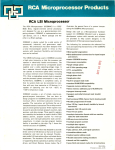
Design Details. The heart of the Elf microcomputer is the new RCA CDP1802
COSMAC microprocessor chip that sells for less than $30. The chip can use any
combination of standard RAM and ROM devices and can address up to 65,536 (65
k) bytes of memory. It has flexible programmed I/O and program-interrupt modes,
an on-chip DMA (direct memory access), four I/O flag inputs directly tested by
branch instructions, and a 16 x 16 matrix of registers for use as multiple program
counters, data pointers, or data registers.
Other features of the 1802 chip include voltage operation between 3 and 12 volts
dc at very low current drain, TTL compatibility, built-in clock, and simplified
interfacing. There is also a built-in program loading capability that allows you to
load a sequence of bytes without having to toggle in a new address for each byte.
No ROM is required for the minimum trainer system described here. The multiple
program counters permit some interesting programming "tricks," and the many
single byte instructions keep programs short.
A block diagram of the Elf system is shown in Fig. 1. The pinout for the 1802
microprocessor chip is shown in Fig. 2.
Fig. 1. Block diagram of basic computer. Up to 65K bytes of memory, 91
instructions, and varied I/O ports can be added as the system grows.
3
Fig. 2. Pin out for the CDP1802 COSMAC microprocessor.
Basic Operation. The key to understanding the computer is the method used for
addressing the memory. At first, the procedure may appear to be complicated, but
you will soon see that it is not difficult.
The 1802 chip contains 16 general-purpose registers, each holding 16 bits (two
bytes) of memory addresses for data. The registers are labeled R0 through RF to
conform to the hexadecimal numbering system, as shown in Fig. 3. (In the
diagrams, and in computer technology in general, a Danish zero -- a zero with a
slash through it -- is used to distinguish zero from a capital letter O.) Hence, if we
refer to the low-order, or least-significant, byte of R1, we can call it R1.0, while
the high order byte of RF would be called RF.1.
Fig. 3. The 16 registers in the 1802 are labelled R0 through RF (hex).
There is also an 8-bit D register that is used to move bytes around. In the
instruction set shown in part in the instruction Subset Table, note that the 8N (8
with a digit) code will copy a low order general register byte into register D.
Writing this instruction as 81 in a program will cause R1.0 to be copied into D
when the instruction is executed. We can then use instruction BF (BN in the table,
with B and a digit) to copy the D byte into RF.1. It takes two bytes, 81 BF, to
transfer a byte from R1.0 to RF.1 via temporary holding register D. The byte in D
4
can also be used in arithmetic operations performed by the ALU (arithmetic logic
unit) circuits.
There are three other important registers that are labelled N, P, and X. Each can
hold a 4-bit digit that is used to select one of the 16 general-purpose registers. For
example, if you wanted to talk about the general-purpose register selected by the
hex digit in X, you would call it RX. If you wanted just the low-order byte of RX,
call it RX.0. RN would refer to the general-purpose register designated by the 4bit digit currently contained in N; if the digit is 4, RN = R4.
The general-purpose registers can contain 16-bit memory addresses. Suppose
register R3 contains data 0012. M3 would mean the memory location specified by
the contents of R3, and M(0012) means memory location 0012 directly. MX
means the memory location addressed by the contents of the general register
selected by the current digit in X. If X = 3, MX = M3; if R3 = 0012, MX = M3 =
M(0012).
Since the basic computer has only 256 bytes of memory, we use just the low-order
bytes of the general registers to address the memory. In expanded-memory
systems, you can use the high-order bytes of the general-purpose registers to select
individual 256-byte pages of random-access memory (RAM).
Fig. 5. Control circuits for the computer. Connections at right go to similarly
marked connections on main circuit.
5
Fig. 4. Complete circuit for the Elf computer. Identified connections on the left go
to the "front panel" with the eight data switches. The remaining can be left
"floating" at 1802, or tied to terminal strip.
PARTS LIST
C1, C2--10-µF, 16volt electrolytic capacitor
C3, C4--30-pF disc
capacitor
D1 through D6--IN914
switching diode
IC1--CDP1802
COSMAC
microprocessor chip
(RCA)
IC2, IC3--2101 (256 x
4) static RAM IC
IC4, IC5--4050
noninverting hex buffer
IC
IC12--4013 dual D flipflop IC
IC13--LM309K 5-volt
regulator IC
LED1--Red lightemitting diode
R1 through R9-47,000-ohm, ¼-watt
resistor
R10--470-ohm, ¼-watt
resistor
R11--10-megohm, ¼watt resistor
S1 through S11--Spdt
toggle switch
6
5½" x 2" (14 x 5.1cm)
piece of thin aluminum;
¾" x 3/8" (19.1 x 9.5 cm)
pine for chassis rails; 14pin IC sockets (4); 16pin IC sockets (3); 22pin IC sockets (2); 40pin IC socket; connector
for power supply; 9-volt,
350-mA dc power
source; 1¼" x ¾" x 1/8"
(31.8 x 19.1 x 3.2 mm)
piece of aluminum; drytransfer lettering kit;
machine and wood
IC6, IC7--Hex LED
display (H-P No. 50827340)
IC8, IC9--4016 quad
bilateral switch IC
IC10--4023 triple 3input NAND gate IC
IC11--4049 inverting
hex buffer IC
S12--Pushbutton switch
with one set each
normally open and
normally closed contacts
XTAL--1-to-2-MHz
crystal (see text)
Misc.--5½" x 4" (14 x
10.1cm) perforated board
with 0.1" (2.54 cm) hole
spacing;
hardware; hookup wire;
solder; etc.
Note: the CDP1802
COSMAC
microprocessor chip is
available from any RCA
parts distributor as is the
COSMAC user manual.
The memory contains both instructions and data bytes. Instruction bytes tell the
computer what to do with the data bytes. One-byte instructions have two hex
digits, where high-order bits 7, 6, 5, and 4 tell the computer what type of operation
to perform. Low-order bits, 3, 2, 1, and 0 are usually placed in the N register when
a new instruction is fetched from memory.
Any one of the general-purpose registers can be used as a program counter. The
program counter addresses instruction bytes in memory. Each time an instruction
is fetched from memory, the program counter is automatically incremented so that
it points to the next instruction to be fetched. Branch instructions can be used to
change the address in the program counter to permit jumping (branching) to a
different part of the program when desired. The digit in the 4-bit P register
specifies which 16-bit general-purpose register is being used as the program
counter.
Timing Sequence. Since many of the 1802 microprocessor's instructions are only
one-byte long and require two machine cycles, the first cycle is always an
instruction fetch, or memory read. The fetched instruction is executed during the
next machine cycle, which could be a memory-read memory-write, or registertransfer type of cycle.
Program execution always consists of a sequence of fetch-execute cycles, and the
two SC0 and SC1 lines (see Fig. 4 and Fig. 5) indicate what type of cycle is being
performed according to the following criteria:
SC1
0
0
1
1
SC0
0
1
0
1
Type of Machine Cycle
instruction fetch
instruction execute
DMA in/out
interrupt
Direct memory access (DMA) and interrupt are special types of cycles, which we
will discuss later.
Circuit timing is shown in Fig. 6.
7
Note that each machine cycle requires eight clock pulses.
Fig. 6. Microprocessor timing. One machine cycle requires eight clock pulses.
TPA and TPB control various functions, both on and off the computer.
The microprocessor has an internal single-phase clock circuit. Connecting a
crystal between pins 1 and 39 of the 1802 chip causes the clock to run
continuously. If desired, XTAL, C3, C4, and R11 can be omitted and an external
clock with a 5-volt swing can be substituted between pin 1 and ground.
During each machine cycle, timing pulses TPA and TPB are available at pins 33
and 34 of the 1802. TPA occurs at the beginning of each machine cycle and can be
used to clock the high-order byte of a 16-bit memory address into a memory pageselection register. Note that the 1802 sends out memory addresses as two 8-bit
bytes. The high-order byte appears on address lines A0 through A7 first. Then the
low-order byte is held on the A0 through A7 lines for the remainder of the
machine cycle. This low-order address byte can, by itself, specify one of 256
locations in the minimum 256-byte memory.
TPB occurs toward the end of the machine cycle and is used to clock a byte from
the RAM into an output device (such as the hex display used here). An input byte,
to be stored in the RAM, is gated to the bus for the duration of the input (memorywrite) machine cycle so that no time pulse is needed for input bytes.
The ~MREAD line is low during any memory-read machine cycle. When low, it
opens the pin-18 RAM data output gates of IC2 and IC3, permitting the byte
stored in the RAM location addressed by A0 through A7 to appear on the data bus.
The RAM's access time is such that the output byte appears on the bus prior to
TPB. The bus byte from the RAM can then be clocked into an internal register of
the 1802 or clocked to an external register (such as the hex display) with TPB,
depending on the type of instruction being executed.
[Note: The ~MREAD above has a line over the MREAD instead of using the tilde,
in the article. However, there isn't any HTML tag to put a line over characters, so
I'm using the tilde convention instead. The overhead line, or tilde represent activelow signals.]
When the 1802 is performing an instruction cycle that requires a byte to be stored
in the RAM, the ~MREAD line is held high to disable the RAM output bus gates.
The microprocessor then causes the byte stored in the RAM to be gated onto the
bus during the memory-write cycle. This byte can come from an internal register
of the 1802 or from an input device such as switches, depending on the type of
8
instruction being executed. The 1802 then generates a low memory-write pulse
(~MWR) that causes the bus byte to be stored in the RAM location addressed by
the A0 through A7 lines.
Circuit Operation. Using Fig.4, Fig.5, and the Instruction Subset Table we can
now discuss the logic of the Elf microcomputer. The RAM access is sent out on
lines A0 through A7. Eight tri-state bidirectional bus lines are used to transfer the
data bytes back and forth between the 1802's registers and the IC2-IC3 RAM. A
RAM byte can be transferred to hex displays IC6 and IC7 via the data bus using
IC4 and IC5 to supply the current drive for the displays. Displays IC6 and IC7
contain latches to store the display byte.
The basic clock frequency of the processor is determined by XTAL which should
not go above 2 MHz in this circuit. The ~MREAD and ~MWR lines control the
read and write cycles of the RAM, while TPA and TPB provide the timing pulses.
TPA can be used for memory expansion address latching. TPB to clock bytes into
output circuits. SC0 and SC1 indicate the type of cycle being performed by the
1802.
The N0, N1, and N2 lines are used to select input or output devices in the Elf,
selection can be made among four input and four output devices. The table details
the values of the N0, N1, and N2 lines during the machine cycle in which an input
or output instruction is executed. Instructions 69, 6A, 6B, 61, 62, and 63 are spares
that can be used to add I/O devices or ports to the computer. When 6C is executed,
the N2 line goes to a logic-1 state and the bus byte is written into the RAM. Since
this is a write cycle, ~MREAD will be high. With both N2 and ~MREAD high,
the output of gate IC10C will be low, putting the input toggle switch byte on the
bus so that it can be stored at the memory location addressed by RX. This input
byte will also be placed in the 1802's D register.
When a 64 instruction is executed, N2 is high and ~MREAD is low, making the
output of IC10C high and preventing the input switch byte from getting onto the
bus. Instead, gate IC10B generates an output clock pulse with TPB that clocks the
RAM output byte into the hex display.
The four external flag input lines– EF1, EF2, EF3, and EF4–can be pulled low by
external switches. These four lines can be tested by instructions 34, 3C, 35, 3D, 36,
3E, 37 and 3F. Note in Fig. 5 that the INPUT pushbutton switch, debounced by
portions of IC11, is connected to the ~EF4 line. This means that ~EF4 = 1 when
S12 is depressed and ~EF4 = 0 when S12 is in its normal position.
Latched output line Q can be set high by a 7B instruction or reset to low by a 7A
instruction. The Q LED comes on when Q is high. The ~DMA~IN, ~DMA~OUT,
and ~INTERRUPT lines can be pulled low to cause these operations to occur.
9
ONE BYTE INSTRUCTIONS
TWO BYTE INSTRUCTIONS
1N RN+1
30MM GO TO MM
2N RN-1
31MM GO TO MM IF Q=1
8N RN,0–>D
39MM GO TO MM IF Q=0
9N RN,1–>D
32MM GO TO MM IF D=00
AN D–>RN.0
3AMM GO TO MM IF D != 00
BN D–>RN.1
33MM GO TO MM IF DF=1
4N MN–>D,RN+1
38MM GO TO MM IF DF=0
5N D–>MN
34MM GO TO MM IF EF1=1
DN N–>P
3CMM GO TO MM IF EF1=0
EN N–>X
35MM GO TO MM IF EF2=1
7A 0–>Q (LIGHT OFF)
3DMM GO TO MM IF EF2=0
7B 1–>Q (LIGHT ON)
36MM GO TO MM IF EF3=1
F0 MX–>D
3EMM GO TO MM IF EF3=0
F1 MX or D–>D
37MM
GO TO MM IF EF4=1 {IN
SWITCH
F2 MX and D–>D
3FMM
GO TO MM IF EF4=0 {IN
SWITCH
F3 MX xor D–>D
F8KK KK–>D
F6 SHIFT D RIGHT, BIT 0–>DF
F9KK KK or D–>D
76
ROTATE D RIGHT, DF–
>B7,B0–>DF
FAKK KK and D–>D
FE SHIFT D LEFT, BIT 7–>DF
7E
FBKK KK xor D–>D
ROTATE D LEFT, DF–>B0,B7–
>DF
FDKK KK-D–>D,CARRY–>DF
F5 MX-D–>D,CARRY–>DF
FFKK D-KK–>D,CARRY–>DF
F7 D-MX–>D,CARRY–>DF
FCKK KK+D–>D,CARRY–>DF
F4 MX+D–>D,CARRY–>DF
7CKK KK+D+DF–>D,CARRY–>DF
ONE BYTE INPUT
INSTRUCTIONS
1-BYTE OUTPUT
INSTRUCTIONS
N2 N1 N0
N2 N1 N0
69 BUS–>MX,D
0
0
1
61 MX–>BUS,RX+1
0
0
1
6A BUS–>MX,D
0
1
0
62 MX–>BUS,RX+1
0
1
0
6B BUS–>MX,D
0
1
1
63 MX–>BUS,RX+1
0
1
1
1
0
0
64
1
0
0
6C
INPUT SWITCH
BYTE–>MX,D
MX–>HEX
DISPLAY,RX+1
Table 1. Instruction Subset Table shows required sequence of steps.
10
The ~LOAD and RUN lines control the operation of the microprocessor according
to the following conditions:
~LOAD RUN Mode
gnd
gnd
load
+5V
gnd
reset
gnd
+5V –
+5V
+5V run
RUN and LOAD switches S1 and S2 in Fig. 5 control the operation of the
computer. With both switches set to OFF, ~LOAD is +5V and RUN is at ground
potential. This resets the 1802. Neither TPA nor TPB are generated in the reset
state and R0 = 0000, P = 0, X = 0 and Q = 0 after the 1802 is reset. When the
LOAD switch is set to ON, ~LOAD goes low and RUN stays low, forcing the
system into the load mode. Now you can load a sequence of bytes into the RAM,
starting at address 0000, by setting the bytes into the input toggle switches, one at
a time, and operating the INPUT switch.
In the load mode, the 1802 does not execute instructions but waits for a low to
appear on the ~DMA~IN line. When this happens, the 1802 performs one memory
write cycle during which the switch input byte is stored in memory. R0 is used to
address memory. during the DMA IN cycle. After the input byte is stored at the
address specified by R0, this register is incremented by one so that input bytes will
be sequentially loaded into RAM locations. Line SC1 goes high during the DMA
IN cycle so that the control circuits know when the input byte has been stored in
the RAM.
Fig. 7. Program turns on Q-LED when INPUT switch is operated.
11
INTRODUCTION TO PROGRAMMING
Once you have built your Elf, you must
learn how to load a sequence of bytes
into memory and then go back and
display the sequence. Let us write a
simple program that can be loaded into
the memory and run.
Suppose you want to program the
computer to turn on the Q LED whenever
the INPUT switch is set to ON. First, you
must draw a flow chart that shows the
required sequence of steps (Fig. 7).
Locate the correct instructions in the
Instruction Subset Table. A 7A
instruction will perform Step 1. Load this
instruction into M(0000). Note that when
the INPUT switch is not depressed, EF4
= 0. A two-byte 3F 00 instruction will
jump (branch) back to the 7A instruction
at M(0000) as long as the INPUT switch
is not operated (EF4 = 0). This condition
is known as a "loop," and the program
will stay in this loop while it is waiting
for the INPUT switch to be depressed.
Load 3F 00 into memory locations
M(0001) and M(0002) to perform the
second step in the flow chart. All GO TO
MM instructions shown in the Table put
MM into the low-order byte of the
program counter if a GO TO condition
exists. Otherwise, the next instruction in
sequence is fetched by the 1802.
for the hex number 7A, and depressing
the INPUT switch. Release the INPUT
switch, insert 3F and operate the INPUT
switch again. Then load 00 and so on
until the last byte, 01, has been stored at
M(0005). If you "blow" the program, set
MP to ON and LOAD to OFF. Then set
LOAD to ON and operate the INPUT
switch until you get to the byte
immediately preceding the wrong entry.
Set MP to OFF, set up the correct byte,
and operate INPUT. Flip MP back to
ON to protect what you have stored in
memory.
To start the program running, set LOAD
to the down position to reset the 1802
and set the RUN switch to ON. Nothing
should happen until you depress the
INPUT switch, at which time the Q
LED should come on. Releasing the
INPUT switch should cause the LED to
extinguish. If you like, you can now
observe the timing signals of the 1802
on an oscilloscope while the program is
running.
Another simple program involves
counting the number of times the
INPUT switch is operated and then
turning on the Q LED at the end of the
count. The flow chart for this program is
Loading a one-byte 7B instruction into
shown in Fig. 8. When you load and run
M(0003) takes care of Step 3, while a 30 this program, nothing will happen until
01 instruction will jump back to the 3F
you operate the INPUT switch five
00 instruction at M(0001). Load the 30
times, at which point the LED will come
01 instruction at M(0004) and M(0005)
on and remain on. Note in Step 1 that
to complete the program.
you can change the number of times the
You load this 6-byte program by placing INPUT switch is operated. Step 6 just
loops on itself to terminate the program
the LOAD switch on the ON position,
with RUN and MP set to OFF, setting up after the INPUT switch has been
operated the specified number of times.
the toggle switches
12
Depressing and releasing INPUT switch S12 sets flip-flop IC12 (Fig. 5). The ~Q
output of this stage goes low, causing the required low on the ~DMA~IN line. The
1802 responds to this request with a memory-write cycle during which SC1 is
high. During this cycle, ~MREAD is high and, since LOAD switch S2 is also ON,
the N2/LOAD signal causes gate IC10C to go high, gating the switch input byte to
the data bus and storing it in memory. When SC1 goes high, it also resets IC12,
which causes ~DMA~IN to return to its high state. The computer then waits for
the next switch input byte and LOAD switch operation.
Following each DMA IN cycle, the 1802 holds the A0 through A7 lines at the
address of the byte just stored in the RAM. ~MREAD is also held low while
waiting for the next input byte. This means that the previously loaded byte is
being gated to the bus (from the RAM) while waiting for a new byte. This bus
byte is continuously clocked into the hex display, since the LOAD switch is
holding IC10B open.
Fig. 8. Program counts number of times INPUT switch is operated.
A sequence of program bytes can be loaded into the RAM starting at M0 =
M(0000) by setting the LOAD switch to the ON position, with the RUN switch set
to OFF. Set the eight input switches, S4 through S11, to the desired byte code (in
hexadecimal) and depress the INPUT switch to store the byte in the RAM. The
value of this byte will be displayed with the hex displays IC6 and IC7. Repeat this
procedure for each byte to be loaded. Setting the LOAD switch to OFF puts the
13
1802 back in the reset state where R0 = 0000, P = 0, X = 0, and Q = 0. If you wish
to see what is stored in memory, set MP (memory-protect) switch S3 and the
LOAD switch to ON. Now, each time you operate the INPUT switch, successive
bytes in the RAM, starting with M(0000), will be displayed.
To change a byte, proceed to the byte just before the one to be changed. Flip the
MP switch to OFF, set the input toggle switches to the hex value of the new byte,
and depress the INPUT switch once. This new byte will be displayed and stored in
the RAM at the location following the byte at which you stopped. Place the MP
switch in the ON position. You can now continue to operate the INPUT switch to
sequence through the RAM without modifying the bytes in memory.
To start the executive cycle of a program, set both the LOAD and RUN switches
to OFF (to reset the 1802). Then set the RUN switch to ON. The program counter
is always specified by the hex digit in register P, which can be set to zero by reset
so that the program counter will always initially be R0. Set R0 to 0000 by
resetting so that instruction fetching, or program execution will always begin at
M(0000). Instructions will continue to be fetched from the RAM and executed
until the RUN switch is set to OFF, resettting the computer. Make sure that the
MP switch is OFF when running programs so that computer operation is not
inhibited.
Construction Notes. Hardware assembly is relatively simple, permitting the
project to be put together with ordinary perforated board with 0.1" (2.54-mm) hole
spacing and IC sockets, using either Wire Wrap® or a wiring pencil. (See photo.)
The perf board measures 5½"L × 4"W (14 × 10.2 cm) and is supported on a base
made up of lengths of ¾" × 3/8" (19.1 × 9.5) pine. A sheet of thin aluminum
provides the support for the eight toggle-type data switches. The LM309 voltage
regulator IC (IC13) is mounted on a 1¼" × ¾" × 1/8" (31.6 × 19.1 × 3.2-mm)
piece of aluminum to serve as a heat sink.
Do not mount the IC's (except the display devices) in their sockets until after all
wiring is complete. Socket, switch, and component layout should be roughly the
same as shown in the photo. Be sure to locate the crystal close to pins 1 and 39 of
the microprocessor's socket. Then wire the circuit in accordance with the
schematics in Figs. 4 and 5.
Any crystal with a frequency of between 1 and 2 MHz can be used in the Elf, or
you can substitute a simple 555 or CMOS oscillator with a 5-volt signal swing
between pin 1 of the 1802 and circuit ground, in which case, you will have to omit
XTAL, C3, C4, and R11. There is no lower limit to the clock frequency, but most
of the sample programs discussed in this series of articles are based on a clock
frequency between 1 and 1.8 MHz.
Displays IC6 and IC7 are relatively expensive hex devices. They are the only TTL
devices in the computer and, as a result, draw most of the power required by the
circuit. If you wish to economize, you can substitute ordinary LED's for the
displays. (Next month, we will discuss how to make the substitution.)
An inexpensive 9-volt, 350-mA dc battery eliminator, like those used as battery
charger/eliminators for calculators, can be used to power the Elf.
14
When the computer is completely assembled, use a dry-transfer lettering kit to
label all switches and positions. IC socket locations, and pins 1 of all sockets.
Then, exercising the usual safety procedures for handling MOS devices, install the
integrated circuits in their respective sockets.
Coming Up. In future articles, we will provide more programs as well as methods
of adding other types of inputs and relay-control output circuits. We will also
detail how to save programs in battery-powered COSMOS RAM's and describe a
simple operating system that lets you read/write any memory location and inspect
general register contents for program debugging purposes. Memory expansion,
hex keyboard input, and an inexpensive video graphics display are other subjects
we will cover in detail.
15
Build The COSMAC "ELF" A Low-Cost
Experimenter's Microcomputer
Part 2
Some hardware improvements and more programming details
BY JOSEPH WEISBECKER
Last month, we discussed the construction of the low-cost Elf
microcomputer/trainer and gave some examples of simple programming. This
month, we will describe hardware and how to make a low-cost LED replacement
for the relatively expensive hex display and add a simple 8-bit I/O port. Then we'll
add a 16- switch monitor that among other things will allow you to use a hex
keyboard. We'll finish up the hardware section by showing how to use a 9-volt
battery as power for a RAM circuit to hold a program for as long as six months.
When we're finished with the hardware details, it's back to the software continuing
with our programming discussion.
16
The Hardware. The hex displays called for in the original Elf project can be
replaced with a discrete LED circuit as shown in Fig. 1. You will need a CD4508
eight-bit register, eight low-current LED's, two 4049 hex inverters, and eight 470ohm, ½-watt resistors. When the LED circuit is substituted for the hex displays,
current consumption will be reduced by about 150 mA. The input comes from the
data bus which formerly went to hex displays IC4 and IC5.
When you use the LED display, you must count the LED's to arrive at the hex
number displayed. The upper four LED's form the first digit, the lower four, the
second digit.
You can mount the LED's on the front panel. Be sure you carefully identify each.
Also, when making the conversion, don't forget to modify the RUN switch circuit
as shown.
You can connect an inexpensive cadmium-sulfide (CdS) cell between the EF1 line
and ground. Be sure to use a photocell that has a dark resistance in excess of
200,000 ohms and a light resistance of less than 10,000 ohms. If you use any other
photocell, you may have to increase the value of the resistor to pull up the EF1
line of the 1802 microprocessor. The high input impedance of the CMOS logic
eliminates the need for photocell amplification. Also several photocell inputs can
be used, each connected to a different flag (EF) line.
Using a photocell input, you can program the computer to start counting when an
object moves past one photocell and stop counting when the object passes a
second cell. This technique allows you to determine the speed of a moving object.
It can also be used to count people, monitor motor speed, provide targets in a
computer-controlled light gun or "eyes" for a computer-controlled robot, etc.
Magnetic reed switches, simple make/break switches, or similar devices can be
connected to the computer via the flag-line inputs.
Several inexpensive methods of expanding the number of input and output lines
can be used with this computer. One example is shown in Fig. 2. Here, a CD4058
IC is used in both the input and the output positions, while other IC's provide the
necessary gating. A 69 instruction will store the values of the eight input lines in
memory as a single byte.
In the output port section, a 61 instruction sets a memory byte into this port. The
output port can control up to eight output lines, but you will have to add
CD4050/CD4049 buffers if you wish to drive TTL loads. You can use these
output lines to drive suitable transistors to control relays, lamps or LED's, or
battery-powered motors, you can have the computer sequence lights, control
animated displays or robots, or control a slide projector in response to tones from
an audio tape. You can use the existing Q line output in the same manner for a
single operation.
17
Fig. 1 (9) Circuit for a discrete LED display.
Fig. 2.(10) A way to expand the number of input and output lines using two
CD4508 integrated circuits.
18
A simple method of controlling up to 16 output lines or monitoring the states of 16
switches is shown in Fig. 3. A 62 instruction will set the low-order digit of a
memory byte into the 4-bit CD4515 register. The output line corresponding to this
digit will go low, while the other 15 remain high. To make things more interesting,
the computer can determine whether the switch attached to the selected output line
is closed or not by testing EF2 with a branch instruction.
Fig. 3.(11) A method of controlling up to 16 outputs.
The following program continuously examines all 16 switches in sequence and
stops with the number of any closed switch from 0 to F in the low-order digit of
R3.0:
Step
1
2
3
4
5
M
0000
0003
0006
0008
000A
Bytes
F8 FF A2
13 52 E2
62 22
3D 03
30 0A
Comment
FF-->R2.0 (memory pointer)
R3 + 1, R3.0-->MX, 2-->X
MX-->CD4515 (select switch)
Repeat step 2 if switch is open
Stop with R3.0 = closed switch number
The diodes can be omitted if only one switch at a time will be closed. This circuit
and an appropriate program could permit data and instruction bytes to be loaded
into memory a digit at a time from a hex keyboard instead of toggle switches.
Switch debouncing could be performed with a programmed delay following each
key depression. A 64-character keyboard could be used by treating it as four
groups of 16 keys each, with the common side of each key group connected to a
different flag line. In fact, a program to generate the Morse code equivalent of
each key could be written using the Q line as the output.
This circuit can also be used to select one of 16 external devices or I/O ports if
desired. Using the latter technique would permit up to 128 I/O lines. Cascading
CD4515's would permit even larger numbers of I/O lines to be handled.
A low-cost video terminal can be made using the "Scopewriter" (POPULAR
ELECTRONICS, August 1974), or you can interface your computer with a
cassette data interchange system.
19
We have only scratched the surface of I/O circuits for the Elf. The real fun (and
program training) starts when you think of new things to attach to the output lines
and start writing programs to activate them.
The major drawback with a RAM, or memory, system is that data stored in it is
erased when the main power source is shut down. (Of course, if you could use a
ROM, this wouldn't be a problem. However, ROM's must be preprogrammed with
the memory data you wish to save, a costly and time-consuming approach.)
Adding a cassette interface doesn't entirely eliminate the problem because a
"bootstrap" is still required to be stored in memory to run the cassette.
The use of low-power COSMOS RAM IC's and a 9-volt mercury battery, as
shown in Fig. 4, will allow you to save programs in memory for up to six months
even with the main power to the computer turned off. The 1822 RAM's shown are
in-compatible with the 2101's specified for the original project, but some of the
RAM's must be rewired as shown.
With the COSMOS RAM's installed, you can turn off power to the computer at
any time. The mercury battery will supply the required standby power to the
memory system so that the program will be ready to run immediately when the
computer is again powered up. The newly added STANDBY switch should be
turned on (+5 volts) only after power is turned on. It should be off to hold pin 17
of the RAM's at ground potential before removing power from the system.
Fig. 4.(12) Using a low-power COSMOS RAM and a 9-volt battery permits saving
programs in memory.
Periodically check the battery's output; if it should fall too low, the memory
system won't be able to hold data.
20
The last piece of hardware we will discuss here is the simple output driver shown
schematically in Fig. 5. This is a conventional driver for almost anything that
doesn't require more current than the transistor is capable of safely handling. The
diode in the relay circuit removes the reverse transient spike that might otherwise
damage the transistor. You can substitute a LED or even a load resistor for driving
a power stage.
More Programming. The single-line output program shown below is a simple
program that will flash the Q LED at a preset rate. It also provides a
programmable square wave on the Q line.
Step
1
2
3
4
5
6
7
8
M
0000
0001
0004
0005
0006
0008
000A
000B
Bytes
7A
F8 10 B1
21
91
3A 04
31 00
7B
30 01
Comment
0-->Q
10-->R1.1
R1.1
R1.1-->D
Repeat step 3 if D = 00
Go to step 1 if Q = 1
1-->Q
Go to step 2
When you run this program, the square-wave frequently depends on the settings of
the input switches. You can change frequency at any time. For higher frequencies,
change B1 at M(0006) to A1 and 91 at M(0008) to 81. You can now select any of
256 different frequencies by altering the settings of the switches.
To modify the program to sweep the audio frequency range, use the following
program:
Step
1
2
3
4
5
6
7
8
9
M
0000
0003
0004
0006
0008
000A
000C
000F
0011
Bytes
F8 FF A2
7A
82 A1
21 81
3A 06
31 03
7B 22 82
32 00
30 04
Comment
FF-->R2.0
0-->Q
R2.0-->D; D-->R1.0
R1.1; R1.0-->D
Repeat step 4 if D = 00
Go to step 2 if Q = 1
1-->Q; R2.1; R2.0-->D
Go to step 1 if D = 00
Go to step 3
This program can be used in audio test applications. Note that R2 is used as a
second counter that causes the square-wave frequency to change after each cycle.
You can hear what this sounds like by using the circuit shown in Fig. 5.
Very low frequency square waves or long-interval timing, can be programmed by
cascading counters as illustrated in the following flow chart:
21
The Q line can then be used to activate a relay (as in Fig. 5), which can control
house lights, motors, etc.
Suppose you wish to program a variable-pulse generator instead of square-wave
generator. Use separate counts for the pulse off and on times as illustrated in the
following flow chart:
This program will flash the Q LED and put a square wave on the Q line at a rate
determined by the contents of memory M(0002) from a 10 to some other number.
By referring back to the instruction Subset Table in last month's article, you
should be able to interpret the above program.
Note in the program that R1 is used as a 16-bit decrementing counter (steps 3, 4,
and 5). When the high- order eight bits of this counter reaches 00, the Q line goes
to its opposite stage. Changing steps 2 and 4 to use the low-order byte of R1
increases the Q line's output frequency by a factor of 256.
If you use a 1-MHz crystal in the clock, the above program can generate square
waves at frequencies between 0.3 and 80 Hz, depending on the byte in M(0002).
22
By changing the B1 instruction at M(0005) to 81, square waves between 80 and
20,000 Hz can be generated. In this manner, your basic computer becomes a
presettable square-wave generator.
We can rewrite the program so that the square wave's frequency becomes a
function of the settings of the toggle switches as follows:
Step
1
2
3
4
5
6
7
8
M
0000
0003
0004
0005
0007
0009
000B
000D
Bytes
F8 FF A2
E2
7A
6C B1
21 91
3A 07
31 04
7B 30 05
Comment
FF-->R2.0
2-->X
0-->Q
Switch byte-->MX, D:D-->R1.1
R1.1; R1.1-->D
Repeat step 5 if D = 00
Go to step 3 if Q = 1
1-->Q; Go to step 4
Fig. 5.(13) Circuit to provide outputs used for testing
In a similar manner, you can program bursts of pulses, variable-interval pulse
trains, etc. You can even write a program where a list of bytes specifies a
sequence of different tones to make a programmable music box.
The following two programs are "games" that demonstrate how the COSMAC
instructions can be used. No added I/O circuits are required to run these programs.
23
Load the following sequence:
Step
1
2
3
4
5
6
7
8
M
0000
0001
0004
0005
0007
0008
000B
000D
Bytes
E1
F8 0F A1
64
3F 05
6C
F8 0A F7
51 64
30 0D 00
Comment
1-->X
0F-->R1.0
MX-->display; X + 1
Wait for INPUT switch to be depressed
Switch byte --> MX,D
0A-->D; D-MX-->D
D-->M1; MX-->display; X + 1
Stop; 00
Set both the LOAD and MP switches to off then flip RUN to on. Have someone
select any digit between 1 and 9 multiply by 10, add the original digit. Set the
binary code for the least significant digit of the final answer into switches 3, 2, 1,
and 0, and place the other input switches in the down position. When you depress
the INPUT switch, the computer will display the unknown digit.
This program illustrates how to set a memory byte into the output display with a
6C instruction. Note the use of R1 as a memory pointer and the use of the binary
subtract instruction in step 6.
The following program makes the computer "think" of a byte, which you must
guess in no more than seven tries:
Step
1
2
3
4
5
6
7
8
9
10
11
12
13
14
15
16
17
18
19
20
M
0000
0002
0005
0007
000A
000C
000F
0011
0013
0016
0018
001A
001C
001E
0020
0022
0025
0027
0029
002B
Bytes
8A AB
F8 AA A3
53 E3
F8 07 A4
64 23
2A 3F 0C
37 0F
6C 8B
F5 33 1A
F8 01
30 22
3A 20
53 64
30 1E
F8 10
53 64 23
24 84
3A 0C
8B 7B
30 1C
Comment
RA, 0-->RB.0 = secret byte
AA-->R3.0 = memory pointer
D-->M3; 3-->X
07-->R4.0 = number of turns
M3-->display; 3 + 1; 3 - 1
RA + 1 until INPUT is depressed
Wait for INPUT to be released
Switch byte-->M3; RB.0-->D
M3-D-->D; Go to step 12 if M3 > RB.0
01-->D
Go to step 16 (show D)
Go to step 15 if D = 00
D-->M3; M3-->display; 3 + 1
Stop loop
10-->D
D-->M3-->display; 3 + 1; 3 - 1
R4-1, R4.0-->D (turn counter)
Go to step 6 if D = 00
RB.0-->D; 1-->Q
Go to step 13 (show D and stop)
Place both the MP and LOAD switches in the off position after toggling the
program. When you start the program by operating RUN; AA is displayed. Now,
try to guess what byte the computer has selected by setting the eight INPUT
switches and depressing the main INPUT switch. If 00 is displayed you guessed
correctly; if 01 is displayed, your guess is too low; if 10 is displayed, your guess is
24
too high. You lose after seven wrong tries, at which point, the computer turns on
its QLED and the displays indicate the hidden byte. To try again, set RUN to off
and then on.
The subtract instruction in step 9 sets an arithmetic overflow flag (DF) if MX is
equal to or greater than D. The COSMAC instruction manual covers a detailed
explanation of the use of this overflow flag in arithmetic and shift operations.
In Closing. Now that you have some familiarity with programming for the Elf,
look through your back issues of POPULAR ELECTRONICS for some
challenging programs to write. Try the "Logidex" game in the November 1973
issue, "Tug-of-War" game in February 1975, "Electronic Dice" in July 1975, and
the "Executive Digital Temper Countdowner" in December 1975. These are just a
few of the many electronic games you can program instead of building.
HEX NUMBER SYSTEM
Decimal
0
1
2
3
4
5
6
7
8
9
10
11
12
13
14
15
Binary
0000
0001
0010
0011
0100
0101
0110
0111
1000
1001
1010
1011
1100
1101
1110
1111
Hex
0
1
2
3
4
5
6
7
8
9
A
B
C
D
E
F
25
BY JOSEPH WEISBECKER
Build The COSMAC "ELF"
Microcomputer
Part 3:
How to expand memory, plus more programs
IN TWO previous articles (POPULAR ELECTRONICS, August 1976 and
September 1976), we discussed the construction of the low-cost Elf
microcomputer, gave some programming examples, and described some low-cost
optional input/output circuits. Here we will examine some software operating
systems and discuss adding 1024 bytes of memory for as little as $20.
Operating Systems. An operating system is a program that makes it easier to
program and use your computer. For example, if you want to change M(43) in the
basic Elf memory, you would have to start at M(00) and step through memory to
location 43 before you could change it. Program 1 is a simple opoerating system
for the Elf microcomputer. It lets you directly examine or modify any memory
location. It also allows you to start program execution at any memory location.
We call Program 1 ETOPS-256 (Elf Toggle OPerating System for 256-byte
memory). After loading ETOPS in RAM, it can be used to help you load and run
other programs.
To examine a memory location using ETOPS, set 01 into the toggles. Flip the
RUN switch up and 01 will be displayed. Now set the address of the memory byte
you want to examine into the toggles and push the INPUT switch. The next time
you push the INPUT switch, you'll see the selected memory byte displayed. Keep
pushing the INPUT switch to see the sequence of bytes stored in memory.
26
To modify any memory location, set 02 into the toggles and turn the RUN switch
up. 02 will appear. Set the address of the memory byte you want to modify (via
the toggles).
Push the INPUT switch and the Q light comes on. Now set the toggles to the value
of the byte you want to place in the selected memory location and push the INPUT
switch to store it in RAM. You can store a sequence of new bytes by setting each
byte into the toggles and pushing the INPUT switch. The Q light warns that you
are modifying memory.
If you have the toggles set to 00 when you flip the RUN switch up, you can then
set the toggles to the beginning address of a program you want to execute. Just
push the INPUT switch to start executing your program at the selected address.
Your program will begin execution with R3 as the program counter.
If you've added the battery RAM option to your system, ETOPS will be ready to
use as soon as you turn on power. Since ETOPS uses only 32 bytes, you still have
224 bytes available for your own programs.
Keyboard Systems. Adding a hex keyboard would make your Elf microcomputer
even easier to use, with 16 keys labelled 0 through F, you would have to press
only two keys for each byte you want to store in memory. In the second article, we
described a circuit for monitoring the status of 16 switches or keys. (See
POPULAR ELECTRONICS, Sept. 1976, page 38, Fig.3). If you add this circuit
and a 16-key hex keyboard, you can use Program 2--EHOPS-256 (Elf Hex
OPerating System for 256-byte memory). This program requires 74 bytes of RAM
so you still have 182 bytes left for your own programs. You can also use the hex
keyboard subroutine as part of your program if desired.
PROGRAM 1--ETOPS-256
0000
03
04
07
09
0B
0D
10
11
13
15
17
19
1A
1B
1D
1F
20
21
F8 20 A1
R1.0 = work
E1
X=1
6C 64 21
D = toggles
3F 07
Wait for IN on
37 09
Wait for IN off
32 1D
M(1D) if D=00
F6 33 11
M(11) if D=01
7B
Q=1
6C A1
R1.0 = toggles
3F 13
Wait for IN on
37 15
Wait for IN off
39 1A
M(1A) if Q=0
6C
M1 = toggles
64
Show M1, R1 + 1
30 13
Repeat M(13)
6C A3
R3.0 = toggles
D3
P=3
00
Work area
User programs from
M(21) to M(FF)
27
After loading EHOPS in memory, you can use it as follows. To load a byte into
any memory location from the hex keyboard, set the toggles to 02 and flip the
RUN switch up. The 02 toggles tell EHOPS that you want to store bytes in
memory. On the hex keyboard, press the most significant digit of a memory
address followed by the least-significant digit. This address byte will be displayed
and tells EHOPS where you want to start loading bytes in memory. You can now
load a sequence of bytes into memory via the hex keyboard. Just press the two
digits (most significant first) of each byte you want to load and they will be stored
sequentially in memory starting at the selected location.
0000
03
06
09
0C
0D
0F
10
equal')
12
14
17
19
1A
1C
1E
20
22
BSUB
23
24
26
28
2A
2D
2F
31
HSUB
33
36
39
3B
3D
40
41
43
45
46
48
PROGRAM
F8 FF
F8 23
F8 33
F8 0D
D3
D5 A1
6C
3A 14
81
F6
D5
64
30
D5
51
30
D3
D6
FE
FE
A0
80
64
30
F0
E2
FA
62
3D
7B
B4
24
3A
7A
35
30
A3
3B
E1
2--EHOPS-256
A2
R2.0 = work
A5
R5.0 = BSUB
A6
R6.0 = HSUB
A3
R3.0 = M(0D)
P=3
BSUB, R1.0=D
D, M2 = toggles
M(14) if D != 00 (Note: != means 'not
1C
17
E1
64
1C
FE
FE
D6
F1
22
22
D5
FC
0F
22
33
F8
94
41
46
31
52
01
52
09
R3.0 = R1.0
M(1C) if D=02
BSUB, X=1
Show M1, R1+1
Repeat M(17)
BSUB, X=1
M1=D, show M1, R1+1
Repeat M(1C)
P=3 (return)
HSUB
D left x 2
D left x 2
R1=D, HSUB
M2=R1 or M2
Show M2
Go to M(22)
D=M2, P=5
X=2, D+1
M2=D and 0F
Select key M2
M(33) if key off
Q=1, D=09
R4.1=09
R4-1
M(41) if R4.1 != 00
Q=0
Wait for key off
Go to M(31)
28
To examine any memory location (without changing its contents), set the toggles
to 01 before you flip the RUN switch up. Using the hex keyboard, enter the onebyte starting address of the sequence of memory locations you want to examine.
Press any hex key twice to step through memory and display the stored bytes.
To run a program you've loaded using EHOPS, set the toggles to 00 before
flipping the RUN switch up. Using the hex keyboard, enter the one-byte starting
address of your program. It will begin running with R3 as the program counter.
PROGRAM 3
0050
53
56
59
5D
60
61
64
F8
F8
E1
F0
F8
22
92
30
FF
00
64
FC
10
A1
51
21
01
B2
3A
56
60
51
R1.0 = work
M1=00
Show M1
M1+1
R2.1 = delay
R2-1
M(60) if R2.1 != 00
Repeat M(56)
EHOPS controls the hex keyboard with two subroutines called BSUB and HSUB.
BSUB calls HSUB by changing the program counter to R6 with a D6 instruction.
HSUB continuously scans all 16 hex keyswitches until one is pressed. It provides
a switch debounce delay and waits until the key has been released. It then returns
control to BSUB with the value of the pressed key in the least-significant digit of
the byte in D and M2.
BSUB is called by changing the program counter to R5 with a D5 instruction. It
waits until two hex keys have been pressed before returning control to the calling
program with the values of the two keys in the two digits of the byte in D and M2.
The most-significant digit represents the first key pressed. Any program you write
with R3 as the program counter can call BSUB to obtain a byte from the hex
keyboard. If you drive a speaker with the Q lines as described in the September
article, you will hear an audible click each time a hex key is pressed.
Program 3 can be loaded and run using either ETOPS or EHOPS: This program
continuously counts up at a rate determined by the byte at M(5E). Be sure to start
execution at M(50).
PROGRAM 4
*C0
F8
F0
AA
RA.0=F0
C3
F8
08
A8
R8.0=08
29
C6
D5
5A
BSUB, MA=D
C8
1A
28
A+1, R8-1
CA
88
3A
C6
M(C6) if R8.0 != 00
*CD
F8
F0
AA
RA.0=F0
D0
F8
08
A8
R8.0=08
D3
EA
F0
A7
R7.0=MA
D6
64
28
D8
F8
FF
D8
7B
87
Q=1, D=R7,0
DD
FF
01
D-01
DF
3A
DD
M(DD) if D != 00
E1
7A
87
Q=0, D=R7.0
E3
FF
01
D-01
E5
3A
E3
M(E3) if D != 00
E7
2C
8C
RC-1
E9
3A
DB
M(DB) if RC.0 != 00
EB
88
3A
EE
30
CD
Show MA, A+1, 8-1
AC
D3
RC.0=FF
M(D3) if R8.0 != 00
M(CD) if R8.0=00
F0-F7 = Table of tone values
Program 4 should be loaded and run using EHOPS. You should also have a
speaker attached to the Q line. Start this program at M(C0) with EHOPS. You can
then enter eight bytes via the hex keyboard. These bytes should have values
between 02 and 7F for best results. Each byte represents the frequency of a tone
you will hear via the speaker. After you enter the eighth byte you'll hear the eighttone sequence repeated over and over. You can restart the program at M(CD) to
hear a previously entered tone sequence.
30
Fig. 1.(14) Address latch. *Connect pin 19 of original 2101 RAM's to A10 instead
of ground.
PROGRAM 5
0000
F8
00
B1
R1.1=00
03
F8
FF
A1
R1.0 = work
06
F8
00
51
M1=00
09
E1
64
21
Show M1
0C
F0
FC
01
10
F8
10
B2
13
22
14
92
3A
17
30
09
51
M1+1
R2.1 = delay
R2-1
13
M(13) if R2.1 != 00
Repeat M(09)
An operating system can be designed to incorporate any desired feature. For
example, you might want to examine the contents of internal 1802 registers or
control the operation of a cassette recorder. As more features are needed, you may
want to dedicate the entire 256 bytes of memory in the basic system to your
operating system and add another section of memory for your other programs. The
256-byte operating-system memory can be battery powered and protected from
modification by the MP switch so that it is always ready for use.
31
Fig. 2.(15) Eight low-cost readily available 2102 RAM's (1024 x 1) and two
transmission gate packages.
Memory Expansion. You can add 1024 bytes of memory to an Elf
microcomputer using inexpensive, readily available 2102-type static RAM's as
shown in Figs. 1 and 2. The 10k bus pull-up resistors are required if the highoutput level of the RAM chips isn't at least 3 volts. Bits 0 and 1 of the high-order
address byte are clocked into the address latch with TPA (Fig. 1). These two
latched bits are used with the low-order COSMAC address byte to provide the
required 10-bit address for the 2102 RAM's. Bit 2 of the high-order address byte is
clocked into the address latch for use in selecting eith the original 256-byte RAM
or the added 1024-byte section of RAM. Disconnect pin 19 of the original two
2102 RAM chips from ground and connect to pin 12 of the 4042 address latch in
Fig. 1.
The original 256-byte memory will now be addressed as 0000-00FF and the new
1024-byte memory will be addressed as 0400-07FF. Since all of the previous
programs assumed one-byte addresses, they will not run in this expanded memory
system. Programs for systems with more than 256 bytes of memory must have
both the high-order and low-order bytes of address registers properly set. The
previous programs can be easily modified to run in the expanded system by
initializing both high- and low-order bytes of any 16-bit register used to address
memory. The foregoing counting program could be modified to run at M(0000) in
an expanded RAM system as shown in Program 5. In general, it adds only a few
bytes to program for an expanded-memory system. By adding bits to the address
latch of Fig. 1, you could address up to 64k bytes of RAM. Instead of addressing
extra memory, the high-order address bits could be used to select input/output
circuits or devices.
32
Don't forget that adding memory will increase system power requirements. As the
system is expanded, make sure your external power supply can handle the
increased current requirements. With this in mind, you'll find that the Elf can be
tailored to your needs at low cost. •
A READER'S ELF PROGRAMS
I recently constructed the COSMAC Elf described in your August (1976) issue
and thoroughly enjoyed the construction and testing of this microprocessor system.
I build approximately two projects a month that are illustrated in your magazine–
plus some from other sources. This particular project turned out to be the most
interesting I have ever constructed. Here are three programs that I found useful in
illustrating various system functions.
Program I is simply an expansion of your Q-light program with additional
decisions that alternately turn the Q light on and off when the input switch is
depressed.
Program II displays and increments successive hex characters each time the input
button is depressed. To do this, it was necessary to learn how to input to and
output from the memory, using pointers in registers, and also to do simple
arithmetic through the accumulator register (D register).
Program III plays SOS in Morse code. The program should be loaded through the
system switch registers if you have a half hour without interruption. With this
program, registers are used for pointers to subroutine loops set up for time delay.
Three subroutines for 0.5 second, 1 second and 3 seconds are established,
addressed by changing the program counter. The main program simply turns the Q
light on and off at intervals determined by the subroutines. The memory provided
in the basic Elf system (256 bytes) is enough for approximately 19 code elements.
Each code element requires only 10 instructions for an on and off interval in the
main program. The timing loops require the use of two registers to provide a
sufficient time. In my Elf, I used a 1-MHz crystal. Obviously, changing one
instruction in the loop subroutines will vary the time as necessary. Changing or
adding to the main program can change the code.
Try loading this program with the switch register if you have enough patience.
–Robert Klein
33
PROGRAM I
SWITCH ON AND OFF
3F
00
37
02
IF Q OFF GO TO 09
39
09
IF Q ON, TURN OFF AND
7A
RETURN TO 00
30
00
IF Q OFF, TURN ON AND
7B
GO TO 00
30
00
PROGRAM II
STORE DEPENDENT VARIABLE 00
E4
IN LOCATION 77 WITH POINTER
F8
IN R4--DESIGNATE R4 AS RX
77
A4
F8
00
54
34
STORE INDEPENDENT VARIABLE 01
F8
IN LOCATION 76 WITH POINTER
76
IN R5
A5
F8
01 (size of INCR)
55
DISPLAY AND DECREMENT RX
64
24
LOOK FOR INPUT SWITCH ON AND
3F
OFF
0F
37
10
ADD TWO VARIABLES AND PUT
05
RESULT IN LOCATION 77
F4 (F5 subtract)
(can be changed to subtract
54
to count down)
RETURN TO START OF LOOP
30
07
PROGRAM III
MAIN PROGRAM
7B
7B
D3
D4
7B
D3
35
INITIALIZE
F8
POINTERS
65 *
FIFTH DOT
F8
THIRD DOT
F8
F8
65 *
65 *
79 *
A3
A3
F8
7A
A4
79 *
D3
7A
A4
F8
D3
F8
65 *
F8
8D *
A3
65 *
THIRD DASH
A4
A3
7A
D3
F8
65 *
A3
A5
A3
7B
7B
7B
D3
FIRST DOT
F8
D4
7B
F8
D3
F8
79 *
F8
65 *
A4
A3
7A
A3
7A
D3
7A
D3
F8
D3
F8
65 *
F8
65 *
A3
65 *
D3
FIRST DASH
65 *
FOURTH DOT
65 *
SIXTH DOT, A3
PAUSE AND
7A
RETURN TO
D5
START
F8
8D *
A5
A3
A3
30
7B
00
7B
D3
D4
F8
* If a different
number of
F8
used,
SECOND DOT
65 *
starting address
A3
routine, or
7A
of memory
D3
flexibility is
79 *
SECOND DASH A4
36
code elements is
change the
7A
of each sub
D3
move to the end
F8
page if
F8
65 *
A3
65 *
A3
desired.
PROGRAM III
SUB ROUTINES (Must be loaded in order
indicated
after main program is
loaded.)
½-Sec Loop
1-Sec Loop
3-Sec Loop
All
instructions same as
½-Sec
Loop except where
indicated
PUT 256 IN REG #1
F8
.
.
FF
.
.
A1
.
PUT VARIABLE INTO
F8
.
REG #2
30 *
.
.
08 *
0F *
A2
.
.
C4
.
.
C4
.
DECREMENT AND LOOP THRU
C4
.
R1 UNTIL ZERO. THEN
C4
.
OUTPUT TO DECREMENT
C4
.
REG #2
21
.
81
.
.
.
.
.
.
.
37
3A
.
.
6B **
93 **
LOOP BACK TO START
22
.
R #1 CYCLE UNTIL
82
.
TOTAL TIME IS USED UP
3A
.
7F **
.
.
.
6B **
93 **
RETURN TO MAIN PROGRAM
D0
.
7F **
.
* Sets Time
** If a different number of code
elements is used, change this
instruction to starting
address of each subroutine
wait loop (first C4)
38
PE TESTED
BREAKTHROUGH PROJECT!
BY JOSEPH A. WEISBECKER
PART IV:
Build the PIXIE Graphic Display
Adding one chip to the Elf provides completevideo interface and animated
graphicscapability for less than $25.
If you own an Elf microcomputer (see POPULAR ELECTRONICS August 1976)
or are planning to build one soon, the addition of a single IC and a handful of
support components, and a change in the crystal frequency, can give you Pixie
graphics. The entire graphics system is built into the new CDP 1861 LSI chip that
sells for less than $20 from RCA parts distributors. (A complete kit is available;
see Parts List.) The two other IC's in the optional add-on system are for a crystal
oscillator that allows the graphics IC to generate the correct TV horizontal and
vertical sync pulses.
The photo at the top of this page illustrates what can be done with the original 256
bytes of memory in the Elf when the Pixie graphics system is added. In this article,
we will show you how to install and program the Pixie system to produce this type
of graphics.
Some Details. The unique Pixie graphics system employs the direct memory
access (DMA) capability built into the 1802 microprocessor in the Elf [42] to
work in conjunction with the new graphics IC. This allows you to display any
256-byte segment of memory on a CRT monitor or TV receiver. The output of the
new chip is a 1-volt composite video/sync signal.
39
The basic Elf project originally published in the August 1976 issue of POPULAR
ELECTRONICS is shown at left with the Pixie components added. Elf II is a
complete kit including a pc board, hexadecimal keypad, Pixie graphics
components and expansion bus (see Parts List).
Fig. 1. Memory addresses of bytes mapped onto TV screen in sample program.
The selected segment of memory appears on-screen as an array of small squares
that represent individual memory bits. If a memory bit is a 1, the appropriate
square will be white, while if a bit is a 0, the square will be dark. Changing the bit
pattern within the memory will change the pattern that appears on-screen. You can
store several different bit patterns (pictures) in memory and, [43]
TABLE I -- TEST PROGRAM
Label
Start
M
Bytes
Comments
0000 90 B1 B2 R1.1,R2.1=00
0003 B3 B4
R3.0,R4.0=00
0005 F8 2D A3 R3.0=(main)
0008 F8 3F A2 R2.0=(stack)
000B F8 11 A1 R1.0=(interrupt)
000E D3
P=3 (go to main)
40
Return
000F 72
restore D,R2+1
0010 70
restore XP,R2+1
Interrupt 0011 22 78
R2-1,save XP @ M2
0013 22 52
R2-1,save D @ M2
0015 C4 C4 C4 no-op (9 cycles)
0018 F8 00 B0
001B F8 00 A0 R0=0000(refresh ptr)
Refresh 001E 80 E2
----
D=R0.0
------
8 DMA cycles (R0+8)
0020 E2 20 A0 R0-1,R0.0=D
----
------
8 DMA cycles (R0+8)
0023 E2 20 A0 R0-1,R0.0=D
----
------
8 DMA cycles (R0+8)
0026 E2 20 A0 R0-1,R0.0=D
----
Main
------
8 DMA cycles (R0+8)
0029 3C 1E
go to refresh (EF1=0)
002B 30 0F
go to return (EF1=1)
002D E2 69
X=2,turn TV on
002F 3F 2F
wait for IN pressed
0031 6C A4
set MX,D,R4.0=toggles
0033 37 33
wait for IN released
0035 3F 35
wait for IN pressed
0037 6C
set MX,D=toggles
0038 54 14
set M4=D,R4+1
003A 30 33
go to M33
using software, display them successively onscreen to produce animation effects.
Low-resolution alphanumerics can also be created.
Since the basic Elf has only 256 bytes of memory, we will show how to display
the entire memory on the screen. The memory is mapped as shown in Fig. 1, in an
array of 64 spots wide (eight bytes with eight bits/byte) by 32 spots high to make a
total of 256 bytes.
The byte at M(0000) is displayed at tthe upper-left of the screen; each row on the
screen is equivalent to eight memory bytes. Byte M(00FF) appears at the bottomright of the screen.
41
Circuit Operation. The entire schematic diagram for the Pixie graphics display
system is shown in Fig. 2A. It consists of five components: the 1861 chip, a phono
jack for the video output, and three resistors. The circuit shown in Fig. 2B may be
used to replace the original crystal used in the Elf microcomputer. This is
necessary because, to use the graphics display, the original crystal frequency must
be changed to approximately 1.760640 MHz to generate the correct TV horizontal
and vertical sync pulses. Crystals of this frequency may be expensive. The Fig. 2B
circuit uses a [44] readily available 3.58-MHz color-TV crystal and frequency
divider to generate 1.789773 MHz, which is close enough for the 1861 chip to
perform properly.
The 1861 chip uses the same clock as the 1802 µP chip to trigger internal counters
to provide the TV-like composite sync at pin 6. The graphics display is directly
refreshed from the memory 60 times each second, accomplished by an interrupt
request sent to the 1802 at the same rate.
Fig 2. (16) Video display chip connections are shown at (A), Optional circuit to
replace original Elf crystal is at (B).
42
"PIXIE PARTS LIST"
C1 -- 330-pF disc capacitor
IC1 -- CDP 1861 video IC (RCA)
IC2 -- 74L00 low-power quad 2-input NAND gate IC
IC3 -- 7474 dual-D flip-flop IC
J1 -- Phono jack
All resistors 1/4-watt, 10% tolerance:
R1,R6 -- 10,000 ohms
R2 -- 2000 ohms
R3 -- 1000 ohms
R4,R5 -- 470 ohms
XTAL -- 3.58-MHz crystal
Misc. -- Printed circuit or perforated board;
IC sockets (one 24-pin, two 14-pin);
spacers; machine hardware;
hookup wire solder; etc.
Note: The following are available from Netronics,
333 Litchfield Rd., New Milford, CN 06776:
kit including all of above components except
those under "Misc." at $24.95;
complete Elf II kit (basic Elf plus Pixie
components and hexadecimal keyboard), including
pc board, keyboard support IC's and expansion
bus at $99.95, plus $3.00 shipping.
Connecticut residents, add 7% sales tax.
When the 1802 receives the interrupt request, it temporarily stops the program it is
executing and immediately branches to the interrupt routine previously stored in
memory. This branch occurs when P is automatically set to 1 and X is set to 2.
The interrupt routine program counter is always R1, which must be set to the
address of the interrupt routine before the 1861 is activated and starts sending
interrupts to the 1802. A pulse from NO is sent to pin 10 of the 1861, permitting
this chip to start sending interrupts. A 69 instruction can be used to generate the
1861 activation pulse. The 1861 is always turned off when the Elf is stopped with
the RUN switch down.
In the program shown in Table I, R1 is set to the address of the interrupt routine at
M(0011), R2 is set to the address of the work area (or stack) used subsequently for
byte storage, R3 is set to the main program starting at M(002D), and setting P=3
causes a branch to M(002D) with R3 as the program counter. The main program
permits entry of the bytes at any time via the Elf's toggle switches. This permits
you to see what is happening to the CRT screen as memory bytes are changed.
The program loops on itself until an interrupt signal is generated by the 1861,
activated by the 69 instruction at M(002E).
43
Exactly 29 machine cycles after the initiation of the interrupt routine, the 1861
requests eight sequential memory bytes by putting down the DMA-OUT (pin-2)
request line for eight bytes (eight machine cycles). This automatically causes eight
memory bytes, addressed by R0, to be sequentially fetched and transferred to the
1861 via the data bus. Note that the C4 instructions at M(0015) are special no-op
instructions that require three cycles for each execution. These are used only to
provide the delay required to between the beginning of the interrupt routine and
the first eight-byte DMA request generated by the 1861 display circuits.
Fig. 3.(17) Diagram showing how to create your own display. This one is for
parts of five lines of Spaceship Program.
44
TABLE II -- SPACESHIP PROGRAM
M
Byte Sequence
0040 00 00 00 00 00 00 00 00
0048 00 00 00 00 00 00 00 00
0050 7B DE DB DE 00 00 00 00
0058 4A 50 DA 52 00 00 00 00
0060 42 5E AB D0 00 00 00 00
0068 4A 42 8A 52 00 00 00 00
0070 7B DE 8A 5E 00 00 00 00
0078 00 00 00 00 00 00 00 00
0080 00 00 00 00 00 00 07 E0
0088 00 00 00 00 FF FF FF FF
0090 00 06 00 01 00 00 00 01
0098 00 7F E0 01 00 00 00 02
00A0 7F C0 3F E0 FC FF FF FE
00A8 40 0F 00 10 04 80 00 00
00B0 7F C0 3F E0 04 80 00 00
00B8 00 3F D0 40 04 80 00 00
00C0 00 0F 08 20 04 80 7A 1E
00C8 00 00 07 90 04 80 42 10
00D0 00 00 18 7F FC F0 72 1C
00D8 00 00 30 00 00 10 42 10
00E0 00 00 73 FC 00 10 7B D0
00E8 00 00 30 00 3F F0 00 00
00F0 00 00 18 0F C0 00 00 00
00F8 00 00 07 F0 00 00 00 00
45
Each of the eight display refresh bytes requested by the 1861 is internally
converted to a bit serial form and used to provide the luminance (brightness)
pulses that come out of the 1861 at pin 7. The actual raster display consists of 262
horizontal lines for each frame, and there are 60 frames per second. Each display
spot is four raster lines high, which means that each eight-byte display row must
be repeated four times. With the interrupt routine, R0 is initially set to M(0000) to
M(0007) to be fetched and displayed. The time of each raster line is exactly 14
machine cycles to permit the transfer of eight bytes (eight cycles) plus the
execution of three two-cycle instructions during each raster line time. Following
the eight DMA cycles required to refresh the first eight bytes, R0 is restored to its
original value so that it remains pointing at the same eight bytes.
The E2 20 A0 instructions at M(0020), M(0023), and M(0026) are used to occupy
six machine cycles between the DMA requests and to restore R0 to its initial value
before incrementing it by eight during the eight-byte DMA request. The 20
instruction decrements R0.1 back to its initial value if a 256-byte page boundary
was crossed during the preceding eight DMA cycles.
After the first group of eight bytes has been displayed for four raster line times, R0
is permitted to advance to the next group of eight bytes to be displayed. This
process is continued until 32 groups of eight bytes each (256 total) have been
displayed. At this time, the circuits in the 1861 chip cause line EF1=1 (at pin 9)
and the interrupt routine terminates.
Other Considerations. The raster refresh involves the display of 32 groups of
eight bytes, and each row of eight bytes is repeated on four raster line scans. This
means that the display refresh ties up the 1802 µP for slightly more than 128 raster
lines (32 x 4). Since there are 262 raster lines per frame, the µP spends about 50%
of its time performing the display-refresh function.
Since the 1802 and the 1861 clocks must remain synchronized, none of the threecycle instructions described in the 1802's user's manual should be used in
programs that run concurrently with this display. The only exception is the use of
the C4 instruction in the interrupt routine.
The sample program given in Table I was designed to run in expanded-memory
systems as well as in the basic 256-byte Elf. In the expanded system, just change
the bytes at M(0019) and M(001C) so that R0 initially points to any 256-byte
segment of the memory you wish to display on the raster. You can write any other
main program to run concurrently with this interrupt routine.
The 1861 chip can also be used to display any number of memory bytes from
eight to 1024 by rewriting the interrupt routine. For example, change the byte at
M(0024) from 20 to 80, and you will see 512 bytes displayed on the CRT screen
as 64 spots horizontally by 64 spots vertically. If you have only 256 bytes of
memory in your system, you will ass the same 256 bytes repeated twice on the
46
screen. When displaying 512 bytes, each spot represents half the height of those
displayed when 256 bytes are displayed.
One of the main advantages of mapping main memory directly into the monitor or
TV raster is the ability to manipulate the display using the normal instruction set.
In systems that employ an external frame buffer for refresh, specialized
instructions are required to change the buffer contents. The buffer memory also
costs more money. With the refresh buffer approach toward animation, you must
store two picture patterns in memory and alternately transfer them to the buffer
memory. Using the Pixie graphics display described here, you store the same twopicture patterns in memory but you need only change the initial value of R0 to
alternately display them. Not only do you save the cost of a refresh buffer, you can
greatly simplify the programming.
Construction. The Pixie circuit can be mounted on the original Elf board by
relocating the crystal and two capacitors to the center of the board. Now the 1861
IC goes on the upper left of the board, and the output jack on the rear apron of the
chassis.
Remove the crystal from the Elf and wire the Fig. 2B frequency divider to pin 1 of
the 1802 µP. Then interconnect the two boards exactly as shown in Fig. 2A and B,
including the power lines. Jack J1 can be mounted on a small metal bracket and
secured to the add-on board with No. 4 machine hardware. Also, mount R1 and R2
on the add-on board via "flea" clips because they may have to be changed for
different-value resistors to suit the modulation requirements of the particular
monitor you are using.
Sample Display Program. To test the Pixie, load the program given in Table I,
starting at location M(0000). When this program is run, a random spot pattern
should be displayed on-screen. At this time, you may have to alter the values of
R1 and R2 to produce a tight sync lock and the desired modulation level of the
spots. These are only level-adjust resistors and play no role in the actual sync or
video production. The displayed pattern represents whatever is stored in the Elf's
memory. The top eight rows represent the program given in Table I.
You can familiarize yourself with the new graphics ability of your computer if you
visualize a grid of 64 boxes wide by 32 boxes deep, assuming a 256-byte memory.
Bear in mind that the operating program given in Table I occupies the top eight
lines. Since the program ends at memory location M(003B), load 00 into memory
location M(003F) to complete that line.
Now, to display the spacecraft shown in the lead photo, load the programs given in
Tables Iand II in that order, starting the Table II program at memory location
M(0040). Reset and switch to RUN.
47
If you wish to create your own display, Fig. 3 illustrates how to arrive at the
correct hex digits. (In this case, the example used is for a small area of the
program in Table II.) Use graph paper to "draw" your picture, shading in the
"spots" you want to be white on the CRT screen. Then transfer the line bit pattern
into the eight hex bytes per line as shown in Fig. 3.
Conclusion. The Pixie system described here adds video graphics to your Elf
microcomputer at very low cost. So far, we have described how the Pixie system
can be used to put simple, stationary images on-screen. Accompanying this article
is a program that will put the graphics in motion. • [Part 4A]
PIXIE ANIMATION PROGRAM
BY EDWARD C. DEVEAUX
THE PROGRAM given here can be used with the Pixie version of the Elf
microcomputer to create animation graphics using only the original 256 bytes of
memory. The interrupt routine uses the same timing as described in previous Elf
articles. However, a counter has been added to this routine, and we load the
refresh address into R0 from R4. The main line of the program has been
completely rewritten and contains shift, roll, and INPUT switch read routines.
The shift routine shifts 16 lines of the display to the right one bit at a time; bits
shifted off the rightmost byte are shifted back onto the display in the high-order
position of the first byte on the line.
LOC
COSMAC CODE
78
SWITCHES.
D0
90
01
B1
02
B2
03
B3
04
B4
REFRESH
05
A4
06
F816
08
A1
09
F813
0B
A2
0C
F831
0E
A3
0F
D3
10
01020300
13
LNNO
SOURCE LINE
1
2
3
4
5
6
7
8
.. AN 1802 ANIMATION PROGRAM by E. DEVEAUX
..
BEGSFT=#78 .. ADDRESS OF FIRST LINE SHIFTED.
..
.. THIS PROGRAM PROVIDES VARIABLE SPEED
.. ANIMATION OF THE IMAGE LOCATED AT #78 to
.. #F7 IN MEMORY.
.. SPEED CONTROL IS PROVIDED BY INPUT
9
10
11
12
13
GHI
PHI
PHI
PHI
PHI
14
15
16
17
18
19
20
21
22
23
PLO R4
ADDRESS
LDI A.0(INTRPT)
PLO R1
LDI A.0(STACK)
PLO R2
LDI A.0(MAIN)
PLO R3
SEP R3
..GO TO MAIN_LINE
DC#01020300 ..STACK AREA
STACK =*-1
48
R0
R1
R2
R3
R4
..ZERO HIGH ORDER OF
..R1 R2 R3.
..R4 POINTS TO
14
15
16
17
18
19
1A
1B
1C
72
70
22
78
22
52
15
C4
94
24
25
26
27
28
29
30
31
32
33
35
36
37
38
39
40
41
..
..THIS PROGRAM USES A MODIFIED VERSION
..OF THE INTERRUPT ROUTINE THAT APPEARED
..IN COSMAC ELF PART 4.
..
..A SHIFT ROUTINE HAS BEEN ADDED THAT MOVES THE
.. STARSHIP FROM LEFT TO RIGHT ACROSS THE CRT.
..
RETURN,LDXA
RET
..CYCLES
INTRPT,DEC
R2
.. 2
SAV
..4 R5 COUNTS REFRESH
DEC
R2
..6 CYCLES, USED TO
STR
R2
..8 DETERMINE WHEN TO
INC
R5
..10 SHIFT /ROLL.
NOP
..13
GHI
R4
..15 R4 TO R0
The 32 lines of the display can be moved up one line by incrementing the starting
refresh address by eight between refresh cycles. Decrementing register 4 (R4)
allows the display to be rolled down. Hence, varying the frequency of shifts or
rolls varies the animation speed of the displayed image.
Control of the speed is via the Elf's conventional INPUT switches. Setting all
switches to zero and depressing the INPUT pushbutton causes a hex 00 to be read
into location 13 (stack), in which case, there will be no movement of the displayed
image. Loading any nonzero bit through the INPUT switches will animate the
image. Any bits loaded are compared to the bits in the low-order byte of R5 and
the bits in the byte read into location 13. Register 5 is used to count the refresh
cycles and is incremented by one every interrupt cycle.
LOC
COSMAC CODE
LNNO
1D
1E
1F
B0
84
A0
20
21
22
23
80
80
80
E2
24
25
26
E2
20
A0
27
28
29
E2
20
A0
2A
2B
2C
E2
20
A0
2D
3C22
42
43
44
45
46
47
48
49
50
51
52
53
54
55
56
57
58
59
60
61
62
63
SOURCE LINE
PHI
GLO
PLO
R0
R4
R0
GLO R0
GLO R0
REFRESH:GLO R0
SEX R2
49
..17 REFRESH ADDRESS
..19
..21
..
..23
..25
.. 27
.. 29 8 DMA CYCLES
..
..
SEX
DEC
PLO
R2
R0
R0
SEX
DEC
PLO
R2
R0
R0
SEX
DEC
R2
R0
BNI
..
..
REFRESH .. ON EF1 REFRESH
..
..
8 DMA CYCLES
..
..
8 DMA CYCLES
2F
31
32
3014
E2
69
33
SEE
35
37
3F38
3735
6C
38
85
39
F2
3A
3233
MATCH.
3C
F800
3E
B9
64
65
66
67
68
69
70
71
72
73
74
75
.. IS OVER.
.. RX=2
.. TELL 1861 TO
.. TURN ON CRT.
..SFREAD READS INPUT SWITCHESTO CONTROL
..SPEED OF SHIFTS/ROLLS.
..INPUT SWITCH IS STORED AT STACK M(R2).
..
..INITIAL VALUE OF STACK IS ZERO AND THERE IS
..NO MOVEMENT OF STAR SHIP UNTIL A NON ZERO BIT
..IS INPUT.
SPREAD:BN4
CKSHIF
.. IF NO INPUT GO
76
77
78 ..
79
80
81
82
83
BR RETURN
MAIN:SEX
R2
IMP 1
WTREAD:B4
INP
WTREAD
4
CHKSHIF:GLO
AND
BZ
R5
LDI
PHI
..
..
..
..
..
..
IF TIME TO SHIFT.
READ INTO STACK.
A.1(BEGSFT)
R9
..BR ROLL 3061
..ROLL NO SHIFT
SPREAD
GHI R5 VARY/SPEED
OF STAR SHIP.
SHIFT/ROLL BIT
The numbers in the program flow chart (right) refer to the line numbers in the
program. The program can be set up to shift or roll, or shift and roll. The program
is loaded into locations 78 through F7. (Try using the program for the starship
shown in Table II of the Pixie article.) Only the data loaded into 78 through F7 is
shifted, but the entire area from 00 through FF is rolled.
Loading the program exactly as it is listed here will enable the shift routine only.
Loading a 38 (SKP instruction) in location 5F (line 111) will enable both shift and
roll routines. Loading 30 61 (BR ROLL) in locations 3C and 3D (line 82) will
enable only the roll routine.
After loading and running the program, animation of the display will begin after
any nonzero byte is loaded via the INPUT switches and operation of the INPUT
pushbutton. By varying the INPUT bit pattern, you can control the speed of the
animation.
If you have never seen a stack in "motion" when a program is running, take a look
at displayed location 13. Then vary the speed. •
50
3F
41
42
44
45
46
47
48
49
4B
4C
4D
4E
4F
50
51
52
53
54
55
57
58
59
5A
5B
5C
5D
5F
61
62
64
65
66
68
69
6B
6C
6D
6F
F878
A9
F810
A6
99
BA
89
AA
F807
A7
09
B8
76
19
09
76
59
27
87
3A4F
98
76
5A
19
26
86
3A45
3033
84
FC08
A4
94
F800
B4
3233
84
B4
3033
00
84
85
86
87
88
89
90
91
92
93
94
95
96
97
98
99
100
101
102
103
104
105
106
107
108
109
110
111
112
113
114
115
116
117
118
119
120
121
122
LDI
PLO
LDI
PLO
MXTLNE:GHI
PHI
GLO
PLO
LDI
PLO
LDN
PHI
SHRC
MXTBYT:INC
LDN
SHRC
STR
DEC
GLO
BNZ
GHI
SHRC
STR
INC
DEC
GLO
BNZ
BR
ROLL:GLO
ADI
PLO
GHI
LDI
PHI
BZ
GLO
PHI
BR
DC
A.0(BEGSFT)
R9
..R9=FIRST LINE
16
..TO SHIFT.
R6
..SHIFT 16 LINES.
R9
RA
..SAVE ADDRESS OF 1st
R9
..ON LINE IN RA
RA
7
..R7=BYTES TO SHIFT-1.
R7
R9
R8
..SAVE 1ST BYTE ON
..LINE IN R8.1
R9
..POINT R9 TO NEXT BYTE.
R9
..LOAD NEXT BYTE.
..SHIFT RIGHT.
R9
..STORE BYTE
R7
R7
..CHECK IF ALL BYTES
MXTBYT
..SHIFTED.
R8
..PUT BIT 0 of 8TH
..BYT ON BIT 7 OF
RA
..1ST BYT ON LINE.
R9
..R9=BYTE 0 NXT LINE.
R6
R6
..CHECK IF 16 LINES
NXTLNE
..SHIFTED.
SFREAD ..SKP 38 ROLL AND SHIFT.
R4
..INCREMENT R4 ONE LINE
8
..ROLL SCREEN UP.
R4
R4
..CHANGE LNNO 116 TO
00
..ADCI 0 7C00 IF MORE
R4
..THAN 256 BYTES.
SFREAD
R4
R4
SFREAD
#00
123 ..ENTER IMAGE TO BE SHIFTED IN LOCATIONS
124 ..X'78' - x'F7'.
125
END
51
Links
This book: http://incolor.inebraska.com/bill_r/elf/html/elf-1-33.htm
Group:
http://groups.yahoo.com/group/cosmacelf/message/138
BMP802: http://groups.yahoo.com/group/cosmacelf/message/138
52
53
54
55
56