1
User Manual “GT-20 v1.6 configurator”
User Manual
“GT-20 v1.6 configurator”
1 User Manual “GT-20 v1.6 configurator”
List of Tables
ABOUT THE PROGRAM 3 1. INSTALLATION AND PROGRAM STARTUP 4 2. BUTTONS OF A TOP PANEL 7 3. STATUS BAR 10 4. VERTICAL MENU 11 4.1. MONITORING 11 4.2. SETTING OF CONNECTION 13 4.3. NAVIGATION PARAMETERS 18 4.4. INPUTS 23 4.5. OUTPUTS 26 4.6. SECURITY 28 4.7. POWER 30 4.8 PERIPHERY SETUP 32 4.9 AUTO INFORMER 38 4.10 EVENT PROCESSING 41 4.11. VOICE MESSAGE 44 4.12. DIAGNOSTICS FILE 46 2 User Manual “GT-20 v1.6 configurator”
About the program
«GT-20 configurator» allows executing the following operations:
§
Device monitoring in real-time with status display of its main components;
§
Device configuring via the graphic interface;
§
Device diagnostics with the saving of information in the log-file;
§
Update the firmware device.
3 User Manual “GT-20 v1.6 configurator”
1. Installation and program startup
Run of a CD, or download from a site the program Setup_Configurator.exe and follow
instructions. In case of security warning of your computer confirm installation and program
startup.
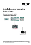
Run the program GT-20 Configurator (from Start menu \Programs \NAVISET). Turn on the
power supply of a device and connect it via USB cable to your computer. Having found the new
device, the operating system will suggest installing the driver.
Figure 1.1
Figure 1.2
Do not modify the default settings, i.e. leaving "automatic installation", click "Next".
Figure 1.3
4 User Manual “GT-20 v1.6 configurator”
Click the button "Ready" after the operating system installing the appropriate device drivers, for
a completion of master operation.
Figure 1.4
Further pass to the menu «Setup \Connection …» and in the dropdown list select Com port to
which the device is connected, and click "OK".
Figure 1.5
If the device is defined by a configurator, all buttons of a top panel will be active, and in status
bar there will be a message «Connected». If the device wasn't found, pass to the above described
menu and select other Com port.
The type of "TCP/IP" connection is used for remote device configuring.
If you select this type of connection, you see the "Server" window (Figure 1.6). In this window,
enter the available port of the system and press the "Start", after that the server will wait to
connect with a device. Further send to the device SMS COM5 command (see the passport) with
IP address and server port. After connection setting, menu buttons will become active.
Figure 1.6
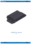
Visual appearance of the «GT-20 v1.3 Configurator» is shown in Figure 1.7.
5 User Manual “GT-20 v1.6 configurator”
1. GT-20 Configurator
2. Monitoring
3. Connection setting
4. Navigation setting
5. Inputs
6. Outputs
7. Security
8. Power supply
9. Peripheral
configuration
10. Auto informator
11. Event process
12. Voice message
13. Diagnostic file
14. Identification data
15. Device ID
16. IMEI
17. Firmware
18. Navigation
information'
19. Date and time
20. Latitude
21. Lengitude
22. Height
23. Speed, km/h
24. Heading, degree
25. Visible satellites
26. Horizontal delicacy
27. Coordinates
28. Jump
29. Acceleration
30. Turning angle
31. Distance traveled, m
32. Period of packet
33. The last written
packet
34. The last transferred
packet
35. Analog
inputs/outputs/state of
device
36. 1-8 inputs
37. 1-4 outputs
38. Temperature of
device
39. Level of GSM signal
40. U power
41. U battery
42. State
43. External periphery
44. 1-8 temperature 44. Fuel level sensor
45. 1 level
46. 1 temperature
47. 2 level
48. 2 temperature
49. Fuel level, %
50. Tachometer, r/sec
51. Coolant temperature,
degree
52. Motometer, h
53. Total distance, km
54. Total fuel
consumption, l
55. Total mass of vehicle,
kg
56. Axle Figure 1.7
6 User Manual “GT-20 v1.6 configurator”
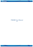
2. Buttons of a top panel
1. Run configuration
2. Open
3. Save
4. Read
5. Write
6. Delete track
7. Update SW
8. Reboot
Figure 2.1
The "File" menu contains the basic operations of configuration file:
- Run configuration by default;
- Open the configuration file;
- Save a configuration.
Points of this menu are duplicated on a panel below by buttons 1,2,3 respectively (a figure 2.1).
"Settings" menu. Menu selects the type of connection ("Connecting ..."), (Figure 2.2), and
turning on / off mode of diagnostics in real time (Figure 2.3).
Connecting…
Figure 2.2
Diagnostic
Figure 2.3
7 User Manual “GT-20 v1.6 configurator”
The following buttons are active in case of connection is set with a device.
Button "Read" (4) allows reading the current configuration of the device. Read data are
displayed in the appropriate fields of the program. Course reading is displayed in the window
(Figure 2.4).
Process execution
Reading the current
configuration… Figure 2.4
After configuration reading it will be reported of one of this message:
•
"Configuration is read" all data has been read;
•
“Not all data is read, update a configurator”. This message will appear if device software
version is newer, i.e. added new parameters which the configurator can't display.
•
“Try again”. This message will appear, if for whatever reason it was not possible to read a
configuration. Check connection with the device.
"Write" button (5) allows writing a configuration on the device (Figure 2.5).
Process execution
Writting the current
configuration… Figure 2.5
After the configuration writing it will be reported of one of this message:
•
“The device configuration is updated”. The operation of configuration writing is
successfully executed.
•
“The configuration isn't written, it is necessary to update a configurator”. The reason of
this message is insufficiency of data for configuring, i.e. the version of a device software is
newer with new parameters.
•
“Failed to update the configuration”. It was not possible to write a configuration for any
reason.
8 User Manual “GT-20 v1.6 configurator”
Button "Delete Track" (6). Used in the event if the structure of the package store was changed
in the internal memory (specified in the manual's part of firmware description) or just to remove
the accumulated packets. After clicking this button, it is appeared a window "Confirm"(Figure
2.6), which requires a password to complete the operation ("1234").
Confirmation
Enter a password Figure 2.6
Button “Update SW” (7). It allows using this configurator to update device software (figure
2.7).
To update device software click the button «…» and select “firmware_XXX.bin” file where
XXX indicates the software version.
If the selected file corresponds to required parameters, the button "Update program" will be
active, otherwise the message "The opened file is not a firmware file!!!" will appear.
To start the update, click the button “Update the program”. The device will reboot and start
programming. After programming completion the device will reboot and will return again to an
operating mode.
Update SW Figure 2.7
"Reboot" button (8). It is used for device reset without switching off to apply the made changes
in a configuration.
9 User Manual “GT-20 v1.6 configurator”
3. Status bar
Figure 3.1
Parking
The status bar is separated into four windows (figure 3.1).
Connected The window "1" displays information of the open, read or saved configuration file and can have
following values:
•
“default.fcg”. The configuration data is loaded by default.
•
“C:\My_conf.fcg”. The configuration is loaded from the My_conf.fcg file from the root
directory of the disk C:\ or if you are saving a file, the name of the saved file is displayed.
•
"Read from a device". Configuration was read from the device.
•
"Impossible to open". No access to open the file.
•
"Unable to save". The disc writing might be forbidden.
•
"File is not found, default.fcg is loaded”. During startup, the configurator tries to open the
last open or save file if the file is not found or access to it is forbidden, the configuration is
loaded by default.
The window "2" displays number of the current Com-port through which is using now.
Inscription "NC" indicates that the selected Com-port does not exist or cannot be opened. Go to
the menu "Settings \ Connection ..." and select the appropriate port.
The window "3" indicates device state: the device does not move and has a state of "parking" or
is moving and has a state of "movement." It can be used to configure the sensitivity of motion
sensor.
The window "4" displays connection mode information:
•
“Connected”. Connection with the device was set. Reception of information.
•
“V.1.0 loader mode”. Connection was set with the device loader, the loader version
information is provided here.
•
“The device isn't found”. It is displayed if the device doesn't respond to configurator
commands.
•
“Port Com setup …”. It is displayed when we are in the menu «Com port …».
10 User Manual “GT-20 v1.6 configurator”
4. Vertical menu
4.1. Monitoring
1. GT-20 Configurator
2. Monitoring
3. Connection setting
4. Navigation setting
5. Inputs
6. Outputs
7. Security
8. Power supply
9. Peripheral
configuration
10. Auto informator
11. Event process
12. Voice message
13. Diagnostic file
14. Identification data
15. Device ID
16. IMEI
17. Firmware
18. Navigation
information'
19. Date and time
20. Latitude
21. Lengitude
22. Height
23. Speed, km/h
24. Heading, degree
25. Visible satellites
26. Horizontal delicacy
27. Coordinates
28. Jump
29. Acceleration
30. Turning angle
31. Distance traveled, m
32. Period of packet
33. The last written
packet
34. The last transferred
packet
35. Analog
inputs/outputs/state of
device
36. 1-8 inputs
37. 1-4 outputs
38. Device temperature
39. Level of GSM signal
40. U power
41. U battery
42. State
43. External periphery
44. 1-8 temperature
45. Fuel level sensor
46. 1 level
47. 1 temperature
48. 2 level
49. 2 temperature
50. Fuel level, %
51. Tachometer, r/sec
52. Coolant temperature,
degree
53. Motometer, h
54. Total distance, km
55. Total fuel
consumption, l
56. Total mass of
vehicle, kg
57. Axle
58. Copy Figure 4.1
11 User Manual “GT-20 v1.6 configurator”
This window displays information of the device and a status of its main nodes:
• Identification data, such as number of the device, IMEI and software version;
• Navigation data (coordinates, height, speed, heading, quantity of satellites, etc.);
• The voltage of the analog inputs, external voltage, the internal battery;
• A state of outputs (0 – passive, 1 – active);
• Data of motion sensor axles;
• Internal temperature of the device;
• Level of GSM signal;
• GSM / GPRS registration State (0 - unregistered, 1 - registered, home network, 2 unregistered, the search of operator, 3 - registration is cancelled, 4 - unknown, 5 - registered,
roaming);
• Information of the external periphery (indication of temperature sensors, fuel level, the key
code of iButton, distance travelled, etc.).
12 User Manual “GT-20 v1.6 configurator”
4.2. Setting of connection
1. GT-20 Configurator
2. Monitoring
3. Connection setting
4. 1 connection
5. 2 connection
6. 3 connection
7. 4 connection
8. 5 connection
9. Navigation setting
10. Inputs
11. Outputs
12. Security
13. Power supply
14. Peripheral
configuration
15. Auto informator
16. Event process
17. Voice message
18. Diagnostic file
19. Device ID
20. Voice connection
parameters
21. Microphone gain
22. Dynamics gain
23. Number of tone after
auto answering
24. Voice menu volume,
auto informer
25. GPRS connection
parameters
26. IP server address
27. Server port
28. 1 SIM card
(operator)
29. Beeline
30. Other
31. Megaphone
32. MTS
33. Tele 2
34. # Server
35. Login
36. Password
37. 2 SIM card
(operator)
38. Beeline
39. Other
40. Megaphone
41. MTS
42. Tele 2
43. # Server
44. Login
45. Password
46. Auto update
47. Server address IP
48. Number of month
49. Server port
50. Radio silence mode
51. Time of log-on
52. Sleep mode after
transmission
53. Access password
54. Involve DTMF
55. Receive SMS of any
number
56. Confirmation of
SMS command
57. SMS in case of
balance lower
58. Forbid auto
switching of SIM cards
Figure 4.2
13 User Manual “GT-20 v1.6 configurator”
The setting of common connection parameters is completed in this window:
•
Device ID. Device peculiar number, assigned by a system;
•
Voice connection parameters;
•
GPRS connection parameters, where identified IP address and server port on which will send
data of device. Also you will need to specify which operator you used SIM cards, if there is
not your operator in list, select point “Other” and identify parameters on your own;
•
Auto update: IP address and server port with which the device will connect downloading
update in assigned date “Date” of each date;
“Radio silence mode”. Switching on present parameter is activated the Radio silence function:
the device connects at set intervals. Radio communications is active during fixing period of time
(10min), after that the device will in radio silence mode.
“Time of log-on” specifies time interval of log-on with a server.
“Sleep mode after transmission”. In case of active parameter the device will select
immediately radio silence mode after transmission of all stored data packets without waiting for
specified time interval.
“Access password”. It is a password allowing access to configuration via SMS or control via
DTMF;
“Confirmation of SMS command”. Confirmation of completed command will sent per each
correct accepted SMS command.
“SMS in case of balance lower”. Control a SIM card balance. When the balance is lower
identified level the SMS will sent to the first number of the list.
“Involve DTMF”. This parameter allows operation of DTMF decoder. With this enabled
parameter it is possible to work with voice menu and operate device.
“Receive SMS of any number”. Allows accept SMS of any telephone number.
“Forbid auto switching of SIM cards”. When the device has not GSM connection, it does not
switch to another SIM card, and continue operating of current SIM card until connection
reactivation. Switching to another SIM card is possible to do via command.
The setting of each 5 available connection parameters is completed in this window. Message is
sent if some of required source has an active move, separately to dial-up and SMS.
14 User Manual “GT-20 v1.6 configurator”
1. GT-20 Configurator
2. Monitoring
3. Connection setting
4. Connection 1-5
5. Navigation setting
6. Inputs
7. Outputs
8. Security
9. Power supply
10. Peripheral configuration
11. Auto informator
12. Event process
13. Voice message
14. Diagnostic file
15. Connection 1
16. Number
17. Message type
18. Received call
19. Received message
20. Dial-up
21. Quantity
22. Connection duration
23. Suffice to dial-in for
message delivery
24. Source
25. Input 1-8
26. Security
27. Monitoring
28. No external power
29. Accelerometer
30. SMS
31. Source
32. Input 1-8
33. Security
34. Monitoring
35. No external power
36. Accelerometer
37. Dial-up
38. Accept
39. Ignore
Figure 4.3
15 User Manual “GT-20 v1.6 configurator”
In the field “Number” enter a telephone number, to which will called or sent SMS. To number
“Connection 1” make a call pressing a button “Call manager” or send a service SMS, because of
that it is desirable to indicate number of your control center.
In the field “Message type” available to select one of the 4 variants:
•
“Dial-up”. Dial-up to specified number and if the parameter “Involve DTMF” is enabled
and SD card is installed with a files per each “source”, the respective message will be
displayed;
•
“Dial-up and SMS”. Above described is doubled sending respective SMS;
•
“SMS”. Send only SMS.
•
“SMS, if failing dial-up”. SMS is sending when the dial-up is failing.
In the field “Received call” available to select one of 4 variants:
•
“Accept”. After the specified number of tone in the menu “Connection setting” the device
will be automatic answered to a call. Answering to a call the audio interface is switched and
via it is available to listening;
•
“Accept and go to voice menu”. Additionally to above described, the voice menu is
switched on, on conditions that parameter “Involve DTMF” is active, via which you control
outputs of device or request current device state;
•
Change the security mode”.
Indentifying the number of caller the device select security
mode to the opposite one, i.e. if the device is disarmed, the device will be armed, and
without call answering will be declined it;
•
“END”. The received call will be declined.
The field “Received message” has 2 parameters to choice:
-
“Ignore”. Any received SMS will be ignored;
-
“Accept”. Receiving and SMS processing;
Parameter “Quantity” specifies quantity of attempts. The device will attempt to call to user. The
end of dial-up is answer to call.
Parameter “Duration of connect” specifies time of active connection;
-
“The length of message”. The connection will be ended automatically after pronunciation
respective message;
-
“Specify by user”. The time of connection ending is specified by user and is not depended
of pronounced message length.
16 User Manual “GT-20 v1.6 configurator”
Activated a parameter “Suffice to dial-in for message delivery”, the device is waiting an user
answer, after that it will decline the call. User answer is the fact that message is received. The
declining the call is occurring in not the chargeable call duration, which will not lead to a call
waste.
“Source” specify the operation (dial-up and/or SMS) selecting to an active mode. The operation
of inputs using for security is available only when the device is armed.
17 User Manual “GT-20 v1.6 configurator”
4.3. Navigation parameters
1. GT-20 Configurator
2. Monitoring
3. Connection setting
4. Navigation setting
5. Packet structure
6. Inputs
7. Outputs
8. Security
9. Power supply
10. Peripheral configuration
11. Auto informator
12. Event process
13. Voice message
14. Diagnostic file
15. During the parking
16. Select the writing per
event mode, min
17. Period of packet writing
during the parking, sec
18.Movement parameters
19. Accelerometer delicacy
20. Time of selecting to
"packing" mode after the
stopping, sec
21. Period of packet writing
during the movement, sec
22. Write the packet in each,
m, with the 20 km/h speed
23. Filtering on the straight
place. Deflection, degree
24. The drawing of corners
25. Min corner, degree
26. Min speed, km/h
27. Filtering of coordinates
during line change
28. Coordinate filtering
29. Max HDOP
30. Min speed, km/h
31. Max speed, km/h
32. Max jump of coordinates
per 1 sec, m
33. Max acceleration per 1
sec, m/sec2
Figure 4.4
18 User Manual “GT-20 v1.6 configurator”
This window is for:
•
The parameter setting of navigation data packet writing to memory of a device;
•
The parameter setting of coordinate filtering;
•
The choice of protocol and setting of a structure of transmit data packet.
The group “During the packing” has 2 parameters:
•
“Period of the packet writing during the packing” specifies the time interval, at the end
of which it will be operated the next packet writing during the vehicle parking;
•
“Select the writing per event mode”. If the parameter is active, the device suspends the
packet writing to memory. The next data packet will write in case of event, the source of
which will be movement sensor, the active mode of analog inputs, absent of external
voltage.
19 User Manual “GT-20 v1.6 configurator”
1. GT-20 Configurator
2. Monitoring
3. Connection setting
4. Navigation setting
5. Packet structure
6. Inputs
7. Outputs
8. Security
9. Power supply
10. Peripheral configuration
11. Auto informator
12. Event process
13. Voice message
14. Diagnostic file
15. Protocol
16. Packet structure
17. Device state
18. Voltage of source and
battery
19. Device temperature
20. State of inputs and
outputs
21. Inputs voltage 1-2
22. Inputs voltage 3-4
23. Inputs voltage 5-6
24. Inputs voltage 7-8
25. External temperature 1-4
26. External temperature 5-8
27. iButton key code
28. Data of frequency input
29. Fuel level Omnicomm
30. Data 1 of CAN bus
31. Data 2 of CAN bus
Figure 4.4.1
Group “Movement parameters”.
“Accelerometer delicacy” Dimensionless quantity, which specifies the level, in case of
exceeding it, the device will switch into a “movement” mode.
The level is setting experimentally. In a case of a false operation during a parking with an
operating engine of extreme vibration, the present parameter is necessary to increase.
“The time of switching into “parking” mode…” If during the indicated time the movement
sensor has passive state, the device is switching into “parking” mode.
“Period of writing the packet during the movement” specifies the time interval, with which
the data packet will record during the movement with the speed lower than 10 km/h.
“White the packet in each…”.If the speed is higher 10 km/h the interval of packet writing is
specified of travelled distance, which is in proportion to movement. For example, if the speed is
lower 20 km/h the parameter equals 30 m, so if the speed is higher 20 km/h and lower 40 km/h
the packet write per each 60 m, if the speed is of 40 km/h to 60 km/h – 90 m.
“Filtering on straight place”. If the present parameter is active, the additional filtering of
coordinates is conducted on the straight place, decline the traffic. In case of straight movement it
is controlled the deviation from the course, and if it is not higher specified value, the coordinates
is writing to device memory. If the filtering is switched on, the parameter “Write packet in
each…” is possible to low for more detail road drawing. The examples of writing track with
switching off filtering on the straight place (on the left) and with the switching on filtering (on
the right) are on the figure 4.5, 4.6, 4.7.
20 User Manual “GT-20 v1.6 configurator”
Group “The drawing of corners”.
“Minimum corner” is indicated the corner, in a case of lower which write a packet with
coordinates to device memory. The value of this corner must be chosen so that on the one side,
small maneuvers of vehicle in a straight place does not lead to the writing of data packet, and on
the side, the corner should not be large enough to be able to fix the turn.
“Minimum speed” defines a speed, if the value is higher it, the device is check a corner.
“Filtering of coordinates during line change” If the present parameter is enabled, the
additional filtering of corners is used via the algorithm. Fixing the moment of vehicle turn, the
coordinate analysis begins. If at the end of the analysis the direction of movement remains the
same (the car changed a line of road) or changed slightly (the turning angle didn't exceed 30
degrees), coordinates don't register in memory of the device. In case of switched on filtering,
“Minimum corner” can accept smaller value for more detail drawing of turn.
Group “Filtering of coordinates” If the filtering of coordinates is enabled, the analysis of saved
coordinates is made. If coordinates didn't pass the check to any parameter, last coordinates are
not saved in the device memory.
“Maximum HDOP” sets the maximum parameter value of horizontal delicacy.
"Minimum speed" is a minimum speed of movement.
"Maximum speed" is a maximum speed of movement.
“Maximum jump of coordinates” defines the maximum distance between two coordinates.
“Maximum acceleration” is an acceleration, coordinates are filtered if the value is higher it.
Group “Pre-setting”. This group allows selecting one of three settings.
Group "Protocol" allows selecting the data transmission protocol to the server.
Group “Packet structure”. Optional data which will be transferred to the server together with a
basic data are selected in this group. The basic (invariable) data include: number of the device,
package number, date and time, location, speed, direction, altitude, HDOP. The first packet
header (sent during connection of the server) contains information about: software version,
IMEI, device number.
21 User Manual “GT-20 v1.6 configurator”
Figure 4.5
Figure 4.6
Figure 4.7
22 User Manual “GT-20 v1.6 configurator”
4.4. Inputs
1. GT-20 Configurator
2. Monitoring
3. Connection setting
4. Navigation setting
5. Inputs
6. Input 1-8
7. Outputs
8. Security
9. Power supply
10. Peripheral configuration
11. Auto informator
12. Event process
13. Voice message
14. Diagnostic file
15. Input 1
16. Type of input
17. Active input level
18. Disturbing zone
19. High level
20. Current value
21. Low level
22. The length of the
averaging filter
23. Transition to an active
state(x100 msec)
24. Transition to the passive
state(х100 msec)
25. Output 1
26. Impulse duration
27. Pause
28. Repeat
29. No response
Figure 4.8
23 User Manual “GT-20 v1.6 configurator”
In this window setup of parameters is made for each of eight inputs.
In the field “Type of input” is defined an operation mode of the selected input:
•
"Not used". This input isn't used.
•
“Analog (36 V)”. An analog input with the range of 0 to 36 V
•
"Digital". The function is the same, as the previous one has.
•
“Analog 5 V”. An analog input with the range of 0 to 5 V
•
"Frequency". This input is used for signal frequency measurement.
•
"Call to a manager". The transition of the input to an active state leads to a set of the first
number in the list. Repeated transition drops a call.
•
"Arming / disarming." Transition of the input to the active state changes the security
mode, i.e. if the device is armed; the mode is change to the disarming, and vice versa.
•
"Ignition control". Connected to the ignition switch to control the on / off state of the
ignition. This feature is useful if you are using an analog fuel level sensor, the indication of
which is displayed during the ignition.
In the field “Active input level” is selected the active state of an input:
•
“Low or high”. The input is the active if input level is lower than lower level or higher
upper level, the intermediate state is passive.
•
“Low”. The active state of an input is in case of the level is lower than lower level. Any
other state is passive.
•
“Free”. The input is the active if input level is between the lower and upper levels, any
other is inactive.
•
“High”. If input level is higher than upper level, the state of an input is the active, any other
is passive.
•
“Low with a hysteresis”. The active status of an input is in case when the level is lower
than lower level, passive state is when higher upper level, a status of an input depends on the
movement direction in case when an interval between the lower and upper levels. If level is
increased of lower level to the upper level, the state is active. If it is on the contrary, the
state is inactive.
•
“High with a hysteresis”. It is the same as for the previous one, but it is on the contrary.
The upper and lower levels of operation are selected in the "Disturbing zone". Here the current
value of selected input voltage is also indicated. The indicator of a current state is token a blue
24 User Manual “GT-20 v1.6 configurator”
color if the input signal is in an inactive zone, "green" if it is in the free zone, "red" if it is in the
active zone.
“The length of the averaging filter” is the parameter, setting a time during which filtering of
input signal and can be set of 100 msec to 1000 msec.
In the group "Transition to an active state(x100 msec)" it is specified actions for each output
in transition of input to an active state.
In group «Transition to the passive state(х100 msec)» it is set action for each output in
transition of input to the passive state.
The choice of one of four options is available to each output:
•
«No response». The output doesn't react;
•
"Off". The output will be transferred to an inactive state;
•
"On". The output will be transferred to an active state;
•
"Impulse". The output state will be determined by the settings.
Parameters of the "impulse" output:
•
"Impulse duration" defines the time during which the output will be active. Time is
multiples of 100 msec;
•
"Pause" defines the time between repetitions of the impulse. Time is multiples of 100 msec;
•
"Repeat". Parameter specifies the number of impulse repetitions. A value=255 will result
of infinite repetition of impulse until the following state transition of an output.
«Frequency threshold» (it is active, if input type is frequency)field is used to process the
events. The exceeding of this threshold is considered that the frequency input is passed to the
active state.
25 User Manual “GT-20 v1.6 configurator”
4.5. Outputs
1. GT-20 Configurator
2. Monitoring
3. Connection setting
4. Navigation setting
5. Inputs
6. Outputs
7. Security
8. Power supply
9. Peripheral configuration
10. Auto informator
11. Event process
12. Voice message
13. Diagnostic file
14. Allow to control of
outputs via SMS
15. Allow to control of
outputs via DTMF
16. Active output state
17. Output 1
18. Output 2
19. Output 3
20. Output 4
21. The logic of output
operation controlling via
DTMF
22. Output 1
23. Impulse duration
24. Pause
25. Repeat
26. No response
27. Output 1 is a speed
sensor simulation
28. Impulses/km
Figure 4.9
26 User Manual “GT-20 v1.6 configurator”
This window is used for parameter setup of each output.
“Allow to control of outputs via SMS”. Switching on of this parameter allows to control of
outputs through SMS commands.
“Allow to control of outputs via DTMF”. Switching on of this parameter allows to control of
outputs via DTMF commands.
"Active output state" group defines the state (open or closed), which the output have when it is
activated.
In the group "The logic of output operation controlling via DTMF” it is specified actions for
each output in case of its activation. Parameter setup is described in section 4.4 "inputs".
“Output 1 is a speed sensor simulation”. Switching on of this function allows to receive
impulse sequence at output with duration which is proportional vehicle motion speed (on the
basis of the navigation solution). Using instead of the standard speed sensor. When using this
function attentively program the operation of outputs, i.e. in this case it is forbidden to use this
output in an event handler.
"Impulses/km". The parameter, setting number of pulses which shall appear at an output when
passing 1 km of a way. Calculated of the following formula:
Impulses / km = imp / rev (speed sensor) * rev / km (transmitting number)
Suppose the speed sensor produces 6 pulses in own revolution at the output, we get 6 imp / rev.
Transmitting number is the number of revolutions that makes the speed sensor when passing 1
km of the way, is determined of the vehicle construction, assume 1000 rev/ km.
By the data obtained: 6000 impulses / km.
If connecting to the tachograph it is used frequency divider (Level adapter), and knowing the
division ratio, you can immediately correct the value.
27 User Manual “GT-20 v1.6 configurator”
4.6. Security
1. GT-20 Configurator
2. Monitoring
3. Connection setting
4. Navigation setting
5. Inputs
6. Outputs
7. Security
8. Power supply
9. Peripheral configuration
10. Auto informatory
11. Event process
12. Voice message
13. Diagnostic file
14. Activate a security mode
15. Protected inputs
16. Arm / disarm
17. i-Button code
18. Time of disarmed, sec
19. Time of armed, sec
20. Restore inquiry time,
min
21. In case of alarm to make
pictures of the camcorder
22. Save to the carrier
23. Send to the server
24. Armed
25. Disarmed
26. Alarm
27. Time is multiple of
100 msec
28. Output 1
29. Impulse duration
30. Pause
31. Repeat
32. No response
Figure 4.10
28 User Manual “GT-20 v1.6 configurator”
Parameter of «Activate a security mode» allows or forbids function of device security.
In group «Protected inputs» are specified those inputs which must be controlled. The motion
sensor is monitored whenever the device is protected and the prohibition of its control is not
possible.
Group of "Arm / disarm."
For the control security it is possible to record up to five keys Touch Memory. In the field of the
table is entered the code, specified on a key in hexadecimal form, for example
«00000B57C5D0». The key code is entered automatically by touching the key to the contactor.
"Time of disarmed, sec" sets the time for the device disarming since the moment of fixing the
violation of any monitored inputs. Time does not apply to the motion sensor activating. In other
words, if during this time the device will not be disarmed, the penetration is fixed and alarm is
processed.
"Time of armed, sec" sets the time during which the device will not respond to changes of
inputs since the start arm (touching of a key).
"Restore inquiry time, min" sets the time after which since the moment of alarm fixing if the
last one wasn't disarmed, the device conducts re-arming.
“In case of alarm to make pictures of the camcorder”. If the external JPEG camcorder is
connected, in case of alarm, the device will receive continuously pictures from the camcorder,
with an interval in a second, and to save to internal SD card (“save to the carrier”) or to send
directly to the server (“send to the server”). The interval of receiving depends on the selected
image resolution and bit rate. Recording is stopped in case of alarm removal.
Tabs "Armed", "Disarmed" and "Alarm" set the action for each output. Arming is executed via
time of arming or immediately after receiving the command via SMS or from the server.
29 User Manual “GT-20 v1.6 configurator”
4.7. Power
1. GT-20 Configurator
2. Monitoring
3. Connection setting
4. Navigation setting
5. Inputs
6. Outputs
7. Security
8. Power supply
9. Peripheral configuration
10. Auto informatory
11. Event process
12. Voice message
13. Diagnostic file
14. External power supply
15. Output control in case of
voltage reduction lower …
16. Response time, sec
17. Output 1
18. Impulse duration
19. Pause
20. Repeat
21. No response
Figure 4.11
30 User Manual “GT-20 v1.6 configurator”
The device provides output control while reducing the external voltage below the threshold.
If the external voltage is below a predetermined threshold "Output control ..." and during the
time "Response time, sec" is not recovered, turn on output control with the specified
parameters. Parameter setup is described in section 4.4 Inputs.
31 User Manual “GT-20 v1.6 configurator”
4.8 Periphery setup
1. GT-20 Configurator
2. Monitoring
3. Connection setting
4. Navigation setting
5. Inputs
6. Outputs
7. Security
8. Power supply
9. Peripheral configuration
10. Auto informatory
11. Event process
12. Voice message
13. Diagnostic file
14. Operation mode
15. Combined
16. Involve the CAN
interface
17. Speed
18. Involve RS232/RS485 1
19. Speed
20. Type of the connected
device
21. Not defined
22. Involve RS232 2
23. Speed
24. Type of the connected
device
25. Not defined
26. Logfile writing to SDcard
27. NMEA transmission via
USB
28. Thresholds of external
temperature
29. Lower
30. Upper
31. Scanner of CAN bus
Figure 4.12
32 User Manual “GT-20 v1.6 configurator”
Group “Operation mode” is active if the GLONASS receiver is installed in the device. From
the drop down list the operation mode is selected:
•
"Combined". The current coordinates are determined, using data of GPS and GLONASS
satellites;
•
“Only GPS”. Data are used only of GPS satellites;
•
"Only GLONASS". Used data only of GLONASS satellites.
By default, the receiver solves the navigation problem in 3D mode. In case of insufficient
number of satellites the receiver can pass to a 2D mode if it is authorized “Allow 2D”.
“Involve the CAN interface”. Switching on of this parameter allows operation of the built-in
CAN interface for more information from the vehicle CAN bus. The CAN interface is used only
for data receiving. From the "Speed" list is selected data rate of CAN-interface, and can be set
of 100 Kbit / sec to 1Mbit/sec.
“Involve RS232/RS485 1”. Switching on of this parameter allows operation of the first digital
interface. This interface can work in the RS232 (CMOS) or RS485 mode. Switching is done
directly on the devices.
"Involve RS232 2." Enabling this parameter allows the operation of the second digital interface.
This interface can operate in RS232 (CMOS) or RS232 (UART) mode. Switching is done
directly on the device.
Field "Speed" set the data rate for the first and second interfaces. The speed can be selected
from the list or be entered manually.
The field “Type of the connected device” defines the device connected to the first or second
interface.
•
"Not defined". The additional device isn't connected to the interface.
•
"Fuel sensor Omnicomm (FS-E)" Digital fuel sensor is working to a protocol compatible
with the protocol Omnicomm. To receive and process the data from the sensor, you must
specify the address of the "Network address of 1 sensor" (Figure 4.13). The process of the
sensor calibration and address assignment are specified in a manual the appropriate sensor.
33 User Manual “GT-20 v1.6 configurator”
1. Involve RS232/RS485 1
2. Speed
3. Type of the connected device
4. Fuel sensor Omnicomm (FS-E)"
5. Network address of 1 sensor
6. Value of a complete tank 1
7. Edit the table
8. Value sum of the two sensors
Figure 4.13
The conversion data function from the sensor can be switching on in the device directly in liters
of calibration tables stored in device memory. If the parameter “Value of a complete tank 1” is
equal to zero, data from the sensor are deduced without conversion, i.e. directly a digital code
from the sensor. Value of a complete tank is entered in liter capacity.
The "Value sum of the two sensors" parameter is active in the case, if the two sensors are
connected to either RS232 or RS485, and the value of a full tank for each sensor is not equal to
zero. Enabling this parameter leads to the indications of the sensors are summed, and the amount
to be deduced as the indication of the first sensor.
To click the button “Edit the table” leads to opening of an additional window for editing of
calibration table data (a figure 4.14).
Filling process of the calibration table is the following:
1.
Read a device configuration ("Read");
2.
Value of a complete tank put equal to zero in order to display data directly from the
sensor;
3.
Write the configuration to the device ("Write");
4.
Open the calibration table and transfer to the “Monitoring" tab;
5.
Waste a tank, and, having waited for some time (10 seconds) during sensor indications
aren't stabilized yet, in line “Empty tank” of the calibration table, enter the indication
“Level 1” on the tab "Monitoring". Indications of the sensor can be also entered another
way: click the right mouse button on the selected cell and from the menu select point
“Insert the current value”;
34 User Manual “GT-20 v1.6 configurator”
6.
Further, assumed that value of a complete tank is equal to 100 liters and divided into 20
equal parts, receive a step of 5 liters "filling";
7.
Fill the tank with 5 liters of measured liquid. Having waited for some time (10 seconds),
enter the sensor indication into the next line of the calibration table ("1/20");
8.
Repeat step 7 until the tank won't be filled completely. For the correct operation of the
conversion algorithm, it is necessary to fill the calibration table completely;
9.
After the completion of table editing, click to button "Save" for saving of the made
changes;
10. In the "Value full tank 1" field enter the value of a full tank, in this example, 100 liters;
11. Save the table in the device memory by pressing the "Record" button.
1. Edit the table
2. Tank volume
3. Value 1
4. Value 2
5. Empty tank
6. ½ tank
7. Full tank
Figure 4.14
- "JPEG camcorder C328". Device is connected with the external JPEG camcorder C328 or
other compatible protocol camcorder. In the field "Resolution" is selected image resolution with
which it will save to the external carrier (a figure 4.15).
The button "View" allows receiving images from a camcorder with a resolution specified in the
"Resolution" to set its position.
- "Sensor (s) of fuel RS485”. Digital or fuel sensors with the RS485 interface are compatible
with the protocol Omnicomm (Figure 4.16). The setup process is described above in the
description of "Fuel sensor Omnicomm”.
35 User Manual “GT-20 v1.6 configurator”
Figure 4.15
1. Involve RS232/RS485 1
2. Speed
3. Type of the connected device
4. Fuel sensor RS485
5. Network address of 1 sensor
6. Value of a complete tank 1
7. Network address of 1 sensor
8. Value of a complete tank 1
9. Value sum of the two sensors
10. Edit the table
Figure 4.16
11. Involve RS232/RS485 1
12. Speed
13. Type of the connected device
14. JPEG camcorder C328
15. Resolution
16. Size, byte
17. View
- “Vehicle K-Line." The device is connected to the vehicle K-Line via the appropriate
transformer.
- “Radio module of 433 MHz”. The radio-frequency module is connected to the device.
“The record of Logfile to a SD card”. Switching on of this parameter allows record of the
diagnostic file to the external carrier. If the device is connected to a configurator, record of the
diagnostic file is suspended. Start diagnostic recording leads to a slight reduction in device
operation, therefore to use this function it is desirable only if it is necessary to carry out device
diagnostics in movement when connection of a configurator is impossible.
"Scanner of CAN bus." Enabling this parameter allows viewing incoming messages based on
CAN-bus vehicle.
36 User Manual “GT-20 v1.6 configurator”
Group "Thresholds of external temperature" is used when processing events from external
temperature sensors. If the threshold "Lower" is less than the threshold of "Upper", it is
considered that the source is switched to the active state. This state will be active as long as the
temperature will not become below the lower threshold, thus the state will change a mode to a
passive. Passive state will be active until the temperature transition through the upper level. If the
"lower" threshold is higher the "Upper" threshold and algorithm is the same, but while the
temperature transition of the upper level, it is considered that the source was passed to the
passive state.
"NMEA translation via USB”. If the parameter is enabled, NMEA messages coming from a
satellite receiver will be translated via the USB port.
37 User Manual “GT-20 v1.6 configurator”
4.9 Auto informer
1. GT-20 Configurator
2. Monitoring
3. Connection setting
4. Navigation setting
5. Inputs
6. Outputs
7. Security
8. Power supply
9. Peripheral configuration
10. Auto informatory
11. Event process
12. Voice message
13. Diagnostic file
14. Enable Autoinformer
15. Route file
16. List of geozone coordinates
17. Latitude
18. Longitude
19. Name of the reproduced file
20. Open
21. Read
22. Common quantity of
geozone
23. Save as a file
24. Write
Figure 4.17
38 User Manual “GT-20 v1.6 configurator”
The device has a function autoinformer. To use it, you must enable the parameter "Enable
Autoinformer". Autoinformer operation can lead to insignificant decline of device productivity.
Before using the autoinformer, you need to prepare audio files and edit the route files.
Remove the SD-card from the device and connect it via a card reader to your computer.
Create "Autoinfo" folder in the root of SD-card and place there the audio files with the
following parameters: wav, PCM, 12 kHz, mono, 8 bit. File name length with filename extension
must not exceed 29 characters. For example: Naberezhnaya.wav.
Start the Configurator to create or edit a file of a route “Marshrut.fai” and go to the tab
"Autoinformer".
Adding geozones coordinates (Figure 4.17) can be either manually or using the context menu
(Figure 4.18). Last one is a useful when recording a route following to it. To call a context menu
click right mouse button to the selected cell.
The following parameters are entered for each geozone:
•
Latitude;
•
Longitude;
•
Internal radius of an actuating zone (Rin);
•
External radius of an actuating zone (Rext);
•
A name of the reproduced file.
1. List of geozone coordinates
2. Open
3. Read
4. Latitude
5. Longitude
6. Name of the reproduced file
7. Insert the current coordinates
8. Select File
9. Add a line
10. Delete a line
11. Delete everything
12. Common quantity of geozone
13. Save as a file
14. Write
Figure 4.18
39 User Manual “GT-20 v1.6 configurator”
The context menu items:
•
"Insert the current coordinates" Insert the current location in the selected cell;
•
"Select File." Allows specifying the file to be displayed at the entrance to the current
geozone. Files should be indicated only those that are in the «Autoinfo» folder;
•
"Add a line" Add another line of geozone parameter. The maximum number of geozone is
limited to 100;
•
"Delete a line". Deletes the line for the selected cell
•
"Delete everything" Remove all parameters of geozones.
After entering the geozones parameters, save the route file "Save as a file" to the «Autoinfo»
folder. Saved it in another folder will cause of the autoinformer function will not work.
If the file of a route is created and it is necessary to edit it, use the "Open" button.
Further inset a SD card into the device and reboot it.
To edit the file of a route is possible without removing a SD-card from the device. For this
purpose set connection with the device, transfer to the tab "Autoinformer" and click the
"Read" button. The read file will be displayed in the appropriate table. After editing of route
parameters for saving the file click the "Write" button.
40 User Manual “GT-20 v1.6 configurator”
4.10 Event Processing
1. GT-20 Configurator
2. Monitoring
3. Connection setting
4. Navigation setting
5. Inputs
6. Outputs
7. Security
8. Power supply
9. Peripheral
configuration
10. Auto informatory
11. Event process
12. Voice message
13. Diagnostic file
14. Event Processing
15. Event 1
16. Source
17. State
18. No source
19. Transferred to active
20. Conditions
21. Logic
22. AND
23. OR
24. Accelerometer
25. Input 1-8
26. Condition state
27. Active
28. Passive
29. Accelerometer
30. Input 1-8
31. Action
32. Output 1 is on
33. Output 1 is off
34. Output 2 is on
35. Output 2 is off
36. Output 3 is on
37. Output 3 is off
38. Output 4 is on
39. Output 4 is off
40. Replay the message
41. Send SMS to number
1
42. Dial a number
43. Report to server
44. Operating time of
timers
45. Timer 1
46. Timer 2
47. Operating time of
timers, 100 msec
48. Timer 3
49. Timer 4
Figure 4.19
41 User Manual “GT-20 v1.6 configurator”
To switch on "Event Processing" allows the user of the available resources to organize their
own algorithm (s) of the device.
To the user it is available to program up to 20 events.
The event source is selected in the field "Source" from the available list.
In the "State" field the state is set to which the source is transferred or have:"Transferred to
passive," "Transferred to active", "Passive," "Active”.
"Logic" defines a mode of condition check.
"And" - action will be executed if all specified conditions are in the selected state.
"OR" - action will be executed, if at least one of the specified conditions is in the selected state.
The conditions are selected in the field "Conditions" in case of which the event source state is
checked. The condition can be not specified, and the operations are executed for a selected
source state.
Condition state (active / passive) is set in the "Condition state" field, which is checked when
processing the event, if the condition is selected.
In the field "Action" actions is specified which are necessary for executing. If "Replay the
message" is selected as action, it is necessary that there was an "event_X.wav" file on a SD card
in the "Voice" folder, where X is an event number of 1 to 20. Parameters of the sound file: wav,
PCM, 12 kHz, mono, 8 bits.
Algorithm of event processing is the following: if "Source" passed to "State" in case of
execution of selected "Conditions", it is carried out selected "Actions".
Action "Send SMS" and "Dial a number" tied to the events. For example, the events of 1 to 4
is attached the first number in the list, the events of 5 to 8 is attached the second number and etc.
«Operating time of timers». This field represents the time interval of the timer operation, if the
last are used in the event processing. The operation time of timer #1 and #2 is multiple of 1 sec,
and timers #3 and #4 is 100 msec.
When programming it is necessary to remember, that value of a source and a condition weren't
identical, otherwise the event cannot occur.
Consider the following example. The external indicator in the form of LED is connected the
output#2 via a current limiting resistor to the supply voltage. It is necessary that in case of object
movement indicator briefly flashed one time per second.
To implement this algorithm requires two events, "Event 1" is to activate the indicator and
"Event 2" is to turn off the indicator.
42 User Manual “GT-20 v1.6 configurator”
"Event 1" program to the following way:
•
As the "Source" select "Timer 1, sec";
•
"State":"Switch to the active";
•
"Logic" - any, as a condition is one: "The movement of the object";
•
"The condition state" - "The movement of the object" ticks off, i.e. in the active status;
•
As executed action select «Output 2 is on».
"Event 2" will have other parameters:
•
"Source": "Output 2";
•
"State”: "Active";
•
"Logic": any;
•
"Condition": It is possible not specified, or if the output is used in other events, the
"movement of the object";
•
"The condition state" - "The movement of an object" - "Action": "Output 2 is off."
43 User Manual “GT-20 v1.6 configurator”
4.11. Voice message
1. GT-20 Configurator
2. Monitoring
3. Connection setting
4. Navigation setting
5. Inputs
6. Outputs
7. Security
8. Power supply
9. Peripheral configuration
10. Auto informatory
11. Event process
12. Voice message
13. Diagnostic file
14. Welcome note
15. Enter a password
16. Incorrect password
17. Configuration menu
18. Output control is
forbidden
19. External voltage is
lower…
20. Armed
21. Disarmed
22. Movement sensor is
activated
23. Input 1-8 is activated
24. Output 1-4 is activated
25. Output 1-3 is
deactivated
Figure 4.20
44 User Manual “GT-20 v1.6 configurator”
This page allows working with the files which are storing on a SD card, without pulling out it
from the device.
In the group "Voice messages" it is bonded of audio file to a appropriate voice message. Select
a cell of voice message that you wish to bind a file, and then clicking the right mouse button to a
dialog box in which specify the audio file and click "Open".
In the appropriate cell there will be a way to the selected file.
The button “Save to the carrier” is used for copying of the selected audio files to device SD
card.
The button "Clear" is to clear all field of table.
The "The list of available" is displayed a list of files which is present on the carrier.
45 User Manual “GT-20 v1.6 configurator”
4.12. Diagnostics file
Diagnostic file
Date
Open
Figure 4.21
Group «Diagnostics file» allows reading the saved file of diagnostics. For this purpose in the
field "Date" select day for which it is necessary to receive the file of diagnostics and click the
"Read" button.
46