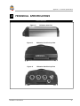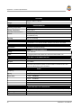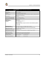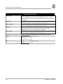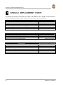
1
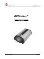
Software Rev. 3.34
OM-20000014 Rev. 1.0
TM
GPStation
User Manual
GPStation™ Products
NovAtel Inc.
GPStation™
User Manual
Publication Number:
OM-20000014
Revision Level:
1.0
96/10/22
GPStation, Narrow Correlator and Multipath Elimination Technology are trademarks of NovAtel Inc.
Dominion Automotive is a trademark of Dominion Automotive.
IBM and PC are registered trademarks of International Business Machines Corporation.
LEMO is a registered trademark of LEMO S.A.
Windows is a registered trademark of Microsoft Corporation.
Proprietary Notice
Information in this document is subject to change without notice and does not represent a commitment on the part of
NovAtel Inc. The software described in this document is furnished under a license agreement or non-disclosure
agreement. The software may be used or copied only in accordance with the terms of the agreement. It is against the law
to copy the software on any medium except as specifically allowed in the license or non-disclosure agreement.
No part of this manual may be reproduced or transmitted in any form or by any means, electronic or mechanical,
including photocopying and recording, for any purpose without the express written permission of a duly authorized
representative of NovAtel Inc.
The information contained within this manual is believed to be true and correct at the time of publication.
© 1996 NovAtel Inc. All rights reserved
Unpublished rights reserved under International copyright laws.
Printed in Canada on recycled paper. Recyclable.
ii
GPStation™ User Manual
Table of Contents
TABLE OF CONTENTS
FOREWORD
1 INTRODUCTION
viii
1
Features ......................................................................................................................................................................1
Connections and Indicators ........................................................................................................................................3
2 HARDWARE CONFIGURATION
4
Cable Connection Considerations...............................................................................................................................5
GPSAntenna Considerations ......................................................................................................................................5
Antenna Cable Considerations ...................................................................................................................................6
Power Supply Considerations.....................................................................................................................................6
Input Power Cables ....................................................................................................................................................6
Serial Data Cables ......................................................................................................................................................7
I/O Strobe Port Cable ...............................................................................................................................................10
User-Supplied Radio or Modem...............................................................................................................................11
Oven-Controlled Crystal Oscillator (OCXO) ...........................................................................................................11
3 OPERATION
12
OCXO Warm-Up .....................................................................................................................................................12
Communications with the GPStation........................................................................................................................12
Serial Port Default Settings ...........................................................................................................................12
Communicating Using a Remote Terminal ...................................................................................................13
Communicating Using a Personal Computer .................................................................................................13
Getting Started..........................................................................................................................................................13
Boot-Up .........................................................................................................................................................14
DOS...............................................................................................................................................................15
Windows 3.1 or Higher..................................................................................................................................15
4 FIRMWARE UPGRADES & UPDATES
17
Upgrading Using the $AUTH Command .................................................................................................................17
Updating Using the “Loader” Utility........................................................................................................................18
Downloading Firmware Files ........................................................................................................................18
Using the Loader Utility ................................................................................................................................19
APPENDIX A TECHNICAL SPECIFICATIONS
21
APPENDIX B GPStation REPLACEMENT PARTS
26
We Would Like To Hear From You...
27
GPStation™ User Manual
iii
Table of Contents
TABLES
1
2
3
4
Feature Summary - GPStation Models.............................................................................................................................2
Straight Cable Pin Configurations ....................................................................................................................................8
Null Modem Cable Pin Configurations ............................................................................................................................9
I/O Port Pin-out Description...........................................................................................................................................10
FIGURES
1
2
3
4
5
6
7
8
9
10
11
12
13
14
Photograph of GPStation................................................................................................................................................1
GPStation Front End-cap................................................................................................................................................3
GPStation Rear End-cap.................................................................................................................................................3
Typical GPStation Installation Configuration ................................................................................................................4
Power Cables..................................................................................................................................................................7
Straight Serial Port Cable ...............................................................................................................................................8
Null Modem Serial Port Cable .......................................................................................................................................9
I/O Port Cable ..............................................................................................................................................................10
Typical Operational Configuration...............................................................................................................................12
Sample WinSat Screen .................................................................................................................................................13
Main screen of LOADER program ..............................................................................................................................19
GPStation Side View....................................................................................................................................................21
GPStation Front End-cap View ....................................................................................................................................21
GPStation Rear End-cap View .....................................................................................................................................21
iv
GPStation™ User Manual
Warranty
WARRANTY POLICY
NovAtel Inc. warrants that its Global Positioning System (GPS) products are free from defects in materials and
workmanship, subject to the conditions set forth below, for the following periods of time:
GPStation Series
GPSAntenna Series
Cables and Accessories
Software Support
One (1) Year
One (1) Year
Ninety (90) Days
One (1) Year
Date of sale shall mean the date of the invoice to the original customer for the product. NovAtel’s responsibility
respecting this warranty is limited solely to product repair at an authorized NovAtel location only. Determination of
repair will be made by NovAtel personnel or by technical personnel expressly authorized by NovAtel for this purpose.
THE FOREGOING WARRANTIES DO NOT EXTEND TO (I) NONCONFORMITIES, DEFECTS OR ERRORS IN
THE PRODUCTS DUE TO ACCIDENT, ABUSE, MISUSE OR NEGLIGENT USE OF THE PRODUCTS OR USE IN
OTHER THAN A NORMAL AND CUSTOMARY MANNER, ENVIRONMENTAL CONDITIONS NOT
CONFORMING TO NOVATEL’S SPECIFICATIONS, OR FAILURE TO FOLLOW PRESCRIBED INSTALLATION,
OPERATING AND MAINTENANCE PROCEDURES, (II) DEFECTS, ERRORS OR NONCONFORMITIES IN THE
PRODUCTS DUE TO MODIFICATIONS, ALTERATIONS, ADDITIONS OR CHANGES NOT MADE IN
ACCORDANCE WITH NOVATEL’S SPECIFICATIONS OR AUTHORIZED BY NOVATEL, (III) NORMAL WEAR
AND TEAR, (IV) DAMAGE CAUSED BY FORCE OF NATURE OR ACT OF ANY THIRD PERSON, (V) SHIPPING
DAMAGE; OR (VI) SERVICE OR REPAIR OF PRODUCT BY THE DEALER WITHOUT PRIOR WRITTEN
CONSENT FROM NOVATEL.
IN ADDITION, THE FOREGOING WARRANTIES SHALL NOT APPLY TO PRODUCTS DESIGNATED BY
NOVATEL AS BETA SITE TEST SAMPLES, EXPERIMENTAL, DEVELOPMENTAL, PREPRODUCTION,
SAMPLE, INCOMPLETE OR OUT OF SPECIFICATION PRODUCTS OR TO RETURNED PRODUCTS IF THE
ORIGINAL IDENTIFICATION MARKS HAVE BEEN REMOVED OR ALTERED.
THE WARRANTIES AND REMEDIES ARE EXCLUSIVE AND ALL OTHER WARRANTIES, EXPRESS OR
IMPLIED, WRITTEN OR ORAL, INCLUDING THE IMPLIED WARRANTIES OF MERCHANTABILITY OR
FITNESS FOR ANY PARTICULAR PURPOSE ARE EXCLUDED.
NOVATEL SHALL NOT BE LIABLE FOR ANY LOSS, DAMAGE OR EXPENSE ARISING DIRECTLY OR
INDIRECTLY OUT OF THE PURCHASE, INSTALLATION, OPERATION, USE OR LICENSING OR PRODUCTS
OR SERVICES. IN NO EVENT SHALL NOVATEL BE LIABLE FOR SPECIAL, INDIRECT, INCIDENTAL OR
CONSEQUENTIAL DAMAGES OF ANY KIND OR NATURE DUE TO ANY CAUSE.
There are no user serviceable parts in the GPStation and no maintenance is required. When the status code indicates that
a unit is faulty, replace with another unit and return the faulty unit to NovAtel Inc.
You must obtain a RETURN MATERIAL AUTHORIZATION (RMA) number by calling GPS Customer Service
at 1-800-280-2242 or 403-295-4900 before shipping any product to NovAtel or Dealer.
Once you have obtained an RMA number, you will be advised of proper shipping procedures to return any defective
product. When returning any product to NovAtel, please return all original diskettes along with the defective product in
the original packaging to avoid electrostatic and/or shipping damage.
ANY ATTEMPT TO OPEN THE GPStation CASE WILL IMPAIR THE WATER-RESISTANT QUALITIES
OF THE ENCLOSURE, AND VOID THE WARRANTY.
GPStation™ User Manual
v
Customer Service
CUSTOMER SERVICE
If you require customer service, please provide the following information along with a detailed description of the problem
when you call or write:
Serial No._______________________________________ Model No. _________________________________________
Software Release No. _____________________________
Date Purchased:__________________________________
Purchased from: ____________________________________________________________________________________
User name: _____________________________________ Title: ______________________________________________
Company: _________________________________________________________________________________________
Address:___________________________________________________________________________________________
City:___________________________________________ Prov/State: _________________________________________
Zip/Postal Code: _________________________________ Country: ___________________________________________
Phone #:________________________________________ Fax #: _____________________________________________
E-mail:_________________________________________
GPStation interface: Computer type: _______________________________ Operating Shell: ______________________
Other interface used: _________________________________________________________________________________
Please provide a complete description of any problems you may be experiencing, or the nature of your inquiry (attach
additional sheets if needed):
__________________________________________________________________________________________________
__________________________________________________________________________________________________
__________________________________________________________________________________________________
__________________________________________________________________________________________________
__________________________________________________________________________________________________
You may photocopy and fax this page, call, or mail the above information to the address listed below.
For customer support, contact the NOVATEL GPS Hotline at 1-800-280-2242 or 403-295-4900; send a fax to
403-295-4901; send e-mail to [email protected], visit our web site at www.novatel.ca; or write to:
NovAtel Inc.
GPS Customer Service
1120 - 68th Avenue N.E.
Calgary, Alberta, Canada
T2E 8S5
vi
GPStation™ User Manual
Notices
FCC NOTICE
FCC approval (Class A digital device) is pending.
CAUTION !
Handle with Care
Use Anti-Static Precautions
GPStation™ User Manual
vii
Foreword
FOREWORD
Scope
This manual provides sufficient information for the initial set-up and operation of the GPStation; its focus is on the user’s
perspective for integration, evaluation, and operation purposes. It is beyond the scope of this manual to provide service
or repair details. Please contact your NovAtel Customer Service Centre for any customer-service problems or inquiries.
The following documents have been supplied to provide you additional valuable reference information:
•
GPSCard Command Descriptions Manual - a description of the GPSCard commands and logs available to the user.
It is written in generic form so as to accommodate all models of GPSCard-based receivers.
•
WinSat Graphical Interface Program User Manual - a description of the user-interface software included with all
GPSCard receivers.
Other supplementary manuals may be included to accommodate special models and software features with unique
functionality. These documents are to be considered as companion manuals, and should be kept together to allow easy
reference from one to the other. For example, a reference in this manual to a command or logging activity may require
you to consult the GPSCard Command Descriptions Manual for a deeper understanding of the full contents and usage of
that particular command or log.
Prerequisites
The GPStation requires the addition of peripheral equipment before it can become fully functional. Section 2, Hardware
Configuration, provides information concerning installation requirements and considerations.
The GPSCard, mounted within the GPStation, utilizes a comprehensive user interface command structure which requires
communications through its serial communications ports (COM1 and COM2). To utilize the built-in command structure
to its fullest potential, it is recommended that some time be taken to review and become familiar with Sections 2 through
6 of the Command Descriptions Manual before the initial operation.
viii
GPStation™ User Manual
1 – Introduction
1
INTRODUCTION
The NovAtel GPStation is a high-performance, reliable GPS receiver with a built-in high-stability oscillator. As such, it
is intended for use as a differential GPS base station as well as other demanding positioning applications.
The GPStation is intended to be used with the following NovAtel accessories:
•
•
•
Model 501 GPSAntenna
Model A030 Choke-ring Ground Plane - to reduce the effects of multipath reception
Model C005, C015, or C030 (5, 15 or 30 m length) coaxial cable - to connect the GPSAntenna to the GPStation
After the addition of these accessories, together with user-supplied data communications equipment and a power supply,
the GPStation will be ready for use.
FEATURES
The GPStation includes the following features:
•
•
•
•
•
•
GPS receiver
•
rugged, water and dust-resistant enclosure (see Figure 1)
•
modified NovAtel OEM2 GPSCard with GPStation software
•
two serial communication ports and a strobe port
high-stability Oven-Controlled Crystal Oscillator (OCXO)
one straight and one null-modem serial-data cable
one I/O strobe cable
an AC/DC converter, and power cables
NovAtel WinSat graphical user interface software and user manual
Figure 1
Photograph of GPStation
The GPStation features a 12-channel, parallel tracking, C/A (Coarse Acquisition) code GPS receiver operating on the L1
(1575.42 MHz) frequency. Each dedicated channel independently tracks the code and carrier phase of a GPS satellite in
view. The GPStation incorporates NovAtel’s patented Narrow Correlator technology that achieves pseudorange accuracy
with near P-code performance and provides the industry’s most robust resistance against errors introduced by multipath
signals. The improved pseudorange accuracy reduces the time required for ambiguity resolution when carrier phase
measurements are being made and substantially improves the receiver’s performance in differential mode. The customGPStation™ User Manual
1
1 – Introduction
built, proprietary correlator chip combined with a high performance, 32-bit CPU is capable of generating satellite code
and carrier phase data at a rate of up to 20 times per second, and computing up to 10 position solutions per second among the highest rates found in the industry. Exceptional acquisition and re-acquisition times are also a standard feature
of this high-performance receiver.
The GPStation is available in two models whose features are summarized in Table 1:
Table 1
Feature Summary - GPStation Models
General
12 parallel tracking channels
Narrow Correlator spacing
2 configurable RS-232C serial data ports
Fast re-acquisition
Field-programmable for firmware upgrades
Multipath Elimination Technology
High-stability OCXO
GPSTN
GPSTNM
✓
✓
✓
✓
✓
N/A
✓
✓
✓
✓
✓
✓
✓
✓
✓
✓
✓
✓
✓
✓
✓
✓
✓
✓
✓
✓
✓
✓
✓
✓
✓
✓
✓
✓
✓
✓
✓
✓
✓
✓
✓
✓
✓
✓
✓
✓
✓
✓
✓
✓
✓
✓
✓
✓
✓
✓
✓
✓
✓
✓
✓
✓
✓
✓
✓
✓
Data Logging Rates
Computed Data: Position, speed, direction, & clock offset @ 10 / sec
Measured Data: Pseudorange & carrier phase @ 20 / sec
Output Data Log Formats
NovAtel-proprietary ASCII and binary
NMEA 0183 Ver. 2.0
RINEX Ver. 2
RTCM SC-104 Rel. 2.0 Types: 1, 3, 9, 16, 59N
RTCA/DO-217 Types: 1
Positioning Modes of Operation
Single point
Waypoint navigation
Differential (using pseudorange corrections)
Receiver Control
Clock drift correction
Ability to save receiver configuration settings, & almanac
Reset (hardware or firmware activated)
Serial port control
Datum (table or user-definable)
Magnetic variation correction
Undulation (table or user-definable)
Satellite elevation cutoff control
Position, height & velocity constraints
Satellite lockout control
Satellite health control
Strobes
Mark input (position & time)
1 PPS timing output (for GPS time synchronization)
Measurements strobe
User-defined frequency output pulse train
Solution status output
The high-stability Oven-Controlled Crystal Oscillator (OCXO) ensures highly accurate pseudorange and carrier
measurements for DGPS, real-time kinematic (with an RT-20 enabled remote station), and post-processing applications.
2
GPStation™ User Manual
1 – Introduction
The enclosure measures 320 mm x 130 mm x 60 mm, weighs 1.5 kg and is constructed of extruded aluminum. It is sealed
by two end-caps which are connected by five mounting screws.
NOTE 1: The unit is sealed to provide protection against adverse environmental conditions. Any attempt to open the
enclosure will impair its water-resistant qualities and void the warranty.
NOTE 2: Although the GPStation has a rugged enclosure, it is neither intended for kinematic applications nor designed
to withstand high levels of vibration or shock. Any of these conditions would impair the stability of the OCXO.
NovAtel leads the industry in state-of-the-art GPS receiver design. We believe our GPStation product line will meet your
high expectations. Future products and enhancements from NovAtel are aimed at helping you to maintain that level of
satisfaction.
CONNECTIONS AND INDICATORS
The GPStation features front and rear end-caps (Figures 2 & 3), each with appropriate indicator lights and connectors.
The front end-cap indicator light glows red if power is present, then green when a valid position is computed.
Figure 2
GPStation Front End-cap
GPStation
On the rear end-cap there are connections for the I/O strobe signals, COM1 & COM2 serial ports, power input, and RF
input from the GPSAntenna. There is a LED above each serial port connector. If a LED glows red, data is being
received by the GPStation on that port, while if a LED glows green, data is being transmitted by the GPStation on that
port.
Figure 3
GPStation™ User Manual
GPStation Rear End-cap
3
2 – Hardware Configuration
2
HARDWARE CONFIGURATION
Installing the GPStation is a straightforward process. As shown in Figure 4, a minimum configuration is established with
the following set-up:
•
•
•
•
Set up the GPSAntenna and optional choke-ring ground plane
Route and connect coaxial cable between the GPSAntenna and GPStation.
Connect an RS232 communication interface to one of the serial ports of the GPStation. The supplied null
modem cables are intended for RS232 communications only.
Connect the output of the power adapter to the input power jack of the GPStation.
Figure 4
Typical GPStation Installation Configuration
GPStation
GPSAntenna Models 501, 511 or 521
(pictured: GPSAntenna Model 501 &
Choke-ring Ground Plane Model A030)
RF cable
Automotive
cigarette-lighter
adapter
Power cable
I/O strobes cable
AC/DC converter
Straight serial data cable
(male connector attaches to
user-supplied modem or
radio transmitter)
Null-modem serial data
cable (female connector
attaches to user-supplied
operator interface)
Operator interface
4
GPStation™ User Manual
2 – Hardware Configuration
CABLE CONNECTION CONSIDERATIONS
The connectors that are used to mate the cables to the GPStation have a locking mechanism which requires careful
insertion and removal. Observe the following when handling the cables.
•
•
•
•
To insert a cable, make certain you are using the appropriate cable for the port
– the COM1/COM2 serial port cable has a different connector (10 pin) than
the I/O cable (8 pin).
Line up the red dot on the connector shell with the red index mark on the
socket.
Insert the connector until it seats with a click; it is now locked in place.
To remove a cable, grasp the connector by the knurled ring and pull (see
illustration). DO NOT PULL DIRECTLY ON THE CABLE.
GPSAntenna CONSIDERATIONS
The purpose of the antenna is to convert the electromagnetic waves transmitted by the GPS satellites at the L1 frequency
(1575.42 MHz) into electrical signals.
The GPStation has been designed for use with the NovAtel Model 501 GPSAntenna as a means of ensuring the highestprecision positioning accuracy. The Model 501 uses low-profile microstrip technology and include band-pass filtering
and an LNA which is powered directly by the GPStation. It offers exceptional phase-center stability as well as a
significant measure of immunity against multipath interference. To reduce multipath reception even further, the
GPSAntenna can be mounted on an optional NovAtel Choke Ring Ground Plane (refer to the GPSAntenna Model 501
User Manual for more details).
The 501’s low-noise amplifier (LNA) boosts the power of the incoming signals by 23 dB to compensate for cable losses;
if the losses are greater than this, excessive signal degradation will occur and the GPStation may not be able to meet its
performance specifications. The 501 has an environmentally-sealed radome.
NOTE:
antenna.
The performance specifications of the GPStation are guaranteed only when it is used with a NovAtel-supplied
When installing the antenna, select a location with a clear view of the sky to the horizon so that each satellite above the
horizon can be tracked without obstruction. The location should also be one that minimizes the effect of multipath (for a
discussion on multipath, please refer to the chapter on “Multipath Elimination Technology” in the GPSCard Command
Descriptions Manual). Ensure that the antenna is securely mounted on a stable structure that will not sway or topple.
GPStation™ User Manual
5
2 – Hardware Configuration
ANTENNA CABLE CONSIDERATIONS
The RF cable that you require will depend on the specific antenna selected for use in your system and the distance
between the antenna and the GPStation. NovAtel offers high-quality coaxial cable in the following lengths: 5 m (Model
C005), 15 m (Model C015), and 30 m (Model C030); these come with a TNC male connector at each end. Should your
application require the use of cable longer than 30 m, contact your NovAtel GPS Customer Service representative and
request Application Note APN-003, “Extended-Length Antenna Cable Runs” before you proceed.
The GPSAntenna Model 501 can compensate for up to 23 dB of cable loss; if this limit is exceeded, excessive signal
degradation will occur and the GPStation may not be able to meet its performance specifications.
While there may be other coaxial cables on the market which might also serve the purpose, please note that the
performance specifications of the GPStation are guaranteed only when it is used with NovAtel-supplied RF cables.
NOTE: The coaxial cable should be connected to the antenna and GPStation before system power is turned on. If the
antenna cable becomes disconnected from the antenna or GPStation, remove power from the GPStation before
reconnecting the cable; this will prevent the GPStation’s antenna current-limiting circuit from unnecessarily activating.
POWER SUPPLY CONSIDERATIONS
The GPStation incorporates a DC-to-DC power converter providing filtering, automatic reset circuit protection, and
voltage regulation. It accepts a single input voltage between the range of +10 to +36 V DC. The power input is reverse
polarity protected. Refer to the Power Requirements section of Appendix A for further information.
The DC output of the autoranging AC/DC converter will meet the GPStation’s requirements for an input of 110 - 220 V
AC.
NOTE: Operating the GPStation outside the specified input voltage range may result in damage to the GPStation,
and/or unreliable data.
INPUT POWER CABLES
As shown in Figure 5, there are three power cables supplied with the GPStation:
1.
2.
3.
4-pin LEMO socket connector to 2-pole plug connector (NovAtel p/n 01016380)
2-pole socket connector to cigarette-lighter plug with built-in 2 amp fuse (NovAtel p/n 01016446)
2-pole socket connector to AC/DC converter, and AC power cord (NovAtel p/n 01016447)
These cables allow you to power the GPStation from either an AC source or an automotive DC source. For field
replacement of either the LEMO connector or the 2-pole connectors, please consult Appendix B for a list of the
manufacturers’ part numbers.
6
GPStation™ User Manual
2 – Hardware Configuration
Figure 5
1 (-)
Red marker at top
of connector
Power Cables
4 (-)
Cigarette-lighter
plug
2 - pole connector socket
2 (+)
3 (+)
2 - pole connector plug
LEMO
4 - pin socket
BROWN
ORANGE
RED
BLACK
1
2
3
4
+
+
-
GND
+10 to +36 V DC
+10 to +36 V DC
GND
2 - pole connector socket
4 conductor wire
AC/DC
converter
AC socket
AC plug
SERIAL DATA CABLES
Two serial data cables are supplied to connect the GPStation to a PC or modem. They are described as follows:
•
straight cable: 10-pin LEMO plug to 9-pin D-connector (DE9P plug); see Figure 6 & Table 2. This is used to
connect the GPStation to a modem or radio transmitter to propagate the differential corrections. Its NovAtel part
number is 01016383.
•
null-modem cable: 10-pin LEMO plug to 9-pin D-connector (DE9S socket); see Figure 7 & Table 3. This is used to
connect the GPStation to a serial (RS232) communication port on a terminal or computer. Its NovAtel part number
is 01016329.
The 10-pin plug on each cable can be plugged into either the COM1 or COM2 port on the GPStation.
For field replacement of the LEMO connector, please consult Appendix B for the manufacturer’s part number.
GPStation™ User Manual
7
2 – Hardware Configuration
Figure 6
Straight Serial Port Cable
Red marker at top
of connector
S1
9
8
S5
1
7
2
6
3
5
4
10
S6
S9
DE9P (male)
LEMO 10 pin plug
1
BROWN 1
BLACK
2
RED
3
ORANGE 4
YELLOW 5
GREEN 6
BLUE
7
VIOLET 8
GRAY
9
WHITE 10
2
3
4
5
6
7
8
9
10-conductor cable
Table 2
LEMO Pin No.
Pin 1
Pin 2
RS232 Signal
DCD
RXD
Wire Color Code
Brown
Black
DE9P Pin No.
Pin 1
Pin 2
Pin 3
TXD
Red
Pin 3
Pin 4
DTR
Orange
Pin 4
Pin 5
GND
Yellow
Pin 5
Pin 6
DSR
Green
Pin 6
Pin 7
RTS
Blue
Pin 7
Pin 8
CTS
Violet
Pin 8
Pin 9
NULL
Gray
Pin 9
Pin 10
8
Straight Cable Pin Configurations
White (Not used)
GPStation™ User Manual
2 – Hardware Configuration
Figure 7
Null Modem Serial Port Cable
Red marker at top
of connector
S5
9
8
S1
1
7
2
6
3
5
4
10
S9
S6
DE9S (female)
LEMO 10 pin plug
BROWN
RED
BLACK
GREEN
YELLOW
ORANGE
VIOLET
BLUE
GRAY
BROWN 1
2
BLACK
3
RED
ORANGE 4
YELLOW 5
GREEN 6
7
BLUE
VIOLET 8
9
GRAY
WHITE 10
1
2
3
4
5
6
7
8
9
10-conductor cable
Table 3
LEMO Pin No.
Pin 1
Pin 2
Null Modem Cable Pin Configurations
RS232 Signal
DCD
RXD
Wire Color Code
Brown
Black
DE9S Pin No.
Pin 4
Pin 3
Pin 3
TXD
Red
Pin 2
Pin 4
DTR
Orange
Pin 6
Pin 5
GND
Yellow
Pin 5
Pin 6
DSR
Green
Pin 4
Pin 7
RTS
Blue
Pin 8
Pin 8
CTS
Violet
Pin 7
Pin 9
NULL
Gray
Pin 9
White (Not used)
Pin 1 jumpered to Pin 6
Pin 10
GPStation™ User Manual
9
2 – Hardware Configuration
I/O STROBE PORT CABLE
The I/O strobe lines can be accessed by inserting the 8-pin LEMO connector of the I/O strobe port cable (NovAtel p/n
01016330) into the I/O port. Figure 8 and Table 4 contain wiring and pin-out information on this cable. The other end of
the cable is provided without a connector so that the user can provide an application-specific one; the jacket insulation is
cut away slightly from the end but the insulation on each wire is intact. The Input/Output Strobes section of Appendix A
contains a specification of each I/O strobe signal.
For field replacement of the LEMO connector, please consult Appendix B for the manufacturer’s part number.
Figure 8
I/O Port Cable
Red marker at top
of connector
8
7
1
2
6
3
5
4
LEMO 8-pin socket
BROWN
BLACK
RED
ORANGE
YELLOW
GREEN
BLUE
WHITE
1
2
3
4
5
6
7
8
VARF
1PPS
MKO
MKI
STATUS
GND
GND
GND
8 conductor wire
Table 4
LEMO Pin
Number
Pin 1
Pin 2
Pin 3
Pin 4
Pin 5
Pin 6
Pin 7
Pin 8
I/O Port Pin-out Description
Pin Description
VARF, variable frequency
1 PPS, one pulse per second
MSR, measure output
MKI, mark input
STATUS , valid solutions available
GND
GND
GND
Wire Color Code
Brown
Black
Red
Orange
Yellow
Green
Blue
White
Note that the STATUS line is used to toggle the valid-position LED on the front end-cap between red (power on) and
green (valid position).
10
GPStation™ User Manual
2 – Hardware Configuration
USER-SUPPLIED RADIO OR MODEM
When using the GPStation as a DGPS base station, it needs to be connected to user-supplied equipment that will
propagate the differential corrections to remote stations. Whether this equipment is a modem that sends the corrections
over telecommunication channels, or radio transmitting equipment that sends the corrections through an atmospheric
path, the only requirement is that it have an RS-232C serial data interface through which data can be exchanged with
either the COM1 or COM2 port of the GPStation.
NOTE:
When using radio transmitting equipment, please ensure that you comply with all applicable government
regulations (such as obtaining a license, and obtaining approval before operating a transmitter or setting up an antenna
near an airport).
When using a radio transmitter to disseminate the differential corrections, keep in mind that its maximum “line-of-sight”
range will primarily be influenced by the effective radiated power (determined, in turn, by the transmitter’s power output,
the gain of its antenna, and any losses in the transmitting subsystem), the height of the transmitting antenna, and the
height of the receiving antenna. The documentation supplied with the radio equipment should contain the information
needed to design an effective radio network.
OVEN-CONTROLLED CRYSTAL OSCILLATOR (OCXO)
The built-in, high-stability OCXO enables the GPStation to generate highly accurate differential corrections. The OCXO
section of Appendix A summarizes the operating characteristics of this oscillator. It is important to remember that the
OCXO requires 3-5 minutes after power-up to stabilize its temperature; differential corrections should not be sent until
after this stabilization has occurred. The GPStation power requirements increase when the OCXO heater switches on; see
the Power Requirements section of Appendix A.
NOTE:
The accuracy of the OCXO is impaired by vibration and shock, so it is essential that the GPStation be at rest
on a stable and secure surface during operation. The GPStation has rubber feet in order to reduce the effect of vibration.
GPStation™ User Manual
11
3 – Operation
3
OPERATION
Before using the GPStation for the first time, ensure that you have set up your system as recommended in Section 2. The
following instructions are based on a configuration such as that shown in Figure 9. It is assumed that a personal
computer is used during the initial operation and testing for greater ease and versatility. Furthermore, it should be
understood that communication between the GPStation and a computer is achieved by virtue of the GPS firmware which
resides within the GPStation.
Figure 9
Typical Operational Configuration
User interface
GPSAntenna
Models
501, 511 or 521
Data
GPStation enclosure
COM 1
Power to LNA
RF signal
GPSCard
& OCXO
COM 2
Data
Power Converter
Power
Radio
or
Modem
Power source
+10 to +36 V DC
OCXO WARM-UP
Each time the GPStation is powered up, allow 3-5 minutes for temperature stabilization of the OCXO to occur before
beginning base-station transmissions. This will ensure that the differential corrections sent to remote stations are of the
highest accuracy.
COMMUNICATIONS WITH THE GPSTATION
Communication with the GPStation is straightforward, and consists of issuing commands through the COM1 or COM2
port from an external serial communications device. This could be either a terminal or an IBM-compatible PC that is
directly connected to a GPStation serial port using a null-modem cable. Further information on the GPSCard commands
and logs can be found in the GPSCard Command Descriptions Manual.
SERIAL PORT DEFAULT SETTINGS
For communication to occur, both the GPStation and the PC or terminal have to be configured properly. The GPStation’s
default port settings are as follows:
•
RS232C protocol, 9600 bits per second, no parity, 8 data bits, 1 stop bit, no handshaking, echo off
Changing the default settings requires the use of the COMn command, which is described in the GPSCard Command
Descriptions Manual. It is recommended that the user become thoroughly familiar with the commands and logs to ensure
maximum utilization of the GPStation’s capabilities.
12
GPStation™ User Manual
3 – Operation
NOTE: Although the GPStation can operate at bit rates as low as 300 bps, this may not always be desirable. For
example, if several data logs are active (i.e. a significant amount of information needs to be transmitted every second) but
the bit rate is set too low, data will overflow the serial port buffers and cause an error condition in the receiver status.
COMMUNICATING USING A REMOTE TERMINAL
One method of communicating with the GPStation is through a remote terminal. The GPStation has been pre-wired to
allow proper RS232C interface with a data terminal. To communicate with the terminal, the GPStation only requires the
RX, TX, and GND lines to be used; handshaking is not required, although it can optionally be used. Ensure that the
terminal’s communications set-up matches the GPStation RS232C protocol.
COMMUNICATING USING A PERSONAL COMPUTER
An IBM-compatible PC can be set up to emulate a remote terminal as well as provide the added flexibility of creating
multiple-command batch files and data logging storage files. Any standard communications software package that
emulates a terminal can be used to establish bi-directional communications with the GPStation.
One can create command batch files using any text editor; these can then be directed to the serial port that is connected to
the GPStation using a communications software package. This is discussed in greater detail later in this chapter.
GETTING STARTED
Included with your GPStation are NovAtel’s WinSat and Convert programs, together with a user manual for them.
WinSat is a Windows-based graphical user interface which allows one to interact with the GPStation without struggling
with communications protocol or writing special software. WinSat automatically recognizes the model of GPStation
being used and adjusts the displays accordingly. Figure 10 shows a sample WinSat screen. Convert is a Windows-based
utility that allows you to convert between file formats, and strips unwanted records for data file compilation.
Figure 10
GPStation™ User Manual
Sample WinSat Screen
13
3 – Operation
WinSat is provided to facilitate the user’s interaction with the GPStation. However, it certainly is possible to
communicate with the GPStation through DOS or a Windows-based communications program; this is discussed in greater
detail later in this section.
BOOT-UP
The GPStation’s software resides in read-only memory. As such, the unit “self-boots” upon power-up and undergoes a
complete self-test. If an error condition is detected during a self-test, the self-test status would change; this self-test status
information can be viewed in the RGEA/B/C and RVSA/B data output logs (please refer to the GPSCard Command
Descriptions Manual). If a persistent error develops, please contact NovAtel Customer Service.
When the GPStation is first powered up, no activity information is transmitted from the COM ports except for the port
prompt; the screen on an external data communications device will display one of these two messages:
Com1> if connected to COM1 port,
or
Com2> if connected to COM2 port
Either prompt indicates that the GPStation is ready and waiting for command input.
Commands are typed at the interfacing terminal’s keyboard, and sent after pressing the terminal’s Return or Enter key.
NOTE: Most valid commands do not echo a response to a command input; the indication that they have been accepted
is a return of the port prompt from the GPStation. VERSION, HELP and ? are the only commands that provide a data
response other than the port prompt.
Example:
An example of no echo response to an input command is the FIX HEIGHT command. It can be entered as follows:
COM2>fix height 550 [Return]
COM2>
The above example illustrates command input to the GPStation COM 2 port which sets the GPStation antenna height as
fixed to 550 m above sea level and causes position solutions to be constrained as 2D with height fixed. However, your
only confirmation that the command was actually accepted is the return of the COM2> prompt.
If a command is incorrectly entered, the GPStation will respond with “Invalid Command Name” (or a more detailed error
message) followed by the port prompt.
After initial boot up, you may find the following logs useful for observing the GPStation activities. While WinSat is the
easiest way to do this, you can also use DOS or a Windows-based communications program; examples of both are
provided below.
•
•
•
•
•
•
•
•
14
Use the RCCA log to list the default command settings. After the GPStation has been operational for a while, the
RCCA log will be useful for indicating status of all current command settings. Displaying the RCCA log after a
RESET will show the saved configuration (see the description of the SAVECONFIG command for more
information).
Use the ETSA log to monitor the channel tracking status.
Use the SATA log to observe the satellite specific data.
Use the POSA log to observe the current computed position solutions.
Use the DOPA log to monitor the dilution of precision of the current satellite constellation.
Use the RVSA log to monitor the receiver status.
Use the HELP command to list all available commands.
Use the HELP LOG command to list all available logs.
GPStation™ User Manual
3 – Operation
Refer to the Command Descriptions Manual for procedures and explanations related to data logging.
DOS
One way to initiate multiple commands and logging from the GPStation is to create DOS boot-up command files relating
to specific functions. This will save time when you want to duplicate test situations and minimize set-up time. Any
convenient text editor can be used to create command text files.
Example:
For this example, consider a situation where a PC’s appropriately-configured COM1 port is connected to the GPStation’s
COM1 port, and where a remote terminal is connected to the GPStation’s COM2 port. The PC user wishes to monitor
the GPStation’s activity; the following command file could be used to do this.
1.
Open a text editor on the PC and type in the following command sequences:
log
log
log
log
log
com2
com2
com2
com2
com2
sata
etsa
rvsa
posa
dopa
ontime
ontime
ontime
ontime
ontime
15
15
60 5
15
15
2.
Save this with a convenient file name (e.g. C:\GPS\BOOT1.TXT) and exit the text editor.
3.
Use the DOS copy command to direct the contents of the BOOT1.TXT file to the PC’s COM1 port:
C:\GPS>copy boot1.txt com1
1 files(s) copied
C:\GPS>
4.
The GPStation is now initialized with the contents of the BOOT1.TXT command file, and logging is directed from
the GPStation’s COM2 port to the remote terminal.
WINDOWS 3.1 OR HIGHER
As any text editor or communications program can be used for these purposes, the use of Windows 95 is described only
as an illustration. The following example shows how the Windows 95 accessory programs Notepad and HyperTerminal
can be used to create a hypothetical waypoint navigation boot-file on a PC, and send it to the GPStation. It is assumed
that the PC’s serial port COM1 is connected to the GPStation’s COM1 port, and that a remote terminal is connected to
the GPStation’s COM2 port.
Example:
1.
Open Notepad and type in the following command text:
setnav 51.111 -114.039 51.555 -114.666 0 start stop
magvar -21
log com1 posa ontime 15
log com1 spha ontime 15
log com1 nava ontime 15
log com2 gprmb ontime 15 5
log com2 gpvtg ontime 15 5
log com2 rcca ontime 60
2.
Save this with a convenient file name (e.g. C:\GPS\BOOTNAV1.TXT) and exit Notepad.
GPStation™ User Manual
15
3 – Operation
3.
Ensure that the HyperTerminal settings are correctly set up to agree with the GPStation communications protocol;
these settings can be saved (e.g. C:\GPS\OEMSETUP.HT) for use in future sessions. You may wish to use XON /
XOFF handshaking to prevent loss of data.
4.
From the Transfer menu, use the Send text file selection to locate this file to be sent to the GPStation. Once you
double-click on the file or select Open, then HyperTerminal will send the file to the GPStation.
The above example initializes the GPStation with origin and destination waypoint coordinates and sets the magnetic
variation correction to -21 degrees. The POSA, SPHA, and NAVA logs have been set to output from the GPStation
COM1 port at intervals of once every 15 seconds, whereas the GPRMB and GPVTG NMEA logs have been set to be
logged out of the GPStation COM2 port at intervals of 15 seconds and offset by five seconds. The RCCA log has been
set to output every 60 seconds from the GPStation COM2 port.
16
GPStation™ User Manual
4 - Firmware Upgrades & Updates
4
FIRMWARE UPGRADES & UPDATES
The GPStation stores its program firmware in non-volatile memory, which allows the user to perform firmware upgrades
and updates without having to return the GPStation to the factory. New firmware can be downloaded to the GPStation
through a serial port, and the unit will immediately be ready for operation at a higher level of performance.
The first step in upgrading your receiver is to contact NovAtel GPS Customer Service via any of the methods described in
the Customer Service section at the beginning of this manual. A Customer Service Representative will assist you in
selecting the best upgrade option that suits your specific GPS needs.
When you call, be sure to have available your GPStation model number, serial number, and program revision level. This
information is printed on the original shipping box as well as on the back side of the GPStation itself. You can also verify
the information by issuing the VERSION command at the port prompt.
After establishing which new model/revision level would best suit your needs, and having described the terms and
conditions, Customer Service will issue to you an authorization code (auth-code). The auth-code is required to unlock
the new features according to your authorized upgrade/update model type.
There are two procedures to choose from, depending on the type of upgrade/update you require:
1.
If you are upgrading to a higher performance model at the same firmware revision level (e.g. upgrading from a
GPSTN Rev. 3.42, to a GPSTNM Rev. 3.42), you can use the $AUTH special command.
2.
If you are updating to a higher firmware revision level of the same model (e.g. updating a GPSTN Rev. 3.42 to a
higher revision level of the same model), you will need to download new program firmware to the GPStation using
the Loader utility program. As the Loader and update programs are generally provided in a compressed file format,
you will also be given a file decompression password. The Loader and update files can be found on NovAtel’s BBS
or FTP site, or can be sent to you on floppy disk or by e-mail.
Customer Service will provide you with all the information which you require to update or upgrade your receiver.
UPGRADING USING THE $AUTH COMMAND
The $AUTH command is a special input command which authorizes the enabling or unlocking of the various model
features. Use this command when upgrading to a higher performance GPStation model available within the same
revision level as your current model (e.g., upgrading from a GPSTN Rev. 3.42, to a GPSTNM Rev. 3.42). This
command will only function in conjunction with an auth-code assigned by GPS Customer Service.
The upgrade can be performed directly from WinSat’s Command Line Screen, or from any other communications
program. The procedure is as follows:
1) Power-up the GPStation and establish communications over a serial port (see Section 3, Operation)
2) Issue the VERSION command to verify the current firmware model number, revision level, and serial number.
3) Issue the $AUTH command, followed by the auth-code and model type. The syntax is as follows:
Syntax:
$auth auth-code
GPStation™ User Manual
17
4 - Firmware Upgrades & Updates
where
$auth
auth-code
is a special command which allows program model upgrades
is the upgrade authorization code, expressed as hhhh,hhhh,hhhh,hhhh,hhhh,model# where the
h characters are an ASCII hexadecimal code, and the model# would be ASCII text
Example:
$auth 17cb,29af,3d74,01ec,fd34,gpstnm
Once the $AUTH command has been executed, the GPStation will reboot itself. Issuing the VERSION command will
confirm the new upgrade model type and version number.
UPDATING USING THE “LOADER” UTILITY
Loader is required (instead of the $AUTH command) when updating previously released firmware with a newer version
of program and model firmware (e.g., updating a GPSTN Rev. 3.42 to a higher revision level of the same model).
Loader is a DOS utility program designed to facilitate program and model updates. Once Loader is installed and running,
it will allow you to select a host PC serial port, bit rate, directory path, and file name of the new program firmware to be
downloaded to the GPStation.
DOWNLOADING FIRMWARE FILES
To proceed with your program update, you must first acquire the latest firmware revision. You will need a file with a
name such as OEMXYZ.EXE (where XYZ is the firmware revision level). This file is available from NovAtel’s GPS
Bulletin Board (403-295-4206) or FTP site (ftp.novatel.ca), or via e-mail ([email protected]). If downloading is not
possible, the file can be mailed to you on floppy disk.
You will need at least 1 MB of available space on your hard drive. For convenience, you may wish to copy this file to a
GPS sub-directory (e.g., C:\GPS\LOADER).
The file is available in a compressed format with password protection; Customer Service will provide you with the
required password. After copying the file to your computer, it must be decompressed. The syntax for decompression is
as follows:
Syntax:
[filename] -s[password]
where
filename
-s
password
is the name of the compressed file (but not including the .EXE extension)
is the password command switch
is the password required to allow decompression
Example:
oem342 -s12345678
18
GPStation™ User Manual
4 - Firmware Upgrades & Updates
The self-extracting archive will then generate the following files:
•
•
•
LOADER.EXE
LOADER.TXT
XYZ.BIN
Loader utility program
Instructions on how to use the Loader utility
Firmware version update file, where XYZ = program version level (e.g. 342.BIN)
USING THE LOADER UTILITY
The Loader utility can operate from any DOS directory or drive on your PC. The program is comprised of three parts:
Program Card (authorization procedure), Setup (communications configuration) and Terminal (terminal emulator). The
main screen is shown in Figure 11.
Figure 11
Main screen of LOADER program
If you are running Loader for the first time, be sure to access the Setup menu (step 3 below) before proceeding to
Program Card (step 4 below); otherwise, you can go directly from step 2 below to step 4. The procedure is as follows:
1.
Turn off power to the GPStation.
2.
Start the Loader program.
3.
From the main menu screen, select Setup to configure the serial port over which communication will occur
(default: COM1) , and the data transfer rates for both programming (default: 115 200 bits per second) and terminal
emulation (default: 9600 bps). To minimize the time required, select the highest serial bit rate your PC can reliably
support. Loader will verify and save your selections in a file named LOADER.SET, and return to the main menu
screen.
4. From the main screen, select Program Card.
5.
Select the disk drive (e.g., A, B, C, D) in which the update file (e.g. 342.BIN) is located. Select the path where the
update program file is located (e.g., C:\GPS\LOADER); the directory from which you started Loader is the default
path. Select the required update file (e.g. 342.BIN).
6.
At the prompt, enter your update auth-code (e.g. 17b2,32df,6ba0,92b5,e5b9,gpstnm).
GPStation™ User Manual
19
4 - Firmware Upgrades & Updates
7.
When prompted by the program, turn on power to the GPStation. Loader will automatically establish
communications with the GPStation. The time required to transfer the new program data will depend on the bit rate
which was selected earlier.
8.
When the download is complete, use the terminal emulator in Loader (select Terminal), or any other one, to issue
the VERSION command; this will verify your new program version number. When using the terminal emulator in
Loader, a prompt does not initially appear; you need to enter the command first, which then produces a response,
after which a prompt will appear.
9.
Exit Loader (select Quit).
This completes the procedure required for field-updating a GPStation.
20
GPStation™ User Manual
Appendix A - Technical Specifications
A
TECHNICAL SPECIFICATIONS
PHOTOGRAPHS
Figure 12
Figure 13
GPStation Side View
GPStation Front End-cap View
GPStation
Figure 14
GPStation™ User Manual
GPStation Rear End-cap View
21
Appendix A - Technical Specifications
PHYSICAL
Size:
320 mm x 130 mm x 60 mm
Weight:
1.5 kg
ENVIRONMENTAL
Operating Temperature
-25° C to +40° C
Storage Temperature
-40°C to +85°C
Resistance Characteristics
Dust tight, water tight
Altitude
5000 m (may operate above this altitude in a controlled environment, however, is
not certified as such)
Humidity
95% non-condensing
VIBRATION
The GPStation is not rated for vibration because of its effect on the OCXO.
ACCELERATION (DYNAMICS)
Acceleration
4 g maximum (sustained tracking)
POWER REQUIREMENTS
Voltage
+10 to +36 V DC
Power
11 W (typical) when OCXO heater off; 16 W when OCXO heater is on
RF INPUT / LNA POWER OUTPUT
Connector on GPStation
TNC female
RF Input
1575.42 MHz
Power Output to LNA
4.0 - 5.0 V DC @ 10 - 25 mA (current limit 35 mA). Note: if the antenna draws
current above or below these limits, the self-test status code will be set to zero.
Refer to the RVSA log for more information.
OCXO
Frequency
20.473 MHz
Ageing
5 x 10
Phase Noise
-10
1 Hz:
-7
per day, 1 x 10 per year
-80 dBc/Hz
10 Hz: -110 dBc/Hz
100 Hz: -140 dBc/Hz
1 kHz: -150 dBc/Hz
10 kHz: -155 dBc/Hz
INPUT/OUTPUT DATA INTERFACE
Dual RS-232C Serial
Bit rates: 300, 1200, 4800, 9600, 19200, 57600, 115200 bps (9600 bps default)
Signals supported
TX, RX, RTS, CTS, DTR, DSR, DCD
Electrical format
EIA RS232C Standard
22
GPStation™ User Manual
Appendix A - Technical Specifications
PERFORMANCE (Subject To GPS System Characteristics)
Frequency
1575.42 MHz (L1)
Codes tracked
C/A code (SPS)
Channels
12 independent tracking channels
Time to First Fix
< 70 s typical (cold start: no initial time, almanac or position required) assuming
stabilized OCXO temperature
Re-acquisition
3 s typical
Computed Data Update Rate
≤ 10 solutions per second
Measured Data Update Rate
≤ 20 data records per second
Pseudorange
Position Accuracy
Stand-alone:
(real-time)
15 m CEP (SA off), GDOP < 2
40 m CEP (SA on)
Differential using two R-option Performance Series GPSCards (GDOP<4):
< 0.75 m CEP
< 1.00 m SEP
Pseudorange Code
Measurement Accuracy
10 cm RMS, 3 minutes, no multipath, C/No > 44 dB-Hz
30 cm RMS in multipath environment with choke ring ground plane
Single Channel Carrier
Phase Measurement Accuracy
2 mm RMS, C/No > 44 dB-Hz
Loop BW = 15 Hz
Differential Channel Carrier
Phase Measurement Accuracy
0.5 mm RMS, 1 second smoothed, no multipath, C/No > 44 dB-Hz
Height Measurements
≤ 18,288 m (due to export licensing restrictions)
Velocity Measurements
≤ 515 m/s (due to export licensing restrictions)
Velocity Accuracy
0.05 m/s (SA off);
0.20 m/s (SA on)
Time Accuracy (relative)
50 ns (SA off);
250 ns (SA on)
GPStation™ User Manual
23
Appendix A - Technical Specifications
INPUT/OUTPUT STROBES
VARF Output
A programmable variable frequency output ranging from 156 Hz - 10.23 MHz
(refer to FREQUENCY_OUT command), with pulse width = 49 ns. This is a
normally high, active low pulse. The time between pulses may vary by as much
as 49 ns jitter.
PPS Output
A one-pulse-per-second time synchronization output. This is a normally high,
active low pulse (200 µs) where the falling edge is the reference.
Measure Output
20 pulses-per-second output, normally high, active low where the pulse width is
200 µs. The falling edge is the receiver measurement strobe.
Mark Input
An input mark (negative pulse > 55 ns), time tags output log data to the time of
the falling edge of the mark input pulse (refer to LOG command syntax ONMARK). This line is TTL or contact-closure compatible.
Status Output
Indicates a valid GPS position solution is available. A high level indicates a valid
solution or that the FIX POSITION command has been set.
Table 4 contains I/O port pin-out information. The electrical specifications of the strobe signals are as follows:
Output
Input
24
Voltage:
Standard TTL levels
Sink Current:
64 mA
Source Current:
15 mA
Voltage:
Standard TTL levels
Current:
≤ 5 mA
GPStation™ User Manual
Appendix B - GPStation Replacement Parts
B
GPStation REPLACEMENT PARTS
The following lists describe the replacement parts available for the GPStation system. Should you require assistance or
need to order additional components, please contact your NovAtel Customer Service representative.
Part Description
NovAtel Part Number
I/O strobes cable
01016330
Null-modem serial data cable
01016329
Power cable #1 (LEMO 4-pin socket to 2-pole plug)
01016380
Power cable #2 (2-pole socket to cigarette-lighter plug)
01016446
Power cable #3 (2-pole socket to AC/DC converter, c/w AC power cord)
01016447
Straight serial data cable
01016383
Part Description
4-pin socket connector on power cable
8-pin socket connector on I/O cable
LEMO Part Number
FGJ.0B.304.CNLD52Z
FGL.1K.308.CLLC45Z
10-pin plug connector on both serial data cables
FGG.1K.310.CLAC55Z
Part Description
Dominion Automotive Part Number
2-pole plug connector: male connector body
DA 762158
2-pole plug connector: male plug
DA 762150
2-pole plug connector: grommet
DA 762152
2-pole socket connector: female connector body
DA 762159
2-pole socket connector: female socket
DA 762151
2-pole socket connector: grommet
DA 762152
26
GPStation™ User Manual
We Would Like To Hear From You...
NovAtel Inc. is committed to providing you, our valued customer, with quality products and customer
service.
We would appreciate hearing from you. Please take a few moments to think about the questions below,
then respond through any of the methods listed in the Customer Service section at the beginning of this
manual. At NovAtel, we value your input.
•
Which products have you purchased from NovAtel GPS?
Receivers:
GPStation ____________
GPSCard:
OEM Series __________
PC Series _______
GPSAntenna: _______________
Accessories: _____________________ Other: _________________________________________
•
Are you satisfied with the performance of these products:
Yes
No
Yes
No
Please explain.
•
Are you satisfied with the level of customer service provided?
Please explain.
•
What influenced you to purchase NovAtel GPS products?
•
Do you have any comments concerning this User Manual?
•
Are there any new features or products that you would like to see from NovAtel GPS?
•
Do you have any other comments or suggestions?
Your name_______________________________Company___________________________________
Address/phone number ________________________________________________________________
___________________________________________________________________________________
GPStation™ User Manual
27
NOTES
28
GPStation™ User Manual
NOTES
GPStation™ User Manual
29
NovAtel Inc.
6732 – 8th Street N.E.
Calgary, Alberta, Canada T2E 8M4
GPS Hotline: (403) 295-4900
GPS Fax: (403) 295-4901
E-mail: [email protected]
Web site: http://www.novatel.ca
OM-20000014 – Rev. 1.0
96/10/22
Recyclable
Printed in Canada
on recycled paper
Software Rev. 3.34