1
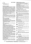
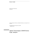
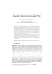
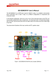
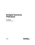
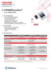
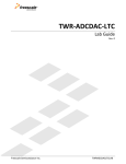
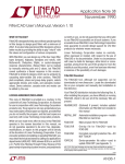
DEMO MANUAL DC1840B DC1682B and DC1680A LTC4270/LTC4271 12-Port PSE with Digital Isolation Description Demonstration kit DC1840B is a 12-port Type 2 power sourcing equipment (PSE) composed of a DC1682B daughter card and DC1680A mother board. The kit is used for evaluation of the LTC4270B and LTC4271 PSE chipset. Up to 12 powered devices (PDs) can be connected and powered from this system using a single power supply. A DC590B is connected to the DC1840B for I2C interfacing with QuikEval™. This demonstration manual provides a Quick Start Procedure, a DC1682 overview, a DC1680 overview, schematics, and layout printouts. Other available supporting documents for the DC1840 are the LTC4270/LTC4271 Layout Guide and the LTC4271 PSE Demo Software Users Manual. Design files for this circuit board are available at http://www.linear.com/demo L, LT, LTC, LTM, Linear Technology and the Linear logo are registered trademarks and QuikEval is a trademark of Linear Technology Corporation. All other trademarks are the property of their respective owners. Board Photo dc1840bfc 1 DEMO MANUAL DC1840B Quick Start Procedure Demonstration kit DC1840B includes the DC1682 daughter card and DC1680 mother board. The kit is set up for evaluating the LTC4270/LTC4271. Follow the procedure below and refer to Figures 1 through 4 for proper equipment setup. 4.On the DC1680, connect a supply with the positive rail to POS and negative rail to NEG (Figure 3). Use a power supply capable of sourcing the maximum load expected (12 ports × 850mA ≥ 10.2A). Ramp the supply up to 55V. 1.On the DC1682 set AUTO jumper JP1 to HI (Figure 1) to enable AUTO pin mode. 5.Connect up to 12 PDs to the DC1680, J4 (Figure 3). 2.On the DC1682 set MID jumper JP2 to LO (Figure 1) to disable midspan mode. 3. Align pin 1 of the 34-pin male connector on the DC1682 with pin 1 of the 34-pin female connector on the DC1680 (Figure 2). Pin 12 is polarized to assist with the alignment. Carefully push the DC1682 straight down until the two 34-pin connectors are flush with each other. 2 6. The DC590 is optionally connected to the DC1680 connector J5 with a 14-pin ribbon cable (Figure 3). A GUI for the LTC4270/LTC4271 is brought up by QuikEval for I2C interfacing from a PC (Figure 4). dc1840bfc DEMO MANUAL DC1840B Quick Start Procedure Figure 1. DC1682 Backside. Setting AUTO and MID Jumpers Figure 2. Inserting the DC1682 into J1 of the DC1680 dc1840bfc 3 DEMO MANUAL DC1840B quick start procedure Figure 3. DC1840 Basic Setup Figure 4. System Setup with the DC590, DC1680, DC1682 and 55V Power Supply 4 dc1840bfc DEMO MANUAL DC1840B Demonstration Circuit 1682B Operation 12-Port PSE Daughter Card with Digital Isolation Demonstration circuit 1682B (Figure 5) features the LTC4270/LTC4271 chipset on a compact daughter card with digital isolation. The LTC4270/LTC4271 chipset is a 12-port power sourcing equipment (PSE) controller designed for use in IEEE 802.3at Type 1 and Type 2 (high power) compliant Power over Ethernet (PoE) systems. A transformer isolated communication protocol replaces expensive opto-couplers and complex isolated 3.3V supply resulting in significant BOM cost savings. The LTC4270/ LTC4271 chipset delivers lowest-in-industry heat dissipation by utilizing low RON external MOSFETs and 0.25Ω sense resistors, eliminating the need for expensive heat sinks. Advanced power management features in the LTC4270/ LTC4271 chipset include: per port 12-bit current monitoring ADCs, DAC programmable current limit, and versatile quick shutdown of preselected ports. PD discovery uses a proprietary dual mode 4-point detection mechanism ensuring excellent immunity from false PD detection. Midspan PSEs are supported with 2-event classification and a two second backoff timer. The LTC4270/LTC4271 includes an I2C serial interface operable up to 1MHz. The DC1682B demonstrates proper LTC4270/LTC4271 board layout that is approximately the height and width of a 2 × 6 RJ45 connector. The compact layout is made possible by the small package size of key components. The LTC4270 is in a 7mm × 8mm QFN, while the LTC4271 is in a 4mm × 4mm QFN. Each port has a FDMC3612 MOSFET in a 3mm × 3mm power33 package. The daughter card inserts in the DC1680B mother board through J1, a polarized 34-pin connector. Isolated 3.3V and logic control signals are brought in on this connector. Also connected at J1 is the PoE VEE supply from the mother board and 12 PSE controlled outputs. Figure 5. DC1682A 12-Port PSE Daughter Card with Digital Isolation Features the LTC4270 and LTC4271 dc1840bfc 5 DEMO MANUAL DC1840B Demonstration Circuit 1682B Operation Board Layout Isolation and Power Supplies Proper board layout is crucial for proper LTC4270/LTC4271 chipset operation, robustness, and accuracy. When laying out, pay attention to parts placement, Kelvin sensing, power paths, and copper fill. It is imperative to follow the LTC4270/LTC4271 Layout Guide document when laying out the board. The LTC4270/LTC4271 chipset provides communication across an isolation barrier through a data transformer (Figure 6). This eliminates the need for expensive optocouplers. All digital pins reside on the digital ground reference and are isolated from the analog PoE supply. A 3.3V supply for VDD and an isolated VEE supply are connected to the DC1682B through the 34-pin connector. 34-PIN CONNECTOR VDD33 DC1682B SIDE DC1680A SIDE + – VDD33 SUPPLY C21 0.1µF T1 VDD33 RX– CPD RD– U1 LTC4271 C23 1µF CT(4) U2 LTC4270 CT(3) R14 100Ω R22 100Ω CND RX+ RD+ CNA DPD TX– TD– DPA C22 1µF DND R35 10Ω AGND C19 1µF 100V R23 100Ω R15 100Ω DGND CPA R21 100Ω R13 100Ω CT(2) R24 100Ω TX+ WÜRTH 7490100143 TD+ C24, 2nF 2kV + – D1 SMAJ58A CT R16 100Ω CBULK TVSBULK VEE SUPPLY VEE DNA VEE VEE ISOLATION DC1840B F06 Figure 6. DC1682B Digital and Analog Isolation 6 dc1840bfc DEMO MANUAL DC1840B Demonstration Circuit 1682B Operation I2C Communication and Addressing The LTC4271 internal registers are accessed via I2C to read and/or write configuration, status, and interrupt registers. The I2C lines SDAOUT, SDAIN and SCL connect to the 34-pin connector (Figure 7). Subsequently, the I2C bus is accessed on the DC1680. The LTC4270/LTC4271 chipset has an address of (A610A3A2A1A0b), where A6, A3, A2, A1, and A0 are the logic state of the AD6, AD3, AD2, AD1, and AD0 pins respectively. On the DC1682B, AD0 and AD1 are tied low with pull-down resistors. AD2, AD3 and AD6 are brought out to the 34-pin connector (Figure 7) and set with three switches on the DC1680. AGND R30 27k R32 220k R31 27k D4 GRN XIO1 D5 GRN XIO0 Q13A BC846AS Q13B BC846AS R33 220k LTC4270 J2, PIN 9 XIO1 J2, PIN 10 XIO0 VEE DC1840B F08 VEE Figure 8. DC1682B, LTC4270 General Purpose I/O LED Indicators R7 0Ω SDAOUT SDAOUT SDAIN VDD33 SDAIN SCL R28 560Ω SCL INT INT AD6 AD6 AD3 AD3 AD2 AD2 LTC4271 TO 34-PIN CONNECTOR LTC4271 R29 560Ω D2 GRN GP1 AD1 D3 GRN GP0 GP1 J2, PIN 5 GP0 J2, PIN 6 DGND AD0 R8 0Ω R9 0Ω DGND DC1840B F09 Figure 9. DC1682B, LTC4271 General Purpose I/O LED Indicators DC1840B F07 Figure 7. DC1682B LTC4271 I2C and Address Connections VDD33 I/O LED Indicators The DC1682B features four LEDs to indicate the states of the LTC4270/LTC4271 chipset general purpose input output pins. These pins are configured as inputs or outputs via I2C. GP1 and GP0 are referenced to DGND and driven by the LTC4271 when set as outputs (Figure 8). XIO0 and XIO1 are referenced to VEE and are driven by the LTC4270 when set as outputs (Figure 9). J2 provides test points for access to these I/Os. VDD33 JP1 LTC4271 AUTO JP2 HI LO MID HI LO AUTO J2, PIN 3 MID J2, PIN 4 DGND DC1840B F10 Figure 10. DC1682B AUTO and MID Jumpers dc1840bfc 7 DEMO MANUAL DC1840B Demonstration Circuit 1682B Operation AUTO and MID Jumpers Surge Protection The AUTO and MID pins of the LTC4271 are set by jumpers JP1 and JP2 respectively on the DC1682B (Figure 10). Setting JP1 to HI enables the AUTO pin mode in the LTC4270/LTC4271 chipset. J2 provides test points for access to AUTO and MID. Ethernet ports can be subject to significant cable surge events. To keep PoE voltages below a safe level and protect the application against damage, protection components, as shown in Figure 11, are required at the main supply, at the LTC4270 supply pins and at each port. In AUTO pin mode (JP1 high), the LTC4270/LTC4271 chipset internal I2C registers default to the AUTO pin high state after a software or hardware reset, or system power on. The LTC4270/71 chipset autonomously detects, powers on and disconnects power to PDs without the need for I2C host control. Bulk transient voltage suppression (TVSBULK) and bulk capacitance (CBULK) are required across the main PoE supply and should be sized to accommodate system level surge requirements. Setting JP1 to LO disables AUTO pin mode and sets the LTC4270/LTC4271 chipset to a low current shutdown mode. An I2C host controller can then be used to configure the LTC4270/LTC4271 chipset to semi-auto mode for controlled PSE operation or to manual mode for test purposes. Setting JP2 to HI enables the midspan mode detection backoff timer in the LTC4270/LTC4271 chipset. For endpoint PSEs, set JP2 to LO to disable midspan mode. For quick PSE evaluation in AUTO pin mode with MIDSPAN disabled, set JP1 HI and JP2 LO on the DC1682B. Each LTC4270 requires a 10Ω, 0805 resistor (R1) in series from supply AGND to the LTC4270 AGND pin. Across the LTC4270 AGND pin and VEE pin are an SMAJ58A, 58V TVS (D1) and a 1μF, 100V bypass capacitor (C19). These components must be placed close to the LTC4270 pins. Finally, each port requires a pair of S1B clamp diodes: one from OUTn to supply AGND and one from OUTn to supply VEE. The diodes at the ports steer harmful surges into the supply rails where they are absorbed by the surge suppressors and the VEE bypass capacitance. The layout of these paths must be low impedance. These S1B diodes are placed on the DC1680 mother board of the DC1840 kit. 34-PIN CONNECTOR DC1682B SIDE R35 10Ω DC1680 SIDE AGND C19 1µF 100V D1 SMAJ58A LTC4270 VEE C26 0.1µF VSSK SENSEn GATEn S1B PROTECTION OUTn Cn 0.22µF X7R 100V D26 B1100 RSENSEn S1B OUTn TO PORT OUTn Qn FDMC3612 VEE 4 × 1.00 S1B VEE + CBULK TVSBULK VEE DC1840B F11 Figure 11. DC1682B, 1 of 12 Ports Surge Protection 8 dc1840bfc DEMO MANUAL DC1840B Demonstration Circuit 1680A Operation Demonstration circuit 1680A is a 12-Port, IEEE802.3at Type 1 and Type 2 PoE PSE mother board. This board accepts various PSE daughter cards featuring Linear Technology PSE controllers. The DC1680A is capable of powering up to 12 PDs. DC1680A USER FEATURES Daughter Card Insertion Precautions The DC1680A has an onboard VDD33 digital supply generated from the VEE supply. VDD33 is tied to AGND, and DGND is a negative voltage referenced to AGND. If an external 3.3V supply is to be used, contact Linear Technology Applications for proper connection. When inserting or removing the daughter card into the DC1680A, verify all supplies and LEDs are off. Push the card straight down for insertion or pull straight up for removal to avoid bending the connector pins. Follow the instructions in the Quick Start Procedure for alignment. VEE Supply Connect a power supply for VEE with the positive rail to POS and negative rail to NEG as shown in Figure 3 of the Quick Start Procedure. Set the voltage within the range in Table 1 depending on whether the application is a Type 1 or Type 2. Choose a power supply rating and set the current limit high enough to provide power for the maximum number of PDs connected and to meet each PD power requirements. Table 1. DC1680A VEE Power Range for Type 1 and Type 2 PSEs PSE TYPE V EE SUPPLY RANGE MAX DELIVERED PORT POWER POWER SUPPLY* Type 1 45V to 57V 13W 300W Type 2 51V to 57V 25.5W 600W *Recommended DC1840A power supply minimum to avoid dropping in a worst-case scenario with ILIM current at all 12 ports. PD Connection PDs are connected using an Ethernet cable to any of the 12 ports at the 2×6, RJ45 connector J4 on the DC1680A (Figure 3). J4 has an integrated Ethernet transformer and common mode termination for each port. Test points for port outputs OUT1 through OUT12 are provided. Refer to Figure 12 and Figure 13 for the following user features. Onboard 3.3V Supply VEE and VDD33 LED Indicators LEDs for VEE and VDD33 indicate if voltage is present at these supplies. Verify these LEDs are off before inserting or removing the daughter card. Digital Connections The DC1680A has connections for I2C control from a host controller. The DC590 is optionally connected to the DC1680A at J5 through a 14-pin ribbon cable. The QuikEval software will automatically detect the DC1680A and open the LTC4271 GUI. Refer to the LTC4271 PSE Demo Software User Manual document for instructions on using the GUI. A second 14-pin ribbon cable can be connected to J6 for I2C expansion to another DC1680A board with slight board modifications. Contact Linear Technology Applications for instructions. Digital test points include SCL, SDA, DGND, INT, MSD, and RESET. I2C address pin AD6, AD3, and AD2 are set with a 3-bit switch SW3. Midspan PSE The DC1840A can be configured as a midspan PSE. Upstream switch data comes in to J3. Data and PoE go out to a PD at J4. Set both MID and AUTO pins logic high. dc1840bfc 9 DEMO MANUAL DC1840B Demonstration Circuit 1680A Operation MSD and RESET Pushbuttons Pushbutton switch SW1, when pressed, pulls the RESET pin of the daughter card logic low. The PSE controller is then held inactive with all ports off and all internal registers reset to their power-up states. When SW1 is released, RESET is pulled high, and the PSE begins normal operation. Pushbutton switch SW2 when pressed pulls the maskable shutdown input (MSD) pin of the daughter card logic low. When pressed, all ports that have their corresponding mask bit set in the mconfig register of the PSE controller will be shutdown. These ports must then be manually re-enabled via I2C or by resetting the PSE. Figure 12. DC1680A Connections and Supply LEDs 10 dc1840bfc DEMO MANUAL DC1840B Demonstration Circuit 1680A Operation Interrupt LED Port 1 Through 12 Power LED Indicators A red LED indicates when the INT line is pulled logic low by the daughter card. When the interrupt is cleared (high) via I2C servicing, the LED is turned off. Each PSE port has a green LED indicator to show when PoE power is present at the port. The LEDs are driven by the respective port OUT voltage. Figure 13. DC1680A Address Switch, Pushbutton Switches, INT LED, and Port Power LEDs dc1840bfc 11 DEMO MANUAL DC1840B Demonstration Circuit 1840 system DC1840 System Setup Figure 14 shows a basic DC1680A system setup. The DC1682 daughter card is inserted in the 34-pin connector J1. A power supply is connected to VEE with banana cables. The DC590 connects with 14-pin ribbon cable to the DC1680A and to a PC via USB. On the PC a GUI communicates with the board. At the PSE output, PDs are connected. A sample PD demo board is shown in Figure 14. Figure 14. DC1680 and DC1682 System Setup with Power Supply, DC590 and PD Demo Board Table 2. DC1840 Kit Versions VERSION FEATURES DC1840A DC1680A, Mother Board with Integrated Magjack DC1682A, 12-Port PSE Daughter Card DC1840B DC1680A, Mother Board with Integrated Magjack DC1682B, 12-Port PSE Daughter Card with Increased Surge Protection 12 dc1840bfc DEMO MANUAL DC1840B Demonstration Circuit 1682A Layout Top Assembly Layer 1: Top Layer Layer 2: VEE Plane 1 dc1840bfc 13 DEMO MANUAL DC1840B Demonstration Circuit 1682A Layout Layer 3: VEE Plane 2 Layer 4: Bottom Layer Bottom Assembly 14 dc1840bfc DEMO MANUAL DC1840B Demonstration Circuit 1680A Layout Top Silkscreen dc1840bfc 15 DEMO MANUAL DC1840B Demonstration Circuit 1680A Layout Layer 1: Top Layer 16 dc1840bfc DEMO MANUAL DC1840B Demonstration Circuit 1680A Layout Layer 2: AGND, CGND Plane 1 dc1840bfc 17 DEMO MANUAL DC1840B Demonstration Circuit 1680A Layout Layer 3: SIG, AGND, CGND Plane 2 18 dc1840bfc DEMO MANUAL DC1840B Demonstration Circuit 1680A Layout Layer 4: SIG, AGND, CGND Plane 3 dc1840bfc 19 DEMO MANUAL DC1840B Demonstration Circuit 1680A Layout Layer 5: SIG, CGND, CGND Plane 4 20 dc1840bfc DEMO MANUAL DC1840B Demonstration Circuit 1680A Layout Layer 6: Bottom Layer dc1840bfc 21 DEMO MANUAL DC1840B Demonstration Circuit 1680A Layout Bottom Silkscreen 22 dc1840bfc A B C XIO1 XIO0 R27 OPT R32 220k VEE C25 0.1uF 27 XIO1 14 XIO0 7 CAP2 34 AGND D1 NOTE 1 SMAJ58A VEE REQUIRED SURGE COMPONENTS (BULK 58V TVS and BULK CAPACITANCE) ON MOTHER BOARD. C19 1uF 100V 1206 10 0805 R35 R34 OPT 12k 1206 1/2W VEE Q13B BC846AS VEE R33 220k D31 OPT 5 D5 GRN XIO0 R31 27k 0805 BZT52C5V6-7-F D4 GRN XIO1 R30 27k 0805 5 1, ALL SENSE RESISTORS TIE TO VEE AT ONE COMMON POINT. 2, VSSK CONNECTS TO THE COMMON SENSE RESISTOR VEE POINT THROUGH AN ISOLATED KELVIN SENSE TRACE. 3, ONE S1B PROTECTION DIODE FROM VEE TO OUTn AND ONE S1B PROTECTION DIODE FROM OUTn TO AGND SHOWN ON MOTHER BOARD. 4, ALL RESISTORS ARE IN 0603. ALL CAPACITORS ARE IN 0603. NOTE: UNLESS OTHERWISE SPECIFIED R26 OPT J2-9 J2-10 Q13A 2 BC846AS 2 6 1 1 2 3 1 D C23 1uF VDD33 T1 C20 1uF VEE WURTH 7490100143 41 VEE 51 VEE 52 VEE 4 7 NC 13 DNC 19 CAP1 NC NC NC NC NC D26 B1100 2 1 0.1uF C26 NOTE 2 4 X 1.00 RA1-RA4 42 43 44 45 46 VSSK 53 R13 100 100 R21 100 R22 100 G1 4 X 1.00 PSMN075 RB1-RB4 Q1 C21 0.1uF R14 20 VDD33 12 VDD33 CPD 8 9 RXRD8 50 CPA 1 S1 GATE1 2 G1 SENSE1 10 CT(3)CT(4) CND R8 R9 0 0 100 R15 100 R23 G2 4 X 1.00 PSMN075 RC1-RC4 Q2 J2-2 R16 100 R24 100 G3 4 X 1.00 4 4 AD2 AD3 AD6 AD0 AD1 G4 4 X 1.00 PSMN075 RE1-RE4 Q4 VEE C22 1uF R7 0 17 J2-1 3 PSMN075 RD1-RD4 Q3 4 S2 7 9 49 CNA 5 G2 SENSE2 6 GATE2 2 OUT2 OUT1 OUT1 3 25 DGND 11 RX+ 12 N/C 13 N/C 6 RD+ 5 N/C 4 N/C OUT2 AD0 8 S3 4 AD2 1 DPD 10 14 TX9 G3 SENSE3 CT(2) CT 2 TD- 3 DPA 48 15 AD1 GATE3 AD6 5 AD3 DND 11 16 TX+ TD+ 1 47 DNA SENSE4 S4 11 GATE4 G4 12 OUT3 OUT3 10 2KV 1808 C24 2.2nF G5 4 X 1.00 RF1-RF4 PSMN075 Q5 SDAOUT SDAIN SCL INT# HI LO JP1 AUTO AUTO J2-3 U2 LTC4270 U1 LTC4271 INT 15 SCL 18 SDAIN 16 SENSE5 S5 15 OUT4 OUT4 13 SDAOUT GATE5 G5 16 OUT5 OUT5 17 SENSE6 S6 18 GATE6 G6 4 X 1.00 RG1-RG4 PSMN075 Q6 G6 19 SENSE7 Q7 2 G7 3 2 4 X 1.00 PSMN075 RH1-RH5 S7 21 OUT6 OUT6 20 MID J2-4 HI LO JP2 MID VDD33 G8 4 X 1.00 PSMN075 RI1-RI5 Q8 G9 4 X 1.00 PSMN075 RJ1-RJ5 Q9 RESET# MSD# 22 3 1 21 1 MID 6 AUTO GATE7 G7 22 SENSE8 S8 24 GATE8 G8 25 OUT7 OUT7 23 23 GP1 14 RESET OUT8 OUT8 26 2 Q10 G10 4 X 1.00 PSMN075 RK1-RK5 3 D2 GRN GP1 R28 560 Q11 G11 4 X 1.00 PSMN075 RL1-RL5 3 D3 GRN GP0 R29 560 J2-5 J2-6 GATE12 24 MSD SENSE9 S9 30 GP0 33 GATE9 G9 29 SENSE10 S10 OUT9 OUT9 28 GATE10 G10 32 1 OUT10 OUT10 31 GP1 GP0 PSMN075 Q12 G12 OUT12 2 1 GATE11 G11 36 OUT11 OUT11 35 SENSE12 40 SENSE11 37 S11 2 S12 1 G12 39 C1 0.22uF X7R 0805 100V C2 0.22uF X7R 0805 100V C3 0.22uF X7R 0805 100V C4 0.22uF X7R 0805 100V C5 0.22uF X7R 0805 100V 2 OUT11 OUT12 OUT9 OUT10 OUT7 OUT8 OUT5 OUT6 OUT3 OUT4 C6 0.22uF X7R 0805 100V VEE SCL SDAIN SDAOUT INT# RESET# AD2 AD3 AD6 MSD# OUT1 OUT2 VDD33 2 1 2 3 4 5 6 7 8 9 10 11 12 13 14 15 16 17 18 19 20 21 22 23 24 25 26 27 28 29 30 31 32 33 34 C7 0.22uF X7R 0805 100V C8 0.22uF X7R 0805 100V C10 0.22uF X7R 0805 100V 1 REV KIM T. DILIAN R. DESCRIPTION DILIAN R. APPROVED REVISION HISTORY REBUILD WITH CHANGE 1630 McCarthy Blvd. Milpitas, CA 95035 Phone: (408)432-1900 www.linear.com LTC Confidential-For Customer Use Only TECHNOLOGY Fax: (408)434-0507 OUT12 OUT11 OUT10 OUT9 OUT8 OUT7 OUT6 OUT5 OUT4 OUT3 OUT2 OUT1 VEE S1B OUTn S1B DATE 05-28-15 DATE: N/A SIZE 1 SHEET 1 LTC4270BIUKG, LTC4271IUF DEMO CIRCUIT 1682B 05/28/2015, 11:48 AM IC NO. 1 OF 1 REV. 12-PORT PSE DAUGHTER CARD WITH DIGITAL ISOLATION TITLE: SCHEMATIC C12 0.22uF X7R 0805 100V SCALE = NONE 1 __ ECO REQUIRED S1B DIODE PROTECTION SHOWN ON MOTHER BOARD. See NOTE 3 APPROVALS C11 0.22uF X7R 0805 100V THIS CIRCUIT IS PROPRIETARY TO LINEAR TECHNOLOGY AND SUPPLIED FOR USE WITH LINEAR TECHNOLOGY PARTS. CUSTOMER NOTICE C9 0.22uF X7R 0805 100V LINEAR TECHNOLOGY HAS MADE A BEST EFFORT TO DESIGN A CIRCUIT THAT MEETS CUSTOMER-SUPPLIED SPECIFICATIONS; HOWEVER, IT REMAINS THE CUSTOMER'S RESPONSIBILITY TO PCB DES. VERIFY PROPER AND RELIABLE OPERATION IN THE ACTUAL APP ENG. APPLICATION. COMPONENT SUBSTITUTION AND PRINTED CIRCUIT BOARD LAYOUT MAY SIGNIFICANTLY AFFECT CIRCUIT PERFORMANCE OR RELIABILITY. CONTACT LINEAR TECHNOLOGY APPLICATIONS ENGINEERING FOR ASSISTANCE. SAMTEC, TMM134-01-T-S-RA 1 2 3 4 5 6 7 8 9 10 11 12 13 14 15 16 17 18 19 20 21 22 23 24 25 26 27 28 29 30 31 32 33 34 J1 2mm, 34 Pin Connector OUT12 38 5 A B C D DEMO MANUAL DC1840B DC1682A Schematic Diagram 23 dc1840bfc J2 OPT 1 2 NEG OUT9 OUT5 OUT1 J8 RE9 10M RD9 2M RE5 10M RD5 2M RE1 10M RD1 2M MOLEX-50-84-1020 MAIN SUPPLY IN 1 1 1 E27 PORT1 LED1 GREEN RL1 1.5K V_LED V_LED 5 C1 47uF 100V D3 S5BC OUT10 OUT6 1 1 RE10 10M 1 RD10 2M RE6 10M RD6 2M RE2 10M RD2 2M PORT2 LED2 GREEN RL2 1.5K V_LED V_LED V_LED Q10 Si2343CDS RL10 1.5K PORT10 LED10 GREEN Q6 Si2343CDS RL6 1.5K PORT6 LED6 GREEN Q2 Si2343CDS 1. ALL RESISTORS ARE 0603. ALL CAPACITORS ARE 0603. 2. INSTALL SHUNTS AS SHOWN. OUT11 OUT7 OUT3 D5 1.5SMC62A D4 S5BC NOTE: UNLESS OTHERWISE SPECIFIED V_LED Q9 Si2343CDS RL9 1.5K PORT9 LED9 GREEN Q5 Si2343CDS RL5 1.5K PORT5 LED5 GREEN Q1 Si2343CDS D2 S5BC 4 ANALOG CONNECTIONS OPTIONAL PORT LED DRIVERS + OUT2 10A, 0154010 LITTELFUSE VEE F2 2 A B C D 10A, 0154010 E22 LITTELFUSE 1 2 J7 1 1 1 4 RE11 10M 1 RD11 2M RE7 10M RD7 2M RE3 10M RD3 2M CLD1 20K 1206 LED15 AMBER VEE C10 1uF 1210 100V V_LED V_LED Q11 Si2343CDS PORT11 LED11 GREEN RL11 1.5K V_LED Q7 Si2343CDS RL7 1.5K PORT7 LED7 GREEN Q3 Si2343CDS RL3 1.5K PORT3 LED3 GREEN R5 100K 0805 OUT12 OUT8 1K 0805 R21 1 1 VEE RE12 10M 1 RD12 2M RE8 10M RD8 2M RE4 10M RD4 2M R8-R11 3.9K 1206 OUT4 1K 0805 R22 R23 OPT OPT 0805 0805 D1 MMSZ4691T1G 6.2V Q13 ZXTP19100CG R20 POLARITY PROTECTION DIODE, TVS, FUSES TO BE INCLUDED 1 2 AGND 1 2 F1 2 2 1 2 POS 51V - 57V 2 3 2 3 1 2 3 R12-R15 3.9K 1206 V_LED V_LED Q12 Si2343CDS RL12 1.5K PORT12 LED12 GREEN Q8 Si2343CDS RL8 1.5K PORT8 LED8 GREEN V_LED Q4 Si2343CDS RL4 1.5K BYP V_LED 2 GND OUT 3 Q14 ZXTP19100CG SHDN IN PORT4 LED4 GREEN C3 1uF 3 1 U5 LT1761ES5-3.3 3 4 5 AD2 AD3 AD6 2.2nF 2KV 1808 C9 2.2nF 2KV 1808 C8 2.2nF 2KV 1808 E4 E3 5.1K 5.1K REP2 REP1 6 5 4 ADDRESS LO SW3 C5 10UF 0805 E6 E7 E10 2KV 1808 C7 2.2nF C6 SCL SDA INT RESET MSD R19 0 C4 0.01uF R18 0 D31 DDZ9688 HI 2 1 R2 470 0805 A2 VSS SDA 4 3 2 2 THIS CIRCUIT IS PROPRIETARY TO LINEAR TECHNOLOGY AND SUPPLIED FOR USE WITH LINEAR TECHNOLOGY PARTS. CUSTOMER NOTICE EEGND A1 WP SCL WP TP1 5 6 7 LINEAR TECHNOLOGY HAS MADE A BEST EFFORT TO DESIGN A CIRCUIT THAT MEETS CUSTOMER-SUPPLIED SPECIFICATIONS; HOWEVER, IT REMAINS THE CUSTOMER'S RESPONSIBILITY TO VERIFY PROPER AND RELIABLE OPERATION IN THE ACTUAL APPLICATION. COMPONENT SUBSTITUTION AND PRINTED CIRCUIT BOARD LAYOUT MAY SIGNIFICANTLY AFFECT CIRCUIT PERFORMANCE OR RELIABILITY. CONTACT LINEAR TECHNOLOGY APPLICATIONS ENGINEERING FOR ASSISTANCE. R6 5.1K A0 VCC 0.1uF U4 24LC025 1 14 13 8 12 11 C2 10 9 J5 9 8 7 14 12 10 C13 0.1uF VDD33 - ECO 3 DATE: N/A SIZE 1 APPROVED OUT11 E17 OUT9 E16 OUT7 E14 (NC) 34 33 32 31 30 29 28 27 26 25 24 23 22 21 20 19 18 17 16 15 14 13 12 11 10 9 8 7 6 5 4 3 2 1 J1 SAMTEC MMS-134-02-T-SV 34 33 32 31 30 29 28 27 26 25 24 23 22 21 20 19 18 17 16 15 14 13 12 11 10 9 8 7 6 5 4 3 2 1 DATE 2-24-11 2-20-14 IC NO. 2-21-14 1 DEMO CIRCUIT 1680A SHEET 1 OF 12-PORT IEEE802.3at PSE MOTHER BOARD 2 3 REV. 1630 McCarthy Blvd. Milpitas, CA 95035 Phone: (408)432-1900 www.linear.com Fax: (408)434-0507 LTC Confidential-For Customer Use Only VEE E1 OUT12 OUT10 E2 OUT8 E15 E13 OUT6 OUT2 E8 OUT3 E9 OUT4 E12 OUT5 E11 OUT1 E5 TECHNOLOGY OUT11 OUT12 OUT9 OUT10 OUT7 OUT8 OUT5 OUT6 OUT3 OUT4 OUT1 OUT2 INT# RESET# (SDAOUT) SCL SDAIN MSD# VDD33 E20 E21 E23 E24 E25 E26 AD2 AD3 AD6 DGND PRODUCTION RESISTOR AT CLD1 DILIAN R. DILIAN R. REVISION HISTORY DESCRIPTION AGND REV JW DILLIAN R. TITLE: SCHEMATIC SCALE = NONE APP ENG. PCB DES. APPROVALS 13 J6 7 6 5 11 6 5 8 4 3 I2C EXPANSION R4 OPT LED13 VDD33 GREEN R1 470 0805 2 LED14 INT RED VDD33 1 R16 R17 OPT. OPT. DGND C12 1uF E18 E19 VDD33 R3 VDD33 TO DC590 OPT C14 1 2 0.1uF 3 4 SW1 RESET SW2 MSD 2 DIGITAL CONNECTIONS 3 C11 1uF 219-3MST ON 1 2 2 2 3 2 3 1 2 2 3 1 2 3 2 2 1 2 3 1 2 1 2 2 2 3 1 2 1 2 2 1 2 1 3 1 2 3 1 2 2MM, 34 PIN CONNECTOR 3 3 2 1 1 24 2 5 A B C D DEMO MANUAL DC1840B DC1680A Schematic Diagram dc1840bfc Information furnished by Linear Technology Corporation is believed to be accurate and reliable. However, no responsibility is assumed for its use. Linear Technology Corporation makes no representation that the interconnection of its circuits as described herein will not infringe on existing patent rights. A B C D 1 1-1 2 1-2 3 1-3 4 1-4 5 1-5 6 1-6 7 1-7 8 1-8 41 5-1 42 5-2 43 5-3 44 5-4 45 5-5 46 5-6 47 5-7 48 5-8 61 7-1 62 7-2 63 7-3 64 7-4 65 7-5 66 7-6 67 7-7 68 7-8 81 9-1 82 9-2 83 9-3 84 9-4 85 9-5 86 9-6 87 9-7 88 9-8 RJ45-SS-73100-046 5 101 11-1 102 11-2 103 11-3 104 11-4 PORT 11 11-5 105 106 11-6 107 11-7 108 11-8 J3-11 RJ45-SS-73100-046 PORT 9 J3-9 RJ45-SS-73100-046 PORT 7 J3-7 RJ45-SS-73100-046 PORT 5 J3-5 5 21 3-1 22 3-2 23 3-3 24 3-4 25 3-5 26 3-6 27 3-7 28 3-8 RJ45-SS-73100-046 PORT 3 J3-3 RJ45-SS-73100-046 PORT 1 J3-1 DATA IN OUT7 S1B S1B VEE D16 D17 VEE OUT11 S1B S1B OUT9 D14 S1B D15 S1B VEE D12 D13 VEE OUT5 D10 S1B D11 S1B VEE OUT3 D8 S1B D9 S1B VEE OUT1 D6 S1B D7 S1B 110 101 102 103 104 105 106 107 108 90 81 82 83 84 85 86 87 88 70 61 62 63 64 65 66 67 68 50 41 42 43 44 45 46 47 48 30 21 22 23 24 25 26 27 28 10 1 2 3 4 5 6 7 8 PORT 1 PORT 3 PORT 5 PORT 7 PORT 9 * 11-12 11-1 11-2 11-3 11-4 11-5 PORT 11 11-6 11-7 11-8 J4-11 * 9-12 9-1 9-2 9-3 9-4 9-5 9-6 9-7 9-8 J4-9 * 7-12 7-1 7-2 7-3 7-4 7-5 7-6 7-7 7-8 J4-7 * 5-12 5-1 5-2 5-3 5-4 5-5 5-6 5-7 5-8 J4-5 * 3-12 3-1 3-2 3-3 3-4 3-5 3-6 3-7 3-8 J4-3 * 1-12 1-1 1-2 1-3 1-4 1-5 1-6 1-7 1-8 J4-1 DATA/PoE OUT 4 4 11 2-1 12 2-2 13 2-3 14 2-4 15 2-5 16 2-6 17 2-7 18 2-8 31 4-1 32 4-2 33 4-3 34 4-4 35 4-5 36 4-6 37 4-7 38 4-8 51 6-1 52 6-2 53 6-3 54 6-4 55 6-5 56 6-6 57 6-7 58 6-8 71 8-1 72 8-2 73 8-3 74 8-4 75 8-5 76 8-6 77 8-7 78 8-8 RJ45-SS-73100-046 111 12-1 112 12-2 113 12-3 114 12-4 115 PORT 12 12-5 116 12-6 117 12-7 118 12-8 J3-12 RJ45-SS-73100-046 91 10-1 92 10-2 93 10-3 94 10-4 95 PORT 10 10-5 96 10-6 97 10-7 98 10-8 J3-10 RJ45-SS-73100-046 PORT 8 J3-8 RJ45-SS-73100-046 PORT 6 J3-6 RJ45-SS-73100-046 PORT 4 J3-4 RJ45-SS-73100-046 PORT 2 J3-2 DATA IN VEE D28 D29 VEE D26 D27 VEE D24 D25 VEE D22 D23 VEE OUT12 S1B S1B S1B S1B OUT10 OUT8 S1B S1B OUT6 S1B S1B OUT4 D20 S1B D21 S1B VEE OUT2 D18 S1B D19 S1B 3 120 111 112 113 114 115 116 117 118 100 91 92 93 94 95 96 97 98 80 71 72 73 74 75 76 77 78 60 51 52 53 54 55 56 57 58 40 31 32 33 34 35 36 37 38 20 11 12 13 14 15 16 17 18 PORT 4 * 12-12 3 12-1 12-2 12-3 12-4 12-5 PORT 12 12-6 12-7 12-8 J4-12 * 10-12 10-1 10-2 10-3 10-4 10-5 PORT 10 10-6 10-7 10-8 J4-10 8-12 * PORT 8 J4-8 8-1 8-2 8-3 8-4 8-5 8-6 8-7 8-8 * 6-12 6-1 6-2 6-3 6-4 6-5 PORT 6 6-6 6-7 6-8 J4-6 4-12 * PORT 2 J4-4 4-1 4-2 4-3 4-4 4-5 4-6 4-7 4-8 * 2-12 2-1 2-2 2-3 2-4 2-5 2-6 2-7 2-8 J4-2 DATA/PoE OUT * 2 THIS CIRCUIT IS PROPRIETARY TO LINEAR TECHNOLOGY AND SUPPLIED FOR USE WITH LINEAR TECHNOLOGY PARTS. CUSTOMER NOTICE * S1 S2 S3 S4 S5 SHIELD S6 S7 S8 S9 S10 S11 J4-15 9 19 29 39 49 59 69 79 89 99 109 119 121 122 123 124 125 126 127 128 129 130 131 132 J4-13 * GND 1-9 2-9 3-9 4-9 5-9 6-9 TRDCT 7-9 8-9 9-9 10-9 11-9 12-9 J4-16 * 1-10 2-10 3-10 4-10 5-10 6-10 7-10 8-10 9-10 10-10 11-10 12-10 SCALE = NONE DATE: N/A SIZE J4-14 VC1 IC NO. 2-21-14 1 DEMO CIRCUIT 1680A SHEET 2 OF 2 3 REV. 1630 McCarthy Blvd. Milpitas, CA 95035 Phone: (408)432-1900 www.linear.com Fax: (408)434-0507 LTC Confidential-For Customer Use Only 1-11 2-11 3-11 4-11 5-11 6-11 7-11 8-11 9-11 10-11 11-11 12-11 * TECHNOLOGY 133 134 135 136 137 138 139 140 141 142 143 144 1 12-PORT IEEE802.3at PSE MOTHER BOARD DILLIAN R. TITLE: SCHEMATIC JW APPROVALS RJ45-SS-73100-046 SHIELD J3-13 S1 S2 S3 S4 S5 S6 S7 S8 S9 LINEAR TECHNOLOGY HAS MADE A BEST EFFORT TO DESIGN A CIRCUIT THAT MEETS CUSTOMER-SUPPLIED SPECIFICATIONS; HOWEVER, IT REMAINS THE CUSTOMER'S RESPONSIBILITY TO PCB DES. VERIFY PROPER AND RELIABLE OPERATION IN THE ACTUAL APP ENG. APPLICATION. COMPONENT SUBSTITUTION AND PRINTED CIRCUIT BOARD LAYOUT MAY SIGNIFICANTLY AFFECT CIRCUIT PERFORMANCE OR RELIABILITY. CONTACT LINEAR TECHNOLOGY APPLICATIONS ENGINEERING FOR ASSISTANCE. 145 146 147 148 149 150 151 152 153 154 155 121 122 123 124 125 126 127 128 129 TYCO, 1840374-1 BEL STEWART CONN., 0854-2X6R-GK-F DELTA, 12M0350-R 2 A B C D DEMO MANUAL DC1840B DC1680A Schematic Diagram dc1840bfc 25 DEMO MANUAL DC1840B DEMONSTRATION BOARD IMPORTANT NOTICE Linear Technology Corporation (LTC) provides the enclosed product(s) under the following AS IS conditions: This demonstration board (DEMO BOARD) kit being sold or provided by Linear Technology is intended for use for ENGINEERING DEVELOPMENT OR EVALUATION PURPOSES ONLY and is not provided by LTC for commercial use. As such, the DEMO BOARD herein may not be complete in terms of required design-, marketing-, and/or manufacturing-related protective considerations, including but not limited to product safety measures typically found in finished commercial goods. As a prototype, this product does not fall within the scope of the European Union directive on electromagnetic compatibility and therefore may or may not meet the technical requirements of the directive, or other regulations. If this evaluation kit does not meet the specifications recited in the DEMO BOARD manual the kit may be returned within 30 days from the date of delivery for a full refund. THE FOREGOING WARRANTY IS THE EXCLUSIVE WARRANTY MADE BY THE SELLER TO BUYER AND IS IN LIEU OF ALL OTHER WARRANTIES, EXPRESSED, IMPLIED, OR STATUTORY, INCLUDING ANY WARRANTY OF MERCHANTABILITY OR FITNESS FOR ANY PARTICULAR PURPOSE. EXCEPT TO THE EXTENT OF THIS INDEMNITY, NEITHER PARTY SHALL BE LIABLE TO THE OTHER FOR ANY INDIRECT, SPECIAL, INCIDENTAL, OR CONSEQUENTIAL DAMAGES. The user assumes all responsibility and liability for proper and safe handling of the goods. Further, the user releases LTC from all claims arising from the handling or use of the goods. Due to the open construction of the product, it is the user’s responsibility to take any and all appropriate precautions with regard to electrostatic discharge. Also be aware that the products herein may not be regulatory compliant or agency certified (FCC, UL, CE, etc.). No License is granted under any patent right or other intellectual property whatsoever. LTC assumes no liability for applications assistance, customer product design, software performance, or infringement of patents or any other intellectual property rights of any kind. LTC currently services a variety of customers for products around the world, and therefore this transaction is not exclusive. Please read the DEMO BOARD manual prior to handling the product. Persons handling this product must have electronics training and observe good laboratory practice standards. Common sense is encouraged. This notice contains important safety information about temperatures and voltages. For further safety concerns, please contact a LTC application engineer. Mailing Address: Linear Technology 1630 McCarthy Blvd. Milpitas, CA 95035 Copyright © 2004, Linear Technology Corporation 26 Linear Technology Corporation dc1840bfc LT 0815 REV C • PRINTED IN USA 1630 McCarthy Blvd., Milpitas, CA 95035-7417 (408) 432-1900 ● FAX: (408) 434-0507 ● www.linear.com LINEAR TECHNOLOGY CORPORATION 2011