1
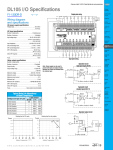
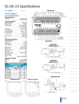
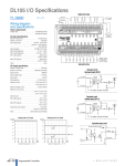
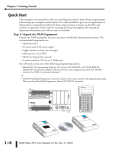
Getting Started 11 In This Chapter. . . . — Introduction — Conventions Used — DL105 Micro PLC Components — Programming Methods — I/O Selection Quick Chart — Quick Start for PLC Checkout and Programming — Steps to Designing a Successful System — Questions and Answers about DL105 Micro PLCs 1--2 Getting Started Getting Started Introduction The Purpose of this Manual Thank you for purchasing a DL105 Micro PLC. This manual shows you how to install, program, and maintain all the Micro PLCs in the DL105 family. It also helps you understand how to interface them to other devices in a control system. This manual contains important information for personnel who will install DL105 PLCs, and for the PLC programmer. If you understand PLC systems, our manuals will provide all the information you need to get and keep your system up and running. Where to Begin If you already understand the DL105 Micro PLC please read Chapter 2, “Installation, Wiring, and Specifications”, and proceed on to other chapters as needed. Be sure to keep this manual handy for reference when you run into questions. If you are a new DL105 customer, we suggest you read this manual completely so you can understand the wide variety of features in the DL105 family of products. We believe you will be pleasantly surprised with how much you can accomplish with AutomationDirect products. Supplemental Manuals If you have purchased operator interfaces or DirectSOFT programming software, you will need to supplement this manual with the manuals that are written for these products. Technical Support We realize that even though we strive to be the best, we may have arranged our information in such a way you cannot find what you are looking for. First, check these resources for help in locating the information: Table of Contents -- chapter and section listing of contents, in the front of this manual S Appendices -- reference material for key topics, near the end of this manual You can also check our online resources for the latest product support information: S Internet -- the address of our Web site is: http://www.automationdirect.com If you still need assistance, please call us at 770--844--4200. Our technical support group is glad to work with you in answering your questions. They are available Monday through Friday from 9:00 A.M. to 6:00 P.M. Eastern Standard Time. S DL105 PLC User Manual, 3rd Edition Getting Started 1--3 Conventions Used When you see the “exclamation mark” icon in the left-hand margin, the paragraph to its immediate right will be a warning. This information could prevent injury, loss of property, or even death (in extreme cases). The entire WARNING: will be in boldface text. Key Topics for Each Chapter The beginning of each chapter will list the key topics that can be found in that chapter. 1 DL105 PLC User Manual, 3rd Edition Getting Started When you see the “notepad” icon in the left-hand margin, the paragraph to its immediate right will be a special note. The word NOTE: in boldface will mark the beginning of the text. 1--4 Getting Started Getting Started DL105 Micro PLC Components The DL105 Micro PLC family is a versatile product line that provides a wide variety of features in a very compact footprint. The PLCs are small, yet offer many features usually found in larger, more expensive systems. These include removeable connectors, RS-232C communication port, and +24V auxiliary power supply. The DL105 Micro PLC Family DL105 Part Number The DL105 Micro PLC family includes eight different versions. All have the same appearance and CPU performance. The CPU offers the same instruction set as our popular DL230 CPU, plus several more instructions specifically designed for machine control applications. All DL105 PLCs have an RS--232C communications port, and the AC-powered versions have an auxiliary +24V output. Units with DC inputs have selectable high-speed input features on four input points. Units with DC outputs offer selectable pulse output capability on the first two output points. All DL105 Micro PLCs offer a large amount of program memory, a substantial instruction set and advanced diagnostics. Details of these features and more are covered in Chapter 4, CPU Specifications and Operation. The eight types of DL105 Micro PLCs provide a variety of Input/Output choices, listed in the following table. Discrete Input Type Discrete Output Type External Power Auxiliary 24V Output High-Speed Input Pulse Output F1--130AR AC Relay 94--240 VAC Yes No No F1--130DR DC Relay 94--240 VAC Yes Yes No F1--130AD AC DC 94--240 VAC Yes No Yes F1--130DD DC DC 94--240 VAC Yes Yes Yes F1--130AA AC AC 94--240 VAC Yes No No F1--130DA DC AC 94--240 VAC Yes Yes No F1--130DR--D DC Relay 10--30 VDC No Yes No F1--130DD--D DC DC 10--30 VDC No Yes Yes Programming Methods DirectSOFT Programming for Windows Two programming methods are available: a software programming package and a handheld programmer. The software and the handheld programmer support RLL (Relay Ladder Logic) and RLL PLUS (STAGE) programming. The DL105 Micro PLC can be programmed with one of the most advanced programming packages in the industry ----DirectSOFT5. This is the most recent version of DirectSOFT, a Windows-based software package that supports familiar features such as cut-and-paste between applications, point-and-click editing, viewing and editing multiple application programs at the same time, etc. DirectSOFT universally supports the DirectLOGIC CPU families. This means that you can use the same DirectSOFT package to program DL05, DL06, DL105, DL205, DL305, DL405 or any new CPU we may add to our product line. (Upgrade software may be required for new CPUs as they become available.) DL105 PLC User Manual, 3rd Edition Getting Started 1--5 Handheld Programmer All DL105 Micro PLCs have a built-in programming port for use with the handheld programmer (D2--HPP), the same programmer used with the DL205 family. The handheld programmer can be used to create, modify and debug your application program. A separate manual discusses the Handheld Programmer. I/O Quick Chart Selection The eight versions of the DL105 have Input/Output circuits which can interface to a wide variety of field devices. In several instances a particular Input or Output circuit can interface to either DC or AC voltages, or both sinking and sourcing circuit arrangements. Check this chart carefully to find the proper DL105 Micro PLC to interface to the field devices in your application. DL105 Partt N P Number b INPUTS OUTPUTS I/O type / commons Sink / Source Voltage Ranges I/O type / Sink / commons Source Voltage / Current Ratings F1--130AR AC / 3 -- 80 -- 132 VAC 90 -- 150 VDC Relay / 4 Sink or Source 12 -- 30 VDC, 7A * 12 -- 250 VAC, 7A * F1--130DR DC / 3 Sink or Source 10 -- 26.4 VDC 21.6 -- 26.4 VAC Relay / 4 Sink or Source 12 -- 30 VDC, 7A * 12 -- 250 VAC, 7A * F1--130AD AC / 3 -- 80 -- 132 VAC 90 -- 150 VDC DC / 1 ** Sink 5 -- 30 VDC, 0.3A (Y0--Y1) 5 -- 30 VDC, 0.6A (Y3--Y7) F1--130DD DC / 3 Sink or Source 10 -- 26.4 VDC 21.6 -- 26.4 VAC DC / 1 ** Sink 5 -- 30 VDC, 0.3A (Y0--Y1) 5 -- 30 VDC, 0.6A (Y3--Y7) F1--130AA AC / 3 -- 80 -- 132 VAC 90 -- 150 VDC AC / 4 -- 20 -- 140 VAC, 47 -- 63 Hz 1.7A * F1--130DA DC / 3 Sink or Source 10 -- 26.4 VDC 21.6 -- 26.4 VAC AC / 4 -- 20 -- 140 VAC, 47 -- 63 Hz 1.7A * F1--130DR--D DC / 3 Sink or Source 10 -- 26.4 VDC 21.6 -- 26.4 VAC Relay / 4 Sink or Source F1--130DD--D DC / 3 Sink or Source 10 -- 26.4 VDC 21.6 -- 26.4 VAC DC / 1 ** Sink 12 -- 30 VDC, 7A * 12 -- 250 VAC, 7A * 5 -- 30 VDC, 0.3A (Y0--Y1) 5 -- 30 VDC, 0.6A (Y3--Y7) * Subject to temperature derating chart. See Chapter 2 Specifications for your particular DL105 version. ** DC outputs have one electrical common, but it is accessible at three terminals on the output connector. DL105 PLC User Manual, 3rd Edition Getting Started There is a separate manual that discusses the DirectSOFT programming software which is included with your software package. 1--6 Getting Started Getting Started Quick Start for PLC Checkout and Programming If you have experience with PLCs, or if you just want to setup a quick example, this example is for you! This example is not intended to tell you everything you need to start-up your system, warnings and helpful tips are in the rest of the manual. It is only intended to give you a general picture of what you will need to do to get your system powered-up. Step 1: Unpack the Recommended DL105 Equipment Unpack the DL105 equipment and verify you have the recommended parts necessary to build this demonstration system. The components are: S DL105 Micro PLC S AC power cord for AC-powered units S F1--04SIM input simulator, or toggle switches (see Step 2 on next page). S Hook-up wire, 16-20 AWG S DL105 User Manual (this manual) S A small screwdriver, regular or #2 Philips type You will need at least one of the following programming options: S DirectSOFT Programming Software, DirectSOFT Manual, and a programming cable (connects the DL105 to a personal computer),or S D2--HPP Handheld Programmer (comes with programming cable), and the Handheld Programmer Manual DL105 PLC User Manual, 3rd Edition Getting Started 1--7 Step 2: Connect Switches to Input Terminals F1--130DR/F1--130DR--CE, F1--130DD/F1--130DD--CE, F1--130DA ON FACTS engineering F1--04SIM (DC input versions) F1--130DR--D, F1--130DD--D (DC-powered versions) Slide simulator under left-most terminals and tighten screws. OFF F1--130AR, F1--130AD, F1--130AA (AC input versions, 120VAC only) ON FACTS engineering F1--04SIM Toggle Switches, UL Listed OFF WARNING: DO NOT wire the toggle switches as shown to 240VAC-powered units. The discrete inputs will only accept 120VAC nominal. Also, remove power and unplug the DL105 when wiring the switches. Only use UL-approved switches rated for at least 250VAC, 1A. Firmly mount the switches before using. NEVER use the input simulator on these units with AC-type discrete inputs. DL105 PLC User Manual, 3rd Edition Getting Started To finish this quick-start exercise or study other examples in this manual, you’ll need to connect some input switches as shown below. For most models, the F1-04SIM Input Simulator is a quick way to install four switches on inputs X0 -- X3. DC-powered units will require routing DC power to the simulator as shown. We recommend using one of the models compatible with the input simulator as you learn the DL105. However, you may wire individual toggle switches to AC-powered units as shown, as long as you follow the instructions in the accompanying WARNING note. 1--8 Getting Started Getting Started Step 3: Connect the Power Wiring Connect the power input wiring for the version DL105 you have. Observe all precautions stated earlier in this manual. For more details on wiring, see Chapter 2 on Installation, Wiring, and Specifications. When the wiring is complete, close the connector covers. Do not apply power at this time. 12/24 VDC Power Input 110/220 VAC Power Input 125 VDC Power Input 94 -- 240 VAC L N 10 -- 30 VDC + -- G 100 -- 240 VDC G + -- G Step 4: Connect the Programming Device Most programmers will use DirectSOFT programming software, installed on a personal computer. Or, you may need the portability of the Handheld Programmer. Both devices will connect the COM1 port of the DL105 via the appropriate cable. Use cable part no. D2--DSCBL (cable comes with HPP) For replacement cable, use part no. DV--1000CBL DL105 PLC User Manual, 3rd Edition Getting Started 1--9 Step 5: Switch on the System Power Step 6: Initialize Scratchpad Memory It’s a good precaution to always clear the system memory (scratchpad memory) on a new DL105. When a unit has been without power for several days, the system RAM contents may have been corrupted and will require initialization. S In DirectSOFT, select the PLC Menu > Setup > Initialize Scratchpad. For additional information, see the DirectSOFT Manual. S For the Handheld Programmer, use the AUX key and execute AUX 54. For additional information, see the Handheld Programmer Manual. Step 7: Enter a Ladder Program At this point, DirectSOFT programmers need to refer to the Quick Start Tutorial in the DirectSOFT Manual. There you will learn how to establish a communications link with the DL105 PLC, change CPU modes to Run or Program, and enter a program. If you are learning how to program with the Handheld Programmer, make sure the CPU is in Program Mode (the RUN LED on the front of the DL105 should be off.) If the RUN LED is on, use the MODE key on the Handheld Programmer to put the PLC in Program Mode. Enter the following keystrokes on the Handheld Programmer. Equivalent DirectSOFT display X0 Y0 OUT CLR C 2 NEXT Clear the Program CLR E $ AUX 4 ENT A STR 0 ENT ENT END GX OUT SHFT A E 4 0 N TMR 3 Move to the first address and enter X0 contact Enter output Y0 ENT D CLR ENT Enter the END statement After entering the simple example program put the PLC in Run mode by using the Mode key on the Handheld Programmer. The RUN indicator on the PLC will illuminate indicating the CPU has entered the Run mode. If not, repeat this step, ensuring the program is entered properly or refer to the troubleshooting guide in chapter 8. After the CPU enters the run mode, the output status indicator for Y should follow the switch status on input channel X0. When the switch is on, the output will be on. DL105 PLC User Manual, 3rd Edition Getting Started Apply power to the system and ensure the PWR indicator on the DL105 is on. If not, remove power from the system and check all wiring and refer to the troubleshooting section in Chapter 8 for assistance. 1--10 Getting Started Getting Started Steps to Designing a Successful System Step 1: Review the Installation Guidelines Always make safety the first priority in any system design. Chapter 2 provides several guidelines that will help you design a safer, more reliable system. This chapter also includes wiring guidelines for the various versions of the DL105 PLC. Step 2: Understand the PLC Setup Procedures The PLC is the heart of your automation system. Make sure you take time to understand the various features and setup requirements. Step 3: Review the I/O Selection Criteria There are many considerations involved when you select your I/O type and field devices. Take time to understand how the various types of sensors and loads can affect your choice of I/O type. Input + PLC Input Sensing -Common Step 4: Choose a System Wiring Strategy It is important to understand the various system design options that are available before wiring field devices and field-side power supplies to the Micro PLC. AC Power Loads DL105 Power Input PLC +24 VDC + Step 5: Understand the System Operation Before you begin to enter a program, it is very helpful to understand how the DL105 system processes information. This involves not only program execution steps, but also involves the various modes of operation and memory layout characteristics. DL105 PLC User Manual, 3rd Edition 8 Outputs 10 Inputs -- Power up Initialize hardware Commons Commons 1--11 Getting Started S S S Standard RLL Programming (see Chapter 5) X0 RLL diagram-style programming is the best tool for solving boolean logic and general CPU register/accumulator manipulation. It includes dozens of instructions, which will also be needed to augment drums and stages. The Timer/Event Drum Sequencer features up to 16 steps and offers both time and/or event-based step transitions. The EDRUM instruction is best for a repetitive process based on a single series of steps. Stage programming (also called RLL PLUS) is based on state-transition diagrams. Stages divide the ladder program into sections which correspond to the states in a flow chart you draw for your process. Timer/Event Drum Sequencer (see Chapter 6) Stage Programming (see Chapter 7) Push--UP RAISE LDD V1076 DOWN CMPD K309482 SP62 Y0 OUT LIGHT LOWER UP Push-DOWN After reviewing the programming concepts above, you’ll be equipped with a variety of tools to write your application program. Step 7: Choose the Instructions Step 8: Understand the Maintenance and Troubleshooting Procedures Once you have installed the Micro PLC and understand the main programming concepts, you can begin writing your application program. At that time you will begin to use one of the most powerful instruction sets available in a small PLC. TMR K30 T1 CNT K10 CT3 Sometimes equipment failures occur when we least expect it. Switches fail, loads short and need to be replaced, etc. In most cases, the majority of the troubleshooting and maintenance time is spent trying to locate the problem. The DL105 Micro PLC has many built-in features such as error codes that can help you quickly identify problems. DL105 PLC User Manual, 3rd Edition Getting Started The DL105 PLC instruction set provides for three main approaches to solving the application program, depicted in the figure below. Step 6: Review the Programming Concepts 1--12 Getting Started Getting Started Questions and Answers about DL105 Micro PLCs Q. What is the instruction set like? A. The instruction set is very close to our popular DL230 CPU. However, there are significant additions, such as the drum instruction and High-Speed I/O capability. Q. Do I have to buy the full DirectSOFT5 programming package to program the DL105? A. No, DirectSOFT100R can be used. It has the same features as the full version of DirectSOFT5 but allows only 100 words of ladder code that can be downloaded to the PLC. It will also program DL05/06/205/305/405 systems, and it is only available for download online. (Order programming cable separately.) 32--bit application, Windows 2000 or Windows XP (Pro or Home) recommended. This software is available at no cost to you. Q. Is the DL105 networkable or expandable? A. No, the DL130 series is stand-alone PLCs. However, our DL205 system is expandable and networkable (with DL240 CPU), yet very compact and affordable. Q. Does the DL105 have motion control capability? A. Yes. The High-Speed I/O features offer either encoder inputs with high-speed counting and presets with interrupt, or a pulse/direction output for stepper control. Three types of motion profiles are available, which are explained in Chapter 3. Q. Are the ladder programs stored in a removable EPROM? A. The DL105 contains a non-removable EEPROM for program storage, which may be written and erased thousands of times. You may transfer programs to/from DirectSOFT on a PC, or the HPP (which does support a removable EEPROM). Q. Does the DL105 contain fuses for its outputs? A. There are no output circuit fuses. Therefore, we recommend fusing each channel, or fusing each common. See Chapter 2 for I/O wiring guidelines. Q. Is the DL105 Micro PLC U.L.R approved? A. The Micro PLC has met the requirements of UL (Underwriters’ Laboratories, Inc.) and CUL (Canadian Underwriters’ Laboratories, Inc.). Q. Can the DL105 accept 5VDC inputs? A. No, 5 volts is lower than the DC input ON threshold. However, many TTL logic circuits can drive the inputs if they are wired as open collector (sinking) inputs. See Chapter 2 for I/O wiring guidelines. DL105 PLC User Manual, 3rd Edition Getting Started 1--13 DL105 PLC User Manual, 3rd Edition Getting Started Q. Which devices can I connect to the Com1 port of the DL105? A. The port is RS-232C, fixed at 9600 baud, and uses the proprietary K-sequence protocol. The port communicates with the following devices: S DV-1000 Data Access Unit or Optimation Operator interface panels S DirectSOFT (running on a personal computer) S D2-HPP handheld programmer S Other devices which communicate via K-sequence protcol should work with the DL105 Micro PLC. Contact the vendor for details.