1
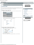
INTREPID User Manual
Library | Help | Top
Moving platform data reduction (C10)
1
| Back |
Moving platform data reduction (C10)
Top
Introduction
Typically, gravity surveys are conducted as part of a seismic acquisition program. In
this chapter we will process some marine gravity data which has been collected
onboard a ship using a LaCoste and Romberg S-meter.
The LaCoste and Romberg Air-Sea gravity meter (Model S) is essentially an electromechanical device with the following modifications from the original land based
meter—the damping is much higher and the unit is on a stabilized platform with
auto-feedback to keep the meter spring tension tending to zero. Monitors of
acceleration and velocity of the motion of the stabilized platform are recorded along
with a logged, filtered observed gravity, a spring tension and cross-coupling.
The processing of marine or aircraft gravity data from the LaCoste and Romberg Smeter follows the process derived from papers published by LaCoste (1973) and
Valliant (1986). The main objective in the process is to use the monitor data to
correct for the motion of the meter.
Factory calibration of the S-meter gives the normal screw–gravity look-up table. In
addition there are 7 monitor gain coefficients used to compute zero-correlation
between the observed gravity and the monitors.
Location of sample data for Cookbooks
Where install_path is the path of your INTREPID installation, the project
directory for the Cookbooks sample data is
install_path\sample_data\cookbooks.
For example, if INTREPID is installed in
C:\Program Files\Intrepid\Intrepid4.5,
then you can find the sample data at
C:\Program Files\Intrepid\Intrepid4.5\sample_data\cookbooks
For information about installing or reinstalling the sample data, see "Sample data for
the INTREPID Cookbooks" in Using INTREPID Cookbooks (R19).
For a description of INTREPID datasets, see Introduction to the INTREPID database
(G20). For more detail, see INTREPID database, file and data structures (R05).
Library | Help | Top
© 2012 Intrepid Geophysics
| Back |
INTREPID User Manual
Library | Help | Top
Moving platform data reduction (C10)
2
| Back |
Moving platform data reduction worked example
Overview
1 Import the raw data into INTREPID line datasets using the Import tool.
2
Use editors to identify and define NS-EW lines of interest.
3
Create ancillary fields (timeofday, YYYYMMDD)
4
Add factory calibration information to the file gravimeter.cfg.
5
Allocate standard field names and INTREPID alias names.
6
Reconstruct the cross-coupling field from the monitor data.
7
Filter the monitor data to remove noise.
8
Reconstruct the observed gravity signal from raw components.
9
Filter the reconstructed observed gravity signal to remove noise.
10 Calibrate, correct for Eotvos, Earth tide, platform motion and drift.
11 Use the profile editor to view reconstructed observed gravity signal.
Preliminary notes
The example data can be found in install_path/sample_data/cookbooks/
moving_platform.
The data we shall use for this example comprises three N-S lines crossing three E-W
lines, for nine intersections. The data is in LaCoste and Romberg Air-Sea System II
format. Air-Sea System II produces two types of data files, with file extensions
“.DAT” and “.ENV”. The data file has 21 comma separated records, recorded once
per second. The environment file contains information about system conditions
during data acquisition, and includes the k-factor and gain coefficients for the
monitors. It is recorded once every 10 seconds.
The data files are in the Rawdata directory and called S-133.DAT and S-133.ENV.
Library | Help | Top
© 2012 Intrepid Geophysics
| Back |
INTREPID User Manual
Library | Help | Top
Moving platform data reduction (C10)
3
| Back |
Steps to follow
1
Import the ASCII files S-133.DAT and S-133.ENV into INTREPID line
datasets.
For the file S-133.DAT, use ASCII Columns input format with the following
data definition file (DDF). In our worked example, this DDF is called
import_dat.ddf.
TYPE(LINE)
char 1-4 character*10
Seq 6-6 integer*4
Year 6-9 integer*4
Month 11-12 integer*4
Day 14-15 integer*4
HH 17-18 integer*4
MM 20-21 integer*4
SS 23-27 real*4
Jday 29-31 integer*4
Gravity 33-40 real*4
Spr_ten 42-49 real*4
Beam 51-61 real*4
Vcc 63-70 real*4
AL 72-79 real*4
AX 81-88 real*4
VE 90-97 real*4
AX2 99-106 real*4
Xacc2 108-115 real*4
Lacc2 117-124 real*4
Xacc 126-133 real*4
Lacc 135-142 real*4
Eotvos 144-151 real*4
longitude 153-165 real*8 PROJ(GEODETIC,WGS84) IsX
latitude 167-179 real*8 PROJ(GEODETIC,WGS84) IsY
velocity 181-187 real*4
heading 189-196 real*4
GROUP BY Seq
You can run the INTREPID Import tool either interactively or in batch. If you
wish to run it in batch, the task specification (.job) file import_dat.job is set
up to perform the operation.
To run the task, launch a command window and type the command:
fmanager.exe –batch import_dat.job
INTREPID imports the data and creates a Line dataset called
marine_grav..DIR. This is our primary dataset. Note that because we are
creating a Line dataset, we need to define a line or sequence number. The format
of the raw data does not include an explicit line number, so we need to create one.
The Seq field in the DDF file is defined for this purpose. It does not matter what
value it is assigned on import, so long as it exists. We will be changing it later.
Library | Help | Top
© 2012 Intrepid Geophysics
| Back |
INTREPID User Manual
Library | Help | Top
Moving platform data reduction (C10)
4
| Back |
For the file S-133.ENV, use ASCII Columns input format with the following
data definition file (DDF). In our worked example, this DDF is called
import_env.ddf.
TYPE(LINE)
char 1-4 character*10
Seq 6-6 integer*4
Year 6-9 integer*4
Month 11-12 integer*4
Day 14-15 integer*4
HH 17-18 integer*4
MM 20-21 integer*4
SS 23-27 real*4
Jday 29-31 integer*4
meter_id 33-42 character*10
meter_pressure 44-51 real*4
meter_temp 53-60 real*4
ambient_temp 62-69 real*4
k_factor 71-81 real*4
Vcc_coeff 83-90 real*4
AL_coeff 92-99 real*4
AX_coeff 101-108 real*4
VE_coeff 110-117 real*4
AX2_coeff 119-126 real*4
serial_filt_length 128-131 real*4
QC_filter_length 133-136 real*4
GROUP BY Seq
You can run the INTREPID Import tool either interactively or in batch. If you
wish to run it in batch, the task specification (.job) file import_env.job is set
up to perform the operation.
To run the task, assuming that the task specification file is called
import_env.job, use the command:
fmanager.exe –batch import_env.job
INTREPID will import the data and create a Line dataset called
marine_env..DIR. Note that because we are creating a Line dataset, we need to
define a line or sequence number. Similar comments apply to the Seq field as
before.
2
Define a fiducial field in our primary dataset. Allocate some standard INTREPID
alias names. Then use the INTREPID editors to identify and define the NS-EW
lines of interest, and delete non-essential data such as transit lines.
To use the INTREPID editors to manipulate our data, it is necessary to define a
fiducial field (essentially a sequential counter) in our dataset. Acquisition time
makes a suitable fiducial quantity, however our dataset contains the time as HH
MM SS, which is not in a suitable format for us to use. Therefore we will use the
Spreadsheet editor to convert HH MM SS to time in seconds after midnight. You
can perform this operation either interactively or in batch. If you wish to run it in
batch, the task specification (.job) file convert_time.job is set up to perform
the operation.
Library | Help | Top
© 2012 Intrepid Geophysics
| Back |
INTREPID User Manual
Library | Help | Top
Moving platform data reduction (C10)
5
| Back |
To run the task use the command:
fmanager.exe –batch convert_time.job
INTREPID will perform the task and create a new field called Time_sec. This
will be our fiducial field.
Having created a fiducial field, we now need to define it as the Fiducial Alias so
that INTREPID knows about it (see example in List of aliases). Launch the
INTREPID Project Manager and navigate to your working directory. Highlight
the dataset marine_grav..DIR and click on the Fields tab. Set the Time_Sec
field to Alias Fiducial. Since it is a line dataset we also need to define a Line
Alias, so set the Seq field to Alias LineNumber.
Now we have defined appropriate fields as Aliases, we can display our dataset in
the Flight Path Editor. Launch the Flight Path Editor and load the
marine_grav..DIR dataset. It should appear as a single long line. The reason
for this is that the raw data contains some corrupted records which is affecting the
latitude and longitude ranges. Use the zoom function to examine the eastern end
of the line. If you zoom right in you will see the three N-S lines criss-crossing the
three E-W lines. They are the lines we want to process. Presently they exist as a
single long line. We need to split the single line into separate lines. The other lines
are transit lines which we want to delete from our dataset.
This process of preparing the data for processing may seem tedious but it is a
necessary part of the data processing operation. If you do not wish or do not have
time to perform the editing and splitting of the dataset lines, you can skip this
section and proceed to Step 3. An edited and prepared dataset is included for you
in the example data (marine_grav_prepared..DIR).
Dataset editing is best accomplished using a combination of INTREPID editors.
With the Flight Path editor open, use the query function to report the start and
end fiducial for each of the three N-S and three E-W line segments we want to
process. Starting at the western end of the northern-most E-W line, the query
function should report a start fid value of approximately 8465, and an end fid
value of approximately 10521. Write these fids down as you go. You should end
up with six sets of start and end fids, which define the start and end points of our
six lines of interest.
Do not clip the lines too close to where the ship turns. The survey data becomes
unreliable when the ship changes direction.
Library | Help | Top
© 2012 Intrepid Geophysics
| Back |
INTREPID User Manual
Library | Help | Top
Moving platform data reduction (C10)
6
| Back |
When you have completed this part of the exercise, close the Flight Path editor.
Next, launch the Spreadsheet editor and load the marine_grav..DIR dataset.
You may want to use the Re-order columns function to rearrange the field
ordering in the editor. Using the Edit-Find function, search for the start fid of the
first line segment. In the Search For box, type Time_sec == 8465, and click the
Forward button. You can leave the Edit-Find box open. Under Edit, choose Split
Group At Current Row. This operation will create a new group (line segment) in
the dataset.
Next, search for the end fid of the first line segment, which is Time_sec = 10521.
In the Search For box, type Time_sec == 10521, and click the Forward button.
Under Edit, choose Split Group At Current Row. This operation will create a new
group (line segment) in the dataset.
Continue searching and splitting for all 6 start and end fiducial pairs. When
done, you should have 13 groups in your dataset. Press Cancel to close the EditFind box.
Now that our dataset consists of mutiple groups, we need to allocate each group a
unique Seq (line) number. With the Spreadsheet editor still open, choose the
Edit-Replace function. Click the Load Formula button and load Seq.frm. Click
OK. This formula overwrites the value of Seq and assigns a sequential number to
each group in the dataset.
Now launch the Flight Path editor. Load the marine_grav..DIR dataset. Zoom
in on the survey area as you did before. Choose Line Display - Single Line in Red.
Highlight the first line number and click OK. That line will display in red. By
choosing each line number in turn, you can identify the line numbers of the three
N-S and E-W lines of interest. You should find that they correspond to lines 2, 4 ,
6, 8, 10, 12 of our dataset. We want to keep these lines and delete the rest.
Library | Help | Top
© 2012 Intrepid Geophysics
| Back |
INTREPID User Manual
Library | Help | Top
Moving platform data reduction (C10)
7
| Back |
Close the Flight Path editor. Using the Spreadsheet editor, navigate to Seq 1.
Choose the Edit - Delete Current Group function. You may find it necessary to
toggle to the next or previous group to force a screen refresh. Navigate to the next
Seq you wish to delete (Seq 3) and repeat the deletion. Continue deleting the nonessential lines until the dataset contains only the six lines we are interested in.
When you have done this, re-sequence the lines using Edit-Replace - Load
Formula Seq.frm.
Exit from the Spreadsheet editor. Launch the Flight Path editor and load the
marine_grav..DIR dataset. Check that you have three E-W and three N-S
lines in the dataset.
3
Use the INTREPID editors to create some additonal fields (timeofday,
YYYYMMDD), which are required for the processing of the data.
Note: If you skipped the editing section of the tutorial, you will need to rename
the supplied dataset marine_grav_prepared..DIR to marine_grav..DIR in
order that the supplied batch job files work correctly. Use the Project Manager to
rename the dataset.
In addition to the fields already in the dataset, INTREPID requires some extra
fields to be created. We need to create a timeofday field, which is time in decimal
hours, and also a YYYYMMDD field, which can be easily created, since we already
have the Year, Month and Day in our dataset.
You can perform these operations either interactively or in batch. If you wish to
run them in batch, the task specification (.job) files timeofday.job and
YYYYMMDD.job are set up to perform the operations.
To run the tasks use similar commands as before, eg:
fmanager.exe –batch timeofday.job
fmanager.exe –batch YYYYMMDD.job
INTREPID will perform the tasks and create new fields as specified by the task
files.
4
Add factory calibration information to the file gravimeter.cfg.
The gravimeter.cfg file is stored in the INTREPID config directory. The 'S'
meter entry also allows for the extra calibration factors in the usual INTREPID
block structure language syntax.
Normally when starting a job you would add a new entry to this file, identifying
the meter which was used to acquire the data. In this worked example the S133
meter was used to acquire the data, and we have already added an entry into the
gravimeter.cfg file for this meter. The gain factors have been taken from the
marine_env..DIR dataset. The entry for the S133 meter appears as follows:
GRAVIMETER,S133
Parameters Begin
# qingdao test data, Sept 2003.
Calibration_Factor = 0.9978
BEAM_SCALE_FACTOR= 0.096360
VCC_MON=
-0.525
AL_MON=
-0.04580
Library | Help | Top
© 2012 Intrepid Geophysics
| Back |
INTREPID User Manual
Library | Help | Top
Moving platform data reduction (C10)
8
| Back |
AX_MON=
VE
=
AX2 =
XACC2 =
LACC2 =
Parameters End
5
0.05
1.064
0.33
0.0
0.0
Allocation of standard field names and aliases.
Aliases can be declared either interactively or by using the batch language. To
declare them interactively, use the Project Manager to highlight the dataset. Tab
to Fields, then click under the Alias column and select the More option.The
Configure Aliases dialog box will appear. Tab to Marine, and use the pull-down
menus to allocate alias names for Spring Tension, Beam, Vcc, AL, AX, VE, AX2,
Xacc2, Lacc2. Note: at this point there is no Cross Coupling field in the
dataset.
Tab to Levelling and allocate alias names for DateCode and TimeOfDay.
DateCode is aliased to YYYMMDD, and TimeOfDay is aliased to timeofday.
You must also allocate an alias name for ObsGravity. Currently this must be done
manually. Open the marine_grav.isi file in a text editor and insert the line
Alias = ObsGravity, in the Begin-End syntax block for the field Gravity.
If you wish to allocate the alias names by using the batch language, refer to the
task specification (.job) file alias.job.
6
Reconstruct the cross-coupling error field.
The cross-coupling error field (CC_reconstruct) can be calculated from 5 of the
monitors and the monitor gain factors using the following equation:
CCreconstruct = Cvcc * VCC + Cve * VE + Cal * AL + Cax * AX + Cax2 * AX2
It uses the Marine Aquisition aliases to identify the monitor fields, VCC, VE, etc.
These should be set to the unfiltered monitor fields, as you did in Step 5. The
monitor gain factors are stored in the gravimeter.cfg file.
This process must be run in batch. The task specification (.job) file
CC_reconstruct.job is set up to perform the operation.
Once the job file has been run and the CC_reconstruct field has been created,
you must use the Project Manager to set the CrossCoupling alias to
CC_reconstruct.
Note: Under some circumstances you may get the following error message in the
log file after running the batch file:
ERROR: The input cross coupling data base field has not been
defined.
If you get this error message, then do the following:
•
Create a new field CC_reconstruct in the marine_grav..DIR
•
Alias it to CROSS_COUPLING
Then rerun fmanager.exe -batch CC_reconstruct.job
7
Library | Help | Top
Filter the monitor data to remove noise, and reset INTREPID aliases to the
filtered monitors.
© 2012 Intrepid Geophysics
| Back |
INTREPID User Manual
Library | Help | Top
Moving platform data reduction (C10)
9
| Back |
All monitors are to be low pass filtered. The monitors are extremely noisy and this
is a vital step. The aim is to isolate those frequencies in the monitor data that is
associated with wave action, so the LowPass is designed to filter out spurious high
frequency noise. The contractor used 10 minute RC filtering as a Quality Control
measure during data acquistion, and so introduced a lag of 300 seconds into the
Observed Gravity record.
Library | Help | Top
© 2012 Intrepid Geophysics
| Back |
INTREPID User Manual
Library | Help | Top
Moving platform data reduction (C10)
10
| Back |
RC Filtering
LaCoste recommends 3 passes of 27 sec and 2 passes of 150 sec using RC
(resistance-capacitance) type filters. A Compound filter has been set up in the
INTREPID filter library that can be used by the line filter tool either interactively
or in batch to perform this style of RC filtering. You can experiment with
different filters if you have time. We have found that the RC style of filtering
works best on very noisy monitor data.
Filter Processing
This filtering is done using the line filter tool. Note, the data is collected on a one
second basis, so set Fid factor to 1.0. A job file to pass all monitors through
whichever variation on filtering is required, is used to automate this process. The
monitors filtered are VCC, AL, AX, VE, AX2, XACC2, LACC2. Each of these
monitors is acquired at 25 Hz in real time in the ZLS system and logged at 1
second intervals.
The task specification (.job) file filter_monitors.job is set up to perform
the filtering.
At this stage it is important to check the data visually to ensure that the filtering
process is performing as expected. From the INTREPID editors menu, launch the
Profile editor. Load two or three of the unfiltered and filtered fields and visually
check the results of the filtering. The following is a snap shot of data
demonstrating this.
The most important monitors are Beam, CC, Vcc, AL, VE and AX. The other
monitors play less part in the correction for a well adjusted meter.
Having done the filtering, you now need to re-define the INTREPID Marine
Acquisition aliases to point to the filtered fields. Aliases can be defined either
interactively or by using the batch language, as you did previously.
The INTREPID aliases should now point to the following fields: Vcc_filt, AL_filt,
AX_filt, VE_filt, AX2_filt, Xacc2_filt, Lacc2_filt.
Library | Help | Top
© 2012 Intrepid Geophysics
| Back |
INTREPID User Manual
Library | Help | Top
8
Moving platform data reduction (C10)
11
| Back |
Reconstruct the Observed Gravity signal.
The contractor-supplied observed gravity field is heavily filtered. Typically they
may use a 10 minute filter. The observed gravity can be reconstructed and less
heavily filtered to increase the signal content. This is done from the raw
components of the measurement, namely, Spring Tension, Beam velocity and
Cross Coupling correction.
Reconstruct G = Spring + k * Beam’ + CrossCoupling
The factor "k" is the gain factor to calibrate the beam slope to mGal and is
provided in the calibration table. For S133, this is 0.096360. Units are Still meter
units.
This process must be run in batch. The task specification (.job) file
gravity_reconstruct.job is set up to perform the operation. The process
writes out a report file which you should examine after running the process. In
this example it is called reconstruct.rpt.
The following diagram shows an example of the filtered contractor gravity versus
the reconstructed lagged gravity. (The dataset used in this diagram is not the
same as your test data).
9
Filter the reconstructed observed gravity signal.
The reconstructed observed gravity contains a lot of high frequency noise. It is
necessary to remove this noise by using the same filter that was used on the
monitor data. This is done before the crosscorrelation process, so that the
monitors and the reconstructed observed gravity will have a similar frequency
content.
The filtering can be done either interactively or in batch. The task specification
(.job) file filter_reconstruct.job is set up to perform the operation.
10 Calibrate, correct for Eotvos, Earth tide, platform motion and drift.
The Stabilized Platform Correction performs several processes, as follows:
Calibration and Conversion
INTREPID converts the raw gravity reading as measured in counter units to
relative mGal using a lookup table and interpolating between ranges.
Library | Help | Top
© 2012 Intrepid Geophysics
| Back |
INTREPID User Manual
Library | Help | Top
Moving platform data reduction (C10)
12
| Back |
Earth Tide correction
The Longman Earth Tide model approximately describes the Sun and Moon tidal
forces at any point and time on Earth. It is not numerically a large error
correction - typically 0.1 mGal applies.
Eötvös correction
The largest source of error is caused by the Eötvös effect. This correction
compensates for the velocity of the gravimeter across the rotating Earth, and it
can typically be ±15 mGal. INTREPID uses the calculated ship or aircraft velocity
and bearing to make this correction.
Cross correlation analysis and correction
There should be no crosscorrelation between variations in observed gravity and
variations in any of the monitors. If crosscorrelation exists then the observed
gravity signal is being affected by platform motion. Correction for platform motion
is achieved by subtracting fractions of the monitor data from the observed gravity,
to make a zero correlation. Each monitor has a gain factor which determines what
fraction of the monitor is subtracted.
There are two options for deriving the monitor gain factors:
STABILIZED_PLATFORM_CORRECTION. This option uses the factory set gain
factors for each monitor. These are stored in the gravimeter.cfg file.
STABILIZED_PLATFORM_CALIBRATE_CORRECT. This option computes the gain
factors by calculating how the observed gravity correlates with all or some of the
monitors. INTREPID uses the curvature product cross-correlation approach,
accumulating a matrix of all observations for straight-line segments and solving
them for a best fit.
Using the report which the process creates, you can check for zero correlation line
by line or for the total survey and recalculate line-by-line or total-survey gain
factors.
Meter drift, absolute tie-in
The data can be corrected for meter drift by taking repeated Still readings during
the course of the survey. A Still value taken at the dock or airfield is used to tie in
the relative gravity data to an absolute value.
The Stabilized Platform Correction process must be run in batch. The task
specification (.job) file platform_correction.job is set up to perform the
operation. It requires a meter number, input dataset and observed gravity that
can either be the contractor supplied or the reconstructed gravity. The process
writes out a report file which you should examine after running the process. In
this example it is called reconstruct.rpt.
Peculiar to the marine gravity practice, is the use of a linear curvature function to
assess the derivatives of observed acceleration components and gravity. This is
used:
Library | Help | Top
•
For the purpose of minimizing the cross-correlation between ship movement
and gravity
•
As a "spike" detector in those parts of the survey that may be associated with
ship turning or such like.
•
To assess overall improvement in gravity estimation as measured by the ratio
of RMS of before and after signal.
© 2012 Intrepid Geophysics
| Back |
INTREPID User Manual
Library | Help | Top
Moving platform data reduction (C10)
13
| Back |
The report file contains a summary of curvature for the input and output fields. It
also quotes improvement in ratio of curvature as ratio of RMS of output over
input, on a line-by-line basis and also a total survey basis. The report should be
examined carefully. The aim is to get the ratio as low as possible, indicating that
the processing has resulted in a smoother gravity signal, even though it has had
no more filtering. An improvement ratio of 0.9 is typical for this dataset.
Hint : Unless a large amount of data taken with many different headings are
analysed, it is not safe to use more than two or three monitors in the
crosscorrelation because the monitors are not entirely independent.
The report also contains a summary of the cross correlation calculation, in the
form of a matrix of cross-correlation coefficients for all monitors and observed
gravity. The first row gives the correlation coefficient for each monitor correlated
with observed gravity. A correlation coefficient of unity indicates perfect
correlation and zero indicates no correlation. A negative value indicates the
signals are out of phase.
11 Use the profile editor to view the reconstructed observed gravity signal.
Generated Outputs from Gravity Processing
The Corrected gravity field generated by this process has the following done to it
1
For each record where the navigation data is not nulled, a cross-correlation
correction is computed using the filtered monitors and the gain factors.
2
The gravity screw reading is converted to an adjusted reading via the
manufacturers lookup table.
3
The Eötvös correction is computed
4
The Earth Tide correction is computed
5
The Absolute value at the Still, or dock locations was added to all meter readings
after subtracting the still value for the meter
All of these corrections are added and form the basis of the output.
References
Valliant, Herbert (1986). ‘The La Coste & Romberg Air/Sea Gravity Meter: An
Overview’, CRC Handbook of Geophysical Exploration at Sea, 2nd Edition, Chapter 7.
LaCoste, Lucien J.B. (1973). ‘Cross-correlation Method for Evaluating and Correcting
Shipboard Gravity Data’ Geophysics, Vol. 38, No. 4, pp. 701–709.
Library | Help | Top
© 2012 Intrepid Geophysics
| Back |
INTREPID User Manual
Library | Help | Top
Moving platform data reduction (C10)
14
| Back |
Sample file listings
List of aliases
Alias Begin
Fiducial= Time_sec
LineNumber= Line
X
= Easting
Y
= Northing
LineType= Linetype
TimeOfDay = Time
DateCode = date
Velocity = vel
Bearing = Azimuth
ObsGravity = GRAVITY
BEAM = Beam
CC
= CC_reconstruct
VCC = Vcc_filt
AL
= AL_filt
AX
= AX_filt
VE
= VE_filt
AX2 = AX2_filt
XACC2 = Xacc2_filt
LACC2 = Lacc2_filt
VCCPHASE= VCCPHASE
AXPHASE= AXPHASE
ALPHASE= ALPHASE
Alias End
Library | Help | Top
© 2012 Intrepid Geophysics
| Back |
INTREPID User Manual
Library | Help | Top
Moving platform data reduction (C10)
15
| Back |
Detailed explanation of other inputs and options:
Lag factor
The data may lag, as it is filtered in the hardware. Thus a Lag factor in reading units
for a reading every second is required and for a 10 minute averaging scheme, a
reading is logged 5 minutes behind or 300 seconds.
In the Marine Begin ... End block, set
GravityLAG = 300
Eötvös
Make the Eötvös correction
In the Marine Begin ... End block, set
IgnoreEotvos = No
A velocity and latitude are required for this. The velocity alias must be set. A user
friendly code option to convert from UTM to latitude obviates any special action for
the latitude.
Do Earth Tide Correction
In the Levelling Begin ... End block, set
SkipEarthTideCorrection =YES/NO.
Offset of Time Zone from UTC in hours
In the Marine Begin ... End block, set:
UTC_Offset = 1.
Other required time fields for this are TimeOfDay in decimal hours, set via the alias.
And also DateCode in YYMMDD format, also set by alias
Do the Cross Correlation correction
In the Marine Begin ... End block, set:
IgnoreDecorrelation= No
Also make sure the alias fields are pointing to the correct monitors.
A report of the RMS of the before and after observed gravity curvatures is made
together with the ratio.
Still Readings, Datum, Drift Correction
The in-port still readings are of use for two purposes:
Library | Help | Top
•
A report for drift correction.
•
A tie-in to the Fundamental Network.
© 2012 Intrepid Geophysics
| Back |
INTREPID User Manual
Library | Help | Top
Moving platform data reduction (C10)
16
| Back |
Example gravity processing reports
Reconstruction of observed gravity report
****************************************************
Intrepid Gravity v3.5 (release) cut 112
Start processing - 23/ 5/2001 10: 8:37
****************************************************
Reconstructing Observed Gravity for a stabilized L&R S meters. For survey database ../DB/grav/
----------------------------------------------------------------Contractor supplied Observed gravity
Reconstructed gravity field
Spring Tension
Beam
Position
Cross
Coupling
Gain Factor for Beam Slope
:
:
:
:
:
:
../DB/grav/GRAVITY
../DB/grav/reconstruct
../DB/grav/Spr_ten
../DB/grav/Beam_filt
../DB/grav/CC_filt
-1.6001
LCR_S(LCS): Meter - S32, Adjustment to Manufacturers Scale Factor 1.000000
Manufacturers settings
Long Accelerometer * Beam Position(VCC)
:
0.2350
Long Accelerometer * Beam Velocity(AL)
:
0.2910
Cross Accelerometer * Beam Velocity(AX)
:
0.2500
Square of the Beam Velocity(VE)
:
0.0066
(Cross Accelerometer)**2 * Beam Velocity(AX2) :
0.0000
(Cross Accelerometer)**2(XACC2)
:
0.0000
(Long Accelerometer)**2(LACC2)
:
0.0000
Stabilized platform corrections report.
****************************************************
Intrepid Gravity v3.5 (release) cut 112
Start processing - 16/ 5/2001 18:52: 1
****************************************************
Calculating stabilized corrections for L&R S meters. For survey database ../DB/grav/
----------------------------------------------------------------Observed gravity field
Converted gravity field
Long Accelerometer * Beam Position(VCC)
Long Accelerometer * Beam Velocity(AL)
Cross Accelerometer * Beam Velocity(AX)
Square of the Beam Velocity(VE)
(Cross Accelerometer)**2 * Beam Velocity(AX2)
(Cross Accelerometer)**2(XACC2)
(Long Accelerometer)**2(LACC2)
Easting/Latitude
Northing/Longitude
Velocity
Bearing/Heading
(North = 0)
DateCode
(YYMMDD)
TimeOfDay (decimal local hours)
Input datum
Gravity units
:
:
:
:
:
:
:
:
:
:
:
:
:
:
:
:
:
../DB/grav/Gravity
../DB/grav/CorrectedGravity
../DB/grav/Vcc_filt
../DB/grav/AL_filt
../DB/grav/AX_filt
../DB/grav/VE_filt
../DB/grav/AX2_filt
../DB/grav/Xacc2_filt
../DB/grav/Lacc2_filt
../DB/grav/Northing
../DB/grav/Easting
../DB/grav/vel
../DB/grav/Azimuth
../DB/grav/YYMMDD
../DB/grav/timeofday
IGSN71
Milligals
LCR_S(LCS): Meter - S32, Adjustment to Manufacturers Scale Factor 1.000000
Manufacturers settings
Long Accelerometer * Beam Position(VCC)
:
0.2350
Long Accelerometer * Beam Velocity(AL)
:
0.2910
Cross Accelerometer * Beam Velocity(AX)
:
0.2500
Square of the Beam Velocity(VE)
:
0.0066
(Cross Accelerometer)**2 * Beam Velocity(AX2) :
0.0000
(Cross Accelerometer)**2(XACC2)
:
0.0000
(Long Accelerometer)**2(LACC2)
:
0.0000
using the above given factors for each monitor to correct motion
Performing an Earth Tide Correction step UTC offset
1.000 hr
Group 0 , Number of raw obs
39225
Library | Help | Top
© 2012 Intrepid Geophysics
| Back |