1
phyCORE-AM335x
Part II: PCM-953 / phyCORE-AM335x Carrier Board
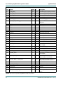
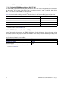
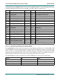
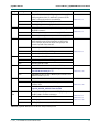
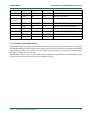
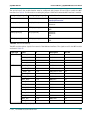
Pin #
Signal
Type
SL
Description
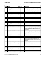
32
LVDS_CLKOUTP
LVDS
3.3 V
LVDS clock channel positive output
33
GND
-
-
Ground
34
TOUCH_X+
Analog
3.3 V
Touch
35
TOUCH_X-
Analog
3.3 V
Touch
36
TOUCH_Y+
Analog
3.3 V
Touch
37
TOUCH_Y-
Analog
3.3 V
Touch
38
n.c.
-
-
not connected
39
GND
-
-
Ground
40
n.c.
-
-
not connected
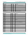
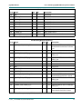
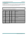
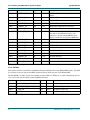
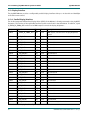
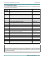
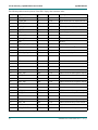
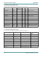
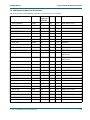
Table 57: PDI Data Connector X4 Signal Description
1.
Provided to supply any logic on the display adapter.
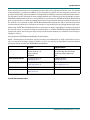
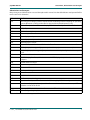
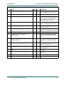
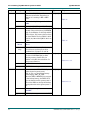
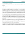
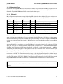
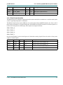
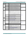
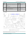
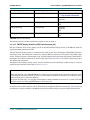
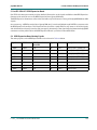
The table below describes the auxiliary interfaces at display data connector X4.
Interface or Signal
Description
I2C0
I2C interface for a optional EEPROM, or other I2C devices. Additional information on the I2C interfaces can be found in Section 3.9.5.
SPI0
SPI interface to connect optional SPI slave. Jumper JP17 must be closed to use
the SPI interface, which is addressable at SPI0 device 0. The LCD from PHYTEC
does not include a SPI interface.
CHOOSE_LCD_OEn
Can be used to enable or disable the display. CHOOSE_LCD_OEn is driven by a
logic decoder which is controlled with jumpers JP3 and JP4.
See section Section 4.2.5
X_ECAP0_IN_PWM0_OUT
PWM output from the AM335x to control the brightness of a display's backlight
(0% = dark, 100% = bright).
TOUCH
Analog touch-screen interface signals. These TOUCH signals connect to the
AIN[3:0] signals of the AM335x.
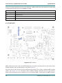
Table 58: Auxiliary Interfaces at PDI Data Connector X4
L-771e_1 © PHYTEC Messtechnik GmbH 2012
98