1
phyCORE-AM335x
Part II: PCM-953 / phyCORE-AM335x Carrier Board
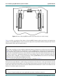
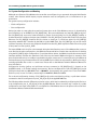
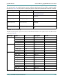
4.3.14 Audio (X14, X15, X16, X17)
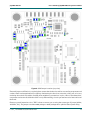
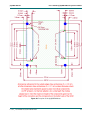
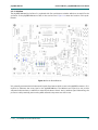
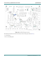
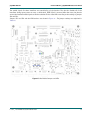
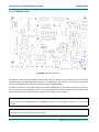
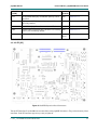
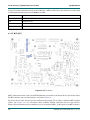
Figure 31: Audio Connectors (X14, X15, X16, X17)
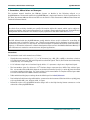
The audio interface provides a method of exploring the AM335x's audio capabilities. The phyCORE-AM335x
Carrier Board is populated with a Wolfson Microelectronics WM8974 audio codec at U20. The WM8974 is
connected to the AM335x's McASP0 interface to support stereo microphone input, stereo headphone output,
mono output, and direct speaker output.
The phyCORE-AM335x accesses the WM8974 registers via the I2C0 interface at address 0x1A (7-bit MSB
addressing). Audio devices can be connected at X14, X15, X16 and X17.
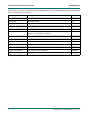
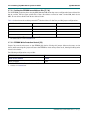
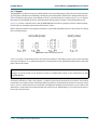
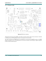
The carrier board's audio interface includes three hardware configuration jumpers: JP5, JP6 and JP13.
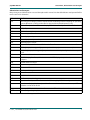
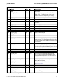
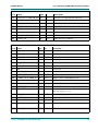
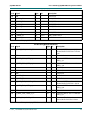
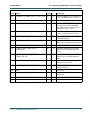
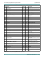
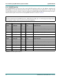
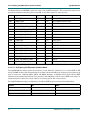
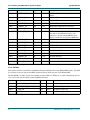
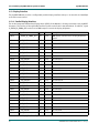
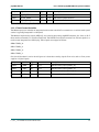
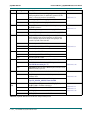
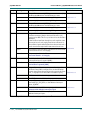
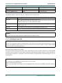
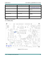
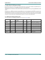
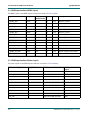
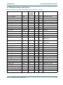
These are described in paragraphs below. The audio connectors are listed in Table 61.
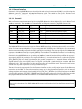
Jumper JP5 selects the source for the audio codec's microphone input from connector X14. The default
configuration (1+2) connects the microphone input to X14's "R" signal. If JP5 is set to (2+3) then the
microphone input connects to X14's "T" signal.
Jumper JP6 allows flexible control over the audio codec's master clock source (MCLK). The audio codec's master
clock can range from 12.288 MHz to 50 MHz. In the default position (2+3) the codec is clocked from the
module's X_MCASP0_AHCLKX clock signal. If J6 is set to (1+2) the clock is generated by a crystal oscillator
(12.2880 MHz) at OZ1 on the carrier board.
L-771e_1 © PHYTEC Messtechnik GmbH 2012
102