1
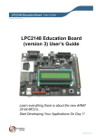
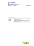
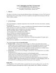
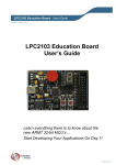
AN10908
Wakeup from Deep Sleep using the CANActivity interrupt
Rev. 01 — 25 February 2010
Application note
Document information
Info
Content
Keywords
LPC1700, CAN Controller, CAN Activity, WIC, NVIC, Deep Sleep, Powerdown
Abstract
This application note is meant to be accompanied with the CAN Activity
wakeup sample project. It briefly discusses on how to utilize the CAN
Activity interrupt to wake up the LPC1700 and service CAN bus activity.
AN10908
NXP Semiconductors
CAN activity wakeup
Revision history
Rev
Date
Description
01
Initial version.
20100225
Contact information
For additional information, please visit: http://www.nxp.com
For sales office addresses, please send an email to: [email protected]
AN10908_1
Application note
All information provided in this document is subject to legal disclaimers.
Rev. 01 — 25 February 2010
© NXP B.V. 2010. All rights reserved.
2 of 12
AN10908
NXP Semiconductors
CAN activity wakeup
1. Introduction
The LPC1700 contains up to two high performance CAN controllers. These CAN
controllers are designed to provide a full implementation of the CAN protocol according
to the CAN specification version 2.0B.
CAN networks are commonly used in automotive, industrial, and high speed network
applications and can be utilized using low cost twisted-pair media. By design the CAN
protocol is a multi-master network architecture. This allows any particular CAN node to
send a message to any one or more other CAN nodes on that particular bus.
The full details on how CAN networks function is not discussed in this application note. It
is recommended to become familiarized with these networks before continuing this
document. Another application note from Keil can be found at
http://www.standardics.nxp.com/support/documents/microcontrollers/pdf/lpc17xx.can.arm
.pdf. It briefly describes on how to create a CAN network using the LPC1700.
1.1 CAN activity
A CAN network is designed on a shared bus network; meaning that all CAN controllers
(or nodes) on a particular bus will send and receive packets on the same physical
medium. When no device is currently transmitting, then the bus is known to be in an
“Idle” state. Any transition from an “Idle” state to a “non-Idle” state is referred to as
“activity” throughout this application note. Activity on the bus can be generated from one
or more nodes at once. It is important to note that according to CAN specifications, if two
or more nodes are transmitting at the same time, the node with a highest priority will gain
control of the bus.
1.2 Reduced power modes
One of the features of the LPC1700 is that it can be put into four different reduced power
modes: Sleep, Deep Sleep, Power-down and Deep Power-down. In regards to this
application note we will be primarily focusing on the Deep Sleep and Power-down
modes.
The CANActivity interrupt will only function when the device is either in Deep Sleep or
Power-down mode.
In sleep mode, any enabled interrupt will wakeup the LPC1700; however, in this mode
the CAN_IRQHandler will process the incoming CAN packet.
In Deep Power-down mode the LPC1700 will only wake up when an external reset or
RTC interrupt is generated; therefore, this reduced power mode is not applicable to this
application note.
Full details on what the reduced power modes do to the LPC1700 can be found in its
user manual. For our purposes we will briefly summarize the information that applies to
this application note.
AN10908_1
Application note
All information provided in this document is subject to legal disclaimers.
Rev. 01 — 25 February 2010
© NXP B.V. 2010. All rights reserved.
3 of 12
AN10908
NXP Semiconductors
CAN activity wakeup
Table 1.
Reduced power modes
This table is intended just as a quick summary applicable to this application note. Full details on the
LPC1700’s reduced power modes are found in its user manual.
Power Mode
Short summary
Sleep
A reset or any enabled interrupt will wake up the device. The clock to the
ARM core is; whereas the clock to the peripherals continues to run. This
power mode does not require any re-initialization of the PLL after being
waked up.
Deep Sleep
The IRC remains running while the main oscillator is powered down. Flash
is put into standby mode.
Reset, NMI, EINT0-3, GPIO Interrupts, Ethernet WOL, Brownout Detect,
RTC Alarm Interrupt, WDT timeout, USBActivity, or CANActivity interrupt
will wake up the device. Afterwards, it requires re-initialization of the PLL
and clock dividers.
Power-down
Same as Deep Sleep; however, flash and the IRC are also powered down.
Deep Power-down
Power is shut off to the entire chip. Only reset or the RTC can wake up the
device.
2. Requirements
2.1 Hardware
This sample software was developed on Keil’s MCB1700 development board which
features an LPC1768 microcontroller. This particular microcontroller contains two CAN
controllers. In this sample project only CAN1 is used to receive CAN packets.
Fig 1. Keil’s MCB1700 featuring the LPC1768
AN10908_1
Application note
All information provided in this document is subject to legal disclaimers.
Rev. 01 — 25 February 2010
© NXP B.V. 2010. All rights reserved.
4 of 12
AN10908
NXP Semiconductors
CAN activity wakeup
Since our objective here is to test the CAN Activity interrupt, we need to place the
LPC1700 into Deep Sleep or Power-down mode. This means that we need some
additional hardware that will generate CAN packets. This hardware should be the only
CAN node connected to the LPC1700 so that we are in control of the CAN bus activity.
The hardware required to connect the LPC1700 to the CAN network can be referred to
the application note referenced in the Introduction. Although specialized CAN hardware
and software products can generate the require CAN packets, it is also possible to use
another microcontroller.
For additional debugging information a RS-232 serial cable can be connected to UART0
(COM0).
2.2 Software
Keil uVision version 4.01 was used to create this sample project. There is an issue with
the header and startup files included in this version. This sample software uses its own
version of corrected files. For more details see the Known issues section.
For programming purposes you can use a ULINK-ME JTAG module or a free optional
ISP programming software such as Flash Magic
(http://www.nxp.com/redirect/flashmagictool.com/).
Tera Term Pro can be used to observe the debug information coming from UART0.
3. Implementation
This sample application will demonstrate the wakeup functionality of the LPC1700’s CAN
Activity interrupt. As a comparison we will put the device into Sleep, Deep Sleep, and
Power-down modes to observe the behavior of the CAN Activity interrupt. The behavior
of the LPC1700 can be observed using the MCB1700’s provided LEDs and serial
connection (UART0).
3.1 Button input
Aside from the RESET button, only the INT0 button is used. Pressing INT0 will put the
LPC1700 into one of the three applicable reduced power modes. The reduced power
mode is specified by the POWERMODE definition.
Fig 2. Selecting the reduced power mode when pressing INT0
Note that pressing INT0 will also turn off all three LED indicators.
AN10908_1
Application note
All information provided in this document is subject to legal disclaimers.
Rev. 01 — 25 February 2010
© NXP B.V. 2010. All rights reserved.
5 of 12
AN10908
NXP Semiconductors
CAN activity wakeup
3.2 LED output
The MCB1700 features several onboard LEDs. Only three of them are used in this
sample project. These LEDs will give us an insight on how the CANActivity interrupt
works.
Table 2.
LED indicator summary
This table will summarize the functions of each LED on the MCB1700
LED Indicator
Descriptive function
P2.6
P2.6 is toggled by the CPU while it is not in a reduced power mode.
P1.28
Receiving a CAN packet on CAN1 will cause P1.28 to be toggled.
P1.29
P1.29 is set only when the CAN Activity interrupt is executed.
3.3 UART output
Optionally, debug information can be outputted onto UART0 (COM0). To enable UART0
output, simply specify UART_ENABLE to 1.
Fig 3. UART debugging enable
The debug information displays the most recent action performed on the LPC1700. If a
CAN packet was received it will output the contents of the packet received.
Fig 4. Sample debug information on COM0 (UART0)
AN10908_1
Application note
All information provided in this document is subject to legal disclaimers.
Rev. 01 — 25 February 2010
© NXP B.V. 2010. All rights reserved.
6 of 12
AN10908
NXP Semiconductors
CAN activity wakeup
3.4 Sleep mode
By default, if the WFI instruction is issued to the device it will go into Sleep mode. If there
is any activity on the CAN bus while the LPC1700 is in sleep mode, then the
CAN_IRQHandler (interrupt) will cause the device to wake up. From that point it will then
automatically process the current packet on the bus.
In other words, the CAN Activity interrupt will not be executed while in Sleep mode;
therefore, P1.29 will not toggle.
3.5 Deep sleep and Power-down mode
Assuming its interrupt handler is enabled, the CAN Activity interrupt will execute from
either Deep Sleep or Power-down mode. To prevent an infinite loop from servicing this
interrupt we need to clear the CAN controller’s wakeup flags. In this case, we should see
P1.29 toggled.
Fig 5. CAN activity service routine
It is also important to note that after the LPC1700 is woken up from Deep sleep or
Power-down mode, it needs to have its PLL and clock dividers re-initialized. Moreover,
the CAN controller also needs to be reinitialized so that the current activity on the CAN
bus can be serviced.
However, due to the nature of the CAN protocol, if the CAN node transmits a CAN packet
onto the bus it will continuously transmit the same packet until another node sends an
acknowledge bit. This may inadvertently cause an issue when there is another CAN node
on the CAN network. By protocol design, any CAN node on the network can send this
acknowledgment bit.
When the LPC1700 is put into Deep Sleep or Power-down mode, it will require some
amount of time to wake up again and re-initialize the PLL, clock dividers, and CAN
controller. If any other CAN node sends the Acknowledgement bit bus during the wakeup
period, then the LPC1700’s CAN controller will not read in the initial packet that
AN10908_1
Application note
All information provided in this document is subject to legal disclaimers.
Rev. 01 — 25 February 2010
© NXP B.V. 2010. All rights reserved.
7 of 12
AN10908
NXP Semiconductors
CAN activity wakeup
generated the activity on the bus in the first place. This wakeup delay will most likely
cause several CAN packets to be lost before a re-initialized CAN controller can read the
current (or perhaps the new) CAN packet on the bus. One solution to avoid this situation
would be to put the other CAN nodes into a listen-only mode.
Fig 6. Re-initializing the LPC1700 after the CAN Activity ISR
Fortunately, this scenario will not take place when only two devices are on the CAN bus.
The transmitting CAN node will continuously transmit the same packet until the receiver
acknowledges it. Once the LPC1700 has been woken up from the reduced power mode,
it will perform the re-initialization and service the CAN Activity.
4. Conclusion
Assuming that the CAN Activity interrupt service routine is enabled; it can only be
executed if the LPC1700 is in either Deep Sleep or Power-down mode. To prevent this
service routine to execute indefinitely the CAN controllers’ wakeup flags need to be
cleared. After the device has been restored from Deep Sleep or Power-down mode it
needs to be re-initialized. This includes the PLL, clock dividers, and CAN controllers.
Until the CAN controller has been re-initialized, the LPC1700 may miss several CAN
packet transmissions; therefore, special care should be taken when including other CAN
nodes onto the network.
AN10908_1
Application note
All information provided in this document is subject to legal disclaimers.
Rev. 01 — 25 February 2010
© NXP B.V. 2010. All rights reserved.
8 of 12
AN10908
NXP Semiconductors
CAN activity wakeup
5. Known issues
Depending on the version of uVision that is being used, you may have to make some file
modifications. If you are planning to use the LPC17xx.h or startup_LPC17xx.s supplied with
the uVision development tools, please take a moment to verify or make the necessary
changes shown below. The portions of code within the red boxes are the updated
definitions.
The LPC17xx.h and startups_LPC17xx.s supplied with the sample software are already
updated and therefore do not need any changes.
5.1 LPC17xx.h
Add the interrupt vector number definitions in the IRQn_Type structure.
Fig 7. Additional interrupt vectors for the LPC17xx.h
The LPC_SC_TypeDef structure may have a larger RESERVED4[] placeholder. This placeholder
should be modified with the contents shown in Fig 8.
Fig 8. Additional register definitions
AN10908_1
Application note
All information provided in this document is subject to legal disclaimers.
Rev. 01 — 25 February 2010
© NXP B.V. 2010. All rights reserved.
9 of 12
AN10908
NXP Semiconductors
CAN activity wakeup
5.2 startup_LPC17xx.s
Add all of the following statements into the startup file if not present already.
Fig 9. Interrupt vector table handler definitions
Fig 10. Interrupt vector table EXPORT definitions
Fig 11. Interrupt vector table handlers
AN10908_1
Application note
All information provided in this document is subject to legal disclaimers.
Rev. 01 — 25 February 2010
© NXP B.V. 2010. All rights reserved.
10 of 12
AN10908
NXP Semiconductors
CAN activity wakeup
6. Legal information
6.1 Definitions
Draft — The document is a draft version only. The content is still under
internal review and subject to formal approval, which may result in
modifications or additions. NXP Semiconductors does not give any
representations or warranties as to the accuracy or completeness of
information included herein and shall have no liability for the consequences
of use of such information.
6.2 Disclaimers
Limited warranty and liability — Information in this document is believed to
be accurate and reliable. However, NXP Semiconductors does not give any
representations or warranties, expressed or implied, as to the accuracy or
completeness of such information and shall have no liability for the
consequences of use of such information.
space or life support equipment, nor in applications where failure or
malfunction of a NXP Semiconductors product can reasonably be expected
to result in personal injury, death or severe property or environmental
damage. NXP Semiconductors accepts no liability for inclusion and/or use of
NXP Semiconductors products in such equipment or applications and
therefore such inclusion and/or use is at the customer’s own risk.
Applications — Applications that are described herein for any of these
products are for illustrative purposes only. NXP Semiconductors makes no
representation or warranty that such applications will be suitable for the
specified use without further testing or modification.
NXP Semiconductors does not accept any liability related to any default,
damage, costs or problem which is based on a weakness or default in the
customer application/use or the application/use of customer’s third party
customer(s) (hereinafter both referred to as “Application”). It is customer’s
sole responsibility to check whether the NXP Semiconductors product is
suitable and fit for the Application planned. Customer has to do all necessary
testing for the Application in order to avoid a default of the Application and
the product. NXP Semiconductors does not accept any liability in this
respect.
In no event shall NXP Semiconductors be liable for any indirect, incidental,
punitive, special or consequential damages (including - without limitation lost profits, lost savings, business interruption, costs related to the removal
or replacement of any products or rework charges) whether or not such
damages are based on tort (including negligence), warranty, breach of
contract or any other legal theory.
Export control — This document as well as the item(s) described herein
may be subject to export control regulations. Export might require a prior
authorization from national authorities.
Notwithstanding any damages that customer might incur for any reason
whatsoever, NXP Semiconductors’ aggregate and cumulative liability
towards customer for the products described herein shall be limited in
accordance with the Terms and conditions of commercial sale of NXP
Semiconductors.
Notice: All referenced brands, product names, service names and
trademarks are property of their respective owners.
6.3 Trademarks
Right to make changes — NXP Semiconductors reserves the right to make
changes to information published in this document, including without
limitation specifications and product descriptions, at any time and without
notice. This document supersedes and replaces all information supplied prior
to the publication hereof.
Suitability for use — NXP Semiconductors products are not designed,
authorized or warranted to be suitable for use in medical, military, aircraft,
AN10908_1
Application note
All information provided in this document is subject to legal disclaimers.
Rev. 01 — 25 February 2010
© NXP B.V. 2010. All rights reserved.
11 of 12
AN10908
NXP Semiconductors
CAN activity wakeup
7. Contents
1.
1.1
1.2
2.
2.1
2.2
3.
3.1
3.2
3.3
3.4
3.5
4.
5.
5.1
5.2
6.
6.1
6.2
6.3
7.
Introduction .........................................................3
CAN activity........................................................3
Reduced power modes ......................................3
Requirements ......................................................4
Hardware............................................................4
Software .............................................................5
Implementation....................................................5
Button input ........................................................5
LED output .........................................................6
UART output ......................................................6
Sleep mode ........................................................7
Deep sleep and Power-down mode ...................7
Conclusion...........................................................8
Known issues ......................................................9
LPC17xx.h..........................................................9
startup_LPC17xx.s...........................................10
Legal information ..............................................11
Definitions ........................................................11
Disclaimers.......................................................11
Trademarks ......................................................11
Contents.............................................................12
Please be aware that important notices concerning this document and the product(s)
described herein, have been included in the section 'Legal information'.
© NXP B.V. 2010.
All rights reserved.
For more information, please visit: http://www.nxp.com
For sales office addresses, please send an please send an email to:
[email protected]
Date of release: 25 February 2010
Document identifier: AN10908_1