1
Schematics
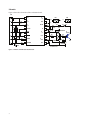
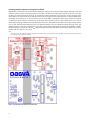
Figure 3 shows the schematics of the evaluation board.
CON1
1 µF
C3 + T A
R2
R1
10k
1 VEE1
VEE2 16
2 VIN+
VLED 15
3 VCC1
DESAT 14
4 VLEDDRV
10k
5 UVLO
CON2
6 FAULT
VOUT 11
150
7 ANODE
VCLAMP 10
150
8 CATHODE
C2
330pF
R3
R4
J2
VCC2 12
VEE2
1 µF
C7 + T A
C
R5 1k
D1
VCC2
VE
1 kV
7,8
1
R6 2W
10
VEE2
9
C5 +
1 µF
TA
R9
J1
R10
Q1b
R7 2W
0R
Q3
C
(TO247)
G
3
nm R8 47
3
PBSS4041SPN 5,6
1
Q2 nm4,2
2STN2540
nm :Not Mounted
Figure 3. Schematics of the ACPL-337J evaluation board
nm
BYV26E
Q1a nmPBSS4041SPN
2
Gnd
3
E
VE
C6
100pF
1 µF
C4 + T A
G
nm
C1
330pF
VCC2
SBD
BAT42W
VE 13
CON4
CON3
nm
Gnd
4
V EE2
nm
E
VE