1
CAN/I2C Activity Board Pro
Supported products:
Summary
The CAN/I2C Activity Board Pro is a great tool to help with embedded
systems development. This activity board provides working target
devices to aid developers in the debugging of their systems and
interface software. Target devices featured on this activity board can
operate as CAN nodes or I2C slaves. This board is compatible with
the Komodo CAN Duo interrface and the Aardvark I2C/SPI Host
Adapter.
User Manual v1.00
July 15, 2011
CAN/I2C Activity Board Pro User Manual
1 Hardware Specifications
1.1 Signaling Level/Voltage Ratings
Table 1 : Electrical Characteristics/Requirements
Parameter
Min
Max
Unit
3.1
3.5
V
Supply Input (V+)
4.3
5.5
V
Single-ended Input
-12
12
V
Differential Input
-7
7
V
Single-ended Output (Dominant) CAN+
2.9
4.5
V
CAN-
0.8
1.5
V
2
3
V
Differential Output (Dominant)
1.4
3
V
Differential Output (Recessive)
-0.5
0.05
V
4.3
5.5
V
Supplies
VDD
CAN
Single-ended Output (Recessive)
I2C
Supply Input
2
I C Inputs (Low)
-0.5 0.3*VDD
V
I2C Inputs (High)
0.7
VDD+0.5
V
I2C Outputs (Low)
0
0.4
V
GPIO Inputs (Low)
-0.5
0.8
V
GPIO Inputs (High)
2.0
5.5
V
0.7
V
GPIO Port Expander
GPIO Outputs (Low)
GPIO Outputs (High)
2.5
V
ADC
ADC Inputs
0
VDD
V
0
VDD
V
DAC
DAC Output
Notes:
• The CAN/I2C Activity Board Pro will not supply target power on the Komodo or
Aardvark header.
2
CAN/I2C Activity Board Pro User Manual
• The CAN bus is not electrically isolated from the rest of the board.
1.2 CAN Signaling Characteristics
1.2.1 Speed
The CAN/I2C Activity Board Prowill run at 125 kbps by default. If a different bitrate is
desired, set the board to auto-baud on the CAN bus through the appropriate selection
pin (see Section 2.4).
1.2.2 Known CAN Limitations
CAN Buffer Saturation
The CAN bridge includes multiple receive buffers for CAN packets. If the CAN receive
buffer overflows, then packets will be acknowledged by the node, but not processed.
The CAN bridge also includes a small number of transmit buffers for which outgoing
packets can be queued. A packet will not leave this queue until it has been successfully
transmitted. If the queue is full when the bridge attempts to write another CAN packet to
the bus, it will block until there is room in the queue.
In order to avoid either buffer saturating, no more than approximately 10 packets per
100 ms should be sent on the CAN bus.
1.3 I2C Signaling Characteristics
1.3.1 Speed
The I2C on the CAN/I2C Activity Board Pro operates at 100 kHz.
1.3.2 Pull-up Resistors
The CAN/I2C Activity Board Pro includes a 4.7 k pull-up resistor to VDD on the SCL and
SDA lines.
1.3.3 Known I2C Limitations
The CAN/I2C Activity Board Pro is not designed to work with multi-master situations. If
the board is intended to be used with other I2C masters then the I2C master functionality
3
CAN/I2C Activity Board Pro User Manual
of the CAN bridge should be inhibited. See Section 2.4 for more information on how to
do this.
1.4 Communication Protocol
It is important to understand the basics of how the CAN/I2C Activity Board Pro operates
and how the target devices communicate over both CAN and I2C. None of the targets
are CAN-compatible themselves, but the CAN/I2C Activity Board Pro features a
microcontroller which serves as a bridge between the CAN bus and the target interfaces.
This bridge allows all of the targets to operate as CAN nodes on the CAN bus. Many of
the targets are I2C devices, so they can interface directly with the Aardvark I2C/SPI Host
Adapter. The microcontroller also implements an I2C slave (0x42), which allows the LCD
display and ADC to communicate over I2C.
1.4.1 CAN
The CAN bridge simulates a number of CAN nodes by bridging each I2C device on the
CAN/I2C Activity Board Pro to the CAN bus. Each node ID is equivalent to the I2C ID
which is displayed on the silkscreen of the PCB.
The CAN/I2C Activity Board Pro follows a protocol that is similar to CANOpen. Each 11bit ID field of the CAN packet is split into a 7-bit node address and a 4-bit opcode. Two
opcodes are defined in Table 2 which can be used for standard communication with the
CAN bridge.
Table 2 : Standard CAN OpCodes
Opcode (binary) RTR Description
0000
1
Request device data
0010
0
Set device data
As an example, if we were to set the programmable LEDs on the board, then we would
send the following information on the bus:
CAN ID {OpCode : Node ID} = {0010 : 0111010} = 0x13A
RTR
False
DLC
1
Data
0x80
On the other hand, if we were to poll the Joystick for its current position, we would send
the following information on the bus:
CAN ID {OpCode : Node ID} = {0000 : 0111010} = 0x03A
RTR
True
4
CAN/I2C Activity Board Pro User Manual
DLC
1
Data
N/A
The response from the CAN bridge will then be a non-RTR packet with the same
CAN ID, and will have the appropriate data payload.
Using these Standard Opcodes provides a convenient method for getting and setting
device data, however it does not necessarily provide a means to access the full
functionality of each node. For example, this protocol does not define a method for
configuring specific pins of the GPIO port to be inputs or outputs.
In order to complete more advanced tasks on a node, it is important to remember that
each node on the CAN/I2C Activity Board Pro is in reality an I2C device, and that the
CAN bridge functions as an I2C master on this bus. The opcodes provided earlier simply
abstracted one or more I2C calls to the I2C slave in order to get or set the device data.
The following opcodes provide a mechanism for controlling the I2C master explicitly. In
each case the opcode determines the type of I2C command being sent, the node ID
would represent the I2C slave to be addressed, and the data payload would be the actual
data transmitted on the bus.
Table 3 : Extended CAN OpCodes
Opcode (binary) RTR Description
1000
1
I2C Read w/ Stop
1010
0
I2C Write w/ Stop
1100
1
I2C Read w/ No Stop
1110
0
I2C Write w/ No Stop
By following the specific I2C communication protocol for a specific sensor, the extended
CAN opcodes can be used to access any feature of the I2C device.
As an example, if we were to configure the GPIO port expander to have 4 nputs and
4 outputs, we would need to send the following command:
CAN ID {OpCode : Node ID} = {1010 : 0111010} = 0x539
RTR
False
DLC
2
Data
0x03, 0x0F
Once configured this way, the GPIO input pins could be polled or outputs set through the
standard opcode method described previously.
If instead we were to read out the current configuration of the GPIO node, we would
actually need to send two I2C commands. The first sets up the register we wish to read
with a No Stop condition, and the second reads the data out.
5
CAN/I2C Activity Board Pro User Manual
CAN ID {OpCode : Node ID} = {1110 : 0111010} = 0x739
RTR
False
DLC
1
Data
0x03
CAN ID {OpCode : Node ID} = {1000 : 0111010} = 0x439
RTR
True
DLC
1
Data
N/A
Please note that once a No Stop condition is issued to the CAN bridge, it will ignore all
standard requests until a Stop condition has been issued. Additionally, if an I2C
command is lost due to arbitration issues, it will not be retransmitted on the I2C bus.
1.4.2 I2C
The CAN/I2C Activity Board Pro uses I2C to communicate with each of the nodes on the
bus. For specifics on how to communicate with a specific node, please refer to Section 3.
1.5 CAN Bridge Interrupts
The CAN bridge is tied to the interrupt pins of the two port expander targets (See Section
3 ). Thus when one of these pins asserts, the appropriate I2C target will be polled, and
the data will be broadcast on the CAN bus.
1.6 Application Notes
1.6.1 CAN Node Errors
The CAN packet transmitted to the CAN/I2C Activity Board Pro must match one of the
defined Opcode and RTR schemes defined in Section 1.4.1. If not, then the packet will
be ignored by the CAN bridge.
Additionally, the Standard Opcodes will only be recognized for node IDs that are defined
in Table 9. The Extended Opcodes can be used with any node ID, and can thus be used
to extend to other I2C slaves that are not included on the CAN/I2C Activity Board Pro.
If there is ever an I2C error when the CAN bridge is attempting to process an RTR
packet, a response will still be sent by the bridge. However, the DLC will be 0 and the
payload will be empty.
6
CAN/I2C Activity Board Pro User Manual
1.6.2 I2C Board Configuration
The CAN bridge implements an I2C master in order to talk with the devices on the board.
However, the CAN bridge is not designed to work in multi-master situations. In order to
successfully use the CAN/I2C Activity Board Pro with an external master (such as the
Aardvark I2C/SPI Host Adapter), it is important to configure the board correctly.
To use the board with an I2C master, please configure the board in the following manner:
• Disconnect the board from any CAN bus.
• SEL0 should be left open.
• SEL1 should be left open.
• SEL2 should be jumped.
For more information on the selection pins, please refer to Section 2.4.
7
CAN/I2C Activity Board Pro User Manual
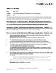
2 Connectors, Headers, Buttons, and LEDs
Figure 1 : CAN/I2C Activity Board Pro Connectors
2.1 Port Expander Header (J201)
This header allows the port expander to interface with external circuitry. See Section 3.4
for more information.
2.2 Komodo Connector (J301)
This connector is provided to interface with the Komodo CAN Interfaces. It is a male
DE-9 connector compatible with the SAE J1939 CAN-CIA standard. The pinout of this
connector is shown in Figure 2 and Table 4.
It is necessary to provide target power (4.5V-5.0V) to the CAN/I2C Activity Board Pro
through V+ on the Komodo connector, or through VDD on the Aardvark connector.
8
CAN/I2C Activity Board Pro User Manual
Figure 2 : DE-9 Connector Pin Numbers
Table 4 : Komodo Connector J301 Pinout
Pin #
Signal
1
No Connect
2
CAN-
3
GND
4
No Connect
5
No Connect
6
No Connect
7
CAN+
8
No Connect
9
V+
2.3 CAN Termination Header (J302)
This header can be jumped to connect a 120 Ohm parallel termination resistor to the
CAN bus.
2.4 Select Header (J303)
The Selection Header provides a mechanism for changing the behavior of the CAN
bridge. These pins are sampled once upon reset. To change the mode, simply place
jumpers on the appropriate selection, and hit the reset button.
Table 5 : Selection Header J303 Pinout
Signal Function
SEL0
Sets the CAN bridge to Autobaud on start-up.
SEL1
Sets the CAN bridge to broadcast all sensor data every 100 ms.
9
CAN/I2C Activity Board Pro User Manual
SEL2
Disables interrupt handling of devices on the CAN bridge.
Notes:
• If SEL0 is selected, the CAN bridge will not process any packets on CAN or I2C until a
baudrate has been selected. This can take several seconds.
• SEL1 should never be selected if the CAN/I2C Activity Board Pro is being used in I2C
mode, as it can cause multi-master arbitration errors.
• SEL2 should be selected whenever the CAN/I2C Activity Board Pro is being used in I2
C mode. This will prevent multi-master arbitration errors when interrupts occur.
2.5 Program Header (J304)
This header must be jumped to program the AT90CAN32 microcontroller.
2.6 Aardvark Connector (J401)
This connector is provided to interface with the Aardvark I2C/SPI Host Adapter. It is
necessary to provide target power (4.5 V to 5.0 V) to the CAN/I2C Activity Board Pro
through VDD on this connector, or through V+ on the Komodo connector.
This connector's pinout is listed in Table 6.
Table 6 : Aardvark Connector J401 Pinout
Pin #
Signal
1
SCL
2
GND
3
SDA
4
+5V
5
MISO
6
+5V
7
SCLK
8
MOSI
9
SS
10
GND
10
CAN/I2C Activity Board Pro User Manual
- SPI signals are for internal use only.
2.7 ADC Header (J402)
This header includes power, ground, and three analog input pins to the ADC. This
connector's pinout is listed in Table 7.
See Section 3.6 for more details about the ADC.
Table 7 : ADC Header J402 Pinout
Pin #
Signal
Function
1
VDD
3.3V
2
ADC0
Input to ADC
3
ADC1
Input to ADC
4
ADC2
Input to ADC
5
GND
Ground
6
GND
Ground
2.8 DAC Header (J403)
This header includes power, ground, and the DAC's analog output. This connector's
pinout is listed in Table 8.
See Section 3.1 for more details about the DAC.
Table 8 : DAC Header J403 Pinout
Pin #
Signal
Function
1
VDD
3.3 V
2
DAC0
Analog Output from DAC
3
GND
Ground
4
GND
Ground
2.9 Reset Button (SW301)
This button resets the CAN/I2C Activity Board Pro microcontroller and restores the
default configuration of all the peripherals.
11
CAN/I2C Activity Board Pro User Manual
2.10 Power LED (D304)
This green LED illuminates when the CAN/I2C Activity Board Pro is powered.
2.11 Activity LED (D305)
This amber LED blinks whenever the CAN/I2C Activity Board Pro is processing a CAN or
I2C packet.
12
CAN/I2C Activity Board Pro User Manual
3 Targets
Table 9 summarizes all the target devices and their CAN IDs/I2C addresses. Each node
can be accessed by I2C or CAN. In situations where the Extended CAN Opcodes are
used (see Table 3 ), follow the notes on I2C operation for that device.
Table 9 : Summary of CAN/I2C Activity Board Pro Target Devices
Target
CAN Node ID = I2C Slave Address
Digital-to-Analog Converter (DAC)
0x09
Motion Sensor
0x1D
Light Sensor
0x29
GPIO Port Expander
0x39
Joystick / LEDs
0x3A
ADC / LCD
0x42
Temperature Sensor
0x4E
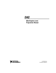
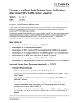
3.1 DAC (0x09)
13
CAN/I2C Activity Board Pro User Manual
Figure 3 : DAC
Part:
National Semiconductor DAC081C085
Datasheet:
http://www.national.com/profile/snip.cgi/openDS=DAC081C085
This component is a single-channel 8-bit digital-to-analog converter. It can drive its
output between 0V and VDD, with a precision of approximately 12.9 mV. It can
communicate directly over I2C, or over CAN through the bridge. Please see the
DAC081C085 datasheet for more information.
On startup, the DAC's output is set to high-impedance. Once a value is set it will be
configured to normal operation, and output the desired voltage.
3.1.1 CAN Operation
Get Sensor Data
Not applicable. This device will not respond to Get Sensor Data requests.
Set Sensor Data
To set the DAC value, a single byte needs to be transmitted with the requested DAC
setting. See Table 10.
Table 10 : CAN Set DAC Data Payload
Byte
0
Data
Notes
DAC Setting 0x00 - 0xFF representing 0 to 3.3 V
Example: Setting the DAC to approximately 1.65 V. See Table 11.
Table 11 : CAN Set DAC Data Example
Transmitter CAN ID
RTR
Komodo
False
0x109
DLC Data
1
0x80
3.1.2 I2C Operation
Please consult the DAC081C085 datasheet for details on I2C operation.
14
CAN/I2C Activity Board Pro User Manual
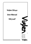
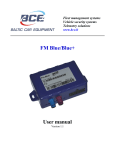
3.2 Motion Sensor (0x1D)
Figure 4 : Motion Sensor
Part:
STMicroelectronics LIS33DE
Datasheet:
www.st.com/stonline/products/literature/ds/15596/lis33de.pdf
This component is a 3-axis linear accelerometer. It can communicate directly over I2C or
over CAN through the bridge. See the PCB silkscreen for the orientation of X, Y, and Z.
Please see the devices datasheet to correlate the digital reading with the physical value.
3.2.1 CAN Operation
Get Sensor Data
The motion sensor will respond with 3 bytes of accelerometer data when a Get Sensor
Data request is made. See Table 12.
15
CAN/I2C Activity Board Pro User Manual
Getting Sensor Data is equivalent to doing a multi-byte read from the OUT_X register, as
described in the device datasheet.
Table 12 : CAN Get Motion Data Payload
Byte
Data
Notes
0
X acceleration 2's complement value
1
Y acceleration 2's complement value
2
Z acceleration 2's complement value
Example: Polling the Motion sensor. See Table 13.
Table 13 : CAN Get Motion Data Example
Transmitter
CAN ID
RTR
DLC Data
Komodo
0x01D
True
3
N/A
Activity Board
0x01D
False
3
0xAA, 0xBB, 0xCC
Set Sensor Data
Not applicable. This device will not respond to Set Sensor Data requests.
3.2.2 I2C Operation
Please consult the LIS33DE datasheet for details on I2C operation.
16
CAN/I2C Activity Board Pro User Manual
3.3 Light Sensor (0x29)
Figure 5 : Light Sensor
Part:
Avago Technologies ADPS-9300
Datasheet:
http://www.avagotech.com/docs/AV02-1077EN
This light sensor converts light intensity (irradiance) into a 16-bit digital signal. It can
communicate directly over I2C, or over CAN through the bridge. Please see the devices
datasheet to correlate the digital reading with the irradiance value.
3.3.1 CAN Operation
Get Sensor Data
The light sensor will respond with 2 bytes of irradiance value within the visible spectrum
when the Get Sensor Data request is made. See Table 14.
17
CAN/I2C Activity Board Pro User Manual
Getting Sensor Data is equivalent to reading from the Ch0 light sensor, as described in
the device datasheet.
Table 14 : CAN Get Light Data Payload
Byte
Data
Notes
0
Data0
low byte of irradiance value
1
Data1
high byte of irradiance value
Example: Polling the light sensor. See Table 15.
Table 15 : CAN Get Light Data Example
Transmitter
CAN ID
RTR
DLC Data
Komodo
0x029
True
2
N/A
Activity Board
0x029
False
2
0xAA, 0xBB
Set Sensor Data
Not applicable. This device will not respond to Set Sensor Data requests.
3.3.2 I2C Operation
Please consult the ADPS-9300 datasheet for details on I2C operation.
18
CAN/I2C Activity Board Pro User Manual
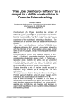
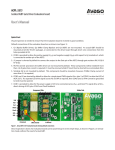
3.4 GPIO Port Expander (0x39)
Figure 6 : GPIO Port Expander
Part:
NXP Semiconductors PCA9554AD
Datasheet:
http://ics.nxp.com/products/pca/datasheet/pca9554.pca9554a.pdf
This is an 8-pin port expander which can be accessed through CAN or I2C. On start-up,
all pins are configured as inputs, and can be read over CAN. By communicating directly
with the device over I2C, it is possible to configure the pins as outputs. The port
expanders pins are connected to a header for easy access, as described in Section 2.1.
If interrupts are not disabled, changes to the inputs will cause the bridge to broadcast the
data on the CAN bus.
3.4.1 CAN Operation
Get Sensor Data
f
19
CAN/I2C Activity Board Pro User Manual
The port expander will respond with 1 byte of data describing the current value of each
input pin. See Table 16.
Getting the Sensor data is equivalent to reading from the Input Register, as described in
the device datasheet.
Table 16 : CAN Get GPIO Data Payload
Byte
0
Data
Notes
Input Value Bit mask of each input pin
Example: Polling the GPIO port expander. See Table 17.
Table 17 : CAN Get GPIO Data Example
Transmitter
CAN ID
RTR
DLC Data
Komodo
0x039
True
1
N/A
Activity Board
0x039
False
1
0xAA
Set Sensor Data
The outputs of the port expander can be set by sending 1 byte of data describing the
desired value of each output. See Table 18.
Setting the Sensor Data is equivalent to writing to the Output Register, as described in
the device datasheet.
Note that the port expander powers up as all inputs. In order to have outputs configured
the Extended Opcodes will have to be used.
Table 18 : CAN Set GPIO Data Payload
Byte
0
Data
Notes
Output Value Bit mask of desired output on each pin
Example: Setting every other output high on the GPIO port expander. See Table 19.
Table 19 : CAN Set GPIO Data Example
20
CAN/I2C Activity Board Pro User Manual
Transmitter CAN ID
RTR
Komodo
False
0x139
DLC Data
1
0xAA
3.4.2 I2C Operation
Please consult the PCA9554AD datasheet for details on I2C operation.
3.5 Joystick/LEDs (0x3A)
Figure 7 : Joystick, LEDs, and Port Expander #2
Parts:
NXP Semiconductors PCA9554AD
Datasheet:
http://ics.nxp.com/products/pca/datasheet/pca9554.pca9554a.pdf
21
CAN/I2C Activity Board Pro User Manual
The joystick and LEDs are connected to an NXP PCA9554AD port expander. The
microcontroller communicates with the joystick and LEDs through this port expander.
The joystick and LED connections to the port expander pinout are listed in Table 20.
This two-axis joystick is a very simple device. It has five output pins (up, down, left, right,
and select) which are asserted high when the joystick is moved to that position. These
outputs are then connected to an NXP I/O port expander which can communicate the
status over CAN and I2C.
There are three active high LEDs controlled by the port expander: D201, D202, and
D303. The color of these LEDs are specified in Table 20.
On startup the port expander is configured to have all joystick connections as inputs, and
all LED connections as outputs.
Table 20 : Connections to Joystick, LED, and Port Expander #2 Pinout
Port Expander Pin Direction
Connection
IO0
Input
Joystick UP
IO1
Input
Joystick RIGHT
IO2
Input
Joystick SELECT
IO3
Input
Joystick DOWN
IO4
Input
Joystick LEFT
IO5
Output
Amber LED D201
IO6
Output
Green LED D202
IO7
Output
Green LED D203
3.5.1 CAN Operation
The operation of the Joystick and LEDs is equivalent to that of the GPIO Port Expander
(Section 3.4), except that the node ID is 0x3A instead of 0x39.
3.5.2 I2C Operation
Please consult the PCA9554AD datasheet for details on I2C operation. Do not attempt to
configure pins IO0-IO4 as outputs, this can damage the CAN/I2C Activity Board Pro.
22
CAN/I2C Activity Board Pro User Manual
3.6 ADC/LCD (0x42)
Figure 8 : ADC and LCD
Part:
Internal to CAN Bridge
Datasheet:
N/A
Unlike all the other devices on the board, the ADC and LCD are not external I2C devices.
Instead, they are implemented on the MCU, and can be accessed over I2C or CAN at the
node address of 0x42.
The CAN Bridge MCU has a built-in ADC which is exposed on the PCB. The CAN/I2C
Activity Board Pro allows the user to read 3 of these analog inputs with an 8-bit
resolution. Inputs may range from 0 V to a maximum of 3.3 V.
To determine the analog input value from the received ADC data, use the following
equation:
23
CAN/I2C Activity Board Pro User Manual
The LCD is a 2x8 character display that is connected to the CAN bridge over a parallel
bus. The characters on the display are ASCII-encoded.
3.6.1 CAN Operation
Because the ADC and LCD slaves are internal to the CAN bridge, CAN communication
will not actually cause any I2C traffic to be transmitted on the bus. Whereas requests to
other nodes would cause an appropriate I2C write/read, these nodes are simply handled
internally. This is true even when using an Extended Opcode.
Get Sensor Data
The CAN Bridge will respond with 3 bytes of ADC information when the Get Sensor Data
request is made. See Table 22.
The Get Sensor Data will only get data from the ADC. It will not return any LCD
information.
Table 22 : CAN Get ADC Data Payload
Byte
Data
Notes
0
ADC Ch0 8-bit unsigned
1
ADC Ch1 8-bit unsigned
2
ADC Ch2 8-bit unsigned
Example: Polling the ADC. See Table 23.
Table 23 : CAN Get ADC Data Example
Transmitter
CAN ID
RTR
DLC Data
Komodo
0x042
True
3
N/A
Activity Board
0x042
False
3
0xAA, 0xBB, 0xCC
Set Sensor Data
The Set Sensor Data is used to set the LCD text on the screen. See Table 24.
The Set Sensor Data will only set data on the LCD. It will not set any ADC information.
24
CAN/I2C Activity Board Pro User Manual
The LCD screen is broken up into four segments of 4 characters. Each data segment is
written to individually. If not all 4 characters of a segment are included in the CAN
payload, then the remainder are filled with spaces.
Table 24 : CAN Set LCD Data Payload
Byte
Data
Notes
0
Segment Number
1
Character 0
ASCII-encoded
2
Character 1
ASCII-encoded
3
Character 2
ASCII-encoded
4
Character 3
ASCII-encoded
Example: Writing Hello World! to the LCD screen. See Table 25.
Table 25 : CAN Set LCD Data Example
Transmitter CAN ID
RTR
DLC Data
Komodo
0x142
False
5
0x00, 0x48, 0x65, 0x6c, 0x6c
Komodo
0x142
False
5
0x01, 0x6f, 0x20, 0x57, 0x6f
Komodo
0x142
False
5
0x02, 0x72, 0x6c, 0x64, 0x21
Komodo
0x142
False
2
0x03, 0x20
3.6.2 I2C Operation
Because both the ADC and LCD share a device address of 0x42, they are individually
referenced by a register address. The ADC is at register address 0x01, and the LCD is
at register address 0x02.
Setting the ADC Value
This is not applicable. Attempting to set the ADC value will do nothing.
Getting the ADC Value
Getting the ADC Value is a two step process. It requires setting up the proper register
address, and then reading back the 3 ADC values. Reading more than 3 bytes will return
0xFF for any additional bytes.
The ADC will respond with 3 bytes of data. See Table 26.
Table 26 : I2C Get ADC Data Payload
25
CAN/I2C Activity Board Pro User Manual
Byte
Data
Notes
0
ADC Ch0 8-bit unsigned
1
ADC Ch1 8-bit unsigned
2
ADC Ch2 8-bit unsigned
Example: Polling ADC sensor. See Table 27.
Table 27 : I2C Get ADC Data Example
Direction
Stop
Device ID Data
Write
No Stop
0x42
0x01
Read
Stop
0x42
0xAA, 0xBB, 0xCC
Setting the LCD Display
The LCD screen is broken up into four segments of 4 characters. Each data segment
can be written to individually.
The LCD segment will also auto-increment and wrap when operated in I2C mode.
Therefore if segment 0x00 is selected, and 8 bytes are written, then the entire first line
will be configured. No more than 16 character bytes can be written to in a single I2C
operation.
See Table 28 for a description of the data payload.
Table 28 : I2C Set LCD Data Payload
Byte
Data
Notes
0
Register Address 0x02 for LCD
1
Segment Number
2
Character 0
ASCII-encoded
...
n
Character n
ASCII-encoded
Example: Writing Hello World to the LCD screen. See Table 29.
Table 29 : I2C Set LCD Data Example
Direction Stop Device ID Data
26
CAN/I2C Activity Board Pro User Manual
Write
Stop
0x42
0x02, 0x00,
0x48, 0x65, 0x6c, 0x6c,
0x6f, 0x20, 0x57, 0x6f,
0x72, 0x6c, 0x64, 0x21,
0x20
Getting the LCD Display
Over I2C it is also possible to read out the current LCD setting. Like the ADC this
requires two steps. The first step sets up the register we wish to read from as well as the
segment to start reading from. Bytes are then read consecutively out.
See Table 30 for a description of the data payload.
Table 30 : I2C Get LCD Data Payload
Byte
Data
Notes
0
Character 0 ASCII-encoded
1
Character 1 ASCII-encoded
...
n
Character n ASCII-encoded
Example: Reading data out of LCD screen. See Table 31.
Table 31 : I2C Get LCD Data Example
27
CAN/I2C Activity Board Pro User Manual
Direction
Stop
Device ID Data
Write
No Stop
0x42
0x02, 0x00
Read
Stop
0x42
0x48, 0x65, 0x6c, 0x6c, ...
3.7 Temperature Sensor (0x4E)
Figure 9 : Temperature Sensor
Part:
Maxim Integrated Products DS75
Datasheet:
http://datasheets.maxim-ic.com/en/ds/DS75.pdf
This temperature sensor provides temperature readings over a range of -55°C to +125°
C. It can communicate directly over I2C or over CAN through the bridge.
28
CAN/I2C Activity Board Pro User Manual
3.7.1 CAN Operation
To request data from the temperature sensor over CAN, send a remote frame with an ID
of 0x4E. A CAN data frame will then be broadcast with one byte of temperature data. On
start up this device is configured for 9-bit temperature readings.
Get Sensor Data
The temperature sensor will respond with 2 bytes of temperature data when a Get
Sensor Data request is made. See Table 32.
Getting Sensor Data is equivalent to reading from the Temperature Register as
described in the device datasheet.
Table 32 : CAN Get Temperature Data Payload
Byte
Data
Notes
0
MS byte See datasheet for more information
1
LS byte
See datasheet for more information
Example: Polling the temperature sensor. See Table 33.
Table 33 : CAN Get Temperature Data Example
Transmitter
CAN ID
RTR
DLC Data
Komodo
0x04E
True
2
N/A
Activity Board
0x04E
False
2
0xAA, 0xB0
Set Sensor Data
Not applicable. This device will not respond to Set Sensor Data requests.
3.7.2 I2C Operation
Please consult the DS75 datasheet for details on I2C operation.
29
CAN/I2C Activity Board Pro User Manual
4 References
4.1 Examples
Example scripts which communicate with the target devices on the CAN/I2C Activity
Board Pro are available for download on the Total Phase website: http://
www.totalphase.com/support/product.
4.2 Technical Specifications
The CAN/I2C Activity Board Pro draws approximately 50 mA of current from the power
source, either the Komodo Interface or the Aardvark adapter.
Detailed information about the Technical Specifications of the Komodo CAN Interfaces
and the Aardvark I2C/SPI Host Adapter can be found on the Total Phase website: http://
www.totalphase.com.
30
CAN/I2C Activity Board Pro User Manual
5 Legal / Contact
5.1 Disclaimer
All of the software and documentation provided in this datasheet, is copyright Total
Phase, Inc. ("Total Phase"). License is granted to the user to freely use and distribute
the software and documentation in complete and unaltered form, provided that the
purpose is to use or evaluate Total Phase products. Distribution rights do not include
public posting or mirroring on Internet websites. Only a link to the Total Phase download
area can be provided on such public websites.
Total Phase shall in no event be liable to any party for direct, indirect, special, general,
incidental, or consequential damages arising from the use of its site, the software or
documentation downloaded from its site, or any derivative works thereof, even if Total
Phase or distributors have been advised of the possibility of such damage. The software,
its documentation, and any derivative works is provided on an "as-is" basis, and thus
comes with absolutely no warranty, either expressed or implied. This disclaimer includes,
but is not limited to, implied warranties of merchantability, fitness for any particular
purpose, and non-infringement. Total Phase and distributors have no obligation to
provide maintenance, support, or updates.
Information in this document is subject to change without notice and should not be
construed as a commitment by Total Phase. While the information contained herein is
believed to be accurate, Total Phase assumes no responsibility for any errors and/or
omissions that may appear in this document.
5.2 Life Support Equipment Policy
Total Phase products are not authorized for use in life support devices or systems. Life
support devices or systems include, but are not limited to, surgical implants, medical
systems, and other safety-critical systems in which failure of a Total Phase product could
cause personal injury or loss of life. Should a Total Phase product be used in such an
unauthorized manner, Buyer agrees to indemnify and hold harmless Total Phase, its
officers, employees, affiliates, and distributors from any and all claims arising from such
use, even if such claim alleges that Total Phase was negligent in the design or
manufacture of its product.
5.3 Contact Information
Total Phase can be found on the Internet at http://www.totalphase.com/. If you have
support-related questions, please email the product engineers at
[email protected]. For sales inquiries, please contact [email protected].
31
CAN/I2C Activity Board Pro User Manual
©2011-2011 Total Phase, Inc.
All rights reserved.
32