1
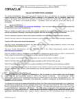
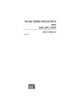
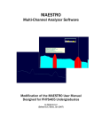
Model ASA-100
NaI MCA Board
9231906C
User’s Manual
Copyright 2001, Canberra Industries, Inc. All rights reserved.
The material in this document, including all information, pictures,
graphics and text, is the property of Canberra Industries, Inc. and
is protected by U.S. copyright laws and international copyright
conventions.
Canberra expressly grants the purchaser of this product the right
to copy any material in this document for the purchaser’s own use,
including as part of a submission to regulatory or legal authorities
pursuant to the purchaser’s legitimate business needs.
No material in this document may be copied by any third party, or
used for any commercial purpose, or for any use other than that
granted to the purchaser, without the written permission of
Canberra Industries, Inc.
Canberra Industries, 800 Research Parkway, Meriden, CT 06450
Tel: 203-238-2351 FAX: 203-235-1347 http://www.canberra.com
The information in this document describes the product as
accurately as possible, but is subject to change without notice.
Printed in the United States of America.
Table of Contents
1. Introduction . . . . . . . . . . . . . . . . . . . . . . . . . . . . . 1
2. Setup and Configuration . . . . . . . . . . . . . . . . . . . . . . 2
Installation . . . . . . . . . . . . . . . . . . . . . . . . . . . . . . . . . . . . . . . . . . . . . . 2
Installing the Card . . . . . . . . . . . . . . . . . . . . . . . . . . . . . . . . . . . . . . . . 2
Device Driver Installation . . . . . . . . . . . . . . . . . . . . . . . . . . . . . . . . . . . . 3
Installing the Software. . . . . . . . . . . . . . . . . . . . . . . . . . . . . . . . . . . . . . 3
Internal Control and Connectors . . . . . . . . . . . . . . . . . . . . . . . . . . . . . . . . . . . 4
Rear Panel Connectors . . . . . . . . . . . . . . . . . . . . . . . . . . . . . . . . . . . . . . . . 5
Creating an MCA Input Definition . . . . . . . . . . . . . . . . . . . . . . . . . . . . . . . . . 6
The MID Wizard . . . . . . . . . . . . . . . . . . . . . . . . . . . . . . . . . . . . . . . . . . . 6
The MCA Input Definition Editor . . . . . . . . . . . . . . . . . . . . . . . . . . . . . . . . . . 9
The MCA Adjust Screens . . . . . . . . . . . . . . . . . . . . . . . . . . . . . . . . . . . . . 10
The Adjustable ASA-100 Parameters . . . . . . . . . . . . . . . . . . . . . . . . . . . . . 10
Stabilizer Parameters . . . . . . . . . . . . . . . . . . . . . . . . . . . . . . . . . . . . . . 11
ADC Parameters . . . . . . . . . . . . . . . . . . . . . . . . . . . . . . . . . . . . . . . . 12
Amplifier Parameters. . . . . . . . . . . . . . . . . . . . . . . . . . . . . . . . . . . . . . 13
High Voltage Parameters. . . . . . . . . . . . . . . . . . . . . . . . . . . . . . . . . . . . 14
Acquire Setup Screen. . . . . . . . . . . . . . . . . . . . . . . . . . . . . . . . . . . . . . . . 14
A. Specifications. . . . . . . . . . . . . . . . . . . . . . . . . . . . 15
Input . . . . . . . . . . . . . . . . . . . . . . . . . . . . . . . . . . . . . . . . . . . . . . . . 15
Outputs . . . . . . . . . . . . . . . . . . . . . . . . . . . . . . . . . . . . . . . . . . . . . . . 15
Data Acquisition . . . . . . . . . . . . . . . . . . . . . . . . . . . . . . . . . . . . . . . . . . 15
ADC . . . . . . . . . . . . . . . . . . . . . . . . . . . . . . . . . . . . . . . . . . . . . . . . 15
Presets . . . . . . . . . . . . . . . . . . . . . . . . . . . . . . . . . . . . . . . . . . . . . . . 16
Preamplifier Power . . . . . . . . . . . . . . . . . . . . . . . . . . . . . . . . . . . . . . . . . 16
Amplifier . . . . . . . . . . . . . . . . . . . . . . . . . . . . . . . . . . . . . . . . . . . . . . 16
High Voltage . . . . . . . . . . . . . . . . . . . . . . . . . . . . . . . . . . . . . . . . . . . . 16
SCA . . . . . . . . . . . . . . . . . . . . . . . . . . . . . . . . . . . . . . . . . . . . . . . . . 17
Power . . . . . . . . . . . . . . . . . . . . . . . . . . . . . . . . . . . . . . . . . . . . . . . . 17
Physical . . . . . . . . . . . . . . . . . . . . . . . . . . . . . . . . . . . . . . . . . . . . . . . 17
Environmental . . . . . . . . . . . . . . . . . . . . . . . . . . . . . . . . . . . . . . . . . . . 17
Ordering Information . . . . . . . . . . . . . . . . . . . . . . . . . . . . . . . . . . . . . . . . 17
B. Installation Considerations . . . . . . . . . . . . . . . . . . . . 18
ii
1. Introduction
The ASA-100 is a fully integrated Multichannel Analyzer that contains everything
needed to support an NaI(Tl) spectroscopy system. High voltage, preamplifier power
supply, shaping amplifier, gain stabilizer, ADC, and memory are all contained in a
compact, full-length PCI-bus board. Power consumption is less than 7.5 W.
There is no need for NIM or external stand-alone electronics. Just connect the high
voltage, preamp power and signal cable to the detector, boot your computer, start the
Genie-2000 software, and you are ready to acquire spectral data. Using the ASA-100 is
easy. High voltage, amplifier coarse and fine gain, ADC conversion gain and many
other functions are easily controlled by the computer through software adjust screens.
Every ASA-100 comes equipped with its own on-board digital gain stabilizer. You’ll
never have to worry about spectrum drift again! The stabilizer continuously monitors
your system to compensate for any external variables like room temperature that can
affect peak positions.
Computer Control
This capability allows the user to maintain multiple system setups, downloading the
required configuration as needed. No manual dial adjustments are necessary. The system is ready for routine sample analysis by simply calling up predefined calibration/setup files.
Software support is available with the Genie-2000 platform, under Windows 98/Me or
Windows NT/2000. The supporting software extends the capabilities of the system to
meet a wide range of application requirements.
Setup and Configuration
2. Setup and Configuration
Unpack your ASA-100 board and examine it carefully for evidence of damage caused
in transit. If damage is found notify Canberra and the carrier immediately.
Installation
The ASA-100 is fully compliant with the Plug and Play PCI specifications and, therefore, has no hardware jumpers to be set by the user. Note that the ASA-100 is not supported for the Windows 95 operating system.
Installing the Card
The card may be installed in the target PC by using the following procedure:
1. Turn OFF the power to the computer to prevent damage to the computer and
the ASA-100 card.
2. Remove the cover from the computer. Consult the reference manual supplied
with the computer for proper instructions on removing the cover.
3. The ASA-100 may be inserted into any available full-length PCI slot.
Remove the retaining screw from the slot’s blank panel and remove the
panel.
4. To insert the ASA-100 card, the end of the card with the connectors must be
tilted downward as the card is inserted into the computer. When the
connectors have cleared the rear-panel cutout, rotate the card until it’s
parallel to and centered above the computer’s motherboard connector. Use
moderate downward pressure to seat the card in the connector.
5. Replace the retaining screw in the ASA-100 card’s rear panel and tighten.
6. Replace the computer cover by reversing the procedure in step 2.
7. Reapply power to the computer.
2
Installation
Device Driver Installation
To use the ASA-100 you must install a device driver. The device driver will be automatically installed for Windows NT with the Genie 2000 installation. For Windows
98, ME and 2000, you must install the driver, using the following procedure.
When you reboot the computer after installing the ASA-100 MCA card, Windows will
automatically launch the “Add New Hardware” Wizard. Follow the steps in the “Add
New Hardware” Wizard to add your new device driver:
1. Follow the steps that allow you to specify the location of your device driver
and click the checkbox for “specify a location”, click on “Browse” and
specify the \CIPCI\PLX\Win98_Me or \CIPCI\PLX\WinNT_2000
(depending on your operating system) directory on your CDROM.
2. Follow the steps to complete the installation of the device driver.
Note: These steps are only required once, i.e. when Windows detects that
new hardware has been added to your system or if the drivers are missing or need to be reinstalled.
Installing the Software
Refer to the Genie-2000 Operations Manual, Appendix A, “Software Installation”, for
instructions on installing the Genie-2000 Basic Spectroscopy Software.
3
Setup and Configuration
Internal Control and Connectors
This is a brief description of the internal control and connectors. For more information,
see Appendix A, Specifications.
Figure 1 Internal Control and Connectors
4
Rear Panel Connectors
Rear Panel Connectors
This is a brief description of the rear panel connectors. For more information, see Appendix A, Specifications.
Figure 2 Rear Panel Connectors
5
Setup and Configuration
Creating an MCA Input Definition
After you have installed the card and the Genie-2000 software, the first step in using
your ASA-100 board is to create an MCA Input Definition (MID).
MID Wizard or MID Editor?
For most cases, you’ll use the MID Wizard to help you set up your Input Definition
quickly and easily.
If your Input Definition is more complex than the MID Wizard was designed to handle
(i.e., multiple ASA-100 boards or other MCAs with a single PC), you’ll use the MID
Editor (page 9) to create or change your definition.
The MID Wizard
To use the MID Wizard, open the Genie-2000 folder and select the MID Wizard icon
to start the definition process.
Step 1
The first screen (Figure 3) lets you select the MCA you want to create a definition for.
Select the ASA-100 entry from the list of available MCAs.
Figure 3 Selecting the MCA
6
The MID Wizard
Step 2
The second screen (Figure 4) asks you to enter the board’s serial number. You’ll find
the eight-digit serial number engraved on the back of the board at the end opposite the
rear panel bracket (see Figure 1 on page 4.)
Figure 4 Entering the Serial Number
7
Setup and Configuration
Steps 3 and 4
You won’t see the screens for Steps 3 and 4; these steps are not used when setting up
the ASA-100.
Step 5
The next screen (Figure 5) asks you to define the high voltage power supply’s Voltage
Limit and Voltage. The Voltage Limit should be set to match the configuration of the
connected NaI detector.
Figure 5 Selecting the High Voltage Supply
8
The MCA Input Definition Editor
Step 6
The Step 6 screen (Figure 6) asks for a Detector Type and the acquisition memory
size in channels, and requires that an Input Name be entered. Select the desired memory size, based on your application’s needs.
Figure 6 Assigning the Detector Type
Ending the Definition
To complete your Input Definition, select Finish. The input that you just defined will
be stored as an MID file named inputname.MID and automatically loaded into the
Genie-2000’s MCA Runtime Configuration Database (described in “Using MCA Definition Tables” in Chapter 3, MCA Input Definition, of the Genie-2000 Operations
Manual). When you select Finish, you will be asked if you would like to define another input. Answering No will close the Wizard.
Note that if you didn’t enter an Input Name, you won’t be allowed to exit the Step 6
screen. If the name you entered is the same as the name of an existing MID file, the
system will tell you so and go back to Step 6 to let you enter another name.
The MCA Input Definition Editor
The MCA Input Definition (MID) Editor allows you to create, edit and manage input
definitions. You’ll have to use the MID Editor only if you want to change any of the
parameters from their default values. Multiple Memory Groups are selectable only
from within the MID Editor.
9
Setup and Configuration
The editing procedure is described in “Editing an MCA Definition” in the MCA Input
Definition chapter of the Genie-2000 Operations Manual. That chapter also has
detailed information on using the MID Editor.
The MCA Adjust Screens
The MCA Adjust Screens, which are accessed from the Gamma Acquisition and Analysis application’s Menu Bar, allow you to adjust the ASA-100’s programmable controls.
You may access the MCA Adjust screens after having defined an MCA Input Definition (MID) as instructed above: Start the “Gamma Acquisition and Analysis” program
contained in the Genie-2000 folder, open the ASA-100 datasource you just have defined by selecting File | Open Datasource, then selecting “Detector” in the Type box.
Next, double click on the datasource file you want to adjust.
With the datasource open, select the MCA/Adjust drop-down menu option. As adjustments are made, the new values are sent to the MCA. To save the adjustments to the
datasource’s CAM file, use the Gamma Acquisition and Analysis application’s
File | Save command so that the next time this datasource is selected, the proper setting will be loaded into the MCA.
Note: If you get a “Required Hardware Unavailable” error, possible causes
are: selecting the wrong datasource for the instrument or a serial number mismatch between the ASA-100 and the MID setting.
If you get a “Hardware Verification Error”, there is a mismatch between
the MID Definition setup and the hardware configuration. You can
choose to accept or not accept the verification error in the associated
dialog box. If you select No, a RED error box will appear in the top left
corner of the Gamma Acquisition and Analysis window. To determine
the source of the verification error, open the Status Page by clicking
MCA | Status in the Acquisition and Analysis window. The problem
item will be marked with an asterisk (*).
The Adjustable ASA-100 Parameters
Each of the following sections describes the ASA-100 parameters that can be changed
in the Gamma Acquisition and Analysis (GAA) application Adjust dialog. To change a
parameter, click on MCA | Adjust in the GAA application’s Main Menu, then select
the radio button for the parameter you want to change.
10
The MCA Adjust Screens
Stabilizer Parameters
The controls in the Stabilizer settings screen (Figure 8) for the ASA-100 are described
in the following paragraphs.
Figure 8 Stabilizer Setting Adjust Dialog
Figure 7 shows the relationship between the Stabilizer’s Centroid and Spacing on a
typical peak for Gain Stabilization. For a detailed explanation of how a Stabilizer is
used, refer to the “Stabilizer” section of Chapter 4, Gamma Acquisition and Analysis,
in the Genie-2000 Operations Manual.
Figure 7 Relationship Between Stabilizer Functions
11
Setup and Configuration
Gain Centroid
Sets the centroid (in channels) of the reference peak at the high end of the spectrum for
gain stabilization.
Gain Spacing
Sets the spacing (in channels) between the upper and lower sampling channels. The
sampling channels should be placed so that a shift in the reference peak reflects a significant change in count rate in the sampling channels. For broad peaks, the spacing
should be set so that the sampling channels are not on the flat part of the peak.
Gain Mode
Enables (On) or disables (Off) the Gain Stabilization function.
ADC Parameters
Click on the ADC button to see the dialog box in Figure 9, which shows the Adjust
screen for the analog-to-digital converter.
Figure 9 ADC Adjust Dialog
Conversion Gain
There is no setting for Conversion Gain in the ADC adjustment screen. The number of
channels in the spectrum is selected by adjusting the Input Size scroll bar in the Acquire Setup screen (page 14).
Note: When using Multiple Memory Groups the input memory size must be
adjusted using the MID editor, not the Input Size setting.
Lower Level Discriminator
The LLD scroll bar sets the minimum pulse height that will be converted by the ADC.
Noise and background events that dominate the lower channels can be suppressed by
moving the scroll bar to the right.
12
The MCA Adjust Screens
Upper Level Discriminator
The ULD scroll bar sets the maximum pulse height that will be converted by the ADC.
For most work, this control will be set to 100 percent. Lower settings will inhibit data
acquisition in the upper channels.
ADC Zero
In most cases, channel one of the spectrum is made to correspond to a zero energy input (zero intercept). This means that the location of a given event in the spectrum is
linearly and directly proportional to the height of the input pulse. In some cases, however, the Zero control can be used to offset the spectrum by up to –1.5% to +4.5% of
the ADC’s current conversion gain.
The ADC Zero control will not normally have to be adjusted, but should it become
necessary, remove the computer’s top cover and look for the control on the top edge of
the board, as shown in Figure 1 (on page 4).
Amplifier Parameters
Click on the Amp button to see the dialog box in Figure 10, which shows the adjust
screen for the programmable amplifier.
Figure 10 Amplifier Adjust Dialog
Coarse Gain
The Amplifier’s Coarse gain setting is selected from the drop down menu. For most
configurations, it’s best to choose the highest Coarse Gain which, combined with the
Fine Gain, will produce the total desired gain.
Fine Gain
The Fine Gain control is set with the scroll bar.
Input Mode
The signal from the input connector may be routed through the amplifier (most common) or directly to the ASA-100’s ADC section for use with an external shaping amplifier.
13
Setup and Configuration
High Voltage Parameters
Click on the HVPS button to see the HVPS adjust screen (Figure 11).
Figure 11 High Voltage Adjust Dialog
Voltage
The Voltage scroll bar sets the output of the HVPS between the minimum and maximum settings of the Voltage Limit control set in the MID Editor. The voltage can also
be typed in from the keyboard, then accepted with the OK button.
Status
Enables (On) or disables (Off) the High Voltage Power Supply.
Acquire Setup Screen
The Gamma Acquisition and Analysis application’s Acquire Setup Screen, which allows you to define default acquisition parameters to be used when starting data collection on hardware datasources, is described in detail in the “MCA Menu” section of the
“Gamma Acquisition and Analysis” chapter of the Genie-2000 Operations Manual.
14
Input
A. Specifications
Input
SIG IN – Accepts output of a detector preamplifier or an external shaping amplifier,
software selectable; ±12 V max.; In ≈ 100 kΩ; rear panel BNC connector.
Outputs
H.V. OUT – Supplies high voltage to a NaI detector; 0–1000 V; 0–1 mA; rear panel
SHV connector.
PRE PWR – Provides power to a detector preamplifier; rear panel DB-9 connector.
Data Acquisition
CHANNELS – 2048; configurable as two 1024 channel groups, four 512 channel
groups or eight 256 channel groups.
ADC
TYPE – 80 MHz Wilkinson; 1024 channels.
INTEGRAL NONLINEARITY – <±0.1% over top 98% of channels.
DIFFERENTIAL NONLINEARITY – <±2% over top 98% of channels.
GAIN DRIFT – <±200 ppm/°C.
ZERO DRIFT – <±50 ppm/°C, full scale.
LIVE TIME CLOCK RESOLUTION – 10 ms.
INPUT – Positive-going unipolar Gaussian or bipolar, positive lobe leading pulse; 8 V,
full scale.
15
Specifications
Presets
REAL TIME – <9 999 999 seconds.
LIVE TIME – <9 999 999 seconds.
PEAK COUNTS – <9 999 999 counts.
ROI INTEGRAL – <9 999 999 counts.
Preamplifier Power
+12 V (±5%) – 50 mA
–12 V (±5%) – 50 mA
Amplifier
SHAPING – Bipolar; 1.0 µs time constant.
POLE/ZERO – Optimized for 50 µs decay time constant.
COARSE GAIN – x4, x8, …, x256; computer selectable.
FINE GAIN – x1.00, x1.10, …, x2.50; computer selectable.
GAIN STABILIZER – Range: ±12.5%; resolution: 1/4 channel.
INPUT – Positive-going tail pulse; 5 V full scale at minimum gain.
High Voltage
RANGE – From 0 to +1000 V.
CURRENT – From 0 to 1 mA.
NOISE – Less than 50 mV peak-to-peak.
TEMPERATURE COEFFICIENT – <±100 ppm/°C.
16
SCA
SCA
LLD – Software controlled; range: 0–100%, full scale.
ULD – Software controlled; range: 0–100%, full scale.
ZERO – Board mounted screwdriver-adjustable potentiometer; range: –1.5% to
+4.5%, full scale.
Power
+5 V, 1500 mA at full preamp and HV load.
Physical
BOARD TYPE – Full length PCI-compatible plug-in card.
SIZE – 31.2 x 10.7 cm (12.28 x 4.2 in.).
Environmental
OPERATING TEMPERATURE – 0 to 50 °C.
OPERATING HUMIDITY – 0–80% relative, non-condensing.
Ordering Information
Model ASA-100 NaI Multichannel Analyzer Board.
Requires Genie-2000 Basic Spectroscopy Software (S502C or S500C).
17
Installation Considerations
B. Installation Considerations
This unit complies with all applicable European Union requirements.
Compliance testing was performed with application configurations commonly used for
this module; i.e. a CE compliant NIM Bin and Power Supply with additional CE compliant application-specific NIM were used with a CE-compliant computer.
During the design and assembly of the module, reasonable precautions were taken by
the manufacturer to minimize the effects of RFI and EMC on the system. However,
care should be taken to maintain full compliance. These considerations include:
• A CE-compliant computer, fully closed on all sides with rear panel access
• Single point external cable access
• Blank panels to cover open rear panel board slots
• The use of CE compliant accessories such as fans, UPS, etc.
• Compliant grounding and safety precautions for any accessories
Any repairs or maintenance should be performed by a qualified Canberra service
representative. Failure to use exact replacement components, or failure to reassemble
the unit as delivered, may affect the unit’s compliance with the specified EU
requirements.
18
Canberra (we, us, our) warrants to the customer (you, your) that for a period of ninety (90) days from the date of
shipment, software provided by us in connection with equipment manufactured by us shall operate in accordance
with applicable specifications when used with equipment manufactured by us and that the media on which the
software is provided shall be free from defects. We also warrant that (A) equipment manufactured by us shall be
free from defects in materials and workmanship for a period of one (1) year from the date of shipment of such
equipment, and (B) services performed by us in connection with such equipment, such as site supervision and
installation services relating to the equipment, shall be free from defects for a period of one (1) year from the date of
performance of such services.
If defects in materials or workmanship are discovered within the applicable warranty period as set forth above, we
shall, at our option and cost, (A) in the case of defective software or equipment, either repair or replace the
software or equipment, or (B) in the case of defective services, reperform such services.
LIMITATIONS
EXCEPT AS SET FORTH HEREIN, NO OTHER WARRANTIES OR REMEDIES, WHETHER STATUTORY,
WRITTEN, ORAL, EXPRESSED, IMPLIED (INCLUDING WITHOUT LIMITATION, THE WARRANTIES OF
MERCHANTABILITY OR FITNESS FOR A PARTICULAR PURPOSE) OR OTHERWISE, SHALL APPLY. IN NO
EVENT SHALL CANBERRA HAVE ANY LIABILITY FOR ANY SPECIAL, EXEMPLARY, PUNITIVE, INDIRECT
OR CONSEQUENTIAL LOSSES OR DAMAGES OF ANY NATURE WHATSOEVER, WHETHER AS A RESULT
OF BREACH OF CONTRACT, TORT LIABILITY (INCLUDING NEGLIGENCE), STRICT LIABILITY OR
OTHERWISE. REPAIR OR REPLACEMENT OF THE SOFTWARE OR EQUIPMENT DURING THE
APPLICABLE WARRANTY PERIOD AT CANBERRA'S COST, OR, IN THE CASE OF DEFECTIVE SERVICES,
REPERFORMANCE AT CANBERRA'S COST, IS YOUR SOLE AND EXCLUSIVE REMEDY UNDER THIS
WARRANTY.
EXCLUSIONS
Our warranty does not cover damage to equipment which has been altered or modified without our written
permission or damage which has been caused by abuse, misuse, accident, neglect or unusual physical or
electrical stress, as determined by our Service Personnel.
We are under no obligation to provide warranty service if adjustment or repair is required because of damage
caused by other than ordinary use or if the equipment is serviced or repaired, or if an attempt is made to service or
repair the equipment, by other than our Service Personnel without our prior approval.
Our warranty does not cover detector damage due to neutrons or heavy charged particles. Failure of beryllium,
carbon composite, or polymer windows, or of windowless detectors caused by physical or chemical damage from
the environment is not covered by warranty.
We are not responsible for damage sustained in transit. You should examine shipments upon receipt for evidence
of damage caused in transit. If damage is found, notify us and the carrier immediately. Keep all packages,
materials and documents, including the freight bill, invoice and packing list.
When purchasing our software, you have purchased a license to use the software, not the software itself. Because
title to the software remains with us, you may not sell, distribute or otherwise transfer the software. This license
allows you to use the software on only one computer at a time. You must get our written permission for any
exception to this limited license.
BACKUP COPIES
Our software is protected by United States Copyright Law and by International Copyright Treaties. You have our
express permission to make one archival copy of the software for backup protection. You may not copy our
software or any part of it for any other purpose.
Revised 1 Apr 03