Download 78K0R - Say it! - Renesas Electronics
Transcript
User’s Manual 78K0R - Say it! Demonstration Kit for the 78K0R 16-bit microcontroller family Document No. U19237EE1V0UM00 Date Published June 2008 NEC Electronics (Europe) GmbH 78K0R - Say it! • The information in this document is current as of June, 2008. The information is subject to change without notice. For actual design-in, refer to the latest publications of NEC Electronics data sheets or data books, etc., for the most up-to-date specifications of NEC Electronics products. Not all products and/or types are available in every country. Please check with an NEC Electronics sales representative for availability and additional information. • No part of this document may be copied or reproduced in any form or by any means without the prior written consent of NEC Electronics. NEC Electronics assumes no responsibility for any errors that may appear in this document. • NEC Electronics does not assume any liability for infringement of patents, copyrights or other intellectual property rights of third parties by or arising from the use of NEC Electronics products listed in this document or any other liability arising from the use of such products. No license, express, implied or otherwise, is granted under any patents, copyrights or other intellectual property rights of NEC Electronics or others. • Descriptions of circuits, software and other related information in this document are provided for illustrative purposes in semiconductor product operation and application examples. The incorporation of these circuits, software and information in the design of a customer's equipment shall be done under the full responsibility of the customer. NEC Electronics assumes no responsibility for any losses incurred by customers or third parties arising from the use of these circuits, software and information. • While NEC Electronics endeavors to enhance the quality, reliability and safety of NEC Electronics products, customers agree and acknowledge that the possibility of defects thereof cannot be eliminated entirely. To minimize risks of damage to property or injury (including death) to persons arising from defects in NEC Electronics products, customers must incorporate sufficient safety measures in their design, such as redundancy, fire-containment and anti-failure features. • NEC Electronics products are classified into the following three quality grades: "Standard", "Special" and "Specific". The "Specific" quality grade applies only to NEC Electronics products developed based on a customerdesignated "quality assurance program" for a specific application. The recommended applications of an NEC Electronics product depend on its quality grade, as indicated below. Customers must check the quality grade of each NEC Electronics product before using it in a particular application. "Standard": Computers, office equipment, communications equipment, test and measurement equipment, audio and visual equipment, home electronic appliances, machine tools, personal electronic equipment and industrial robots. "Special": Transportation equipment (automobiles, trains, ships, etc.), traffic control systems, anti-disaster systems, anti-crime systems, safety equipment and medical equipment (not specifically designed for life support). "Specific": Aircraft, aerospace equipment, submersible repeaters, nuclear reactor control systems, life support systems and medical equipment for life support, etc. The quality grade of NEC Electronics products is "Standard" unless otherwise expressly specified in NEC Electronics data sheets or data books, etc. If customers wish to use NEC Electronics products in applications not intended by NEC Electronics, they must contact an NEC Electronics sales representative in advance to determine NEC Electronics' willingness to support a given application. (Note) (1) "NEC Electronics" as used in this statement means NEC Electronics Corporation and also includes its majority-owned subsidiaries. (2) "NEC Electronics products" means any product developed or manufactured by or for NEC Electronics (as defined above). M8E 02. 11-1 User’s Manual U19237EE1V0UM00 2 78K0R - Say it! CAUTION This is a Test- and Measurement equipment with possibility to be significantly altered by user through hardware enhancements/modifications and/or test or application software. Thus, with respect to Council Directive 89/336/EEC (Directive on compliance with the EMC protection requirements), this equipment has no autonomous function. Consequently this equipment is not marked by the CE-symbol. EEDT-ST-005-10 CAUTION This equipment should be handled like a CMOS semiconductor device. The user must take all precautions to avoid build-up of static electricity while working with this equipment. All test and measurement tool including the workbench must be grounded. The user/operator must be grounded using the wrist strap. The connectors and/or device pins should not be touched with bare hands. EEDT-ST-004-10 For customers in the European Union only Redemption of Waste Electrical and Electronic Equipment (WEEE) in accordance with legal regulations applicable in the European Union only: This equipment (including all accessories) is not intended for household use. After use the equipment cannot be disposed of as household waste. NEC Electronics (Europe) GmbH offers to take back the equipment. All you need to do is register at http://www.eu.necel.com/weee User’s Manual U19237EE1V0UM00 3 78K0R - Say it! Regional Information Some information contained in this document may vary from country to country. Before using any NEC product in your application, please contact the NEC office in your country to obtain a list of authorized representatives and distributors. They will verify: • • • • • • Device availability Ordering information Product release schedule Availability of related technical literature Development environment specifications (for example, specifications for third-party tools and components, host computers, power plugs, AC supply voltages, and so forth) Network requirements In addition, trademarks, registered trademarks, export restrictions, and other legal issues may also vary from country to country. NEC Electronics Inc. (U.S.) Santa Clara, California Tel: 408-588-6000 800-366-9782 Fax: 408-588-6130 800-729-9288 NEC Electronics Hong Kong Ltd. Hong Kong Tel: 2886-9318 Fax: 2886-9022/9044 NEC Electronics (Europe) GmbH Duesseldorf, Germany Tel: 0211-65 03 0 Fax: 0211-65 03 1327 NEC Electronics Hong Kong Ltd. Seoul Branch Seoul, Korea Tel: 02-528-0303 Fax: 02-528-4411 Sucursal en España Madrid, Spain Tel: 091- 504 27 87 Fax: 091- 504 28 60 NEC Electronics Singapore Pte. Ltd. Singapore Tel: 65-6253-8311 Fax: 65-6250-3583 Succursale Française Vélizy-Villacoublay, France Tel: 01-30-67 58 00 Fax: 01-30-67 58 99 NEC Electronics Taiwan Ltd. Taipei, Taiwan Tel: 02-2719-2377 Fax: 02-2719-5951 Filiale Italiana Milano, Italy Tel: 02-66 75 41 Fax: 02-66 75 42 99 NEC do Brasil S.A. Electron Devices Division Guarulhos, Brasil Tel: 55-11-6465-6810 Fax: 55-11-6465-6829 Branch The Netherlands Eindhoven, The Netherlands Tel: 040-244 58 45 Fax: 040-244 45 80 Branch Sweden Taeby, Sweden Tel: 08-63 80 820 Fax: 08-63 80 388 United Kingdom Branch Milton Keynes, UK Tel: 01908-691-133 Fax: 01908-670-290 User’s Manual U19237EE1V0UM00 4 78K0R - Say it! Revision History Date 17-06-2008 Revision V1.00 Chapter --- Description First release User’s Manual U19237EE1V0UM00 5 78K0R - Say it! Table of Contents 1. Introduction......................................................................................................................11 1.1 1.2 1.3 1.4 Main features of 78K0R – Say it!.................................................................................................... 11 System requirements...................................................................................................................... 12 Package contents............................................................................................................................ 12 Trademarks ...................................................................................................................................... 12 2. 78K0R - Say it! system configuration .............................................................................13 2.1 2.2 2.3 78K0R - Say it! ................................................................................................................................. 13 Host computer ................................................................................................................................. 13 Power supply via USB interface .................................................................................................... 13 3. 78K0R - Say it! components............................................................................................14 3.1 3.2 3.3 3.4 3.5 3.5.1 3.5.2 3.5.3 3.6 3.7 3.8 3.9 3.10 3.11 3.12 3.13 3.14 3.15 3.16 3.17 SW1, Navigation switch .................................................................................................................. 15 SW2, Switch (INTP0) ....................................................................................................................... 15 SW3, Switch (INTP1) ....................................................................................................................... 15 SW4, Switch (Filter)......................................................................................................................... 16 SW5, Configuration switch............................................................................................................. 16 SW5 bits1-5, On-Board debug mode (TK-78K0R debugging) ....................................................... 16 SW5 bits1-5, Stand alone mode .................................................................................................... 17 SW5 bits6-8, General purpose switches ........................................................................................ 17 SW6, RESET button ........................................................................................................................ 18 JP1, Power Supply selector ........................................................................................................... 18 JP2, External power connector...................................................................................................... 18 Photo-IC illuminance sensor, Q1 ................................................................................................... 18 LED1~16, general purpose LEDs ................................................................................................. 19 LED17, power LED ........................................................................................................................ 19 CN1, AC power supply connector ............................................................................................... 19 CN2, external speaker jack........................................................................................................... 20 FP1, MINICUBE2 / PG-FP4 connector ......................................................................................... 20 USB1, serial interface connector ................................................................................................. 21 Wrap field ....................................................................................................................................... 21 T1~T100, test pads ........................................................................................................................ 22 4. On-Chip debugging .........................................................................................................24 4.1 4.2 OCD via TK-78K0R On-Board debug function ............................................................................. 24 OCD via QB-MINI2 emulator........................................................................................................... 25 5. 78K0R/KG3 memory map ................................................................................................26 6. 78K0R – Say it! installation and operation.....................................................................27 6.1 Getting started................................................................................................................................. 27 6.1.1 CD-ROM contents .......................................................................................................................... 27 7. Hardware installation.......................................................................................................28 User’s Manual U19237EE1V0UM00 6 78K0R - Say it! 8. Software installation........................................................................................................28 8.1 8.2 8.3 8.3.1 8.3.2 8.4 IAR Systems Embedded Workbench for 78K installation ........................................................... 28 Sample program installation .......................................................................................................... 28 USB Driver Installation ................................................................................................................... 29 Installation on Windows 2000......................................................................................................... 29 Installation on Windows XP............................................................................................................ 34 Confirmation of USB Driver Installation ....................................................................................... 38 9. IAR sample session .........................................................................................................39 10. Troubleshooting.............................................................................................................43 11. Sample programs...........................................................................................................45 11.1 General Introduction ..................................................................................................................... 45 11.2 “78K0R_Sayit_VoiceDemo_Obj” sample program .................................................................... 46 11.2.1 How to run the sample program ................................................................................................... 48 11.2.2 Sound Play Function .................................................................................................................... 48 11.2.3 Illuminance Sensor Function ........................................................................................................ 51 11.2.4 Beep Play Function ...................................................................................................................... 53 11.3 “78K0R_Sayit_VoiceDemo_Src” sample program..................................................................... 55 11.4 “78K0R_Sayit_DownloadDemo” sample program..................................................................... 58 11.4.1 Procedure to change sound data by downloading via CvADPCM tool......................................... 59 11.5 “78K0R_Sayit_VoiceDemo” source code description............................................................... 60 11.5.1 Example of Creating Sound Play Application ............................................................................... 61 11.5.1.1 Initialize...................................................................................................................................... 61 11.5.1.2 Wait for user input ..................................................................................................................... 62 11.5.1.3 Pre-process for sound data ....................................................................................................... 63 11.5.1.4 Process to play sound ............................................................................................................... 64 11.5.2 Decode Process API .................................................................................................................... 65 11.5.2.1 Initialization of Decode Process API.......................................................................................... 65 11.5.2.2 32Kbps Decompression API ..................................................................................................... 65 11.5.2.3 24Kbps Decompression API ..................................................................................................... 65 11.5.2.4 16Kbps Decompression API ..................................................................................................... 65 11.5.3 Format of Decompressed Data .................................................................................................... 65 11.5.4 Output Cycle and Interruption....................................................................................................... 66 11.5.5 Decode 32Kbps Compressed Data.............................................................................................. 67 11.5.6 Sound Output Process (62.5µs Interrupt) .................................................................................... 69 11.5.7 Example of A/D Conversion ......................................................................................................... 75 11.6 Function Specifications................................................................................................................ 76 11.6.1 void main( void ) ........................................................................................................................... 76 11.6.2 void vVoice_main( void ) .............................................................................................................. 76 11.6.3 void vCPUinitialize( void ) ............................................................................................................. 76 11.6.4 void vPlayPrmInitialize( void )....................................................................................................... 76 11.6.5 void vAdpcmPrmInitialize( void ) .................................................................................................. 77 11.6.6 void vKeyMon_Standby( U8 *p_mode , U8 *p_num , U8 *p_volume )......................................... 77 11.6.7 void vKeyMon_Play( U8* p_volume ) ........................................................................................... 77 11.6.8 void vVolumeLED( U8 lvl )............................................................................................................ 77 11.6.9 void vModeLED( U8 mode ) ......................................................................................................... 78 11.6.10 void vPlayNumLED( U8 num ) ................................................................................................... 78 11.6.11 void vVolumeControl( U8 lvl ) ..................................................................................................... 78 11.6.12 void vDecode_32k( U8 p_mode , U8 *p_volume , U32 size , U8 __far * adr )........................... 79 11.6.13 void vDecode_24k( U8 p_mode , U8 *p_volume , U32 size , U8 __far * adr )........................... 79 11.6.14 void vDecode_16k( U8 p_mode , U8 *p_volume , U32 size , U8 __far * adr )........................... 80 11.6.15 void vLoadAdpcmData( void ) .................................................................................................... 80 User’s Manual U19237EE1V0UM00 7 78K0R - Say it! 11.6.16 void vINTTM04_hdr( void )......................................................................................................... 81 11.6.17 void vINTTM05_hdr( void )......................................................................................................... 81 11.6.18 void vBeep_sample( void ) ......................................................................................................... 81 11.6.19 void vAD_main( void ) ................................................................................................................ 81 11.6.20 void vSilence( U32 msec , U8 p_mode ) .................................................................................... 82 11.6.21 void vBeep( U8 p_mode , U8 tone , U32 msec )........................................................................ 82 11.6.22 U32 uiADconvert( void ) ............................................................................................................. 82 11.7 Macro Specifications .................................................................................................................... 83 11.7.1 START_PWM() ............................................................................................................................ 83 11.7.2 STOP_PWM() .............................................................................................................................. 83 11.7.3 START_DA_A()............................................................................................................................ 83 11.7.4 STOP_DA_A().............................................................................................................................. 83 11.7.5 START_625() ............................................................................................................................... 84 11.7.6 STOP_625() ................................................................................................................................. 84 11.7.7 DA_LED( x ) ................................................................................................................................. 84 11.7.8 PWM_LED( x ) ............................................................................................................................. 84 11.7.9 PLAY_LED( x ) ............................................................................................................................. 85 11.7.10 PLAY1_LED( x ) ......................................................................................................................... 85 11.7.11 PLAY2_LED( x ) ......................................................................................................................... 85 11.7.12 PLAY3_LED( x ) ......................................................................................................................... 85 11.7.13 PLAY4_LED( x ) ......................................................................................................................... 86 11.7.14 VLM_LED( x ) ............................................................................................................................. 86 11.7.15 DIPSW() ..................................................................................................................................... 86 11.7.16 JOYSTK() ................................................................................................................................... 86 11.8 Variable/Constant Specifications ................................................................................................ 87 11.8.1 Adpcm_Work[16].......................................................................................................................... 87 11.8.2 output_data[2]............................................................................................................................... 87 11.8.3 output_count................................................................................................................................. 87 11.8.4 ucPlaySts...................................................................................................................................... 87 11.8.5 stop_Led....................................................................................................................................... 88 11.8.6 PlayMode...................................................................................................................................... 88 11.8.7 uiIntCounter1 ................................................................................................................................ 88 11.8.8 uiIntCounter2 ................................................................................................................................ 88 11.8.9 usKeyStsCount[5]......................................................................................................................... 89 11.8.10 ucKeyStsLocked[5]..................................................................................................................... 89 11.8.11 voice_adpcm[4] .......................................................................................................................... 90 11.8.12 ucAmpLevelTable[9]................................................................................................................... 90 11.8.13 ucVolumeLevelLEDTable[9]....................................................................................................... 91 12. Cables .............................................................................................................................92 12.1 USB interface cable (Mini-B type)................................................................................................ 92 13. Schematics.....................................................................................................................93 User’s Manual U19237EE1V0UM00 8 78K0R - Say it! List of Figures Figure 1: 78K0R - Say it! system configuration ...........................................................................................13 Figure 2: 78K0R - Say it! board connectors and switches...........................................................................14 Figure 3: Navigation switch SW1.................................................................................................................15 Figure 4: Switch SW4, Filter / Amplifier circuit.............................................................................................16 Figure 5: USB1, USB Mini-B Type Host Connector Pin Configuration ........................................................21 Figure 6: Test pads, T1~T100 .....................................................................................................................22 Figure 7: On-Chip debugging ......................................................................................................................24 Figure 8: 78K0R/KG3 memory map ............................................................................................................26 Figure 9: Found New Hardware Wizard (Windows 2000) ...........................................................................29 Figure 10: Search Method (Windows 2000) ................................................................................................30 Figure 11: Driver File Location (Windows 2000) .........................................................................................30 Figure 12: Address Specification 1 (Windows 2000)...................................................................................31 Figure 13: Address Specification 2 (Windows 2000)...................................................................................31 Figure 14: Address Specification 3 (Windows 2000)...................................................................................32 Figure 15: Driver File Search (Windows 2000)............................................................................................32 Figure 16: USB Driver Installation Completion (Windows 2000) .................................................................33 Figure 17: Found New Hardware Wizard 1 (Windows XP) .........................................................................34 Figure 18: Found New Hardware Wizard 2 (Windows XP) .........................................................................34 Figure 19: Search Location Specification 1 (Windows XP) .........................................................................35 Figure 20: Search Location Specification 2 (Windows XP) .........................................................................35 Figure 21: Search Location Specification 3 (Windows XP) .........................................................................36 Figure 22: Windows XP Logo Testing (Windows XP) .................................................................................36 Figure 23: USB Driver Installation Completion (Windows XP) ....................................................................37 Figure 24: Device Manager .........................................................................................................................38 Figure 25: IAR Embedded Workbench........................................................................................................39 Figure 26: IAR project workspace ...............................................................................................................40 Figure 27: IAR debugger options.................................................................................................................40 Figure 28: IAR Linker options ......................................................................................................................41 Figure 29: TK-78 hardware setup menu......................................................................................................41 Figure 30: IAR project download .................................................................................................................42 Figure 31: IAR C-SPY debugger .................................................................................................................43 Figure 32: TK-78 enter Hardware Setup......................................................................................................44 Figure 33: TK-78 Hardware Setup menu.....................................................................................................44 Figure 34: TK-78 flash erasing ....................................................................................................................44 Figure 35: USB interface cable (Mini-B type) ..............................................................................................92 Figure 36: 78K0R - Say it! schematics 1/3 ..................................................................................................93 Figure 37: 78K0R - Say it! schematics 2/3 ..................................................................................................94 Figure 38: 78K0R - Say it! schematics 3/3 ..................................................................................................95 User’s Manual U19237EE1V0UM00 9 78K0R - Say it! List of Tables Table 1: On-Board debug mode setting, switch SW5 .................................................................................16 Table 2: Stand alone mode setting, switch SW5 .........................................................................................17 Table 3: General purpose switches, switch SW5 ........................................................................................17 Table 4: Power supply selector, JP1 ...........................................................................................................18 Table 5: External power connector, JP2......................................................................................................18 Table 6: General purpose LEDs, LED1~16 .................................................................................................19 Table 7: External speaker jack CN2 ............................................................................................................20 Table 8: PG-FP4 / QB-MINI2 connector FP1 ..............................................................................................20 Table 9: Configuration of SW5 bits1-5 when using PG-FP4 or QB-MINI2 ..................................................20 Table 10: Pin Configuration of Connector USB1 .........................................................................................21 Table 11: Test pads, T1~T100 ....................................................................................................................23 Table 12: OCD via TK-78K0R On-Board debug function ............................................................................24 Table 13: OCD via QB-MINI2 emulator .......................................................................................................25 Table 14: 78K0R - Say it! CD-ROM directory structure ...............................................................................27 Table 15: Example directory structure .........................................................................................................45 User’s Manual U19237EE1V0UM00 10 78K0R - Say it! 1. Introduction 78K0R - Say it! is a demonstration kit for the NEC 78K0R 16-bit microcontroller family. It allows the development of an sound system based on the 78K0R/KG3 device. It supports onboard debugging and real time execution of application programs. The board is prepared to be connected to user hardware parts such as digital I/O or analog signals. 1.1 Main features of 78K0R – Say it! • Easy to use device demonstration capabilities 78K0R - Say it! contains elements to easily demonstrate simple I/O-functions, i.e. navigator switch, a photo-IC illuminance sensor, I/O lines, analog inputs and outputs, UART serial interface etc. • On-Board debug function (TK-78K0R debugging) The 78K0R – Say it! supports an On-Board debug function by using the IAR C-SPY debugger without a need of additional debug hardware. It allows FLASH downloading and standard debug functions like code execution, single stepping, breakpoints, memory manipulation etc. • Audio parts The 78K0R - Say it! provides an audio filter, amplifier, onboard speaker and additional a loudspeaker connector to build up sound systems based on the 78K0R/KG3 device. • Power supply by USB interface • Analog to digital signal conversion • Digital to analog signal conversion • Various input / output signals available, such as ° ° ° ° ° ° ° I/O ports prepared to be connected to user hardware Timer input / output signals Two or three wire serial I/O Virtual UART interface, via the µPD78F0731 78K0 8-bit microcontroller with on-board USB interface 16 analog input lines 2 analog output lines Navigation switch prepared for key interrupt generation • The IAR Embedded Workbench for 78K and the IAR C-SPY debugger / simulator are included. These packages are restricted in such that maximum program code size is limited to 16 kByte. • Full documentation is included for the NEC 78K0R/KG3 microcontroller, IAR Systems Embedded Workbench and IAR Systems C-SPY debugger / simulator. 78K0R – Say it! is not intended for code development. NEC does not allow and does not support in any way any attempt to use 78K0R - Say it! in a commercial or technical product. User’s Manual U19237EE1V0UM00 11 78K0R - Say it! 1.2 System requirements HOST PC Host interface A PC supporting Windows 2000 or Windows XP is required for the IAR Systems Embedded Workbench demo-version. A Pentium processor with at least 1 GHz CPU performance, with at least 256 Mbytes of RAM, allowing you to fully utilize and take advantage of the product features. 500 Mbytes of free disk space, and an additional 10 Mbytes of free disk space on the Windows system drive. A web browser and Adobe Acrobat Reader to be able to access all the product documentation. USB interface that enables communication based on USB (Ver1.1 or later) 1.3 Package contents Please verify that you have received all parts listed in the package contents list attached to the 78K0R - Say it! package. If any part is missing or seems to be damaged, please contact the dealer from whom you received your 78K0R - Say it!. Note: Updates of the IAR Embedded Workbench for 78K, documentation and/or utilities for 78K0R Say it!, if available, may be downloaded from the NEC WEB page(s) at http://www.eu.necel.com/updates 1.4 Trademarks IAR Embedded Workbench, visualSTATE, IAR MakeApp and C-SPY are registered trademarks of IAR Systems AB. Microsoft and Windows are registered trademarks of Microsoft Corporation. Adobe and Acrobat Reader are registered trademarks of Adobe Systems Incorporated. All other product names are trademarks or registered trademarks of their respective owners. User’s Manual U19237EE1V0UM00 12 78K0R - Say it! 2. 78K0R - Say it! system configuration The 78K0R - Say it! system configuration is given in the diagram below: Figure 1: 78K0R - Say it! system configuration 2.1 78K0R - Say it! 78K0R – Say it! is a demonstration kit for the 78K0R/KG3 16-bit microcontroller of the 78K0R family. The demonstration board is connected to the host system via USB interface cable. The host system may be used for On-Chip debugging by using the IAR C-SPY debugger and to allow execution of application programs on 78K0R – Say it! starterkit. 78K0R - Say it! runs the microcontroller at 20 MHz operating speed. The sub-clock is provided with 32.768 kHz. 2.2 Host computer The USB host interface enables communication to the 78K0R - Say it! board. The µPD78F0731 78K0 8-Bit microcontroller with on-chip USB interface and the NEC virtual UART driver allows application software to access the USB device in the same way as it would access a standard RS232 interface. The NEC virtual UART driver appears to the windows system as an extra Com Port, in addition to any existing hardware Com Ports. 2.3 Power supply via USB interface The 78K0R - Sayl it! board is powered by the USB interface. Optional the power supply can be applied via the connectors JP2 or CN1. User’s Manual U19237EE1V0UM00 13 78K0R - Say it! 3. 78K0R - Say it! components The 78K0R - Say it! board is equipped with a navigation switch, a loudspeaker, a photo-IC illuminance sensor, LED’s and with several connectors in order to be connected to host computers, FLASH programmer or any external target hardware. Figure 2: 78K0R - Say it! board connectors and switches Some of the 78K0R – Say it! components are free for user application hardware and software. Please read the user’s manual of the 78K0R/KG3 device carefully to get information about the electrical specification of the available I/O ports before you connect any external signals to the 78K0R – Say it! board. User’s Manual U19237EE1V0UM00 14 78K0R - Say it! 3.1 SW1, Navigation switch Button SW1 is a navigation switch connected to the key interrupt pins of the 78K0R/KG3 device. It operates in four directions and has a center push function. When the navigation switch is moved to one of the four directions or it is pushed a low-level signal (Vss) is applied to the corresponding pin of the 78K0R/KG3 device. The connection of SW1 to the microcontroller is shown in the table below: SW1 Connection to the 78K0R/KG3 device Left Down Center Push Right Up P72/EX18/KR2 P74/EX20/KR4/INTP8 P71/EX17/KR1 P73/EX19/KR3 P70/EX16/KR0 Figure 3: Navigation switch SW1 For information about the pull-up resistor setting of the corresponding port, please refer to the user’s manual of the 78K0R/KG3 device. 3.2 SW2, Switch (INTP0) SW2 is a push button connecting VSS to external interrupt input INTP0 of the microcontroller. This is equal to port ”P120/INTP0/EXLVI” of the 78K0R/KG3 device. The port may be programmed to generate the external interrupt INTP0. The necessary initialisation for this purpose is described in the user’s manual of the 78K0R/KG3 device. Please note, when using SW2 turn ON the built-in pull-up resistor of the 78K0R/KG3 device, register PU12. 3.3 SW3, Switch (INTP1) SW3 is a push button connecting VSS to external interrupt input INTP1 of the microcontroller. This is equal to port ” P46/INTP1/TI05/TO05” of the 78K0R/KG3 device. The port may be programmed to generate the external interrupt INTP1. The necessary initialisation for this purpose is described in the user’s manual of the 78K0R/KG3 device. Please note, when using SW3 turn ON the built-in pull-up resistor of the 78K0R/KG3 device, register PU4. User’s Manual U19237EE1V0UM00 15 78K0R - Say it! 3.4 SW4, Switch (Filter) SW4 is the slide switch to select if the onboard Filter circuit (LMV324M) should be used or not. If SW4 is set to “OFF”, the Filter is not used and the sound output signal of the microcontroller is directly connected to the amplifier. Figure 4: Switch SW4, Filter / Amplifier circuit 3.5 SW5, Configuration switch The different operation modes of the 78K0R - Say it! board can be set by switch SW5. The bits 1-5 of switch SW5 are for the mode setting of the board and bits 6-8 are DIP switches connected to P75-P77 pins of the 78K0R microcontroller and can be used for user application purpose. 3.5.1 SW5 bits1-5, On-Board debug mode (TK-78K0R debugging) To use the TK-78K0R On-Board debugging function of the 78K0R- Say it! board please set switch SW5 bits 1-5 to the following configuration. SW5/bit 1 2 3 4 5 Configuration ON / OFF (*) ON ON OFF OFF Table 1: On-Board debug mode setting, switch SW5 (*) = When bit1 is set to “ON” the microcontroller stays in reset state till TK-78K0R debugging is started. When bit 1 is set to “OFF” the microcontroller immediately starts code execution from the internal FLASH memory after power is applied to the board. Note: After changing the configuration of SW5 bits1-5 it is necessary to power-up the 78K0R Say it! board to make changing active. This can be done by simply dis- and re-connecting the USB interface cable. User’s Manual U19237EE1V0UM00 16 78K0R - Say it! 3.5.2 SW5 bits1-5, Stand alone mode To run a program stored in built-in flash memory of the 78K0R/KG3 device without using the On-Board debugging mode please set switch SW5 bits 1-5 to the following configuration. Additionally, when using PG-FP4 for FLASH programming or QB-MINI2 for debugging purpose please use the same configuration. SW5/bit 1 2 3 4 5 Configuration OFF OFF OFF OFF / ON (*) OFF / ON (*) Table 2: Stand alone mode setting, switch SW5 (*) = Note: When setting bits 4-5 to “ON” the UART3 signals RxD3 and TxD3 or the 78K0R/KG3 device are connected to the µPD78F0731 USB microcontroller. Within this mode standard serial communication to a terminal program running on the HOST PC can be established. After changing the configuration of SW5 bits1-5 it is necessary to power-up the 78K0R Say it! board to make changing active. This can be done by simply dis- and re-connecting the USB interface cable. 3.5.3 SW5 bits6-8, General purpose switches The bits 6-8 of switch SW5 are connected to the pins P75-P77 of the 78K0R/KG3 microcontroller. They are free for any application purpose. Setting a corresponding bit to “ON” applies low-level (Vss) to the dedicated microcontroller pin. Please note, when using SW3 turn ON the built-in pull-up resistor of the 78K0R/KG3 device, register PU7. For doing so, please refer to the user’s manual of the 78K0R/KG3 device. SW5/bit 6 7 8 Connection to the 78K0R/KG3 device P75 P76 P78 Table 3: General purpose switches, switch SW5 User’s Manual U19237EE1V0UM00 17 78K0R - Say it! 3.6 SW6, RESET button SW6 is the reset button. It activates the power on reset. Switch SW6 controls the reset input signal of the 78K0R/KG3 microcontroller. 3.7 JP1, Power Supply selector Jumper JP1 is the power supply selector of the 78K0R – Say it! board. JP1 1-2 Configuration Closed 2-3 Closed (default) 1-2-3 Open Mode power supply from AC adapter via connector CN1 power supply from USB via connector USB1 power supply from connectors JP2 or FP1 Table 4: Power supply selector, JP1 3.8 JP2, External power connector By using connector JP2 (not assembled) external power supply can be applied to the 78K0R – Say it! board without a need of an active USB connection. JP2 1 2 Input VDD (+5V) GND Table 5: External power connector, JP2 Note: Be sure to unplug the USB connection before applying external power supply to input JP2 and “Open” jumper JP1. 3.9 Photo-IC illuminance sensor, Q1 Q1 is the photo-IC illuminance sensor. It is connected to the A/D converter input ”P157/ANI15” of the 78K0R/KG3 microcontroller. The output voltage of the sensor rises in case of the light radiation increases and is falls in case of the light radiation decreases. For details on how to configure the A/D converter of the 78K0R/KG3 microcontroller accordingly, please refer to the user’s manual of the device. User’s Manual U19237EE1V0UM00 18 78K0R - Say it! 3.10 LED1~16, general purpose LEDs LED1~16 are general purpose LEDs. A low level signal at the corresponding I/O port pin of the 78K0R/KG3 microcontroller switches the LED on. Label Volume D/A PWM Play 1 2 3 4 Location LED1 LED2 LED3 LED4 LED5 LED6 LED7 LED8 LED9 LED10 LED11 LED12 LED13 LED14 LED15 LED16 78K0R/KG3 I/O pin P80/EX0 P81/EX1 P82/EX2 P83/EX3 P84/EX4 P85/EX5 P86/EX6 P87/EX7 P50/EX8 P51/EX9 P52/EX10 P53/EX11 P54/EX12 P55/EX13 P56/EX14 P57/EX15 Table 6: General purpose LEDs, LED1~16 3.11 LED17, power LED LED17 is the power LED of the 78K0R – Say it! board. It indicates if power is applied to the 78K0R – Say it! board. 3.12 CN1, AC power supply connector CN1 is the AC power supply connector of the 78K0R – Say it! board. Caution, please connect only a power supply of maximum +5V to the board. There is no voltage regulator assembled on the 78K0R – Say it! board. Higher supply voltage can damage the board. CN1 Center Ring Note: Input VDD (+5V) GND Be sure to unplug the USB connection before connecting a +5V AC power supply to CN1 and set jumper JP1 to “1-2 closed”. User’s Manual U19237EE1V0UM00 19 78K0R - Say it! 3.13 CN2, external speaker jack CN2 is the jack for external speakers. You can connect an external speaker to improve the sound quality when playing sounds. CN2 external speaker jack Supported jack 3,5mm (monaural) Table 7: External speaker jack CN2 3.14 FP1, MINICUBE2 / PG-FP4 connector Connector FP1 (not assembled) allows connecting the PG-FP4 FLASH programmer to 78K0R - Say it! board in order to program application software into the 78K0R/KG3 internal flash memory. Please note, the PG-FP4 FLASH programmer is a separate product from NEC and it is not included in this package. Additional FP1 allows connecting the QB-MINI2 On-Chip debug emulator to the 78K0R - Say it! board in order to use On-Chip debug function of the 78K0R/KG3 device. Please note, QB-MINI2 is a separate product from NEC and it is not included in this starterkit package. FP1 1 2 3 4 5 6 7 8 9 10 11 12 13 14 15 16 Signal GND RESET SI VDD SO N.C. N.C. N.C. N.C. N.C. N.C. N.C. N.C. FLMD0 RESET_IN CLK_IN Table 8: PG-FP4 / QB-MINI2 connector FP1 When using PG-FP4 for FLASH programming or QB-MINI2 for debugging purpose, please configure switch SW5 bits1-5 of the 78K0R - Say it! board as following: SW5/bit 1 2 3 4 5 Configuration OFF OFF OFF OFF / ON (*) OFF / ON (*) Table 9: Configuration of SW5 bits1-5 when using PG-FP4 or QB-MINI2 (*) = individual selectable by user. User’s Manual U19237EE1V0UM00 20 78K0R - Say it! 3.15 USB1, serial interface connector This interface allows connecting the IAR C-SPY debugger to the 78K0R - Say it! board in order to use the On-Board debug function (TK-78K0R debugging). The TK-78K0R interface supports On-board FLASH erasing / programming and standard debug features like code execution, single stepping, breakpoints, memory manipulation etc. For standard communication to a host computer - i.e. by using a terminal program - the input/output signals of UART3 of the 78K0R/KG3 device can be redirected to the USB1 connector via the µPD78F0731 USB microcontroller. The power supply of the 78K0R - Say it! board is also provided by the USB1 connector. 1 5 Figure 5: USB1, USB Mini-B Type Host Connector Pin Configuration Connector USB1 1 2 3 4 5 Signal Name VBUS DD+ ID_NC GND Table 10: Pin Configuration of Connector USB1 For connection with the host machine, use a USB cable (Mini-B type). For confirmation, NEC Electronics used only the USB cable delivered with the 78K0R - Say it! board. 3.16 Wrap field For the integration of additional application hardware and user circuits the 78K0R – Say it! board offers a wrap field. Please read the user’s manual of the 78K0R/KG3 device carefully to get information about the electrical specification of the available I/O ports before you connect any external signals to the 78K0R – Say it! board. User’s Manual U19237EE1V0UM00 21 78K0R - Say it! 3.17 T1~T100, test pads Several pins of the 78K0R/KG3 microcontroller are connected to the test pads T1~T100. The corresponding assignment can be found in table below. Figure 6: Test pads, T1~T100 Test pad T1 T2 T3 T5 T7 T8 T9 T10 T24 T25 T26 T27 T28 T29 T30 T31 T32 T41 T42 T52 T62 T64 78K0R/KG3 I/O pin P142 / SCK20 / SCL20 P141 / PCLBUZ1 / INTP7 P140 / PCLBUZ0 / INTP6 P47 / INTP2 P45 / SO01 P44 / SI01 P43 / SCK01 P42 / TI04 / TO04 P60 / SCL0 P61 / SDA0 P62 P63 P31 / TI03 / TO03 / INTP4 P64 / RD P65 / WR0 P66 / WR1 P67 / ASTB P06 / WAIT P05 / CLKOUT P30 / INTP3 / RTC1HZ P17 / EX31 / TI02 / TO02 P15 / EX29 / RTCDIV /RTCCL User’s Manual U19237EE1V0UM00 22 78K0R - Say it! Test pad T67 T68 T69 T76 T77 T78 T79 T80 T81 T82 T83 T84 T85 T86 T87 T88 T89 T90 T91 T92 T93 T94 T95 T96 T97 T98 T99 T100 78K0R/KG3 I/O pin P12 / EX26 / SO00 / TxD0 P11 / EX25 / SI00 / RxD0 P10 / EX24 / SCK00 P156 / ANI14 P155 / ANI13 P154 / ANI12 P153 / ANI11 P152 / ANI10 P151 / ANI9 P150 / ANI8 P27 / ANI7 P26 / ANI6 P25 / ANI5 P24 / ANI4 P23 / ANI3 P22 / ANI2 P21 / ANI1 P20 / ANI0 P130 P131 / TI06 / TO06 P04 / SCK10 / SCL10 P03 / SI10 / RxD1 / SDA10 P02 / SO10 / TxD1 P01 / TO00 P00 / TI00 P145 / TI07 / TO07 P144 / SO20 / TxD2 P143 / SI20 / RxD2 / SDA20 Table 11: Test pads, T1~T100 User’s Manual U19237EE1V0UM00 23 78K0R - Say it! 4. On-Chip debugging The 78K0R - Say it! board offers two possibilities to use On-Chip debugging (OCD). The TK-78K0R OnBoard debug function of 78K0R – Say it! allows On-Chip debugging without a need of external debug hardware. Within this mode the default USB connection to the Host computer based on the virtual UART driver is used as debug interface. All standard debug functions are available in the On-Board debugging mode like FLASH programming / downloading, code execution, single stepping, breakpoints, memory manipulation etc. Additionally 78K0R – Say it! supports the QB-MINI2 On-Chip debug emulator in order to use On-Chip debug function of the 78K0R/KG3 device. The system configuration for On-Chip debugging is shown in figure below. Figure 7: On-Chip debugging 4.1 OCD via TK-78K0R On-Board debug function To operate the 78K0R - Say it! board within the On-Board debug mode, configure switch SW5 bits1-5 as following: SW5/bit 1 2 3 4 5 Configuration ON / OFF (*) ON ON OFF OFF Table 12: OCD via TK-78K0R On-Board debug function (*) = individual selectable by user. User’s Manual U19237EE1V0UM00 24 78K0R - Say it! 4.2 OCD via QB-MINI2 emulator To operate the 78K0R - Say it! board together with the QB-MINI2 On-Chip debug emulator, configure switch SW5 bits1-5 as following: SW5/bit 1 2 3 4 5 Configuration OFF OFF OFF OFF / ON (*) OFF / ON (*) Table 13: OCD via QB-MINI2 emulator (*) = individual selectable by user. User’s Manual U19237EE1V0UM00 25 78K0R - Say it! 5. 78K0R/KG3 memory map The memory layout of 78K0R/KG3 device is shown in the figure below. Figure 8: 78K0R/KG3 memory map The 78K0R – Say it! does not reserve any resources of the 78K0R/KG3 microcontroller, consequently all available memory of the device is free for application software. User’s Manual U19237EE1V0UM00 26 78K0R - Say it! 6. 78K0R – Say it! installation and operation 6.1 Getting started The IAR Embedded Workbench including the C-SPY debugger allows to build and download application programs to the 78K0R - Say it! starterkit. As communication interface between the PC host system and the 78K0R - Say it! board a standard USB interface line is needed. Before you can download and run a program, software and hardware must be installed properly. 6.1.1 CD-ROM contents The CD-ROM shows following directory structure: CD-ROM ROOT - Acrobat Reader for 32Bit Windows OS 78K0R – Say it! (F:) Acrobat Doc - Documentation IAR - IAR Embedded Workbench for 78K SamplePrograms - Sample programs for 78K0R – Say it! including: o 78K0R - Say it! Voice Samples o 78K0R - Say it! Download Sample o CvADPCM conversion / download Tool o Sound / Wave samples Table 14: 78K0R - Say it! CD-ROM directory structure User’s Manual U19237EE1V0UM00 27 78K0R - Say it! 7. Hardware installation After unpacking 78K0R - Say it!, connect the board to your host computer using the provided USB interface cable. When 78K0R - Say it! is connected, the USB driver needs to be installed on the host machine. Please refer to the following CHAPTER 8 SOFTWARE INSTALLATION. 8. Software installation The 78K0R - Say it! package comes with the following software demo packages: • IAR Systems Embedded Workbench for 78K, including C compiler, assembler, linker, librarian and IAR C-SPY debugger / simulator • Sample programs The IAR Systems Embedded Workbench must be installed on your PC. For detailed installation hints, refer to the following chapters and to the corresponding documentation of the IAR Embedded Workbench. 8.1 IAR Systems Embedded Workbench for 78K installation To install the IAR Systems Embedded Workbench for 78K0/K0S/K0R including C-SPY debugger / simulator, select the AUTORUN program in the directory \IAR\ of the CDROM. The setup dialogues will guide you through the installation process. 8.2 Sample program installation To install the sample/demonstration programs for the 78K0R – Say it! board select the SETUP program in the directory \SamplePrograms\ of the CDROM. The setup dialogues will guide you through the installation process. User’s Manual U19237EE1V0UM00 28 78K0R - Say it! 8.3 USB Driver Installation In order to use the 78K0R - Say it! board for On-Chip debugging the USB driver needs to be installed on the host machine. Install the driver according to the following procedure: Installation on Windows 2000 ................ Page 29 Installation on Windows XP ................... Page 34 Note: The USB driver is part of the IAR Embedded Workbench software package. Therefore please install the IAR Embedded Workbench first. 8.3.1 Installation on Windows 2000 1. When the 78K0R - Say it! board is connected with the host machine, the board is recognized by <Plug and Play>, and the wizard for finding new hardware is started. Click Next>. Figure 9: Found New Hardware Wizard (Windows 2000) Click. User’s Manual U19237EE1V0UM00 29 78K0R - Say it! 2. Following the window below is displayed. So, check that "Search for a suitable driver ..." is selected, then click Next>. Figure 10: Search Method (Windows 2000) Check that "Search for a suitable driver ..." is selected. Click. 3. Check the "Specify a location" check box only, then click Next>. Figure 11: Driver File Location (Windows 2000) Check that "Specify a location" only is checked. Click. User’s Manual U19237EE1V0UM00 30 78K0R - Say it! 4. Locate to the folder "C:\Program Files\IAR Systems\Embedded Workbench 4.0\78K\config\nec\ie_pc_driver\MINICUBE”. Figure 12: Address Specification 1 (Windows 2000) Locate to “C:\Program Files\IAR Systems\Embedded Workbench 4.0\78K\config\nec\ie_pc_driver\MINICUBE” Remark 5. If the installation destination folder is changed at the time of IAR Embedded Workbench installation, enter "new-folder\78K\config\nec\ie_pc_driver\MINICUBE". The setup information file “MQB2ALL.inf” is automatic selected, then click Open to proceed within driver installation. Figure 13: Address Specification 2 (Windows 2000) Click. User’s Manual U19237EE1V0UM00 31 78K0R - Say it! 6. After the location of the USB driver has been specified click OK to proceed. Figure 14: Address Specification 3 (Windows 2000) Click. 5. Click Next>. Figure 15: Driver File Search (Windows 2000) Click. User’s Manual U19237EE1V0UM00 32 78K0R - Say it! 6. Click Finish to complete the installation of the USB driver. Figure 16: USB Driver Installation Completion (Windows 2000) Click. User’s Manual U19237EE1V0UM00 33 78K0R - Say it! 8.3.2 Installation on Windows XP 1. When the 78K0R - Say it! board is connected with the host machine, the board is recognized by Plug and Play, and the wizard for finding new hardware is started. At first the hardware wizard will ask if windows should search on the windows update web, check "No, not this time" and then click Next>. Figure 17: Found New Hardware Wizard 1 (Windows XP) Check that "No, not this time" is selected. Click. 2. Check that "Install from a list or specific location (Advanced)" is selected, then click Next>. Figure 18: Found New Hardware Wizard 2 (Windows XP) Check that "Install from a list or specific ..." is selected. User’s Manual U19237EE1V0UM00 Click. 34 78K0R - Say it! 3. Check that "Search for the best driver in these locations." is selected. Select the "Include this location in the search:" check box and then click Browse. Figure 19: Search Location Specification 1 (Windows XP) <1> Check that "Search for the best driver in these locations." is selected. <2> Check "Include this location in the search:" only. <3> Click. 4. Locate the folder "C:\Program Files\IAR Systems\Embedded 4.0\78K\config\nec\ie_pc_driver\MINICUBE” and click OK. Workbench Figure 20: Search Location Specification 2 (Windows XP) Click. Remark If the installation destination folder is changed at the time of IAR Embedded Workbench installation, enter "new-folder\78K\config\nec\ie_pc_driver\MINICUBE". User’s Manual U19237EE1V0UM00 35 78K0R - Say it! 5. After the location of the USB driver has been specified click Next> to continue driver installation. Figure 21: Search Location Specification 3 (Windows XP) Click. 6. As shown below, "NEC Electronics Starter Kit Virtual UART has not passed Windows Logo testing to verify its compatibility with Windows XP." is displayed. Click Continue Anyway. Figure 22: Windows XP Logo Testing (Windows XP) Click. User’s Manual U19237EE1V0UM00 36 78K0R - Say it! 7. After the installation of the USB driver is completed the window below is displayed. Click Finish to close the hardware wizard. Figure 23: USB Driver Installation Completion (Windows XP) Click. User’s Manual U19237EE1V0UM00 37 78K0R - Say it! 8.4 Confirmation of USB Driver Installation After installing the USB driver, check that the driver has been installed normally, according to the procedure below. When using the 78K0R - Say it! board in combination with IAR C-SPY debugger the “NEC Electronics Starter Kit Virtual UART” should be present like in the figure below. By choosing the "Device Manager" within the Windows Properties (“Hardware” tab), check that the driver is installed normally. Figure 24: Device Manager Check that "NEC Electronics Starter Kit Virtual UART (COM?)" is present. User’s Manual U19237EE1V0UM00 38 78K0R - Say it! 9. IAR sample session When everything is set up correctly the IAR Embedded Workbench can be started. To do so, start the Embedded Workbench from Windows “Start” menu > “Programs” > folder “IAR Systems” > “IAR Embedded Workbench Kickstart for 78K”. The following screen appears: Figure 25: IAR Embedded Workbench Now select the option “Open exiting workspace” from the “File” menu and locate the sample project “78K0R_Sayit_VoiceDemo_Obj”. Open the file “78K0R_Sayit_VoiceDemo.eww”. This is the workspace file that contains general information about the demo projects and corresponding settings. User’s Manual U19237EE1V0UM00 39 78K0R - Say it! After the demo workspace has been opened the files contained in the workspace are displayed. Now click on the little “+” sign next to the project filename “78K0R_Sayit_VoiceDemo - Debug” to show all files that were part of the selected demonstration project. The screen should now look similar to this: Figure 26: IAR project workspace As a next step check some settings of the IAR Embedded Workbench that have to be made for correct operation and usage of the On-Board debug function of the 78K0R – Say it! board. First highlight the upper project folder called “78K0R_Sayit_VoiceDemo – Debug” in the workspace window. Then select “Project” > “Options” from the pull-down menus. Next select the category “Debugger”. Make sure that the driver is set to “TK-78” in order to use the On-Board debug function of the 78K0R – Say it! board. The device description file must be set to “io78f1166_a0.ddf”. The corresponding COM port where the 78K0R – Say it! board is connected to the host PC will be detected automatically by the IAR C-SPY debugger. Select “TK-78” to use On-Board debugging. Check that device description file of µPD78F1166 is selected. Figure 27: IAR debugger options User’s Manual U19237EE1V0UM00 40 78K0R - Say it! Next the correct linker settings of the demo project will be checked. This can be done in the “Linker” category as shown below. Select the “Config” tab and check that the linker command file “lnk78f1166_adpcmsp.xcl” is selected. This file is used by the linker and contains information on where to place the different sections of code, data and constants that may be used within the demo project: Figure 28: IAR Linker options Now after everything has been setup correctly it’s time to compile and link the demonstration project. Close the Options menu and select “Rebuild All” from the “Project” menu. If the project is compiled and linked without errors or warnings it can now be downloaded to the 78K0R – Say it! board and debugged. To start the IAR C-SPY debugger select the option “Debug” from the “Project” menu or press the ( ) “Debugger” button. In the next step the TK-78 Emulator has to be configured before downloading a new application. Press the OK button to enter the emulator hardware setup. Set the configuration as show in the figure below and start the download by pressing the OK button. Figure 29: TK-78 hardware setup menu User’s Manual U19237EE1V0UM00 41 78K0R - Say it! Now the debugger is started and the demo project is downloaded to the 78K0R – Say it! board. The progress of downloading is indicated by blue dots in the TK-78 Emulator window. Please note, downloading of larger executables can take some time. Figure 30: IAR project download User’s Manual U19237EE1V0UM00 42 78K0R - Say it! After the download was completed all debug features of IAR C-SPY debugger are available, i.e. Single Stepping, Step Over/-In/-Out, Go-Execution, Breakpoints, Register / Memory view etc. To get more details on the debugger configuration and capabilities please refer to the “78K IAR Embedded Workbench IDE User Guide” of the IAR installation. Figure 31: IAR C-SPY debugger 10. Troubleshooting In some cases it might happen that the connection to the 78K0R – Say it! can not be established. This can be caused by the following two situations: • Wrong security ID: The security ID is required to prevent the FLASH memory of the 78K0R/KG3 microcontroller from being read by an unauthorized person. The security ID is located in the internal flash memory at addresses 0xC4-0xCD of the 78K0R/KG3 microcontroller. The IAR C-SPY debugger starts only when the security ID that is set during debugger start-up and the security ID set at addresses 0xC4 to 0xCD do match. • Disabled On-Chip debug: The On-Chip debug function of the 78K0R/KG3 microcontroller can be controlled by a dedicated Option Byte located at address 0xC3 in the internal flash memory. By disabling the On-Chip debug operation no connection to device can be established neither using the TK-78 interface nor using the QB-MINI2 On-Chip debug emulator. In the above mentioned cases it is necessary to erase the internal flash memory of the 78K0R/KG3 microcontroller to restore the security ID and to enabled the On-Chip debug function. User’s Manual U19237EE1V0UM00 43 78K0R - Say it! In case of a security ID mismatch the following message box is displayed by the IAR C-SPY debugger. Click the YES button to enter the Hardware Setup menu. Click Figure 32: TK-78 enter Hardware Setup Specify the default security ID <1> - the default security ID of an erased flash is equal to 10bytes 0xFF each and enable the “erase flash before next ID check” option <2>. Then press the OK button <3> to start flash erasing and to establish the debugging session. <1> specify default security ID <3> Click <2> enable erase flash before next ID check Figure 33: TK-78 Hardware Setup menu The progress of flash erasing is indicated by blue dots in the TK-78 Emulator window. Following the debugger starts downloading the executable to the 78K0R – Say it! board like shown in figure 28. Figure 34: TK-78 flash erasing User’s Manual U19237EE1V0UM00 44 78K0R - Say it! 11. Sample programs 11.1 General Introduction Each of the sample programs is located in a single directory, which will be called main-directory of the sample. This main directory of each sample contains the complete project inclusive all output files of the development tool and the workspace file for instance “78K0R_Sayit_VoiceDemo.eww”. All sample programs use the same directory structure: 78K0R_Sayit_DownloadDemo Download sample project 78K0R_Sayit_VoiceDemo_Obj Voice sample project Debug debug output files for IAR C-SPY debugger inc C header files lib ADPCM library settings configuration files, IAR Embedded Workbench sound Sound files source C source files xcl Linker control file 78K0R_Sayit_VoiceSample.eww 78K0R_Sayit_VoiceSample.dep 78K0R_Sayit_VoiceSample.ewd 78K0R_Sayit_VoiceSample.ewp workspace file, IAR Embedded Workbench dependency information file, IAR Embedded Workbench project setting file, IAR C-SPY debugger project file, IAR Embedded Workbench 78K0R_Sayit_VoiceDemo_Src Voice sample project CvADPCM CvADPCM voice conversion and download tool Sounds Sample waves Table 15: Example directory structure The main directory contains only the project and workspace files for the IAR Systems Embedded Workbench for 78K. All source files are located in the directories /source and /sound. The /inc directory contains the header files. The /xcl directory contains the linker control file of the 78K0R/KG3 device. All output files including the object files, list files, debug information and finally the executable file are stored in the directory /Debug. For details of using the IAR Embedded Workbench and the IAR C-SPY debugger please refer to the “78K IAR Embedded Workbench IDE User Guide”. User’s Manual U19237EE1V0UM00 45 78K0R - Say it! 11.2 “78K0R_Sayit_VoiceDemo_Obj” sample program This sample program is a simple sound play application that uses the ADPCM compress/decompress library. The sample is divided into three major parts, the sound play, beep play and illuminance sensor application. Please use the source code of the different application parts as reference on how a sound play system based on the 78K0R device can be realized. To get more details on the source program itself, please refer to the following chapters. Because the 78K0R – Say it! starterkit comes with the IAR Embedded Workbench Kickstart version – which is limited to generate maximum 16KByte of code size – the sound data within this sample is provided as object code, files “adpcm*.r26”. If you want to change the sound data please refer to the sample “78K0R_Sayit_VoiceDemo_Src”, chapter 11.3 of this document. The structure of the sample program is shown below. Sample Application Sample Sound Data 1 Sound Play Application Beep Play Application Sample Sound Data 2 Sample Sound Data 3 32Kbps Play Sample Illuminance Sensor Application 24Kbps Play Sample Sample Sound Data 4 Compress/Decompress Library 16Kbps Play Sample Supplied as Source Code Supplied as Library Supplied as Object Code User’s Manual U19237EE1V0UM00 46 78K0R - Say it! The flowchart of the “78K0R_Sayit_VoiceDemo” is given below. main( ) Start vCPUinitialize( ) Initialize CPU Load DIPSW Beep Play Mode? Yes vBeep_sample( ) Beep Output Main ① ② No Illuminance Sensor mode? Yes vAD_main( ) Illuminance Sensor Main No vVoice_main( ) Sound Play Main ① Initialize the microcontroller when power is on. ② Depending on the condition of switch SW5, it branches to different functions. 1. Mode to beep (high/low pitched sound) repeatedly. 2. Mode to output LED repeatedly with reading illuminance sensor data (A/D input). 3. Mode to play sound stored in built-in flash memory using PWM or D/A output. User’s Manual U19237EE1V0UM00 47 78K0R - Say it! 11.2.1 How to run the sample program The sample program supports the following three modes. • Sound Play Mode Within this mode the 78K0R – Say it! board plays one of four sounds. The selection of the corresponding sound data to be played can be done by the navigation switch SW1. • Illuminance Sensor Mode By using this mode the light radiation is determined via the A/D converter by measuring the output voltage of the onboard illuminance sensor. The light radiation is displayed by the VOLUME LEDs. Additionally, pending on the light radiation the speech data "It got dark" or "It got light" is played by driving the onboard loudspeaker. • Beep Play Mode This simple demo, outputs alternately a high pitched, silent and low pitched beep sound by driving the loudspeaker. 11.2.2 Sound Play Function This sample application plays a selected sound from a set of four different sound data. To run this function please set switch SW5 / bits6-8 to “OFF”. Depending on, if you want to run the sample within stand-alone mode or if you want to use On-Board debugging please set the bits1-5 of configuration switch SW5 accordingly. SW5 Configuration 1 2 3 4 OFF ① ① ② 5 ② 6 OFF → When using TK-78K0R On-Board debugging: → When using stand-alone (normal) mode: 7 OFF 8 OFF ①=ON, ②=OFF ①=OFF, ②=ON The sound play sample can be controlled by the navigation switch SW1. The functionality of the navigation switch is a following: SW1 Left UP / Down Center Push Right Function This selects the wave output via PWM or D/A. The PWM LED and D/A LED shows which output mode is selected. The mode cannot be changed while the sound data is played. This changes the sound output volume. There are 9 volume levels: OFF, 1-8. The VOLUME LEDs are showing the selected level. The sound volume can be changed during sound it played. The sound playing can be started, paused or stopped by pressing the navigation switch. Pressing the switch when a sound is playing pauses the sound output. Within the pause mode the PLAY LED starts blinking. By pressing the SW1 for more than 1.5 seconds the sound output is stopped. Playing of the sound can be started by pressing SW1 one’s again. This selects the sound data to play from totally four sound data stored in built-in FLASH memory of the 78K0R/KG3 device. The SOUND LEDs 1-4 shows which sound is actually selected. The sound data cannot be changed while the sound data is played. User’s Manual U19237EE1V0UM00 48 78K0R - Say it! Below the flow chart of the main sound play process is shown. vVoice_main( ) Start ① Initialize Parameters ② ③ Initialize Display Load Sound Data Info vLoadAdpcmData( ) Wait for Key Input vKeyMon_Standby( ) ④ ⑤ vAdpcmPrmInitialize( ) vModeLED( ) vPlayNumLED( ) vVolumeLED( ) Load Sound Data Length Load Sound Data and Data Address Output Volume 32Kbps Data? ⑥ vVolumeControl( ) No Yes 24Kbps Data? Yes ⑦ 32K Play Process vDecode_32k( ) No 16Kbps Data? ⑧ 24K Play Process vDecode_24k( ) No Yes 16K Play Process vDecode_16k( ) ① Initialize parameters that used by application. ② Initialize displays. ③ Load sound data information from memory: 1. compression bit info of sound data 2. data size 3. data start address ④ Wait until the navigation switch input (up/down/left/right/push). ⑤ Load sound data information of selected sound. ⑥ Decompression process when compression bit is 4 bit. ⑦ Decompression process when compression bit is 3 bit. ⑧ Decompression process when compression bit is 2 bit. User’s Manual U19237EE1V0UM00 49 78K0R - Say it! As reference, the flow of the 32kbps decompression is shown in the chart below. vDecode_32k( ) Start Complete Play? ① vKeyMon_Play( ) NO Monitor Key Inputs Playing Sound? ② Break? YES YES Output buffer is available? 1 or 2 output buffer is available Output even times? YES ③ Get 1 byte data from current sound data pointer ③ Get 1 byte data from current sound data pointer Higher digits mask Lower digits mask Increment pointer ④ Decode Process ⑤ Output buffer 1 is available? adpcm_l32_dec( ) Return YES Set decompressed data in output buffer 1 Set decompressed data in output buffer 1 Set 2 to buffer counter Set +2 to buffer counter ① Monitor key inputs while playing sound. ② It does not start the decompression process if no output buffer area is available. ③ Extracts the higher or lower 4 bit of 1 sound data (8 bit) depending on number of outputs (even or odd). ④ Decode the 4 bit data. ⑤ Store decompressed data in one of output buffer area depending on the availability. User’s Manual U19237EE1V0UM00 50 78K0R - Say it! 11.2.3 Illuminance Sensor Function By using this mode the light radiation is determined via the A/D converter by measuring the output voltage of the onboard illuminance sensor. The light radiation is displayed by the VOLUME LEDs. Additionally, pending on the light radiation the speech data "It got dark" or "It got light" is played by driving the onboard loudspeaker. The corresponding speech data is stored in the “adpcm1.r26” and “adpcm2.r26” object files. If you change the sound data by re-flashing of the corresponding memory area different sound data can be played. To run this function please set switch SW5 to the following configuration. SW5 Configuration 1 2 3 4 OFF ① ① ② 5 ② 6 OFF → When using TK-78K0R On-Board debugging: → When using stand-alone (normal) mode: 7 OFF 8 ON ①=ON, ②=OFF ①=OFF, ②=ON A configuration via the navigation switch is not needed and supported within this sample. Depending on the measured light radiation, the number of driven VOLUME LEDs is changed. The relationship between the A/D conversion value and the driven VOLUME LEDs is shown in the table below. A/D Conversion Value Conversion Value < 0021 H Conversion Value < 0042 H Conversion Value < 0063 H Conversion Value < 0084 H Conversion Value < 00A5 H Conversion Value < 00C6 H Conversion Value < 00E7 H Conversion Value < 0108 H Conversion Value < 0200 H LED Output No Light 1 Light 2 Lights 3 Lights 4 Lights 5 Lights 6 Lights 7 Lights 8 Lights Dark Light "It got dark" "It got light" To simple demonstrate the functionality of the sample spread you hand over the illuminance sensor to change the light radiation. After the A/D threshold value stays for 1.5 seconds the corresponding speech data is played. The speech data is played again not until the illuminance value gets back to the center value area. User’s Manual U19237EE1V0UM00 51 78K0R - Say it! The flow of the llluminance sensor application example is given below. vAD_main( ) Start usADconvert( ) ① AD Conversion ② Output LED Depending on Conversion Level ③ Output Sound When Condition Meets ① Read illuminance sensor data using the A/D converter of the 78K0R/KG3 microcontroller. ② Output LED volume (9 levels) depending on A/D in value (bit information). ③ Play sounds depending on the condition. Relationships between the A/D conversion value and LED output are shown below. User’s Manual U19237EE1V0UM00 52 78K0R - Say it! 11.2.4 Beep Play Function This simple demo, outputs alternately a high pitched, silent and low pitched beep sound by driving the loudspeaker. To run this function please set switch SW5 to the following configuration. SW5 Configuration 1 2 3 4 OFF ① ① ② 5 ② 6 OFF 7 ON → When using TK-78K0R On-Board debugging: → When using stand-alone (normal) mode: 8 OFF ①=ON, ②=OFF ①=OFF, ②=ON The flowchart of the beep play sample is shown below. vBeep_sample( ) Start vVolumeControl( ) Set Volume Start PWMorD/A ① ② Start 62.5µs Timer ③ adpcm_init( ) Initialize Library vBeep( ) Call BEEP Function *Output high-pitched sound ④ adpcm_init( ) Initialize Library vSilence( ) Call Silence Function ⑤ adpcm_init( ) Initialize Library vBeep( ) Call BEEP Function *Output low-pitched sound ⑥ adpcm_init( ) Initialize Library vSilence( ) Call Silence Function User’s Manual U19237EE1V0UM00 53 78K0R - Say it! ① Fix the volume level. ② Use PWM as output ③ Initialize compression/decompression library, then call BEEP output function. (set "high-pitched sound" and "2sec" as the input parameters) ④ Initialize compression/decompression library, then call Silence output function. (set "500msec" as the input parameter) ⑤ Initialize compression/decompression library, then call BEEP output function. (set "low-pitched sound" and "2sec" as the input parameters) ⑥ Initialize compression/decompression library, then call Silence output function. (set "500msec" as the input parameter) User’s Manual U19237EE1V0UM00 54 78K0R - Say it! 11.3 “78K0R_Sayit_VoiceDemo_Src” sample program This program has the same functionality like the “78K0R_Sayit_VoiceDemo_Obj” sample described in chapter 11.2. By using this sample you are able to change the sound data and replace it by your own preferred sound data. For this purpose the project is split into the main application - project “78K0R_Sayit_VoiceDemo” - and four sound projects “ADPCM_Sound1” to “ADPCM_Sound4”, containing the sound data. The corresponding workspace and the partitioning of the projects can be seen in the figure below. The main project doesn’t contain any sound data. The reference to the sound data itself is done by pointers to the corresponding sound data areas. For each of the four sound data a fixed memory area is defined. The corresponding mapping can be seen in the figure below. User’s Manual U19237EE1V0UM00 55 78K0R - Say it! 78K0R/KG3 RAM 12k not in use ROM 32k 028000H 32k 020000H 256k 32k 018000H 32k 010000H Sound data area (4) Sound data area (3) Sound data area (2) Sound data information: - Size - Compression format Sound data area (1) - Data 64k 00000H Application, Library, etc. The assignment of the memory for the different sound data is done within the linker directive file “lnk78f1166_adpcmsp.xcl”, which is mutual for the main and the four sound data projects. Each sound data area contains about a ADPCM_FORMAT, ADPCM_SIZE and ADPCM_DATA section. The definition and mapping of the corresponding sections within the linker directive file can be seen in following figure. The projects “ADPCM_Sound1” to “ADPCM_Sound4” do include only the corresponding sound data for the four sound data areas. The definition of the sound data is done within the “adpcm.c” file. This file contains the definition of the sound format, the sound size and the raw sound data. The sound data itself is generated by the CvADPCM converter tool. The figure below shows for instance the definition for the sound data area1. User’s Manual U19237EE1V0UM00 56 78K0R - Say it! The definition of the sound format and sound size is done by the constants “adpcm1_format” and “adpcm1_size”. They have to be set according to the sound data file, in this example the file “Speech_01.c”, generated by the CvADPCM converter tool. The sound data file itself is included and placed to the “ADPCM1_DATA” section. Analog to this, the format and size information is placed to the “ADPCM1_FORMAT” and “ADPCM1_SIZE” sections. The three sections are referenced and accessed within the main sample project via pointers. The creation of the sound data is done by simply re-building the corresponding project. By doing so an Intel-Hex file is generated that is mapped to the corresponding sound data area. To download new sound data to the 78K0R – Say it! board and furthermore to re-flash the reserved sound data area within the 78K0R/KG3 device please press the ( ) “Debugger” button within the IAR Embedded Workbench. Note, be sure that the function “Erase flash before next ID check” is not active within the “TK-78 Hardware Setup” menu. Otherwise the complete FLASH memory of the 78K0R/KG3 device will be erased before programming the sound data. don’t enable After the IAR C-SPY debugger has finished re-programming of the chosen sound data area, please close the debugger. The new sound data is now successfully updated. Please proceed in the same way for the remaining sound areas. Because the 78K0R – Say it! starterkit comes with the IAR Embedded Workbench Kickstart version, the maximum size for each sound data is limited to 16KByte. After you have programmed or changed the sound data, please activate the “78K0R_Sayit_VoiceDemo” project and debug it as usual. Please note, also by debugging the sample, be sure that the function “Erase flash before next ID check” is not active within the “TK-78 Hardware Setup” menu. Otherwise the complete FLASH memory of the 78K0R/KG3 device will be erased before programming the sample project and the sound data gets lost. User’s Manual U19237EE1V0UM00 57 78K0R - Say it! 11.4 “78K0R_Sayit_DownloadDemo” sample program This sample application allows you to download and modify the four different sound data areas by using the CvADPCM tool. Additionally it offers the same sound play function like the “78K0R_Sayit_VoiceDemo”. The CvADPCM tool uses the USB interface and the UART3 of the 78K0R/KG3 device for communication. Consequently the TK-78K0R On-Board debugging function can not be used by running the “78K0R_Sayit_DownloadDemo” program. The 78K0R – Say it! starterkit comes with this sample program as default configuration. The “78K0R_Sayit_DownloadDemo” is provided as HEX file only. Please note, by using the download sample the sound data size for each sound data area is limited to 32kByte. To run this sample program please set switch SW5 to the following configuration. SW5 Configuration 1 2 3 4 OFF OFF OFF ON 5 ON 6 ON 7 ON 8 ON The download sample can be controlled by the navigation switch SW1. The functionality of the navigation switch is a following: SW1 Left UP / Down Center Push Right Function No function. No function. This starts the download process. The 78K0R – Say it! waits for data to be transferred from the host PC controller by the CvADPCM tool. This selects the sound data area that should be modified. The SOUND LED shows which of the four sound data areas is selected. The configuration and operation of the download sample is displayed by the LED’s. LED D/A PWM PLAY SOUND VOLUME Function Starts blinking when downloading. Starts blinking when downloading. It starts blinking when the board is ready for downloading. It shows which sound data storage area (1-4) is selected by driving the corresponding LED. Before download : no light Starting download : all are lighted, then reduce the number of lights (FLASH deletion time) While downloading : no light, then increase the number of lights (FLASH writing progress) Complete download : no light Error occurred : all are lighted To program the 78K0R – Say it! starterkit with the download sample please open the “78K0R_Sayit_DownloadDemo” project within the IAR Embedded Workbench. Please press the ( ) “Debugger” button to start FLASH programming. After the IAR C-SPY debugger has finished re-programming, please close the debugger. The download sample is now successfully programmed. To use the IAR Embedded workbench for reprogramming please set configuration switch SW5 accordingly. User’s Manual U19237EE1V0UM00 58 78K0R - Say it! 11.4.1 Procedure to change sound data by downloading via CvADPCM tool In this section, how to change the sound data by downloading is explained. 1. Connection of devices Connect the 78K0R – Say it! starterkit and the host PC with USB cable. PLAY LED start blinking. 2. Preparation of the application Select the data area by shifting the navigation switch to the RIGHT direction, then press the navigation switch. The selected sound data area is indicated by the SOUND LED. After the navigation switch has been pressed, all VOLUME LED start lighting, then the number of driven LED reduces depending of the FLASH erase progress. 3. Download sound data Start downloading by selecting the sound data with the CvADPCM tool. Caution: Following compression format can be used. "ADPCM SP -4bit/Sample" "ADPCM SP -3bit/Sample" "ADPCM SP -2bit/Sample" For operation of CvADPCM tool, refer to "Audio Data Conversion Tool (CvADPCM) User's Manual". You can find sample WAVE data in SampleProgram folder, directory “\SamplePrograms\Sounds”. 4. Start download During downloading, the PWM LED and the D/A LED start blinking alternately and the lights of VOLUME LED increases depending on the download progress. When the download is completed, all VOLUME LED are lighted and PLAY LED starts blinking. * If you wish to continue downloading, repeat from step 2. 5. Play downloaded sound data Set configuration switch SW5 / bits6, 7, 8 to OFF and reset the board by pressing the reset button SW6. SW5 Configuration 1 2 3 4 OFF OFF OFF ON 5 ON 6 OFF 7 OFF 8 OFF The sound play application starts. Select the sound data and play it. User’s Manual U19237EE1V0UM00 59 78K0R - Say it! 11.5 “78K0R_Sayit_VoiceDemo” source code description You can develop an application by using the sound data decompression library for 2, 3, 4 bit compression sound data. Following chart shows the process of the application. Built-in ROM Sound data info Start Initialize CPU built-in functions Initialize CPU Load the sound data and store in memory Load sound data info Initialize Library Sound data The sound data is with n bit compression, start at nn address, and nnn byte Built-in RAM Initialize compression/ decompression librery Sound data info resident area Load sound data Case of using multiple sound data Play based on sound data info Case of using single sound data 16/24/32 decode Wait until output time Interruption Process cycle D/A PWM Output With this example, it stores the sound data information (such as compression info, sound data address, data size, etc.) from the built-in ROM to RAM in advance. When it is time to play sounds, it calls the library initialize API to start the process. It loads and calls decompression API the sound data based on the preloaded sound data information. The output code from the decompression API is outputted several times depending of the data size by PWM or D/A. User’s Manual U19237EE1V0UM00 60 78K0R - Say it! 11.5.1 Example of Creating Sound Play Application The “78K0R_Sayit_VoiceDemo” sample application plays one sound from four sounds stored in built-in flash memory by using PWM or D/A output, based on inputs from user interface. The processes consist of 4 coding blocks. 1. 2. 3. 4. Initialize Wait for user input Pre-process for sound data Process to play sound These blocks will be explained based on “78K0R_Sayit_VoiceDemo” application. 11.5.1.1 Initialize Initialize internal parameters and set displays on 78K0R – Say it! as default. /*----------------------------------------------------------------* Function : play main * Descr : void vVoice_main( void ) * Inputs : * Outputs : * Return : *----------------------------------------------------------------*/ void vVoice_main( void ) { U8 play_mode = PWM_MODE; U8 play_num = PLAY_NUM_MIN; U8 play_volume = PLAY_VOLUME_4; ① ② ③ U8 data_type; U8 ucKeySts; U32 sound_size; U8 __far *_adpcmDataAdr; /********************************/ /* Initialize */ /********************************/ vAdpcmPrmInitialize(); /********************************/ /* LED initialize */ /********************************/ vModeLED( play_mode ); vPlayNumLED( play_num ); vVolumeLED( play_volume ); /********************************/ /* read data */ /********************************/ vLoadAdpcmData(); ① Initialize parameters/flags that are used by application. ② Initialize displays (display initial screen). ③ Load sound data information (compression bit info, address, data length, etc.). User’s Manual U19237EE1V0UM00 61 78K0R - Say it! 11.5.1.2 Wait for user input Wait for user input by activating the navigation switch SW1. ① ② ③ /********************************/ /* Start */ /********************************/ __enable_interrupt(); while(1) { ucPlaySts = STATUS_STANDBY; /********************************/ /* Wait for Key */ /********************************/ ucKeySts = 0xFF; while( ucKeySts ) { ucKeySts = JOYSTK(); } vPlayPrmInitialize(); /********************************/ /* Wait for Joystick push */ /********************************/ INT_1MSEC_ENABLE(); vKeyMon_Standby( &play_mode , &play_num , &play_volume ); PlayMode = play_mode; ① Start play application with global interrupts enabled ② Initialize internal parameters in loop process. ③ Wait until the navigation switch to be pushed to start playing. User’s Manual U19237EE1V0UM00 62 78K0R - Say it! 11.5.1.3 Pre-process for sound data As the first initialization the sound data information is loaded. The "voice_adpcm" array contains compression bit info, data address, data length, etc. In this block, the sound data information of user selection is loaded. ① ② ③ ④ ⑤ /********************************/ /* prepare */ /********************************/ data_type = voice_adpcm[play_num-1].datatype; if( data_type==AUDIO_32K ) { sound_size = voice_adpcm[play_num-1].datacount * 2; } else if( data_type==AUDIO_24K ) { sound_size = (voice_adpcm[play_num-1].datacount / 3 ) * 8; } else if( data_type==AUDIO_16K ) { sound_size = voice_adpcm[play_num-1].datacount * 4; } else { sound_size = 0; } _adpcmDataAdr = voice_adpcm[play_num-1].address; ① Get compression bit info. ② Calculate data size if compression bit is 4 bit. ③ Calculate data size if compression bit is 3 bit. ④ Calculate data size if compression bit is 2 bit. ⑤ Get the start address of compressed sound data. User’s Manual U19237EE1V0UM00 63 78K0R - Say it! 11.5.1.4 Process to play sound After all sound data information are loaded and initialized, the corresponding play function is called dependent on the compression. /********************************/ /* Play */ /********************************/ vVolumeControl( play_volume ); adpcm_init( Adpcm_Work ); PLAY_LED( LED_ON ); ucPlaySts = STATUS_PLAY; ① ② if( data_type==AUDIO_32K ) { vDecode_32k( play_mode , &play_volume , sound_size , _adpcmDataAdr ); } if( data_type==AUDIO_24K ) { vDecode_24k( play_mode , &play_volume , sound_size , _adpcmDataAdr ); } if( data_type==AUDIO_16K ) { vDecode_16k( play_mode , &play_volume , sound_size , _adpcmDataAdr ); } /********************************/ /* end of play */ /********************************/ INT_1MSEC_DISABLE(); PLAY_LED( LED_OFF ); ③ ④ ⑤ } } ① Set volume level for amplifier device on the 78K0R – Say it! board. ② Initialize compression/decompression library ③ Call decompression function if compression bit is 4 bit. ④ Call decompression function if compression bit is 3 bit. ⑤ Call decompression function if compression bit is 2 bit. * Those decompression function is called with parameters of the output mode (PWM, D/A), volume level, sound size, and start address of sound data. User’s Manual U19237EE1V0UM00 64 78K0R - Say it! 11.5.2 Decode Process API The “78K0R_Sayit_VoiceDemo” project data contains the ADPCM-SP compression/decompression library (/lib/adpcmsp.r26). This library provide following API for compression/decompression process. However, the sample program uses only the decompression process. 11.5.2.1 Initialization of Decode Process API Initialize the memory area (32 byte RAM) used for decompression process. This work area should be located in resident area. This API should be called every time before you start decompression process. 11.5.2.2 32Kbps Decompression API Decompress 32Kbps ADPCM-SP code. 11.5.2.3 24Kbps Decompression API Decompress 24Kbps ADPCM-SP code. 11.5.2.4 16Kbps Decompression API Decompress 16Kbps ADPCM-SP code. Above 4 APIs are available for decompression. 11.5.3 Format of Decompressed Data The format of decompressed sound data is shown below. 1st Byte ADPCM-SP (32Kbps) b7 2nd Byte b0 b7 3rd Byte b0 b7 b0 ・・・・・ DT2 ADPCM-SP (24Kbps) b7 DT1 b0 DT4 DT3 b7 DT6 b0 DT5 b7 b0 ・・・・・ DT3 ADPCM-SP (16Kbps) b7 DT2 DT1 b0 DT6 b7 DT5 DT4 DT3 b0 DT8 b7 DT7 DT6 b0 ・・・・・ DT4 DT3 DT2 DT1 DT8 DT7 DT6 DT5 User’s Manual U19237EE1V0UM00 DT12 DT11 DT10 DT9 65 78K0R - Say it! In case of 32Kbps compression, 1 sound data is represented by 4 bits. This means, that 3 byte of memory can included 6 sound data packages. In case of 24Kbps compression, 1 sound data is represented by 3 bits. If you just use 1 byte, it causes a fraction. This fraction should be treated as connected 3 bit with the last bits of following byte. This means that you need 3 byte of memory to include 8 sound data packages. In case of 16Kbps compression, 1 data is data is represented by 2 bits. This means, that 3 byte to memory can carry 12 sound data packages. As it mentioned previously, the compression/decompression library processes the decompression to DTn. Therefore, the application needs to gain the compression bit information of 8 bit sound data. 11.5.4 Output Cycle and Interruption This application targets to the sampling cycle of 8KHz. This means that it plays sound data once in 125µs. It depends on speaker play band and hearing sense of people, but it means the sound in 8KHz. Based on this, the application outputs the same 16KHz (62.5µs) data for 2 times. Following chart describes the cycle of outputs and interrupts. 8KHz 62.5µs Interrupt Cycle ・・・・ ~♪ Update output data for PWM and D/A Data A 1st Time Data A 2nd Time Data B 1st Time Output Sound Data A User’s Manual U19237EE1V0UM00 66 78K0R - Say it! 11.5.5 Decode 32Kbps Compressed Data This is the sample function to decompress 32Kbps compressed sound data. Depending on the compressed data type, it loads the compressed data, decompress, and store the playable data to the playing buffer area. void vDecode_32k( U8 p_mode , U8 *p_volume , U32 size , U8 __far * adr ) { U32 loop = 0; U8 adpcmPos = 0; U8 adpcmBuf; U8 adpcmCode; U16 usPCMdata; ① ② ③ ④ ⑤ output_count = 0; if( p_mode == PWM_MODE ) { START_PWM(); } else { START_DA_A(); } START_625(); vSilence( 500 , p_mode ); while( loop < size ) { /********************************/ /* key check */ /********************************/ vKeyMon_Play(p_volume); /********************************/ /* Playing */ /********************************/ if( ucPlaySts == STATUS_PLAY ) { if( output_count <= 2 ) { if( adpcmPos == 0 ) { adpcmBuf = *adr; adpcmCode = adpcmBuf & 0x0F; adpcmPos = 1; } else { adpcmCode = adpcmBuf >> 4; adpcmPos = 0; adr++; } usPCMdata = adpcm_l32_dec( adpcmCode , Adpcm_Work ); ① Enable one of PWM or D/A output, and allow only interrupt of 62.5µs cycle time. ② Loop depending on the size of playing sound data. ③ Monitor key inputs. ④ Extract compressed data. As this function decompresses 4 bit compressed data, it extracts the lower 4 bit and then the higher 4 bit compressed data. ⑤ Send the 4 bit data to decompression library, and store the data in "usPCMdata". User’s Manual U19237EE1V0UM00 67 78K0R - Say it! __disable_interrupt(); if( output_count == 0 ) { if( p_mode == PWM_MODE ) { output_data[0] = (U16)((U16)((usPCMdata)+0x8000)>>6); } if( p_mode == DA_MODE ) { output_data[0] = (U8)((U16)((usPCMdata)+0x8000)>>8); } output_count = 2; } else { if( p_mode == PWM_MODE ) { output_data[1] = (U16)((U16)((usPCMdata)+0x8000)>>6); } if( p_mode == DA_MODE ) { output_data[1] = (U8)((U16)((usPCMdata)+0x8000)>>8); } output_count = output_count + 2; } __enable_interrupt(); loop++; ① } } /********************************/ /* break! */ /********************************/ else if( ucPlaySts==STATUS_BREAK ) { break; } ② } while( output_count!=0 ); ③ vVolumeControl( 0 ); if( p_mode == PWM_MODE ) { STOP_PWM(); } else { STOP_DA_A(); } STOP_625(); ④ } ① Store decompressed data in playing buffer area. ② Respond to key inputs while playing. ③ Loop until it outputs all data. ④ Turn off the volume, disable PWM and D/A output, and disable interrupt after finishing playing sounds. User’s Manual U19237EE1V0UM00 68 78K0R - Say it! 11.5.6 Sound Output Process (62.5µs Interrupt) Those output data from decompression process is outputted by D/A or PWM with the 62.5µs Interrupt cycle. void vINTTM04_hdr( void ) { if( output_count!=0 ) ① { if( PlayMode == PWM_MODE ) { TDR01 = (U16)output_data[ 0 ]; } ② if( PlayMode == DA_MODE ) { DACS0 =(U8)output_data[ 0 ]; } output_count--; if( output_count==2 ) { output_data[ 0 ] = output_data[ 1 ]; } ③ } } ① Check if there is decompressed data ready to output. ② Output by PWM or D/A depending on the output mode. ③ Transfer play data to buffer. Play data buffer in decode process interrupt process is shown in following chart. User’s Manual U19237EE1V0UM00 69 78K0R - Say it! BUF 1 Set Play Main Process 62.5µs Process BUF CNT BUF 1 is Available Both BUF 1 and BUF 2 are in Use Buffer in Use Buffer Available Set "2" (become "2") Decode / Data set process Data in Buffer Application Process BUF 2 is Available BUF 2 End BUF CNT Delete data in BUF 2 Set BUF 2 Transfer Data in Buffer reti Set "+2" (become "3" or "4") Decrement "BUF CNT" after Output Before Output 1 PCM Data After Output 1 Data No data 0 BUF CNT BUF 1 BUF 2 BUF CNT 2 Data No data 1 BUF CNT BUF 1 BUF 2 BUF CNT 1 PCM Data BUF CNT BUF Counter (0-4) No Data in Buffer Out of Play Cycle! Output Buffer BUF 1 BUF 1 Data Output 3 Data Data 2 BUF CNT BUF 1 BUF 2 BUF CNT 4 Data Data 3 BUF CNT BUF 1 BUF 2 BUF CNT BUF 1 BUF 2 BUF 1 BUF 2 BUF 1 BUF 2 BUF 1 BUF 2 Transfer This application allow other process to be taken even it is waiting for the next cycle of 62.5µs output process while playing process is running (in loop). There are 2 decompressed output data areas (output_data[0], output_data[1]) and 1 buffer counter area (output_count). It outputs the data from lower buffer area (output_data[0]) with the cycle of 62.5µs output process. It does not allow interrupts when it handles output buffer in decode process. User’s Manual U19237EE1V0UM00 70 78K0R - Say it! Example of Application Using Illuminance Sensor: In this section, the application example to output Sound A when it gets lighter and Sound B when it gets darker using illuminance sensor on 78K0R – Say it! board, will be explained. Following processes are needed to develop this application. 1. Read Current Illuminance Level by Illuminance Sensor 2. Compare Current Illuminance Level with Light/Dark reference Value 3. Output Sound A respectively Sound B when it matches with the corresponding condition /*-----------------------------------------------------------------* Function : light-sensor mode * Descr : void vAD_main( void ) * Inputs : * Outputs : * Return : *-----------------------------------------------------------------*/ void vAD_main( void ) { U8 play_mode = PWM_MODE; U8 play_num = 2; U8 play_volume = 4; U32 readAD; U8 i; U16 cmp; U8 playEndflg_Low = 0; U8 playEndflg_High = 0; U8 playEnvflg = 0; U8 data_type; U32 sound_size; U8 __far *_adpcmDataAdr; ① ② ③ vLoadAdpcmData(); uiIntCounter1 = 0; __enable_interrupt(); INT_1MSEC_ENABLE(); while(1) { readAD = uiADconvert(); for( i=0 , cmp=50 ; i<8 ; i++ , cmp = cmp + 50 ) { if( readAD < cmp ) { vVolumeLED(i); break; } } if( i==8 ) { vVolumeLED(i); } User’s Manual U19237EE1V0UM00 71 78K0R - Say it! The function "vAD_main( )" reads current Illuminance data and reflects the data by driving the volume LEDs. ① Load sound data information from built-in memory. *It is assumed that the sound data this application use are Sound Data areas (1) and (2) ② Enable interrupts that the application does use. ③ Use "uiADconvert()" to convert Illuminance level to voltage value by A/D conversion. Determine output of volume LED by the value of return value "readAD". The relationships between the A/D conversion value and LED output is shown in the table below. A/D Conversion Value Conversion Value < 50 Conversion Value < 100 Conversion Value < 150 Conversion Value < 200 Conversion Value < 250 Conversion Value < 300 Conversion Value < 350 Conversion Value < 400 Conversion Value > 400 LED Output No Light 1 Light 2 Lights 3 Lights 4 Lights 5 Lights 6 Lights 7 Lights 8 Lights Dark Light Next, you are going to add conditional statement to compare with light and dark and play the different sound. User’s Manual U19237EE1V0UM00 72 78K0R - Say it! ① ② ③ ④ if( (i==0) && (playEndflg_Low==0) ) { if( uiIntCounter1 > KEY_LONG_ON_TIME ) { play_num = 1; playEnvflg = 1; playEndflg_Low = 1; playEndflg_High = 0; } } else if( (i>7) && (playEndflg_High==0) ) { if( uiIntCounter1 > KEY_LONG_ON_TIME ) { play_num = 2; playEnvflg = 1; playEndflg_Low = 0; playEndflg_High = 1; } } else { uiIntCounter1 = 0; } if( (i>=3) && (i<=5) ) { uiIntCounter1 = 0; playEndflg_Low = 0; playEndflg_High = 0; } ① "i==0" indicates "dark". To prevent for outputting the sound repeatedly by keeping the “dark” status, it contains the statement "playEndFlg_Low==0" (it is "still" dark). With the statement "uiIntCounter1 > KEY_LONG_ON_TIME", it can check if it passed off certain period of time. "uiIntCounter1" is general purpose 1msec counter using cycle interrupt. Since "KEY_LONG_ON_TIME" is set to "1500", the cycle is more than 1.5 seconds. When it meets the condition, it sends the play sound number with "play_num = 1", and play permission with "playEnvflg = 1" to output process. ② "i>7(==8)" indicates "light". In the same way, it contains the statement "playEndFlg_High==0" (it is still “light”) to prevent outputting the sound successively. When it meets the condition, it sends the play sound number with "play_num = 2", and play permission with "playEnvflg = 1" to output process. ③ If other than above, clear the cycle interrupt counter. ④ When the Illuminance level is close to intermediate level, initialize those flags to be able to check light/dark. User’s Manual U19237EE1V0UM00 73 78K0R - Say it! if( playEnvflg==1 ) { /********************************/ /* Prepare */ /********************************/ data_type = audio_adpcm[play_num-1].datatype; if( data_type==AUDIO_32K ) { sound_size = audio_adpcm[play_num-1].datacount * 2; } else if( data_type==AUDIO_24K ) { sound_size = (audio_adpcm[play_num-1].datacount / 3 ) * 8; } else if( data_type==AUDIO_16K ) { sound_size = audio_adpcm[play_num-1].datacount * 4; } else { sound_size = 0; } _adpcmDataAdr = audio_adpcm[play_num-1].address; /********************************/ /* Play */ /********************************/ vVolumeControl( play_volume ); adpcm_init( Adpcm_Work ); ucPlaySts = STATUS_PLAY; PlayMode = play_mode; ① ② if( data_type==AUDIO_32K ) { vDecode_32k( play_mode , &play_volume , sound_size , _adpcmDataAdr ); } if( data_type==AUDIO_24K ) { vDecode_24k( play_mode , &play_volume , sound_size , _adpcmDataAdr ); } if( data_type==AUDIO_16K ) { vDecode_16k( play_mode , &play_volume , sound_size , _adpcmDataAdr ); } playEnvflg = 0; uiIntCounter1 = 0; ③ ④ } } } ① Process if it has play permission. ② Get sound data information such as sound data number, data size, data address, etc. ③ Call decompression process depending of compression data information. ④ Reset play permission flag and set "playEndflg = 0" to prevent from play repeatedly. User’s Manual U19237EE1V0UM00 74 78K0R - Say it! 11.5.7 Example of A/D Conversion This is the sample program for A/D conversion process, which is used in the illuminance sensor application. To deal with fluctuation of Illuminance sensor data, it samples the data several times. /*-----------------------------------------------------------------* Function : light-sensor control * Descr : U32 uiADconvert( void ) * Inputs : * Outputs : * Return : 10 bit A/D Conversion Data *-----------------------------------------------------------------*/ U32 uiADconvert( void ) { U16 i,j; U32 addata; U32 caladdata = 0; ① ADCE = 1; for( i=0 ; i<10000 ; i++ ) NOP5(); ADCS = 1; ② ADIF = 0; while( !ADIF ); // wait for( i=0 ; i<64 ; i++ ) { caladdata = 0; for( j=0 ; j<64 ; j++ ) { ADIF = 0; while( !ADIF ); caladdata = caladdata + ADCR; } addata = addata + (caladdata >> 6); } addata = addata >> (6+6); ADCS = 0; ADCE = 0; return( addata ); ③ ④ } ① Start the A/D conversion. It needs to wait 1µs after setting the "ADCE". ② Skip the first conversion data. ③ Sample illuminance sensor data. It samples 64 times, and calculates the average value. Again, it samples 64 times, and calculates the average value. This loop process uses about 55ms. During this time, it rounds the value from illuminance sensor (about 5 times). ④ Stop the A/D conversion. The statement "addata = addata >> (6+6)" is the shifting process of the average data of 64 times sampling + 10 bit A/D. User’s Manual U19237EE1V0UM00 75 78K0R - Say it! 11.6 Function Specifications The specifications of functions in bundled application program are explained in this section. 11.6.1 void main( void ) Function Syntax Description Input Value Return Value Remarks main() void main( void ) Application Main Process Get the status of DIPSW and branch to appropriate process, after initializing CPU - 11.6.2 void vVoice_main( void ) Function Syntax Description Input Value Return Value Remarks vVoice_main() void vVoice_main( void ) Sound Play Application Main Process - 11.6.3 void vCPUinitialize( void ) Function Syntax Description Input Value Return Value Remarks vCPUinitialize() void vCPUinitialize( void ) Initialize CPU - 11.6.4 void vPlayPrmInitialize( void ) Function Syntax Description Input Value Return Value Remarks vPlayPrmInitialize() void vPlayPrmInitialize( void ) Initialize information table used by application - User’s Manual U19237EE1V0UM00 76 78K0R - Say it! 11.6.5 void vAdpcmPrmInitialize( void ) Function Syntax Description Input Value Return Value Remarks vAdpcmPrmInitialize() void vAdpcmPrmInitialize( void ) Initialize sound data information table - 11.6.6 void vKeyMon_Standby( U8 *p_mode , U8 *p_num , U8 *p_volume ) Function Syntax Description Input Value vKeyMon_Standby() void vKeyMon_Standby( U8 *p_mode , U8 *p_num , U8 *p_volume ) Monitor key input before the start of sound play. Process depending on key input. U8 *p_mode (Output mode information) PWM mode D/A mode U8 *p_num :0 :1 (Play number information) Play number : 1-4 U8 *p_volume (Volume information) Volume Return Value Remarks : 0-8 The function does not end until key is pushed. 11.6.7 void vKeyMon_Play( U8* p_volume ) Function Syntax Description Input Value vKeyMon_Play() void vKeyMon_Play( U8* p_volume ) Monitor key input while sound is playing. Process depending on key input. U8* p_volume (Volume information) Return Value Remarks - Volume : 0-8 11.6.8 void vVolumeLED( U8 lvl ) Function Syntax Description Input Value vVolumeLED() void vVolumeLED( U8 lvl ) Output volume LED U8 lvl (Volume infromation) Return Value Remarks 0: no light on - - - - - 8: all lights on Volume : 0-8 User’s Manual U19237EE1V0UM00 77 78K0R - Say it! 11.6.9 void vModeLED( U8 mode ) Function Syntax Description Input Value vModeLED() void vModeLED( U8 mode ) Output mode LED U8 mode (Output mode information) PWM mode D/A mode Return Value Remarks :0 :1 - 11.6.10 void vPlayNumLED( U8 num ) Function Syntax Description Input Value vPlayNumLED() void vPlayNumLED( U8 num ) Output play number LED U8 num (Play number information) Return Value Remarks - Play sound number : 1-4 11.6.11 void vVolumeControl( U8 lvl ) Function Syntax Description Input Value vVolumeControl() void vVolumeControl( U8 lvl ) Control amplifier volume U8 lvl (Volume information) Return Value Remarks Settings for amplifier (8 bit D/A) Volume : 0-8 0: 0x00 1: 0x60 2: 0x80 3: 0x90 4: 0xA0 5: 0xB0 6: 0xC0 7: 0xE0 8: 0xFF User’s Manual U19237EE1V0UM00 78 78K0R - Say it! 11.6.12 void vDecode_32k( U8 p_mode , U8 *p_volume , U32 size , U8 __far * adr ) Function Syntax Description Input Value vDecode_32k() void vDecode_32k( U8 p_mode , U8 *p_volume , U32 size , U8 __far * adr ) Decompress 4 bit compressed data U8 p_mode (Output mode information) PWM mode D/A mode :0 :1 U8 *p_volume (Volume information) Volume Return Value Remarks U32 size U8 __far * adr - : 0-8 (Play data size in byte) (Play data start address) 11.6.13 void vDecode_24k( U8 p_mode , U8 *p_volume , U32 size , U8 __far * adr ) Function Syntax Description Input Value vDecode_24k() void vDecode_24k( U8 p_mode , U8 *p_volume , U32 size , U8 __far * adr ) Decompress 3 bit compressed data U8 p_mode (Output mode information) PWM mode D/A mode :0 :1 U8 *p_volume (Volume information) Volume Return Value Remarks U32 size U8 __far * adr - : 0-8 (Play data size in byte) (Play data start address) User’s Manual U19237EE1V0UM00 79 78K0R - Say it! 11.6.14 void vDecode_16k( U8 p_mode , U8 *p_volume , U32 size , U8 __far * adr ) Function Syntax Description Input Value vDecode_16k() void vDecode_16k( U8 p_mode , U8 *p_volume , U32 size , U8 __far * adr ) Decompress 2 bit compressed data U8 p_mode (Output mode information) PWM mode D/A mode :0 :1 U8 *p_volume (Volume information) Volume Return Value Remarks U32 size U8 __far * adr - : 0-8 (Play data size in byte) (Play data start address) 11.6.15 void vLoadAdpcmData( void ) Function Syntax Description Input Value Return Value Remarks vLoadAdpcmData() void vLoadAdpcmData( void ) Extract sound data to sound data information table - User’s Manual U19237EE1V0UM00 80 78K0R - Say it! 11.6.16 void vINTTM04_hdr( void ) Function Syntax Description Input Value Return Value Remarks vINTTM04_hdr() void vINTTM04_hdr( void ) 62.5µs cycle interrupt handler Trigger to update output sound data - 11.6.17 void vINTTM05_hdr( void ) Function Syntax Description Input Value Return Value Remarks vINTTM05_hdr() void vINTTM05_hdr( void ) 1ms cycle interrupt handler Used as general purpose timer Monitor joystick key input - 11.6.18 void vBeep_sample( void ) Function Syntax Description Input Value Return Value Remarks vBeep_sample() void vBeep_sample( void ) Sample function to output beep - 11.6.19 void vAD_main( void ) Function Syntax Description Input Value Return Value Remarks vAD_main() void vAD_main( void ) Get illuminance sensor data - User’s Manual U19237EE1V0UM00 81 78K0R - Say it! 11.6.20 void vSilence( U32 msec , U8 p_mode ) Function Syntax Description Input Value vSilence() void vSilence( U32 msec , U8 p_mode ) Output silence U32 msec (output time in ms) Valid range U8 p_mode PWM mode D/A mode Return Value Remarks : 1-10000 (10 seconds) (Output mode) :0 :1 - 11.6.21 void vBeep( U8 p_mode , U8 tone , U32 msec ) Function Syntax Description Input Value vBeep() void vBeep( U8 p_mode , U8 tone , U32 msec ) Output beep U8 p_mode (Output mode) PWM mode D/A mode U8 tone (Output sound tone) high-pitched low-pitched U32 msec :1 :0 (output time in ms) Valid range Return Value Remarks :0 :1 : 1-10000 (10 seconds) - 11.6.22 U32 uiADconvert( void ) Function Syntax Description Input Value Return Value Remarks uiADconvert() U32 usADconvert( void ) Process 10 bit A/D conversion Conversion result - User’s Manual U19237EE1V0UM00 82 78K0R - Say it! 11.7 Macro Specifications The specifications of macros in bundled application program are explained in this section. 11.7.1 START_PWM() Macro Description Source File Input Value Return Value Remarks START_PWM() Start PWM 78K0R_Voice.c - 11.7.2 STOP_PWM() Macro Description Source File Input Value Return Value Remarks STOP_PWM() Stop PWM 78K0R_Voice.c - 11.7.3 START_DA_A() Macro Description Source File Input Value Return Value Remarks START_DA_A() Start D/A output (volume) 78K0R_Voice.c - 11.7.4 STOP_DA_A() Macro Description Source File Input Value Return Value Remarks STOP_DA_A() Stop D/A output (volume) 78K0R_Voice.c - User’s Manual U19237EE1V0UM00 83 78K0R - Say it! 11.7.5 START_625() Macro Description Source File Input Value Return Value Remarks START_625() Enable 62.5µs cycle interrupt 78K0R_Voice.c - 11.7.6 STOP_625() Macro Description Source File Input Value Return Value Remarks STOP_625() Disable 62.5µs cycle interrupt 78K0R_Voice.c - 11.7.7 DA_LED( x ) Macro Description Source File Input Value Return Value Remarks DA_LED( x ) Turn ON/OFF D/A output mode LED common.h LED_ON : Light ON LED_OFF : Light OFF - 11.7.8 PWM_LED( x ) Macro Description Source File Input Value Return Value Remarks PWM_LED( x ) Turn ON/OFF PWM output mode LED common.h LED_ON : Light ON LED_OFF : Light OFF - User’s Manual U19237EE1V0UM00 84 78K0R - Say it! 11.7.9 PLAY_LED( x ) Macro Description Source File Input Value Return Value Remarks PLAY_LED( x ) Turn ON/OFF PLAY LED common.h LED_ON : Light ON LED_OFF : Light OFF - 11.7.10 PLAY1_LED( x ) Macro Description Source File Input Value Return Value Remarks PLAY1_LED( x ) Turn ON/OFF play number 1 LED common.h LED_ON : Light ON LED_OFF : Light OFF - 11.7.11 PLAY2_LED( x ) Macro Description Source File Input Value Return Value Remarks PLAY2_LED( x ) Turn ON/OFF play number 2 LED common.h LED_ON : Light ON LED_OFF : Light OFF - 11.7.12 PLAY3_LED( x ) Macro Description Source File Input Value Return Value Remarks PLAY3_LED( x ) Turn ON/OFF play number 3 LED common.h LED_ON : Light ON LED_OFF : Light OFF - User’s Manual U19237EE1V0UM00 85 78K0R - Say it! 11.7.13 PLAY4_LED( x ) Macro Description Source File Input Value Return Value Remarks PLAY4_LED( x ) Turn ON/OFF play number 4 LED Common.h LED_ON : Light ON LED_OFF : Light OFF - 11.7.14 VLM_LED( x ) Macro Description Source File Input Value Return Value Remarks VLM_LED( x ) Turn ON/OFF volume LED common.h ucAmpLebelTable[9] table value - 11.7.15 DIPSW() Macro Description Source File Input Value Return Value Remarks DIPSW() Get DIPSW status common.h 0-7 (ON: 1) to show DIPSW8,7,6 (3 bit) - 11.7.16 JOYSTK() Macro Description Source File Input Value Return Value JOYSTK() Get joystick status common.h Status of joystick with 5 bit (ON: 1) BIT 0: UP Key BIT 1: PUSH Key BIT 2: LEFT Key BIT 3: RIGHT Key BIT 4: DOWN Key Remarks - User’s Manual U19237EE1V0UM00 86 
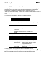
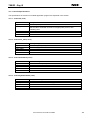
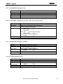
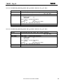
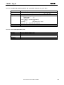
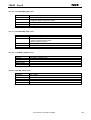
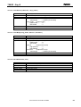
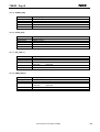
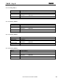
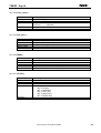
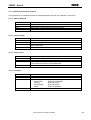
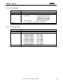
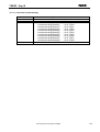
78K0R - Say it! 11.8 Variable/Constant Specifications The specifications of variables/constants in bundled application program are explained in this section. 11.8.1 Adpcm_Work[16] Variable/Constant Declaration Source File Use Remarks Adpcm_Work[16] static U16 Adpcm_Work[16] 78K0R_Voice.c Work area for compression/decompression library This should be located in resident area 11.8.2 output_data[2] Variable/Constant Declaration Source File Use Remarks output_data[2] static U16 output_data[2] 78K0R_Voice.c Output data buffer Store output data It outputs "output_data[0]" with the cycle interrupts 11.8.3 output_count Variable/Constant Declaration Source File Use Remarks output_count static U8 output_count 78K0R_Voice.c 62.5µs output counter This indicates the status of output data buffer - 11.8.4 ucPlaySts Variable/Constant Declaration Source File Use ucPlaySts static U8 ucPlaySts 78K0R_Voice.c Application play status Before Play Playing Stop Playing Break Remarks : STATUS_STANDBY : STATUS_PLAY : STATUS_STOP : STATUS_BREAK - User’s Manual U19237EE1V0UM00 87 78K0R - Say it! 11.8.5 stop_Led Variable/Constant Declaration Source File Use Remarks stop_Led static U8 stop_Led 78K0R_Voice.c LED blinking action when play is stopped - 11.8.6 PlayMode Variable/Constant Declaration Source File Use Remarks PlayMode static U8 PlayMode 78K0R_Voice.c To determine output mode (PWM, D/A) with interrupt process - 11.8.7 uiIntCounter1 Variable/Constant Declaration Source File Use Remarks uiIntCounter1 U32 uiIntCounter1 78K0R_Voice.c General purpose 1msec timer - 11.8.8 uiIntCounter2 Variable/Constant Declaration Source File Use Remarks uiIntCounter2 U32 uiIntCounter2 78K0R_Voice.c General purpose 1msec timer - User’s Manual U19237EE1V0UM00 88 78K0R - Say it! 11.8.9 usKeyStsCount[5] Variable/Constant Declaration Source File Use usKeyStsCount[5] U16 usKeyStsCount[5] 78K0R_Voice.c Joystick status counter Increment when ON with 1msec cycle handler usKeyStsCount[0] usKeyStsCount[1] msec usKeyStsCount[2] msec usKeyStsCount[3] msec usKeyStsCount[4] msec Remarks : UP Key continuous ON time in msec : PUSH Key continuous ON time in : LEFT Key continuous ON time in : RIGHT Key continuous ON time in : DOWN Key continuous ON time in - 11.8.10 ucKeyStsLocked[5] Variable/Constant Declaration Source File Use Remarks ucKeyStsLocked [5] U8 ucKeyStsLocked [5] 78K0R_Voice.c Joystick lock flag Set when continuous ON time exceeds certain value with 1msec cycle handler ucKeyStsLocked [0] : KEY_SHORT_ON (UP Key ON locked) : KEY_SHORT_OFF (UP Key OFF) ucKeyStsLocked [1] : KEY_SHORT_ON (PUSH Key ON locked) : KEY_LONG_ON (PUSH Key Long-ON locked) : KEY_SHORT_OFF (PUSH Key OFF) ucKeyStsLocked [2] : KEY_SHORT_ON (LEFT Key ON locked) : KEY_SHORT_OFF (LEFT Key OFF) ucKeyStsLocked [3] : KEY_SHORT_ON (RIGHT Key ON locked) : KEY_SHORT_OFF (RIGHT Key OFF) ucKeyStsLocked [4] : KEY_SHORT_ON (DOWN Key ON locked) : KEY_SHORT_OFF (DOWN Key OFF) - User’s Manual U19237EE1V0UM00 89 78K0R - Say it! 11.8.11 voice_adpcm[4] Variable/Constant Declaration Source File Use voice_adpcm[4] static struct tstsSOUND voice_adpcm[4] 78K0R_Voice.c Sound data information array U8 datatype (compression bit information) : 2 (ADPCM SP 16K 8x2bit) : 3 (ADPCM SP 24K 8x3bit) : 4 (ADPCM SP 32K 8x4bit) U32 datacount : Data count information U8 __far *address: Data address information Remarks - 11.8.12 ucAmpLevelTable[9] Variable/Constant Declaration Source File Use ucAmpLevelTable[9] static const U8 ucAmpLevelTable[9] 78K0R_Voice.c Amplifier volume level table (D/A output value) ucAmpLevelTable[0] ucAmpLevelTable[1] ucAmpLevelTable[2] ucAmpLevelTable[3] ucAmpLevelTable[4] ucAmpLevelTable[5] ucAmpLevelTable[6] ucAmpLevelTable[7] ucAmpLevelTable[8] Remarks : VLVL_AMP0 : VLVL_AMP1 : VLVL_AMP2 : VLVL_AMP3 : VLVL_AMP4 : VLVL_AMP5 : VLVL_AMP6 : VLVL_AMP7 : VLVL_AMP8 - User’s Manual U19237EE1V0UM00 90 78K0R - Say it! 11.8.13 ucVolumeLevelLEDTable[9] Variable/Constant Declaration Source File Use ucVolumeLevelLEDTable[9] static const U8 ucVolumeLevelLEDTable[9] 78K0R_Voice.c Volume level LED output table (I/O output value) ucVolumeLevelLEDTable[0] ucVolumeLevelLEDTable[1] ucVolumeLevelLEDTable[2] ucVolumeLevelLEDTable[3] ucVolumeLevelLEDTable[4] ucVolumeLevelLEDTable[5] ucVolumeLevelLEDTable[6] ucVolumeLevelLEDTable[7] ucVolumeLevelLEDTable[8] Remarks : VLVL_LED0 : VLVL_LED1 : VLVL_LED2 : VLVL_LED3 : VLVL_LED4 : VLVL_LED5 : VLVL_LED6 : VLVL_LED7 : VLVL_LED8 - User’s Manual U19237EE1V0UM00 91 78K0R - Say it! 12. Cables 12.1 USB interface cable (Mini-B type) Figure 35: USB interface cable (Mini-B type) User’s Manual U19237EE1V0UM00 92 VDD X2 FP1 Y1 P40 CSTCE20M0V53 3 XT1 XT2 T_RESET T_RESET 1 3 5 7 9 11 13 15 GND RES SI VDD SO 6 7 8 9 10 11 12 13 FL0 RESET_IN CLK_IN RESET 2 4 6 8 10 12 14 16 FLMD0 P41 (Shield) HIF3FC-16PA-2.54DSA Unmount R1 100 AVDD 3 2 1 Y2 MC-306 32.7680K-A0 T100 T99 T98 T97 T96 T95 T94 T93 T92 T91 T90 T89 T88 T87 T86 T85 T84 T83 T82 T81 T80 T79 T78 T77 T76 Q1 TPS851 SW1 (UP) 5 4 AGND 1 1 1 1 1 1 1 1 1 1 1 1 1 1 1 1 1 1 1 1 1 1 1 1 1 C2 10pF 100 99 98 97 96 95 94 93 92 91 90 89 88 87 86 85 84 83 82 81 80 79 78 77 76 ANI15 3 T5 1 1 1 T7 T8 T9 P41 P40 RESET XT2 XT1 FLMD0 X2 X1 (Shield) FLMD0 VDD C3 0.47uF T24 T25 1 1 P142/SCK20/SCL20 P141/PCLBUZ1/INTP7 P140/PCLBUZ0/INTP6 P120/INTP0/EXLVI P47/INTP2 P46/INTP1/TI05/TO05 P45/SO01 P44/SI01 P43/SCK01 P42/TI04/TO04 P41/TOOL1 P40/TOOL0 RESET P124/XT2 P123/XT1 FLMD0 P122/X2/EXCLK P121/X1 REGC VSS EVSS0 VDD EVDD0 P60/SCL0 P61/SDA0 78K0R/KG3_GC μPD78F1166GC-UEU-AX FLASH=256KB、RAM=12KB P157/ANI15 AVSS AVREF0 P111/ANO1 P110/ANO0 AVREF1 P10/EX24/SCK00 P11/EX25/SI00/RXD0 P12/EX26/SO00/TXD0 P13/EX27/TXD3 P14/EX28/RXD3 P15/EX29/RTCDIV/RTCCL P16/EX30/TI01/TO01/INTP5 P17/EX31/TI02/TO02 P57/EX15 P56/EX14 P55/EX13 P54/EX12 P53/EX11 P52/EX10 P51/EX9 P50/EX8 EVDD1 P30/INTP3/RTC1HZ P87/EX7 T26 T27 T28 T29 T30 T31 T32 P74 P73 P72 P71 P70 1 1 1 1 1 1 1 uPD78F1166GC-UEU-AX 1 4 P71 2 5 (LEFT) P72 3 6 R2 7.5K (RIGHT) P74 (DOWN) (COMMON) AGND VDD MR1 AVDD P80 75 74 73 72 71 70 69 68 67 66 65 64 63 62 61 60 59 58 57 56 55 54 53 52 51 SML512BC4T ANI15 LED1 P81 SML512BC4T P82 SML512BC4T P83 SML512BC4T P84 SML512BC4T P85 SML512BC4T P86 SML512BC4T LED2 ANO1 ANO0 1 1 1 1 T69 T68 T67 2 2 LED3 LED4 AGND 3 3 1 TO01 T62 If=1mA LED7 2 P87 SML512BC4T LED8 VDD VDD P50 1 P87 8 7 6 5 4 3 2 1 CN1J8-302 LED6 T64 P57 P56 P55 P54 P53 P52 P51 P50 9 10 11 12 13 14 15 16 LED5 P13 P14 SML512BC4T LED9 T52 P51 SML512BC4T P52 SML512BC4T P53 SML512BC4T P54 SML512BC4T P55 SML512BC4T P56 SML512BC4T P57 SML512BC4T LED10 LED11 LED12 LED13 LED14 MR2 16 15 14 13 12 11 10 9 1 2 3 4 5 6 7 8 CN1J8-302 If=1mA LED15 LED16 AVDD 3 3 3 P73 SKRHABE010 1 1 P41 P40 RESET 1 P70 (PUSH) P80 P81 P82 P83 P84 P85 P86 T10 3 3 3 1 T1 T2 T3 T41 T42 SW3 1 2 SKQMBB 2 SKQMBB 1 2 3 4 5 6 7 8 9 10 11 12 13 14 15 16 17 18 19 20 21 22 23 24 25 P62 P63 P31/TI03/TO03/INTP4 P64/RD P65/WR0 P66/WR1 P67/ASTB P77/EX23/KR7/INTP11 P76/EX22/KR6/INTP10 P75/EX21/KR5/INTP9 P74/EX20/KR4/INTP8 P73/EX19/KR3 P72/EX18/KR2 P71/EX17/KR1 P70/EX16/KR0 P06/WAIT P05/CLKOUT EVSS1 P80/EX0 P81/EX1 P82/EX2 P83/EX4 P84/EX4 P85/EX5 P86/EX6 SW2 1 1 1 1 P143/SI20/RXD2/SDA20 P144/SO20/TXD2 P145/TI07/TO07 P00/TI00 P01/TO00 P02/SO10/TXD1 P03/SI10/RXD1/SDA10 P04/SCK10/SCL10 P131/TI06/TO06 P130 P20/ANI0 P21/ANI1 P22/ANI2 P23/ANI3 P24/ANI4 P25/ANI5 P26/ANI6 P27/ANI7 P150/ANI8 P151/ANI9 P152/ANI10 P153/ANI11 P154/ANI12 P155/ANI13 P156/ANI14 U1 26 27 28 29 30 31 32 33 34 35 36 37 38 39 40 41 42 43 44 45 46 47 48 49 50 C1 10pF P77 P76 P75 + C4 4.7uF/25V AGND VDD C5 C6 0.1uF 0.1uF + AGND C7 4.7uF/25V C8 C9 0.1uF 0.1uF AGND VDD Unmount DCVDD CN1 HEC0470-01-630 1 2 3 VDD DCVDD USBVDD VDD JP1 1 2 JP2 R3 330 1 2 AVDD R4 3 FFC-2AMEP1_XXX LED17 PG1112H XXX NF1 NFM41PC204F1H3 1 3 2 FFC-3AMEP1 VDD R5 0ohm 78K0R/KG3 AGND Title TK-78K0R/KG3+Voice Size A3 Date: Document Number 62-0167A Thursday , January 18, 2007 Rev 1.0 Sheet 1 of 3 78K0R - Say it! 13. Schematics User’s Manual U19237EE1V0UM00 Figure 36: 78K0R - Say it! schematics 1/3 X1 93 C10 R8 + R7 2 33K R6 1 1 2 1 1 ANO0 2 33K AVDD 22K 10uF/16V 2 4 R9 33K 2 - 3 + AVDD AGND AVDD Y 1 AVDD U2A 1 2 33K 2 + C12 4.7uF/25V AGND R12 20K 22K 10uF/16V AVDD R13 22K AGND 2 SN74LVC1G14DCK R11 1 AGND C13 0.1uF 2 GND 1 C11 R10 4 1 VCC A 3 + 2 TO01 5 1 NC PWM IN 1 LMV324M 11 U3 1 78K0R - Say it! AGND C14 R14 20K AGND 2 0.1uF AGND AGND C15 C16 C17 1800pF AGND AGND AGND AGND 4 5 SW4 1 11 シ ルク: R21 10K R23 39K 2 C24 AGND AGND AGND R27 10K R28 10K 2 2 R30 R31 R32 AGND 2 6 AGND AGND R29 10K 1 7 U2B 1 1000pF 1200pF 1 1 AGND 5 LMV324M 1 6800pF 1000pF R22 12K R25 36K 6 3 4 2 1000pF 2 39K C19 2 R26 24K C25 2 C27 C18 U2C 1000pF SSSS222700 1 2 8 2 C26 LMV324M 11 11 1000pF R24 30K 1 2 10 U2D 1 12 9 C21 14 1 1000pF C20 2 39K 1 1000pF 13 + C23 2 36k 36K LMV324M - C22 1 1 4 24K 1 R20 2 4 1 2 24K R19 2 + 1 - 2 R16 R15 + R17 1 AVDD 2200pF AVDD 2200pF AVDD 2200pF R18 - User’s Manual U19237EE1V0UM00 Figure 37: 78K0R - Say it! schematics 2/3 D/A IN 1 1 AGND AGND 1 2 2 20K 12K 18K 4 ANO1 Vo2 8 1 CN2 LGY6501-0900F R33 150 2 By pass 2 4 1 100uF/16V 2 1 2 100K 3 HP Sense 6 AGND GND R35 1.0uF XXX AGND AGND LM4865M AVDD 0.1uF R36 1 2 100K AGND 1 2 DC Vol/SD 3 4 1 C30 Unmount AVDD C32 5 NDT-03C 7 R34 + C31 4.7uF/25V C29 Vo1 LS1 0.22uF 1 -Vin + 2 VDD U4 C28 1 AVDD AGND Audio AGND Title TK-78K0R/KG3+Voice Size A3 Date: Document Number 62-0167A Thursday , January 18, 2007 Rev 1.0 Sheet 2 of 3 94 78K0R - Say it! P00 3 INTP0 4 RESETU 5 CN1J8-103 7 1 MR3-7 FLMD0U 6 CSTCE16M0V53-R0 Y3 USBVDD 7 8 C33 1 C34 4.7uF/25V 0.47uF 10 11 P14/RxD6 FLMD0 P15 P122/X2/EXCLK/OCD0B EVss Vdd EVdd 26 RxD6 24 P16 23 TI50 22 P33/TI51/TO51 Vss TPU3 TxD6 FLMD0U P17/TI50/TO50 REGC 1 27 25 P16/TOH1 P121/X1/OCD0A 28 (Shield) MR3-8 CN1J8-103 21 USBVDD 13 33 33 14 15 USBREGC P31/INTP2/OCD1A USBP P32/INTP3/OCD1B USBM P60 USBPUC 19 (Shield) 18 (Shield) 17 TPU8 TPU9 16 P61 USBVDD uPD78F0730 5 R39 10K 1.5K 1 R40 4 1 1 2 FG4 FG3 FG2 FG1 2 5 2 3 2 U6 2 1 FG4 FG3 FG2 FG1 GND TPU6 TPU7 20 1 12 4 ID_NC RESET TPU2 USBVDD 1 2 2 P13/TxD6 TPU1 1 1 1 1 P12/SO10 P120/INTP0/EXLVI 1 29 C36 0.1uF 2 R37 R38 P00/TI000 30 1 2 0.47uF 2 3 P11/SI10 1 1 1 DD+ USBVDD C35 USB1 UX60A-MB-5ST VBUS 9 P10/SCK10 P01/TI010/TO00 9 + L1 BLM41PG750S 1 2 2 P30/INTP1 1 10 2 1 1 P01 8 INTP1 TPU5 1 TPU4 C37 0.1uF C38 0.1uF SN74LVC1G125DCK C39 0.1uF VDD VDD 4 RxD6 2 USBVDD DIR A B 5 7 INTP0 RxD6Buf TxD6Buf 1 1 1 1 C41 0.1uF 1 2 VDD 6 TxD6Buf 2 SN74LVC2G07DCK 2 C42 0.1uF R43 10K 1 2 3 4 5 6 7 8 P75 P76 P77 C40 0.1uF 1 11 1 1 SW5 RxD6Buf R42 3.0K U8A 6 TxD6 VDD VDD SN74LVC2T45DCU VDD CN1J8-103 MR3-6 5 VDD USBVDD R41 3.0K 2 GND 8 1 VCCA VCCB 2 1 1 U7A 2 USBVDD 16 15 14 13 12 11 10 9 2 2 User’s Manual U19237EE1V0UM00 Figure 38: 78K0R - Say it! schematics 3/3 U5 USBVDD P40 (Tool0) 1 VDD USBVDD U7B P13 (TxD3) 1 P14 (RxD3) 1 8 5 CHS-08B 1 6 (Shield) P41 VCCB VCCA DIR GND B A 1 4 3 (Shield) TI50 SN74LVC2T45DCU P00 VDD 1 8 2 4 1 6 FLMD0 1 C43 0.1uF 2 16 R44 1.5K 2 U9A MR3-1 CN1J8-103 1 VDD 1 VDD SN74LVC2G126DCU 5 R45 2 1 100 3 2 U8B 4 INTP1 MR3-2 CN1J8-103 MR3-4 CN1J8-103 8 5 4 3 RESET RESET 1 USB Title TK-78K0R/KG3+Voice SN74LVC2G126DCU SN74LVC2G07DCK 15 SKQMBB 2 U9B P01 4 SW6 1 VDD CN1J8-103 MR3-3 VDD 13 CN1J8-103 RESET 3 12 14 MR3-5 5 P16 USBVDD 7 1 2 T_RESET Size A3 Date: Document Number 62-0167A Wednesday , January 17, 2007 Rev 1.0 Sheet 3 of 3 95 78K0R - Say it! [MEMO] User’s Manual U19237EE1V0UM00 96