1
Freescale Semiconductor, Inc.
Application Note
AN2355/D
11/2002
Freescale Semiconductor, Inc...
Sensorless BLDC
Motor Control
on MC68HC908MR32
Software Description
By Libor Prokop and Leos Chalupa
Roznov System Application Laboratory
Roznov, Czech Republic
General Description
This application note describes 3-phase sensorless brushless dc (BLDC) motor
control with back-EMF (electromotive force) zero-crossing sensing. The
application serves as an example of a sensorless BLDC motor control system
using Motorola’s MC68HC908MR32 microcontroller unit (MCU). This system
can be easily ported to other derivatives of the M68HC908MRx Family. The
application note also illustrates the use of dedicated motor control on chip
peripherals.
The application note gives a view on brushless dc motor control. It describes
the application system concept with sensorless control techniques. The main
part of this document gives a detailed description of the software for the BLDC
sensorless back-EMF zero crossing application.
For application software use and parameter configuration to a customer motor,
refer to the complementary application note entitled Sensorless BLDC Motor
Control on MC68HC908MR32 — Software Porting to Customer Motor
(Motorola document order number AN2356/D). That application note will also
help to decide if the software and control method shown is suitable for a specific
customer application.
BLDC Motor Control
BLDC Motor
Targeted by This
Application
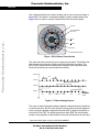
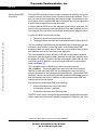
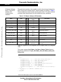
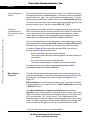
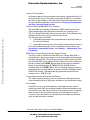
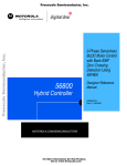
The brushless dc motor (BLDC motor) is also referred to as an electronically
commutated motor. There are no brushes on the rotor, and commutation is
performed electronically at certain rotor positions. The stator magnetic circuit is
usually made from magnetic steel sheets. Stator phase windings are inserted
in the slots (distributed winding) as shown in Figure 1, or it can be wound as
one coil on the magnetic pole. Magnetization of the permanent magnets and
their displacement on the rotor are chosen in such a way that the back-EMF
© Motorola, Inc., 2002
For More Information On This Product,
Go to: www.freescale.com
Freescale Semiconductor, Inc.
AN2355/D
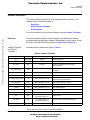
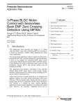
(the voltage induced into the stator winding due to rotor movement) shape is
trapezoidal. This allows a rectangular shaped 3-phase voltage system (see
Figure 2) to be used to create a rotational field with low torque ripples.
STATOR
STATOR WINDING
(IN SLOTS)
Freescale Semiconductor, Inc...
SHAFT
ROTOR
AIR GAP
PERMANENT MAGNETS
Figure 1. BLDC Motor Cross Section
The motor can have more than just one pole-pair per phase. This defines the
ratio between the electrical revolution and the mechanical revolution. The
BLDC motor shown has three pole-pairs per phase, which represent three
electrical revolutions per one mechanical revolution.
Voltage
VOLTAGE
120°
120°
Phase
PHASEAA
Phase
PHASEBB
Phase
PHASECC
30°
30°
90°
90°
150°
150°
210°
210°
270°
270°
330°
330°
ELECTRICAL
electrical
ANGLE
angle
Figure 2. 3-Phase Voltage System
The easy to create rectangular shape of applied voltage ensures the simplicity
of control and drive. But, the rotor position must be known at certain angles in
order to align the applied voltage with the back-EMF (voltage induced due to
movement of the PM). The alignment between back-EMF and commutation
events is very important. In this condition, the motor behaves as a dc motor and
Sensorless BLDC Motor Control on MC68HC908MR32
2
Software Description
For More Information On This Product,
Go to: www.freescale.com
MOTOROLA
Freescale Semiconductor, Inc.
AN2355/D
BLDC Motor Control
runs at the best working point. Thus, simplicity of control and good performance
make this motor a natural choice for low-cost and high-efficiency applications.
Freescale Semiconductor, Inc...
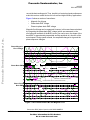
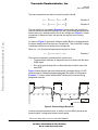
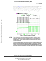
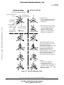
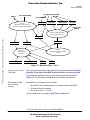
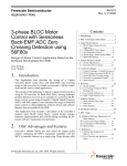
Figure 3 shows a number of waveforms:
•
Magnetic flux linkage
•
Phase back-EMF voltage
•
Phase-to-phase back-EMF voltage
Magnetic flux linkage can be measured. However, in this case it was calculated
by integrating the phase back-EMF voltage (which was measured on the
non-fed motor terminals of the BLDC motor). As can be seen, the shape of the
back-EMF is approximately trapezoidal and the amplitude is a function of the
actual speed. During speed reversal, the amplitude changes its sign and the
phase sequence changes.
Phase Magnetic
Flux Linkage
Psi_A
Psi_B
Psi_C
PH. A
PH. B
Phase Back EMF
PH. C
Ui_A
PH. A
Ui_B
PH. B
Atop
Btop
Ctop
Cbot Abot
PH. C
SPEED
REVERSAL
Speed
reversal
Ui_C
“NATURAL” COMMUTATION
POINT point
“Natural”
commutation
Bbot
ACTING POWER SWITCH IN THE POWER STAGE
Phase-Phase
Back EMF
Ui_AB
Ui_BC
Ui_CA
A–B
B–C
C–A
Figure 3. BLDC Motor Back EMF and Magnetic Flux
Sensorless BLDC Motor Control on MC68HC908MR32
MOTOROLA
Software Description
For More Information On This Product,
Go to: www.freescale.com
3
Freescale Semiconductor, Inc.
AN2355/D
Freescale Semiconductor, Inc...
The filled areas in the tops of the phase back-EMF voltage waveforms indicate
the intervals where the particular phase power stage commutations occur. The
power switches are cyclically commutated through the six steps; therefore, this
technique is sometimes called six step commutation control. The crossing
points of the phase back-EMF voltages represent the natural commutation
points. In normal operation the commutation is performed here. Some control
techniques advance the commutation by a defined angle in order to control the
drive above the pulse-width modulator (PWM) voltage control.
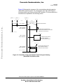
3-Phase BLDC
Power Stage
The voltage for 3-phase BLDC motor is provided by a 3-phase power stage
controlled by digital signals. Its topology is the one as for the AC induction
motor (refer to Figure 5). The power stage is usually controlled by a dedicated
microcontroller with on-chip PWM module.
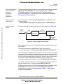
Why Sensorless
Control?
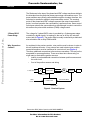
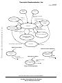
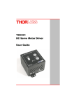
As explained in the previous section, rotor position must be known in order to
drive a brushless dc motor. If any sensors are used to detect rotor position,
sensed information must be transferred to a control unit (see Figure 4).
Therefore, additional connections to the motor are necessary. This may not be
acceptable for some applications. There are at least two reasons why you
might want to eliminate the position sensors:
•
Inability to make additional connections between position sensors and
the control unit
•
Cost of the position sensors and wiring
–
AC LINE VOLTAGE
=
M
POWER STAGE
POSITION
SENSORS
LOAD
CONTROL SIGNALS
SPEED
SETTING
POSITION FEEDBACK
CONTROL UNIT
MOTOR DRIVE
Figure 4. Classical System
Sensorless BLDC Motor Control on MC68HC908MR32
4
Software Description
For More Information On This Product,
Go to: www.freescale.com
MOTOROLA
Freescale Semiconductor, Inc.
AN2355/D
BLDC Motor Control
Power Stage —
Motor System Model
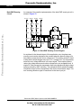
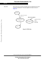
In order to explain and simulate the idea of back-EMF sensing techniques a
simplified mathematical model based on the basic circuit topology has been
created. See Figure 5.
Id0
+
ud/2
=
SAt
S Bt
SCt
+
Freescale Semiconductor, Inc...
ud/2
=
SAb
ISa
ISb
S Bb
ISc
SCb
-
u VA
u AB
u BC
u VB
uVC
uCA
B
uRb
u Sb
u0
uLb
ubackEMF b
O ubackEMF c
uSa
u
uLa backEMF a
A
uRa
uLc
uSc
uRc
C
Figure 5. Power Stage — Motor Topology
The second goal of the model is to find how the motor characteristics depend
on the switching angle. The switching angle is the angular difference between
a real switching event and an ideal one (at the point where the phase-to-phase
back-EMF crosses zero).
The motor-drive model consists of a normal 3-phase power stage plus a
brushless dc motor. Power for the system is provided by a voltage source (Ud).
Six semiconductor switches (SA/B/C t/b), controlled elsewhere, allow the
rectangular voltage waveforms (see Figure 2) to be applied. The
semiconductor switches and diodes are simulated as ideal devices. The natural
voltage level of the whole model is put at one half of the dc-bus voltage. This
simplifies the mathematical expressions.
Sensorless BLDC Motor Control on MC68HC908MR32
MOTOROLA
Software Description
For More Information On This Product,
Go to: www.freescale.com
5
Freescale Semiconductor, Inc.
AN2355/D
Stator Winding
Equations
The BLDC motor is usually very symmetrical. All phase resistances, phase and
mutual inductances, flux-linkages can be thought of as equal to, or as a function
of the position θ with a 120° displacement.
The electrical BLDC motor model then consists of a set of the following stator
voltage equations Equation 1.
i Sa
Ψ Sa
d
= R S i Sb +
Ψ
d t Sb
i Sc
Ψ Sc
u Sa
u Sb
Freescale Semiconductor, Inc...
u Sc
Equation 1
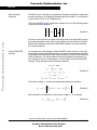
The task of this section is to explain the background of the back-EMF sensing
and to demonstrate how the zero crossing events can be detected. Parasitic
effects that negatively influence the back-EMF detection are discussed and
their nature analyzed.
Indirect Back EMF
Sensing
Let us assume a usual situation, where the BLDC motor is driven in six-step
commutation mode using PWM technique, where both top and bottom switches
in the diagonal are controlled using the same signal (so called “hard switching
PWM” technique). The motor phases A and B are powered, and phase C is
free, having no current. So the phase C can be used to sense the back-EMF
voltage. This is described by the following conditions:
S Ab, S Bt ← PWM
−1
--- u d, u VB = ± 1
--- u d
u VA = +
2
2
i Sa = – i Sb = i, di Sa = – di Sb = di
Equation 2
i Sc = 0, di Sc = 0
u backEMF a + u backEMF b + u backEMF c = 0
The branch voltage uVc can be calculated using the above conditions,
c
u VC
1
= u Sc – --3
∑u
backEMF x
di
+ ( L ac – L bc ) ---- – u VC
dt
Equation 3
x=a
After evaluation the expression of the branch voltage uVc is as follows:
di
3
1
u VC = --- u backEMF c – --- ( L ac – L bc ) ---dt
2
2
Equation 4
Sensorless BLDC Motor Control on MC68HC908MR32
6
Software Description
For More Information On This Product,
Go to: www.freescale.com
MOTOROLA
Freescale Semiconductor, Inc.
AN2355/D
BLDC Motor Control
The same expressions can also be found for phase A and B:
di
3
1
u VA = --- u backEMF a – --- ( L ba – L ca ) ---dt
2
2
Equation 5
di
3
1
u VB = --- u backEMF b – --- ( L cb – L ab ) ---dt
2
2
Equation 6
Freescale Semiconductor, Inc...
The first member in the equation Equation 6 demonstrates the possibility to
indirectly sense the back-EMF between the free (not powered) phase terminal
and the zero point, defined at half of the dc-bus voltage (see Figure 5). Simple
comparison of these two levels can provide the required zero crossing
detection.
As shown in Figure 5, the branch voltage of phase B can be sensed between
the power stage output B and the zero voltage level. Thus, back-EMF voltage
is obtained and the zero crossing can be recognized.
When Lcb = Lab, this general expressions can also be found:
3
u Vx = --- u backEMFx where x = A ,B ,C
2
Equation 7
There are two necessary conditions which must be met:
•
Top and bottom switches (in diagonal) have to be driven with the same
PWM signal
•
No current goes through the non-fed phase that is used to sense the
back-EMF
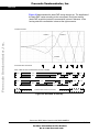
Figure 6 shows branch and motor phase winding voltages during a 0–360°
electrical interval. Shaded rectangles designate the validity of the equation
Equation 7. In other words, the back-EMF voltage can be sensed during
designated intervals.
0
30
60
90
120
150
180
210
240
270
300
330
360
390
uVA
uSa
- Back-EMF can be sensed
Figure 6. Phase Voltage Waveform
However simple this solution looks, in reality it is more difficult, because the
sensed “branch” voltage also contains some ripples.
Sensorless BLDC Motor Control on MC68HC908MR32
MOTOROLA
Software Description
For More Information On This Product,
Go to: www.freescale.com
7
Freescale Semiconductor, Inc.
AN2355/D
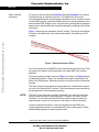
Effect of Mutual
Inductance
As shown in previous equations Equation 4 through Equation 6, the mutual
inductances play an important role here. The difference of the mutual
inductances between the coils which carry the phase current, and the coil used
for back-EMF sensing, causes the PWM pulses to be superimposed onto the
detected back-EMF voltage. In fact, it is produced by the high rate of change of
phase current, transferred to the free phase through the coupling of the mutual
inductance.
Freescale Semiconductor, Inc...
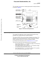
Figure 7 shows the real measured “branch” voltage. The red curves highlight
the effect of the difference in the mutual inductances. This difference is not
constant.
0V
Figure 7. Mutual Inductance Effect
Due to the construction of the BLDC motor, both mutual inductances vary. They
are equal at the position that corresponds to the back-EMF zero crossing
detection.
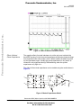
The branch waveform detail is shown in Figure 8. Channel 1 in Figure 8 shows
the disturbed “branch” voltage. The superimposed ripples clearly match the
width of the PWM pulses, and thus prove the conclusions from the theoretical
analysis.
The effect of the mutual inductance corresponds well in observations carried
out on the five different BLDC motors. These observations were made during
the development of the sensorless technique.
NOTE:
The BLDC motor with stator windings distributed in the slots has technically
higher mutual inductances than other types. Therefore, this effect is more
significant. On the other hand the BLDC motor with windings wounded on
separate poles, shows minor presence of the effect of mutual inductance.
However noticeable this effect, it does not degrade the back-EMF zero
crossing detection because it is cancelled at the zero crossing point. Simple
additional filtering helps to reduce ripples further.
Sensorless BLDC Motor Control on MC68HC908MR32
8
Software Description
For More Information On This Product,
Go to: www.freescale.com
MOTOROLA
Freescale Semiconductor, Inc.
Freescale Semiconductor, Inc...
AN2355/D
BLDC Motor Control
Figure 8. Detail of Mutual Inductance Effect
Effect of Mutual
Phase Capacitance
The negative effect of mutual inductance is not the only one to disturb the
back-EMF sensing. So far, the mutual capacitance of the motor phase windings
was neglected in the motor model, since it affects neither the phase currents
nor the generated torque. Usually the mutual capacitance is very small. Its
influence is only significant during PWM switching, when the system
experiences very high du/dt.
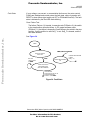
The effect of the mutual capacitance can be studied using the model shown in
Figure 9.
Id0
A
+
ud/2
=
C
S At
SBt
C
iCab
u VA
iC
u Cba
+
=
RC
RC
-
ud/2
u Cac
iC
S Ab
SBb
C
ISb
RC
-
uVB
uVC Cap
C
u Ccb
B
Figure 9. Mutual Capacitance Model
Sensorless BLDC Motor Control on MC68HC908MR32
MOTOROLA
Software Description
For More Information On This Product,
Go to: www.freescale.com
9
Freescale Semiconductor, Inc.
AN2355/D
Let us focus on the situation when the motor phase A is switched from negative
dc-bus rail to positive, and the phase B is switched from positive to negative.
This is described by these conditions Equation 8:
S Ab, S Bt ← PWM
1
1
1
1
u VA = – --- u d → --- u d, u VB = --- u d → – --- u d
2
2
2
2
i Cac = i Ccb = i C
Equation 8
The voltage that disturbs the back-EMF sensing, utilizing the free (not
powered) motor phase C, can be calculated based the equation:
Freescale Semiconductor, Inc...
u VC
Cap
1
1
= --- ( u Ccb + u Cac + 2R C ) – ( u Ccb + R C ) = --- ( u Cac – u Ccb )
2
2
Equation 9
The final expression for disturbing voltage can be found as follows:
u VC
Cap
1 1
1 C cb – C ac
1
= --- -------- – -------- i C dt = --- ---------------------i dt
2 C ac C cb
2 C cb ⋅ C ac C
∫
∫
Equation 10
Equation 10 expresses the fact that only the unbalance of the mutual
capacitance (not the capacitance itself) disturbs the back-EMF sensing. When
both capacities are equal (they are balanced), the disturbances disappear. This
is demonstrated in Figure 10 and Figure 11.
Figure 10. Distributed Back-EMF by Unbalanced Capacity Coupling
Sensorless BLDC Motor Control on MC68HC908MR32
10
Software Description
For More Information On This Product,
Go to: www.freescale.com
MOTOROLA
Freescale Semiconductor, Inc.
AN2355/D
BLDC Motor Control
Freescale Semiconductor, Inc...
Channel 1 in Figure 11 shows the disturbed “branch” voltage, while the other
phase (channel 2) is not affected because it faces balanced mutual
capacitance. The unbalance was purposely made by adding a small capacitor
on the motor terminals, in order to better demonstrate the effect. After the
unbalance was removed the “branch” voltage is clean, without any spikes.
Figure 11. Balanced Capacity Coupling
NOTE:
The configuration of the phase windings end-turns has significant impact;
therefore, it needs to be properly managed to preserve the balance in the
mutual capacity. This is important, especially for prototype motors that are
usually hand-wound.
Failing to maintain balance in the mutual capacitance can easily disqualify such
a motor from using sensorless techniques based on the back-EMF sensing.
Usually, the BLDC motors with windings wound on separate poles show minor
presence of the mutual capacitance. Thus, the disturbance is also insignificant.
Sensorless BLDC Motor Control on MC68HC908MR32
MOTOROLA
Software Description
For More Information On This Product,
Go to: www.freescale.com
11
Freescale Semiconductor, Inc.
AN2355/D
An example of the possible implementation of the back-EMF sensing circuit is
shown in Figure 12.
560k
560k
560k
560k
560k
560k
560k
560k
560k
1n
2x27k
1n
2x27k
1n
2x27k
1n
MUX
–
+
Freescale Semiconductor, Inc...
PHASE C
–
+
+DC_BUS PHASE A PHASE B
–
+
Back-EMF Sensing
Circuit
MUX COMMAND
ZERO
CROSSING
DETECTION
SIGNAL
2x27k
Figure 12. Back-EMF Sensing Circuit Diagram
As explained in the theoretical part of this application note, the phase zero
crossing event can be detected at the moment when the branch voltage (of a
free phase) crosses the half dc-bus voltage level. The resistor network is used
to step down sensed voltages down to a 0–15 V voltage level. The comparators
sense the zero voltage difference in the input signal. The multiple resistors
reduce the voltage across each resistor component to an acceptable level. A
simple RC filter prevents the comparators from being disturbed by high voltage
spikes produced by IGBT switching. The multiplexer (MUX) selects the phase
comparator output, which corresponds to the current commutation stage. This
zero crossing detection signal is transferred to the timer input pin.
Sensorless BLDC Motor Control on MC68HC908MR32
12
Software Description
For More Information On This Product,
Go to: www.freescale.com
MOTOROLA
Freescale Semiconductor, Inc.
AN2355/D
Application Specification
The comparator control and zero crossing signals plus the voltage waveforms
are shown in Figure 13.
Phase Selection
MUX Command
Freescale Semiconductor, Inc...
Phase Comparator
Output
(Zero crossing edge)
"Branch" Voltage
(Interval of phase
Back-EMF zero
crossing detection)
Reference Level
Commutation
Signal
90°
Zero Crossing
Signal
Figure 13. The Zero Crossing Detection
Application Specification
The concept of the application is that of a speed-closed loop drive using
back-EMF zero crossing technique for position detection.
The system for BLDC motor control consists of hardware and software. The
application uses universal Modular Motion Control Development Hardware
boards, povided by Motorola for customer development support.
For hardware board descriptions refer to References 3., 4., 5., 6., and 7..
There are three board and motor hardware sets for the application
•
High-voltage hardware set — for variable line voltage 115–230 Vac and
medium power (phase current < 2.93A)
•
Low-voltage evaluation motor hardware set — for automotive voltage
(12 V) and very low power (phase current < 4A)
•
Low-voltage hardware set — for automotive voltage (12 V or possibly
42 V) and medium power (phase current < 50A)
Sensorless BLDC Motor Control on MC68HC908MR32
MOTOROLA
Software Description
For More Information On This Product,
Go to: www.freescale.com
13
Freescale Semiconductor, Inc.
AN2355/D
The application software is practically the same for all three hardware
platforms, needing only to be modified to include one of three constant
customizing files containing hardware and motor parameter settings.
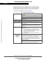
The application specifications are listed in Table 1.
Table 1. Application Specifications
Control Algorithm
3-phase trapezoidal BLDC motor control star or delta!
connected
Sensorless with back-EMF zero crossing commutation control
Freescale Semiconductor, Inc...
Speed closed loop control
Motoring mode
Target Processor
MC68HC908MR32
Software Language
C-language with some arithmetical functions in assembler
Application Control
Manual interface (start/stop switch, speed potentiometer control,
LED indication)
PC master software (remote) interface (via RS232 using PC
computer)
Targeted Hardware
Software
Configuration
and Parameter
Settings
Software is prepared to run on three optional board and motor
hardware sets:
1. High voltage hardware set at variable line voltage
115–230 Vac (software customizing file const_cust_hv.h)
2. Low voltage evaluation motor hardware set (software
customizing file const_cust_evmm.h)
3. Low voltage hardware set (software customizing file
const_cust_lv.h)
Configuration to one of the three required hardware is provided by
an include of the dedicated software customizing file (the software
pack contains the files const_cust_hv.h, const_cust_lv.h,
const_cust_evm.h, with predefined parameter settings for running
on one of the optional board and motor hardware sets. The
required hardware needs to be selected in code_fun.c file by one
of these files #include)
When software is configured for a different customer motor, the
software configuration for any motor is provided in the dedicated
customizing file according to the hardware board used
Sensorless BLDC Motor Control on MC68HC908MR32
14
Software Description
For More Information On This Product,
Go to: www.freescale.com
MOTOROLA
Freescale Semiconductor, Inc.
AN2355/D
System Concept
System Concept
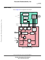
Refer to Figure 14 for the application block diagram.
Three-Phase
Inverter
DC Bus Current &
DC Bus Voltage
Sensing
Freescale Semiconductor, Inc...
Power line
3-ph
BLDC
Motor
3 BEMF Voltage
Zero Crossing
Comparators
3 phase BLDC
Power Stage
MUX
DC-Bus Voltage/
Current
Temperature
BEMF Zero
Crossing
signal
Digital
Inputs
ADC
Zero
Crossing
PC Master
SCI
MUX
Command
Digital
Outputs
PWM
Generator
with
Dead Time
Zero Crossing
Time moment
Zero Crossing
Period, Position
Recognition
PWM
Commutation
Control
Duty
Cycle
Commutation
Period
1/T
START
STOP
Actual Speed
Required
Speed
Speed PI
Regulator
SPEED
Required
Alignment
Current
Actual
Current
Current PI
Regulator
(for Alignment)
HC08MR32
Figure 14. System Concept
Sensorless BLDC Motor Control on MC68HC908MR32
MOTOROLA
Software Description
For More Information On This Product,
Go to: www.freescale.com
15
Freescale Semiconductor, Inc.
AN2355/D
Freescale Semiconductor, Inc...
The sensorless rotor position technique detects the zero crossing points of
back-EMF induced in the motor windings. The phase back-EMF zero crossing
points are sensed while one of the three phase windings is not powered. The
information obtained is processed in order to commutate the energized phase
pair and control the phase voltage, using pulse width modulation.
The back-EMF zero crossing detection enables position recognition. The
resistor network is used to step down the sensed voltages to a 0–3.3 V voltage
level. In order to filter high voltage spikes produced by the switching of the
IGBTs (MOSFETs), zero crossing detection is synchronized with the middle of
a central aligned PWM signal by the software. The software selects by MUX
command the phase comparator output that corresponds to the current
commutation step. The MUX circuit selects this signal, which is transferred to
the MCU Input.
The voltage drop resistor is used to measure the dc-bus current which is
chopped by the PWM. The signal obtained is rectified and amplified (0–3.3 V
with 1.65 V offset). The internal MCU analog-to-digital (A/D) converter and zero
crossing detection are synchronized with the PWM signal. This synchronization
avoids spikes when the IGBTs (or MOSFETs) are switched, and simplifies the
electric circuit.
During the rotor alignment state, the dc-bus current is controlled by the current
PI regulator. In the other states (motor running), the phase voltage (PWM duty
cycle) is controlled by the speed PI regulator.
The A/D converter is also used to sense the dc-bus voltage and drive
temperature. The dc-bus voltage is stepped down to a 3.3 V signal level by a
resistor network.
The six IGBTs (copack with built-in fly back diode), or MOSFETs, and gate
drivers create a compact power stage. The drivers provide the level shifting that
is required to drive high side switch. PWM technique is used to control motor
phase voltage.
Control Technique
Sensorless
Commutation
Control
This section concentrates on sensorless BLDC motor commutation with
back-EMF zero crossing technique.
In order to start and run the BLDC motor, the control algorithm has to go
through the following states:
•
Alignment
•
Starting (Back-EMF Acquisition)
•
Running
Sensorless BLDC Motor Control on MC68HC908MR32
16
Software Description
For More Information On This Product,
Go to: www.freescale.com
MOTOROLA
Freescale Semiconductor, Inc.
AN2355/D
Control Technique
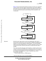
Figure 15 shows the transitions between the states. First the rotor is aligned to
a known position; then the rotation is started without the position feedback.
When the rotor moves, back-EMF is acquired so the position is known, and can
be used to calculate the speed and processing of the commutation in the
running state.
Freescale Semiconductor, Inc...
START MOTOR
ALIGNMENT
ALIGNMENT TIME
EXPIRED?
NO
YES
STARTING
(BACK-EMF ACQUISITION)
MINIMAL CORRECT
COMMUTATIONS DONE?
NO
YES
RUNNING
Figure 15. Commutation Control Stages
Alignment
Before the motor starts, there is a short time (depending on the motor’s
electrical time constant) when the rotor position is stabilized by applying PWM
signals to only two motor phases (no commutation). The current controller
keeps current within predefined limits. This state is necessary in order to create
a high start-up torque. When the preset time-out expires then this state is
finished.
The current controller subroutine, with PI regulator, is called to control dc-bus
current. It sets the correct PWM ratio for the required current. The current PI
controller works with constant execution (sampling) period. This period should
be a multiple of the PWM period, in order to synchronize the current
measurement with PWM:
Current controller period = n/PWM frequency
Sensorless BLDC Motor Control on MC68HC908MR32
MOTOROLA
Software Description
For More Information On This Product,
Go to: www.freescale.com
17
Freescale Semiconductor, Inc.
AN2355/D
Freescale Semiconductor, Inc...
The BLDC motor rotor position with flux vectors during alignment is shown in
Figure 16.
Figure 16. Alignment
Running
The commutation process is a series of states which assure:
• The back-EMF zero crossing is successfully captured
• The new commutation time is calculated
• The commutation is performed
The following processes need to be provided:
• BLDC motor commutation service
• Back-EMF zero crossing moment capture service
• Calculation of commutation time
• Interactions between these commutation processes
From diagrams an overview of how the commutation works can be understood.
After commuting the motor phases, there is a time interval (Per_Toff[n]) when
the shape of back-EMF must stabilized (after the commutation the fly-back
diodes are conducting the decaying phase current; therefore, sensing of the
back-EMF is not possible). Then the new commutation time (T2[n]) is preset.
The new commutation will be performed at this time if the back-EMF zero
crossing is not captured. If the back-EMF zero crossing is captured before the
preset commutation time expires, then the exact calculation of the commutation
time (T2*[n]) is made, based on the captured zero crossing time (T_ZCros[n]).
The new commutation is performed at this new time.
Sensorless BLDC Motor Control on MC68HC908MR32
18
Software Description
For More Information On This Product,
Go to: www.freescale.com
MOTOROLA
Freescale Semiconductor, Inc.
AN2355/D
Control Technique
If for any reason the back-EMF feedback is lost within one commutation period,
corrective actions are taken in order to return to the regular states.
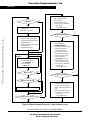
The flowchart explaining the principle of BLDC commutation control with
back-EMF zero crossing sensing is shown in Figure 17.
COMMUTATION DONE
Freescale Semiconductor, Inc...
BEMF ZERO CROSSING
DETECTED BETWEEN PREVIOUS
COMMUTATIONS?
NO
CORRECTIVE CALCULATION 1.
YES
SERVICE OF COMMUTATION:
PRESET COMMUTATION
WAIT FOR PER_TOFF UNTIL PHASE
CURRENT DECAYS TO ZERO
BEMF ZERO CROSSING
MISSED?
BEMF ZERO CROSSING MISSED
CORRECTIVE CALCULATION 2
CORRECTED SETTING
OF COMMUTATION TIME
YES
NO
BEMF ZERO CROSSING
DETECTED?
YES
SERVICE OF RECEIVED BEMF
ZERO CROSSING:
CORRECTED SETTING
OF COMMUTATION TIME
NO
NO
HAS COMMUTATION
TIME EXPIRED?
HAS COMMUTATION
TIME EXPIRED?
NO
YES
YES
MAKE MOTOR COMMUTATION
Figure 17. BLDC Commutation with Back-EMF
Zero Crossing Sensing Flowchart
Sensorless BLDC Motor Control on MC68HC908MR32
MOTOROLA
Software Description
For More Information On This Product,
Go to: www.freescale.com
19
Freescale Semiconductor, Inc.
AN2355/D
Running —
Commutation Time
Calculation
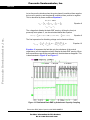
Commutation time calculation is shown in Figure 18.
T_Cmt[n-2]
T_Cmt[n-1]
T2[n-3]
T2[n-2]
n-1
n-2
T_Cmt[n]
T2[n-1]
T2[n]
n
2*Per_ZCrosFlt[n-1]
COMMUTATION IS PRESET
Freescale Semiconductor, Inc...
ZERO CROSSING
DETECTION SIGNAL
Per_ZCros[n]
COMMUTATED AT PRESET TIME NO
BACK-BMF FEEDBACK WAS RECEIVED
CORRECTIVE CALCULATION 1.
T_Cmt*[n+1]
ZERO CROSSING
DETECTION SIGNAL
Per_ZCros[n-2]
Per_ZCros0[n] =
Per_ZCros[n-1]
Per_HlfCmt[n]
Per_ZCros[n]
T_ZCros[n-1]
BACK-EMF FEEDBACK
RECEIVED AND EVALUATED
T_ZCros[n]
Per_Toff[n]
T_Cmt**[n+1]
COMMUTATED WHEN BACK-EMF
ZERO CROSSING IS MISSED
CORRECTION CALCULATION 2.
ZERO CROSSING
DETECTION SIGNAL
Per_ZCros[n]
Per_HlfCmt[n]
Figure 18. BLDC Commutation Time with Zero Crossing Sensing
The following calculations are made to calculate the commutation time
(T2[n]) during the Running state:
•
Service of commutation — The commutation time (T2[n]) is
predicted:
T2[n] = T_Cmt[n] + 2*Per_ZCrosFlt[n-1]
If 2*Per_ZCrosFlt>Per_Cmt_Max
then result is limited at Per_Cmt_Max
•
Service of received back-EMF zero crossing — The commutation
time (T2*[n]) is evaluated from the captured back-EMF zero crossing
time (T_ZCros[n]):
Per_ZCros[n] = T_ZCros[n] - T_ZCros[n-1] = T_ZCros[n] - T_ZCros0
Per_ZCrosFlt[n] = (1/2*Per_ZCros[n]+1/2*Per_ZCros0)
HlfCmt[n] = 1/2*Per_ZCrosFlt[n]- Advance_angle =
= 1/2*Per_ZCrosFlt[n]- C_CMT_ADVANCE*Per_ZCrosFlt[n]=
Sensorless BLDC Motor Control on MC68HC908MR32
20
Software Description
For More Information On This Product,
Go to: www.freescale.com
MOTOROLA
Freescale Semiconductor, Inc.
AN2355/D
Control Technique
Coef_HlfCmt*Per_ZCrosFlt[n]
The best commutation was get with Advance_angle:
60Deg*1/8 = 7.5Deg
which means Coef_HlfCmt = 0.375 at Running state
with default s/w setting
Per_Toff[n+1] = Per_ZCrosFlt*Coef_Toff and Per_Dis minimum
Coef_Toff = 0.375 at Running state, Per_Dis = 150
with default s/w setting
Per_ZCros0 <-- Per_ZCros[n]
T_ZCros0 <-- T_ZCros[n]
T2*[n] = T_ZCros[n] + HlfCmt[n]
Freescale Semiconductor, Inc...
•
If no back-EMF zero crossing was captured during preset commutation
period (T2P[n] then Corrective Calculation 1. is made:
T_ZCros[n] <-- CmtT[n+1]
Per_ZCros[n] = T_ZCros[n] - T_ZCros[n-1] = T_ZCros[n] - T_ZCros0
Per_ZCrosFlt[n] = (1/2*Per_ZCros[n]+1/2*Per_ZCros0)
HlfCmt[n] = 1/2*Per_ZCrosFlt[n]-Advance_angle =
Coef_HlfCmt*Per_ZCrosFlt[n]
The best commutation was get with Advance_angle:
60Deg*1/8 = 7.5Deg
which means Coef_HlfCmt = 0.375 at Running state!
Per_Toff[n+1] = Per_ZCrosFlt*Coef_Toff and Per_Dis minimum
Per_ZCros0 <-- Per_ZCros[n]
T_ZCros0 <-- T_ZCros[n]
•
If back-EMF zero crossing is missed then Corrective Calculation 2. is
made:
T_ZCros[n] <-- CmtT[n]+Toff[n]
Per_ZCros[n] = T_ZCros[n] - T_ZCros[n-1] = T_ZCros[n] - T_ZCros0
Per_ZCrosFlt[n] = (1/2*T_ZCros[n]+1/2*T_ZCros0)
HlfCmt[n] = 1/2*Per_ZCrosFlt[n]-Advance_angle =
Coef_HlfCmt*Per_ZCrosFlt[n]
The best commutation was get with Advance_angle:
60Deg*1/8 = 7.5Deg
which means Coef_HlfCmt = 0.375 at Running state!
Per_ZCros0 <-- Per_ZCros[n]
T_ZCros0 <-- T_ZCros[n]
•
Where:
T_Cmt = time of the last commutation
T2 = Time of the Timer 2 event (for Timer Setting)
T_ZCros = Time of the last zero crossing
T_ZCros0 = Time of the previous zero crossing
Per_Toff = Period of the zero crossing off
Per_ZCros = Period between zero crossings (estimates required
commutation period)
Per_ZCros0 = Pervious period between zero crossings
Per_ZCrosFlt = Estimated period of commutation filtered
Per_HlfCmt = Period from zero crossing to commutation (half commutation)
The required commutation timing is provided by setting commutation constants
Coef_HlfCmt, COEF_TOFF.
Sensorless BLDC Motor Control on MC68HC908MR32
MOTOROLA
Software Description
For More Information On This Product,
Go to: www.freescale.com
21
Freescale Semiconductor, Inc.
AN2355/D
Starting (Back-EMF
Acquisition)
The back-EMF sensing technique enables a sensorless detection of the rotor
position; however, the drive must be first started without this feedback. This is
due to the fact that the amplitude of the induced voltage is proportional to the
motor speed. Hence, the back-EMF cannot be sensed at a very low speed and
a special start-up algorithm must be performed.
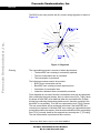
In order to start the BLDC motor, the adequate torque must be generated. The
motor torque is proportional to the multiplication of the stator magnetic flux, the
rotor magnetic flux, and the sine of the angle between these magnetic fluxes.
It implies (for BLDC motors) the following:
Freescale Semiconductor, Inc...
1. The level of phase current must be high enough.
2. The angle between the stator and rotor magnetic fields must be 90°±30°.
The first condition is satisfied during the alignment state by maintaining dc-bus
current at a level sufficient to start the motor. In the starting (back-EMF
acquisition) state, the same value of PWM duty cycle is used as the one which
has stabilized the dc-bus current during the align state.
The second condition is more difficult to fulfill without any position feedback
information. After the alignment state, the stator and the rotor magnetic fields
are aligned (0° angle). Therefore, two fast commutations (faster than the rotor
can follow) must be applied to create an angular difference in the magnetic
fields (see Figure 19).
The commutation time is defined by the start commutation period
(Per_CmtStart). This allows starting the motor such that minimal speed
(defined by state when back-EMF can be sensed) and is achieved during
several commutations, while producing the required torque. Until the back-EMF
feedback is locked, the commutation process (explained in Running) assures
that commutations are done in advance, so that successive back-EMF zero
crossing events are not missed.
After several successive back-EMF zero crossings:
•
Exact commutation time can be calculated
•
Commutation process is adjusted
•
Control flow continues to the Running state
The BLDC motor is then running with regular feedback and the speed controller
can be used to control the motor speed by changing the PWM duty cycle value.
Sensorless BLDC Motor Control on MC68HC908MR32
22
Software Description
For More Information On This Product,
Go to: www.freescale.com
MOTOROLA
Freescale Semiconductor, Inc.
AN2355/D
Control Technique
MOTOR IS RUNNING
MOTOR IS STARTING
AT STEADY-STATE CONDITION
WITH REGULAR BACK-EMF FEEDBACK
STATOR MAGNETIC FIELD
ROTOR MAGNETIC
FIELD (CREATED BY PM)
ALIGNMENT STATE
The rotor position is stabilized by
applying PWM signals to only two
motor phases
Freescale Semiconductor, Inc...
BORDER OF
STATOR POLE
ROTOR MOVEMENT
DURING ONE
COMMUTATION
ZERO CROSSING
EDGE INDICATOR
STARTING (BACK-EMF ACQUISITION)
DIRECTION OF
PHASE CURRENT
The two fast (faster then the rotor
can move) commutations are
applied to create an angular
difference of the stator magnetic
field and rotor magnetic field.
PHASE WINDING
The back-EMF feedback is tested.
When the back-EMF zero crossing is
recognized the time of new
commutation is evaluated. Until at least
two successive back-EMF zero
crossings are received the exact
commutation time can not be
calculated. Therefore, the commutation
is done in advance in order to assure
that successive back-EMF zero
crossing events would not be missed.
RUNNING
After several back-EMF zero
crossing events the exact
commutation time is calculated. The
commutation process is adjusted.
Motor is running with regular
back-EMF feedback.
Figure 19. Vectors of Magnetic Fields
Sensorless BLDC Motor Control on MC68HC908MR32
MOTOROLA
Software Description
For More Information On This Product,
Go to: www.freescale.com
23
Freescale Semiconductor, Inc.
AN2355/D
Figure 20 demonstrates the back-EMF during the start up. The amplitude of
the back-EMF varies according to the rotor speed. During the starting
(back-EMF acquisition) state the commutation is done in advance. In the
running state the commutation is done at the right moments.
PHASE BACK-EMFS
PHASE A
Freescale Semiconductor, Inc...
PHASE C
PHASE B
BACK-EMF ZERO CROSSINGS
IDEAL COMMUTATION PATTERN WHEN POSITION IS KNOWN
BTOP
CTOP
CBOT
ABOT
BTOP
ATOP
BBOT
CBOT
CTOP
ABOT
REAL COMMUTATION PATTERN WHEN POSITION IS ESTIMATED
BTOP
CBOT
FIRST
ALIGN
SECOND
BTOP
ATOP
CTOP
ABOT
BBOT
THIRD
FOURTH
CBOT
CTOP
ABOT
.................
STARTING (BACK-EMF ACQUISITION)
RUNNING
Figure 20. Back-EMF at Start Up
Sensorless BLDC Motor Control on MC68HC908MR32
24
Software Description
For More Information On This Product,
Go to: www.freescale.com
MOTOROLA
Freescale Semiconductor, Inc.
AN2355/D
Control Technique
Figure 21 illustrates the sequence of the commutations during the starting
(back-EMF acquisition) state. The commutation times T2[1] and T2[2] are
calculated without any influence of back-EMF feedback. The commutation time
calculations are explained in the following section.
T_Cmt[1]
T_Cmt[2]
T2[1]
n=1
T_Cmt[3]
T2[2]
n=2
T2[n]
n=3
2*Per_ZCrosFlt[n-1]
Freescale Semiconductor, Inc...
Per_CmtStart
2*Per_CmtStart
COMMUTATION IS PRESET
ZERO CROSSING
DETECTION SIGNAL
COMMUTATED AT PRESENT TIME
NO BACK-EMF FEEDBACK WAS RECEIVED
CORRECTIVE CALCULATION 1
T_ZCros[0]
T2*[n]
ZERO CROSSING
DETECTION SIGNAL
Per_HlfCmt[n]
COMMUTED WHEN CORRECT
BACK-EMF FEEDBACK
RECEIVED AND EVALUATED
T_ZCros[n]
T2**[n]
COMMUTATED WHEN BACK-EMF
ZERO CROSSING IS MISSED
CORRECTIVE CALCULATION 2.
ZERO CROSSING
DETECTION SIGNAL
Per_Toff[n]
Per_HlfCmt[n]
Figure 21. Calculation of the Commutation Times During the Starting
(Back-EMF Acquisition) State
Sensorless BLDC Motor Control on MC68HC908MR32
MOTOROLA
Software Description
For More Information On This Product,
Go to: www.freescale.com
25
Freescale Semiconductor, Inc.
AN2355/D
Starting —
Commutation Time
Calculation
Even the sub-states of the commutation process in the starting (back-EMF
acquisition) state remain the same as in the running state. The required
commutation timing depends on application state (starting state, running state).
So the commutation time calculation is the same as that described in
Running — Commutation Time Calculation, but the following computation
coefficients are different:
Freescale Semiconductor, Inc...
coefficient Coef_HlfCmt = 0.125 with advanced angle Advance_angle:
60Deg*3/8 = 22.5Deg
at Starting state!
Coef_Toff = 0.5 at Running state, Per_Dis = 150 with default s/w
setting
Speed Control
The speed close loop control is provided by a well known PI regulator. The
required speed is calculated from speed input variable, as explained in
Process Desired Speed Setting. The actual speed is calculated from the
average of two back-EMF zero crossing periods (time intervals), received from
the sensorless commutation control block. The speed regulator output is a
PWM duty cycle.
The speed controller works with the constant execution (sampling) period
PER_T3_RUN_US. A detailed explanation is provided in Processs Speed
Control.
Application Control
The application can be controlled in two basic modes:
•
Manual mode
•
PC master software mode
In manual mode, it is controlled by an on-board start/stop switch and speed
potentiometer. In PC master mode, it is controlled from a computer using PC
master software. In both modes, the individual variables can be observed using
the PC master software.
Sensorless BLDC Motor Control on MC68HC908MR32
26
Software Description
For More Information On This Product,
Go to: www.freescale.com
MOTOROLA
Freescale Semiconductor, Inc.
Freescale Semiconductor, Inc...
AN2355/D
Application Control
PC Master Software
PC master software was designed to provide the debugging, diagnostic, and
demonstration tools for developing algorithms and applications. It consists of
components running on PCs and parts running on the target MCU, connected
by an RS232 serial port. A small program is resident in the MCU that
communicates with the PC master software to parse commands, return status
information, and process control information from the PC. The PC master
software uses Microsoft(1) Internet Explorer as a user interface on the PC.
Communication with
PC Master Software
Specifications
SCI communication protocol with a default of 9.6 Kbaud, is used for
communication as described in User’s Manual for PC Master Software,
Motorola 2000, found on the World Wide Web at:
http://e-www.motorola.com
PC master software controls and senses the status of the application with:
•
PC master software — BLDC demonstration suitcase communication
commands
•
PC master software — BLDC demonstration suitcase communication
bytes
After reset, the BLDC control MCU software is in manual mode. In order to
control the system from PC master software, it is necessary to set PC master
software mode, and then to provide the MCU software control from PC master
software via application interface variables.
PC Master Software,
BLDC Control MCU
Software API,
Communication
Commands
Commands defined for the BLDC control MCU software are listed in Table 2.
The commands are very simple. If the software executes the command, it
responds with OK byte 00. If it is unable to execute the command, it responds
with failed code 55. The commands “Set PC master software mode”, “Set
manual mode” can only be executed when the START/STOP switch on the
demonstration suitcase is set to STOP and the motor is stopped. Otherwise, a
failed response is sent.
Table 2. PC Master Software Communication Commands
Command
Code
Data
Bytes
Demo
Suitcase Action
Set PC master
software mode
01
None
Set manual mode
02
None
Command
Respons
Byte
Response
Description
Setting of PC master
software mode
00
55
OK
Failed
Setting of manual mode
00
55
OK
Failed
1. Microsoft is a registered trademark of Microsoft Corporation in the United States and/or other
countries.
Sensorless BLDC Motor Control on MC68HC908MR32
MOTOROLA
Software Description
For More Information On This Product,
Go to: www.freescale.com
27
Freescale Semiconductor, Inc.
AN2355/D
PC Master Software,
BLDC Control MCU
Software API,
Communication
Variables
The application interface, data variables used for the exchange between the
BLDC control MCU software and PC master software, are shown in Table 3.
These variables are used for status sensing and control. PC master software
accesses these bytes directly from their physical memory addresses.
Freescale Semiconductor, Inc...
Table 3. PC Master Software API Variables
Name
Type
I/O
Representing
Range
Sys3
Sys3_Def
I/O
8flags
System variable #3
Motor_Ctrl
Motor_Ctrl_Def
I
8flags
Motor control variable
Motor_Status
Motor_Status_Def
O
8flags
Motor status variable
Failure
Failure_Def
O
8flags
Description
Failure variable
Speed input variable used for required
speed calculation
Sp_Input
U8
I
< 0; 255>
Speed_Range_Max_RPM
U16
O
< 0; 65535>
[rpm]
Speed range maximum
Speed_Max_RPM
U16
O
< 0; 65535>
[rpm]
Maximal speed limit
Speed_Min_RPM
U16
O
< 0; 65535>
[rpm]
Minimal speed limit
Commut_Rev
U8
O
< 0; 255>
Curr
S8
O
<-Curr_Range_Max_cA;
Curr_Range_Max_cA)
Curr_Range_Max_cA
S16
O
<-32768;32767>
[A*10^-2]
Commutations per motor revolution
dc-bus current
Current range maximum
[A*10^-2]
Type: S8- signed 8 bit, U8- unsigned 8 bit,S16- signed 16bit, U16- unsigned
16bit
The system registers Sys3, Motor_Ctrl, Motor_Status, Failure flags are
described by definitions of Sys3_Def, Motor_Ctrl_Def, Motor_Status_Def,
Failure_Def:
typedef union
{
struct
{
unsigned int HV
: 1; /* BIT0 High Voltage board Flag */
unsigned int LV
: 1; /* BIT1 Low Voltage board */
unsigned int EVMm : 1; /* BIT2 EVMm board */
unsigned int BIT3 : 1; /* BIT3 RESERVED */
unsigned int PCMode : 1;/* BIT4 PCMaster/manual mode Flag */
unsigned int BIT5 : 1; /* BIT5 RESERVED */
unsigned int BIT6 : 1; /* BIT6 RESERVED */
unsigned int Alignment : 1; /* BIT7 Alignment state Proceeding */
} B;
/* |Alignment|***|***|PCMode|***|EVMm|LV||HV| */
char R;
} Sys3_Def;
Sensorless BLDC Motor Control on MC68HC908MR32
28
Software Description
For More Information On This Product,
Go to: www.freescale.com
MOTOROLA
Freescale Semiconductor, Inc.
AN2355/D
Application Control
/* System register #3 Definition */
Freescale Semiconductor, Inc...
typedef union
{
struct
{
unsigned int StartCtrl : 1; /* Switch Start set to START Flag */
unsigned int BIT1
: 1; /* BIT1 RESERVED */
unsigned int BIT2
: 1; /* BIT2 RESERVED */
unsigned int BIT3
: 1; /* BIT5 RESERVED */
unsigned int BIT4
: 1; /* BIT4 RESERVED */
unsigned int BIT5
: 1; /* BIT6 RESERVED */
unsigned int BIT6
: 1; /* BIT6 RESERVED */
unsigned int ClearFail : 1; /* BIT7 Clear failure Status */
} B;
/* |ClearFail|***|***|***|***|***|***|StartCtrl| */
char R;
} Motor_Ctrl_Def;
/* PC master software Motor Control Flags Definition */
typedef union
{
struct
{
unsigned int Switch_Start : 1; /* BIT0 Switch START/STOP
set to START Flag */
unsigned int Running : 1;/* BIT1 Motor is running (Alignment, Start
or Running state) */
unsigned int BIT2 : 1; /* BIT2 RESERVED */
unsigned int V120 : 1; /* BIT3 120 V DC-Bus detected
(only for HV DC-Bus) */
unsigned int BIT4 : 1; /* BIT4 RESERVED */
unsigned int BIT5 : 1; /* BIT5 RESERVED */
unsigned int BIT6 : 1; /* BIT6 RESERVED */
unsigned int BIT7 : 1; /* BIT7 RESERVED */
} B;
/* |***|***|***|***|V120|***|Running|Switch_Start| */
char R;
} Motor_Status_Def;
/* PC master software Motor Status Flags register Definition */
typedef union
{
struct
{
unsigned
unsigned
unsigned
unsigned
unsigned
unsigned
unsigned
int
int
int
int
int
int
int
OverCurrent : 1;
OverHeating : 1;
VoltageFailure : 1;
BIT3
: 1;
BIT4
: 1;
BIT5
: 1;
BoardIdFail : 1;
/*
/*
/*
/*
/*
/*
/*
BIT0 Over-Current Failure */
BIT1 Over-Heating */
BIT2 Over-Voltage */
BIT5 RESERVED */
BIT4 RESERVED */
BIT6 RESERVED */
BIT6 pcb Identification
Failure */
/* BIT7 error Commutation */
unsigned int ErrCmt : 1;
} B;
/* |ErrCmt|***|***|***|***|VoltageFailure|OverHeating|OverCurrent| */
char R;
} Failure_Def;
/* Failure Flags register Definition */
Sensorless BLDC Motor Control on MC68HC908MR32
MOTOROLA
Software Description
For More Information On This Product,
Go to: www.freescale.com
29
Freescale Semiconductor, Inc.
AN2355/D
Table 3 declares if the variable is used as an output or input from the BLDC
control MCU software side. The variable is described and the unit defined.
When PC master software mode is set, the system start and stop is controlled
by StartCtrl flag in Motor_Ctrl variable. When the application enters the fault
state, the variable Failure displays the fault reason. Setting the ClearFail flag
in Motor_Ctrl will exit the fault state.
Freescale Semiconductor, Inc...
The Sp_Input variable is used for speed control. In PC master software mode,
it can be modified from PC master software (otherwise, it is set according to
speed potentiometer value).
Desired speed [rpm] = Sp_Input/255*(Speed_Max_RPM-Speed_Min_RPM) +
Speed_Min_RPM
So, the required motor commutation period is determined by the
Speed_Max_RPM and Speed_Min_RPM variables. These are chosen according
to which optional board and motor set by the BLDC control MCU software.
The variable Speed_Range_Max_RPM determines scaling of the speed
variables.
The actual speed of the motor can be calculated from
Per_Speed_MAX_Range and zero crossing period Per_ZCrosFlt_T2:
Actual speed [rpm] =
Speed_Range_Max_RPM*Per_Speed_MAX_Range/Per_ZCrosFlt_T2
The variable Commut_Rev can be used for calculation of the BLDC motor
commutation period:
Commutation Period [s] = 60 / Actual Speed [rpm] / Commut_Rev
The variable Curr_Range_Max_cA determines scaling of the current
variables. So, the actual dc-bus current is:
dc-bus current [A] = Curr / 256*Curr_Range_Max_cA / 100
Hardware Description
The hardware consists of the controller board accommodating
MC68HC908MR32, power stage board, and motor. It is based on modular
system boards as shown in:
•
Application note entitled Sensorless BLDC Motor Control on
MC68HC908MR32 — Software Porting to Customer Motor (Motorola
document order number AN2356)
•
Dedicated board manuals (they can be found on the Motorola web site
at http:/motorola.com/semiconductors).
Sensorless BLDC Motor Control on MC68HC908MR32
30
Software Description
For More Information On This Product,
Go to: www.freescale.com
MOTOROLA
Freescale Semiconductor, Inc.
AN2355/D
Software Description
Software Description
This section describes the design of the software blocks of the drive. The
software will be described in terms of:
•
Data Flow
•
Main Software Flowchart
•
State Diagram
Freescale Semiconductor, Inc...
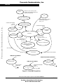
For more information on the control technique used see Control Technique.
Data Flow
The control algorithm obtains values from the user interface and sensors,
processes them and generates 3-phase PWM signals for motor control, as can
be seen on the data flow analysis shown in Figure 22 and Figure 23.
Software Variables
and Defined
Constants
Important system variables are listed in Table 4.
Table 4. Software Variables
Name
Type
Representing Range
Description
Sys1
Sys1_Def
8flags
Speed_Min_U8
U8
Sp_Input
U8
Coef_Speed_Inp
U8
Speed_Desired
U8
PIParamsScl_U8_Speed
Structure
Per_Speed_MAX_Range
U16
[UNIT_PERIOD_T2_US]
Minimal commutation period of the speed range
(at Speed_Range_Max_RPM)
Per_ZCrosFlt
U16
[UNIT_PERIOD_T2_US]
Zero crossing period — filtered
T2
U16(union)
[UNIT_PERIOD_T2_US]
Timer 2 variable
T_ZCros
U16
[UNIT_PERIOD_T2_US]
Zero crossing time [n]
T_ZCros0
U16(union)
[UNIT_PERIOD_T2_US]
Zero crossing time [n-1]
T_Cmt
U16
[UNIT_PERIOD_T2_US]
Commutation time
Curr
S8
<-Curr_Range_Max_cA;
Curr_Range_Max_cA)
dc-bus current
Curr_Align
S8
<-Curr_Range_Max_cA;
Curr_Range_Max_cA)
Required current during alignment state
PIParamsScl_S8_Currr
Structure
System variable #1
< 0; Speed_Range_Max_RPM) Minimal speed [system units]
< 0; 255>
Speed input variable used for required
speed calculation
Coeficient Sp_Inp to Speed_Desired
calculation
< 0; Speed_Range_Max_RPM) Desired speed
Speed PI regulator parameters
Current PI regulator parameters
Sensorless BLDC Motor Control on MC68HC908MR32
MOTOROLA
Software Description
For More Information On This Product,
Go to: www.freescale.com
31
Freescale Semiconductor, Inc.
AN2355/D
Table 4. Software Variables (Continued)
Name
Type
Representing Range
Description
Volt
U8
<-VOLT_RANGE_MAX;
VOLT_RANGE_MAX)
V_TASC2
U8
Back-EMF zero crossing expecting edge
V_MUX
U8
Preset value of back-EMF zero crossing
phase multiplexer
dc-bus voltage
Freescale Semiconductor, Inc...
Type: S8- signed 8 bit, U8- unsigned 8 bit, S16- signed 16bit, U16- unsigned
16bit, (union)- 16 bits access or 2*8bit access
The system registers Sys1 flags are described by definitions of Sys3_Def:
typedef union
{
struct
{
unsigned int PC_F
unsigned int Off_F
: 1;
: 1;
/* BIT0 Phase Commutation Flag */
/* BIT1 Offset timeout flag
- Offset timeout can be measured */
unsigned int ICR_F
: 1; /* BIT2 Input Capture
was succesfuly Received - Flag */
unsigned int Rmp_F : 1; /* BIT3 Speed Ramp Flag - motor ramping */
unsigned int Stop_F : 1; /* BIT4 Motor is going or is stopped */
unsigned int Strt_F : 1; /* BIT5 Start Phase Flag */
unsigned int Run_F
: 1; /* BIT6 Motor Running with
back-EMF feedback Flag */
unsigned int FOK_F
: 1; /* BIT7 Feedback within the righ time
Flag */
} B;
/* |FOK_F|Run_F|Strt_F|Stop_F|Rmp_F|ICR_F|Off_F|PC_F| */
char R;
} Sys1_Def;
/* System register #1 Definition */
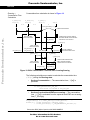
Main data flow is displayed in Figure 22. The processes are described in the
following subsections.
Process
Measurement
The process provides measurement of analog values using ADC. The
measured inputs are: dc-bus current, dc-bus voltage, and speed input. The
measurement is provided by the measurement handler. The state diagram is
explained in State Diagram.
Start/Stop Switch
Reading and
Start/Stop Decision
The process reads the start stop switch and provides start condition and clear
failure decisions, as explained in Stand-By and Fault State.
Sensorless BLDC Motor Control on MC68HC908MR32
32
Software Description
For More Information On This Product,
Go to: www.freescale.com
MOTOROLA
Freescale Semiconductor, Inc.
AN2355/D
Software Description
PC MASTER SOFTWARE
A/D CONVERTERS
TIMER 1
PCM COMMAND
PC Mode
PROCESS
SPEED INPUT, DC-BUS VOLTAGE
AND DC-BUS CURRENT MEASUREMENT
Switch_Start
Start Ctrl
Running
START/STOP
SWITCH
Freescale Semiconductor, Inc...
START/STOP SWITCH READING
AND START/STOP DECISION
Sp_Input
VOLTAGE
Stop_F
CURRENT
PROCESS
ALIGNMENT, STARTING, RUNNING
CONTROL
PROCESS
FAULT CONTROL
FAULT STOP
Volt_Max_Fault
Curr_Max_Fault
FFLAG1
FFLAG2
Figure 22. Main Data Flow — Part1
Process Fault Control
Fault Stop
The process provides fault control and fault stop as described in Fault State,
Stand-By, Align State, Back-EMF Acquisition State, and Running State.
The processes alignment, starting, and running control are displayed in
Figure 23. The processes are described in the following subsections.
Process Back, EMF
Zero Crossing
Sensing
Back-EMF zero crossing process provides:
•
Back-EMF zero crossing sampling in synchronization with PWM,
•
Evaluates the zero crossing
•
Records its time in T_ZCros
Further explanation is provided in Data Flow and Figure 27.
Sensorless BLDC Motor Control on MC68HC908MR32
MOTOROLA
Software Description
For More Information On This Product,
Go to: www.freescale.com
33
Freescale Semiconductor, Inc.
AN2355/D
Sp_Input
Speed_Min_U8
BACK-EMF
ZERO CROSSING
INPUT
TIMER 2
ACTUAL TIME
Coef_Speed_Inp
V_TASC2
CORRECTIVE CALCULATION 1
OF COMMUTATION PARAMTERS
PROCESS
DESIRED SPEED SETTING
CORRECTIVE CALCULATION 2
OF COMMUTATION PARAMETERS
(ACCELERATION)
PROCESS
BACK-EMF
ZERO CROSSING SENSING
Freescale Semiconductor, Inc...
T_CMT
*Only when regular
feedback can not
be used
ICR_F
FOK_F
T_ZCros
Speed_Desired
COMMUTATION HAS BEEN
PERFORMED — FLAG
PIParamsScl_U8_Speed
PROCESS
COMUTATION TIMES
CALCULATION
Per_Speed_MAX_Range
PC_F
T2
Per_ZCrosFlt
PROCESS
PRESET COMMUTATION
AND ZERO CROSSING
TIMER 2
PROCESS
SPEED CONTROL
PWM MODULE
VIRTUAL
TIMER 3
V_MUX
TIMER2
TIMEOUT,
ACTUAL TIME
PROCESS
ALIGNMENT CONTROL
TIMER1
INIT
Curr
Curr_Align
V_TASC2
PROCESS
SET COMMUTATION AND
ZERO CROSSING SELECTION
T_Cmt
PC_F
BACK-EMF
ZERO CROSSING
MULTIPLEXER
PIParamsScl_S8_Curr
Figure 23. Main Data Flow — Part 2: Alignment, Starting, Running Control
Sensorless BLDC Motor Control on MC68HC908MR32
34
Software Description
For More Information On This Product,
Go to: www.freescale.com
MOTOROLA
Freescale Semiconductor, Inc.
Freescale Semiconductor, Inc...
AN2355/D
Software Description
Process Commutation
Time Calculation,
Corrective
Calculation 1,
Corrective
Calculation 2
These processes provide calculations of commutation time intervals (periods)
(Per_ZCros, Per_ZCrosFlt), from captured time (T_Cmt, T_ZCros,
T_ZCros0), and sets Timer 2 with variable T2. These calculations are
described in Starting — Commutation Time Calculation and Running —
Commutation Time Calculation.
Process Desired
Speed Setting
The desired speed, held in register Speed_Desired, is calculated from the
following formula:
Speed_Desired = Sp_Input*Coef_Speed_Inp/255 + Speed_Min_U8
Processs Speed
Control
The general principle of the speed PI control loop is illustrated in Figure 24.
REFERENCE
SPEED
(Speed_Desired)
SPEED
ERROR
PWM
DUTY CYCLE
PI
CONTROLLER
(OutReg_U8)
CONTROLLED
SYSTEM
ACTUAL MOTOR
SPEED
(256*Per_Speed_MAX_Range/Per_ZCrosFlt_T2)
Figure 24. Closed Loop Control System
The speed closed loop control is characterized by the feedback of the actual
motor speed.
The actual motor speed is calculated from zero crossing period:
Actual motor speed = 256*Per_Speed_MAX_Range/Per_ZCrosFlt_T2
This information is compared with the reference set point and the error signal
is generated. The magnitude and polarity of the error signal corresponds to the
difference between the actual and desired speeds. Based on the speed error,
the PI controller generates the corrected motor voltage in order to compensate
for the error. The speed regulator parameters (gain...), internal, and
input/output variables are located in the structure PIParamsScl_U8_Speed.
The speed controller works with a constant execution (sampling) period. The
period is timed by timer 3, with the constant PER_T3_RUN_US.
PWM duty cycle is set for all six PWM channels according to regulator output,
OutReg_U8. The maximum duty cycle is at OutReg_U8 = 255. The
implementation is described in Implementation Notes — BLDC Speed
Control and Calculation.
Sensorless BLDC Motor Control on MC68HC908MR32
MOTOROLA
Software Description
For More Information On This Product,
Go to: www.freescale.com
35
Freescale Semiconductor, Inc.
AN2355/D
Process Alignment
Control
The process alignment control controls the current, Curr, using the PI regulator
during alignment state (see State Diagram). The dc-bus current is regulated to
required value Curr_Align. The current regulator parameters (gain...), internal,
and input/output variables are located in the structure PIParamsScl_S8_Curr.
Freescale Semiconductor, Inc...
The current controller works with a constant execution (sampling) period. The
period is timed by timer1, with the constant PER_CS_T1_US.
Processes
Commutation and
Zero Crossing Preset
and Set
The processes commutation and zero crossing preset and set provides the
BLDC commutation and zero crossing selection. Here the BLDC commutation
means generation of the six step commutation which creates the voltage
system shown in Figure 2. The required BLDC motor voltage system and
commutation is provided using the MC68HC08MR32 PWM block.
The zero crossing selection means the selection of the required zero crossing
phase as described in Indirect Back EMF Sensing and Back-EMF Sensing
Circuit.The zero crossing selection is provided by the multiplexer setting.
As shown in Figure 23, the commutation and back-EMF zero crossing
selection process is split into two actions:
•
Preset commutation and zero crossing selection
The preset means setting the buffered registers and RAM variables for
commutation
•
Set commutation and zero crossing selection
The setting means loading the registers with buffered variables
The implementation is described in Implementation Notes - BLDC
Commutation and Zero Crossing Selection.
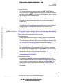
Main Software
Flowchart
The main software flowchart incorporates the main routine entered from the
reset and interrupt states. The main routine includes initializing the MCU and
the main loop. The flowcharts are shown in Figure 25, Figure 26, and
Figure 27.
MCU Initialization is entered only after system reset. It provides initialization
of system registers, ports, and CPU clock. The MCU Initialization is provided
in MCUInit() function.
After MCU Initialization the Application Initialization is executed as
AppInit() function, which performs the following actions. First the zero current
offset of the dc-bus current measurement path is calibrated. This offset on the
ADC input should be 1.65 V at zero current. This is implemented in the
hardware design, in order to be able to measure negative and positive current
values. The status registers are initialized and PWM generator is started. Also,
timer 1 is started at the right moment to be synchronized with the PWM
Sensorless BLDC Motor Control on MC68HC908MR32
36
Software Description
For More Information On This Product,
Go to: www.freescale.com
MOTOROLA
Freescale Semiconductor, Inc.
AN2355/D
Software Description
generator. This way the current measurement is executed at the defined
moment of the PWM signal.
RESET
MCU INITIALIZATION:
– SYSTEM REGISTERS INITIALIZATION
– PORTS INITIALIZATION
– PLL — CPU CLOCK INITIALIZATION
Freescale Semiconductor, Inc...
– PC MASTER SOFTWARE (PORT)
INITIALIZATION
APPLICATION INITIALIZATION:
– CURRENT OFFSET CALIBRATION
– SYSTEM REGISTERS INITIALIZATION
– PWM INITIALIZATION
– TIMER 1 CURRENT SENSING TO PWM
SYNCHRONIZATION
– ADC MEASUREMENT INITIALIZATION
MAIN S/W LOOP:
– SEE FIGURE 26
Figure 25. Main Software Flowchart
In the Stand-By state function, the start/stop switch is checked using
StSWReadStart () function. The DecideStaSto () function is called to decide if
the application should start. The start condition differs if manual or PC master
software mode is set. When in manual mode (PCMode = 0), the start condition
is the switch in the start position. When PC master software mode
(PCMode = 1), the start condition is a start request from PC master software
(StartCtrl = 1). In both modes, Stop_F is cleared when the software evaluates
the start condition. When Stop_F is cleared, the software checks the
over-voltage condition and the application starts.
The system Alignment and Starting (Back-EMF Acquisition) states are
provided by Alignment() and Start () functions in the code_start.c file, both
are called from main(). The functionality during the start and running state is
described in Sensorless Commutation Control. During the starting
(back-EMF acquisition) state, the commutation time preset calculations are
prepared in the StrtCmtPreset() function, and commutation time set
calculations are provided by the StrtCmtSet() function.
Sensorless BLDC Motor Control on MC68HC908MR32
MOTOROLA
Software Description
For More Information On This Product,
Go to: www.freescale.com
37
Freescale Semiconductor, Inc.
AN2355/D
ALIGNMENT STATE:
– TIME ALIGNMENT (TIMER3)
– APPLY VOLTAGE
NO
FAILURE
– CURRENT CONTROL LOOP
– IF STOP OR FAULT CONDITION:
STOP MOTOR
EXIT RUNNING STATE
YES
FAULT STATE:
– STOP MOTOR
– WAIT UNTIL FAULT CLEAR
YES
Freescale Semiconductor, Inc...
Stop_F Flag or Failure
APPLICATION INITIALIZATION:
NO
– CURRENT OFFSET CALIBRATION
– SYSTEM REGISTERS INITIALIZATION
STARTING (ACQUISITION) STATE:
– PWM INITIALIZATION
– PWM INCREMENT OF
– TIMER 1 CURRENT SENSING TO PWM
SYNCHRONIZATION
– STARTINCROUTREGS8
– SET SPEED REGULATOR INTEGRAL
PORTION ACCORDING TO
CUR- RENT REGULATOR
– ADC MEASUREMENT INIT.
– FIRST COMMUTATION STEP
– SECOND COMMUTATION STEP
STAND-BY
STATE:
– ACQUISITION STATE MOTOR
COMMUTATION LOOP
– IF I_CNTR_FOK SUCCESSIVE
CORRECT COMMUTATIONS:
EXIT STARTING (AQ.) STATE
– CHECK START STOP SWITCH
– IF PC MASTER S/W MODE:
CHECK STARTCTRL FLAG
– IF STOP OR FAULT CONDITION:
STOP MOTOR
EXIT RUNNING STATE
– IF RUN CONDITIONS:
SET STOP_F FLAG
Stop_F Flag
YES
YES
Stop_F Flag or Failure
NO
NO
DC-Bus over-voltage
NO
RUNNING:
YES
– SET TIMER PERIOD FOR SPEED
REGULATOR (VIRTUAL TIMER3)
– MOTOR COMMUTATION CONTROL
LOOP
– SET FAILURE.B.VOLTAGEFAILURE
– MOTOR SPEED CONTROL LOOP
Stop_F Flag or Failure
NO
– IF STOP OR FAULT CONDITION:
STOP MOTOR
EXIT RUNNING STATE
YES
Figure 26. Main Software Flowchart — Main Software Loop
Sensorless BLDC Motor Control on MC68HC908MR32
38
Software Description
For More Information On This Product,
Go to: www.freescale.com
MOTOROLA
Freescale Semiconductor, Inc.
AN2355/D
Software Description
When the start is successfully completed, the Running () function is called from
main(). During the Running state, the commutation time preset calculations
are provided by the CmtPreset() function, and commutation time set
calculations are provided by the CmtSet() function.
During the Running, Start or Alignment states, the DecideStop () function is
called to check drive stop conditions and can set the Stop_F flag. When the
stop flag is set the MotorStop () function is called to stop the motor, and
running, start, or alignment state is left. The software enters stand-by state.
Freescale Semiconductor, Inc...
Also, the commutation error (Cntr_Err>= MAX_ZC_ERR) and over-current
(OverCurrent flag = 1) fault are checked in ERRHndl () and OVCurrent ()
functions during the Running, Start or Alignment states. If any error is
detected, the function MotorStop () function is called. Then the software enters
Fault state through the Fault() function. This is only left when the failures are
cleared (variable Failure = 0). This decision is provided DecideCleSto ()
function, called from ErrorStop (). In manual control, the failures are cleared
by setting the Start/Stop switch to Stop. In case of PC master software control,
the failures are cleared by the ClearFail flag from the software. When the
failures are cleared, the software enters Application Initialization.
Besides the main loop, there are three interrupts: timer 1, timer 2, and PWM
reload interrupts. They are described in Figure 27.
Interrupt Timer 1 is periodically called with period PER_CS_T1. The interrupt
function provides dc-bus current measurement and virtual timer 3 service,
where timer 1 is providing the timer 3 time base. When over-current is
discovered, the OVC_F flag is set. Finally, the ADC is set according to the
Nxt_Chnl variable to prepare speed potentiometer or temperature sensing.
This interrupt is provided by the TIMACh1_Int() function.
Interrupt Timer 2 sets commutation actions. If commutation is enabled
(CmtE_F flag is set), the following actions are done:
•
PWM commutation step
•
Synchronization of timer 1, for current measurement with PWM
•
Phase commutated flag PC_F is set
•
Actual time (from timer counter register) = commutation time is recorded
in T_Cmt.
This interrupt is provided by the TIMACh3_Int() function.
Interrupt PWM Reload provides back-EMF zero crossing sensing. The zero
crossing input is sampled 2 or 3 times. The back-EMF state value is compared
with expecting (rising/falling) edge. If the value corresponds with expecting
edge, the zero crossing get flag ICR_F is set, and the actual time (from timer
counter register) = zero crossing time is recorded in T_ZCros. This interrupt is
provided by PWMMC_Int() function in code_isr.c.
Sensorless BLDC Motor Control on MC68HC908MR32
MOTOROLA
Software Description
For More Information On This Product,
Go to: www.freescale.com
39
Freescale Semiconductor, Inc.
AN2355/D
INTERRUPT
PWM RELOAD
INTERRUPT
TIMER 1 (TIM A CH1)
BEMF ZERO CROSSING
SENSING ISR:
CURRENT MEASUREMENT ISR:
– START ADC DC-BUS CURRENT CHANNEL
SENSE ZERO CROSSING INPUT:
– SERVE VIRTUAL TIMER3
– TAKE 3 ZC INPUT SAMPLES
– CURR = VALUE FROM ADC
– BEMF STATE = S1&S2 | S2&S3
– IF CURR > CURR_MAX_FAULT:
SET OVC_F (OVERCUR.) FLAG
Freescale Semiconductor, Inc...
– SET NEXT ADC CHANNEL NXT_CHNL
BEMF state
0
RTI
1
YES
NO
INTERRUPT
TIMER 2 (TIM A CH3)
V_TASC = fal. edge
V_TASC = ris. edge
YES
NO
COMMUTATION ISR:
SET ZERO CROSSING GET:
– SET ICR_F - ZERO CROS. GET
– T_ZCROS = TIMER2 TIME
– IF CMTE_F (COMMUTATION ENABLED):
DO MOTOR COMMUTATION STEP
TIMER 1 CURRENT SENSING TO
PWM SYNCHRONIZATION
SET PC_F (PHASE COMMUTATED)
T_CMT = TIMER 2 ACTUAL TIME
– ZERO CROSSING SELECTION
RTI
RTI
Figure 27. Software Flowchart — Interrupts
Sensorless BLDC Motor Control on MC68HC908MR32
40
Software Description
For More Information On This Product,
Go to: www.freescale.com
MOTOROLA
Freescale Semiconductor, Inc.
AN2355/D
Software Description
State Diagram
The motor control application can be in one of the eight states shown in
Figure 28. Each of these states is described in the subsections following the
figure.
RESET
INITIALIZE
MCU
Freescale Semiconductor, Inc...
INITIALIZE
APPLICATION
RUN CONDITION
(START SWITCH IS ON
AND PCMode = 0
OR PCMode AND StartCtrl
AND SWITCH IS ON)
STAND-BY STATE
PWM DISABLED
(Stop_F = 0)
CLEAR FAILURE
(START SWITCH SET OFF
OR PCMode AND CLEAR FAIL)
(FAILURE = 0)
ALIGN STATE
PWM ENABLED
OVER CURRENT
ALIGN TIMEOUT EXPIRED
IRRECOVERABLE
COMMUTATION
ERROR
BACK-EMF ACQUISITION STATE
COMMUTATION + PWM ENABLED
FAULT
STATE
PWM
DISABLED
COMMUTATION IS LOCKED
WITH BACK-EMF FEEDBACK
RUNNING STATE
COMMUTATION + PWM ENABLED
MOTOR STOP IS REQUIRED
(Stop_F = 1)
OVER VOLTAGE
STOP STATE
PWM DISABLED
DONE
Figure 28. Application State Transitions
Sensorless BLDC Motor Control on MC68HC908MR32
MOTOROLA
Software Description
For More Information On This Product,
Go to: www.freescale.com
41
Freescale Semiconductor, Inc.
AN2355/D
Initialize MCU
This state is entered after the MCU is reset, and performs the following actions:
•
MCU ports are configured for the application
•
Some application (system) variables are initialized
•
MCU clock PLL is locked
•
Hardware boards used are identified, and parameters initialized
•
PC master communication software is initialized with SCI port
•
ADC is initialized
Freescale Semiconductor, Inc...
and the state is exited.
Initialize Application
This state is used as an application reset, called following a return from fault or
stop states.
In this state the following actions are done:
•
Current measurement path calibrated and checked for error
•
Some application (system) variables initialized
•
Some MCU peripherals are configured (timer, OC function, PWM)
•
PWM outputs for motor control are turned OFF
•
Timer 1 (Tim A Ch1) is synchronized with the PWM cycle
•
Speed input, dc-bus voltage and temperature measurement is initialized
•
Ready LED is turned ON
and the state is exited.
Stand-By
State diagram for this software is shown in Figure 29.
Current measurement and current calibration when PWM is OFF
Before testing of the start switch, dc-bus current is measured when PWM is
OFF. This way the dc-bus current measurement path is calibrated. The
calibrated value Offset0_Curr is used for the final current calculation.
This offset on the ADC input should ideally be 1.65 V at 0 dc-bus current.
If the sensed value exceeds the limit (Offset_Max_Curr) when PWM is OFF,
this indicates some hardware error, and the control flow enters into the fault
state:
Start condition test
The start condition is tested. If in manual mode (PCMode = 0), the start
condition is a movement in the switch from stop to start. In PC master
software mode (PCMode = 1), the start condition in switch start position and
StartCtrl = 1. If start condition valid then Strt_F is set, Stop_F is cleared, and
the next state entered.
Sensorless BLDC Motor Control on MC68HC908MR32
42
Software Description
For More Information On This Product,
Go to: www.freescale.com
MOTOROLA
Freescale Semiconductor, Inc.
AN2355/D
Software Description
ENTER
CURRENT MEASUREMENT
AND
CURRENT CALIBRATION
WHEN PWM IS OFF
CURRENT IS HIGHER THAN LIMIT
ERROR IN HARDWARE
Freescale Semiconductor, Inc...
DONE
START CONDITION TEST
FAULT STATE
START CONDITION
(START SWITCH CHANGED
FROM STOP TO START OR
START AND PC MODE AND START CTRL)
OVER VOLTAGE
OR
UNDER VOLTAGE
SPEED INPUT
AND
DC-BUS VOLTAGE
MEASUREMENTS
DONE
EXIT
Figure 29. Stand-by State
Speed input and dc-bus voltage measurements
The dc-bus voltage is measured after the start switch is turned ON. This
prevents the measurement being disturbed by the power turn ON. Where
that dc-bus voltage is not within the limits, the control flow enters into the
fault state.
Sensorless BLDC Motor Control on MC68HC908MR32
MOTOROLA
Software Description
For More Information On This Product,
Go to: www.freescale.com
43
Freescale Semiconductor, Inc.
AN2355/D
Align State
In the align state the rotor position is stabilized by applying PWM signals to only
two motor phases (no commutation). When preset time-out expires, then this
state is finished. See Figure 30.
ENTER
RUN CONDITION
(STOP_F = 0)
CURRENT MEASUREMENT
IS DONE
Freescale Semiconductor, Inc...
CURRENT CONTROLLER
ALIGN TIME-OUT
(CMD_F = 1)
SCHEDULER
(CMD_F = 0)
OVER-CURRENT
DETECTION
ALIGN TIME-OUT EXPIRED
IRRECOVERABLE OVER-CURRENT
FAULT
STATE
EXIT
TIMER1 (TIM A CH1) INTERRUPT
CURRENT MEASUREMENT
CURRENT MEASUREMENT
IS DONE (CMD_F = 1)
ISR
DONE
Figure 30. Align State
Scheduler
The scheduler handles the state transitions in the align state. The dc-bus
current measurement is done in OC interrupt service routine, in order to
keep synchronization with PWM cycle. After measurement is made, the
scheduler allows calculation by the current controller and the over-current
detection. The CMD_F (current measurement done) flag indicates that the
new value of dc-bus current is ready to be processed by the current
controller.
The time-out (software timer 3) of this state is defined in the software by the
constants: PER_T_ALIGN and PER_BASE_T3_ALIGN.
Sensorless BLDC Motor Control on MC68HC908MR32
44
Software Description
For More Information On This Product,
Go to: www.freescale.com
MOTOROLA
Freescale Semiconductor, Inc.
AN2355/D
Software Description
Current Controller
The current controller subroutine is called every PER_CS_T1_US µs
(128 µs with default software setting) after a new value of the dc-bus current
has been obtained (CMD_F=1). It sets all six PVALx register pairs to get the
right PWM ratio for the required current.
Freescale Semiconductor, Inc...
Timer 1 Interrupt
Once the synchronization of OC function with the PWM cycle has been
achieved, it must be maintained because the current measurement is
initiated here.
Over-Current Detection
The dc-bus current is periodically sensed and the over-current condition is
evaluated. After a defined number successive over-current events
I_CNTR_OVC, the control flow enters into the fault state.
Back-EMF Acquisition
State
The back-EMF acquisition state provides the functionality described in Starting
(Back-EMF Acquisition) and Starting — Commutation Time Calculation.
Figure 31 shows the state transitions for the state.
First Commutation
After the align state time out expires, voltage is applied to another phase
pair. The first commutation is made and the PWM duty cycle is constant.
This value has been defined by the current controller during the Aalign state.
The calculation of the commutation time is explained in Starting —
Commutation Time Calculation.
Second Commutation
The commutation time (T2) is calculated from the previous commutation
time and the start commutation period (Per_CmtStart). This time is set to
timer 2. Then, the new PWM multiplexer logic data is readied for when the
commutation interrupt performs the next commutation.
The calculation of the commutation time is explained in Starting —
Commutation Time Calculation.
Measurements Handler
As explained in Scheduler and Over-Current Detection, the dc-bus
current is scanned and over-current condition is evaluated. Where there is
an over-current, the control enters the fault state (see Fault State). The
voltage and the speed commands are scanned too. When this state is
finished, the values of dc-bus current, dc-bus voltage, and speed command
are updated.
Sensorless BLDC Motor Control on MC68HC908MR32
MOTOROLA
Software Description
For More Information On This Product,
Go to: www.freescale.com
45
Freescale Semiconductor, Inc.
AN2355/D
PWM DUTY CYCLE IS LEFT AT VALIE
FOUND BY THE CURRENT CONTROLLER
DURING THE ALIGN STATE
ENTER
EXIT
FIRST COMMUTATION
COMMUTATIONS ARE LOCKED TO
THE BACK-BMF FEEDBACK
(START_F = 0)
Freescale Semiconductor, Inc...
DONE
CURRENT MEASUREMENT
IS DONE
(CMD_F = 1)
SECOND COMMUTATION
CURRENT MEASUREMENT
IS DONE
DONE
DONE
MEASUREMENTS
HANDLER
DONE
SCHEDULER
ERROR HANDLER
MEASUREMENTS
HANDLER
(CMD_F = 1)
DONE
DONE
PHASE HAS BEEN
COMMUTATED (PC_F=1)
RECEIVED THE
ZERO CROSSING EVENT
(ICR_F = 1)
DONE
DONE
SERVICE OF COMMUTATION
SERVICE OF RECEIVED
BACK-EMF ZERO CROSSING
FEEDBACK
OVER-CURRENT
IRRECOVERABLE COMMUTATION ERROR
FAULT STATE
IRRECOVERABLE OVER-CURRENT
TIMER2 (TIM A CH3) INTERRUPT
PWM (RELOAD) INTERRUPT (PWM CENTER)
COMMUTATION ISR
TIMER1 (TIM A CH1) INTERRUPT
PHASE HAS BEEN
COMMUTATED
(PC_F=1)
CURRENT MEASUREMENT
ISR
CURRENT MEASUREMENT
IS DONE
(CMD_F = 1)
BEMF ZERO CROSSING
SENSING ISR
DONE
(ICR_F=1)
Figure 31. Back-EMF Acquisition
Sensorless BLDC Motor Control on MC68HC908MR32
46
Software Description
For More Information On This Product,
Go to: www.freescale.com
MOTOROLA
Freescale Semiconductor, Inc.
AN2355/D
Software Description
Service of Commutation
As already explained, the motor phase commutation is performed in the OC
interrupt service routine. The phase commutated flag (PC_F=1) indicates
this action to the scheduler, which allows the performed commutation to be
serviced. Detailed explanation of this state is in Processes Commutation
and Zero Crossing Preset and Set.
Freescale Semiconductor, Inc...
Service of Received Back-EMF Zero Crossing
The back-EMF zero crossing is detected by PWM middle function block.
Then the appropriate flag (captured received the zero crossing event ICR_F) is set by PWM centre interrupt service routine. This indicates to the
scheduler that the zero crossing event must be served.
The following actions are taken:
1. Commutation parameters are recalculated more precisely based on
the received feedback
2. Commutation time is preset to the output compare register of timer 2
For a better understanding of how the commutation process works, see
Sensorless Commutation Control, (see Starting — Commutation Time
Calculation).
BEMF Zero Crossing Sensing Interrupt Service Routine
This ISR is used to evaluate the back-EMF zero crossing. Back-EMF is
evaluated here in order to synchronize zero crossing capture with the middle
of central-aligned PWM. This technique rejects the noise caused by PWM
from the back-EMF signal. When this ISR is initiated, then three samples of
the zero crossing input (BEMF_IN) are taken and the state is evaluated.
Based on the expected edge (V_TASC2, ELS2A_ELS2B) and the
evaluated state of the BEMF_IN pin, the zero crossing event is verified. If it
is accepted, then the captured time is stored in variable (T_ZCros) and the
PWM ISR is finished. The appropriate flag (captured received the zero
crossing event — ICR_F) is set.
Current Measurement Interrupt Service Routine
The output compare function is used to synchronize initiating the dc-bus
current sampling with the PWM cycle, and also for the commutation timing.
Error Handler
If the BLDC motor is controlled properly, commutation events must be
locked to the back-EMF zero crossing feedback. When that feedback is lost,
commutation time is derived from previous commutation events. If feedback
does not recover during a defined number of commutations (constant —
C_MaxErr), then the situation is evaluated as irrecoverable commutation
error, and the fault state is entered.
Sensorless BLDC Motor Control on MC68HC908MR32
MOTOROLA
Software Description
For More Information On This Product,
Go to: www.freescale.com
47
Freescale Semiconductor, Inc.
AN2355/D
Measurement Handler
The measurement handler assures that the measurement process is done
in the right order. The dc-bus voltage, speed command, and temperature
are scanned sequentially. After the state has run three times, all the values
for dc-bus current, dc-bus voltage, speed input, and temperature are
updated. dc-bus current is scanned with a constant time period in the current
measurement ISR, but the over-current condition is evaluated in the main
software loop. After a defined number (I_OVC_Cnt) of successive
over-current events, the control flow enters into the fault state.
Freescale Semiconductor, Inc...
Running State
The BLDC motor is run with regular feedback. The speed controller is used to
control the motor speed by changing the value of PWM duty cycle. Figure 32
shows the state transitions.
Measurements Handler
Explained in Back-EMF Acquisition State.
Service of Commutation
Explained in Back-EMF Acquisition State.
Service of Received Back-EMF Zero Crossing
Explained in Back-EMF Acquisition State. The difference is that the
commutation parameters are recalculated with different constants (see
Running — Commutation Time Calculation)
BEMF Zero Crossing Interrupt Service Routine
Explained in Back-EMF Acquisition State.
Current Measurement Interrupt Service Routine
Explained in Back-EMF Acquisition State.
Error Handler
Explained in Back-EMF Acquisition State.
Over Current
Explained in Back-EMF Acquisition State.
Sensorless BLDC Motor Control on MC68HC908MR32
48
Software Description
For More Information On This Product,
Go to: www.freescale.com
MOTOROLA
Freescale Semiconductor, Inc.
AN2355/D
Software Description
ENTER
EXIT
MOTOR STOP IS REQUIRED
(STOP_F = 1)
T3 TIME-OUT
(T3_F = 1)
SPEED CONTROL
CURRENT MEASUREMENT
IS DONE
DONE
Freescale Semiconductor, Inc...
DONE
SCHEDULER
ERROR HANDLER
MEASUREMENTS
HANDLER
(CMD_F=1)
DONE
DONE
PHASE HAS BEEN
COMMUTATED (PC_F = 1)
RECEIVED
THE ZERO CROSSING EVENT
DONE
DONE
(ICR_F = 1)
SERVICE OF COMMUTATION
SERVICE OF RECEIVED
BACK-EMF ZERO CROSSING
FEEDBACK
IRRECOVERABLE COMMUTATION ERROR
FAULT STATE
OVER-CURRENT
TIMER2 (TIM A CH3) INTERRUPT
PWM RELOAD INTERRUPT (PWM CENTER)
COMMUTATION
ISR
BEMF ZERO CROSSING
SENSING ISR
PHASE HAS BEEN
COMMUTATED (PC_F = 1)
DONE
TIMER1 (TIM A CH1) INTERRUPT
(ICR_F = 1)
CURRENT MEASUREMENT
ISR
CURRENT MEASUREMENT
IS DONE
(CMD_F = 1)
Figure 32. Running State
Sensorless BLDC Motor Control on MC68HC908MR32
MOTOROLA
Software Description
For More Information On This Product,
Go to: www.freescale.com
49
Freescale Semiconductor, Inc.
AN2355/D
Stop State
When motor stop is required, the PWM signals are disabled and the power
switches are switched off. The state diagram for this state is shown in
Figure 33.
ENTER
MOTOR STOP IS REQUIRED
(STOP_F = 1)
Freescale Semiconductor, Inc...
TIMER1 (TIM A CH1) INTERRUPT
MOTOR IS STOPPED
PWM IS OFF
CURRENT MEASUREMENT
ISR
CURRENT MEASUREMENT
IS DONE
(CMD_F=1)
EXIT
Figure 33. STOP State
Sensorless BLDC Motor Control on MC68HC908MR32
50
Software Description
For More Information On This Product,
Go to: www.freescale.com
MOTOROLA
Freescale Semiconductor, Inc.
AN2355/D
Software Description
Fault State
If over-voltage, over-current, or commutation fault occurs, the motor control
PWM’s are disabled and control enters the fault state, where it remains until
RESET or clear failure (start switch set OFF or PCMode&ClearFail). The fault
state is indicated by the Red LED diode blinking.
Clear Failure Test
The failure (Failure = 0) is tested. In manual mode (PCMode = 0), the switch
in the stop position clears the failure. In PC master software mode
(PCMode = 1), the failure is cleared by ClearFail flag or the switch in the stop
position. If start condition is valid Strt_F is set, Stop_F is cleared, and the
next state entered.
Freescale Semiconductor, Inc...
See Figure 34.
ENTER
TIMER1 (TIM A CH1) INTERRUPT
MOTOR IS STOPPED
PWM IS OFF
WAIT FOR
CLEAR FAILURE
OR RESET
DONE
CURRENT MEASUREMENT
ISR
CURRENT MEASUREMENT
IS DONE
(CMD_F = 1)
CLEAR FAILURE TEST
ERROR INDICATION
(RED LED IS BLINKING)
CLEAR FAILURE
(START SWITCH SET OFF OR
PCMODE&CLEARFAIL)
(FAILURE = 0) OR RESET
Figure 34. Fault State
Sensorless BLDC Motor Control on MC68HC908MR32
MOTOROLA
Software Description
For More Information On This Product,
Go to: www.freescale.com
51
Freescale Semiconductor, Inc.
AN2355/D
Freescale Semiconductor, Inc...
Implementation Notes
Software Files
The software files and structure are described in an application note entited
Sensorless BLDC Motor Control on MC68HC908MR32 — Software Porting to
Customer Motor (Motorola document order number AN2356/D).
BLDC Commutation
and Zero Crossing
Selection
The required BLDC motor voltage system commutation is provided using the
MC68HC08MR32 PWM block.
The zero crossing selection is provided by setting port F pins PTF1–PTF3
connected to the multiplexer.
As shown in Data Flow, the commutation and back-EMF zero-crossing
selection process is split into two actions:
1. Preset BLDC commutation and BEMF zero-crossing selection
2. Set BLDC commutation and BEMF zero-crossing selection
Preset BLDC
Commutation and
BEMF Zero Crossing
Selection
In each phase of the 6-step commutation two PWM channels (bottom and top
switch) are active and the other four PWM channels are logical 0. The
commutation preset is accomplished by setting the buffered registers PVAL1H,
PVAL1L through PVAL6H, PVAL6L. To preset the active PWM channel, the
MSB bits of the dedicated PVALxH registers are set to 0.To preset the PWM
channel to the logical 0, the MSB bits of the dedicated PVALxH registers are
set to 1. This is due to the signature bit functionality as described in
68HC908MR32, 68HC9908MR16 Advance Information (Motorola document
order number MC68HC908MR32/D) .This commutation preset is provided by
the function Commut (). In Commut(), the function field
Set_PWM(P_Step_Cmt] () calls one of Shft_PWM0..5() functions according to
P_Step_Cmt value, so the PVALxH registers are set as required. This will not
effect the PWM signals until LDOK bit is set. Also, the back-EMF zero crossing
selection preset is provided in this function, by setting V_MUX variable
according to P_Step_Cmt value.
Set BLDC
Commutation and
BEMF Zero Crossing
Selection
The commutation set is provided in timer 2 interrupt function TIMACh3_Int() in
the code_isr.c file. The PWMEN is toggled and LDOK bit set, in order to
immediately restart the PWM generator and reload the PWM with the buffered
PVAL1H, PVAL1L through PVAL6H, PVAL6L registers. Then the back-EMF
zero crossing selection set is provided by setting PORTF according to V_MUX
variable.
Sensorless BLDC Motor Control on MC68HC908MR32
52
Software Description
For More Information On This Product,
Go to: www.freescale.com
MOTOROLA
Freescale Semiconductor, Inc.
AN2355/D
Implementation Notes
BLDC Speed Control
and Calculation
Desired speed calculation and PWM duty cycle setting is quite simple, but there
are some C language syntax tricks. Also, the scaling aspect needs to be taken
into consideration.
Desired Speed
Calculation
The 8 bit value Speed_Desired is calculated using 8-bit multiplication of two
8-bit variables, Sp_Input and Coef_Speed_Inp. The syntax is:
(unsigned char)((Sp_Input*Coef_Speed_Inp)>>8)
This syntax is used to generate optimal code using the MUL instruction.
Freescale Semiconductor, Inc...
PWM Duty Cycle
PWM duty cycle is set for all six PWM channels according to regulators output
OutReg_U8. The maximal duty cycle is at OutReg_U8 = 255. The registers
PVAL1H, PVAL1L through PVAL6H, PVAL6L are set proportionally to the
PWM modulus register PMOD = MCPWM_MODULUS constant (100% duty
cycle is when PVALx = PMOD).
The PWM_Val_Max variable is:
PWM_Val_Max = DUTY_PWM_MAX*MCPWM_MODULUS
This variable is used for scaling of the regulator output OutReg_U8. The
registers PVAL1H, PVAL1L through PVAL6H, PVAL6L are loaded with
PWM_Val calculated from OutReg_U8:
PWM_Val = PWM_Val_Max*OutReg_U8/256
This calculation is provided with macro umul_16x8_macro.
Timers
Timer 1 and timer 2 are implemented using MC68HC08MR32 timers. Timer 3
is a software virtual timer using time base of timer 1.
Timer 1
Timer 1 is provided by timer A channel 1 set in output compare mode. In this
mode the registers TACH1H and TACH1L are used for setting the output
compare value, T1.
•
TACNTH and TACNTL form a 16-bit timer A counter with an infinite
counting 16-bit roll over.
•
The timer A channel 1 interrupt is called whenever TACH1H = TACNTH
and TACH1L = TACNTL. With each interrupt, the registers TACH1H and
TACH1L are loaded with the new value, T1 = T1+PER_CS_T1, where
T1+PER_CS_T1 is a 16-bit addition with no saturation. So, the constant
interrupt period PER_CS_T1 of the timer T1 interrupts is generated.
•
The timer unit UNIT_PERIOD_T1_US of timer A is determined by the
MCU bus frequency (8 MHz with a 4-MHz oscillator and default software
setting) and timer prescaler set in TASC. So, the default software value
is 2 µs. The timer 1 interrupt function is provided by the TIMACh1_Int ()
function.
Sensorless BLDC Motor Control on MC68HC908MR32
MOTOROLA
Software Description
For More Information On This Product,
Go to: www.freescale.com
53
Freescale Semiconductor, Inc.
AN2355/D
Freescale Semiconductor, Inc...
Timer 2
Timer 2 is provided by timer A channel 3 set in output compare mode. In this
mode, the registers TACH3H and TACH3L are used for setting the output
compare value, T2.
•
TACNTH and TACNTL form a 16-bit timer A counter, with infinite
counting 16-bit roll over.
•
The actual time is sensed from TACNTH and TACNTL base (e.g., time
of the commutation, T_Cmt).
•
The timer A channel 3 (timer 2) interrupt is called whenever TACH3H =
TACNTH and TACH3L = TACNTL. So, the registers TACH3H and
TACH3L are loaded with the T2 variable value.
•
The value T2 (e.g., T2 = T_Cmt + Per_HlfCmt) is calculated using a
16-bit addition with no saturation. So, the time duration up to 65,536
UNIT_PERIOD_T2_US from actual time (TACNTH, TACNTL) can be
timed at any TACNTH, TACNTL timer A counter value.
•
The timer unit UNIT_PERIOD_T2_US of timer A is determined by the
MCU bus frequency (8 MHz with 4-MHz oscillator and default software
setting) and timer prescaler set in TASC. So, the default software value
is 2 µs. The timer 2 interrupt function is provided by function
TIMACh3_Int().
References
1. Sensorless BLDC Motor Control on MC68HC908MR32 - Software
Porting to Customer Motor (document order number AN2356/D),
Motorola 2002
2. Motion Control Development Tools found on the World Wide Web at:
http://e-www.motorola.com
3. Motorola Embedded Motion Control MC68HC908MR32 Control Board
User’s Manual, (document order number MEMCMR32CBUM/D),
Motorola 2000
4. Motorola Embedded Motion Control 3-Phase AC BLDC High-Voltage
Power Stage User’s Manual (document order number
MEMC3PBLDCPSUM/D), Motorola 2000
5. Motorola Embedded Motion Control Optoisolation Board (document
order number MEMCOBUM/D), Motorola 2000
6. Motorola Embedded Motion Control Evaluation Motor Board User’s
Manual (document order number MEMCEVMBUM/D), Motorola 2000
7. Motorola Embedded Motion Control 3-Phase BLDC Low-Voltage Power
Stage User’s Manual (document order number
MEMC3PBLDCLVUM/D), Motorola 2000
Sensorless BLDC Motor Control on MC68HC908MR32
54
Software Description
For More Information On This Product,
Go to: www.freescale.com
MOTOROLA
Freescale Semiconductor, Inc.
AN2355/D
References
8. User’s Manual for PC Master Software, Motorola 2000, found on the
World Wide Web at:
http://e-www.motorola.com
9. 68HC908MR32, 68HC908MR16 Advance Information (document order
number MC68HC908MR32/D), Motorola
Freescale Semiconductor, Inc...
10. Low Cost High Efficiency Sensorless Drive for Brushless DC Motor
using MC68HC(7)05MC4 (document order number AN1627), Motorola
Sensorless BLDC Motor Control on MC68HC908MR32
MOTOROLA
Software Description
For More Information On This Product,
Go to: www.freescale.com
55
Freescale Semiconductor, Inc.
AN2355/D
HOW TO REACH US:
USA/EUROPE/LOCATIONS NOT LISTED:
Motorola Literature Distribution;
P.O. Box 5405, Denver, Colorado 80217
1-303-675-2140 or 1-800-441-2447
JAPAN:
Motorola Japan Ltd.; SPS, Technical Information Center,
3-20-1, Minami-Azabu Minato-ku, Tokyo 106-8573 Japan
81-3-3440-3569
Freescale Semiconductor, Inc...
ASIA/PACIFIC:
Information in this document is provided solely to enable system and software
Motorola Semiconductors H.K. Ltd.;
Silicon Harbour Centre, 2 Dai King Street,
Tai Po Industrial Estate, Tai Po, N.T., Hong Kong
852-26668334
TECHNICAL INFORMATION CENTER:
implementers to use Motorola products. There are no express or implied copyright
licenses granted hereunder to design or fabricate any integrated circuits or
integrated circuits based on the information in this document.
Motorola reserves the right to make changes without further notice to any products
herein. Motorola makes no warranty, representation or guarantee regarding the
1-800-521-6274
suitability of its products for any particular purpose, nor does Motorola assume any
HOME PAGE:
liability arising out of the application or use of any product or circuit, and specifically
http://motorola.com/semiconductors
disclaims any and all liability, including without limitation consequential or incidental
damages. “Typical” parameters which may be provided in Motorola data sheets
and/or specifications can and do vary in different applications and actual
performance may vary over time. All operating parameters, including “Typicals”
must be validated for each customer application by customer’s technical experts.
Motorola does not convey any license under its patent rights nor the rights of
others. Motorola products are not designed, intended, or authorized for use as
components in systems intended for surgical implant into the body, or other
applications intended to support or sustain life, or for any other application in which
the failure of the Motorola product could create a situation where personal injury or
death may occur. Should Buyer purchase or use Motorola products for any such
unintended or unauthorized application, Buyer shall indemnify and hold Motorola
and its officers, employees, subsidiaries, affiliates, and distributors harmless
against all claims, costs, damages, and expenses, and reasonable attorney fees
arising out of, directly or indirectly, any claim of personal injury or death associated
with such unintended or unauthorized use, even if such claim alleges that Motorola
was negligent regarding the design or manufacture of the part.
Motorola and the Stylized M Logo are registered in the U.S. Patent and Trademark
Office. digital dna is a trademark of Motorola, Inc. All other product or service
names are the property of their respective owners. Motorola, Inc. is an Equal
Opportunity/Affirmative Action Employer.
© Motorola, Inc. 2002
AN2355/D
Rev. 0
11/2002
For More Information On This Product,
Go to: www.freescale.com