1
EUROPEAN SOUTHERN OBSERVATORY
Organisation Européenne pour des Recherches Astronomiques dans l'Hemisphère Austral
Europäische Organisation für astronomische Forschung in der südlichen Hemisphäre
ESO - EUROPEAN SOUTHERN OBSERVATORY
Karl-Schwarzschild-Straße 2 . D-85748 Garching bei München
VLT INSTRUMENTATION
PULPO-2 Manual
VLT-TRE-ESO-13630-3490
Issue 1.0
Date: 07/12/2004
Prepared by:
Claudio Cumani
Christoph Geimer
Nicolas Haddad
Bernhard Lopez
Javier Reyes
Javier Valenzuela
Approved by:
Dietrich Baade
Released by:
Alan Moorwood
ESO
VLT Instrumentation
Pulpo 2 Manual
Doc.
Issue
Date
Page
VLT-TRE-ESO-13630-3490
1.0
07/12/2004
2 of 76
Change Record
Issue/Rev
Date
1.0
07/12/2004
Section/Page affected
Reason
All
First issue
ESO
VLT Instrumentation
Pulpo 2 Manual
Doc.
Issue
Date
Page
VLT-TRE-ESO-13630-3490
1.0
07/12/2004
3 of 76
TABLE OF CONTENTS
1
INTRODUCTION ...................................................................................................4
1.1 Purpose...........................................................................................................4
1.2 Applicable documents .....................................................................................4
1.3 Reference documents .....................................................................................4
1.4 Abbreviations and acronyms...........................................................................4
1.5 Glossary ..........................................................................................................5
1.6 Stylistic conventions........................................................................................5
1.7 Naming conventions .......................................................................................6
1.8 Acknowledgments ...........................................................................................6
2 OVERVIEW ...........................................................................................................7
3 HOUSING..............................................................................................................9
4 CPU BOARD .......................................................................................................10
4.1 Functional overview ......................................................................................10
4.2 Power supply ................................................................................................12
4.3 The 486Core .................................................................................................14
5 PERIPHERAL BOARD ........................................................................................17
5.1 Functions, board format and connectors.......................................................17
5.2 Bus interface .................................................................................................19
5.3 Sensors.........................................................................................................21
5.4 Heater control ...............................................................................................24
5.5 Shutter control...............................................................................................26
5.6 Other functions..............................................................................................27
5.7 Register interface ..........................................................................................28
6 SOFTWARE ........................................................................................................34
6.1 Status bytes ..................................................................................................34
6.2 Command reply and errors ...........................................................................42
6.3 Dimensions of command and reply parameters............................................45
6.4 Commands....................................................................................................45
6.5 Commands (short list) ...................................................................................63
6.6 PID ................................................................................................................66
6.7 Logging .........................................................................................................66
6.8 Self Recovery................................................................................................67
7 DIFFERENCIES WITH PULPO ...........................................................................68
7.1 Incompatibilities ............................................................................................68
7.2 New functionalities ........................................................................................68
ANNEX A. Cable connector pinout .......................................................................69
ANNEX B. Practical Example (OmegaCam).........................................................73
ESO
Doc.
Issue
Date
Page
VLT Instrumentation
Pulpo 2 Manual
VLT-TRE-ESO-13630-3490
1.0
07/12/2004
4 of 76
1 INTRODUCTION
1.1
Purpose
This document provides a description of the functionalities and the command
interface of the Pulpo-2 ESO standard multifunctional module.
It is intended to provide the ESO hardware and software engineers who intend to
maintain or use the Pulpo-2 controller with all the necessary information to:
•
understand the Pulpo-2 hardware setting
•
operate Pulpo2 through the software command interface
Pre-requisites: knowledge of CCD camera systems operations (cooling, CCD
operation conditions, shutter) is required, therefore Pulpo-2 must be used by
experienced engineers only.
1.2
Applicable documents
The following documents, of the exact issue shown, form a part of this document to
the extent specified herein.
Reference
Document Number
[AD 01]
VLT-PRO-ESO-10000-0228
[AD 02]
VLT-PLA-ESO-00000-0006
1.3
Issue
Date
1.0
10/03/1993
2.0
21/05/1992
Title
VLT Software Programming Standards
VLT Software Management Plan
Reference documents
The following documents are referenced in this document.
Reference
[RD 01]
[RD 02]
[RD 03]
1.4
Document Number
INS-01/0044
INS-02/0018
VLT-CRE-ESO-13640-0003
Issue
Date
Title
Pulpo upgrade statement of work
Alternatives for Pulpo upgrade
Pulpo change request
Abbreviations and acronyms
This document employs several abbreviations and acronyms to refer concisely to an
item, after it has been introduced. The following list is aimed to help the reader in
recalling the extended meaning of each short expression:
BIOS
CCD
CPU
DAC
DMA
DN
DRAM
ESO
Basic Input/Output System
Charge-Coupled Devices
Central Processing Unit
Digital to Analog Converter
Direct Memory Access
Data Number
Dynamic Random Access Memory
European Southern Observatory
ESO
FFS
FIERA
GPIO
I/O
IDE
ISA
LCU
LCD
LED
MOSFET
MTBF
NAND
NOR
OS
PC
PCMCIA
PID
PLD
PWM
RAM
RTC
SLCU
SMD
UART
VLT
XTAL
1.5
VLT Instrumentation
Pulpo 2 Manual
Doc.
Issue
Date
Page
VLT-TRE-ESO-13630-3490
1.0
07/12/2004
5 of 76
Flash File System
Fast Imager Electronic Readout assembly
General-Purpose I/O
Input/Output
Integrated Device (or Drive) Electronics
Industry Standard Architecture
Local Control Unit
Liquid Crystal Display
Light-Emitting Diode
Metal Oxide Semiconductor Field-Effect Transistor
Mean Time Between Failures
Negated AND (logic)
Negated OR (logic)
Operating System
Printed Circuit
Personal Computer Memory Card International Association (also:
People Can't Memorize Computer Industry Acronyms)
Proportional/Integral/Derivative controller
Programmable Logic Device
Pulse Width Modulator
Random Access Memory
Real Time Clock
Sparc-based Local Control Unit
Surface Mounted Device
Universal Asynchronous Receiver Transmitter
Very Large Telescope
Crystal (frequency reference)
Glossary
No special definition is introduced in this manual.
1.6
Stylistic conventions
The following styles are used:
bold
in the text, for commands, filenames, pre/suffixes as they have to be typed.
italic
in the text, for parts that have to be substituted with the real content before
typing.
teletype
for examples.
<name>
in the examples, for parts that have to be substituted with the real content before
typing.
bold and italic are also used to highlight words.
ESO
1.7
VLT Instrumentation
Pulpo 2 Manual
Doc.
Issue
Date
Page
VLT-TRE-ESO-13630-3490
1.0
07/12/2004
6 of 76
Naming conventions
This implementation follows the naming conventions as outlined in [AD 01].
1.8
Acknowledgments
Special thanks to Rolf Gerdes, who contributed to the development of the Pulpo-2
project and to the first draft of some of the chapters of this manual.
ESO
VLT Instrumentation
Pulpo 2 Manual
Doc.
Issue
Date
Page
VLT-TRE-ESO-13630-3490
1.0
07/12/2004
7 of 76
2 OVERVIEW
Pulpo-2 is an ESO standard multifunctional module designed for use with cooling
systems and shutters of ESO CCD detector systems. It is able to:
•
•
•
•
•
•
•
•
Read up to 29 temperature sensors, PT100 type,
Control 8 heaters circuits of up to 7 Watts each,
Read out of a vacuum sensor,
Interface in a flexible way to a large variety of shutters
Centralize alarms from vacuum and temperature sensors,
Display parameters for easy and quick parameter check-out,
Log sensor values on internal flash disk for later recovery,
Provide a serial and an ethernet interface.
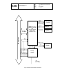
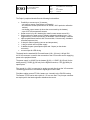
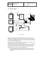
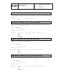
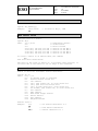
The standard Pulpo-2 consists of a CPU board, a peripheral board, the user
interface (display and buttons), the housing and the cabling inside (figure 1).
The CPU board controls the display, the input keyboard, the serial link and the
Peripheral board.
The peripheral board is the interface to the detector head, sensing the temperature
and controlling the heaters and the shutter.
With a different housing up to 3 peripheral boards could be used.
The interface between the CPU board and the Peripheral board is via an ISA bus.
ESO
VLT Instrumentation
Pulpo 2 Manual
Doc.
Issue
Date
Page
VLT-TRE-ESO-13630-3490
1.0
07/12/2004
8 of 76
Fig. 1:Overview of PULPO-II
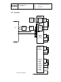
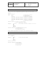
The CPU board is based on a credit-card-size embedded PC mounted on a board
containing the power supply and the connectors to the display, input keyboard and
the serial communication to the SLCU. This embedded PC is called 486Core in this
document.
As can be seen on figure 1, the connectors on the Peripheral board to interface to the
Detector Head are split in two groups. The first group of connectors offers the same
interface as the current PULPO and the second group presents the additional
sensors and heater control lines. By doing this, the current PULPO can be replaced
by the new one without changing the cabling between PULPO and the dewar. This
idea will help us in maintaining the instruments already deployed in case we need to
substitute the current PULPO by an upgraded one.
ESO
VLT Instrumentation
Pulpo 2 Manual
Doc.
Issue
Date
Page
VLT-TRE-ESO-13630-3490
1.0
07/12/2004
9 of 76
3 HOUSING
The standard housing consists of off-the-shelf aluminum profiles (kind of profiles from
the company MTS Systemtechnik) and aluminum covers. This housing combines a
good trade-off among easiness, robustness and accessibility to the internal parts.
Fig 1 - PULPO-II
With a different - wider - housing, up to 3 peripheral boards could be used.
ESO
VLT Instrumentation
Pulpo 2 Manual
Doc.
Issue
Date
Page
VLT-TRE-ESO-13630-3490
1.0
07/12/2004
10 of 76
4 CPU BOARD
4.1
Functional overview
The Pulpo-2 CPU board offers the following functionalities:
•
•
•
•
•
•
Non-volatile FLASH Disk for OS, configuration and user data ,
ISA-Bus with 16-bit Data, 16-bit address and control lines,
Power supply for on-board peripherals and the Pulpo-2 Peripheral board,
Up to 3 optoisolated serial ports and one serial fiber connection to the
SLCU,
Ethernet connection for on-site debugging and fast log data download,
Interface to the user through the front panel keyboard and display.
The Pulpo-2 CPU board has a standard Eurocard size (160x100 mm).
The core component is a tiny "486Core" PC card module (75x54mm) from
Compulab1, which hosts a complete PC with a 486 processor, on-board memory,
FLASH disk and all standard PC peripherals, e.g. serial ports, parallel port, IDE
Interface, keyboard controller, PCMCIA controller, Ethernet controller and external
interface (I/O ports, VL bus and ISA bus). For a description of the 486Core see the
dedicated chapter below.
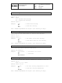
The backplane connector is a 96-pin DIN41612. This connector provides power and
ISA bus signals to the Peripheral board.
The CPU board also contains the power supply for the 486Core and the Peripheral
board. It is supplied with 24V from the FIERA power supply. The required voltages
for the 486Core (5V/3.3V) and the peripheral board (+5V, +3.3V,+15V,-15V,+24V)
are generated on the CPU board by means of DC/DC converters.
The control connection to the user (display and keyboard) is also performed through
the CPU board. The display is a Varitronix MGLS12864T-HT-LED03 with a display
size of 128x64 pixel and LED background illumination. It features an on-board
Toshiba controller (T6963), 8K-ROM with predefined character sizes of 8x8 or 8x6
pixels, and 8K RAM for user defined characters. It can operate in either text mode,
graphic mode or mixed mode.
The user input can be performed via buttons on the front panel. These buttons are
read by the 486Core via the GPIO (General Purpose I/O) lines, so there is no need
for additional circuitry.
The connection to the LCD display is via the parallel port interface due to the ease of
use and availability of the software device driver to control it.
1
See www.compulab.co.il
ESO
Doc.
Issue
Date
Page
VLT Instrumentation
Pulpo 2 Manual
VLT-TRE-ESO-13630-3490
1.0
07/12/2004
11 of 76
Com 1
Com 2
Opto isolated
Comports
Com 3 (optional)
486 Core
Keyboard control
Ethernet
Front panel
keyboard
+5V
+3.3V
Display control
+15V
VCC_RTC
+5V
RESET
Backplane
ISA-Bus
with
on board DRAM
NOR FLASH
NAND FLASH
10BaseT
VCC_LCD
-15V
+5V
+3.3V
Power
supply
+12V_Opto
+24V
+24V
from FIERA
power supply
Fig.2: Overview of the PULPO-II CPU board
Display
ESO
4.2
VLT-TRE-ESO-13630-3490
1.0
07/12/2004
12 of 76
Doc.
Issue
Date
Page
VLT Instrumentation
Pulpo 2 Manual
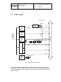
Power supply
To 486 Core
Voltage
supervis
9..32V
+5V
+5V
To 486 Core
+3.3V
9..32V
To shutter
interface
+3.3V
+12V
9..32V
VCC_LCD
+12V
To display
-15V
-15V
9..32V
+15V
+15V
+24V
3V
Lithium
Battery
To 486 Core
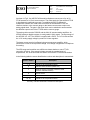
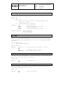
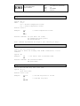
Fig 3: Block diagram of the power supply
All required voltages are generated on the CPU board. The main power supply for
the board is a standard FIERA 24V Kniel power supply mounted on the power supply
of the Detector Head. All other voltages are derived from this voltage using Deutronic
DC/DC converters.
Backplane
+24V
from
FIERA
power
supply
+5V
RESET
ESO
VLT Instrumentation
Pulpo 2 Manual
Doc.
Issue
Date
Page
VLT-TRE-ESO-13630-3490
1.0
07/12/2004
13 of 76
The maximum currents can be seen in the table below.
Voltage
max.Current
Used on :
+5V
2A
CPU Board +peripheral board
+3.3V
2A
CPU Board +peripheral board
+12V
1.6A
CPU Board +peripheral board
+15V
100mA
peripheral board
-15V
100mA
peripheral board + Display
Each voltage has auto resetting SMD fuses. Standard bypassing plus additional PI
filters are used to smoothen the supply voltages. A voltage supervisor, MAX 814, on
the 5V supply is used to generate a reset on power-up and in case of a power
failure.The MAX814 also provides the option of a manual reset via a button.The
Peripheral board is reset via the RSTDRV signal on the ISA bus and generated by
the 486Core.
The display requires an adjustable contrast voltage (from -9 to -12V). Due to the low
current (<4mA) it can be derived from the -15V by means of a simple voltage divider.
The +12V is used to provide power to the opto I/O's on the CPU board and the
peripheral board. On the CPU board it supplies the power to the optocouplers for the
serial ports and on the peripheral board it provides power to the shutter interface and
the user I/O lines.
A 3V lithium battery is used to keep the RTC (real time clock) running in case of a
power failure.
Note: The battery only serves as a backup source for the RTC, when Pulpo-2 is off.
All configuration data (set points, heater assignment, etc.) is stored in nonvolatile FLASH memory, and will be kept even if the battery fails.
ESO
4.3
VLT Instrumentation
Pulpo 2 Manual
Doc.
Issue
Date
Page
VLT-TRE-ESO-13630-3490
1.0
07/12/2004
14 of 76
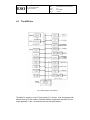
The 486Core
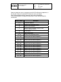
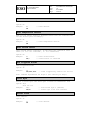
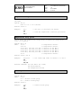
Fig. 4: Block diagram of the 486Core
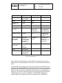
The 486Core module is a tiny PC Card module (75 x 54 mm). It can be equipped with
different sizes of FLASH memory, RAM and different configuration depending on the
target application. Table 1 summarises the most important features.
ESO
Doc.
Issue
Date
Page
VLT Instrumentation
Pulpo 2 Manual
Feature
Description
CPU Board
Processor
486 running at 33,
66, or 100Mhz
486 at 66Mhz
DRAM
8-32 MB
32MB
Program NOR
FLASH
1-8MB
4MB
NAND Flash Disk
1-136MB
16MB
LCD Graphics
controller
VLT-TRE-ESO-13630-3490
1.0
07/12/2004
15 of 76
Remarks
Parallel port device
driver or raw
control of the
parallel port lines
Might be used for
LCD. Alternatively
the parallel port or
GPIO can be used.
PCMCIA controller
Available
No
Control lines can
be used for other
purposes
PC/AT systemlogic
and essential
peripherals
Floppy Disk
controller, Parallel
port, 32 GPIO's,
IDE, Keyboard
controller
Parallel port,
GPIO's.
Either keyboard
controller or
GPIO's will be used
for keyboard
Power
consumption
dual supply
MTBF
100.000 hours
Network interface
Ethernet 10BaseT
with transformer
and EMI Filter
3.3V/5V
30mW/Mhz
Table 1: 486 Core features
About 300 KB of the NOR-FLASH is used for BIOS, the remaining part is used for
disk emulation. Flash ROM guarantees a minimum of 1,000,000 write operations per
sector.
For applications requiring large non-volatile on-board storage, the 486CORE can be
assembled with additional NAND Flash. NAND Flash is a block device optimized for
block read and write operations rather than random access. It is used to emulate FFS
(Flash File System, any piece of software that allows flash to be used similarly to a
disk drive). It is seen by the operating system as a regular hard disk. NAND Flash is
available with size of 16, 32, 64 or 128 Mbytes. The 486CORE is designed for
upward NAND Flash compatibility with future and larger devices. NAND Flash
ESO
VLT Instrumentation
Pulpo 2 Manual
Doc.
Issue
Date
Page
VLT-TRE-ESO-13630-3490
1.0
07/12/2004
16 of 76
guarantees a minimum of 1,000,000 block write operations and 10-year data
retention.
Most of the control lines on the 486Core are multiplexed between different functions.
There is always a trade-off between them e.g. enabling the keyboard controller limits
the memory usage to 16MB.
Three GPIO's (General Purpose I/O) would be needed for the input buttons and one
for the control of display illumination.
The 486Core offers 6 GPIO's which are not multiplexed, thus ensuring that the full
functionality will be maintained. More I/O lines can be made available by disabling
the PCMCIA slot. There are no plans to use the PCMCIA interface for the CPU
board.
ESO
VLT Instrumentation
Pulpo 2 Manual
Doc.
Issue
Date
Page
VLT-TRE-ESO-13630-3490
1.0
07/12/2004
17 of 76
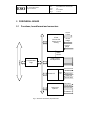
5 PERIPHERAL BOARD
5.1
Functions, board format and connectors
1mA to
PT100
PT100,
Vacuum and
heater current
sensing
PT100
voltage
Vacuum
gauge
ISA-Bus
heater
current
Programmable
Logic
Heater Control
and Supervision
Open Command
Shutter I/F
OptoI/O
Shutter Open
Shutter Close
Shutter Fail
Remote Status
Temp-Alarm
Vacuum Alarm
Relays and
Opto I/O
Vacuum Power
User I/O
Fig. 5: Overview of PULPO-II peripheral board
ESO
VLT Instrumentation
Pulpo 2 Manual
Doc.
Issue
Date
Page
VLT-TRE-ESO-13630-3490
1.0
07/12/2004
18 of 76
The Pulpo-2 peripheral board offers the following functionalities:
•
•
•
•
•
•
•
•
Possibility to connect up to 32 sensors:
- one vacuum sensor (type Balzers or Edwards)
- one reference sensor (connected to an internal, 100 Ω precision calibration
resistor)
- one heater current sensor (to show the current used by the heaters)
- up to 29 PT100 temperature sensors
Heater control of up to 8 heaters (the overall current cannot exceed 3A)
Safety options for heater control: Software triggered watchdog (max. 1 sec.
trigger interval), overcurrent sensing in hardware, current sensing in software
opto-coupled shutter interface with 1ms resolution, 61ns accuracy, hardware
controlled exposure time
2 relays for alarm signaling (vacuum and temperature)
1 relay to switch vacuum power supply
2 additional spare optocoupled outputs and 2 inputs (on the shutter
connector)
current output for LED driving
The board has the standard 3U-Eurocard format (160 x 100 mm). A 96-pin DIN
41612 VG-connector is used for the connection to the CPU-module and for supplying
power to the peripheral board.
The power supply is +24VDC for the heaters (@ 3A), +/-15VDC (@ 150 mA) for the
analog sensing, +5VDC (@ 350 mA) for the digital electronics, +12V (@100mA) for
optocouplers.
The ground for +24V is connected to analog ground directly at the VG-connector.
The analog ground will be connected to digital ground at the ADC.
Flat ribbon cables connect PT100s, heaters, etc. internally to the PULPO housing.
The Samtec "FFSD" series with a pitch of 1.27 mm are used. Two pins per connector
are employed for the heater signals to distribute the current.
ESO
5.2
Doc.
Issue
Date
Page
VLT Instrumentation
Pulpo 2 Manual
VLT-TRE-ESO-13630-3490
1.0
07/12/2004
19 of 76
Bus interface
The bus interface is an ISA (Industry Standard Architecture) interface exclusively
using 16-bit I/O-cycles. The following bus signals are used to decode valid accesses
from the CPU:
Signal
Input/Output
Full Signal Name
Usage
AEN
Input
Address Enable
inactive for valid access
BALE
Input
Buffered Address Latch
Enable
Active at start of cycle for valid
access
Clk
Input
Clock
14.385 MHz System Clock
SA0..15
Input
System Address
16-bit address
SD0..15
Bidirectional
System Data
16-bit data
/IOR
Input
I/O Read
Read cycle
/IOW
Input
I/O Write
Write cycle
I/OCS16
Tristate Output
I/O chip select 16
Indicate 16bit I/O cycle possible
/0WS
Tristate Output
0 wait state
Indicate zero wait state cycle
I/OCHRDY
Tristate Output
I/O Channel Ready
Indicate cycle completed
RESETDRV
Input
Reset
Power up or system reset
IRQ5, IRQ13
Tristate Output
Interrupt Request
IRQ5 used for optional interrupt
signalling
The signal assignment on the backplane follows the one that is specified for the
Pulpo-2 CPU-board.
Zero wait-state, 16-bit I/O cycles are implemented on the ISA-interface. No other
accesses are supported. The registers are normally polled, but interrupts are
available for certain bits. IRQ5 (normally used) and IRQ13 (supplementary) are
connected to the PLD (Programmable Logic Device). The interrupt is generated,
when a certain condition is encountered (e.g. watchdog not triggered) and the
corresponding interrupt enable bit is set (watchdog interrupt enable). The interrupt is
released, when the bit is polled (i.e. read cycle to watchdog status bit).
The board identification number can be set using two solder jumpers, i.e. there are
four possible identification numbers (the identification number 00 should not be used,
since this combination results in I/O-port addresses of 0-31, which are already in use
by the CPU).
The system clock is 14.385 Mhz. The timing of the shutter is derived from a local
oscillator and is therefore independent of the system clock.
ESO
VLT Instrumentation
Pulpo 2 Manual
Doc.
Issue
Date
Page
VLT-TRE-ESO-13630-3490
1.0
07/12/2004
20 of 76
There will not be any termination or “quiet state biasing” of signals. This has to be
done on the CPU board (e.g. pulling AEN low or pulling /0WS high).
ESO
5.3
Doc.
Issue
Date
Page
VLT Instrumentation
Pulpo 2 Manual
VLT-TRE-ESO-13630-3490
1.0
07/12/2004
21 of 76
Sensors
ADG707
1 mA
current
Mux,
sense
1 of 8
PT100
source
ϑ
Gn
ADG707
Data
PLD
16-bit
ADC
Instr.
Amplif.
Mux,
sense
1 of 8
PT100
Control
Gain
PT100 select
Supply and
sense
16 PT100,
4 x ADG707
ϑ
Supply and
sense
8 PT100,
2 x ADG707
Supply and
sense
reference
resistor,
sense
vacuum
sensor and
heater
current,
5 PT100
sensors
2 x ADG707
ϑ
reference
resistor
Vacuum
Heater current
Fig.6: Sensor Interfacing
ESO
VLT Instrumentation
Pulpo 2 Manual
Doc.
Issue
Date
Page
VLT-TRE-ESO-13630-3490
1.0
07/12/2004
22 of 76
As shown in Fig.6, four ADG707-differential multiplexers connect one of up to 29
PT100 sensors to a 0,5 mA current source. The other terminal of the selected PT100
is simultaneously switched to ground. Four additional ADG707-differential
multiplexers connect one of the sense conductors of the selected PT100, the
reference resistor or the vacuum gauge or the heater current sense output to an
analog signal chain. The gain in the signal chain can be switched to accommodate
the different output levels of the PT100s and the vacuum gauge.
The analog chain uses the PGA205 and the INA118 instrumentation amplifiers. An
AD7663 analog-to-digital converter is used (parallel 16-bit output). The input range of
the AD7663 is 0..10V. The AD7663 is supplied with +5VDC. The +5V is derived from
the +15V analog supply voltage by means of a linear regulator.
The heater current sensing is effected using a current sense amplifier, which
converts the current to an equivalent voltage. This voltage is supplied to a multiplexer
for sensing.
The ADC range and resolution are sufficient to detect whether or not a PT100connection is broken. If the sensed voltage exceeds the nominal range of
temperatures, one of the wires that are used to connect the PT100 must be broken.
In the following table the sensor identification number and description is summarized:
Sensor number
1...5
Description
internal PT100 Temperature sensor
6
external PT100 connector (FIERA box)
7
reference sensor (connected to internal, 100 Ω
precision calibration resistor)
8
vacuum sensor
9
heater current sensor
10...32
internal PT100 Temperature sensor
Summary of sensor identification numbers and description
ESO
Doc.
Issue
Date
Page
VLT Instrumentation
Pulpo 2 Manual
VLT-TRE-ESO-13630-3490
1.0
07/12/2004
23 of 76
External multiplexers can be connected to the ADG707-differential multiplexers, in
this way the number of connected PT100 sensors can be increased.
So far, this possibility has been used only in the case of OmegaCam.
In the following table the OmegaCam identification number and description is
summarized:
Sensor number
1...4
Description
to external multiplexers
5
internal PT100 Temperature sensor
6
external PT100 connector
7
reference sensor (connected to internal, 100 Ω
precision calibration resistor)
8
vacuum sensor
9
heater current sensor
10...32
internal PT100 Temperature sensor
111...118
external PT100 via external multiplexer 1
121...128
external PT100 via external multiplexer 1
131...138
external PT100 via external multiplexer 1
211...218
external PT100 via external multiplexer 2
221...228
external PT100 via external multiplexer 2
231...238
external PT100 via external multiplexer 2
311...318
external PT100 via external multiplexer 3
321...328
external PT100 via external multiplexer 3
331...338
external PT100 via external multiplexer 3
411...418
external PT100 via external multiplexer 4
421...428
external PT100 via external multiplexer 4
431...438
external PT100 via external multiplexer 4
Summary of sensor identification numbers and description in the OmegaCam
ESO
5.4
Doc.
Issue
Date
Page
VLT Instrumentation
Pulpo 2 Manual
VLT-TRE-ESO-13630-3490
1.0
07/12/2004
24 of 76
Heater control
PLD
+24VDC supply
softwaretriggered
watchdog
(1 sec.)
heater
control
register
MAX 471
current
sense
amplifier
MOSFET
switches
heater control 0..7
DAC
heater
status
register
current
sense input
+
-
overcurrent
alarm
overcurrent
trip point
Fig. 7: heater control
With the Pulpo-2 Peripheral board it is possible to connect up to 8 heaters. These
heaters are driven with 24V in PWM-Mode. The overall current for all heaters must
not exceed 3A. A MOSFET switch is connected in series to each heater and switches
the current (320 mA) through the heater.
The heaters can be activated individually. The total heater current is sensed and the
overcurrent trip point is set for the total heater current.
The overcurrent trip point can be set by software (via the second channel of the DAC
for the bias LED) or alternatively using a potentiometer. A 2-channel 12-bit serial
DAC (MAX532) is used for the circuit to drive a bias LED with a constant current.
Safety mechanisms to avoid overcurrent damaging the CCD:
• Software-triggered watchdog (1 second interval for triggering) in the PLD
• Current Sensing and possibility to read-back current value by software (see
section 4.2)
ESO
•
VLT Instrumentation
Pulpo 2 Manual
Doc.
Issue
Date
Page
VLT-TRE-ESO-13630-3490
1.0
07/12/2004
25 of 76
Comparison of heater current with trip point. This is implemented in hardware
(see Fig. 7), whereby the trip point can be fixed (potentiometer) or set by
software (DAC). The selection between hardware and software settings is
made by means of solder jumper on the peripheral board.
ESO
5.5
Doc.
Issue
Date
Page
VLT Instrumentation
Pulpo 2 Manual
VLT-TRE-ESO-13630-3490
1.0
07/12/2004
26 of 76
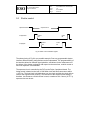
Shutter control
/OpenCommand
/FullyClosed
/FullyOpen
exposure time
event
#1
event
#4
event
#2
event
#3
Fig. 8: shutter control and status signals
The shutter timing of Fig.8 is one possible example. Due to a programmable shutter
interface different shutter configurations can be implemented. The programmability of
the interface allows for different signal polarities, and allows for the measurement of
the delays of the shutter mechanics with respect to the exact time, at which a start or
end of an exposure is commanded.
The exposure time is controlled by the PLD on the Pulpo-2 peripheral board. The
timing control is based on the local 16.000 MHz clock and hence accurate to within
+/- 62.5 ns. The local clock is divided down to a 1ms-clock and this slow clock is then
used for the exposure time counting. The resolution of the exposure time setting is
therefore 1ms. Because a 24-bit counter is used, a maximum of 4.6 hours (16.777 s)
exposure time can be set.
ESO
Doc.
Issue
Date
Page
VLT Instrumentation
Pulpo 2 Manual
VLT-TRE-ESO-13630-3490
1.0
07/12/2004
27 of 76
The shutter control on the Pulpo-2 peripheral board uses the following shutter
signals:
Signal
Input/Output
Function
/OpenCommand
Output
shutter opens when signal is active (active low or
high programmable)
/FullyClosed
Input
pulses inactive, when shutter leaves and enters
fully closed status (acc. to configuration of Fig. 8)
/FullyOpen
Input
pulses inactive, when shutter leaves and enters
fully open status (acc. to configuration of Fig. 8)
ShutterFail
Input
shutter failed
RemoteStatus
Input
shutter dependent
All shutter I/F-signals are opto-isolated to avoid ground loops.
The exposure command (/OpenCommand = 0) is issued to the shutter when the
StartExposure-bit in the shutter control register is set. A counter is initialized with the
combined value of the shutter exposure time low word and high word registers and
downcounting is started. Moreover, the counters for the Event1- and Event2-delays
are reset and start incrementing. The event1 counter is stopped, when event1
occurs. Event1 is defined as a transition of the /FullyClosed-bit. Whether the leading
or trailing edge of the /FullyClosed-bit is taken as event1, is defined by the
Event1ActiveEdge-bit in the shutter status/control register (see chapter “Software
Interface”). The event2-delay is similarly counted (see Fig.8).
The exposure is finished (/OpenCommand = 1) when the shutter control register
count reaches zero. Event3 and event4-counters are reset and start incrementing at
this point. The counters are stopped on the occurrence of event3 and event4,
respectively. The event-counters comprise 16-bits, which allows for delays up to
65 seconds.
5.6
Other functions
Other functions on the Pulpo 2 board are four alarm outputs (two temperature alarms
and two vacuum alarms) as well as two user-defined outputs and inputs. The alarm
signals are used to close two normally-open relays. The user defined outputs and
inputs are opto-isolated.
An additional relay can be used to switch the power of the vacuum sensor.
The Peripheral board also controls two LEDs on the front panel. One LED lights up
when one heater is on and the other when the shutter is open.
ESO
5.7
Doc.
Issue
Date
Page
VLT Instrumentation
Pulpo 2 Manual
VLT-TRE-ESO-13630-3490
1.0
07/12/2004
28 of 76
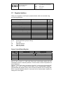
Register interface
There are 14 registers on the Pulpo-2 peripheral board, which are accessed using
the following addresses:
Register
Binary address, SA15..0
Sensor Control/Status Register
Sensor Data Register
Heater Control Register
Heater Supervision Register
Serial DAC Control/Status Reg
Serial DAC Data Register
Shutter Control/Status Register
Shutter Exposure Time High Word Register
Shutter Exposure Time Low Word Register
Event1 counter
Event2 counter
Event3 counter
Event4 counter
Misc I/O Register
ID1 ID0 X X X X X X X X X X 1 0 0 0
ID1 ID0 X X X X X X X X X X 0 1 0 1
ID1 ID0 X X X X X X X X X X 1 1 0 1
ID1 ID0 X X X X X X X X X X 1 0 0 1
ID1 ID0 X X X X X X X X X X 1 1 0 0
ID1 ID0 X X X X X X X X X X 1 0 1 1
ID1 ID0 X X X X X X X X X X 0 1 1 0
ID1 ID0 X X X X X X X X X X 0 1 1 1
ID1 ID0 X X X X X X X X X X 0 0 0 0
ID1 ID0 X X X X X X X X X X 0 0 0 1
ID1 ID0 X X X X X X X X X X 0 0 1 0
ID1 ID0 X X X X X X X X X X 0 0 1 1
ID1 ID0 X X X X X X X X X X 0 1 0 0
ID1 ID0 X X X X X X X X X X 1 0 1 0
ID1..0:
X:
r/w:
ro:
wo:
Access
type
r/w
ro
wo
r/w
wo
r/w
r/w
r/w
r/w
ro
ro
ro
ro
r/w
board identification (jumper setting)
don´t care
read/write-access
read only access
write only access
Sensor Control/Status Register
bit
15..8
7
6
5
4..0
write access
read access
not used
ADC start of conversion
PGA gain control
enable sensor/mux
sensor channel
ADC Busy
Bits 15..8 are not used, i.e. a read cycle of the sensor control/status register will yield
meaningless results in these bit positions. The bits written to these bit positions will
not be registered.
Writing a 1 to bit 7 will start a conversion of the ADC. A read cycle will yield the ADC
status in bit 7. Bit 6 is used to set the gain of the instrumentation amplifier /
programmable gain amplifier (PGA). One of 32 sensor channels can be selected with
bits 4..0 and the selected channel is connected to the instrumentation amplifier by
setting bit 5 of the register.
ESO
VLT Instrumentation
Pulpo 2 Manual
Doc.
Issue
Date
Page
VLT-TRE-ESO-13630-3490
1.0
07/12/2004
29 of 76
The channel assignment of the sensors is as follows:
sensor channel (bits 4..0 of sensor
control/status register)
1...5
6
7
8
9
10...32
sensor
PT100 in cryostat
PT100 in FIERA
100 Ω reference resistor
vacuum sensor
heater current
optional PT100 sensors
Sensor Data Register
bit
15...0
write access
no result
read access
last converted sensor value
Heater Control Register
bit
15...9
8
7
6
5
4
3
2
1
0
write access
read access
unused
heater enable
heater select 7
heater select 6
heater select 5
heater select 4
heater select 3
heater select 2
heater select 1
heater select 0
not used
not used
not used
not used
not used
not used
not used
not used
not used
Every heater can be individually enabled or disabled independent of all other heaters.
A heater is switched on, if the heater select bit for the specific heater is set and the
heater enable bit is set as well.
Heater Supervision Register
bit
15...5
4
3
2
1
0
write access
read access
not used
watchdog interrupt enable
overcurrent interrupt enable
watchdog trigger
watchdog reset
overcurrent reset
not used
not used
not used
watchdog status
overcurrent status
ESO
VLT Instrumentation
Pulpo 2 Manual
Doc.
Issue
Date
Page
VLT-TRE-ESO-13630-3490
1.0
07/12/2004
30 of 76
The overcurrent status bit is set as soon as the overcurrent condition is encountered.
The bit can only be reset by a global board reset (RESETDRV-Line of the ISA-Bus)
or writing a 1 to the overcurrent reset bit.
The same applies for the watchdog status bit. This bit is set, when the watchdog
trigger bit is not written to in regular intervals of <1 second. Once set, the bit can only
be reset by writing a 1 to the watchdog reset bit.
Both status bits can be used to generate interrupts.
Serial DAC Control Register
bit
15...2
1
0
write access
read access
not used
Chip Select DAC
Load DAC
not used
not used
The Chip Select DAC and the Load DAC bits connect to the CSDAC and LdDAC
inputs of the serial DAC.
Provided the jumper on the board is set to programmable overcurrent, the
overcurrent trip point can be set in steps of 0.73 mA within a range of 0 mA to 3 A,
i.e. one increment of the overcurrent trip point register (one DN, data number)
corresponds to 0.73 mA. The overall current cannot exceed.
The bias LED current is also determined by the programming of the serial DAC,
second channel.
Serial DAC Data Register
bit
15...1
0
write access
read access
not used
serial data in
serial data out
The SClk signal is automatically generated with the proper timing. For details
concerning the sequence of data bits, see data sheet MAX532.
ESO
VLT Instrumentation
Pulpo 2 Manual
Doc.
Issue
Date
Page
VLT-TRE-ESO-13630-3490
1.0
07/12/2004
31 of 76
Shutter Status/Control Register
bit
15
14
13
12
11
10
9
8
7
6
5
4
3
2
1
0
write access
read access
StartExposure
not used
AbortExposure
not used
PauseExposure
not used
EndofExposure Interrupt Enable
EndofExposure
DarkExposure
OpenCommandActHi
RemoteStatus Interrupt Enable
RemoteStatus Line
ShutterFail Interrupt Enable
ShutterFail Line
Event4 is a rising edge
Event4 counter overrun
Event3 is a rising edge
Event3 counter overrun
Event2 is a rising edge
Event2 counter overrun
Event1 is a rising edge
Event1 counter overrun
Event4 Interrupt Enable
Event4 encountered
Event3 Interrupt Enable
Event3 encountered
Event2 Interrupt Enable
Event2 encountered
Event1 Interrupt Enable
Event1 encountered
The status of the RemoteStatus and ShutterFail-signals is directly reflected in bits 9
and 8 of the shutter status register. The readable bits 0..7 are used to signal an
overrun of the event-counters and the occurrence of an event. Bit 12 signals that the
exposure time counter has counted down to zero. These bits 0..7 and 12 are reset,
when a shutter exposure is started.
In order to determine which interrupt source generated an interrupt, the status
register has to be read. If the interrupt is generated by a pulse on the RemoteStatus
or ShutterFail-line, the external hardware has to ensure that these lines are asserted
for a long enough period of time (interrupt latency + saftey margin), because
otherwise the interrupt source cannot be found out by software.
Bits 7-4 determine whether the respective event is considered to be triggered on a
falling (when bit=0) or a rising edge (bit=1). Each event can trigger an interrupt, if the
corresponding Event Interrupt Enable bit is set. The interrupt source can be
determined from the “Event encountered”-bits of the Shutter Status Register. The
“Event encountered” bits are reset, when the next exposure is started by setting the
StartExposure bit in the ShutterCtrlReg.
An exposure is started synchronous with an internal 1ms clock, immediately after the
StartExposure-bit is set. The exposure can be aborted. Aborting an exposure has the
same effect as if the shutter exposure time counter reaches zero, i.e. the
/OpenCommand-signal is reset. The only difference is that the EndofExposure-bit in
the Shutter Status/Control-Register is not set.
The setting of the PauseExposure-bit simply causes the shutter exposure time
counter to stop decrementing and keep the current value, until the PauseExposurebit is reset again.
The polarity of the OpenCommand-output can be set using the OpenCommandActHibit. If the DarkExposure-bit is set, the OpenCommand-line is kept in its inactive state
for the duration of the exposure, i.e. the shutter is not opened.
ESO
Doc.
Issue
Date
Page
VLT Instrumentation
Pulpo 2 Manual
VLT-TRE-ESO-13630-3490
1.0
07/12/2004
32 of 76
Shutter Exposure Time High Word Register
bit
15...8
7...0
write access
read access
not used
bits 23..16 of exposure time
The lowest 8 bits are used to set the highest byte of the shutter exposure time
counter.
Shutter Exposure Time Low Word Register
bit
15...0
write access
read access
bits 15..0 of exposure time
Whenever the StartExposure-bit in the shutter control/status register is set, the 24-bit
shutter exposure time counter is loaded with the composite contents of bits 7..0 from
the shutter exposure time high word register and bits 15..0 of the shutter exposure
time low word register. The /OpenCommand-signal is immediately asserted and the
shutter exposure time counter starts decrementing. The /OpenCommand is asserted
for the composite content of the exposure time registers + 1 in milliseconds.
Moreover, this register is available to test read/write accesses with 16 bit data (i.e. to
test whether the board is present, test whether all lines are operative, etc.).
Eventx Counter Register (x=1..4)
bit
15...12
11...0
write access
read access
not used
not used
event counter value
write access
MuxPower1
MuxPower0
MuxChannel[5..0]
read access
not used
not used
not used
Misc I/O-Register
bit
15
14
13...8
7...6
5
4
3
2
1
0
not used
LEDEnable
TemperatureAlarm
VacuumAlarm
VaccuumPower
OptoOut1
OptoOut0
not used
not used
not used
not used
OptoIn1
OptoIn0
Bit 5 is used to enable two LED outputs. One LED output can be connected to an
LED to signal that at least one of the heaters is powered on. The other LED output
signals that the shutter OpenCommand is asserted.
ESO
VLT Instrumentation
Pulpo 2 Manual
Doc.
Issue
Date
Page
VLT-TRE-ESO-13630-3490
1.0
07/12/2004
33 of 76
Bits 4 and 3 are used to switch a relay in case that an overtemperature or loss of
vacuum is detected. The relay can be used to trigger an alarm.
Bit 2 is available to switch the power supply to the vacuum sensor.
Bits 1 and 0 are user-defined inputs/outputs.
As an option bits 15 and 14 can be used to enable +15V/+5V and -15V to a
multiplexer in the detector head. Digital data bits 13..8 can be fed to the detector
head to select a multiplexer channel in the detector head.
ESO
Doc.
Issue
Date
Page
VLT Instrumentation
Pulpo 2 Manual
VLT-TRE-ESO-13630-3490
1.0
07/12/2004
34 of 76
6 SOFTWARE
The Pulpo-2 microprocessor is a 486CORE, with 16MB flash disk and 32MB DRAM.
The operating system is Linux EM i486.
The code - completely written in C - follows the VLTSW standards defined in [AD 01].
The code is archived within the CMM "pulpo2" module.
For detailed information about the software structure, compilation, debugging and
installation, refer to the README file in the "pulpo2" module.
6.1
Status bytes
Pulpo-2 has 34 status bytes which are used for maintaining information on
Pulpo-2 operation. They are accessible using the command SB,n where n can
be any number from 1 to 34.
STATUS BYTE 1
LEDEnab
BiasLedOn
HeaterOvercurrent
Watchdog
TunerActive
AlarmsGlobalEnabled
AlarmsGlobalTEnabled
Unused
STATUS BYTE 2
ShOpen
ExpPaused
ExpActive
ShutterNotConnected
StatusOpenAvailable
StatusCloseAvailable
StatusRemoteAvailable
ShutterError
STATUS BYTE 3
AlarmS1Enab
AlarmS2Enab
AlarmS3Enab
AlarmS4Enab
AlarmS5Enab
AlarmS6Enab
AlarmS7Enab
AlarmS8Enab
BIT
0
1
2
3
4
5
6
7
BIT
0
1
2
3
4
5
6
7
BIT
0
1
2
3
4
5
6
7
FUNCTION
Set if front panel status LEDs enabled
Set if Bias LED enabled
Set if Overcurrent
Set if Watchdog
Set if Tuner Active
Set if Global Alarm enabled
Set if Temperature Global Alarm enabled
Not Used
FUNCTION
Set if shutter open
Set if exposure paused by CCD controller (PE,1)
Set if exposure active
Set if no shutter detected at start-up shutter test
Set if OPEN status available at start-up shutter test
Set if CLOSE status available at start-up shutter test
Set if REMOTE status available at start-up shutter test
Set if Shutter error detected during start-up or normal
exp
FUNCTION
Set if Alarm enabled for Sensor 1
Set if Alarm enabled for Sensor 2
Set if Alarm enabled for Sensor 3
Set if Alarm enabled for Sensor 4
Set if Alarm enabled for Sensor 5
Set if Alarm enabled for Sensor 6
Set if Alarm enabled for Sensor 7
Set if Alarm enabled for Sensor 8
ESO
VLT Instrumentation
Pulpo 2 Manual
STATUS BYTE 4
AlarmS9Enab
AlarmS10Enab
AlarmS11Enab
AlarmS12Enab
AlarmS13Enab
AlarmS14Enab
AlarmS15Enab
AlarmS16Enab
STATUS BYTE 5
AlarmS17Enab
AlarmS18Enab
AlarmS19Enab
AlarmS20Enab
AlarmS21Enab
AlarmS22Enab
AlarmS23Enab
AlarmS24Enab
STATUS BYTE 6
AlarmS25Enab
AlarmS26Enab
AlarmS27Enab
AlarmS28Enab
AlarmS29Enab
AlarmS30Enab
AlarmS31Enab
AlarmS32Enab
BIT
0
1
2
3
4
5
6
7
BIT
0
1
2
3
4
5
6
7
BIT
0
1
2
3
4
5
6
7
STATUS BYTE 7
BIT
AlarmS111Enab
AlarmS112Enab
AlarmS113Enab
AlarmS114Enab
AlarmS115Enab
AlarmS116Enab
AlarmS117Enab
AlarmS118Enab
0
1
2
3
4
5
6
7
STATUS BYTE 8
BIT
AlarmS121Enab
AlarmS122Enab
AlarmS123Enab
AlarmS124Enab
AlarmS125Enab
AlarmS126Enab
AlarmS127Enab
AlarmS128Enab
0
1
2
3
4
5
6
7
Doc.
Issue
Date
Page
VLT-TRE-ESO-13630-3490
1.0
07/12/2004
35 of 76
FUNCTION
Set if Alarm enabled for Sensor 9
Set if Alarm enabled for Sensor 10
Set if Alarm enabled for Sensor 11
Set if Alarm enabled for Sensor 12
Set if Alarm enabled for Sensor 13
Set if Alarm enabled for Sensor 14
Set if Alarm enabled for Sensor 15
Set if Alarm enabled for Sensor 16
FUNCTION
Set if Alarm enabled for Sensor 17
Set if Alarm enabled for Sensor 18
Set if Alarm enabled for Sensor 19
Set if Alarm enabled for Sensor 20
Set if Alarm enabled for Sensor 21
Set if Alarm enabled for Sensor 22
Set if Alarm enabled for Sensor 23
Set if Alarm enabled for Sensor 24
FUNCTION
Set if Alarm enabled for Sensor 25
Set if Alarm enabled for Sensor 26
Set if Alarm enabled for Sensor 27
Set if Alarm enabled for Sensor 28
Set if Alarm enabled for Sensor 29
Set if Alarm enabled for Sensor 30
Set if Alarm enabled for Sensor 31
Set if Alarm enabled for Sensor 32
FUNCTION
Set if Alarm enabled for Sensor 111
Set if Alarm enabled for Sensor 112
Set if Alarm enabled for Sensor 113
Set if Alarm enabled for Sensor 114
Set if Alarm enabled for Sensor 115
Set if Alarm enabled for Sensor 116
Set if Alarm enabled for Sensor 117
Set if Alarm enabled for Sensor 118
FUNCTION
Set if Alarm enabled for Sensor 121
Set if Alarm enabled for Sensor 122
Set if Alarm enabled for Sensor 123
Set if Alarm enabled for Sensor 124
Set if Alarm enabled for Sensor 125
Set if Alarm enabled for Sensor 126
Set if Alarm enabled for Sensor 127
Set if Alarm enabled for Sensor 128
ESO
VLT Instrumentation
Pulpo 2 Manual
STATUS BYTE 9
BIT
AlarmS131Enab
AlarmS132Enab
AlarmS133Enab
AlarmS134Enab
AlarmS135Enab
AlarmS136Enab
AlarmS137Enab
AlarmS138Enab
0
1
2
3
4
5
6
7
STATUS BYTE 10
AlarmS211Enab
AlarmS212Enab
AlarmS213Enab
AlarmS214Enab
AlarmS215Enab
AlarmS216Enab
AlarmS217Enab
AlarmS218Enab
STATUS BYTE 11
AlarmS221Enab
AlarmS222Enab
AlarmS223Enab
AlarmS224Enab
AlarmS225Enab
AlarmS226Enab
AlarmS227Enab
AlarmS228Enab
STATUS BYTE 12
AlarmS231Enab
AlarmS232Enab
AlarmS233Enab
AlarmS234Enab
AlarmS235Enab
AlarmS236Enab
AlarmS237Enab
AlarmS238Enab
STATUS BYTE 13
AlarmS311Enab
AlarmS312Enab
AlarmS313Enab
AlarmS314Enab
AlarmS315Enab
AlarmS316Enab
AlarmS317Enab
AlarmS318Enab
BIT
0
1
2
3
4
5
6
7
BIT
0
1
2
3
4
5
6
7
BIT
0
1
2
3
4
5
6
7
BIT
0
1
2
3
4
5
6
7
Doc.
Issue
Date
Page
VLT-TRE-ESO-13630-3490
1.0
07/12/2004
36 of 76
FUNCTION
Set if Alarm enabled for Sensor 131
Set if Alarm enabled for Sensor 132
Set if Alarm enabled for Sensor 133
Set if Alarm enabled for Sensor 134
Set if Alarm enabled for Sensor 135
Set if Alarm enabled for Sensor 136
Set if Alarm enabled for Sensor 137
Set if Alarm enabled for Sensor 138
FUNCTION
Set if Alarm enabled for Sensor 211
Set if Alarm enabled for Sensor 212
Set if Alarm enabled for Sensor 213
Set if Alarm enabled for Sensor 214
Set if Alarm enabled for Sensor 215
Set if Alarm enabled for Sensor 216
Set if Alarm enabled for Sensor 217
Set if Alarm enabled for Sensor 218
FUNCTION
Set if Alarm enabled for Sensor 221
Set if Alarm enabled for Sensor 222
Set if Alarm enabled for Sensor 223
Set if Alarm enabled for Sensor 224
Set if Alarm enabled for Sensor 225
Set if Alarm enabled for Sensor 226
Set if Alarm enabled for Sensor 227
Set if Alarm enabled for Sensor 228
FUNCTION
Set if Alarm enabled for Sensor 231
Set if Alarm enabled for Sensor 232
Set if Alarm enabled for Sensor 233
Set if Alarm enabled for Sensor 234
Set if Alarm enabled for Sensor 235
Set if Alarm enabled for Sensor 236
Set if Alarm enabled for Sensor 237
Set if Alarm enabled for Sensor 238
FUNCTION
Set if Alarm enabled for Sensor 311
Set if Alarm enabled for Sensor 312
Set if Alarm enabled for Sensor 313
Set if Alarm enabled for Sensor 314
Set if Alarm enabled for Sensor 315
Set if Alarm enabled for Sensor 316
Set if Alarm enabled for Sensor 317
Set if Alarm enabled for Sensor 318
ESO
VLT Instrumentation
Pulpo 2 Manual
STATUS BYTE 14
AlarmS321Enab
AlarmS322Enab
AlarmS323Enab
AlarmS324Enab
AlarmS325Enab
AlarmS326Enab
AlarmS327Enab
AlarmS328Enab
STATUS BYTE 15
AlarmS331Enab
AlarmS332Enab
AlarmS333Enab
AlarmS334Enab
AlarmS335Enab
AlarmS336Enab
AlarmS337Enab
AlarmS338Enab
STATUS BYTE 16
AlarmS411Enab
AlarmS412Enab
AlarmS413Enab
AlarmS414Enab
AlarmS415Enab
AlarmS416Enab
AlarmS417Enab
AlarmS418Enab
STATUS BYTE 17
AlarmS421Enab
AlarmS422Enab
AlarmS423Enab
AlarmS424Enab
AlarmS425Enab
AlarmS426Enab
AlarmS427Enab
AlarmS428Enab
STATUS BYTE 18
AlarmS431Enab
AlarmS432Enab
AlarmS433Enab
AlarmS434Enab
AlarmS435Enab
AlarmS436Enab
AlarmS437Enab
AlarmS438Enab
BIT
0
1
2
3
4
5
6
7
BIT
0
1
2
3
4
5
6
7
BIT
0
1
2
3
4
5
6
7
BIT
0
1
2
3
4
5
6
7
BIT
0
1
2
3
4
5
6
7
Doc.
Issue
Date
Page
VLT-TRE-ESO-13630-3490
1.0
07/12/2004
37 of 76
FUNCTION
Set if Alarm enabled for Sensor 321
Set if Alarm enabled for Sensor 322
Set if Alarm enabled for Sensor 323
Set if Alarm enabled for Sensor 324
Set if Alarm enabled for Sensor 325
Set if Alarm enabled for Sensor 326
Set if Alarm enabled for Sensor 327
Set if Alarm enabled for Sensor 328
FUNCTION
Set if Alarm enabled for Sensor 331
Set if Alarm enabled for Sensor 332
Set if Alarm enabled for Sensor 333
Set if Alarm enabled for Sensor 334
Set if Alarm enabled for Sensor 335
Set if Alarm enabled for Sensor 336
Set if Alarm enabled for Sensor 337
Set if Alarm enabled for Sensor 338
FUNCTION
Set if Alarm enabled for Sensor 411
Set if Alarm enabled for Sensor 412
Set if Alarm enabled for Sensor 413
Set if Alarm enabled for Sensor 414
Set if Alarm enabled for Sensor 415
Set if Alarm enabled for Sensor 416
Set if Alarm enabled for Sensor 417
Set if Alarm enabled for Sensor 418
FUNCTION
Set if Alarm enabled for Sensor 421
Set if Alarm enabled for Sensor 422
Set if Alarm enabled for Sensor 423
Set if Alarm enabled for Sensor 424
Set if Alarm enabled for Sensor 425
Set if Alarm enabled for Sensor 426
Set if Alarm enabled for Sensor 427
Set if Alarm enabled for Sensor 428
FUNCTION
Set if Alarm enabled for Sensor 431
Set if Alarm enabled for Sensor 432
Set if Alarm enabled for Sensor 433
Set if Alarm enabled for Sensor 434
Set if Alarm enabled for Sensor 435
Set if Alarm enabled for Sensor 436
Set if Alarm enabled for Sensor 437
Set if Alarm enabled for Sensor 438
ESO
VLT Instrumentation
Pulpo 2 Manual
STATUS BYTE 19
AlarmS1Trigger
AlarmS2Trigger
AlarmS3Trigger
AlarmS4Trigger
AlarmS5Trigger
AlarmS6Trigger
AlarmS7Trigger
AlarmS8Trigger
STATUS BYTE 20
AlarmS9Trigger
AlarmS10Trigger
AlarmS11Trigger
AlarmS12Trigger
AlarmS13Trigger
AlarmS14Trigger
AlarmS15Trigger
AlarmS16Trigger
STATUS BYTE 21
AlarmS17Trigger
AlarmS18Trigger
AlarmS19Trigger
AlarmS20Trigger
AlarmS21Trigger
AlarmS22Trigger
AlarmS23Trigger
AlarmS24Trigger
STATUS BYTE 22
AlarmS25Trigger
AlarmS26Trigger
AlarmS27Trigger
AlarmS28Trigger
AlarmS29Trigger
AlarmS30Trigger
AlarmS31Trigger
AlarmS32Trigger
BIT
0
1
2
3
4
5
6
7
BIT
0
1
2
3
4
5
6
7
BIT
0
1
2
3
4
5
6
7
BIT
0
1
2
3
4
5
6
7
STATUS BYTE 23
BIT
AlarmS111Trigger
AlarmS112Trigger
AlarmS113Trigger
AlarmS114Trigger
AlarmS115Trigger
AlarmS116Trigger
AlarmS117Trigger
AlarmS118Trigger
0
1
2
3
4
5
6
7
Doc.
Issue
Date
Page
VLT-TRE-ESO-13630-3490
1.0
07/12/2004
38 of 76
FUNCTION
Set if Alarm triggered for Sensor 1
Set if Alarm triggered for Sensor 2
Set if Alarm triggered for Sensor 3
Set if Alarm triggered for Sensor 4
Set if Alarm triggered for Sensor 5
Set if Alarm triggered for Sensor 6
Set if Alarm triggered for Sensor 7
Set if Alarm triggered for Sensor 8
FUNCTION
Set if Alarm triggered for Sensor 9
Set if Alarm triggered for Sensor 10
Set if Alarm triggered for Sensor 11
Set if Alarm triggered for Sensor 12
Set if Alarm triggered for Sensor 13
Set if Alarm triggered for Sensor 14
Set if Alarm triggered for Sensor 15
Set if Alarm triggered for Sensor 16
FUNCTION
Set if Alarm triggered for Sensor 17
Set if Alarm triggered for Sensor 18
Set if Alarm triggered for Sensor 19
Set if Alarm triggered for Sensor 20
Set if Alarm triggered for Sensor 21
Set if Alarm triggered for Sensor 22
Set if Alarm triggered for Sensor 23
Set if Alarm triggered for Sensor 24
FUNCTION
Set if Alarm triggered for Sensor 25
Set if Alarm triggered for Sensor 26
Set if Alarm triggered for Sensor 27
Set if Alarm triggered for Sensor 28
Set if Alarm triggered for Sensor 29
Set if Alarm triggered for Sensor 30
Set if Alarm triggered for Sensor 31
Set if Alarm triggered for Sensor 32
FUNCTION
Set if Alarm triggered for Sensor 111
Set if Alarm triggered for Sensor 112
Set if Alarm triggered for Sensor 113
Set if Alarm triggered for Sensor 114
Set if Alarm triggered for Sensor 115
Set if Alarm triggered for Sensor 116
Set if Alarm triggered for Sensor 117
Set if Alarm triggered for Sensor 118
ESO
VLT Instrumentation
Pulpo 2 Manual
STATUS BYTE 24
BIT
AlarmS121Trigger
AlarmS122Trigger
AlarmS123Trigger
AlarmS124Trigger
AlarmS125Trigger
AlarmS126Trigger
AlarmS127Trigger
AlarmS128Trigger
0
1
2
3
4
5
6
7
STATUS BYTE 25
BIT
AlarmS131Trigger
AlarmS132Trigger
AlarmS133Trigger
AlarmS134Trigger
AlarmS135Trigger
AlarmS136Trigger
AlarmS137Trigger
AlarmS138Trigger
0
1
2
3
4
5
6
7
STATUS BYTE 26
BIT
AlarmS211Trigger
AlarmS212Trigger
AlarmS213Trigger
AlarmS214Trigger
AlarmS215Trigger
AlarmS216Trigger
AlarmS217Trigger
AlarmS218Trigger
0
1
2
3
4
5
6
7
STATUS BYTE 27
BIT
AlarmS221Trigger
AlarmS222Trigger
AlarmS223Trigger
AlarmS224Trigger
AlarmS225Trigger
AlarmS226Trigger
AlarmS227Trigger
AlarmS228Trigger
0
1
2
3
4
5
6
7
STATUS BYTE 28
BIT
AlarmS231Trigger
AlarmS232Trigger
AlarmS233Trigger
AlarmS234Trigger
AlarmS235Trigger
AlarmS236Trigger
AlarmS237Trigger
AlarmS238Trigger
0
1
2
3
4
5
6
7
Doc.
Issue
Date
Page
VLT-TRE-ESO-13630-3490
1.0
07/12/2004
39 of 76
FUNCTION
Set if Alarm triggered for Sensor 121
Set if Alarm triggered for Sensor 122
Set if Alarm triggered for Sensor 123
Set if Alarm triggered for Sensor 124
Set if Alarm triggered for Sensor 125
Set if Alarm triggered for Sensor 126
Set if Alarm triggered for Sensor 127
Set if Alarm triggered for Sensor 128
FUNCTION
Set if Alarm triggered for Sensor 131
Set if Alarm triggered for Sensor 132
Set if Alarm triggered for Sensor 133
Set if Alarm triggered for Sensor 134
Set if Alarm triggered for Sensor 135
Set if Alarm triggered for Sensor 136
Set if Alarm triggered for Sensor 137
Set if Alarm triggered for Sensor 138
FUNCTION
Set if Alarm triggered for Sensor 211
Set if Alarm triggered for Sensor 212
Set if Alarm triggered for Sensor 213
Set if Alarm triggered for Sensor 214
Set if Alarm triggered for Sensor 215
Set if Alarm triggered for Sensor 216
Set if Alarm triggered for Sensor 217
Set if Alarm triggered for Sensor 218
FUNCTION
Set if Alarm triggered for Sensor 221
Set if Alarm triggered for Sensor 222
Set if Alarm triggered for Sensor 223
Set if Alarm triggered for Sensor 224
Set if Alarm triggered for Sensor 225
Set if Alarm triggered for Sensor 226
Set if Alarm triggered for Sensor 227
Set if Alarm triggered for Sensor 228
FUNCTION
Set if Alarm triggered for Sensor 231
Set if Alarm triggered for Sensor 232
Set if Alarm triggered for Sensor 233
Set if Alarm triggered for Sensor 234
Set if Alarm triggered for Sensor 235
Set if Alarm triggered for Sensor 236
Set if Alarm triggered for Sensor 237
Set if Alarm triggered for Sensor 238
ESO
VLT Instrumentation
Pulpo 2 Manual
STATUS BYTE 29
BIT
AlarmS311Trigger
AlarmS312Trigger
AlarmS313Trigger
AlarmS314Trigger
AlarmS315Trigger
AlarmS316Trigger
AlarmS317Trigger
AlarmS318Trigger
0
1
2
3
4
5
6
7
STATUS BYTE 30
BIT
AlarmS321Trigger
AlarmS322Trigger
AlarmS323Trigger
AlarmS324Trigger
AlarmS325Trigger
AlarmS326Trigger
AlarmS327Trigger
AlarmS328Trigger
0
1
2
3
4
5
6
7
STATUS BYTE 31
BIT
AlarmS331Trigger
AlarmS332Trigger
AlarmS333Trigger
AlarmS334Trigger
AlarmS335Trigger
AlarmS336Trigger
AlarmS337Trigger
AlarmS338Trigger
0
1
2
3
4
5
6
7
STATUS BYTE 32
BIT
AlarmS411Trigger
AlarmS412Trigger
AlarmS413Trigger
AlarmS414Trigger
AlarmS415Trigger
AlarmS416Trigger
AlarmS417Trigger
AlarmS418Trigger
0
1
2
3
4
5
6
7
STATUS BYTE 33
BIT
AlarmS421Trigger
AlarmS422Trigger
AlarmS423Trigger
AlarmS424Trigger
AlarmS425Trigger
AlarmS426Trigger
AlarmS427Trigger
AlarmS428Trigger
0
1
2
3
4
5
6
7
Doc.
Issue
Date
Page
VLT-TRE-ESO-13630-3490
1.0
07/12/2004
40 of 76
FUNCTION
Set if Alarm triggered for Sensor 311
Set if Alarm triggered for Sensor 312
Set if Alarm triggered for Sensor 313
Set if Alarm triggered for Sensor 314
Set if Alarm triggered for Sensor 315
Set if Alarm triggered for Sensor 316
Set if Alarm triggered for Sensor 317
Set if Alarm triggered for Sensor 318
FUNCTION
Set if Alarm triggered for Sensor 321
Set if Alarm triggered for Sensor 322
Set if Alarm triggered for Sensor 323
Set if Alarm triggered for Sensor 324
Set if Alarm triggered for Sensor 325
Set if Alarm triggered for Sensor 326
Set if Alarm triggered for Sensor 327
Set if Alarm triggered for Sensor 328
FUNCTION
Set if Alarm triggered for Sensor 331
Set if Alarm triggered for Sensor 332
Set if Alarm triggered for Sensor 333
Set if Alarm triggered for Sensor 334
Set if Alarm triggered for Sensor 335
Set if Alarm triggered for Sensor 336
Set if Alarm triggered for Sensor 337
Set if Alarm triggered for Sensor 338
FUNCTION
Set if Alarm triggered for Sensor 411
Set if Alarm triggered for Sensor 412
Set if Alarm triggered for Sensor 413
Set if Alarm triggered for Sensor 414
Set if Alarm triggered for Sensor 415
Set if Alarm triggered for Sensor 416
Set if Alarm triggered for Sensor 417
Set if Alarm triggered for Sensor 418
FUNCTION
Set if Alarm triggered for Sensor 421
Set if Alarm triggered for Sensor 422
Set if Alarm triggered for Sensor 423
Set if Alarm triggered for Sensor 424
Set if Alarm triggered for Sensor 425
Set if Alarm triggered for Sensor 426
Set if Alarm triggered for Sensor 427
Set if Alarm triggered for Sensor 428
ESO
VLT Instrumentation
Pulpo 2 Manual
STATUS BYTE 34
BIT
AlarmS431Trigger
AlarmS432Trigger
AlarmS433Trigger
AlarmS434Trigger
AlarmS435Trigger
AlarmS436Trigger
AlarmS437Trigger
AlarmS438Trigger
0
1
2
3
4
5
6
7
Doc.
Issue
Date
Page
VLT-TRE-ESO-13630-3490
1.0
07/12/2004
41 of 76
FUNCTION
Set if Alarm triggered for Sensor 431
Set if Alarm triggered for Sensor 432
Set if Alarm triggered for Sensor 433
Set if Alarm triggered for Sensor 434
Set if Alarm triggered for Sensor 435
Set if Alarm triggered for Sensor 436
Set if Alarm triggered for Sensor 437
Set if Alarm triggered for Sensor 438
ESO
6.2
Doc.
Issue
Date
Page
VLT Instrumentation
Pulpo 2 Manual
VLT-TRE-ESO-13630-3490
1.0
07/12/2004
42 of 76
Command reply and errors
Any command reply has one of the following forms:
OK
OK,<parameter>
ERR,<error code>
The error codes are defined in the pulpolErrors.h file:
/*
* The error number from 0 to 25 are kept with
* PULPO1 for backward compatibility
*/
#define SUCCESS
#define ERR_UNDEFINED_CMD
#define ERR_BAD_PARAMETER
#define ERR_OUT_OF_RANGE
#define ERR_SENSOR_NOT_CONNECTED
#define ERR_NO_EXPOSURE_ACTIVE
#define ERR_EXP_ALREADY_RUNNING
#define ERR_EXP_ALREADY_PAUSED
#define ERR_EXP_UNDEFINED
#define ERR_RTC_TIMEOUT
#define ERR_VAC_GAUGE_DEFECTIVE
#define ERR_LOGGING_OFF
#define ERR_NO_SENSOR_ASSOCIATED
#define ERR_NO_SHUTTER_STATUS_AVAILABLE
#define ERR_RTC_ERROR
#define ERR_NO_LOG_ACTIVITY
#define ERR_SHUTTER_OPEN_TIMEOUT
#define ERR_SHUTTER_CLOSE_TIMEOUT
#define ERR_VAC_PWR_OFF
#define ERR_SHUTTER_ALREADY_CLOSED
#define ERR_NO_SHUTTER_BOARD_CONNECTED
#define ERR_INSTRUMENT_SHUTTER_UNDEFINED
#define ERR_SHUTTER_INSTRUMENT_INCONSISTENCY
#define ERR_NO_INTEGER_VALUE
#define ERR_OUT_OF_TIME
#define ERR_PAUSED_NOT_ALLOWED_DURING_DARK
#define ERR_NOT_YET_IMPLEMENTED
the same definition as
0
1
2
3
4
5
6
7
8
9
10
11
12
13
14
15
16
17
18
19
20
21
22
23
24
25
26
/*
/*
/*
/*
/*
/*
/*
/*
/*
/*
/*
/*
/*
/*
/*
/*
/*
/*
/*
/*
/*
/*
/*
/*
/*
/*
/*
*/
*/
*/
*/
*/
*/
*/
*/
*/
*/
*/
*/
*/
*/
*/
*/
*/
*/
*/
*/
*/
*/
*/
*/
*/
*/
*/
#define ERR_GENERAL
40 /* General error
*/
/*
* p2periph errors:
*/
#define ERR_READ_REG
#define ERR_WRITE_REG
#define ERR_SELECT_SENSOR
#define ERR_ADC_TIMEOUT
#define ERR_CURRENT_OUT_OF_RANGE
#define ERR_HEATER_WRONG_ID
#define ERR_XTIME_OUT_OF_RANGE
#define ERR_XTYPE_WRONG
#define ERR_SPOLARITY_OUT_OF_RANGE
#define ERR_ENABLE_IO
#define ERR_DISABLE_IO
#define ERR_SENSOR_VAL
#define ERR_WRITE_NEXT_SENSOR
#define ERR_INITREG_MAINLOOP
#define ERR_PERIPH_TIMEOUT
#define ERR_ENABLE_LED
#define ERR_DISABLE_LED
#define ERR_ARM_SHUTTER
#define ERR_OPENING_SHUTTER
41
42
43
44
45
46
47
48
49
50
51
52
53
54
55
56
57
58
59
*/
*/
*/
*/
*/
*/
*/
*/
*/
*/
*/
*/
*/
*/
*/
*/
*/
*/
*/
/*
/*
/*
/*
/*
/*
/*
/*
/*
/*
/*
/*
/*
/*
/*
/*
/*
/*
/*
Error when reading physical register
Error when writing physical register
Error when selecting sensor
Timeout during A/D conversion
Value for current out of range
Heater ID wrong
Exposure time out of range
Wrong exposure type
Value of spolarity out of range
Error when enabling I/O access
Error when disabling I/O access
Error
Error
Error
Error
when
when
when
when
enabling LED
disabling LED
arming shutter
opening shutter
ESO
#define
#define
#define
#define
#define
#define
#define
#define
#define
#define
#define
#define
#define
#define
#define
#define
#define
#define
#define
#define
#define
#define
#define
#define
#define
#define
#define
#define
#define
#define
#define
#define
#define
#define
#define
#define
#define
#define
#define
Doc.
Issue
Date
Page
VLT Instrumentation
Pulpo 2 Manual
ERR_READ_EXPTIME
ERR_READ_OCALARM
ERR_RESET_HEATERWD
ERR_ENABLING_LED
ERR_RESET_OPTO0
ERR_RESET_OPTO1
ERR_RESET_VACALARM
ERR_RESET_TEMPALARM
ERR_SET_OPTO0
ERR_SET_OPTO1
ERR_SET_VACALARM
ERR_SET_TEMPALARM
ERR_CHECK_SHSTAT
ERR_CONTINUE_EXP
ERR_PAUSE_EXP
ERR_TURNOFF_HEATER
ERR_TURNON_HEATER
ERR_CREATING_SEMAPHORE
ERR_INITIALIZING_SEMAPHORE
ERR_LOCKING_SEMAPHORE
ERR_UNLOCKING_SEMAPHORE
ERR_RESET_HEATEROC
ERR_EXTMUX_ENABLE
ERR_EXTMUX_NOT_ENABLED
ERR_READ_SENSOR
ERR_READ_EXT_SENSOR
ERR_AVERAGE
ERR_READ_KEYB_STATUS
ERR_ACTIVATE_HEATER
ERR_SHUTTER_STATUS
ERR_INC_TIMER
ERR_LOCK
ERR_SET_ALARMS
ERR_RESET_ALARMS
ERR_RESISTANCE
ERR_BROKEN_SENSOR
ERR_INIT_SENSORS
ERR_MSGINIT
ERR_LOADING_CONF
VLT-TRE-ESO-13630-3490
1.0
07/12/2004
43 of 76
60
61
62
63
64
65
66
67
68
69
70
71
72
73
74
75
76
77
78
79
80
81
82
83
84
85
86
87
88
89
90
91
92
93
94
95
96
97
98
/*
/*
/*
/*
/*
/*
/*
/*
/*
/*
/*
/*
/*
/*
/*
/*
/*
/*
/*
/*
/*
/*
/*
/*
/*
/*
/*
/*
/*
/*
/*
/*
/*
/*
/*
/*
/*
/*
/*
Error
Error
Error
Error
Error
Error
Error
Error
Error
Error
Error
Error
Error
Error
Error
Error
Error
Error
Error
Error
Error
Error
Error
Error
Error
Error
Error
Error
Error
Error
Error
Error
Error
Error
Error
PT100
Error
Error
Error
while reading exp time
while reading OCurrent alarm
while reseting Heater watchdog
while enabling LED
while reseting Opto0
while reseting Opto1
while reseting VacAlarm
while reseting TempAlarm
while seting Opto0
while seting Opto1
while seting VacAlarm
while seting TempAlarm
while checking shut stat
while continuing exposure
while pausing exposure
while turning off heater
while turning on heater
while creating semaphore
while init semaphore
while locking semaphore
while unlocking semaphore
while reseting Heater watchdog
en/disabling External Mux
accessing External Mux
reading Sensor
reading Sensor on ExtMux
computing average
reading keyboard status
activating heater
checking shutter status
incrementing heater timer
locking programme
setting all alarms
resetting all alarms
reading heater resistances
is broken
initialising sensors&heaters
initialising msg system
loading configuration file
*/
*/
*/
*/
*/
*/
*/
*/
*/
*/
*/
*/
*/
*/
*/
*/
*/
*/
*/
*/
*/
*/
*/
*/
*/
*/
*/
*/
*/
*/
*/
*/
*/
*/
*/
*/
*/
*/
*/
/* Logging errors: */
#define ERR_LOGINIT
#define ERR_LOGFILE_OPEN
#define ERR_LOGFILE_FTRUNCATE
#define ERR_LOGFILE_MMAP
#define ERR_LOGFILE_WRITE
150
151
152
153
154
/*
/*
/*
/*
/*
Error
Error
Error
Error
Error
initialising Logging
opening log file
truncating log file
mmapping memory for log file
writing file
*/
*/
*/
*/
*/
/*
* p2serial errors:
*/
#define ERR_READING_BUFFER
#define ERR_WRITING_BUFFER
#define ERR_OPEN_SERIAL
200 /* Error while reading serial buffer
201 /* Error while writing serial buffer
202 /* Error while opening serial port
*/
*/
*/
/*
* p2uif errors:
*/
#define ERR_CHECKING_KEYS
#define ERR_INIT_KEYPAD
#define ERR_GET_KEYPAD_STATE
#define ERR_RESET_KEYPAD_STATE
#define ERR_DISPLAY_SENSORS
#define ERR_DISPLAY_MENU1
#define ERR_DISPLAY_MENUPID
#define ERR_DISPLAY_MENUALARMS
#define ERR_DISPLAY_MENUMISC
300
301
302
303
304
305
306
307
308
*/
*/
*/
*/
*/
*/
*/
*/
*/
#define ERR_SHOW_STATE_SENSORS
#define ERR_MAIN_MENU
309 /* Error when displaying state sensors
310 /* Error when displaying main menu
/*
/*
/*
/*
/*
/*
/*
/*
/*
Error
Error
Error
Error
Error
Error
Error
Error
Error
when
when
when
when
when
when
when
when
when
checking keys
initializing keypad
getting keypad state
resetting keypad state
displaying sensors
displaying menu1
displaying menu PID
displaying menu Alarms
displaying menu Misc
*/
*/
ESO
Doc.
Issue
Date
Page
VLT Instrumentation
Pulpo 2 Manual
VLT-TRE-ESO-13630-3490
1.0
07/12/2004
44 of 76
#define ERR_MENU_HEATER_CTRL
#define ERR_MENU_ALARMS
#define ERR_MENU_MISC
311 /* Error when displaying Heater Ctrl
312 /* Error when displaying Menu Alarms
313 /* Error when displaying Menu Misc
/*
* PID automatas errors:
*/
#define ERR_INIT_OUT_POWER
#define ERR_SET_OUT_POWER
#define ERR_PID_COMPUTE
#define ERR_PID
400
401
402
403
*/
*/
*/
ESO
6.3
VLT Instrumentation
Pulpo 2 Manual
Doc.
Issue
Date
Page
VLT-TRE-ESO-13630-3490
1.0
07/12/2004
45 of 76
Dimensions of command and reply parameters
The following conventions are used:
•
•
•
•
•
•
•
•
6.4
temperature values are expressed in Kelvin (K)
pressure values are expressed in millibar (mB)
current values are expressed in milliampere (mA)
sensor average and deviation values are expressed in digital units (ADU)
heater resistances are expressed in Ohm (Ω)
power consumption is expressed in Watt (W)
expoure times are expressed in second (s)
shutter open and close delays are expressed in microsecond (µs)
Commands
Here is the complete list of serial Pulpo-2 commands. The commands consist of two
alphabetic characters followed by arguments. The end of the command string is
always a carriage return (ASCII 0x13). The answer from PULPO is always an OK
plus parameters, if any, or an ERR.
In the examples the commands are in courier, while the replies are in courier
bold italic.
> (Start Exposure)
Start Exposure. Open the shutter for the time defined with the XT
(set eXposure Time) command, or until an Abort Exposure (<) command
is received. The reply contains the open shutter delay (in µs) or an
error code.
Syntax: >
Example:
XT,10
OK
>
OK,42
// set 10 seconds for the exposure time
// start the exposure
// open shutter delay was 42 ms
Related commands: < (Abort Exposure)
PE (Pause Exposure)
XT (eXposure Time)
ESO
Doc.
Issue
Date
Page
VLT Instrumentation
Pulpo 2 Manual
VLT-TRE-ESO-13630-3490
1.0
07/12/2004
46 of 76
< (Abort Exposure)
Close the shutter. The reply contains the close shutter delay (in µs)
or an error code.
Syntax: <
Example:
XT,10
OK
>
OK,42
<
OK,45
// set 10 seconds for the exposure time
//
//
//
//
start the exposure
open shutter delay was 42 ms
abort exposure
close shutter delay was 45 ms
Related commands: > (Start Exposure)
PE (Pause Exposure)
XT (eXposure Time)
Alarm Enable
Enable alarms connected to the sensors.
Syntax: AE,s[,v]
where
s=0
s=1-6
s=8
s=10-32
s=111-118,
s=211-218,
s=311-318,
s=411-418,
v=0,1
121-128,
221-228,
321-328,
421-428,
131-138
231-238
331-338
431-438
=>
=>
=>
=>
=>
=>
=>
=>
=>
switch on/off alarms
temperature sensors
vacuum sensor
temperature sensors
sensors on ext Mux 1
sensors on ext Mux 2
sensors on ext Mux 3
sensors on ext Mux 4
disable/enable alarm
To access a sensor on an external Mux, the command
EM,1
must have been issued before.
If the parameter v is not included, the enable status for the given
sensor is returned.
Default values: 0 (alarms disabled)
Example:
AE,0,0
OK
AE,1
OK,0
// disable all alarms
// read alarm enable status for sensor 1
// alarm for sensor 1 disabled
Related commands: LL (Low Limit for alarm)
TT (Temperature Trip point)
TA (Temperature Alarm)
ESO
Doc.
Issue
Date
Page
VLT Instrumentation
Pulpo 2 Manual
VLT-TRE-ESO-13630-3490
1.0
07/12/2004
47 of 76
Auto Tuner
Turns the PID Auto Tuner routine ON or OFF. This command determines
the PID parameters for heater 1, or 1 and 2 when they are connected
in parallel.
Syntax: AT[,n]
n=0: turn Auto Tuner off
n=1: turn Auto Tuner on
Default value: 1
Example:
AT,1
OK
AT,0
OK
AT
OK,0
// start AutoTuner
// stop AutoTuner
// check AutoTuner status
// AutoTuner off
NOT YET IMPLEMENTED.
AVerage
Computes the average value and standard deviation of 10 measurements
of sensor 's'. The reply values are in ADUs.
Syntax: AV,s
where: s=1-32
s=8
s=9
s=111-118,
s=211-218,
s=311-318,
s=411-418,
Example:
121-128,
221-228,
321-328,
421-428,
131-138
231-238
331-338
431-438
=>
=>
=>
=>
=>
=>
=>
temperature sensors
vacuum sensor
heater current
sensors on ext Mux 1
sensors on ext Mux 2
sensors on ext Mux 3
sensors on ext Mux 4
AV,1
// read average value of sensor 1
OK,42350.1,2.5
Bias Power
Set the current level (%) to the bias LED. Full power (100%) is
approximately 25mA.
Syntax: BP[,f]
with f=0.0->100.0
Default value: 0
Example:
BP,50
OK
BP
OK,50.0
// set LED current to 12.5 mA
// read Power to Bias LED
Close Delay
Return the last shutter Opening Delay [in microseconds].
Syntax: CD
Example:
CD
OK,45
// request shutter close delay
// close shutter delay was 45ms
ESO
Doc.
Issue
Date
Page
VLT Instrumentation
Pulpo 2 Manual
VLT-TRE-ESO-13630-3490
1.0
07/12/2004
48 of 76
Controller Mode
Set serial link in controller mode (characters are not echoed back).
This is the normal mode for connecting PULPO with the CCD controller.
Syntax: CM
Example:
CM
OK
// set serial link in Controller Mode
Related commands: EM (Echo Mode)
TM (Terminal Mode)
Control Sensor
Command Control Sensor
Syntax: CS,h[,s]
where: h=1-8
s=1-32
s=8
s=9
s=111-118,
s=211-218,
s=311-318,
s=411-418,
121-128,
221-228,
321-328,
421-428,
131-138
231-238
331-338
431-438
=>
=>
=>
=>
=>
=>
=>
=>
heater
temperature sensors
vacuum sensor
heater current
sensors on ext Mux 1
sensors on ext Mux 2
sensors on ext Mux 3
sensors on ext Mux 4
This command associates the sensor 's' to heater 'h' for the PID
controller.
If no parameter 's' is given, the reply contains the sensor which is
associated with the heater 'h'.
Example:
CS,2,1
OK
CS,2
OK,1
// associate heater 2 with sensor 1
// read sensor associated with heater 2
Disable Leds
Disable the front panel LEDs.
Syntax: DL[,n]
without parameter "n", or n=1: disable leds
with n=0: enable leds
This command is intended to avoid light pollution.
Example:
DL
OK
DL,0
OK
//disable LEDs
//enable LEDs
ESO
VLT Instrumentation
Pulpo 2 Manual
Doc.
Issue
Date
Page
VLT-TRE-ESO-13630-3490
1.0
07/12/2004
49 of 76
Dewar Model
Define or read the dewar model.
Syntax: DM[,m]
m=0..4
where m=0..4 (Dewar Model connected to PULPO)
m=0 : all independent heaters
m=1 : heaters 1 and 2 in parallel, the others independent
m=2 : heaters 2 and 3 in parallel, the others independent
m=3 : heaters 1 and 3 in parallel, the others independent
m=4 : heaters 1, 2 and 3 in parallel, the others independent
Default value: 0
Example:
DM,1
OK
DM
OK,1
// set dewar model 1
// read dewar model
ECho Mode
Set serial link in Echo Mode (characters received through the serial
link are echoed back).
This mode is useful to test the serial link reliability.
This mode is active since a [cr] is detected in the incoming string
Syntax: EC
Example:
EC
OK
// et serial link in Echo Mode
Related commands: CM (Controller Mode)
TM (Terminal Mode)
External Muxboards
Enable/Disable External Muxboards.
Syntax: EM[,n]
with n=0 Disable External MuxBoards
n=1 Enable External MuxBoards
with no parameter, it returns the MuxBoard enable status.
Default value: 0
Example:
EM,1
OK
EM
OK,1
// enable external muxboards
// read if external muxboards are enabled
Note: Command implemented for Pulpo-2 (not existing in Pulpo)
ESO
VLT Instrumentation
Pulpo 2 Manual
Doc.
Issue
Date
Page
VLT-TRE-ESO-13630-3490
1.0
07/12/2004
50 of 76
Filter Value
Read or set the value for the A coefficient in the digital recursive
filter used to calculate the sensors temperature. The low pass filter
has the form of Yi= A*Yi-1 + (1-A)*Xi, were Xi is the sensor readout,
Yi-1 is the previous computed value for the temperature.
Syntax: FV[,f]
with f = 0.0 -> 1.0
Default value: 0
Example:
FV,0.5
OK
FV
OK,0.5
// set filter A coefficient to 0.5
// set filter A coefficient
HEater n ON/OFF
Enable or disable the PID routine for heater 'h'.
Syntax: HE,h[,v]
with h:1->8 v:0->3
v=0 turn off the PID
v=1 turns the PID on
Default values: 0 (heaters disabled)
Example:
HE,1,1
OK
HE,1
OK,1
// enable heater 1
// read if heater 1 is enabled or disabled
Heater Mode
Define the sampling time for the PID controller.
Syntax: HM,h[,m]
with h:1->8 and m:0->2
m=0 or 1 : 1 s of duty cycle
m=2
: 10 s of duty cycle
Default value: 1
Example:
HM,1,1
OK
HM,1
OK,1
// set heater 1 mode to 1
// read heater 1 mode
Heater Resistance
Read the resistance value of a heater. Normally the range is between
75 Ohms and 100 Ohms for the old dewars.
The resistance value is calculated during PULPO initialization.
Syntax: HR,h
with h:1->8
Example:
HR,1
OK,75.6
//read resistance for heater 1
//resistance equal 75.6 Ohms
ESO
VLT Instrumentation
Pulpo 2 Manual
Doc.
Issue
Date
Page
VLT-TRE-ESO-13630-3490
1.0
07/12/2004
51 of 76
INit
Initialize Pulpo2 (reboot).
Syntax: IN
Example:
IN
OK
// reboot Pulpo2
Derivative Constant (kd) for PID controller
Read or set derivative constant for PID controller associated to a
heater (see 6.6 for the formula).
Syntax: KD,h[,f]
with h:1->8
f: 0.0->200.0
Default value: 0
Example:
KD,1,30.5
OK
KD,1
OK,30.5
//set kd for heater 1 equal to 30.5
Integral Constant (ki) for PID controller
Read or set integral constant for the PID controller associated to a
heater (see 6.6 for the formula).
Syntax: KI,h[,f]
with h:1->8
f: 0.0->1000.0
Default value: 120
Example:
KI,1,40.5
OK
KI,1
OK,40.5
//set ki for heater 1 equal to 40.5
Proportional Constant (kp) for PID controller
Read or set the proportional constant for the PID controller
associated to a heater (see 6.6 for the formula).
Syntax: KP,h[,f]
with h:1->8
f: 0.0->1000.0
Default value: 37
Example:
KP,1,50.5
OK
KP,1
OK,50.5
//set kp for heater 1 equal to 50.5
ESO
Doc.
Issue
Date
Page
VLT Instrumentation
Pulpo 2 Manual
VLT-TRE-ESO-13630-3490
1.0
07/12/2004
52 of 76
Log Begin
Start logging.
Syntax: LB
Example:
LB
OK
Related commands: LC
LO
LR
LS
// log begin
(Log
(LOg
(Log
(Log
Check)
interval)
Restart)
Stop)
Log Check
Log Check. Return last element written in log file and how many
elements are still free.
Syntax: LC
Example:
LC
OK, 8460,28404
Related commands: LB
LO
LR
LS
(Log
(LOg
(Log
(Log
// 8460 records written, 28404 free
Begin)
interval)
Restart)
Stop)
Log Dump
Send logged information through serial link.
Syntax: LD
NOT IMPLEMENTED.
IMPORTANT: due to the dimension of the log file, the only practical
way to retrieve it is using ftp, through the ethernet
connection.
ESO
Doc.
Issue
Date
Page
VLT Instrumentation
Pulpo 2 Manual
VLT-TRE-ESO-13630-3490
1.0
07/12/2004
53 of 76
Low Limit
Read or set the Low Limit 'f' for triggering an alarm on sensor 's'.
'f' is in 'K' for a temperature sensor, or 'mB' for the vacuum
sensor.
Syntax: LL,s[,f]
where
s=1-6
s=8
s=10-32
s=111-118,
s=211-218,
s=311-318,
s=411-418,
s=1-6
121-128,
221-228,
321-328,
421-428,
131-138
231-238
331-338
431-438
=>
=>
=>
=>
=>
=>
=>
=>
temperature sensors
vacuum sensor
temperature sensors
sensors on ext Mux 1
sensors on ext Mux 2
sensors on ext Mux 3
sensors on ext Mux 4
temperature sensors
Default values: 1e-09 mB for vacuum sensor
77 K for temperature sensors
Example:
LL,9,130
OK
LL,9
OK,130
// set alarm low limit on sensor 9 to 130 K
Related commands: TT (Temperature Trip point)
AE (Alarm Enable)
TA (Temperature Alarm)
Note: Command implemented for Pulpo-2 (not existing in Pulpo)
LOg set
Define the logging interval [sec].
Syntax: LO,[t]
with t>0
Example:
LO,60
OK
LO
OK,60
// store once per minute
Default value: 600
Related commands: LB
LC
LR
LS
(Log
(Log
(Log
(Log
Begin)
Check)
Restart)
Stop)
ESO
VLT Instrumentation
Pulpo 2 Manual
Doc.
Issue
Date
Page
VLT-TRE-ESO-13630-3490
1.0
07/12/2004
54 of 76
Log Restart
Restart logging from the first free place in the circular buffer
(i.e., without overwriting the previous information).
Syntax: LR
Example:
LR
OK
Related commands: LB
LC
LO
LS
// log restart
(Log
(Log
(LOg
(Log
Begin)
Check)
interval)
Stop)
Log Stop
Stop logging.
Syntax: LS
Example:
LS
OK
Related commands: LB
LC
LO
LR
// log stop
(Log
(Log
(LOg
(Log
Begin)
Check)
interval)
Restart)
Open Delay
Return the last open shutter delay (in microseconds).
Syntax: OD
Example:
OD
OK,42
// read open shutter delay
// open shutter delay was 42ms
Open Shutter
Open the shutter. The shutter remains open until a Shutter Close (SC)
or an Abort (<) command is issued.
Syntax: OS
Example:
OS
OK
// open shutter
ESO
VLT Instrumentation
Pulpo 2 Manual
Doc.
Issue
Date
Page
VLT-TRE-ESO-13630-3490
1.0
07/12/2004
55 of 76
Pause Exposure
Pause an exposure. The reply contains the close or open shutter delay
(in microseconds) or an error code.
Syntax: PE,n
with n=0,1
n=1
n=0
Example:
pause the active exposure (if normal exposure, the
shutter is closed)
paused exposure is continued
PE,1
OK,45
PE,0
OK,42
//
//
//
//
pause exposure
close shutter delay was 45ms
continue exposure
open shutter delay was 45ms
Related commands: > (Start Exposure)
< (Abort Exposure)
XT (eXposure Time)
set PoWer
Read or set the power delivered to a heater. In case of setting the
power, he reply contains the duty cycle (%) and the power consumption
(W). 100% duty cycle corresponds to ~7.5 W for a 75 Ohm heater (ESO
standard).
Syntax: PW,n[,duty]
with n:1->8 duty:0->100
Default value: 0
Example:
PW,1,100
OK
PW,1
OK,100,6,5
// set duty cycle for heater 1 to 100%
// read duty cycle for heater 1
// 100% duty cycle, 6.5 W
Reset Heaters
Perform a test on the heaters , activating them for a short time and
measuring the current and the resistance.
Syntax: RH
Example:
RH
OK
// reset heaters
Reset OverCurrent
Reset OverCurrent on heaters. Read the Heater Supervision Register
and reset Overcurrent if it is set.
Syntax: RO
Example:
RO
OK
// reset overcurrent
ESO
VLT Instrumentation
Pulpo 2 Manual
Doc.
Issue
Date
Page
VLT-TRE-ESO-13630-3490
1.0
07/12/2004
56 of 76
Reset Shutter
Run a test on the shutter and update the status.
Syntax: RS
Example:
RS
OK
// reset shutter
Reset Temperature sensors
Test all the sensor inputs to determine which ones are connected and
set the status bytes accordingly.
Syntax: RT
Example:
RT
OK
// reset temperature sensors
Reset Vacuum sensor
Check Vacuum Sensor connection. In the reply the connection state is
shown ('0' for 'not connected', '1' for 'connected')
Syntax: RV
Example:
RV
OK,1
// reset vacuum sensor
// vacuum sensor is connected
Show triggered Alarms
Show triggered Alarms.
Syntax: SA
Example:
SA
OK,S212,S313
// alarm triggered by Sensors 212 and 313
Note: Command implemented for Pulpo-2 (not existing in Pulpo)
Status Byte
Return a status byte. The staus byte is shown in hexadecimal form
Syntax: SB,n
with n:1->34
Example:
SB,2
OK,A0
// read status byte 2 (shutter)
// status byte 2 has bits 10100000
Shutter Close
Close shutter.
Syntax: SC
Example:
SC
OK
// close shutter
ESO
Doc.
Issue
Date
Page
VLT Instrumentation
Pulpo 2 Manual
VLT-TRE-ESO-13630-3490
1.0
07/12/2004
57 of 76
Set Date for real time clock
Define or read the date in the real time clock
Syntax: SD[,dd/mm/yy]
Example:
SD,01/05/98
OK
// set date to May 1, 1998
SEnd sensor value
Read the value of a sensor.
Syntax: SE,s
where
s=1-7,10-32
s=8
s=9
s=111-118, 121-128,
s=211-218, 221-228,
s=311-318, 321-328,
s=411-418, 421-428,
131-138
231-238
331-338
431-438
=>
=>
=>
=>
=>
=>
=>
temperature sensors
vacuum sensor
heater current
sensors on ext Mux 1
sensors on ext Mux 2
sensors on ext Mux 3
sensors on ext Mux 4
To access a sensor on an external Mux, the command
EM,1
must have been issued before.
The reply is the value of sensor 'n' in floating point notation, or
an error code if the sensor is out of range or not connected.
Shutter Identifier
Define or check the instrument shutter identifier.
Syntax: SI[,n]
where: n=0,...,12
n=0
no shutter board is connected
n=1
shutter without status bit
n=2
iris shutter
n=3
iris, open status bit, no close status bit
n=4
iris, open and close status bits
n=5
iris, no open status bit, close status bit
n=6
two blades, open status bit, no close status bit
n=7
seso shutter
n=8
emmi shutter
n=9
Wide Field Imager shutter
n=10 Efosc2 shutter
n=11 Fors shutter
n=12 OmegaCam shutter
Default value: 1
Example:
SI,1
OK
SI
OK,1
// set shutter identifier to 1
// read shutter identifier
// shutter identifier is 1
ESO
VLT Instrumentation
Pulpo 2 Manual
Doc.
Issue
Date
Page
VLT-TRE-ESO-13630-3490
1.0
07/12/2004
58 of 76
Shutter Logic
Set or read the logic level to open the shutter.
Syntax: SL[,n]
where: n=0,1
n=0 : shutter open with low TTL level
n=1 : shutter open with high TTL level
Default value: 0
Example:
SL,1
OK
SL
OK,1
// set shutter logic to 1
// read shutter logic
// shutter logic is 1
Set Mode for shutter
Set or read the type of exposure to perform.
Syntax: SM[,m] with m:0->4
m=0 : dark exposure
m=1 : science exposure
m=2 : operate bias LED instead of shutter
m=3 : operate bias LED AND shutter at same time
Default value: 1
Example:
SM,1
OK
SM
OK,1
// set shutter mode to 1
// read shutter mode
// shutter mode is 1
Set Point for heater temperature
Set or check the reference temperature (K) for a heater.
Syntax: SP,h[,t]
with h:1->8 and t: 77.0 -> 350.0
Default value: 300
Example:
SP,1,330
OK
SP,1
OK,330
// set reference for heater 1 to 330 K
// read reference for heater 1
ESO
VLT Instrumentation
Pulpo 2 Manual
Doc.
Issue
Date
Page
VLT-TRE-ESO-13630-3490
1.0
07/12/2004
59 of 76
Self Recovery
Enable or disable the Self Recovery.
Syntax: SR[,n]
where
n=0,1
n=0 : disable self recovery
n=1 : enable self recovery
Default value: 0
Example:
SR,1
OK
SR
OK,1
// enable self recovery
// read self recovery
Note: Command implemented for Pulpo-2 (not existing in Pulpo)
Self recovery Sensor
Set or read out the Sensor which is used for Self Recovery.
Syntax: SS[,s]
Default value: 0
Example:
SS,19
OK
SS
OK,19
// use sensor 19 for self recovery
// read sensor used for self recovery
Note: Command implemented for Pulpo-2 (not existing in Pulpo)
Set Time for real time clock
Set or read the time on the real time clock.
Syntax: ST[,hh:mm:ss]
Example:
ST,10:00:00
OK
ST
OK,10:00:05
// set time to 10 o'clock
// read time
Self recovery reference Value
Set or read out the Self recovery temperature reference Value (K).
Syntax: SV[,t]
with t: 77.0 -> 350.0
Default value: 273.15
Example:
SV,310
OK
SV
OK,310
// set self recovery temperature to 310 K
// read self recovery temperature
Note: Command implemented for Pulpo-2 (not existing in Pulpo)
ESO
VLT Instrumentation
Pulpo 2 Manual
Doc.
Issue
Date
Page
VLT-TRE-ESO-13630-3490
1.0
07/12/2004
60 of 76
Temperature Alarms
Enable or disable Temperature Alarms globally.
Syntax: TA[,v]
where
n=0,1
n=0 : disable temperature alarms
n=1 : enable temperature alarms
Default value: 1
Example:
TA,1
OK
TA
OK,1
// enable temperature alarms
Related commands: LL (Low Limit for alarm)
TT (Temperature Trip point)
AE (Alarm Enable)
Note: Command implemented for Pulpo-2 (not existing in Pulpo)
Terminal Mode
Set serial link in Terminal Mode (characters received through the
serial link are echoed back).
This mode is meant for working with PULPO connected to a local
terminal
Syntax: TM
Example:
TM
OK
// set serial link in Terminal Mode
Related commands: CM (Controller Mode)
EM (Echo Mode)
Trip Point for DAC
Set or read the DAC Trip Pont level (mA).
Syntax: TP [,f]
with f=50->1280
Default value: 1000
Example:
TP,100
OK
TP
OK,100
// set DAC Trip Pont to 100 mA
// read DAC Trip Pont
ESO
Doc.
Issue
Date
Page
VLT Instrumentation
Pulpo 2 Manual
VLT-TRE-ESO-13630-3490
1.0
07/12/2004
61 of 76
Temperature Slope
Set or read the maximum temperature variation allowed per minute by
the PIDs.
Syntax: TS[,f]
with f: 0.5 -> 10.0 (K/min)
Default value: 5
Example:
TS,7
OK
TS
OK,7
// set max 7 K variation per minute
// read max temperature variation per minute
Temperature Trip point
Set or check the temperature (high limit) at which the temperature
alarm is triggered.
Syntax: TT,s[,f]
where
s=1-6
s=10-32
s=111-118,
s=211-218,
s=311-318,
s=411-418,
s=1-6
121-128,
221-228,
321-328,
421-428,
131-138
231-238
331-338
431-438
=>
=>
=>
=>
=>
=>
=>
temperature sensors
temperature sensors
sensors on ext Mux 1
sensors on ext Mux 2
sensors on ext Mux 3
sensors on ext Mux 4
temperature sensors
Default value: 350 K
Example:
TT,9,330
OK
TT,9
OK,330
// set alarm high limit on sensor 9 to 330 K
Related commands: LL (Low Limit for alarm)
AE (Alarm Enable)
TA (Temperature Alarm)
VAcuum power
Turn the vacuum gauge off or on, or read the present status.
Syntax: VA[,v]
where
n=0,1
n=0 : disable vacuum gauge
n=1 : enable vacuum gauge
Default value: 1
Example:
VA,1
OK
VA
OK,1
// enable vacuum gauge
ESO
VLT Instrumentation
Pulpo 2 Manual
Doc.
Issue
Date
Page
VLT-TRE-ESO-13630-3490
1.0
07/12/2004
62 of 76
Vacuum Limit
Set or read the vacuum limit to trigger the Vacuum Alarm (in mB).
Syntax: VL[,f]
Default value: 1e0
Example:
VL,1e-02
OK
VL
OK,1e-02
// set vacuum alarm high limit to 10-2 mB
Related commands: LL (Low Limit for alarm)
AE (Alarm Enable)
Version Software
Return the PULPO software version
Syntax: VS
Example:
VS
OK,4.79
eXposure Time
Define the time for the next exposure.
If the exposure is active, a + or - sign in front of the value
increments or decrements the remaining time .
One restriction of this command is that you can add or subtract only
integer values but the initial exposure command accepts floating
point values.
The maximum exposure time is 16777 s (~4.6 hrs)
Syntax: XT[,[+/-]f
with 0<f<16777 floating point number (s)
Default value: 0
Example:
XT,10.5
OK
>
OK
XT,-3
OK
XT,+20
OK
XT
OK,26.3
//define a 10.5 sec exposure
// start the exposure
// decrement the remaining time by 3 sec
//increment the remaining time by 20 sec
// request remaining time
// still 26.3 seconds to go
Related commands: > (Start Exposure)
< (Abort Exposure)
PE (Pause Exposure)
ESO
6.5
Doc.
Issue
Date
Page
VLT Instrumentation
Pulpo 2 Manual
VLT-TRE-ESO-13630-3490
1.0
07/12/2004
63 of 76
Commands (short list)
HEATER-TEMPERATURE CONTROL LOOP
Command
AT [,v]
AV,s
CS,h [,s]
DM [,v]
EM [,v]
FV [,f]
HE,h [,v]
HM,h [,v]
HR,h
KD,h [,v]
KI,h [,v]
KP,h [,v]
PW,h [,v]
RO
RH
RT
SE,s
SP,h [,t]
SR [,v]
SS [,s]
SV [,t]
TP [,v]
TS [,v]
Parameter Range
v=0,1
s=1...32
h=1...8, s=1...438
v=0...4
v=0,1
0.0 <= f <= 1.0
h=1...8, v=0...3
h=1...8, v=0...2
h=1...8
h=1...8, 0<= v <= 200
h=1...8, 0<= v <= 1000
h=1...8, 0<= v <= 1000
h=1...8, 0<= v <= 100
s=1...438
h=1...8
v=0,1
s=1...438
50.0 <= v <= 1280.0
0.5 <= v <= 10
Description
turn PID Auto Tuner [off/on]
AVerage value and deviation on sensor n
Connect Sensor heater m [to sensor n]
Deware Model [all ind. / 1-2 par / 2-3 par / 1-3 par / 1-2-3 par]
Enable Multiplexer [off/on]
Filter Value
HEater [off / on / on 90% / on 45%]
Heater Mode [linear / 1 s. duty cycle / 10 s. duty cycle]
Heater Resistance
PID derivative constant
PID integral constant
PID proportional constant
percentage of PoWer delivered to heater
Reset Overcurrent on heaters
Reset Heaters
Reset Temperature sensors
SEnsor value
Set Point temperature for heater
Self Recovery enable [off/on]
define Self recovery Sensor
Self recovery Value [temperature]
Trip Point for DAC
Temperature Slope
VACUUM
Command
RV
VA [,v]
Parameter Range
v=0,1
Description
Reset Vacuum sensor
VAcuum power [off/on]
ALARMS
Command
AE,s [,v]
LL,s [,t]
SA
TA [,v]
TT,s [,t]
VL [,p]
Parameter Range
s=0...438, v=0/1
s=1...438
v=0/1
Description
Alarm Enable [s=0: global, v: off/on]
alarm Lower Limit [temperature]
Show triggered Alarms
set global Temperature Alarm flag [off/on]
Temperature Trip point - alarm upper limit [temperature]
Vacuum upper Limit [pressure]
ESO
Doc.
Issue
Date
Page
VLT Instrumentation
Pulpo 2 Manual
VLT-TRE-ESO-13630-3490
1.0
07/12/2004
64 of 76
SHUTTER
Command
>
<
CD
OD
OS
PE,v
RS
SC
SI [,id]
SL [,v]
SM [,m]
XT [,t]
Parameter Range
v=0,1
id=1...12
v=0,1
m=0...3
0 < t <= 16777.215
Description
start exposure
abort exposure
Close Delay
Open Delay
Open Shutter
Pause Exposure [continue/pause]
Reset Shutter
Shutter Close
Shutter Identifier
Shutter Logic
Shutter Mode [dark / science / LED no shut. / LED and shut.]
eXposure Time [s]
FRONT PANEL LEDS
Command
DL [,v]
Parameter Range
v=1/0
Description
Disable Leds [leds off/on]
Parameter Range
0.0 <= v <= 100.0
Description
Bias Power
BIAS LED
Command
BP [,v]
SYSTEM COMMANDS
Command
SB,b
IN
SD [,date]
ST [,time]
VS
Parameter Range
b=1...34
date=dd/mm/yy
time=hh:mm:ss
Description
Status Byte
INitialize pulpo (reboot)
Set Date for real time clock
Set Time for real time clock
Version of Software
SYSTEM COMMANDS (Serial Port)
Command
CM
EC
TM
Parameter Range
Description
Controller Mode
ECho mode
Terminal Mode
ESO
VLT Instrumentation
Pulpo 2 Manual
Doc.
Issue
Date
Page
VLT-TRE-ESO-13630-3490
1.0
07/12/2004
65 of 76
LOGGING
Command
LB
LC
LD
LO [,t]
LR
LS
Parameter Range
t>0
Description
Log Begin – store in log file from the beginning
Log Check – check last element written in log file
Log Dump
LOg interval [sec]
Log Restart – store in log file from the first free place
Log Stop
ESO
6.6
VLT Instrumentation
Pulpo 2 Manual
Doc.
Issue
Date
Page
VLT-TRE-ESO-13630-3490
1.0
07/12/2004
66 of 76
PID
Pulpo-2 uses a common PID (Proportional, Integral, Derivative) control loop to
control the power to the heaters.
Showing our system with the usual diagram:
(in our case, "Plant" is a heater), the transfer function is:
KP, KI, KD can be defined using the KP, KI, KD commands (see the "Commands"
chapter for the default values).
6.7
Logging
Pulpo-2 keeps trace of performed actions, errors, warnings and modifications in the
configuration, by writing the following files in the /home/chris/pulpo2 directory:
pulpoSystem.out:
pulpoConfig.out:
it contains the list of the commands executed by pulpo2 and
the error and warning messages,
it contains the actual configuration values (heater settings,
alarm settings, shutter settings, and so on).
With logging enabled (LB command), the following file is also created:
pulpoLog.out:
it contains the values of the sensors and the heater powers
periodically detected (at time intervals defined by the LO
command).
Due to the dimension of the pulpoLog.out file, it can be retrieved only via the
ethernet connection (e.g., using ftp).
ESO
6.8
VLT Instrumentation
Pulpo 2 Manual
Doc.
Issue
Date
Page
VLT-TRE-ESO-13630-3490
1.0
07/12/2004
67 of 76
Self Recovery
With Self Recovery enabled, the system is brought to a defined temperature
whenever the alarm related to a defined sensor is triggered.
• Define the sensor whose triggered alarm should start the Self Recovery:
SS,s
• Define the reference temperature which will be defined for all the active
heaters, if the alarm for sensor "s" (defined by SS,s) is triggered:
SV,t
• Enable the Self Recovery:
SR,1
With the above commands, all the enabled heaters will bring the system to the
temperature t, whenever the sensor s triggers an alarm.
ESO
VLT Instrumentation
Pulpo 2 Manual
Doc.
Issue
Date
Page
VLT-TRE-ESO-13630-3490
1.0
07/12/2004
68 of 76
7 DIFFERENCIES WITH PULPO
7.1
Incompatibilities
With respect to the previous multifunctional module for the ESO cooling systems and
shutters - Pulpo - Pulpo-2 has the following incompatibilities:
•
•
•
•
•
7.2
no LN2 sensor and alarm
DB command - DeBug mode - not available
LD command - Log Dump - not implemented: due to the dimension of the log
file, it can be retrieved only through the ethernet connection (e.g., via ftp)
LO command has only one parameter (time interval)
XD command - eXposure Delay - not available
New functionalities
With respect to the previous multifunctional module for the ESO cooling systems and
shutters - Pulpo - Pulpo-2 has the following new functionalities:
•
•
•
•
•
•
enhanced number of temperature sensors and heaters (in particular SE, CS,
HE commands enhanced)
possibility to connect more heaters through external multiplexers (new EM
command)
self recovery (new SS, SV, SR commands)
low level alarms implemented (new LL command)
possibility to easily check the triggered alarms (new SA command)
global temperature alarm flag (new TA command)
ESO
ANNEX A.
Doc.
Issue
Date
Page
VLT Instrumentation
Pulpo 2 Manual
VLT-TRE-ESO-13630-3490
1.0
07/12/2004
69 of 76
Cable connector pinout
Pinout of SCSI 2 Connector: Sensors 1-5,10-18, Heater 1 – 4
Pin
1
2
3
4
5
6
7
8
9
10
11
12
13
14
15
16
17
18
19
20
21
22
23
24
25
26
27
28
29
30
31
32
33
34
Signal
Sensor 1 current +
Sensor 1 sense +
Sensor 2 current +
Sensor 2 sense +
Sensor 3 current +
Sensor 3 sense +
Sensor 4 current +
Sensor 4 sense +
Sensor 5 current +
Sensor 5 sense +
Sensor 10 current +
Sensor 10 sense +
Sensor 11 current +
Sensor 11 sense +
Sensor 12 current +
Sensor 12 sense +
Sensor 13 current +
Sensor 13 sense +
Sensor 14 current +
Sensor 14 sense +
Sensor 15 current +
Sensor 15 sense +
Sensor 16 current +
Sensor 16 sense +
Sensor 17 current +
Sensor 17 sense +
Sensor 18 current +
Sensor 18 sense +
N.C
N.C
Heater 4
Heater 3
Heater 2
Heater 1
Pin
35
36
37
38
39
40
41
42
43
44
45
46
47
48
49
50
51
52
53
54
55
56
57
58
59
60
61
62
63
64
65
66
67
68
Signal
Sensor 1 current Sensor 1 sense Sensor 2 current Sensor 2 sense Sensor 3 current Sensor 3 sense Sensor 4 current Sensor 4 sense Sensor 5 current Sensor 5 sense Sensor 10 current Sensor 10 sense Sensor 11 current Sensor 11 sense Sensor 12 current Sensor 12 sense Sensor 13 current Sensor 13 sense Sensor 14 current Sensor 14 sense Sensor 15 current Sensor 15 sense Sensor 16 current Sensor 16 sense Sensor 17 current Sensor 17 sense Sensor 18 current Sensor 18 sense N.C
N.C
Heater Power (24V)
Heater Power (24V)
Heater Power (24V)
Heater Power (24V)
IMPORTANT: This connector shares sensors 1-5 and Heater 1-3 with the 37pin
SUB-D connector. Use only the DB connector OR the SCSI for these controls.
ESO
Doc.
Issue
Date
Page
VLT Instrumentation
Pulpo 2 Manual
VLT-TRE-ESO-13630-3490
1.0
07/12/2004
70 of 76
Pinout of SCSI 1 Connector: Sensors 19 – 32 , Heater 5 – 8
Pin
1
2
3
4
5
6
7
8
9
10
11
12
13
14
15
16
17
18
19
20
21
22
23
24
25
26
27
28
29
30
31
32
33
34
Signal
Sensor 19 current +
Sensor 19 sense +
Sensor 20 current +
Sensor 20 sense +
Sensor 21 current +
Sensor 21 sense +
Sensor 22 current +
Sensor 22 sense +
Sensor 23 current +
Sensor 23 sense +
Sensor 24 current +
Sensor 24 sense +
Sensor 25 current +
Sensor 25 sense +
Sensor 26 current +
Sensor 26 sense +
Sensor 27 current +
Sensor 27 sense +
Sensor 28 current +
Sensor 28 sense +
Sensor 29 current +
Sensor 29 sense +
Sensor 30 current +
Sensor 30 sense +
Sensor 31 current +
Sensor 31 sense +
Sensor 32 current +
Sensor 32 sense +
N.C
N.C
Heater 8
Heater 7
Heater 6
Heater 5
Pin
35
36
37
38
39
40
41
42
43
44
45
46
47
48
49
50
51
52
53
54
55
56
57
58
59
60
61
62
63
64
65
66
67
68
Signal
Sensor 19 current Sensor 19 sense Sensor 20 current Sensor 20 sense Sensor 21 current Sensor 21 sense Sensor 22 current Sensor 22 sense Sensor 23 current Sensor 23 sense Sensor 24 current Sensor 24 sense Sensor 25 current Sensor 25 sense Sensor 26 current Sensor 26 sense Sensor 27 current Sensor 27 sense Sensor 28 current Sensor 28 sense Sensor 29 current Sensor 29 sense Sensor 30 current Sensor 30 sense Sensor 31 current Sensor 31 sense Sensor 32 current Sensor 32 sense N.C
N.C
Heater Power (24V)
Heater Power (24V)
Heater Power (24V)
Heater Power (24V)
ESO
Doc.
Issue
Date
Page
VLT Instrumentation
Pulpo 2 Manual
VLT-TRE-ESO-13630-3490
1.0
07/12/2004
71 of 76
Pinout of 37pin SUB-D connector: Sensor 1-5, Heater 1-3
This connector can be used to replace a PULPO1 unit with PULPO 2. It has the same pinout
as the DB 37 on PULPO1.
Pin
1
2
3
4
5
6
7
8
9
10
11
12
13
14
15
16
17
18
19
Signal
Heater 1
Heater Power (24V)
Sensor 1 current –
Sensor 2 sense +
Sensor 2 current Sensor 4 current +
Sensor 4 sense +
Sensor 4 sense Sensor 4 current Sensor 5 current +
Sensor 5 sense +
Sensor 5 sense NC
NC
NC
NC
NC
Heater 2
Sensor 1 sense +
Pin
20
21
22
23
24
25
26
27
28
29
30
31
32
33
34
35
36
37
Signal
Sensor 1 current +
Sensor 2 current +
Sensor 3 current +
Sensor 3 sense +
Sensor 3 current NC
NC
Sensor 5 current NC
Heater 3
Heater power (24V)
Sensor 1 sense Sensor 2 sense Sensor 3 sense NC
NC
NC
NC
Pinout for external sensor: Sensor 6 (normally used for FIERA box)
Pin
1
2
Signal
Sensor 6 current +
Sensor 6 sense +
Pin
3
4
Signal
Sensor 6 sense Sensor 6 current -
Pin
3
4
Signal
Sense 24V_GND
Pinout of the 24V power connector
Pin
1
2
Signal
+24V
Sense +
Alarm outputs:
There are 2 alarm outputs for temperature alarm and 2 outputs for vacuum alarm.
Each output offers a normally open relay contact. The connectors are 2 pin Lemo
FFA.0S.302.CLAC42.
ESO
Doc.
Issue
Date
Page
VLT Instrumentation
Pulpo 2 Manual
VLT-TRE-ESO-13630-3490
1.0
07/12/2004
72 of 76
Pinout of the vacuum gauge connector
Pin
1
2
3
Signal
NC
GND
VAC +*
Pin
4
5
6
Signal
VAC -*
NC
VAC Power (24V)**
* 0-10V output of the vacuum gauge
** only if power to the vacuum gauge is enabled (VA command)
Pinout of the RS232 connector
Pin
1
2
3
4
5
Signal
NC
Receive
Transmit
NC
GND
Pin
6
7
8
9
Signal
NC
NC
NC
NC
This pinout requires a Nullmodem cable for the connection to a terminal.
Pinout of the shutter connector (15pin High Density)
Pin
1
2
3
4
5
6
7
8
Signal
Fully OPEN status input
Fully CLOSE status input
REMOTE status input (for SESO)
FAIL status input
OptoGND
OptoGND
OptoPower (+12V)
OPEN COMMAND (open collector
output)
Pin
9
10
11
12
13
14
15
Signal
OptoOut 1 (spare open collector)
OptoOut 2 (spare open collector)
Common Emitter for 8,9,10
+5V for Bias LED
BIAS LED OptoIN 0 (spare)
OptoIN 1 (spare)
Pin
6
7
8
9
Signal
Mux control 5 (Enable 2)
Mux Power -15V
Mux Power +15V/5V *
AGND
Pinout of the Digital I/O connector
Pin
1
2
3
4
5
Signal
Mux control 3 (Enable 0)
Mux control 2 (Address 2)
Mux control 1 (Address 1)
Mux control 0 (Address 0)
Mux control 4 (Enable 1)
* The voltage on this pin depends on the jumper setting on the board. It can be set to +15V or
+5V. Values in brackets indicate usage of signals for the Omega Multiplexer boards.
ESO
Doc.
Issue
Date
Page
VLT Instrumentation
Pulpo 2 Manual
ANNEX B.
VLT-TRE-ESO-13630-3490
1.0
07/12/2004
73 of 76
Practical Example (OmegaCam)
1. Reading the Sensor values:
To get the value of a sensor use:
SE,<Sensor number>.
The reply will be one of the following:
OK,<Value>
e.g.: SE,7
-> OK,273.1
ER,2 (Sensor doesn’t exist)
e.g.: SE,439 -> ER,2
ER,4 (Sensor not connected)
e.g.: SE,5
-> ER,4
The sensor assignment is the following:
S1-5
PT100 connected via the DB37 or SCSI 1.
S6
Fiera Box (LEMO connector)
S7
internal calibration resistor (always 273.1K)
S8
Vacuum sensor
S9
Heater current in mA.
S10-18
PT 100 via SCSI 1
S19-32
PT 100 via SCSI 2
If the multiplexer boards are connected (and enabled):
S111-118,S121-128,S131-138 for MUX board 1
S211-218,S221-228,S231-238 For MUX board 2
S311-318,S321-328,S331-338 For MUX board 3
S411-418,S421-428,S431-438 For MUX board 4
2. MUX boards:
Enable/Disable the Multiplexer boards with:
EM,<1-Enable or 0-disable>
For Omegacam:
EM,1
Check with EM should return OK,1
3. Heater setup
3.1 Control sensor assignment
Read or set the control sensor for a heater with:
CS,<Heater number>,<Sensor Number>
For Omegacam :
CS,1,217
CS,2,314
CS,3,114
CS,4,317
Check
Check
Check
Check
with
with
with
with
CS,1
CS,2
CS,3
CS,4
should
should
should
should
reply
reply
reply
reply
OK,217
OK,314
OK,114
OK,317
ESO
Doc.
Issue
Date
Page
VLT Instrumentation
Pulpo 2 Manual
VLT-TRE-ESO-13630-3490
1.0
07/12/2004
74 of 76
3.2 Setpoint4
Read or set the setpoint for each heater with:
SP,<Heater number>,<Setpoint in Kelvin(!!)>
For OmegaCam:
SP,1,153
SP,2,153
SP,3,153
SP,4,153
Check
Check
Check
Check
with
with
with
with
SP,1
SP,2
SP,3
SP,4
should
should
should
should
return
return
return
return
OK,153.0
OK,153.0
OK,153.0
OK,153.0
Note: The default setpoint for warmup is 310
3.3 Enable/Disable heaters4
Enable or disable the heaters with:
HE,<Heater number>,<0-disable or 1-enable>
For Omegacam:
HE,1,1
HE,2,1
HE,3,1
HE,4,1
Check
Check
Check
Check
with
with
with
with
HE,1
HE,2
HE,3
HE,4
should
should
should
should
return
return
return
return
OK,1
OK,1
OK,1
OK,1
4. Alarm setup
4.1 Vacuum alarm setpoint
Enter the setpoint with
VL,<Setpoint> Note: The format must be exponential
For OmegaCam:
VL,1.0e-03
Check with VL should return OK,1.0e-03
4.2 Enable/Disable the vacuum alarm
The vacuum sensor is connected as Sensor 8. To enable the vacuum
alarm use:
AE,8,<1-enable or 0-disable>
For Omegacam:
AE,8,1
Check with AE,8 should return OK,1
4.3 Temperature alarm
To enter the high setpoint for a temperature alarm use:
TT,<Sensor number>,<Setpoint in Kelvin(!!)>
For Omegacam:
TT,217,180
TT,114,180
TT,314,180
TT,317,180
TT,19,155
Check
Check
Check
Check
Check
with
with
with
with
with
TT,217 should return OK,180
TT,114 should return OK,180
TT,314 should return OK,180
TT,217 should return OK,180
TT,19 should return OK,155
ESO
Doc.
Issue
Date
Page
VLT Instrumentation
Pulpo 2 Manual
VLT-TRE-ESO-13630-3490
1.0
07/12/2004
75 of 76
To enter the low setpoint for a temperature alarm use:
LL,<Sensor number>,<Setpoint in Kelvin(!!)>
For Omegacam:
LL,217,80
LL,114,80
LL,314,80
LL,317,80
LL,19,80
Check
Check
Check
Check
Check
with
with
with
with
with
LL,217 should return OK,80
LL,114 should return OK,80
LL,314 should return OK,80
LL,217 should return OK,80
LL,19 should return OK,80
4.4 Enable/Disable the temperature alarm
To enable/disable the temperature alarm use:
AE,<Sensor number>,<1-Enable or 0-Disable>
For OmegaCam:
AE,217,1
AE,114,1
AE,314,1
AE,19,1
Check
Check
Check
Check
with
with
with
with
AE,217 should return OK,1
AE,114 should return OK,1
AE,314 should return OK,1
AE,19 should return OK,1
4.5 Temperature Global Alarm
IMPORTANT: PULPO has a global temperature alarm which
enables/disables all temperature alarms. As long as the global
temperature alarm is not enabled no temperature alarm will be
triggered even if all temperature alarms are enabled.
To enable/disable the global temperature Alarm use:
TA,<1-Enable or 0-Disable>
For OmegaCam:
TA,1
Check with TA should return OK,1
4.6 Global Alarm
IMPORTANT: PULPO has a global alarm which enables/disables all
alarms. As long as the global alarm is not enabled no alarm will be
triggered even if vacuum alarm or temperature alarms are enabled.
To enable/disable the global Alarm use:
AE,0,<1-Enable or 0-Disable>
For OmegaCam:
AE,0,1
Check with AE,0 should return OK,1
4.7 If an Alarm is triggered
To disable the alarms use:
AE,0,0
To check which alarms have been triggered use:
SA
To reenable the alarms use:
AE,0,1
For OmegaCam:
AE,0,0
SA
AE,0,1
Check with AE,0 should return OK,0
Should return the triggered alarms
Check with AE,0 should return OK,1
ESO
VLT Instrumentation
Pulpo 2 Manual
Doc.
Issue
Date
Page
VLT-TRE-ESO-13630-3490
1.0
07/12/2004
76 of 76
4.8 Enable/Disable Self Recovery
To enable/disable the Self Recovery use:
SS,<Sensor number>
SV,<Temperature>
SR,<1-Enable or 0-Disable>
For OmegaCam:
SS,19
SV,320
SR,1
Check with SS should return OK,19
Check with SV should return OK,320
Check with SR should return OK,1